Embed Size (px)
Citation preview
Catalog HY15-3502/US
Coils and ElectronicsContents
Parker Hannifin CorporationHydraulic Cartridge Systems
Chec
kVa
lves
Shut
tleVa
lves
Load
/Mot
orCo
ntro
lsFl
owCo
ntro
lsPr
essu
reCo
ntro
lsLo
gic
Elem
ents
Dire
ctio
nal
Cont
rols
Man
ual
Valv
esPr
opor
tiona
lVa
lves
Coils
&El
ectro
nics
Tech
nica
lDa
ta
SH
CV
LM
FC
PC
LE
DC
MV
SV
PV
CE
BC
TD
Bodi
es &
Cavi
ties
Sole
noid
Valv
es
SUPER COILSCC ............................................... 1/2″ Solenoid Tubes ................................................................................... CE3-CE4CA ............................................... 5/8″ Solenoid Tubes ................................................................................... CE5-CE6
STANDARD COILSUnicoil ........................................ 1/2″ Solenoid Tubes ................................................................................... CE7-CE8Unicoil ........................................ 5/8″ Solenoid Tubes ................................................................................. CE9-CE10
DS .............................................. 1/2″ Solenoid Tubes ............................................................................... CE11-CE12DS .............................................. 5/8″ Solenoid Tubes ............................................................................... CE13-CE14DS .............................................. 1″ Solenoid Tubes ............................................................................................ CE15
ELECTRONICSXPRO902 .................................... 12 VDC PWM Controller, 110Hz, 19W ................................................... CE17-CE18XPRO932 .................................... 12 VDC PWM Controller, 110Hz, 30W ................................................... CE17-CE18
XPRO904 .................................... 24 VDC PWM Controller, 110Hz, 19W ................................................... CE17-CE18XPRO934 .................................... 24 VDC PWM Controller, 110Hz, 30W ................................................... CE17-CE18
XPRO902d .................................. 12 VDC PWM Controller, 95-230Hz, 19W .............................................. CE19-CE20XPRO932d .................................. 12 VDC PWM Controller, 95-230Hz, 30W .............................................. CE19-CE20
XPRO904d .................................. 24 VDC PWM Controller, 95-230Hz, 19W .............................................. CE19-CE20XPRO934d .................................. 24 VDC PWM Controller, 95-230Hz, 30W .............................................. CE19-CE20
XPRO902rid ............................... 12 VDC PWM Controller, 95-230Hz, 19W, Multi-adj. ............................. CE21-CE22XPRO932rid ............................... 12 VDC PWM Controller, 95-230Hz, 30W, Multi-adj. ............................. CE21-CE22
XPRO904rid ............................... 24 VDC PWM Controller, 95-230Hz, 19W, Multi-adj. ............................. CE21-CE22XPRO934rid ............................... 24 VDC PWM Controller, 95-230Hz, 30W, Multi-adj. ............................. CE21-CE22
XPRO704 .................................... Soft Start Valve Controller, 12/24 VDC ............................................................. CE23
XPRO704b .................................. Soft Start and Stop Valve Controller, 12/24 VDC .............................................. CE24
XPRO804 .................................... Power Saver Controller, 12/24 VDC PWM ........................................................ CE25
SERIES DESCRIPTION PAGE NO.
VI
VI
Catalog HY15-3502/US
CE1 Parker Hannifin CorporationHydraulic Cartridge Systems
Coils and ElectronicsTechnical Tips
CheckValves
ShuttleValves
Load/Motor
ControlsFlow
ControlsPressureControls
LogicElem
entsDirectional
ControlsM
anualValves
SolenoidValves
ProportionalValves
Coils &Electronics
Bodies &Cavities
TechnicalData
SH
CV
LM
FC
PC
LE
DC
MV
SV
PV
CE
BC
TD
INTRODUCTIONThis technical tips section is designed to help familiarize you with the Parker line of Coils. In this section wehighlight the features and discuss some of the available options. We also use this section to present somecommon terminology related to coil and coil technology.
New Parker SUPER COILNow Available!
*Exceeds IP69k SpecificationsAfter exhaustive testing, the new Super Coil has clearly distanced itself from the competition. This coil wassubjected to the rigors of this environmental standard and the results were excellent. This coil stands up tomost rugged of environmental conditions including weather, dust, and extreme temperature variations.
*Water Dunk Test QualifiedThe Super Coil was taken to task in a repeated water dunk thermal cycle test program with alternateexposure to high and low temperature, only to perform with outstanding results.
*Endurance TestedThe goal of this test was to cycle the coil to high temperature extremes in order to validate the coils ability toperform in extreme temperature environments.
*Water Spray and Chemical Solvent CompatibilityThe Super Coil was subjected to numerous chemical solvents in a rigorous test which established the factthat these coils can withstand harsh and unusual environments. Also, the coils were subjected to a highpressure water spray test. Once again, the Super Coil passed this test.
*Deutsch molded connector or LS option is highly recommended.NOTE: LS coil option will be available January 1, 2011.
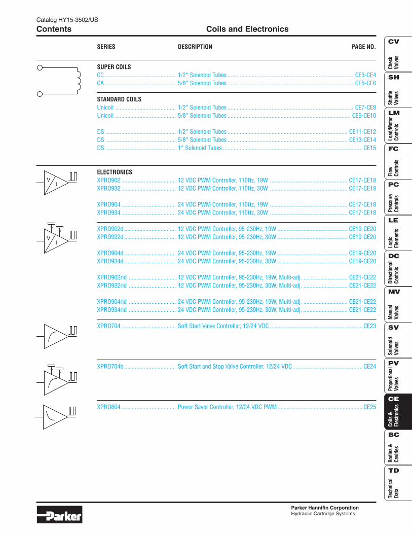
Diodes Internally molded diodes are available. Polarity is molded into coil for ease of installation.
Ribbed SurfaceExternal ridgesprovide a larger
coil surface area, whichallows for better heat dissipation.
Rugged Thermoplastic EncapsulationCoil is encased in a thermoplastic polyester resin.This allows for higher temperature exposure andless flexural creep. Also, this resin is resistant to
moisture, caustic solutions,and fungus providing
protection forcoil windings.
Low CarbonSteel FrameZinc plated lowcarbon steel framesurrounds coil, increasingflux density. Low carbon steel provides bettermagnetic properties and greater permeability.
Variety of Terminations Coils are offered in a wide variety of terminations, including integrally molded connectors and voltages to meet your system requirements.
DC Windings All coils are DC wound. An internal full wave rectifier is added for AC current, eliminating inrush current, and allowing for voltage interchangeability.
Class N Magnetic WireInternal wires have a class Nrating, providing longerlife at typicaltemperatures.
Catalog HY15-3502/US
Coils and Electronics
CE2 Parker Hannifin CorporationHydraulic Cartridge Systems
Technical Tips
Chec
kVa
lves
Shut
tleVa
lves
Load
/Mot
orCo
ntro
lsFl
owCo
ntro
lsPr
essu
reCo
ntro
lsLo
gic
Elem
ents
Dire
ctio
nal
Cont
rols
Man
ual
Valv
esPr
opor
tiona
lVa
lves
Coils
&El
ectro
nics
Tech
nica
lDa
ta
SH
CV
LM
FC
PC
LE
DC
MV
SV
PV
CE
BC
TD
Bodi
es &
Cavi
ties
Sole
noid
Valv
es
Cable Gland
Conduit Conduit
Voltages: Parker has a wide selection of coils avail-able to meet your needs. Most coil terminations areavailable with our standard voltages of 12V and 24V inDC, and 120V and 240V in AC. Voltages 6V, 10V, 18V,36V, 48V DC and 440V AC are also available for manytermination types at a slight premium. Contact yourParker representative should your application call forvoltages other than our standard offering.
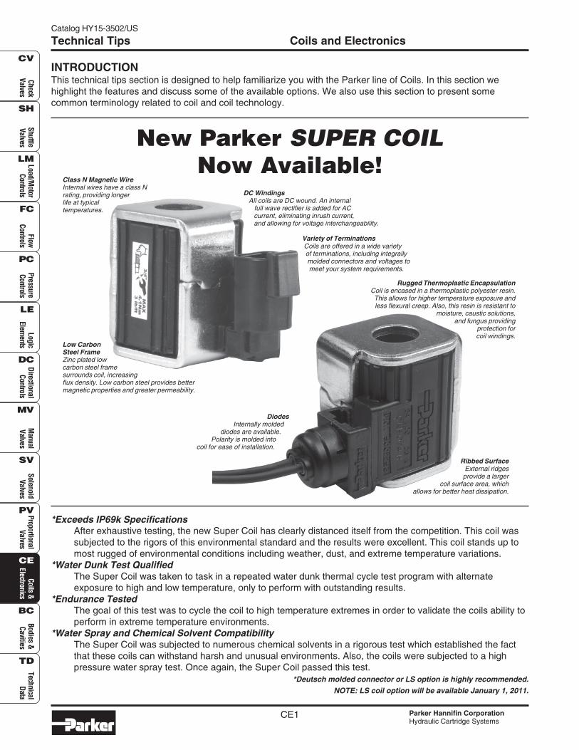
Diodes: The Parker Coils can be ordered with a diodemolded internally. Parker Unicoils use a IN5062 diode.The Super Coils use a IN5627 diode. Diodes aresometimes used to protect sensitive, downstreamelectrical components from potential surges from thecoil. By internally molding the diode into the coil, youcan reduce the assembly timeand cost associated withexternally wiring a diode.One should be carefulnot to switch the polarity(“+” and “-” terminals), when wiring a coil with aninternal diode. If these terminals are switched, the firsttime voltage is applied to the coil; the short circuit willdestroy the diode and render the coil use-less. Parkercoils with diodes have “+” and “-” molded near thetermination outlet to help identify polarity.
DIN Connectors: Parker does offer connectors for usewith the DIN style coils. As shown below, the DINconnectors are available in both rectified and non-rectified forms. The cable gland versions can beordered for type PG9 or PG11.
Continuous Duty: Parker’s standard line of coils arerated for continuous duty operation. This means thecoil can be left on continuously without fear of themagnet wire insulation breakdown, when used instandard climate conditions. The Unicoils and SuperCoils are made of a high quality Class N magnet wire.This Class N rating signifies the internal wires arerated to 200°C (392°F).
Continuous duty does not mean the coil will have thesame amount of power after hours of operation as ithad at initial actuation. Coils do heat up during use.This internal heat rise increases the resistance of thecoil and thus, decreases the current (V = IR). Theperformance curves presented on the solenoid valvepages are based on a coil at room temperature and85% of voltage. Thus, when using a valve in continu-ous duty applications, you may need to derate theperformance. In short, the continuous duty ratingsignifies that while the coil will get hot during use andresistance will increase, it will not generate enoughheat to damage the coil.
Terminations: Parker offers a wide variety of coilterminations for all coils to meet the demands of yourapplication. Over the years, the dual lead wire and dualspade offerings have been popular due to their ease ofinstallation and availability. In the past few years, thedemand for more secure termination connections hasincreased. In addition, the integral connectors reducecost and improve integrity by reducing the number ofconnections. As such, the Amp Junior, Weatherpack,Metri-Pack, and Deutsch have increased in popularity.We offer these connectors on a lead wire coil, as wellas an internally molded version of the DIN, AmpJunior, and Metri-Pack coils. If you do not find yourdesired coil termination in our catalog, contact yourfactory sales representative. We have added a SealedLeadwire option to meet IP69K requirements yet stillallow for other lead wire options.
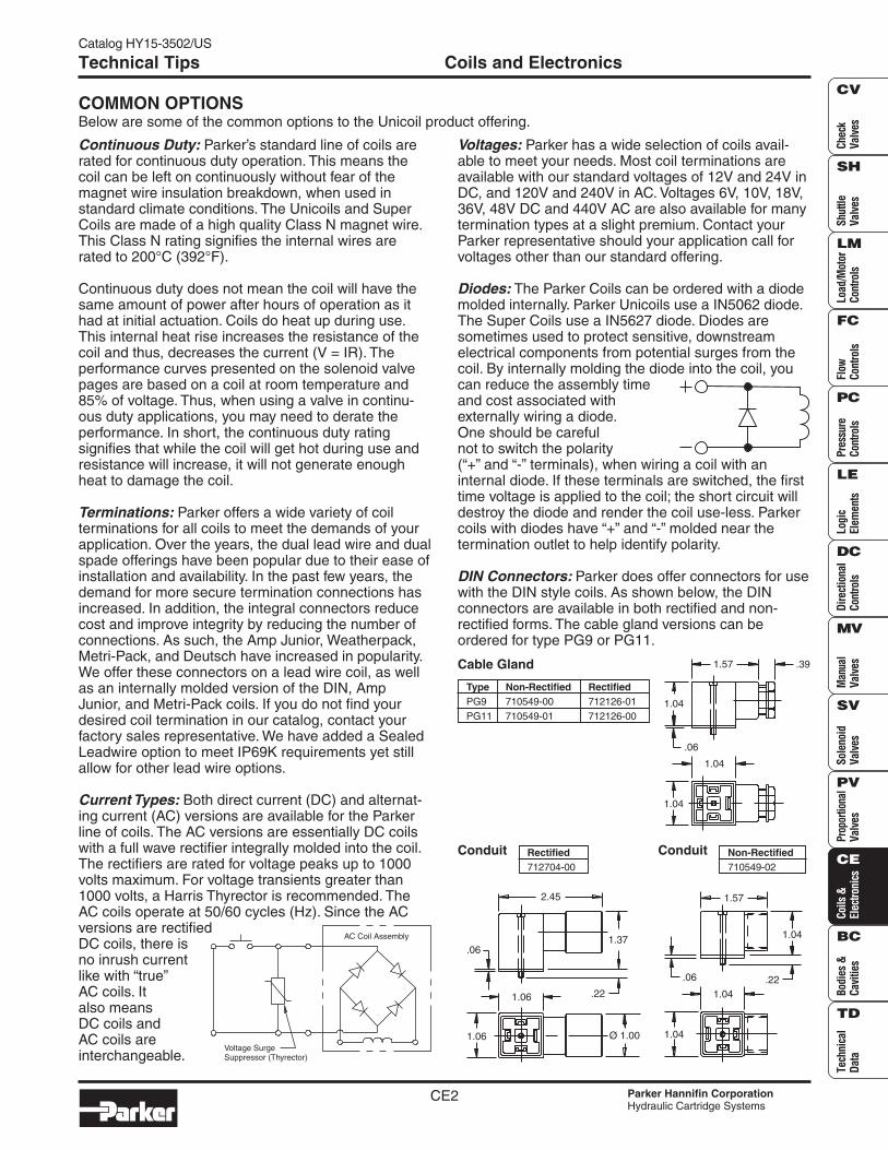
Current Types: Both direct current (DC) and alternat-ing current (AC) versions are available for the Parkerline of coils. The AC versions are essentially DC coilswith a full wave rectifier integrally molded into the coil.The rectifiers are rated for voltage peaks up to 1000volts maximum. For voltage transients greater than1000 volts, a Harris Thyrector is recommended. TheAC coils operate at 50/60 cycles (Hz). Since the ACversions are rectifiedDC coils, there isno inrush currentlike with “true”AC coils. Italso meansDC coils andAC coils areinterchangeable.
Rectified712704-00
Non-Rectified710549-02
Type Non-Rectified RectifiedPG9 710549-00 712126-01PG11 710549-01 712126-00
COMMON OPTIONSBelow are some of the common options to the Unicoil product offering.
1.04
1.04
1.04
.391.57
.06
.22
Ø 1.001.06
1.06
.061.37
2.45
1.04
.221.04
.06
1.57
1.04
AC Coil Assembly
Voltage SurgeSuppressor (Thyrector)
CE3
Catalog HY15-3502/US Super CoilSeries 1/2″″″″″ I.D.
Parker Hannifin CorporationHydraulic Cartridge Systems
CheckValves
ShuttleValves
Load/Motor
ControlsFlow
ControlsPressureControls
LogicElem
entsDirectional
ControlsM
anualValves
SolenoidValves
ProportionalValves
Coils &Electronics
Bodies &Cavities
TechnicalData
SH
CV
LM
FC
PC
LE
DC
MV
SV
PV
CE
BC
TD
Technical Information
Specifications
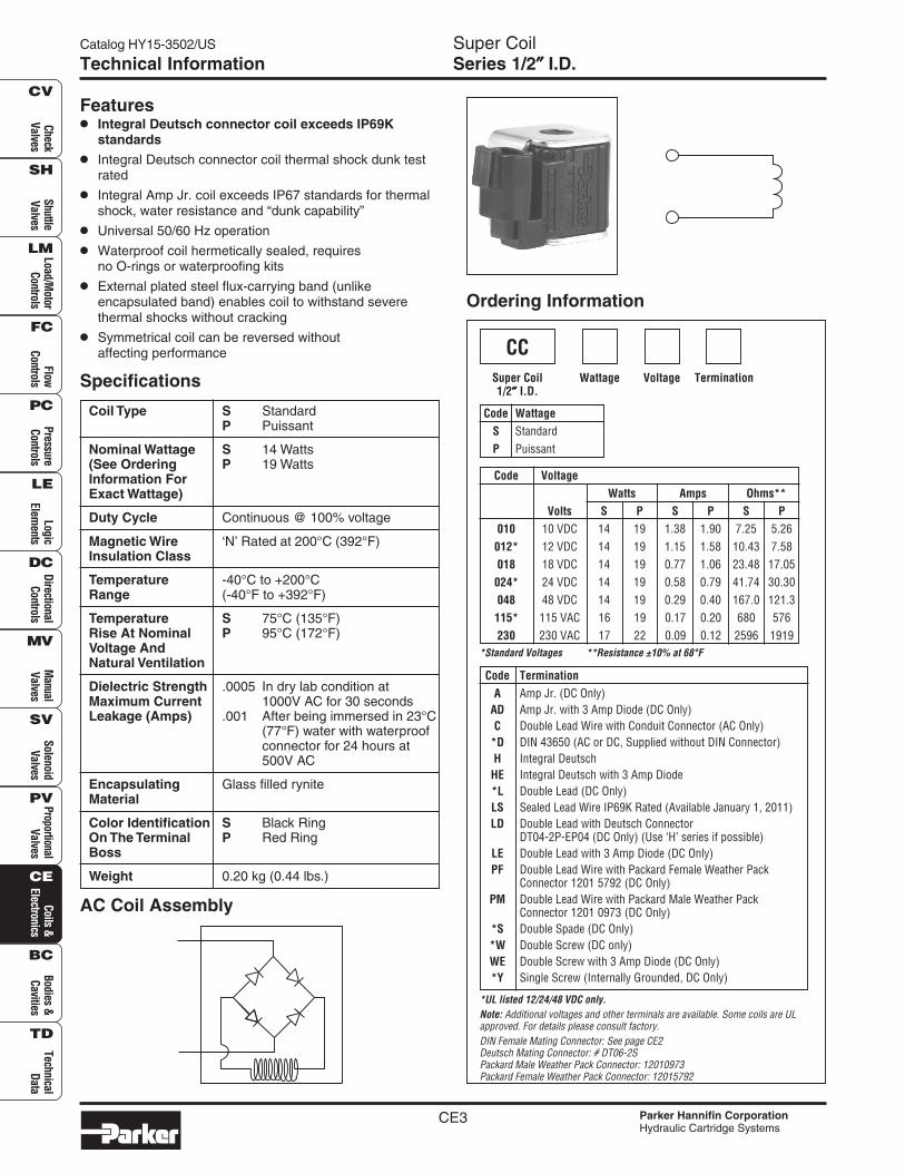
Features• Integral Deutsch connector coil exceeds IP69K
standards
• Integral Deutsch connector coil thermal shock dunk testrated
• Integral Amp Jr. coil exceeds IP67 standards for thermalshock, water resistance and “dunk capability”
• Universal 50/60 Hz operation
• Waterproof coil hermetically sealed, requiresno O-rings or waterproofing kits
• External plated steel flux-carrying band (unlikeencapsulated band) enables coil to withstand severethermal shocks without cracking
• Symmetrical coil can be reversed withoutaffecting performance
Coil Type S StandardP Puissant
Nominal Wattage S 14 Watts(See Ordering P 19 WattsInformation ForExact Wattage)
Duty Cycle Continuous @ 100% voltage
Magnetic Wire ‘N’ Rated at 200°C (392°F)Insulation Class
Temperature -40°C to +200°CRange (-40°F to +392°F)
Temperature S 75°C (135°F)Rise At Nominal P 95°C (172°F)Voltage AndNatural Ventilation
Dielectric Strength .0005 In dry lab condition atMaximum Current 1000V AC for 30 secondsLeakage (Amps) .001 After being immersed in 23°C
(77°F) water with waterproofconnector for 24 hours at500V AC
Encapsulating Glass filled ryniteMaterial
Color Identification S Black RingOn The Terminal P Red RingBoss
Weight 0.20 kg (0.44 lbs.)
AC Coil Assembly
Ordering Information
TerminationVoltage
CCSuper Coil1/2″″″″″ I.D.
Wattage
Code VoltageWatts Amps Ohms**
Volts S P S P S P010 10 VDC 14 19 1.38 1.90 7.25 5.26012* 12 VDC 14 19 1.15 1.58 10.43 7.58018 18 VDC 14 19 0.77 1.06 23.48 17.05024* 24 VDC 14 19 0.58 0.79 41.74 30.30048 48 VDC 14 19 0.29 0.40 167.0 121.3115* 115 VAC 16 19 0.17 0.20 680 576230 230 VAC 17 22 0.09 0.12 2596 1919
Code TerminationA Amp Jr. (DC Only)
AD Amp Jr. with 3 Amp Diode (DC Only)C Double Lead Wire with Conduit Connector (AC Only)
*D DIN 43650 (AC or DC, Supplied without DIN Connector)H Integral Deutsch
HE Integral Deutsch with 3 Amp Diode*L Double Lead (DC Only)LS Sealed Lead Wire IP69K Rated (Available January 1, 2011)LD Double Lead with Deutsch Connector
DT04-2P-EP04 (DC Only) (Use ‘H’ series if possible)LE Double Lead with 3 Amp Diode (DC Only)PF Double Lead Wire with Packard Female Weather Pack
Connector 1201 5792 (DC Only)PM Double Lead Wire with Packard Male Weather Pack
Connector 1201 0973 (DC Only)*S Double Spade (DC Only)*W Double Screw (DC only)WE Double Screw with 3 Amp Diode (DC Only)*Y Single Screw (Internally Grounded, DC Only)
Code WattageS StandardP Puissant
*Standard Voltages **Resistance ±10% at 68°F
*UL listed 12/24/48 VDC only.Note: Additional voltages and other terminals are available. Some coils are ULapproved. For details please consult factory.DIN Female Mating Connector: See page CE2Deutsch Mating Connector: # DT06-2SPackard Male Weather Pack Connector: 12010973Packard Female Weather Pack Connector: 12015792
CE4
Super CoilSeries 1/2″″″″″ I.D.
Catalog HY15-3502/US
Parker Hannifin CorporationHydraulic Cartridge Systems
Chec
kVa
lves
Shut
tleVa
lves
Load
/Mot
orCo
ntro
lsFl
owCo
ntro
lsPr
essu
reCo
ntro
lsLo
gic
Elem
ents
Dire
ctio
nal
Cont
rols
Man
ual
Valv
esPr
opor
tiona
lVa
lves
Coils
&El
ectro
nics
Tech
nica
lDa
ta
SH
CV
LM
FC
PC
LE
DC
MV
SV
PV
CE
BC
TD
Bodi
es &
Cavi
ties
Sole
noid
Valv
es
Technical Information
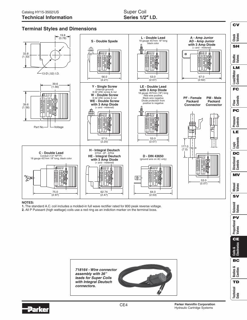
Terminal Styles and Dimensions
NOTES:1. The standard A.C. coil includes a molded-in full wave rectifier rated for 800 peak reverse voltage.2. All P Puissant (high wattage) coils use a red ring as an indiction marker on the terminal boss.
S - Double Spade
XX
VD
C X
XW
CC
X X
XX
H
MA
DE
INU
.S.A
.PAT.X
XX
XX
XX
56.0(2.21)
L - Double Lead18 gauge 457mm long
black color18"
XX
VD
C X
XW
CC
X X
XX
H
MA
DE
INU
.S.A
.PAT.X
XX
XX
XX
53.0(2.07)
LE - Double Leadwith 3 Amp Diode
18 gauge 457mm (18") longRed wire positive,
Black wire negativeDiode protection frompositive to negative
XX
VD
C X
XW
CC
X X
XX
H
MA
DE
INU
.S.A
.PAT.X
XX
XX
XX
53.0(2.07)
XX
VD
C X
XW
CC
X X
XX
H
MA
DE
INU
.S.A
.PAT.X
XX
XX
XX
57.0(2.25)
Y - Single Screw(Internal ground)
8-32 UNC screw & nutW - Double Screw
WE - Double Screwwith 3 Amp Diode
8-32 UNC screw & nut
(+ and - metered)
XX
VD
C X
XW
CC
X X
XX
H
MA
DE
INU
.S.A
.PAT.X
XX
XX
XX
67.0(2.62)
A - Amp JuniorAD - Amp Juniorwith 3 Amp Diode
(+ and - metered)
XX
VD
C X
XW
CC
X X
XX
H
MA
DE
INU
.S.A
.PAT.X
XX
XX
XX
64.0(2.53)
D - DIN 43650(ground wire on AC only)
C - Double LeadConduit (1/2" NPTF)
18 gauge 457mm long, black color18"
75.0(2.97)
XX
VD
C X
XW
CC
X X
XX
H
MA
DE
INU
.S.A
.PAT.X
XX
XX
XX
H - Integral DeutschDT04 - 2P - EP04
HE - Integral Deutschwith 3 Amp Diode
(+ and - metered)
62.74(2.47)
XX
VD
C X
XW
CC
X X
XX
H
MA
DE
INU
.S.A
.PAT.5002253
PF - FemalePackard
Connector
PM - MalePackard
Connector
XX
VD
C X
XW
CC
X X
XX
H
MA
DE
INU
.S.A
.PAT.X
XX
XX
XX
177.0(7.0)
53.0(2.07)
39.6(1.56)
Part No. Voltage
XX
VD
C X
XW
CC
X X
XX
H
MA
DE
INU
.S.A
.PAT.X
XX
XX
XX
39.6(1.56)
13 Ø (.52) I.D.
33.8(1.33)
19.8(0.78)
718164 - Wire connectorassembly with 36”leads for Super Coilswith Integral Deutschconnectors.
CE5
Catalog HY15-3502/US Super CoilSeries 5/8″″″″″ I.D.
Parker Hannifin CorporationHydraulic Cartridge Systems
CheckValves
ShuttleValves
Load/Motor
ControlsFlow
ControlsPressureControls
LogicElem
entsDirectional
ControlsM
anualValves
SolenoidValves
ProportionalValves
Coils &Electronics
Bodies &Cavities
TechnicalData
SH
CV
LM
FC
PC
LE
DC
MV
SV
PV
CE
BC
TD
Technical Information
Specifications
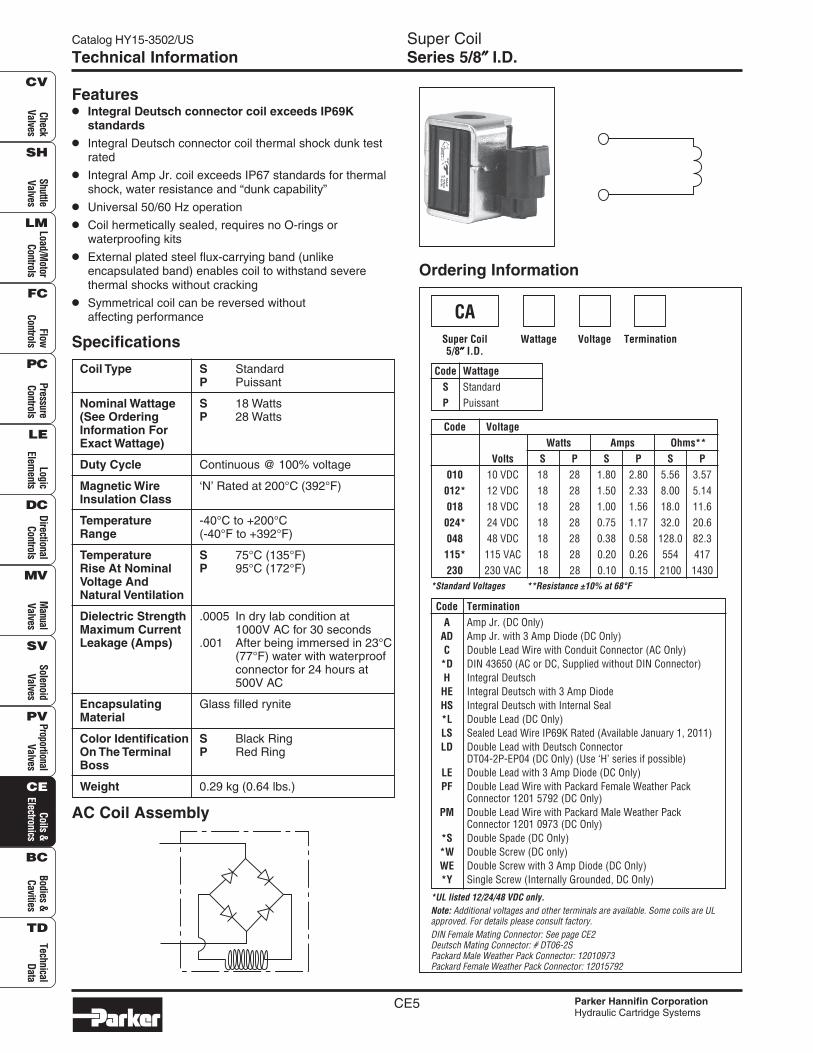
Features• Integral Deutsch connector coil exceeds IP69K
standards
• Integral Deutsch connector coil thermal shock dunk testrated
• Integral Amp Jr. coil exceeds IP67 standards for thermalshock, water resistance and “dunk capability”
• Universal 50/60 Hz operation
• Coil hermetically sealed, requires no O-rings orwaterproofing kits
• External plated steel flux-carrying band (unlikeencapsulated band) enables coil to withstand severethermal shocks without cracking
• Symmetrical coil can be reversed withoutaffecting performance
Coil Type S StandardP Puissant
Nominal Wattage S 18 Watts(See Ordering P 28 WattsInformation ForExact Wattage)
Duty Cycle Continuous @ 100% voltage
Magnetic Wire ‘N’ Rated at 200°C (392°F)Insulation Class
Temperature -40°C to +200°CRange (-40°F to +392°F)
Temperature S 75°C (135°F)Rise At Nominal P 95°C (172°F)Voltage AndNatural Ventilation
Dielectric Strength .0005 In dry lab condition atMaximum Current 1000V AC for 30 secondsLeakage (Amps) .001 After being immersed in 23°C
(77°F) water with waterproofconnector for 24 hours at500V AC
Encapsulating Glass filled ryniteMaterial
Color Identification S Black RingOn The Terminal P Red RingBoss
Weight 0.29 kg (0.64 lbs.)
AC Coil Assembly
Ordering Information
TerminationVoltage
CASuper Coil5/8″″″″″ I.D.
Wattage
Code VoltageWatts Amps Ohms**
Volts S P S P S P010 10 VDC 18 28 1.80 2.80 5.56 3.57012* 12 VDC 18 28 1.50 2.33 8.00 5.14018 18 VDC 18 28 1.00 1.56 18.0 11.6024* 24 VDC 18 28 0.75 1.17 32.0 20.6048 48 VDC 18 28 0.38 0.58 128.0 82.3115* 115 VAC 18 28 0.20 0.26 554 417230 230 VAC 18 28 0.10 0.15 2100 1430
Code TerminationA Amp Jr. (DC Only)
AD Amp Jr. with 3 Amp Diode (DC Only)C Double Lead Wire with Conduit Connector (AC Only)
*D DIN 43650 (AC or DC, Supplied without DIN Connector)H Integral Deutsch
HE Integral Deutsch with 3 Amp DiodeHS Integral Deutsch with Internal Seal*L Double Lead (DC Only)LS Sealed Lead Wire IP69K Rated (Available January 1, 2011)LD Double Lead with Deutsch Connector
DT04-2P-EP04 (DC Only) (Use ‘H’ series if possible)LE Double Lead with 3 Amp Diode (DC Only)PF Double Lead Wire with Packard Female Weather Pack
Connector 1201 5792 (DC Only)PM Double Lead Wire with Packard Male Weather Pack
Connector 1201 0973 (DC Only)*S Double Spade (DC Only)*W Double Screw (DC only)WE Double Screw with 3 Amp Diode (DC Only)*Y Single Screw (Internally Grounded, DC Only)
Code WattageS StandardP Puissant
*Standard Voltages **Resistance ±10% at 68°F
*UL listed 12/24/48 VDC only.Note: Additional voltages and other terminals are available. Some coils are ULapproved. For details please consult factory.DIN Female Mating Connector: See page CE2Deutsch Mating Connector: # DT06-2SPackard Male Weather Pack Connector: 12010973Packard Female Weather Pack Connector: 12015792
CE6
Super CoilSeries 5/8″″″″″ I.D.
Catalog HY15-3502/US
Parker Hannifin CorporationHydraulic Cartridge Systems
Chec
kVa
lves
Shut
tleVa
lves
Load
/Mot
orCo
ntro
lsFl
owCo
ntro
lsPr
essu
reCo
ntro
lsLo
gic
Elem
ents
Dire
ctio
nal
Cont
rols
Man
ual
Valv
esPr
opor
tiona
lVa
lves
Coils
&El
ectro
nics
Tech
nica
lDa
ta
SH
CV
LM
FC
PC
LE
DC
MV
SV
PV
CE
BC
TD
Bodi
es &
Cavi
ties
Sole
noid
Valv
es
Technical Information
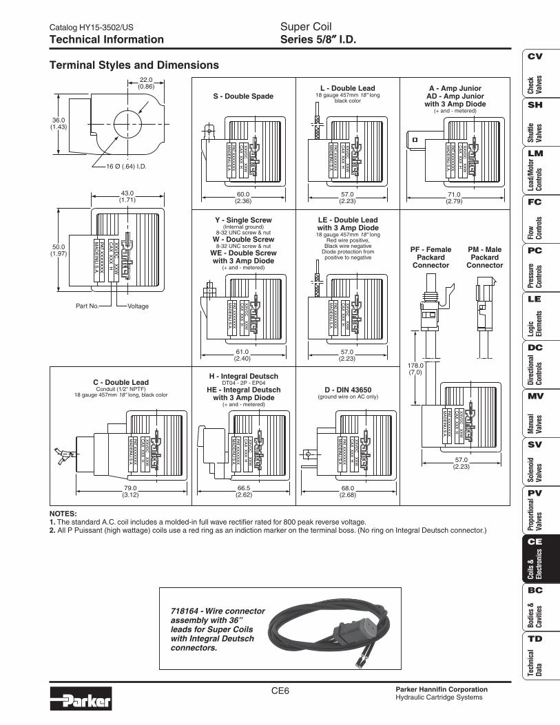
Terminal Styles and Dimensions
NOTES:1. The standard A.C. coil includes a molded-in full wave rectifier rated for 800 peak reverse voltage.2. All P Puissant (high wattage) coils use a red ring as an indiction marker on the terminal boss. (No ring on Integral Deutsch connector.)
S - Double Spade
XX
VD
C X
XW
CA
X X
XX
H
PAT.XX
XX
XX
XM
AD
EIN
U.S
.A.
60.0(2.36)
L - Double Lead18 gauge 457mm long
black color18"
XX
VD
C X
XW
CA
X X
XX
H
PAT.XX
XX
XX
XM
AD
EIN
U.S
.A.
57.0(2.23)
XX
VD
C X
XW
CA
X X
XX
H
PAT.XX
XX
XX
XM
AD
EIN
U.S
.A.
79.0(3.12)
C - Double LeadConduit (1/2" NPTF)
18 gauge 457mm long, black color18"
XX
VD
C X
XW
CA
X X
XX
H
PAT.XX
XX
XX
XM
AD
EIN
U.S
.A.
57.0(2.23)
PF - FemalePackard
Connector
PM - MalePackard
Connector
178.0(7.0)
Y - Single Screw(Internal ground)
8-32 UNC screw & nutW - Double Screw
WE - Double Screwwith 3 Amp Diode
8-32 UNC screw & nut
(+ and - metered)
61.0(2.40)
XX
VD
C X
XW
CA
X X
XX
H
PAT.XX
XX
XX
XM
AD
EIN
U.S
.A.
A - Amp JuniorAD - Amp Juniorwith 3 Amp Diode
(+ and - metered)
71.0(2.79)
XX
VD
C X
XW
CA
X X
XX
H
PAT.XX
XX
XX
XM
AD
EIN
U.S
.A.
LE - Double Leadwith 3 Amp Diode18 gauge 457mm long
Red wire positive,Black wire negative
Diode protection frompositive to negative
18"
57.0(2.23)
XX
VD
C X
XW
CA
X X
XX
H
PAT.XX
XX
XX
XM
AD
EIN
U.S
.A.
D - DIN 43650(ground wire on AC only)
68.0(2.68)
XX
VD
C X
XW
CA
X X
XX
H
PAT.XX
XX
XX
XM
AD
EIN
U.S
.A.
VoltagePart No.
50.0(1.97)
43.0(1.71)
XX
VD
C X
XW
CA
X X
XX
H
PAT.XX
XX
XX
XM
AD
EIN
U.S
.A.
22.0(0.86)
36.0(1.43)
16 Ø (.64) I.D.
H - Integral DeutschDT04 - 2P - EP04
HE - Integral Deutschwith 3 Amp Diode
(+ and - metered)
XX
VD
C X
XW
CA
X X
XX
H
PAT.XX
XX
XX
XM
AD
EIN
U.S
.A.
66.5(2.62)
718164 - Wire connectorassembly with 36”leads for Super Coilswith Integral Deutschconnectors.
CE7
Catalog HY15-3502/US UnicoilSeries 1/2″″″″″ I.D.
Parker Hannifin CorporationHydraulic Cartridge Systems
CheckValves
ShuttleValves
Load/Motor
ControlsFlow
ControlsPressureControls
LogicElem
entsDirectional
ControlsM
anualValves
SolenoidValves
ProportionalValves
Coils &Electronics
Bodies &Cavities
TechnicalData
SH
CV
LM
FC
PC
LE
DC
MV
SV
PV
CE
BC
TD
Specifications
Ordering Information
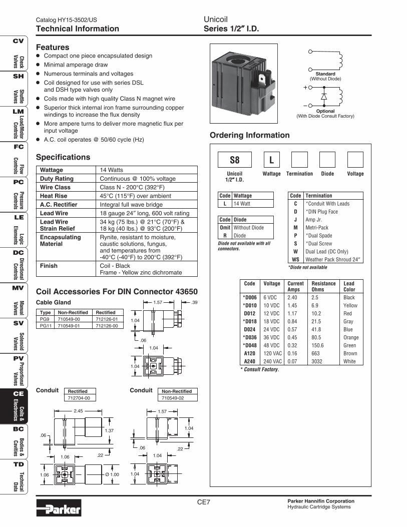
Wattage 14 Watts
Duty Rating Continuous @ 100% voltageWire Class Class N - 200°C (392°F)Heat Rise 45°C (115°F) over ambient
A.C. Rectifier Integral full wave bridgeLead Wire 18 gauge 24″ long, 600 volt ratingLead Wire 34 kg (75 lbs.) @ 21°C (70°F) &Strain Relief 18 kg (40 lbs.) @ 93°C (200°F)Encapsulating Rynite, resistant to moisture,Material caustic solutions, fungus,
and temperatures from-40°C (-40°F) to 200°C (392°F)
Finish Coil - BlackFrame - Yellow zinc dichromate
Features• Compact one piece encapsulated design
• Minimal amperage draw
• Numerous terminals and voltages
• Coil designed for use with series DSLand DSH type valves only
• Coils made with high quality Class N magnet wire
• Superior thick internal iron frame surrounding copperwindings to increase the flux density
• More ampere turns to deliver more magnetic flux perinput voltage
• A.C. coil operates @ 50/60 cycle (Hz)
VoltageDiodeTermination
S8Unicoil
1/2″″″″″ I.D.Wattage
Code Voltage Current Resistance LeadAmps Ohms Color
*D006 6 VDC 2.40 2.5 Black*D010 10 VDC 1.45 6.9 YellowD012 12 VDC 1.17 10.2 Red*D018 18 VDC 0.84 21.5 GrayD024 24 VDC 0.57 41.8 Blue*D036 36 VDC 0.45 80.5 Orange*D048 48 VDC 0.32 150.6 GreenA120 120 VAC 0.16 663 BrownA240 240 VAC 0.07 3032 White
Code TerminationC *Conduit With LeadsD *DIN Plug FaceJ Amp Jr.M Metri-PackP *Dual SpadeS *Dual ScrewW Dual Lead (DC Only)
WS Weather Pack Shroud 24″
Code WattageL 14 Watt
Code DiodeOmit Without Diode
R Diode
*Diode not available
L
Diode not available with allconnectors.
Coil Accessories For DIN Connector 43650Cable Gland
Type Non-Rectified RectifiedPG9 710549-00 712126-01PG11 710549-01 712126-00
Conduit Rectified712704-00
Conduit Non-Rectified710549-02
Optional(With Diode Consult Factory)
Standard(Without Diode)
Technical Information
1.04
1.04
1.04
.391.57
.06
.22
Ø 1.001.06
1.06
.061.37
2.45
1.04
.221.04
.06
1.57
1.04
* Consult Factory.
CE8
UnicoilSeries 1/2″″″″″ I.D.
Catalog HY15-3502/US
Parker Hannifin CorporationHydraulic Cartridge Systems
Chec
kVa
lves
Shut
tleVa
lves
Load
/Mot
orCo
ntro
lsFl
owCo
ntro
lsPr
essu
reCo
ntro
lsLo
gic
Elem
ents
Dire
ctio
nal
Cont
rols
Man
ual
Valv
esPr
opor
tiona
lVa
lves
Coils
&El
ectro
nics
Tech
nica
lDa
ta
SH
CV
LM
FC
PC
LE
DC
MV
SV
PV
CE
BC
TD
Bodi
es &
Cavi
ties
Sole
noid
Valv
es
Technical Information
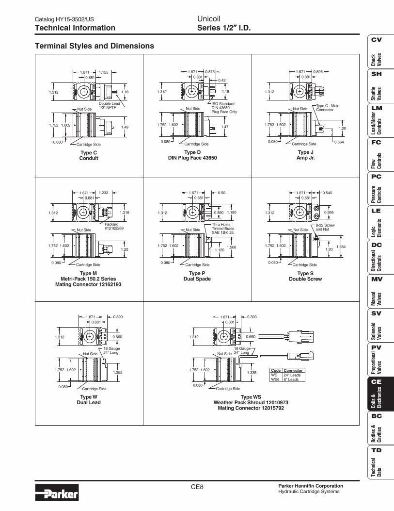
Terminal Styles and Dimensions
Double Lead1/2" NPTF
1.312
1.6710.881
1.155
1.18
Nut Side
1.49
Cartridge Side0.080
1.752 1.602
Type CConduit
Nut Side
Cartridge Side0.080
1.752 1.602
Type DDIN Plug Face 43650
1.47
ISO StandardDIN 43650Plug Face Only
1.181.312
1.6710.881
0.875
0.42
Nut Side
Cartridge Side0.080
1.752 1.602
Type JAmp Jr.
Type C - MaleConnector
1.20
0.564
1.312
1.671 0.8960.881
1.752 1.602
Type SDouble Screw
Cartridge Side
Nut Side8-32 Screwand Nut
1.201.584
0.080
1.312 0.995
0.5451.6710.881
1.752 1.602
Type MMetri-Pack 150.2 Series
Mating Connector 12162193
0.080 Cartridge Side
Nut Side
1.312
1.6710.881
1.233
1.316
1.20
Packard#12162269
1.752 1.602
Type PDual Spade
0.080 Cartridge Side
1.1201.506
Nut SideThru HolesTinned BrassSAE 1B-0.25
0.860 1.180
0.50
1.312
1.6710.881
1.752 1.602
0.080
Type WDual Lead
Cartridge Side
Nut Side18 Gauge24" Long
1.355
1.312
1.6710.881
0.390
0.660
1.752 1.602
Type WSWeather Pack Shroud 12010973
Mating Connector 12015792
CodeWSWS6
Connector24" Leads6" Leads
Cartridge Side
1.335
0.080
Nut Side18 Gauge24" Long
0.660
0.3901.6710.881
1.312
CE9
Catalog HY15-3502/US UnicoilSeries 5/8″″″″″ I.D.
Parker Hannifin CorporationHydraulic Cartridge Systems
CheckValves
ShuttleValves
Load/Motor
ControlsFlow
ControlsPressureControls
LogicElem
entsDirectional
ControlsM
anualValves
SolenoidValves
ProportionalValves
Coils &Electronics
Bodies &Cavities
TechnicalData
SH
CV
LM
FC
PC
LE
DC
MV
SV
PV
CE
BC
TD
Specifications
Ordering Information
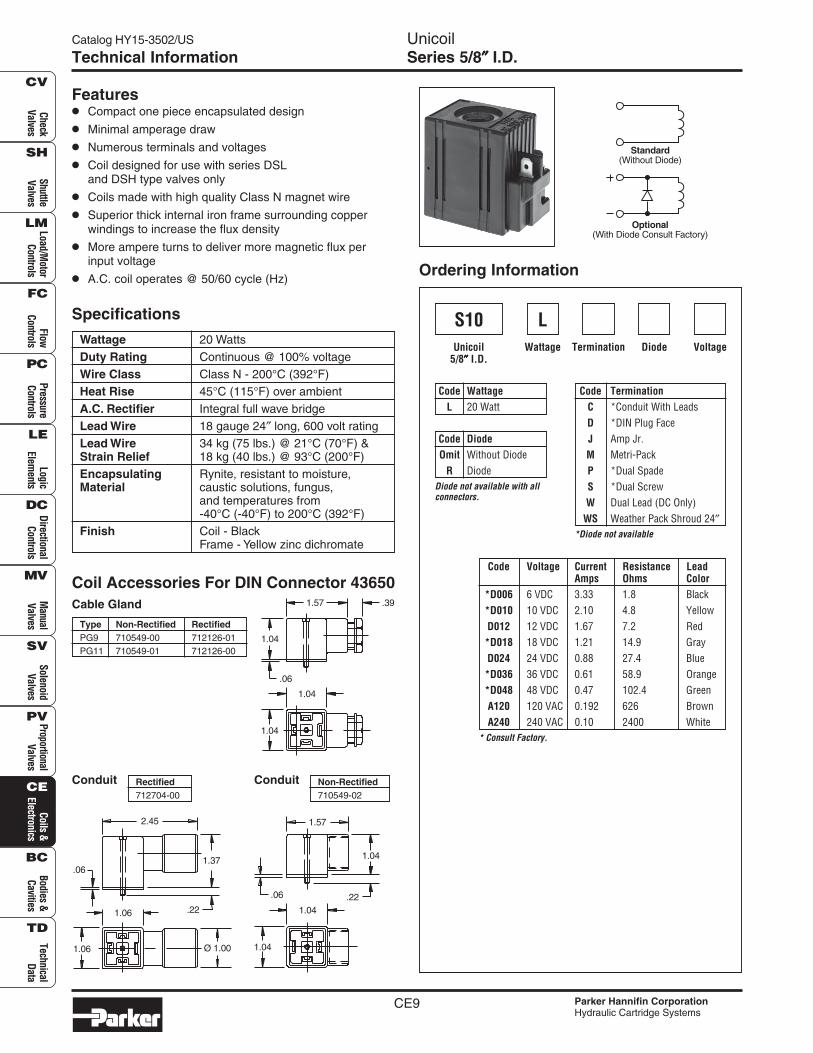
Wattage 20 Watts
Duty Rating Continuous @ 100% voltageWire Class Class N - 200°C (392°F)Heat Rise 45°C (115°F) over ambient
A.C. Rectifier Integral full wave bridgeLead Wire 18 gauge 24″ long, 600 volt ratingLead Wire 34 kg (75 lbs.) @ 21°C (70°F) &Strain Relief 18 kg (40 lbs.) @ 93°C (200°F)Encapsulating Rynite, resistant to moisture,Material caustic solutions, fungus,
and temperatures from-40°C (-40°F) to 200°C (392°F)
Finish Coil - BlackFrame - Yellow zinc dichromate
Features• Compact one piece encapsulated design
• Minimal amperage draw
• Numerous terminals and voltages
• Coil designed for use with series DSLand DSH type valves only
• Coils made with high quality Class N magnet wire
• Superior thick internal iron frame surrounding copperwindings to increase the flux density
• More ampere turns to deliver more magnetic flux perinput voltage
• A.C. coil operates @ 50/60 cycle (Hz)
VoltageDiodeTermination
S10Unicoil
5/8″″″″″ I.D.Wattage
Code Voltage Current Resistance LeadAmps Ohms Color
*D006 6 VDC 3.33 1.8 Black*D010 10 VDC 2.10 4.8 YellowD012 12 VDC 1.67 7.2 Red*D018 18 VDC 1.21 14.9 GrayD024 24 VDC 0.88 27.4 Blue*D036 36 VDC 0.61 58.9 Orange*D048 48 VDC 0.47 102.4 GreenA120 120 VAC 0.192 626 BrownA240 240 VAC 0.10 2400 White
Code TerminationC *Conduit With LeadsD *DIN Plug FaceJ Amp Jr.M Metri-PackP *Dual SpadeS *Dual ScrewW Dual Lead (DC Only)
WS Weather Pack Shroud 24″
Code WattageL 20 Watt
Code DiodeOmit Without Diode
R Diode
*Diode not available
L
Diode not available with allconnectors.
Coil Accessories For DIN Connector 43650Cable Gland
Type Non-Rectified RectifiedPG9 710549-00 712126-01PG11 710549-01 712126-00
Conduit Rectified712704-00
Conduit Non-Rectified710549-02
Technical Information
Optional(With Diode Consult Factory)
Standard(Without Diode)
1.04
1.04
1.04
.391.57
.06
.22
Ø 1.001.06
1.06
.061.37
2.45
1.04
.221.04
.06
1.57
1.04
* Consult Factory.
CE10
UnicoilSeries 5/8″″″″″ I.D.
Catalog HY15-3502/US
Parker Hannifin CorporationHydraulic Cartridge Systems
Chec
kVa
lves
Shut
tleVa
lves
Load
/Mot
orCo
ntro
lsFl
owCo
ntro
lsPr
essu
reCo
ntro
lsLo
gic
Elem
ents
Dire
ctio
nal
Cont
rols
Man
ual
Valv
esPr
opor
tiona
lVa
lves
Coils
&El
ectro
nics
Tech
nica
lDa
ta
SH
CV
LM
FC
PC
LE
DC
MV
SV
PV
CE
BC
TD
Bodi
es &
Cavi
ties
Sole
noid
Valv
es
Technical Information
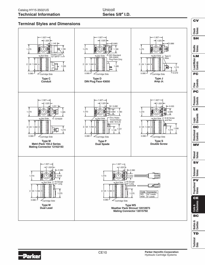
Terminal Styles and Dimensions
1.927
1.0250.886
Type CMale
Nut Side
1.470
2.124 1.964
0.080 Cartridge Side0.579
1.215
Type JAmp Jr.
2.124 1.964
1.470
1.927
1.0250.535
0.995
8-32 Screwand Nut
Nut Side
0.080 Cartridge Side
1.2151.599
Type SDouble Screw
2.124 1.964
0.080 Cartridge Side
1.215
Nut Side 1216229
1.927
1.0251.231
1.3851.470
Type MMetri-Pack 150.2 Series
Mating Connector 12162193
1.964
0.080 Cartridge Side
1.485
Nut Side ISO StandardDIN 43650Plug Face Only
1.927
1.025
0.865
1.1801.470
Type DDIN Plug Face 43650
2.124
2.124 1.964
0.080 Cartridge Side
1.370
Nut Side 18 Gauge24" Long
0.652
1.927
1.0250.380
1.470
Type WDual Lead
1.964
0.080 Cartridge Side
Type CConduit
1.505
Nut SideDouble Lead1/2" NPTF
1.180
1.927
1.0251.145
1.470
2.124
Type PDual Spade
2.124 1.964
0.080 Cartridge Side
1.1351.521
Nut Side Thru HolesTinned BrassSAE 18-0.25
0.860 1.180
0.490
1.927
1.025
1.470
CodeWSWS6
Connector24" Leads6" Leads
2.124 1.964
0.080 Cartridge Side
1.370
Nut Side 18 Gauge24" Long
0.652
1.927
1.0250.380
1.470
Type WSWeather Pack Shroud 12010973
Mating Connector 12015792
CE11
Catalog HY15-3502/US DS CoilSeries 1/2″″″″″ I.D.
Parker Hannifin CorporationHydraulic Cartridge Systems
CheckValves
ShuttleValves
Load/Motor
ControlsFlow
ControlsPressureControls
LogicElem
entsDirectional
ControlsM
anualValves
SolenoidValves
ProportionalValves
Coils &Electronics
Bodies &Cavities
TechnicalData
SH
CV
LM
FC
PC
LE
DC
MV
SV
PV
CE
BC
TD
Technical Information
Specifications
Features
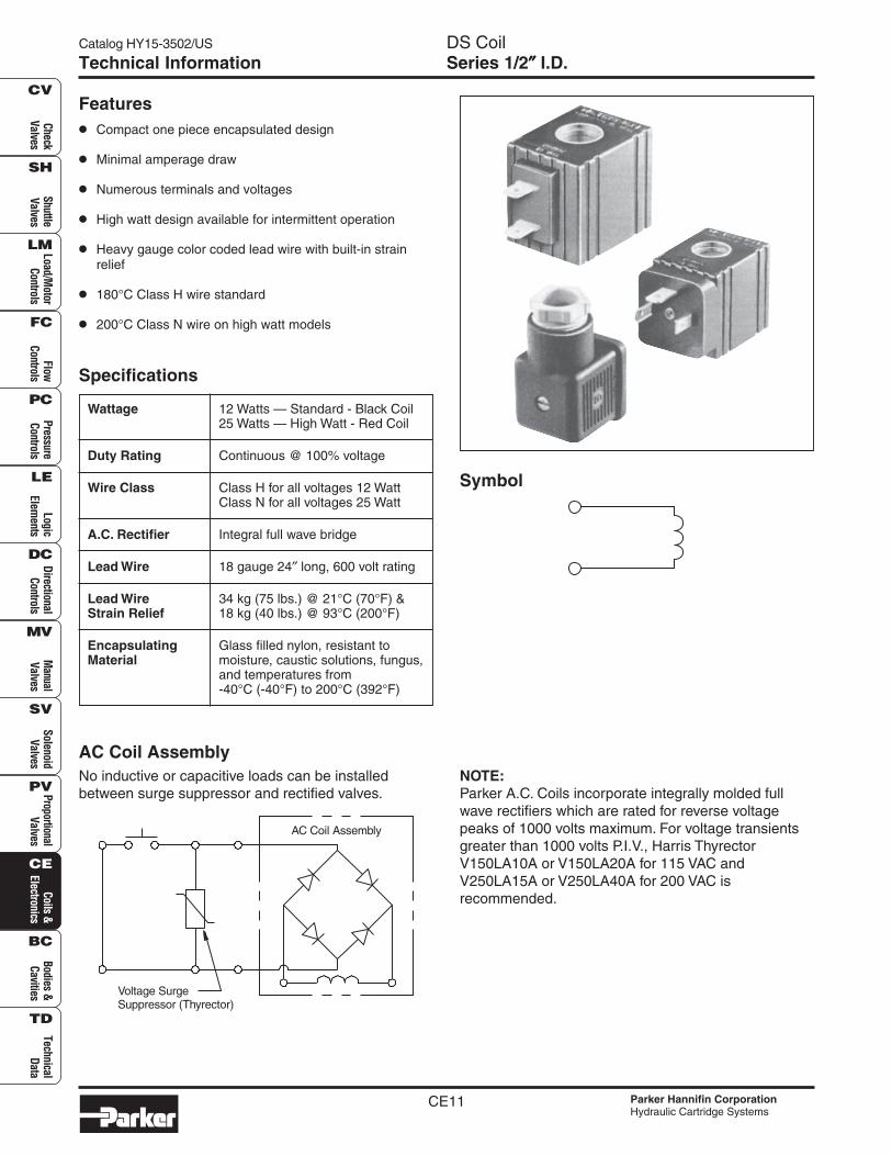
• Compact one piece encapsulated design
• Minimal amperage draw
• Numerous terminals and voltages
• High watt design available for intermittent operation
• Heavy gauge color coded lead wire with built-in strainrelief
• 180°C Class H wire standard
• 200°C Class N wire on high watt models
Wattage 12 Watts — Standard - Black Coil25 Watts — High Watt - Red Coil
Duty Rating Continuous @ 100% voltage
Wire Class Class H for all voltages 12 WattClass N for all voltages 25 Watt
A.C. Rectifier Integral full wave bridge
Lead Wire 18 gauge 24″ long, 600 volt rating
Lead Wire 34 kg (75 lbs.) @ 21°C (70°F) &Strain Relief 18 kg (40 lbs.) @ 93°C (200°F)
Encapsulating Glass filled nylon, resistant toMaterial moisture, caustic solutions, fungus,
and temperatures from-40°C (-40°F) to 200°C (392°F)
AC Coil AssemblyNo inductive or capacitive loads can be installedbetween surge suppressor and rectified valves.
NOTE:Parker A.C. Coils incorporate integrally molded fullwave rectifiers which are rated for reverse voltagepeaks of 1000 volts maximum. For voltage transientsgreater than 1000 volts P.I.V., Harris ThyrectorV150LA10A or V150LA20A for 115 VAC andV250LA15A or V250LA40A for 200 VAC isrecommended.
Symbol
AC Coil Assembly
Voltage SurgeSuppressor (Thyrector)
CE12
DS CoilSeries 1/2″″″″″ I.D.
Catalog HY15-3502/US
Parker Hannifin CorporationHydraulic Cartridge Systems
Chec
kVa
lves
Shut
tleVa
lves
Load
/Mot
orCo
ntro
lsFl
owCo
ntro
lsPr
essu
reCo
ntro
lsLo
gic
Elem
ents
Dire
ctio
nal
Cont
rols
Man
ual
Valv
esPr
opor
tiona
lVa
lves
Coils
&El
ectro
nics
Tech
nica
lDa
ta
SH
CV
LM
FC
PC
LE
DC
MV
SV
PV
CE
BC
TD
Bodi
es &
Cavi
ties
Sole
noid
Valv
es
Technical Information
Terminal Styles and Dimensions
Coil Part Numbers
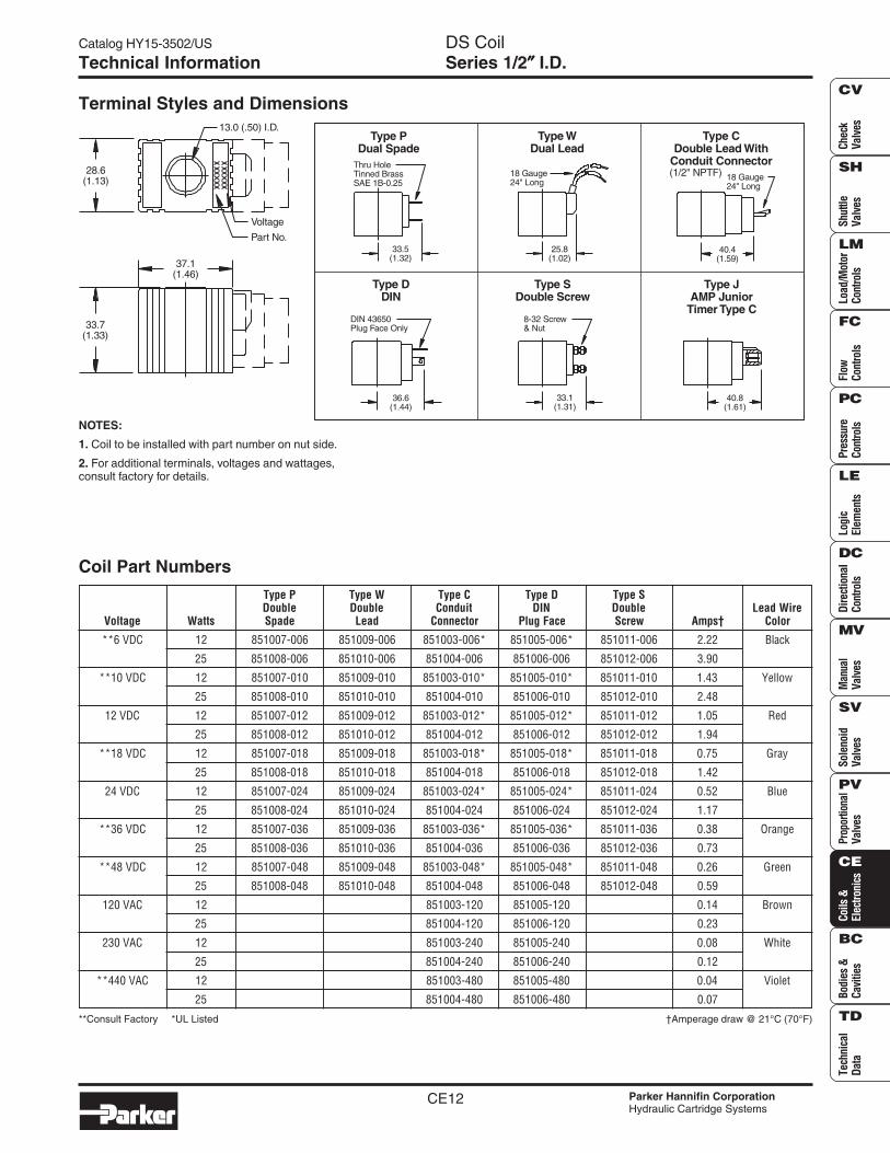
Type P Type W Type C Type D Type SDouble Double Conduit DIN Double Lead Wire
Voltage Watts Spade Lead Connector Plug Face Screw Amps† Color
**6 VDC 12 851007-006 851009-006 851003-006* 851005-006* 851011-006 2.22 Black
25 851008-006 851010-006 851004-006 851006-006 851012-006 3.90
**10 VDC 12 851007-010 851009-010 851003-010* 851005-010* 851011-010 1.43 Yellow
25 851008-010 851010-010 851004-010 851006-010 851012-010 2.48
12 VDC 12 851007-012 851009-012 851003-012* 851005-012* 851011-012 1.05 Red
25 851008-012 851010-012 851004-012 851006-012 851012-012 1.94
**18 VDC 12 851007-018 851009-018 851003-018* 851005-018* 851011-018 0.75 Gray
25 851008-018 851010-018 851004-018 851006-018 851012-018 1.42
24 VDC 12 851007-024 851009-024 851003-024* 851005-024* 851011-024 0.52 Blue
25 851008-024 851010-024 851004-024 851006-024 851012-024 1.17
**36 VDC 12 851007-036 851009-036 851003-036* 851005-036* 851011-036 0.38 Orange
25 851008-036 851010-036 851004-036 851006-036 851012-036 0.73
**48 VDC 12 851007-048 851009-048 851003-048* 851005-048* 851011-048 0.26 Green
25 851008-048 851010-048 851004-048 851006-048 851012-048 0.59
120 VAC 12 851003-120 851005-120 0.14 Brown
25 851004-120 851006-120 0.23
230 VAC 12 851003-240 851005-240 0.08 White
25 851004-240 851006-240 0.12
**440 VAC 12 851003-480 851005-480 0.04 Violet
25 851004-480 851006-480 0.07
†Amperage draw @ 21°C (70°F)
NOTES:
1. Coil to be installed with part number on nut side.
2. For additional terminals, voltages and wattages,consult factory for details.
13.0 (.50) I.D.
Voltage
Part No.
28.6(1.13)
37.1(1.46)
33.7(1.33)
Type JAMP Junior
Timer Type C
40.8(1.61)
Type CDouble Lead With
Conduit Connector(1/2" NPTF)
40.4(1.59)
18 Gauge24" Long
Type DDIN
36.6(1.44)
DIN 43650Plug Face Only
Type SDouble Screw
33.1(1.31)
8-32 Screw& Nut
Type WDual Lead
25.8(1.02)
18 Gauge24" Long
Type PDual Spade
33.5(1.32)
Thru HoleTinned BrassSAE 1B-0.25
**Consult Factory *UL Listed
CE13
Catalog HY15-3502/US DS CoilSeries 5/8″″″″″ I.D.
Parker Hannifin CorporationHydraulic Cartridge Systems
CheckValves
ShuttleValves
Load/Motor
ControlsFlow
ControlsPressureControls
LogicElem
entsDirectional
ControlsM
anualValves
SolenoidValves
ProportionalValves
Coils &Electronics
Bodies &Cavities
TechnicalData
SH
CV
LM
FC
PC
LE
DC
MV
SV
PV
CE
BC
TD
Technical Information
Specifications
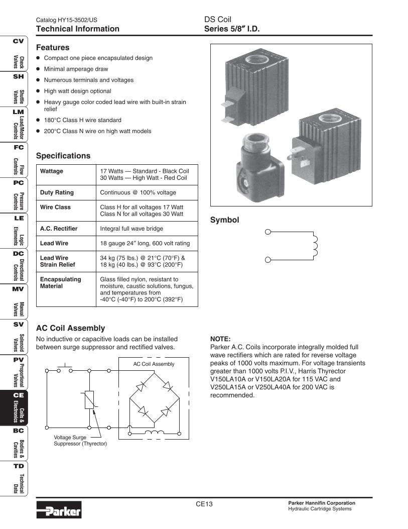
Wattage 17 Watts — Standard - Black Coil30 Watts — High Watt - Red Coil
Duty Rating Continuous @ 100% voltage
Wire Class Class H for all voltages 17 WattClass N for all voltages 30 Watt
A.C. Rectifier Integral full wave bridge
Lead Wire 18 gauge 24″ long, 600 volt rating
Lead Wire 34 kg (75 lbs.) @ 21°C (70°F) &Strain Relief 18 kg (40 lbs.) @ 93°C (200°F)
Encapsulating Glass filled nylon, resistant toMaterial moisture, caustic solutions, fungus,
and temperatures from-40°C (-40°F) to 200°C (392°F)
AC Coil AssemblyNo inductive or capacitive loads can be installedbetween surge suppressor and rectified valves.
NOTE:Parker A.C. Coils incorporate integrally molded fullwave rectifiers which are rated for reverse voltagepeaks of 1000 volts maximum. For voltage transientsgreater than 1000 volts P.I.V., Harris ThyrectorV150LA10A or V150LA20A for 115 VAC andV250LA15A or V250LA40A for 200 VAC isrecommended.
Symbol
Features• Compact one piece encapsulated design
• Minimal amperage draw
• Numerous terminals and voltages
• High watt design optional
• Heavy gauge color coded lead wire with built-in strainrelief
• 180°C Class H wire standard
• 200°C Class N wire on high watt models
AC Coil Assembly
Voltage SurgeSuppressor (Thyrector)
CE14
DS CoilSeries 5/8″″″″″ I.D.
Catalog HY15-3502/US
Parker Hannifin CorporationHydraulic Cartridge Systems
Chec
kVa
lves
Shut
tleVa
lves
Load
/Mot
orCo
ntro
lsFl
owCo
ntro
lsPr
essu
reCo
ntro
lsLo
gic
Elem
ents
Dire
ctio
nal
Cont
rols
Man
ual
Valv
esPr
opor
tiona
lVa
lves
Coils
&El
ectro
nics
Tech
nica
lDa
ta
SH
CV
LM
FC
PC
LE
DC
MV
SV
PV
CE
BC
TD
Bodi
es &
Cavi
ties
Sole
noid
Valv
es
Technical Information
Terminal Styles and Dimensions
Coil Part Numbers
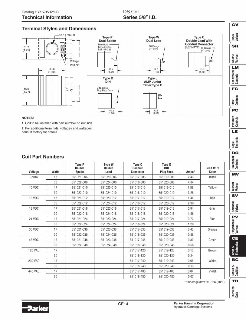
Type P Type W Type C Type DDouble Double Conduit DIN Lead Wire
Voltage Watts Spade Lead Connector Plug Face Amps* Color
6 VDC 17 851021-006 851023-006 851017-006 851019-006 2.43 Black
30 851022-006 851024-006 851018-006 851020-006 4.84
10 VDC 17 851021-010 851023-010 851017-010 851019-010 1.58 Yellow
30 851022-010 851024-010 851018-010 851020-010 3.28
12 VDC 17 851021-012 851023-012 851017-012 851019-012 1.44 Red
30 851022-012 851024-012 851018-012 851020-012 2.30
18 VDC 17 851021-018 851023-018 851017-018 851019-018 0.94 Gray
30 851022-018 851024-018 851018-018 851020-018 1.86
24 VDC 17 851021-024 851023-024 851017-024 851019-024 0.72 Blue
30 851022-024 851024-024 851018-024 851020-024 1.20
36 VDC 17 851021-036 851023-036 851017-036 851019-036 0.43 Orange
30 851022-036 851024-036 851018-036 851020-036 0.88
48 VDC 17 851021-048 851023-048 851017-048 851019-048 0.30 Green
30 851022-048 851024-048 851018-048 851020-048 0.58
120 VAC 17 851017-120 851019-120 0.15 Brown
30 851018-120 851020-120 0.24
230 VAC 17 851017-240 851019-240 0.08 White
30 851018-240 851020-240 0.13
440 VAC 17 851017-480 851019-480 0.04 Violet
30 851018-480 851020-480 0.07
*Amperage draw @ 21°C (70°F)
NOTES:
1. Coil to be installed with part number on nut side.
2. For additional terminals, voltages and wattages,consult factory for details.
40.6(1.60)
45.0(1.77)
16.0 (.63) I.D.
VoltagePart No.
31.7(1.25)
Type CDouble Lead With
Conduit Connector(1/2" NPTF)
42.2(1.66)
18 Gauge24" Long
Type DDIN
40.2(1.58)
DIN 43650Plug Face Only
Type WDual Lead
28.6(1.13)
18 Gauge24" Long
Type PDual Spade
38.4(1.51)
Thru HoleTinned BrassSAE 1B-0.25
Type JAMP Junior
Timer Type C
40.8(1.61)
CE15
Catalog HY15-3502/US DS CoilSeries 1″″″″″ I.D.
Parker Hannifin CorporationHydraulic Cartridge Systems
CheckValves
ShuttleValves
Load/Motor
ControlsFlow
ControlsPressureControls
LogicElem
entsDirectional
ControlsM
anualValves
SolenoidValves
ProportionalValves
Coils &Electronics
Bodies &Cavities
TechnicalData
SH
CV
LM
FC
PC
LE
DC
MV
SV
PV
CE
BC
TD
Technical Information
Specifications
Terminal Styles and Dimensions
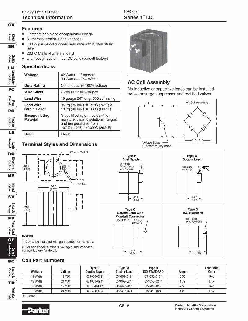
Wattage 42 Watts — Standard30 Watts — Low Watt
Duty Rating Continuous @ 100% voltage
Wire Class Class N for all voltages
Lead Wire 18 gauge 24″ long, 600 volt rating
Lead Wire 34 kg (75 lbs.) @ 21°C (70°F) &Strain Relief 18 kg (40 lbs.) @ 93°C (200°F)
Encapsulating Glass filled nylon, resistant toMaterial moisture, caustic solutions, fungus,
and temperatures from-40°C (-40°F) to 200°C (392°F)
Color Black
Features• Compact one piece encapsulated design
• Numerous terminals and voltages
• Heavy gauge color coded lead wire with built-in strainrelief
• 200°C Class N wire standard
• U.L. recognized on most DC coils (consult factory)
Coil Part Numbers
NOTES:
1. Coil to be installed with part number on nut side.
2. For additional terminals, voltages and wattages,consult factory for details.
Type P Type W Type D Lead WireWattage Voltage Double Spade Double Lead ISO STANDARD Amps Color42 Watts 12 VDC 851060-012* 851062-012* 851058-012* 3.53 Red42 Watts 24 VDC 851060-024* 851062-024* 851058-024* 1.79 Blue30 Watts 12 VDC 853496-012 853497-012 853495-012 2.50 Red30 Watts 24 VDC 853496-024 853497-024 853495-024 1.25 Blue
AC Coil AssemblyNo inductive or capacitive loads can be installedbetween surge suppressor and rectified valves.
AC Coil Assembly
Voltage SurgeSuppressor (Thyrector)
Type DISO Standard
50.6(1.99)
DIN 43650Plug Face Only
Type CDouble Lead With
Conduit Connector(1/2" NPTF)
51.8(2.04)
18 Gauge24" Long
Type WDouble Lead
40.7(1.60)
18 Gauge24" Long
Type PDual Spade
40.7(1.60)
Thru HoleTinned BrassSAE 1B-0.25
25.4 (1.00) I.D.
Voltage
Part No.
48.1(1.89)
56.0(2.20)
59.8(2.35)
*UL Listed
CE16
DS CoilSeries 1″″″″″ I.D.
Catalog HY15-3502/US
Parker Hannifin CorporationHydraulic Cartridge Systems
Chec
kVa
lves
Shut
tleVa
lves
Load
/Mot
orCo
ntro
lsFl
owCo
ntro
lsPr
essu
reCo
ntro
lsLo
gic
Elem
ents
Dire
ctio
nal
Cont
rols
Man
ual
Valv
esPr
opor
tiona
lVa
lves
Coils
&El
ectro
nics
Tech
nica
lDa
ta
SH
CV
LM
FC
PC
LE
DC
MV
SV
PV
CE
BC
TD
Bodi
es &
Cavi
ties
Sole
noid
Valv
es
Notes
Catalog HY15-3502/US
CE17 Parker Hannifin CorporationHydraulic Cartridge Systems
CheckValves
ShuttleValves
Load/Motor
ControlsFlow
ControlsPressureControls
LogicElem
entsDirectional
ControlsM
anualValves
SolenoidValves
ProportionalValves
Coils &Electronics
Bodies &Cavities
TechnicalData
SH
CV
LM
FC
PC
LE
DC
MV
SV
PV
CE
BC
TD
Proportional Valve ControllerSeries XPRO902, 932, 904, 934Technical Information
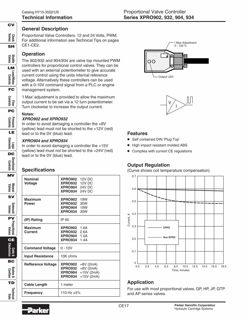
General DescriptionProportional Valve Controllers. 12 and 24 Volts, PWM.For additional information see Technical Tips on pagesCE1-CE2.
OperationThe 902/932 and 904/934 are valve top mounted PWMcontrollers for proportional control valves. They can beused with an external potentiometer to give accuratecurrent control using the units internal referencevoltage. Alternatively these controllers can be usedwith a 0-10V command signal from a PLC or enginemanagement system.
‘I Max’ adjustment is provided to allow the maximumoutput current to be set via a 12 turn potentiometer.Turn clockwise to increase the output current.
Notes:XPRO902 and XPRO932In order to avoid damaging a controller the +8V(yellow) lead must not be shorted to the +12V (red)lead or to the 0V (blue) lead.
XPRO904 and XPRO934In order to avoid damaging a controller the +15V(yellow) lead must not be shorted to the +24V (red)lead or to the 0V (blue) lead.
Specifications
Nominal XPRO902 12V DCVoltage XPRO932 12V DC
XPRO904 24V DCXPRO934 24V DC
Maximum XPRO902 19WPower XPRO932 30W
XPRO904 19WXPRO934 30W
(IP) Rating IP 65
Maximum XPRO902 1.6ACurrent XPRO932 2.6A
XPRO904 1.0AXPRO934 1.4A
Command Voltage 0 - 10V
Input Resistance 10K ohms
Refference Voltage XPRO902 +8V (2mA)XPRO932 +8V (2mA)XPRO904 +15V (2mA)XPRO934 +15V (2mA)
Cable Length 1 meter
Frequency 110 Hz ±5%
Output Regulation(Curve shows coil temperature compensation)
ApplicationFor use with most proportional valves. GP, HP, JP, GTPand AP series valves.
Features• Self contained DIN ‘Plug Top’
• High impact resistant molded ABS
• Complies with current CE regulations
VI
I Max Adjustment0 - 100 %
Output LED
XPRO
Non-XPRO
Cur
rent
, A
0.7
0.1
0.3
0.5
0
0.2
0.4
0.6
Time, minutes0.5 6.54.5 12.5 16.52.5 8.5 10.5 14.5 18.5
Catalog HY15-3502/US Proportional Valve ControllerSeries XPRO902, 932, 904, 934
CE18 Parker Hannifin CorporationHydraulic Cartridge Systems
Chec
kVa
lves
Shut
tleVa
lves
Load
/Mot
orCo
ntro
lsFl
owCo
ntro
lsPr
essu
reCo
ntro
lsLo
gic
Elem
ents
Dire
ctio
nal
Cont
rols
Man
ual
Valv
esPr
opor
tiona
lVa
lves
Coils
&El
ectro
nics
Tech
nica
lDa
ta
SH
CV
LM
FC
PC
LE
DC
MV
SV
PV
CE
BC
TD
Bodi
es &
Cavi
ties
Sole
noid
Valv
es
Technical Information
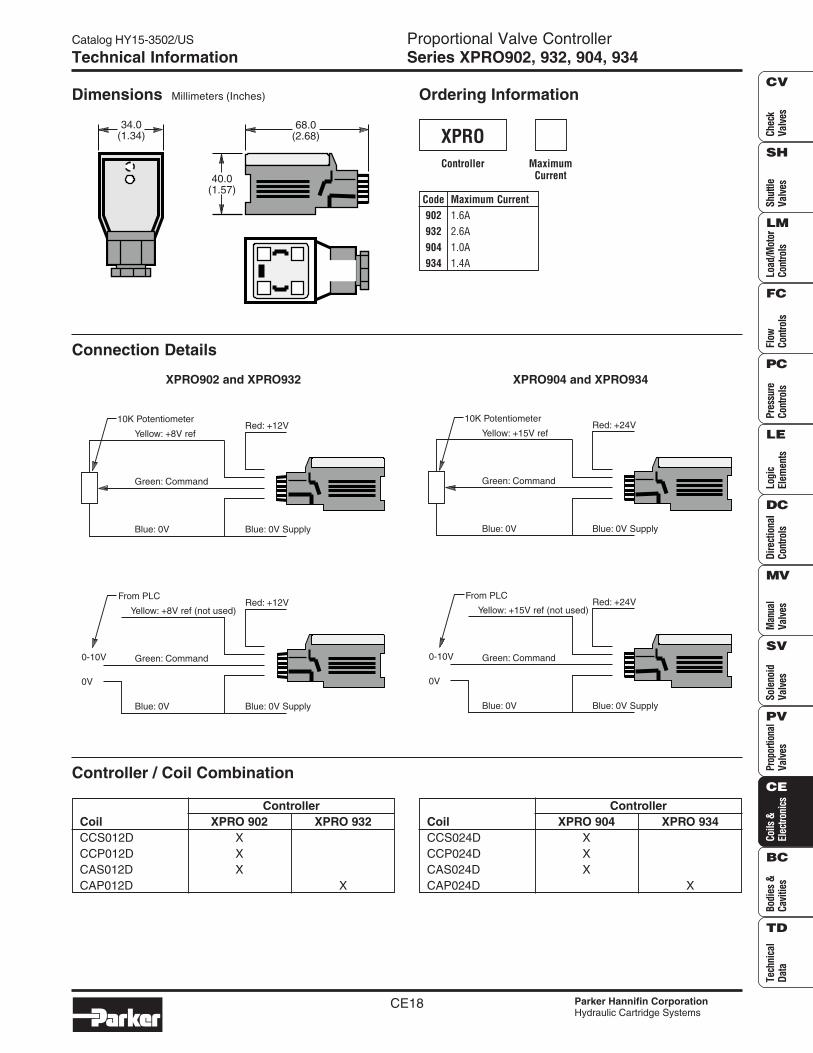
Dimensions Millimeters (Inches) Ordering Information
Code Maximum Current902 1.6A932 2.6A904 1.0A934 1.4A
Controller
XPROMaximum
Current
Connection Details
XPRO902 and XPRO932 XPRO904 and XPRO934
Controller / Coil Combination
ControllerCoil XPRO 902 XPRO 932CCS012D XCCP012D XCAS012D XCAP012D X
ControllerCoil XPRO 904 XPRO 934CCS024D XCCP024D XCAS024D XCAP024D X
68.0(2.68)
40.0(1.57)
34.0(1.34)
Green: Command
Red: +12V
Blue: 0V
Yellow: +8V ref
Blue: 0V Supply
10K Potentiometer
Green: Command
Red: +12V
Blue: 0V
Yellow: +8V ref (not used)
Blue: 0V Supply
From PLC
0-10V
0V
Green: Command
Red: +24V
Blue: 0V
Yellow: +15V ref
Blue: 0V Supply
10K Potentiometer
Green: Command
Red: +24V
Blue: 0V
Yellow: +15V ref (not used)
Blue: 0V Supply
From PLC
0-10V
0V
Catalog HY15-3502/US
CE19 Parker Hannifin CorporationHydraulic Cartridge Systems
CheckValves
ShuttleValves
Load/Motor
ControlsFlow
ControlsPressureControls
LogicElem
entsDirectional
ControlsM
anualValves
SolenoidValves
ProportionalValves
Coils &Electronics
Bodies &Cavities
TechnicalData
SH
CV
LM
FC
PC
LE
DC
MV
SV
PV
CE
BC
TD
Proportional Valve ControllerSeries XPRO902d, 932d, 904d, 934dTechnical Information
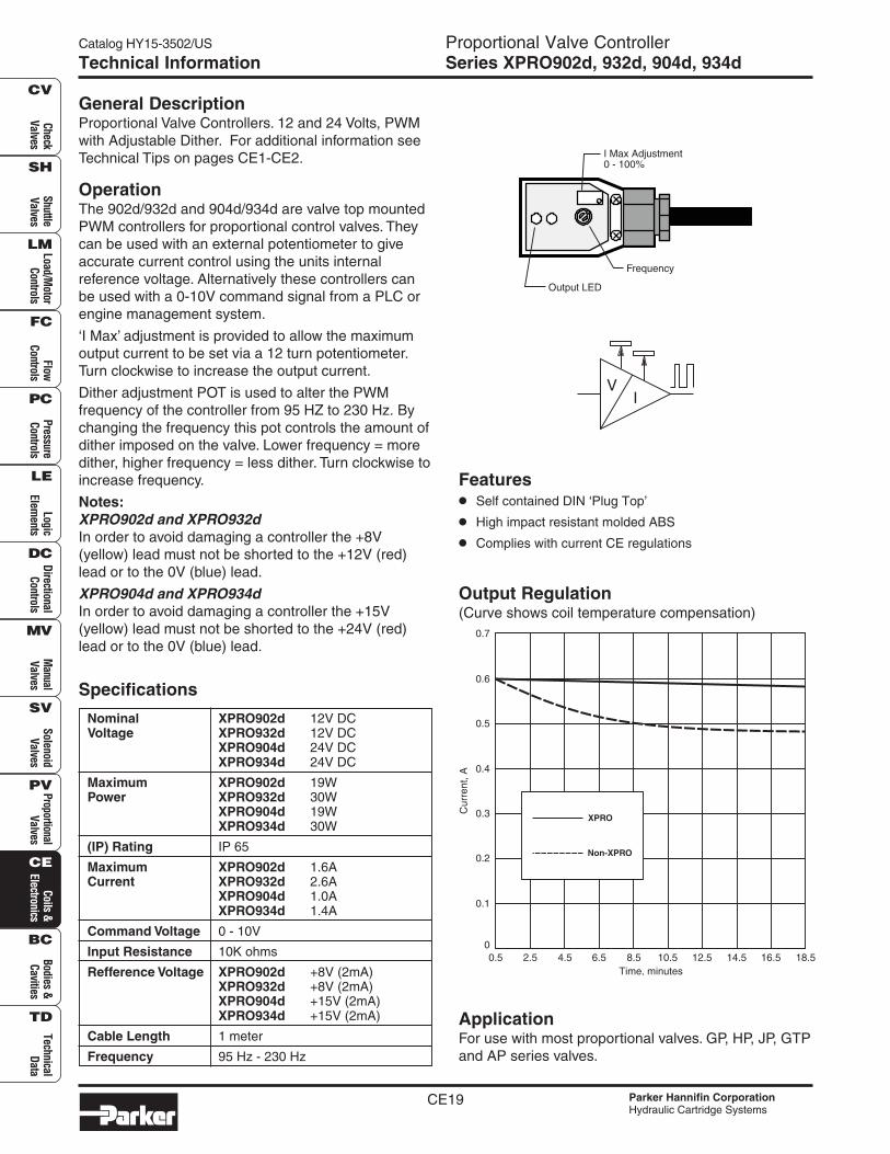
General DescriptionProportional Valve Controllers. 12 and 24 Volts, PWMwith Adjustable Dither. For additional information seeTechnical Tips on pages CE1-CE2.
OperationThe 902d/932d and 904d/934d are valve top mountedPWM controllers for proportional control valves. Theycan be used with an external potentiometer to giveaccurate current control using the units internalreference voltage. Alternatively these controllers canbe used with a 0-10V command signal from a PLC orengine management system.
‘I Max’ adjustment is provided to allow the maximumoutput current to be set via a 12 turn potentiometer.Turn clockwise to increase the output current.
Dither adjustment POT is used to alter the PWMfrequency of the controller from 95 HZ to 230 Hz. Bychanging the frequency this pot controls the amount ofdither imposed on the valve. Lower frequency = moredither, higher frequency = less dither. Turn clockwise toincrease frequency.
Notes:XPRO902d and XPRO932dIn order to avoid damaging a controller the +8V(yellow) lead must not be shorted to the +12V (red)lead or to the 0V (blue) lead.
XPRO904d and XPRO934dIn order to avoid damaging a controller the +15V(yellow) lead must not be shorted to the +24V (red)lead or to the 0V (blue) lead.
Specifications
Nominal XPRO902d 12V DCVoltage XPRO932d 12V DC
XPRO904d 24V DCXPRO934d 24V DC
Maximum XPRO902d 19WPower XPRO932d 30W
XPRO904d 19WXPRO934d 30W
(IP) Rating IP 65
Maximum XPRO902d 1.6ACurrent XPRO932d 2.6A
XPRO904d 1.0AXPRO934d 1.4A
Command Voltage 0 - 10V
Input Resistance 10K ohms
Refference Voltage XPRO902d +8V (2mA)XPRO932d +8V (2mA)XPRO904d +15V (2mA)XPRO934d +15V (2mA)
Cable Length 1 meter
Frequency 95 Hz - 230 Hz
ApplicationFor use with most proportional valves. GP, HP, JP, GTPand AP series valves.
Features• Self contained DIN ‘Plug Top’
• High impact resistant molded ABS
• Complies with current CE regulations
Output Regulation(Curve shows coil temperature compensation)
VI
I Max Adjustment0 - 100%
Frequency
Output LED
XPRO
Non-XPRO
Cur
rent
, A
0.7
0.1
0.3
0.5
0
0.2
0.4
0.6
Time, minutes0.5 6.54.5 12.5 16.52.5 8.5 10.5 14.5 18.5
Catalog HY15-3502/US Proportional Valve ControllerSeries XPRO902d, 932d, 904d, 934d
CE20 Parker Hannifin CorporationHydraulic Cartridge Systems
Chec
kVa
lves
Shut
tleVa
lves
Load
/Mot
orCo
ntro
lsFl
owCo
ntro
lsPr
essu
reCo
ntro
lsLo
gic
Elem
ents
Dire
ctio
nal
Cont
rols
Man
ual
Valv
esPr
opor
tiona
lVa
lves
Coils
&El
ectro
nics
Tech
nica
lDa
ta
SH
CV
LM
FC
PC
LE
DC
MV
SV
PV
CE
BC
TD
Bodi
es &
Cavi
ties
Sole
noid
Valv
es
Technical Information
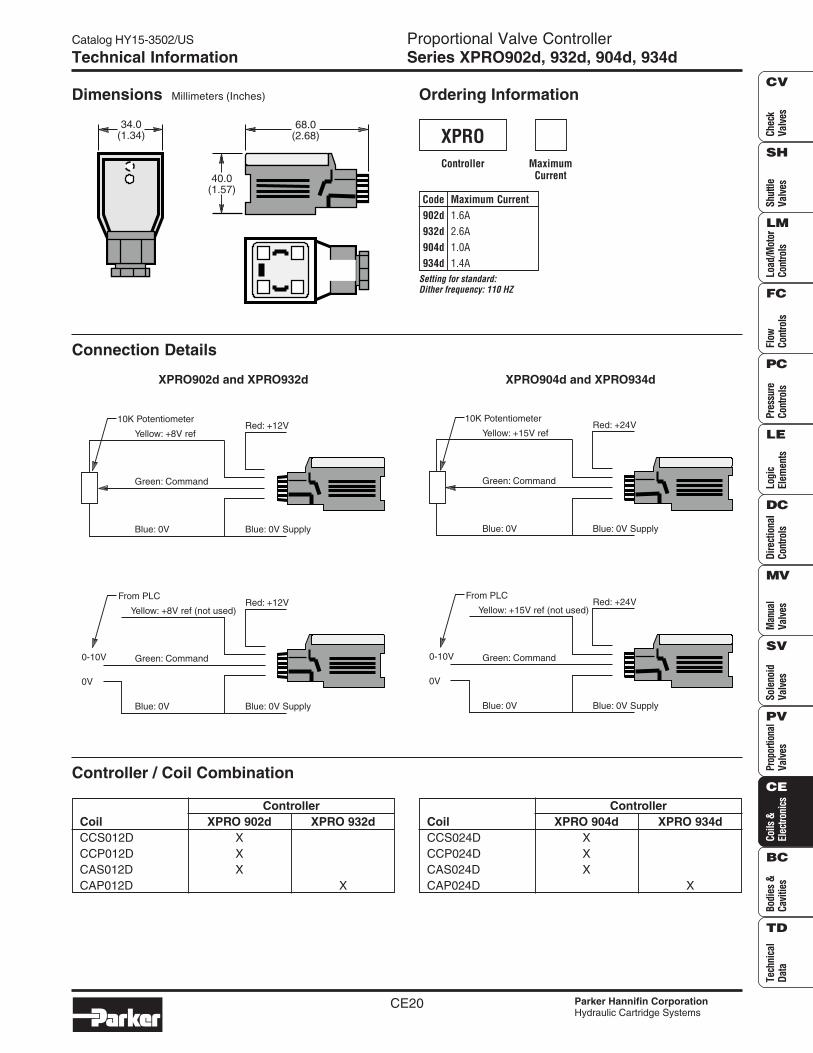
Dimensions Millimeters (Inches) Ordering Information
Code Maximum Current902d 1.6A932d 2.6A904d 1.0A934d 1.4A
Controller
XPROMaximum
Current
Connection Details
XPRO902d and XPRO932d XPRO904d and XPRO934d
Controller / Coil Combination
ControllerCoil XPRO 902d XPRO 932dCCS012D XCCP012D XCAS012D XCAP012D X
ControllerCoil XPRO 904d XPRO 934dCCS024D XCCP024D XCAS024D XCAP024D X
Setting for standard:Dither frequency: 110 HZ
68.0(2.68)
40.0(1.57)
34.0(1.34)
Green: Command
Red: +12V
Blue: 0V
Yellow: +8V ref
Blue: 0V Supply
10K Potentiometer
Green: Command
Red: +12V
Blue: 0V
Yellow: +8V ref (not used)
Blue: 0V Supply
From PLC
0-10V
0V
Green: Command
Red: +24V
Blue: 0V
Yellow: +15V ref
Blue: 0V Supply
10K Potentiometer
Green: Command
Red: +24V
Blue: 0V
Yellow: +15V ref (not used)
Blue: 0V Supply
From PLC
0-10V
0V
Catalog HY15-3502/US
CE21 Parker Hannifin CorporationHydraulic Cartridge Systems
CheckValves
ShuttleValves
Load/Motor
ControlsFlow
ControlsPressureControls
LogicElem
entsDirectional
ControlsM
anualValves
SolenoidValves
ProportionalValves
Coils &Electronics
Bodies &Cavities
TechnicalData
SH
CV
LM
FC
PC
LE
DC
MV
SV
PV
CE
BC
TD
Proportional Valve ControllerSeries XPRO902rid, 932rid, 904rid, 934ridTechnical Information
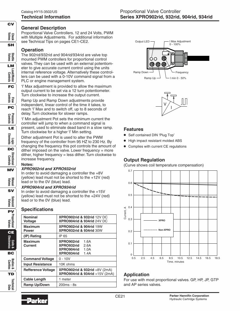
General DescriptionProportional Valve Controllers. 12 and 24 Volts, PWMwith Multiple Adjustments. For additional informationsee Technical Tips on pages CE1-CE2.
OperationThe 902rid/932rid and 904rid/934rid are valve topmounted PWM controllers for proportional controlvalves. They can be used with an external potentiom-eter to give accurate current control using the unitsinternal reference voltage. Alternatively these control-lers can be used with a 0-10V command signal from aPLC or engine management system.‘I’ Max adjustment is provided to allow the maximumoutput current to be set via a 12 turn potentiometer.Turn clockwise to increase the output current.Ramp Up and Ramp Down adjustments provideindependent, linear control of the time it takes, toreach ‘I’ Max and to switch off, up to 8 seconds ofdelay. Turn clockwise for slower ramps.‘I’ Min adjustment Pot sets the minimum current thecontroller will jump to when a command signal ispresent, used to eliminate dead band in a slow ramp.Turn clockwise for a higher ‘I’ Min setting.Dither adjustment Pot is used to alter the PWMfrequency of the controller from 95 HZ to 230 Hz. Bychanging the frequency this pot controls the amount ofdither imposed on the valve. Lower frequency = moredither, higher frequency = less dither. Turn clockwise toincrease frequency.Notes:XPRO902rid and XPRO932ridIn order to avoid damaging a controller the +8V(yellow) lead must not be shorted to the +12V (red)lead or to the 0V (blue) lead.XPRO904rid and XPRO934ridIn order to avoid damaging a controller the +15V(yellow) lead must not be shorted to the +24V (red)lead or to the 0V (blue) lead.
Specifications
Nominal XPRO902rid & 932rid 12V DCVoltage XPRO904rid & 934rid 24V DC
Maximum XPRO902rid & 904rid 19WPower XPRO932rid & 934rid 30W
(IP) Rating IP 65
Maximum XPRO902rid 1.6ACurrent XPRO932rid 2.6A
XPRO904rid 1.0AXPRO934rid 1.4A
Command Voltage 0 - 10V
Input Resistance 10K ohms
Refference Voltage XPRO902rid & 932rid +8V (2mA)XPRO904rid & 934rid +15V (2mA)
Cable Length 1 meter
Ramp Up/Down 200ms - 8s
ApplicationFor use with most proportional valves. GP, HP, JP, GTPand AP series valves.
Features• Self contained DIN ‘Plug Top’
• High impact resistant molded ABS
• Complies with current CE regulations
Output Regulation(Curve shows coil temperature compensation)
VI
I Max Adjustment0 - 100%
Ramp Up
Frequency
I min 0 - 50%
Ramp Down
Output LED
XPRO
Non-XPRO
Cur
rent
, A
0.7
0.1
0.3
0.5
0
0.2
0.4
0.6
Time, minutes0.5 6.54.5 12.5 16.52.5 8.5 10.5 14.5 18.5
Catalog HY15-3502/US Proportional Valve ControllerSeries XPRO902rid, 932rid, 904rid, 934rid
CE22 Parker Hannifin CorporationHydraulic Cartridge Systems
Chec
kVa
lves
Shut
tleVa
lves
Load
/Mot
orCo
ntro
lsFl
owCo
ntro
lsPr
essu
reCo
ntro
lsLo
gic
Elem
ents
Dire
ctio
nal
Cont
rols
Man
ual
Valv
esPr
opor
tiona
lVa
lves
Coils
&El
ectro
nics
Tech
nica
lDa
ta
SH
CV
LM
FC
PC
LE
DC
MV
SV
PV
CE
BC
TD
Bodi
es &
Cavi
ties
Sole
noid
Valv
es
Technical Information
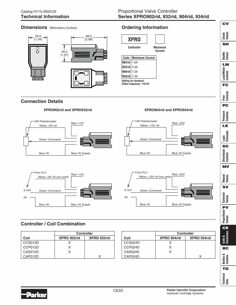
Dimensions Millimeters (Inches) Ordering Information
Code Maximum Current902rid 1.6A932rid 2.6A904rid 1.0A934rid 1.4A
Controller
XPROMaximum
Current
Connection Details
XPRO902rid and XPRO932rid XPRO904rid and XPRO934rid
Controller / Coil Combination
ControllerCoil XPRO 902rid XPRO 932ridCCS012D XCCP012D XCAS012D XCAP012D X
ControllerCoil XPRO 904rid XPRO 934ridCCS024D XCCP024D XCAS024D XCAP024D X
Setting for standard:Dither frequency: 110 HZ
68.0(2.68)
40.0(1.57)
34.0(1.34)
Green: Command
Red: +12V
Blue: 0V
Yellow: +8V ref
Blue: 0V Supply
10K Potentiometer
Green: Command
Red: +12V
Blue: 0V
Yellow: +8V ref (not used)
Blue: 0V Supply
From PLC
0-10V
0V
Green: Command
Red: +24V
Blue: 0V
Yellow: +15V ref
Blue: 0V Supply
10K Potentiometer
Green: Command
Red: +24V
Blue: 0V
Yellow: +15V ref (not used)
Blue: 0V Supply
From PLC
0-10V
0V
Catalog HY15-3502/US
CE23 Parker Hannifin CorporationHydraulic Cartridge Systems
CheckValves
ShuttleValves
Load/Motor
ControlsFlow
ControlsPressureControls
LogicElem
entsDirectional
ControlsM
anualValves
SolenoidValves
ProportionalValves
Coils &Electronics
Bodies &Cavities
TechnicalData
SH
CV
LM
FC
PC
LE
DC
MV
SV
PV
CE
BC
TD
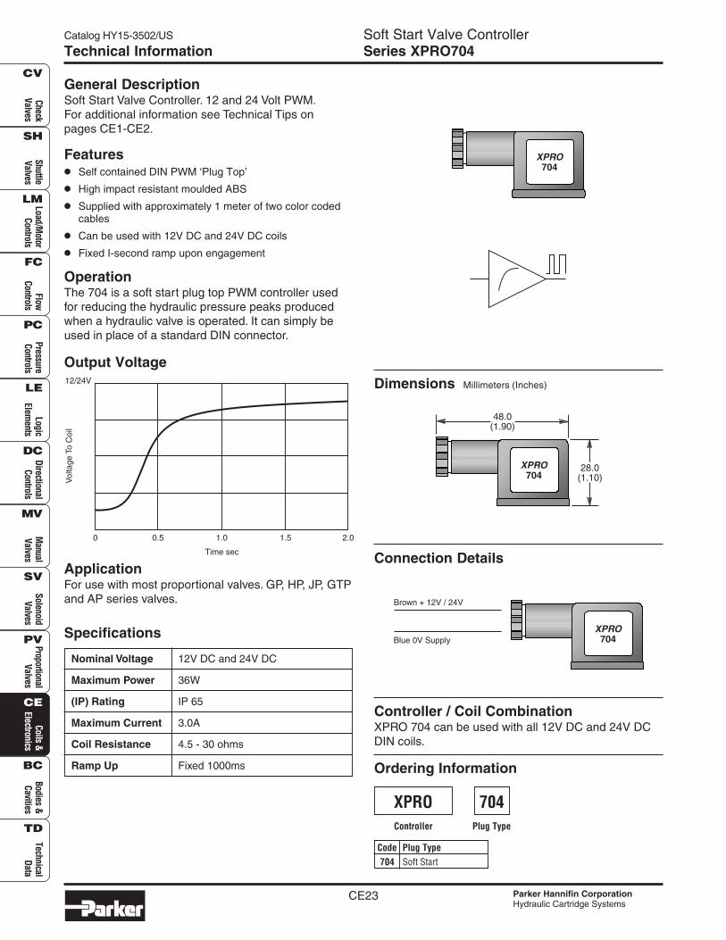
Soft Start Valve ControllerSeries XPRO704Technical Information
General DescriptionSoft Start Valve Controller. 12 and 24 Volt PWM.For additional information see Technical Tips onpages CE1-CE2.
Features• Self contained DIN PWM ‘Plug Top’
• High impact resistant moulded ABS
• Supplied with approximately 1 meter of two color codedcables
• Can be used with 12V DC and 24V DC coils
• Fixed I-second ramp upon engagement
OperationThe 704 is a soft start plug top PWM controller usedfor reducing the hydraulic pressure peaks producedwhen a hydraulic valve is operated. It can simply beused in place of a standard DIN connector.
Specifications
Nominal Voltage 12V DC and 24V DC
Maximum Power 36W
(IP) Rating IP 65
Maximum Current 3.0A
Coil Resistance 4.5 - 30 ohms
Ramp Up Fixed 1000ms
Output Voltage
Controller / Coil CombinationXPRO 704 can be used with all 12V DC and 24V DCDIN coils.
Dimensions Millimeters (Inches)
Ordering Information
Code Plug Type704 Soft Start
Controller
XPROPlug Type
Connection DetailsApplicationFor use with most proportional valves. GP, HP, JP, GTPand AP series valves.
704
XPRO704
XPRO704
48.0(1.90)
28.0(1.10)
XPRO704
Brown + 12V / 24V
Blue 0V Supply
12/24V
Vol
tage
To C
oil
0.5
Time sec
0 1.0 1.5 2.0
Catalog HY15-3502/US Soft Start/Stop Valve ControllerSeries XPRO704b
CE24 Parker Hannifin CorporationHydraulic Cartridge Systems
Chec
kVa
lves
Shut
tleVa
lves
Load
/Mot
orCo
ntro
lsFl
owCo
ntro
lsPr
essu
reCo
ntro
lsLo
gic
Elem
ents
Dire
ctio
nal
Cont
rols
Man
ual
Valv
esPr
opor
tiona
lVa
lves
Coils
&El
ectro
nics
Tech
nica
lDa
ta
SH
CV
LM
FC
PC
LE
DC
MV
SV
PV
CE
BC
TD
Bodi
es &
Cavi
ties
Sole
noid
Valv
es
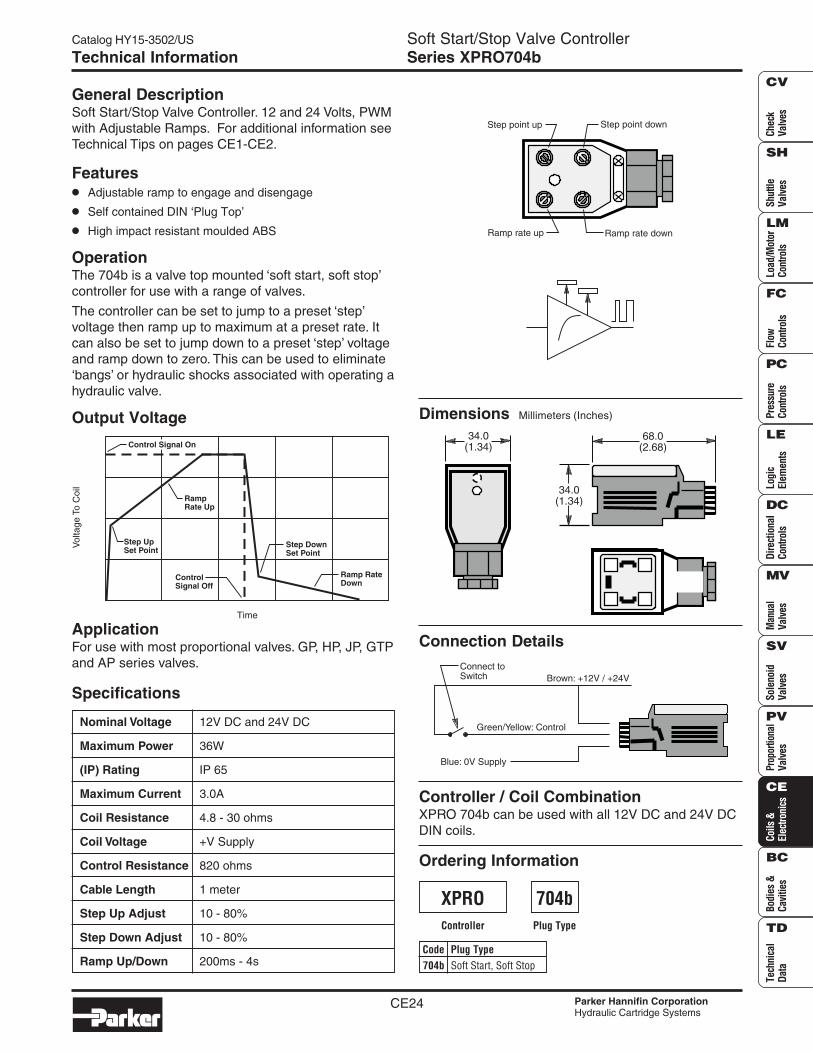
Technical Information
General DescriptionSoft Start/Stop Valve Controller. 12 and 24 Volts, PWMwith Adjustable Ramps. For additional information seeTechnical Tips on pages CE1-CE2.
Features• Adjustable ramp to engage and disengage
• Self contained DIN ‘Plug Top’
• High impact resistant moulded ABS
OperationThe 704b is a valve top mounted ‘soft start, soft stop’controller for use with a range of valves.
The controller can be set to jump to a preset ‘step’voltage then ramp up to maximum at a preset rate. Itcan also be set to jump down to a preset ‘step’ voltageand ramp down to zero. This can be used to eliminate‘bangs’ or hydraulic shocks associated with operating ahydraulic valve.
Specifications
Nominal Voltage 12V DC and 24V DC
Maximum Power 36W
(IP) Rating IP 65
Maximum Current 3.0A
Coil Resistance 4.8 - 30 ohms
Coil Voltage +V Supply
Control Resistance 820 ohms
Cable Length 1 meter
Step Up Adjust 10 - 80%
Step Down Adjust 10 - 80%
Ramp Up/Down 200ms - 4s
Output Voltage
Controller / Coil CombinationXPRO 704b can be used with all 12V DC and 24V DCDIN coils.
Dimensions Millimeters (Inches)
Ordering Information
Code Plug Type704b Soft Start, Soft Stop
Controller
XPROPlug Type
Connection DetailsApplicationFor use with most proportional valves. GP, HP, JP, GTPand AP series valves.
704b
Step point up Step point down
Ramp rate up Ramp rate down
68.0(2.68)
34.0(1.34)
34.0(1.34)
Green/Yellow: Control
Brown: +12V / +24V
Blue: 0V Supply
Connect toSwitch
Vol
tage
To C
oil
Time
RampRate Up
Step UpSet Point
ControlSignal Off
Step DownSet Point
Ramp RateDown
Control Signal On
Catalog HY15-3502/US
CE25 Parker Hannifin CorporationHydraulic Cartridge Systems
CheckValves
ShuttleValves
Load/Motor
ControlsFlow
ControlsPressureControls
LogicElem
entsDirectional
ControlsM
anualValves
SolenoidValves
ProportionalValves
Coils &Electronics
Bodies &Cavities
TechnicalData
SH
CV
LM
FC
PC
LE
DC
MV
SV
PV
CE
BC
TD
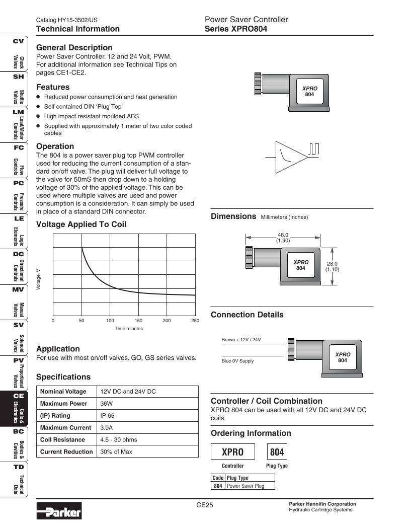
Power Saver ControllerSeries XPRO804Technical Information
General DescriptionPower Saver Controller. 12 and 24 Volt, PWM.For additional information see Technical Tips onpages CE1-CE2.
Features• Reduced power consumption and heat generation
• Self contained DIN ‘Plug Top’
• High impact resistant moulded ABS
• Supplied with approximately 1 meter of two color codedcables
OperationThe 804 is a power saver plug top PWM controllerused for reducing the current consumption of a stan-dard on/off valve. The plug will deliver full voltage tothe valve for 50mS then drop down to a holdingvoltage of 30% of the applied voltage. This can beused where multiple valves are used and powerconsumption is a consideration. It can simply be usedin place of a standard DIN connector.
Specifications
Nominal Voltage 12V DC and 24V DC
Maximum Power 36W
(IP) Rating IP 65
Maximum Current 3.0A
Coil Resistance 4.5 - 30 ohms
Current Reduction 30% of Max
Voltage Applied To Coil
Controller / Coil CombinationXPRO 804 can be used with all 12V DC and 24V DCcoils.
Dimensions Millimeters (Inches)
Ordering Information
Code Plug Type804 Power Saver Plug
Controller
XPROPlug Type
Connection Details
ApplicationFor use with most on/off valves. GO, GS series valves.
804
XPRO804
XPRO804
48.0(1.90)
28.0(1.10)
XPRO804
Brown + 12V / 24V
Blue 0V Supply
Vol
tage
,V
50 100
Time minutes
0 150 200 250

Catalog HY15-3502/US Power Saver ControllerSeries XPRO804
CE26 Parker Hannifin CorporationHydraulic Cartridge Systems
Chec
kVa
lves
Shut
tleVa
lves
Load
/Mot
orCo
ntro
lsFl
owCo
ntro
lsPr
essu
reCo
ntro
lsLo
gic
Elem
ents
Dire
ctio
nal
Cont
rols
Man
ual
Valv
esPr
opor
tiona
lVa
lves
Coils
&El
ectro
nics
Tech
nica
lDa
ta
SH
CV
LM
FC
PC
LE
DC
MV
SV
PV
CE
BC
TD
Bodi
es &
Cavi
ties
Sole
noid
Valv
es
Notes