Embed Size (px)
Citation preview
Catalyst 6500 Series SwiOL-9041-04
C H A P T E R 2
Catalyst 6500 Series Switch SIPs and SSCs OverviewThis chapter describes the SPA interface processors (SIPs) and SPA services cards (SSCs) that are supported on the Catalyst 6500 Series switch and contains the following sections:
• SIP and SSC Support, page 2-1
• Identifying Slots and Subslots for SIPs, SSCs, and SPAs, page 2-2
• Cisco 7600 SIP-200 Overview, page 2-4
• Cisco 7600 SIP-400 Overview, page 2-8
• Cisco 7600-SIP-600 Overview, page 2-9
• Cisco 7600-SSC-400 Overview, page 2-11
SIP and SSC SupportTable 2-1 lists the SIPs and SSCs that are supported on the Catalyst 6500 Series switch.
Note The Description column indicates the aggregate bandwidth supported by the SIP across all subslots, not per SPA subslot.
Table 2-1 SIP Support
SIP Product Number Description
Maximum Number of SPAs
Minimum Cisco IOS Release
Cisco 7600 SIP-200 7600-SIP-200 622-Mbps SPA interface processor
4 12.2(18)SXE
Cisco 7600 SIP-400 7600-SIP-400 2.5-Gbps SPA interface processor
4 12.2(18)SXE
Cisco 7600 SIP-600 7600-SIP-600 1 x 10-Gbps SPA Interface Processor
1 12.2(18)SXF1
1. Support for the Cisco 7600 SIP-600 was removed in Cisco IOS Release 12.2(33)SXH and restored in Cisco IOS Release 12.2(33)SXI and later releases.
Cisco 7600 SSC-400 7600-SSC-400 SPA services carrier 2 12.2(18)SXE2
2-1tch SIP, SSC, and SPA Hardware Installation Guide
Chapter 2 Catalyst 6500 Series Switch SIPs and SSCs Overview Identifying Slots and Subslots for SIPs, SSCs, and SPAs
Checking For Hardware and Software CompatibilityTo check the minimum software requirements of Cisco IOS software with the hardware installed on your router, Cisco maintains the Software Advisor tool on Cisco.com. This tool does not verify whether SIPs or SPAs within a system are compatible, but it does provide the minimum Cisco IOS requirements for individual hardware modules or components.
Note Access to this tool is limited to users with Cisco.com login accounts.
To access Software Advisor, click Login at Cisco.com, type “Software Advisor” in the SEARCH box, and click GO. Click the link for the Software Advisor tool.
Choose a product family or enter a specific product number to search for the minimum supported software release needed for your hardware.
Identifying Slots and Subslots for SIPs, SSCs, and SPAsThis section describes how to specify the physical location of a SIP, SSC, or SPA on the Catalyst 6500 Series switch using the command-line interface (CLI) to configure or monitor those devices.
Note For simplicity, any reference to “SIP” in this section also applies to the SSC.
Specifying the Slot Location for a SIP or SSCThe Catalyst 6500 Series switch supports different chassis models, each of which supports a certain number of chassis slots.
Note The Catalyst 6500 Series switch SIPs are not supported with a Supervisor Engine 1, Supervisor Engine 1A, Supervisor Engine 2, or Supervisor Engine 720-3A.
2-2Catalyst 6500 Series Switch SIP, SSC, and SPA Hardware Installation Guide
OL-9041-04
Chapter 2 Catalyst 6500 Series Switch SIPs and SSCs Overview Identifying Slots and Subslots for SIPs, SSCs, and SPAs
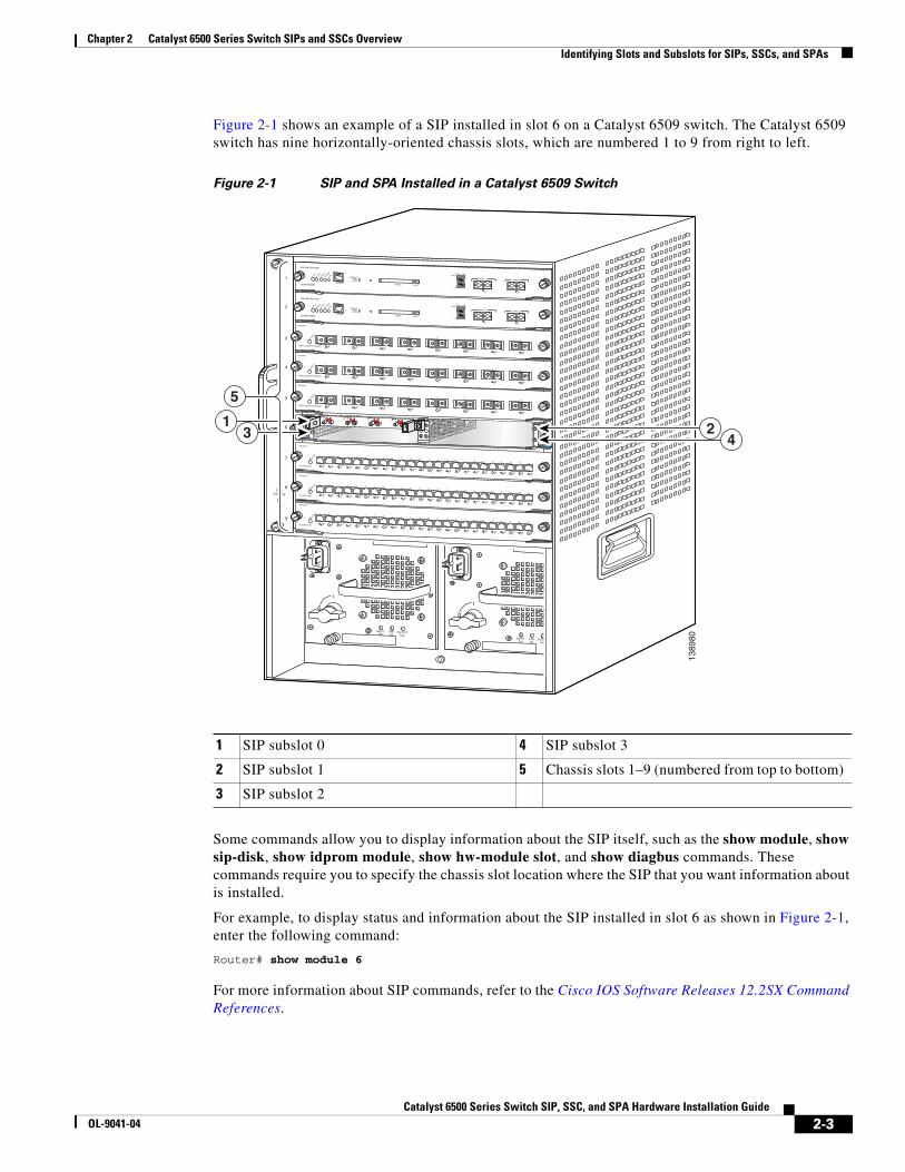
Figure 2-1 shows an example of a SIP installed in slot 6 on a Catalyst 6509 switch. The Catalyst 6509 switch has nine horizontally-oriented chassis slots, which are numbered 1 to 9 from right to left.
Figure 2-1 SIP and SPA Installed in a Catalyst 6509 Switch
Some commands allow you to display information about the SIP itself, such as the show module, show sip-disk, show idprom module, show hw-module slot, and show diagbus commands. These commands require you to specify the chassis slot location where the SIP that you want information about is installed.
For example, to display status and information about the SIP installed in slot 6 as shown in Figure 2-1, enter the following command:
Router# show module 6
For more information about SIP commands, refer to the Cisco IOS Software Releases 12.2SX Command References.
1 SIP subslot 0 4 SIP subslot 3
2 SIP subslot 1 5 Chassis slots 1–9 (numbered from top to bottom)
3 SIP subslot 2
1389
80
FANSTATUS
INPUTOK
FANOK
OUTPUTFAIL
o
INPUTOK
FANOK
OUTPUTFAIL
o
1
2
3
4
5
6
7
8
9
STATUS
2
0
3
1
SPA INTERFACEPROCESSOR
7600-SIP-200
SPA-4XT3/E3
TX RX
A/L0
C/A
TX RX
A/L1
C/A
TX RX
A/L2
C/A
TX RX
A/L3
STATUSC/A
8 PORT GIGABIT ETHERNET
WS-X6408
1
LINK
STATUS 2 3 4 5 6 7 8
LINK
LINK
LINK
LINK
LINK
LINK
LINK
8 PORT GIGABIT ETHERNET
WS-X6408
1
LINK
STATUS 2 3 4 5 6 7 8
LINK
LINK
LINK
LINK
LINK
LINK
LINK
8 PORT GIGABIT ETHERNET
WS-X6408
1
LINK
STATUS 2 3 4 5 6 7 8
LINK
LINK
LINK
LINK
LINK
LINK
LINK
24 PORT 100FX
WS-X6224
STATUS
24 PORT 100FX
WS-X6224
STATUS
24 PORT 100FX
WS-X6224
STATUS
1
LINK
2
LINK
3
LINK
4
LINK
5
LINK
6
LINK
7
LINK
8
LINK
9
LINK
10
LINK
11
LINK
12
LINK
13
LINK
14
LINK
15
LINK
16
LINK
17
LINK
18
LINK
19
LINK
20
LINK
21
LINK
22
LINK
23
LINK
24
LINK
1
LINK
2
LINK
3
LINK
4
LINK
5
LINK
6
LINK
7
LINK
8
LINK
9
LINK
10
LINK
11
LINK
12
LINK
13
LINK
14
LINK
15
LINK
16
LINK
17
LINK
18
LINK
19
LINK
20
LINK
21
LINK
22
LINK
23
LINK
24
LINK
1
LINK
2
LINK
3
LINK
4
LINK
5
LINK
6
LINK
7
LINK
8
LINK
9
LINK
10
LINK
11
LINK
12
LINK
13
LINK
14
LINK
15
LINK
16
LINK
17
LINK
18
LINK
19
LINK
20
LINK
21
LINK
22
LINK
23
LINK
24
LINK
SUPERVISOR2
WS-X6K-SUP2-2GE
STATUS
SYSTEM
CONSOLE
PWR M
GMT
RESET
CONSOLE
CONSOLEPORTMODE
PCMCIA EJECT
PORT 1 PORT 2
Switch Load 100%
1%
LINK
LINK
SUPERVISOR2
WS-X6K-SUP2-2GE
STATUS
SYSTEM
CONSOLE
PWR M
GMT
RESET
CONSOLE
CONSOLEPORTMODE
PCMCIA EJECT
PORT 1 PORT 2
Switch Load 100%
1%
LINK
LINK
13 4
5
2
2-3Catalyst 6500 Series Switch SIP, SSC, and SPA Hardware Installation Guide
OL-9041-04
Chapter 2 Catalyst 6500 Series Switch SIPs and SSCs Overview Cisco 7600 SIP-200 Overview
Specifying the SIP or SSC Subslot Location for a SPASIP subslots begin their numbering with 0 and have a horizontal or vertical orientation depending on the orientation of the SIP in the router chassis slot, as shown in the “SIP, SSC, and SPA Product Overview” chapter of the Catalyst 6500 Series Switch SIP, SSC, and SPA Software Configuration Guide.
Figure 2-1 shows an example of a Cisco 7600 SIP-200 installed with a vertical orientation on a Cisco 7609 router. The Cisco 7600 SIP-200 supports four subslots for the installation of SPAs. In this example, the subslot locations are oriented vertically as follows:
• SIP subslot 0—Top–right subslot
• SIP subslot 1—Bottom–right subslot
• SIP subslot 2—Top–left subslot
• SIP subslot 3—Bottom–left subslot
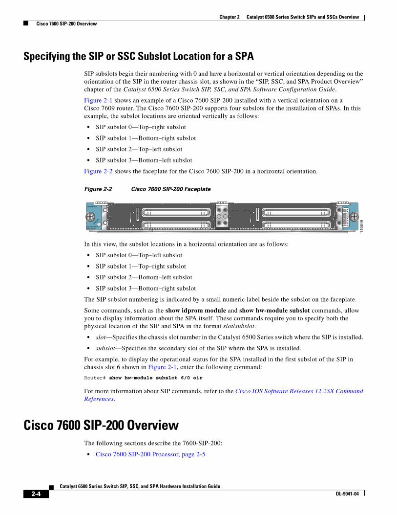
Figure 2-2 shows the faceplate for the Cisco 7600 SIP-200 in a horizontal orientation.
Figure 2-2 Cisco 7600 SIP-200 Faceplate
In this view, the subslot locations in a horizontal orientation are as follows:
• SIP subslot 0—Top–left subslot
• SIP subslot 1—Top–right subslot
• SIP subslot 2—Bottom–left subslot
• SIP subslot 3—Bottom–right subslot
The SIP subslot numbering is indicated by a small numeric label beside the subslot on the faceplate.
Some commands, such as the show idprom module and show hw-module subslot commands, allow you to display information about the SPA itself. These commands require you to specify both the physical location of the SIP and SPA in the format slot/subslot.
• slot—Specifies the chassis slot number in the Catalyst 6500 Series switch where the SIP is installed.
• subslot—Specifies the secondary slot of the SIP where the SPA is installed.
For example, to display the operational status for the SPA installed in the first subslot of the SIP in chassis slot 6 shown in Figure 2-1, enter the following command:
Router# show hw-module subslot 6/0 oir
For more information about SIP commands, refer to the Cisco IOS Software Releases 12.2SX Command References.
Cisco 7600 SIP-200 OverviewThe following sections describe the 7600-SIP-200:
• Cisco 7600 SIP-200 Processor, page 2-5
STATUS
2
0
3
1
SPA INTERFACEPROCESSOR
7600-SIP-200
1168
49
2-4Catalyst 6500 Series Switch SIP, SSC, and SPA Hardware Installation Guide
OL-9041-04
Chapter 2 Catalyst 6500 Series Switch SIPs and SSCs Overview Cisco 7600 SIP-200 Overview
• Cisco 7600 SIP-200 LEDs, page 2-5
• Cisco 7600 SIP-200 Physical Specifications, page 2-6
• Cisco 7600 SIP-200 Memory Options, page 2-6
• Cisco 7600 SIP-200 Default DIP Switch Settings, page 2-7
Cisco 7600 SIP-200 ProcessorTable 2-2 describes the processor on a 7600-SIP-200.
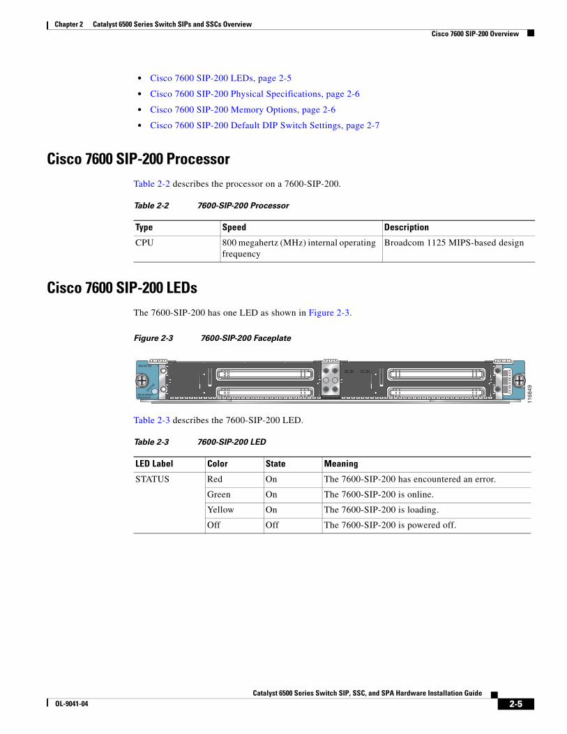
Cisco 7600 SIP-200 LEDsThe 7600-SIP-200 has one LED as shown in Figure 2-3.
Figure 2-3 7600-SIP-200 Faceplate
Table 2-3 describes the 7600-SIP-200 LED.
Table 2-2 7600-SIP-200 Processor
Type Speed Description
CPU 800 megahertz (MHz) internal operating frequency
Broadcom 1125 MIPS-based design
STATUS
2
0
3
1
SPA INTERFACEPROCESSOR
7600-SIP-200
1168
49
Table 2-3 7600-SIP-200 LED
LED Label Color State Meaning
STATUS Red On The 7600-SIP-200 has encountered an error.
Green On The 7600-SIP-200 is online.
Yellow On The 7600-SIP-200 is loading.
Off Off The 7600-SIP-200 is powered off.
2-5Catalyst 6500 Series Switch SIP, SSC, and SPA Hardware Installation Guide
OL-9041-04
Chapter 2 Catalyst 6500 Series Switch SIPs and SSCs Overview Cisco 7600 SIP-200 Overview
Cisco 7600 SIP-200 Physical SpecificationsTable 2-4 describes the 7600-SIP-200 physical specifications.
Cisco 7600 SIP-200 Memory OptionsTable 2-5 lists the memory available for the 7600-SIP-200.
Note The SIP DIMMs must be a matched set. A warning message will appear on the console if the DIMMs on the SIP are different sizes. If the sizes are not the same, the following message will appear at bootup/OIR:
C7600_SIP200-3-MEM_MODULE_MISMATCH: Memory modules are not identical
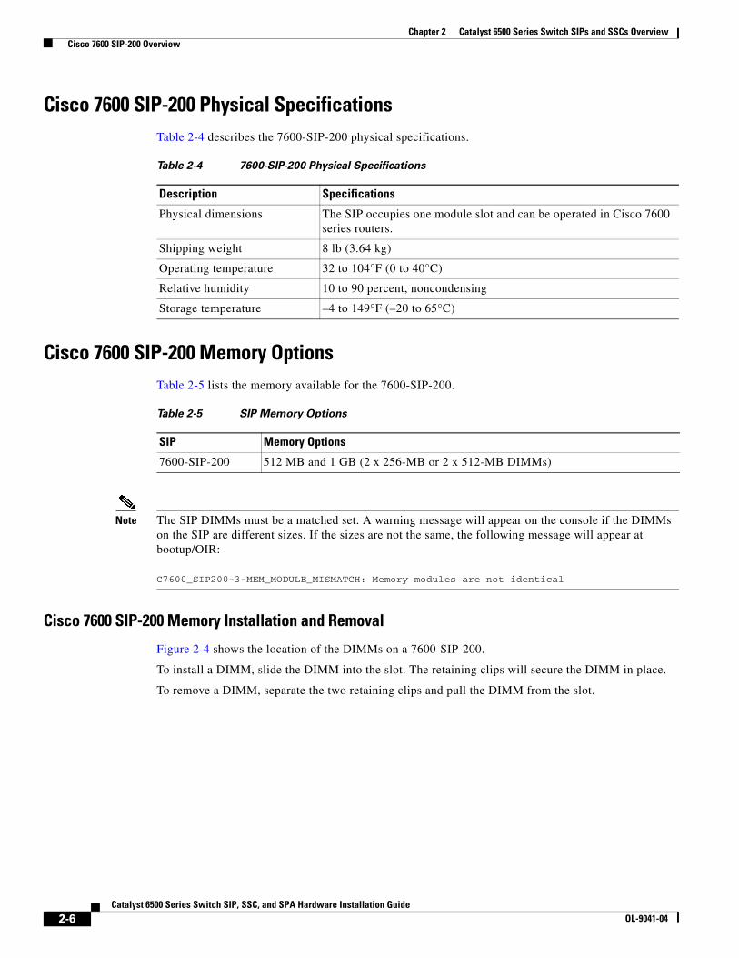
Cisco 7600 SIP-200 Memory Installation and Removal
Figure 2-4 shows the location of the DIMMs on a 7600-SIP-200.
To install a DIMM, slide the DIMM into the slot. The retaining clips will secure the DIMM in place.
To remove a DIMM, separate the two retaining clips and pull the DIMM from the slot.
Table 2-4 7600-SIP-200 Physical Specifications
Description Specifications
Physical dimensions The SIP occupies one module slot and can be operated in Cisco 7600 series routers.
Shipping weight 8 lb (3.64 kg)
Operating temperature 32 to 104°F (0 to 40°C)
Relative humidity 10 to 90 percent, noncondensing
Storage temperature –4 to 149°F (–20 to 65°C)
Table 2-5 SIP Memory Options
SIP Memory Options
7600-SIP-200 512 MB and 1 GB (2 x 256-MB or 2 x 512-MB DIMMs)
2-6Catalyst 6500 Series Switch SIP, SSC, and SPA Hardware Installation Guide
OL-9041-04
Chapter 2 Catalyst 6500 Series Switch SIPs and SSCs Overview Cisco 7600 SIP-200 Overview
Figure 2-4 SIP DIMM Location
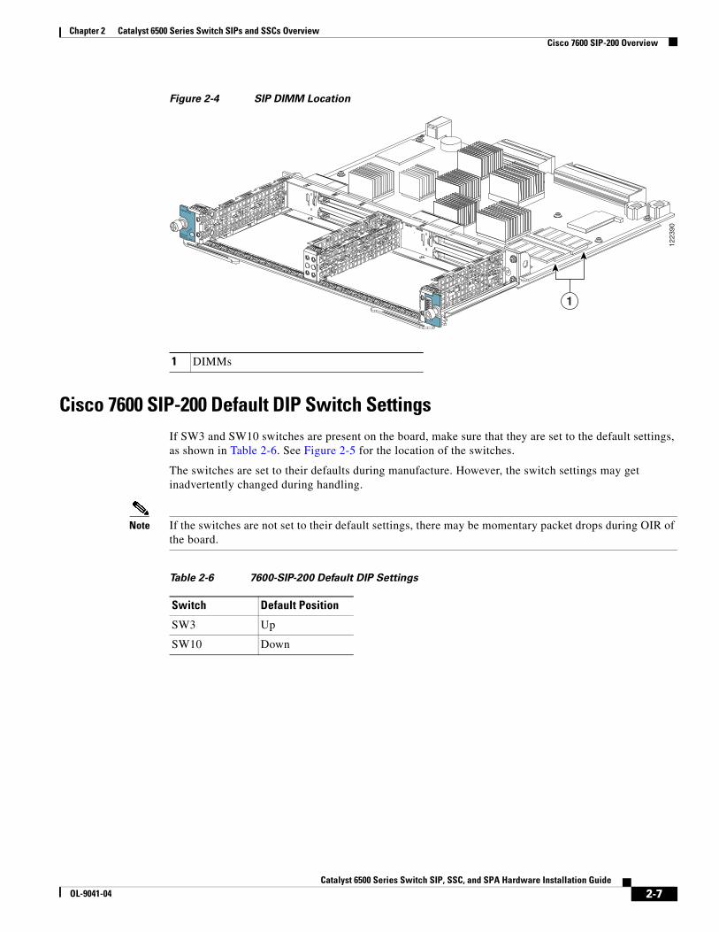
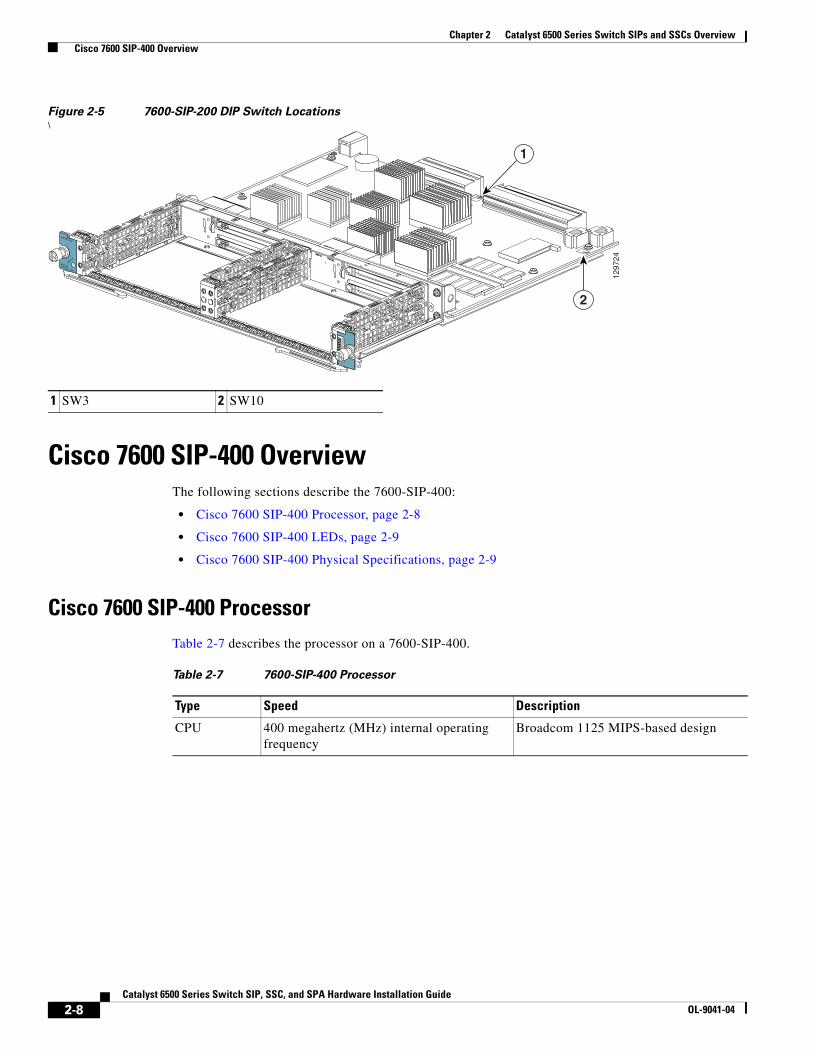
Cisco 7600 SIP-200 Default DIP Switch SettingsIf SW3 and SW10 switches are present on the board, make sure that they are set to the default settings, as shown in Table 2-6. See Figure 2-5 for the location of the switches.
The switches are set to their defaults during manufacture. However, the switch settings may get inadvertently changed during handling.
Note If the switches are not set to their default settings, there may be momentary packet drops during OIR of the board.
1 DIMMs
STATUS
2
0
MODULARSERVICES CARD
7600-MSC-200
1223
90
1
Table 2-6 7600-SIP-200 Default DIP Settings
Switch Default Position
SW3 Up
SW10 Down
2-7Catalyst 6500 Series Switch SIP, SSC, and SPA Hardware Installation Guide
OL-9041-04
Chapter 2 Catalyst 6500 Series Switch SIPs and SSCs Overview Cisco 7600 SIP-400 Overview
Figure 2-5 7600-SIP-200 DIP Switch Locations\
Cisco 7600 SIP-400 OverviewThe following sections describe the 7600-SIP-400:
• Cisco 7600 SIP-400 Processor, page 2-8
• Cisco 7600 SIP-400 LEDs, page 2-9
• Cisco 7600 SIP-400 Physical Specifications, page 2-9
Cisco 7600 SIP-400 ProcessorTable 2-7 describes the processor on a 7600-SIP-400.
1 SW3 2 SW10
STATUS
2
0
MODULARSERVICES CARD
7600-MSC-200
1297
24
1
2
Table 2-7 7600-SIP-400 Processor
Type Speed Description
CPU 400 megahertz (MHz) internal operating frequency
Broadcom 1125 MIPS-based design
2-8Catalyst 6500 Series Switch SIP, SSC, and SPA Hardware Installation Guide
OL-9041-04
Chapter 2 Catalyst 6500 Series Switch SIPs and SSCs Overview Cisco 7600-SIP-600 Overview
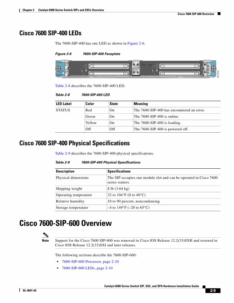
Cisco 7600 SIP-400 LEDsThe 7600-SIP-400 has one LED as shown in Figure 2-6.
Figure 2-6 7600-SIP-400 Faceplate
Table 2-8 describes the 7600-SIP-400 LED.
Cisco 7600 SIP-400 Physical SpecificationsTable 2-9 describes the 7600-SIP-400 physical specifications.
Cisco 7600-SIP-600 Overview
Note Support for the Cisco 7600 SIP-600 was removed in Cisco IOS Release 12.2(33)SXH and restored in Cisco IOS Release 12.2(33)SXI and later releases.
The following sections describe the 7600-SIP-600:
• 7600-SIP-600 Processor, page 2-10
• 7600-SIP-600 LEDs, page 2-10
STATUS
2
0
3
1
SPA INTERFACEPROCESSOR
7600-SIP-400
1013
13
Table 2-8 7600-SIP-400 LED
LED Label Color State Meaning
STATUS Red On The 7600-SIP-400 has encountered an error.
Green On The 7600-SIP-400 is online.
Yellow On The 7600-SIP-400 is loading.
Off Off The 7600-SIP-400 is powered off.
Table 2-9 7600-SIP-400 Physical Specifications
Description Specifications
Physical dimensions The SIP occupies one module slot and can be operated in Cisco 7600 series routers.
Shipping weight 8 lb (3.64 kg)
Operating temperature 32 to 104°F (0 to 40°C)
Relative humidity 10 to 90 percent, noncondensing
Storage temperature –4 to 149°F (–20 to 65°C)
2-9Catalyst 6500 Series Switch SIP, SSC, and SPA Hardware Installation Guide
OL-9041-04
Chapter 2 Catalyst 6500 Series Switch SIPs and SSCs Overview Cisco 7600-SIP-600 Overview
• 7600-SIP-600 Physical Specifications, page 2-10
7600-SIP-600 ProcessorTable 2-13 describes the processor on a 7600-SIP-600.
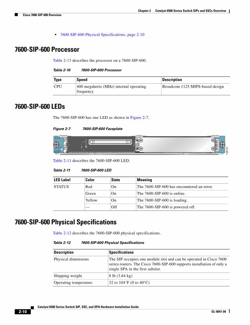
7600-SIP-600 LEDsThe 7600-SIP-600 has one LED as shown in Figure 2-7.
Figure 2-7 7600-SIP-600 Faceplate
Table 2-11 describes the 7600-SIP-600 LED.
7600-SIP-600 Physical SpecificationsTable 2-12 describes the 7600-SIP-600 physical specifications.
Table 2-10 7600-SIP-600 Processor
Type Speed Description
CPU 400 megahertz (MHz) internal operating frequency
Broadcom 1125 MIPS-based design
STATUS
2
0
3
1
SPA INTERFACEPROCESSOR
7600-SIP-600
1381
27
Table 2-11 7600-SIP-600 LED
LED Label Color State Meaning
STATUS Red On The 7600-SIP-600 has encountered an error.
Green On The 7600-SIP-600 is online.
Yellow On The 7600-SIP-600 is loading.
— Off The 7600-SIP-600 is powered off.
Table 2-12 7600-SIP-600 Physical Specifications
Description Specifications
Physical dimensions The SIP occupies one module slot and can be operated in Cisco 7600 series routers. The Cisco 7600-SIP-600 supports installation of only a single SPA in the first subslot.
Shipping weight 8 lb (3.64 kg)
Operating temperature 32 to 104°F (0 to 40°C)
2-10Catalyst 6500 Series Switch SIP, SSC, and SPA Hardware Installation Guide
OL-9041-04
Chapter 2 Catalyst 6500 Series Switch SIPs and SSCs Overview Cisco 7600-SSC-400 Overview
Cisco 7600-SSC-400 OverviewThe following sections describe the SPA services carrier, 7600-SSC-400:
• Cisco 7600 SSC-400 Processor, page 2-11
• Cisco 7600 SSC-400 LED, page 2-11
• Cisco 7600 SSC-400 Physical Specifications, page 2-12
Cisco 7600 SSC-400 ProcessorTable 2-13 describes the processor on a 7600-SSC-400.
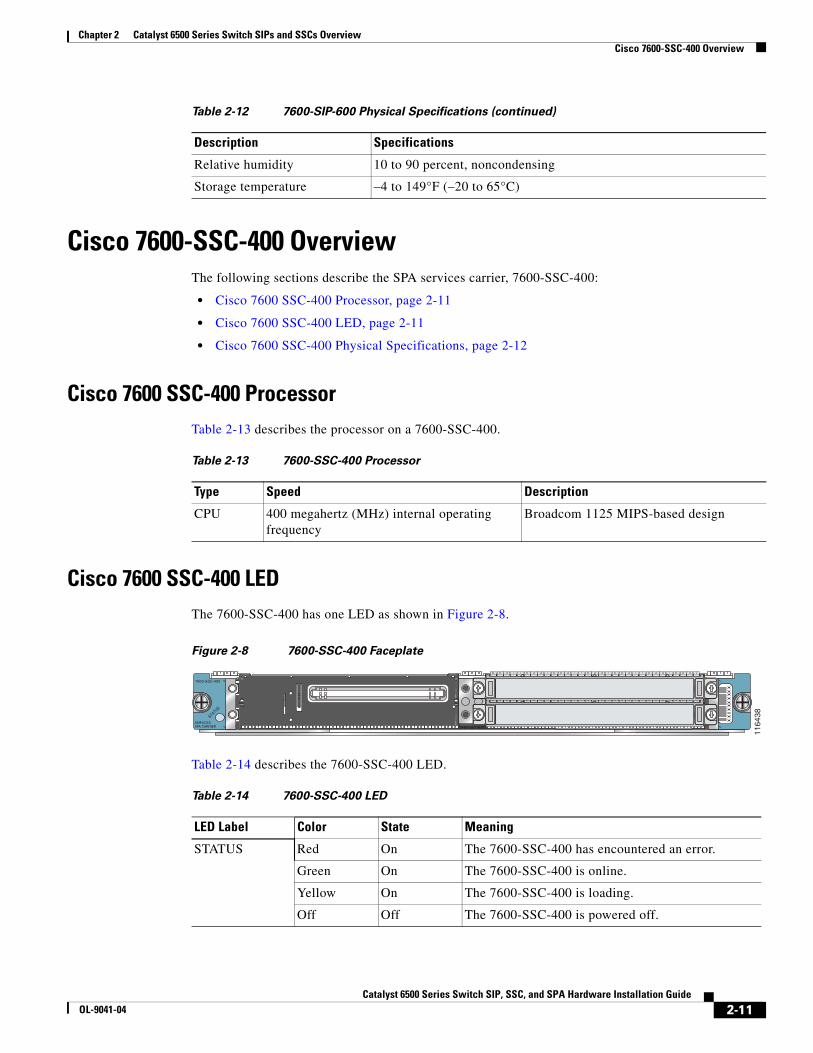
Cisco 7600 SSC-400 LEDThe 7600-SSC-400 has one LED as shown in Figure 2-8.
Figure 2-8 7600-SSC-400 Faceplate
Table 2-14 describes the 7600-SSC-400 LED.
Relative humidity 10 to 90 percent, noncondensing
Storage temperature –4 to 149°F (–20 to 65°C)
Table 2-12 7600-SIP-600 Physical Specifications (continued)
Description Specifications
Table 2-13 7600-SSC-400 Processor
Type Speed Description
CPU 400 megahertz (MHz) internal operating frequency
Broadcom 1125 MIPS-based design
STATUS
2
0
3
1
SERVICESSPA CARRIER
7600-SSC-400
1164
38
Table 2-14 7600-SSC-400 LED
LED Label Color State Meaning
STATUS Red On The 7600-SSC-400 has encountered an error.
Green On The 7600-SSC-400 is online.
Yellow On The 7600-SSC-400 is loading.
Off Off The 7600-SSC-400 is powered off.
2-11Catalyst 6500 Series Switch SIP, SSC, and SPA Hardware Installation Guide
OL-9041-04
Chapter 2 Catalyst 6500 Series Switch SIPs and SSCs Overview Cisco 7600-SSC-400 Overview
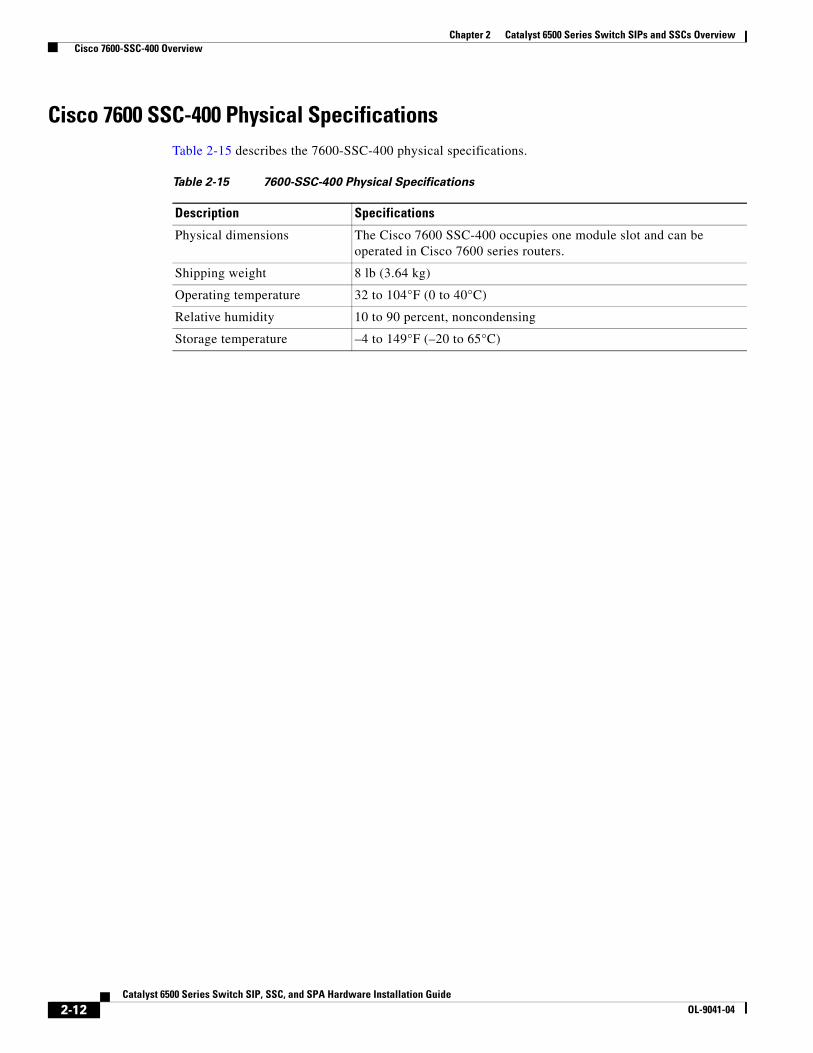
Cisco 7600 SSC-400 Physical SpecificationsTable 2-15 describes the 7600-SSC-400 physical specifications.
Table 2-15 7600-SSC-400 Physical Specifications
Description Specifications
Physical dimensions The Cisco 7600 SSC-400 occupies one module slot and can be operated in Cisco 7600 series routers.
Shipping weight 8 lb (3.64 kg)
Operating temperature 32 to 104°F (0 to 40°C)
Relative humidity 10 to 90 percent, noncondensing
Storage temperature –4 to 149°F (–20 to 65°C)
2-12Catalyst 6500 Series Switch SIP, SSC, and SPA Hardware Installation Guide
OL-9041-04