Embed Size (px)
Citation preview
강릉원주대학교 기계자동차공학부 자동차공학전공 1
Wireframe and
Surface Design
CATIA Training
Online Documents
Version 5 Release 18
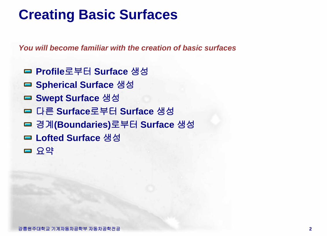
Creating Basic Surfaces
You will become familiar with the creation of basic surfaces
Profile로부터 Surface 생성
Spherical Surface 생성
Swept Surface 생성
다른 Surface로부터 Surface 생성
경계(Boundaries)로부터 Surface 생성
Lofted Surface 생성
요약
강릉원주대학교 기계자동차공학부 자동차공학전공 2
강릉원주대학교 기계자동차공학부 자동차공학전공 3
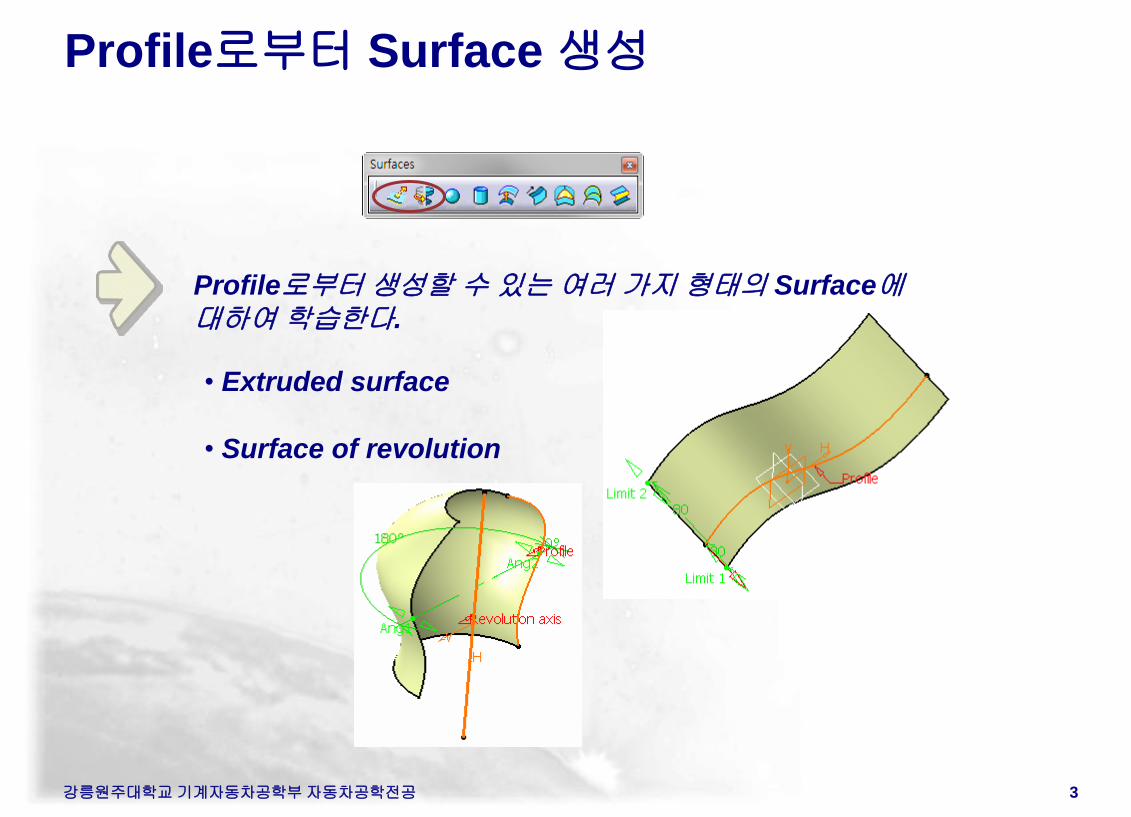
Profile로부터 Surface 생성
Profile로부터 생성할 수 있는 여러 가지 형태의 Surface에
대하여 학습한다.
• Extruded surface
• Surface of revolution
강릉원주대학교 기계자동차공학부 자동차공학전공 4
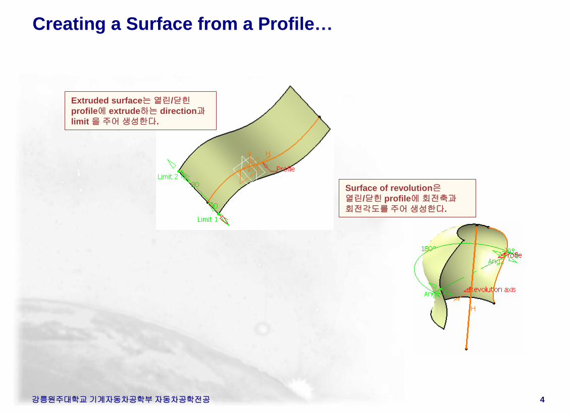
Creating a Surface from a Profile…
Extruded surface는 열린/닫힌
profile에 extrude하는 direction과
limit 을 주어 생성한다.
Surface of revolution은
열린/닫힌 profile에 회전축과
회전각도를 주어 생성한다.
강릉원주대학교 기계자동차공학부 자동차공학전공 5
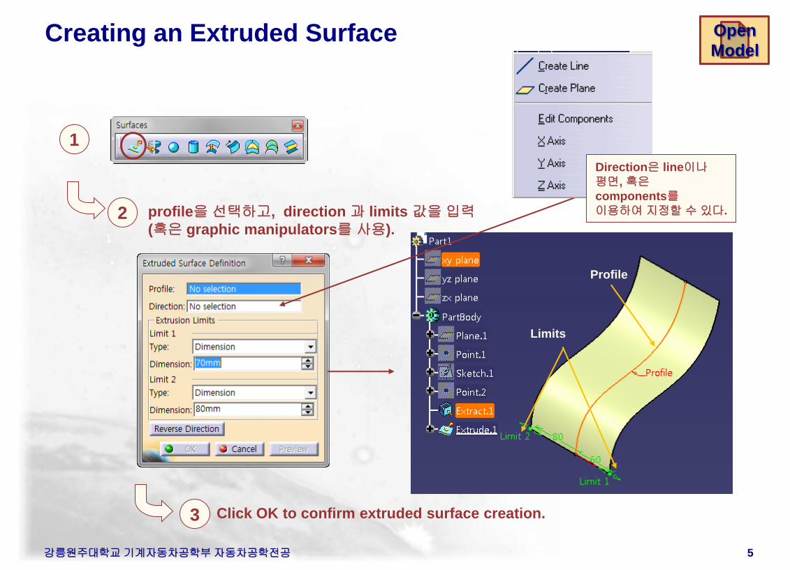
Creating an Extruded Surface
1
2
3
profile을 선택하고, direction 과 limits 값을 입력
(혹은 graphic manipulators를 사용).
Click OK to confirm extruded surface creation.
Profile
Direction은 line이나
평면, 혹은
components를
이용하여 지정할 수 있다.
Limits
Open
Model
강릉원주대학교 기계자동차공학부 자동차공학전공 6
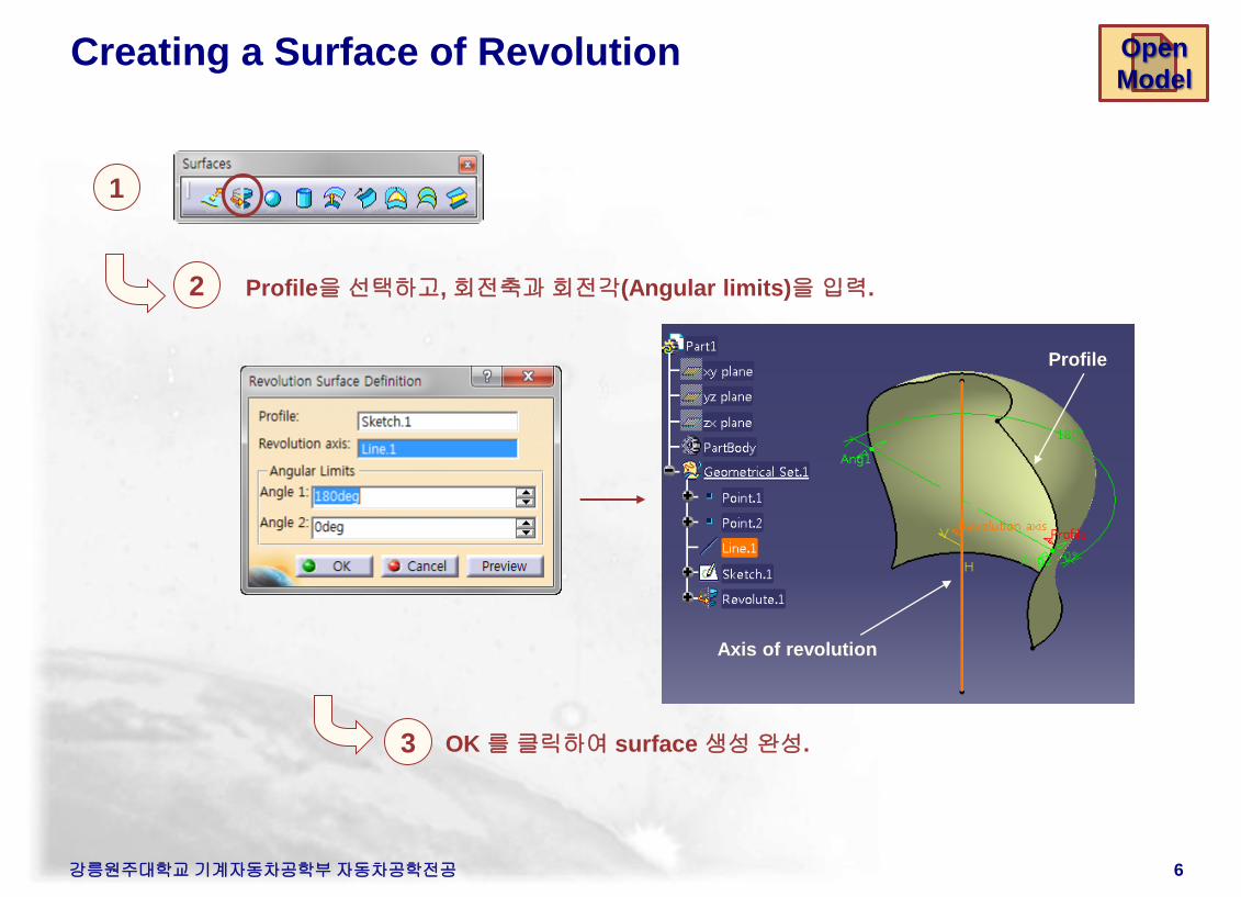
Creating a Surface of Revolution
1
2
3
Profile을 선택하고, 회전축과 회전각(Angular limits)을 입력.
Axis of revolution
Profile
OK 를 클릭하여 surface 생성 완성.
Open
Model
강릉원주대학교 기계자동차공학부 자동차공학전공 7
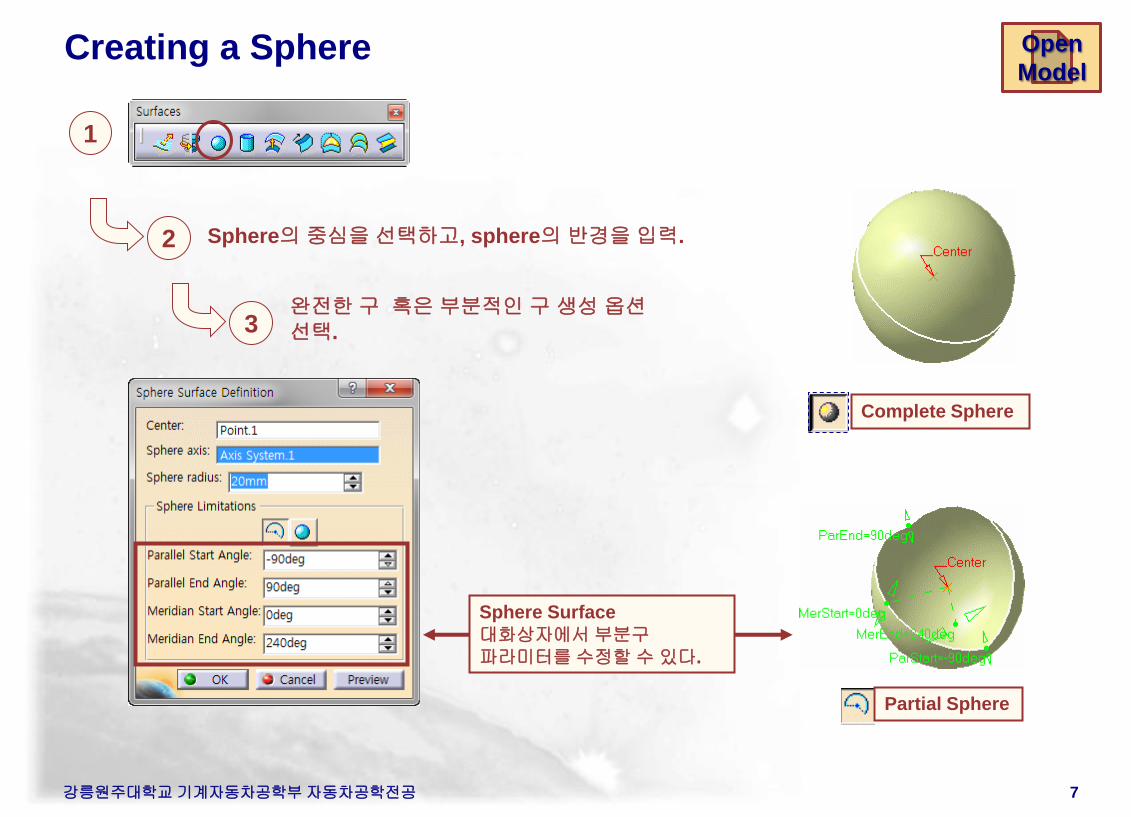
Creating a Sphere
Sphere의 중심을 선택하고, sphere의 반경을 입력.
완전한 구 혹은 부분적인 구 생성 옵션
선택.
Complete Sphere
Partial Sphere
Sphere Surface
대화상자에서 부분구
파라미터를 수정할 수 있다.
1
2
3
Open
Model
강릉원주대학교 기계자동차공학부 자동차공학전공 8
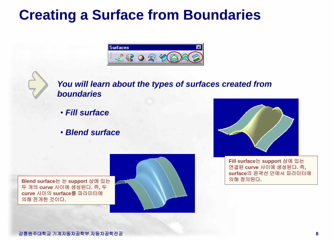
Creating a Surface from Boundaries
You will learn about the types of surfaces created from
boundaries
• Fill surface
• Blend surface
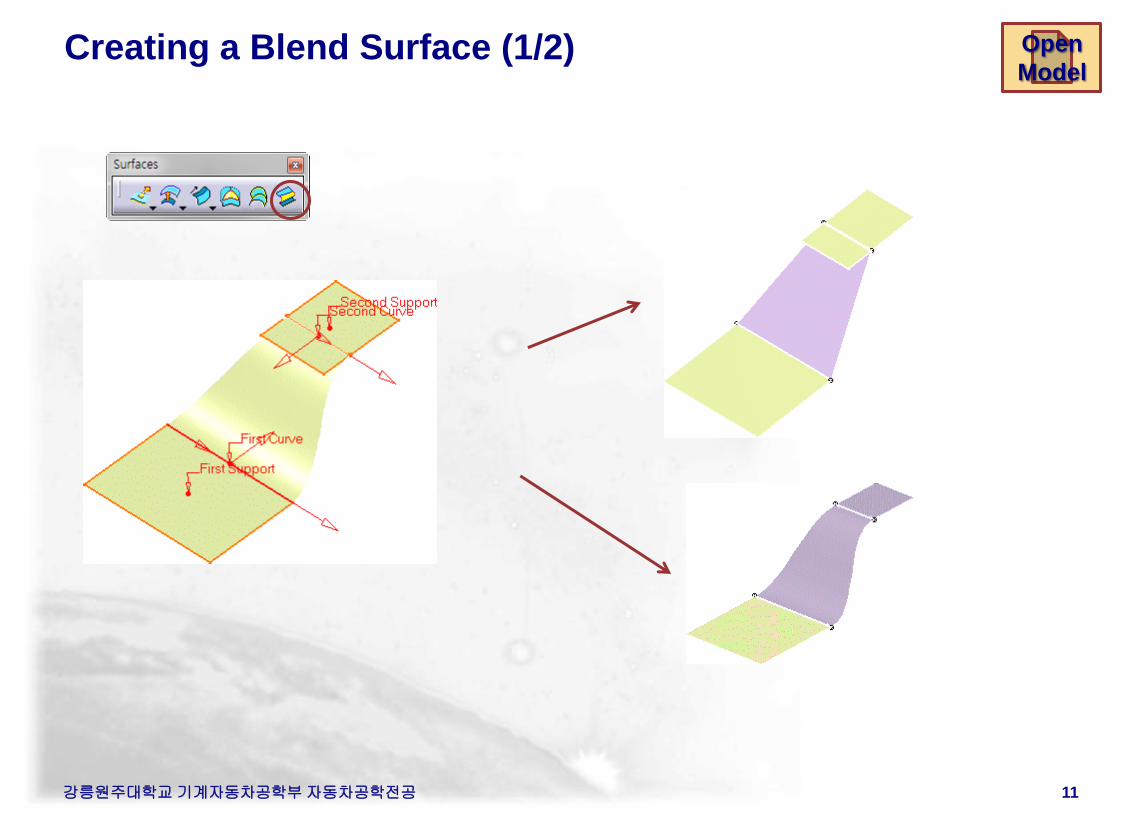
Blend surface는 는 support 상에 있는
두 개의 curve 사이에 생성된다. 즉, 두
curve 사이의 surface를 파라미터에
의해 전개한 것이다.
Fill surface는 support 상에 있는
연결된 curve 사이에 생성된다. 즉,
surface의 윤곽선 안에서 파라미터에
의해 정의된다.
강릉원주대학교 기계자동차공학부 자동차공학전공 9
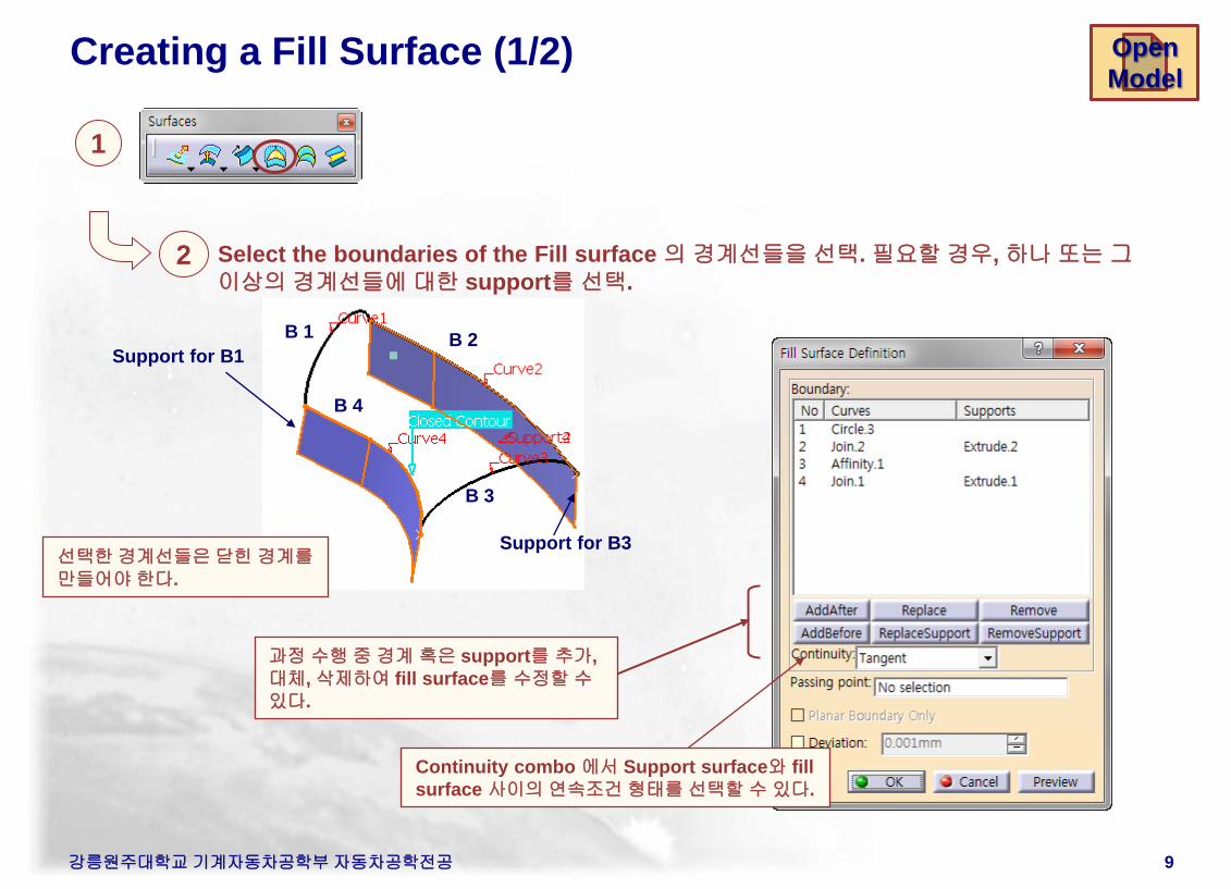
Creating a Fill Surface (1/2)
1
2 Select the boundaries of the Fill surface 의 경계선들을 선택. 필요할 경우, 하나 또는 그
이상의 경계선들에 대한 support를 선택.
B 1
B 3
B 4
Support for B1 B 2
Support for B3 선택한 경계선들은 닫힌 경계를
만들어야 한다.
과정 수행 중 경계 혹은 support를 추가,
대체, 삭제하여 fill surface를 수정할 수
있다.
Continuity combo 에서 Support surface와 fill
surface 사이의 연속조건 형태를 선택할 수 있다.
Open
Model
강릉원주대학교 기계자동차공학부 자동차공학전공 10
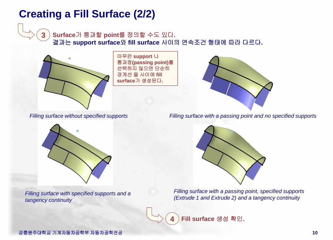
Creating a Fill Surface (2/2)
아무런 support 나
통과점(passing point)를
선택하지 않으면 단순히
경계선 들 사이에 fill
surface가 생성된다.
4 Fill surface 생성 확인.
3 Surface가 통과할 point를 정의할 수도 있다.
결과는 support surface와 fill surface 사이의 연속조건 형태에 따라 다르다.
Filling surface without specified supports Filling surface with a passing point and no specified supports
Filling surface with specified supports and a
tangency continuity
Filling surface with a passing point, specified supports
(Extrude 1 and Extrude 2) and a tangency continuity
강릉원주대학교 기계자동차공학부 자동차공학전공 11
Creating a Blend Surface (1/2) Open
Model
강릉원주대학교 기계자동차공학부 자동차공학전공 12
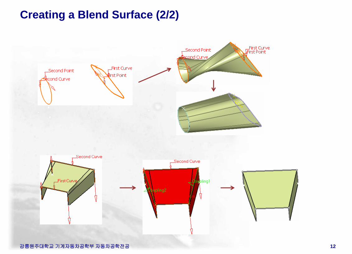
Creating a Blend Surface (2/2)
강릉원주대학교 기계자동차공학부 자동차공학전공 13
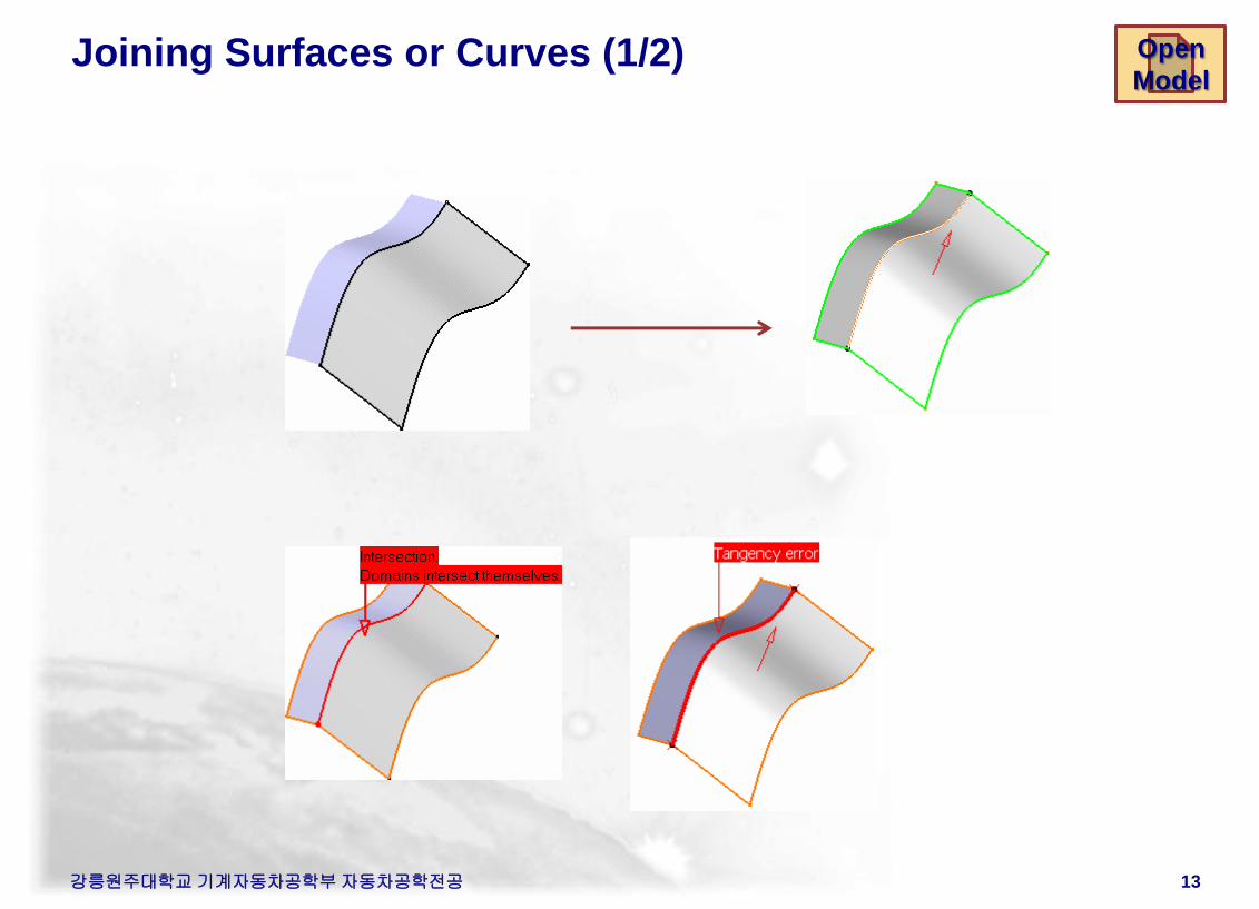
Joining Surfaces or Curves (1/2) Open
Model
강릉원주대학교 기계자동차공학부 자동차공학전공 14
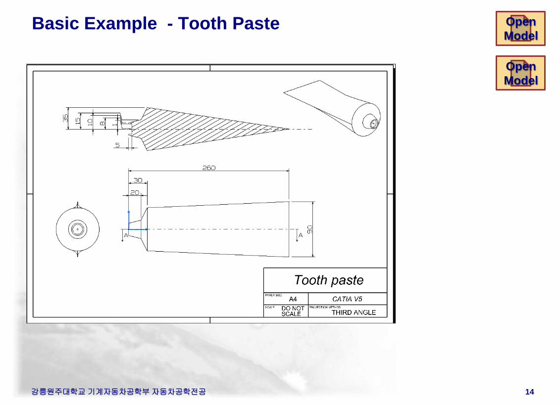
Basic Example - Tooth Paste Open
Model
Open
Model
강릉원주대학교 기계자동차공학부 자동차공학전공
1 2
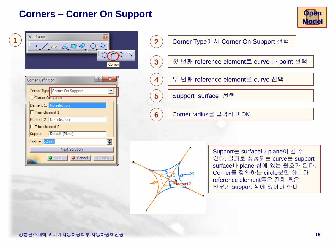
Support는 surface나 plane이 될 수
있다. 결과로 생성되는 curve는 support
surface나 plane 상에 있는 원호가 된다.
Corner를 정의하는 circle뿐만 아니라
reference element들은 전체 혹은
일부가 support 상에 있어야 한다.
Corner Type에서 Corner On Support 선택
Open
Model Corners – Corner On Support
3 첫 번째 reference element로 curve 나 point 선택
4 두 번째 reference element로 curve 선택
5 Support surface 선택
6 Corner radius를 입력하고 OK.
15
Corners – 3D Corner
강릉원주대학교 기계자동차공학부 자동차공학전공
1 2
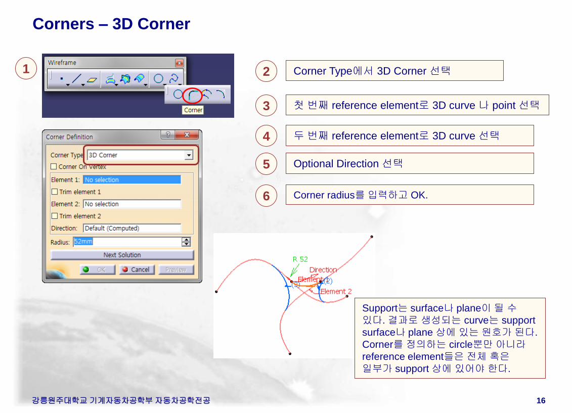
Support는 surface나 plane이 될 수
있다. 결과로 생성되는 curve는 support
surface나 plane 상에 있는 원호가 된다.
Corner를 정의하는 circle뿐만 아니라
reference element들은 전체 혹은
일부가 support 상에 있어야 한다.
Corner Type에서 3D Corner 선택
3 첫 번째 reference element로 3D curve 나 point 선택
4 두 번째 reference element로 3D curve 선택
5 Optional Direction 선택
6 Corner radius를 입력하고 OK.
16
Corners – Corner on a Vertex
강릉원주대학교 기계자동차공학부 자동차공학전공
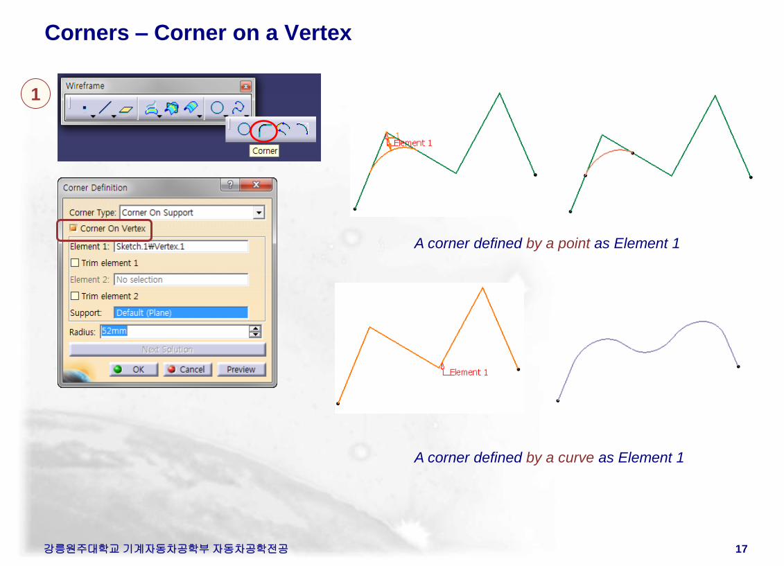
1
17
A corner defined by a point as Element 1
A corner defined by a curve as Element 1
강릉원주대학교 기계자동차공학부 자동차공학전공 18
Shape Fillets
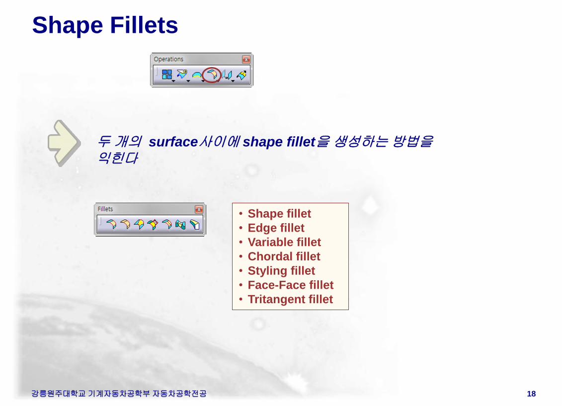
두 개의 surface사이에 shape fillet을 생성하는 방법을
익힌다
• Shape fillet
• Edge fillet
• Variable fillet
• Chordal fillet
• Styling fillet
• Face-Face fillet
• Tritangent fillet
강릉원주대학교 기계자동차공학부 자동차공학전공 19
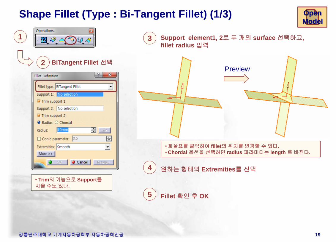
Shape Fillet (Type : Bi-Tangent Fillet) (1/3)
1
2 BiTangent Fillet 선택
3 Support element1, 2로 두 개의 surface 선택하고,
fillet radius 입력
• Trim의 기능으로 Support를
지울 수도 있다.
Open
Model
•화살표를 클릭하여 fillet의 위치를 변경할 수 있다.
• Chordal 옵션을 선택하면 radius 파라미터는 length 로 바뀐다.
Preview
4 원하는 형태의 Extremities를 선택
5 Fillet 확인 후 OK
강릉원주대학교 기계자동차공학부 자동차공학전공 20
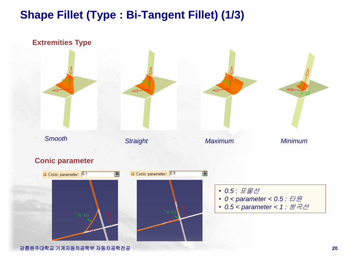
Shape Fillet (Type : Bi-Tangent Fillet) (1/3)
Extremities Type
Maximum Straight Smooth Minimum
Conic parameter
• 0.5 : 포물선
• 0 < parameter < 0.5 : 타원
• 0.5 < parameter < 1 : 쌍곡선
강릉원주대학교 기계자동차공학부 자동차공학전공 21
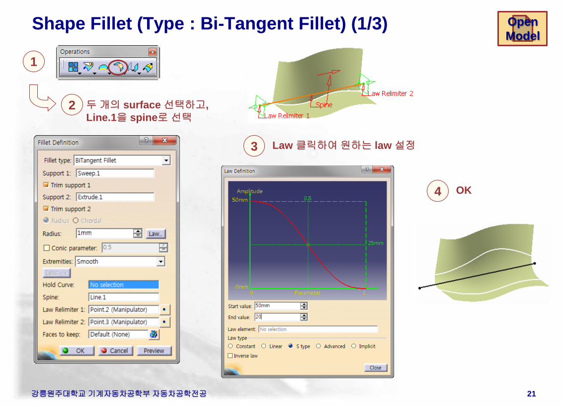
Shape Fillet (Type : Bi-Tangent Fillet) (1/3)
1
2 두 개의 surface 선택하고,
Line.1을 spine로 선택
3 Law 클릭하여 원하는 law 설정
Open
Model
4 OK
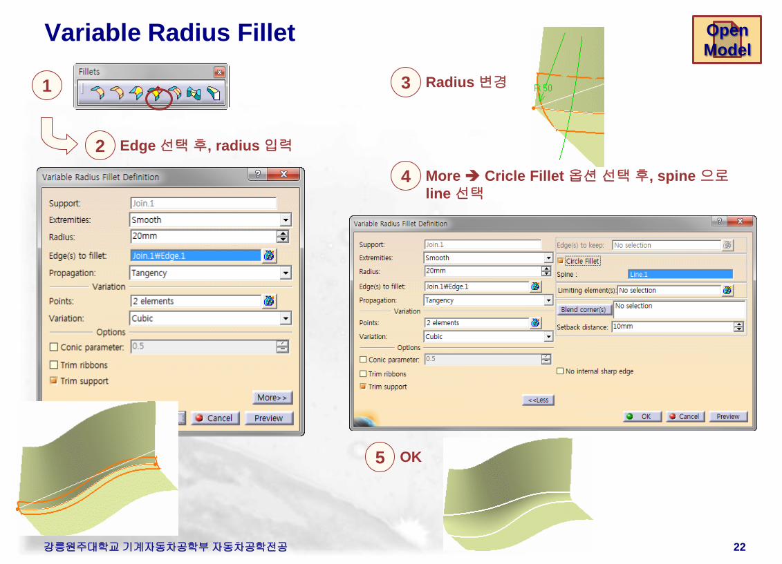
Variable Radius Fillet
강릉원주대학교 기계자동차공학부 자동차공학전공 22
Open
Model
1
2 Edge 선택 후, radius 입력
3 Radius 변경
4 More Cricle Fillet 옵션 선택 후, spine 으로
line 선택
5 OK
강릉원주대학교 기계자동차공학부 자동차공학전공 23
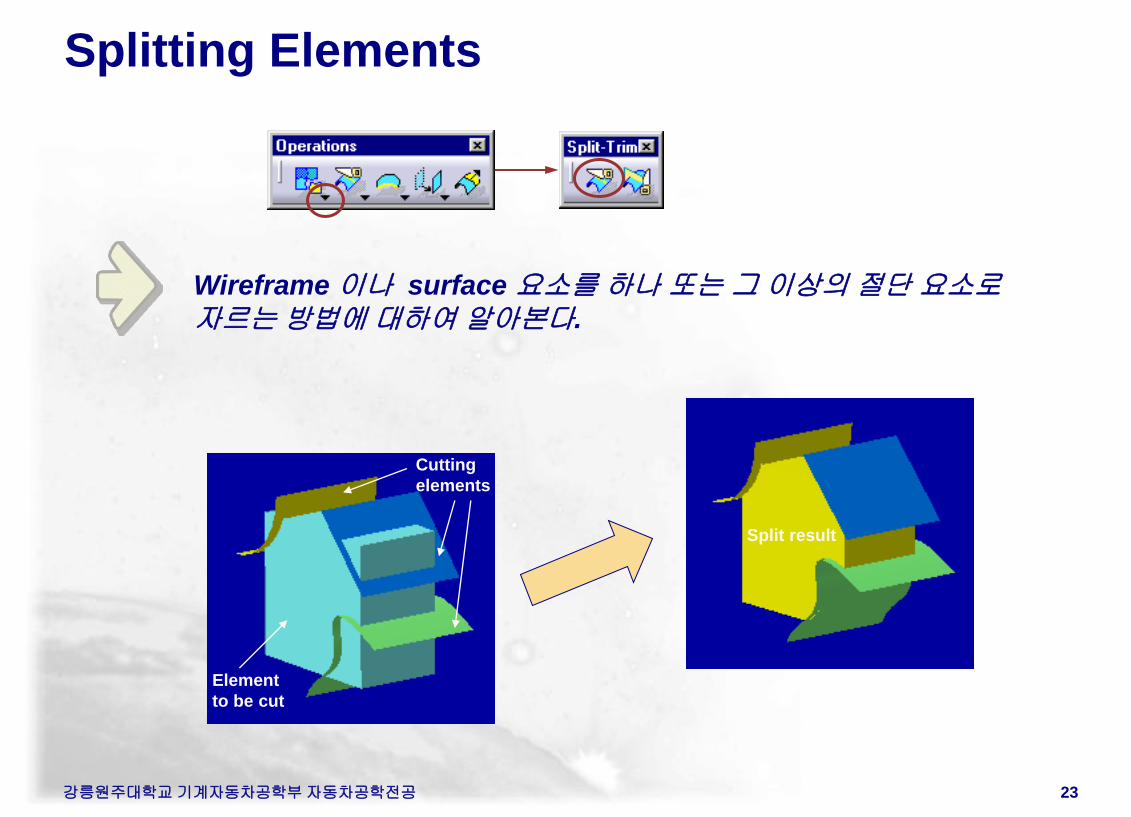
Splitting Elements
Wireframe 이나 surface 요소를 하나 또는 그 이상의 절단 요소로
자르는 방법에 대하여 알아본다.
Cutting
elements
Element
to be cut
Split result
강릉원주대학교 기계자동차공학부 자동차공학전공 24
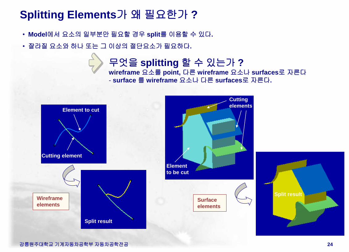
Splitting Elements가 왜 필요한가 ?
무엇을 splitting 할 수 있는가 ? wireframe 요소를 point, 다른 wireframe 요소나 surfaces로 자른다
- surface 를 wireframe 요소나 다른 surfaces로 자른다.
• Model에서 요소의 일부분만 필요할 경우 split를 이용할 수 있다.
• 잘라질 요소와 하나 또는 그 이상의 절단요소가 필요하다.
Element to cut
Cutting element
Split result
Wireframe
elements Surface
elements
Cutting
elements
Element
to be cut
Split result
강릉원주대학교 기계자동차공학부 자동차공학전공 25
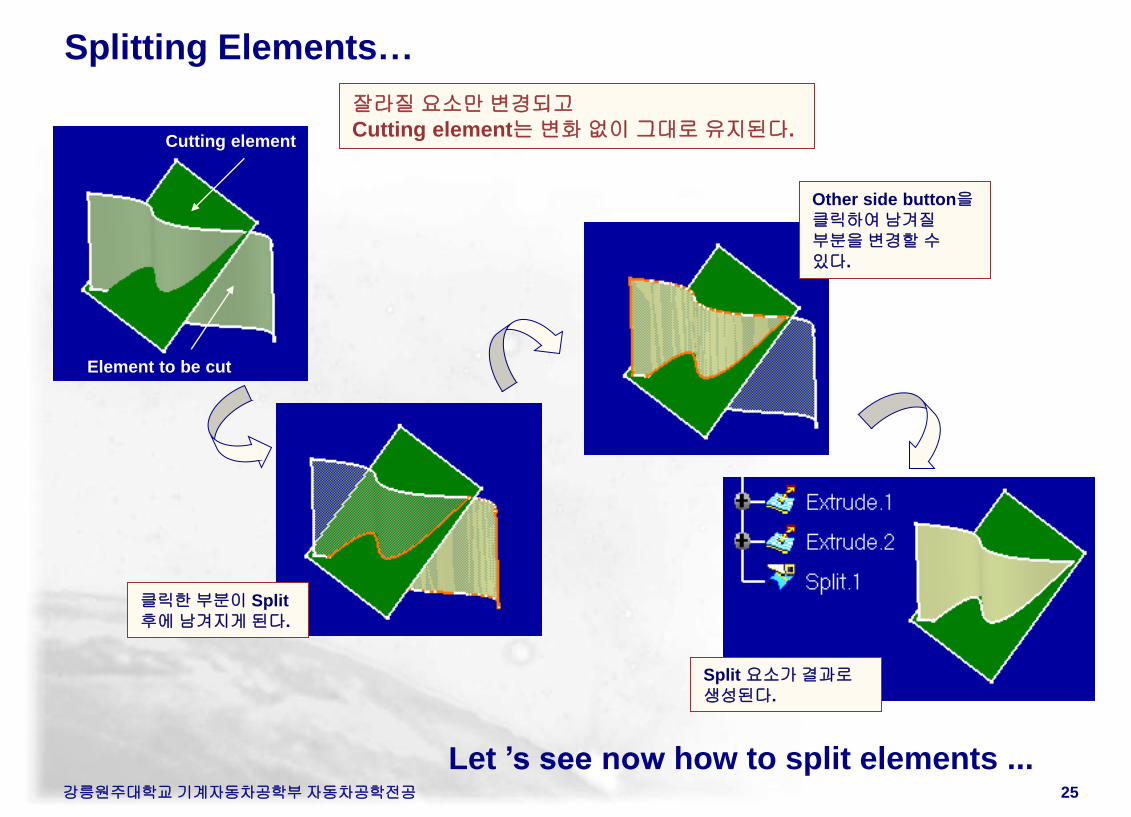
Splitting Elements…
Let ’s see now how to split elements ...
클릭한 부분이 Split
후에 남겨지게 된다.
Other side button을
클릭하여 남겨질
부분을 변경할 수
있다.
Cutting element
Element to be cut
Split 요소가 결과로
생성된다.
잘라질 요소만 변경되고
Cutting element는 변화 없이 그대로 유지된다.
강릉원주대학교 기계자동차공학부 자동차공학전공 26
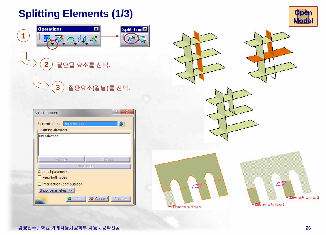
Splitting Elements (1/3)
1
절단될 요소를 선택. 2
절단요소(칼날)를 선택. 3
Open
Model
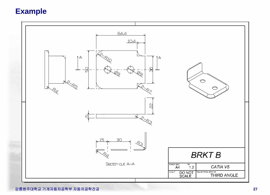
Example
강릉원주대학교 기계자동차공학부 자동차공학전공 27
강릉원주대학교 기계자동차공학부 자동차공학전공 28
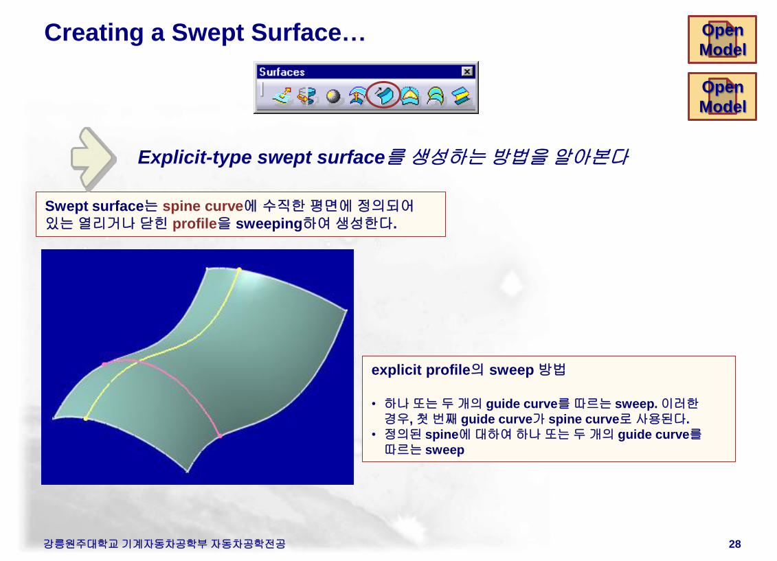
Creating a Swept Surface…
explicit profile의 sweep 방법
• 하나 또는 두 개의 guide curve를 따르는 sweep. 이러한
경우, 첫 번째 guide curve가 spine curve로 사용된다.
• 정의된 spine에 대하여 하나 또는 두 개의 guide curve를
따르는 sweep
Swept surface는 spine curve에 수직한 평면에 정의되어
있는 열리거나 닫힌 profile을 sweeping하여 생성한다.
Explicit-type swept surface를 생성하는 방법을 알아본다
Open
Model
Open
Model
강릉원주대학교 기계자동차공학부 자동차공학전공 29
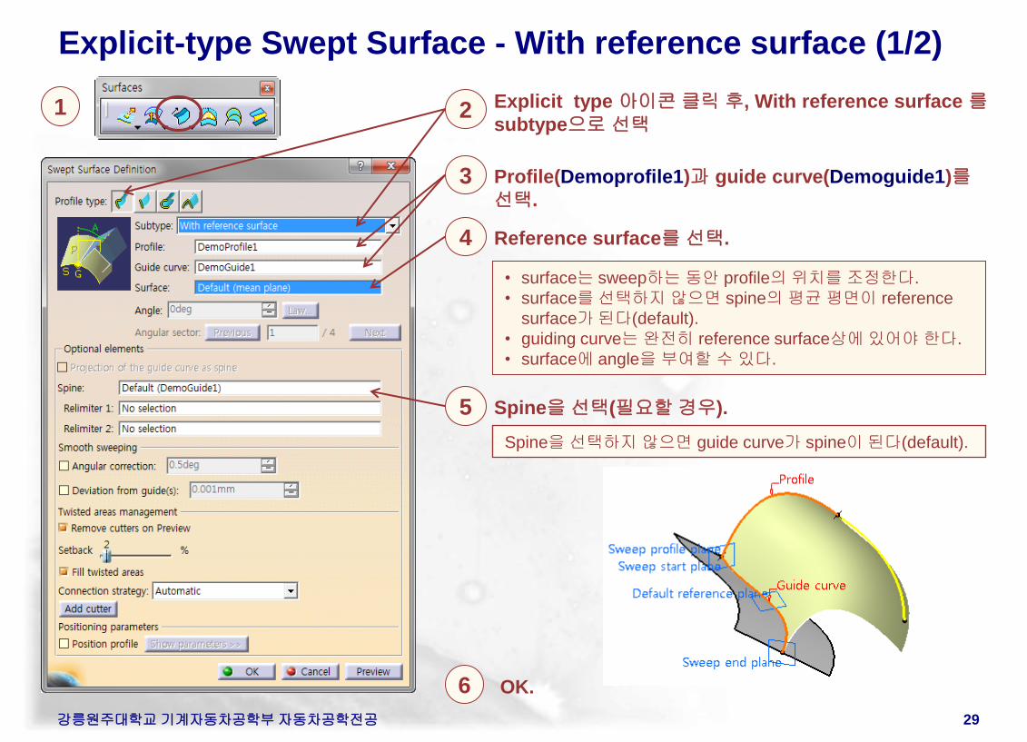
Explicit-type Swept Surface - With reference surface (1/2)
1
3
6 OK.
Profile(Demoprofile1)과 guide curve(Demoguide1)를
선택.
Spine을 선택하지 않으면 guide curve가 spine이 된다(default).
• surface는 sweep하는 동안 profile의 위치를 조정한다.
• surface를 선택하지 않으면 spine의 평균 평면이 reference
surface가 된다(default).
• guiding curve는 완전히 reference surface상에 있어야 한다.
• surface에 angle을 부여할 수 있다.
4 Reference surface를 선택.
2 Explicit type 아이콘 클릭 후, With reference surface 를
subtype으로 선택
5 Spine을 선택(필요할 경우).
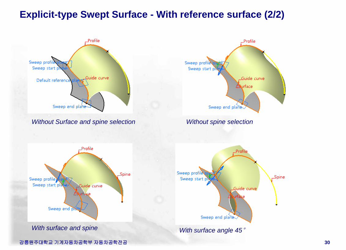
Explicit-type Swept Surface - With reference surface (2/2)
강릉원주대학교 기계자동차공학부 자동차공학전공 30
Without Surface and spine selection Without spine selection
With surface and spine With surface angle 45°
강릉원주대학교 기계자동차공학부 자동차공학전공 31
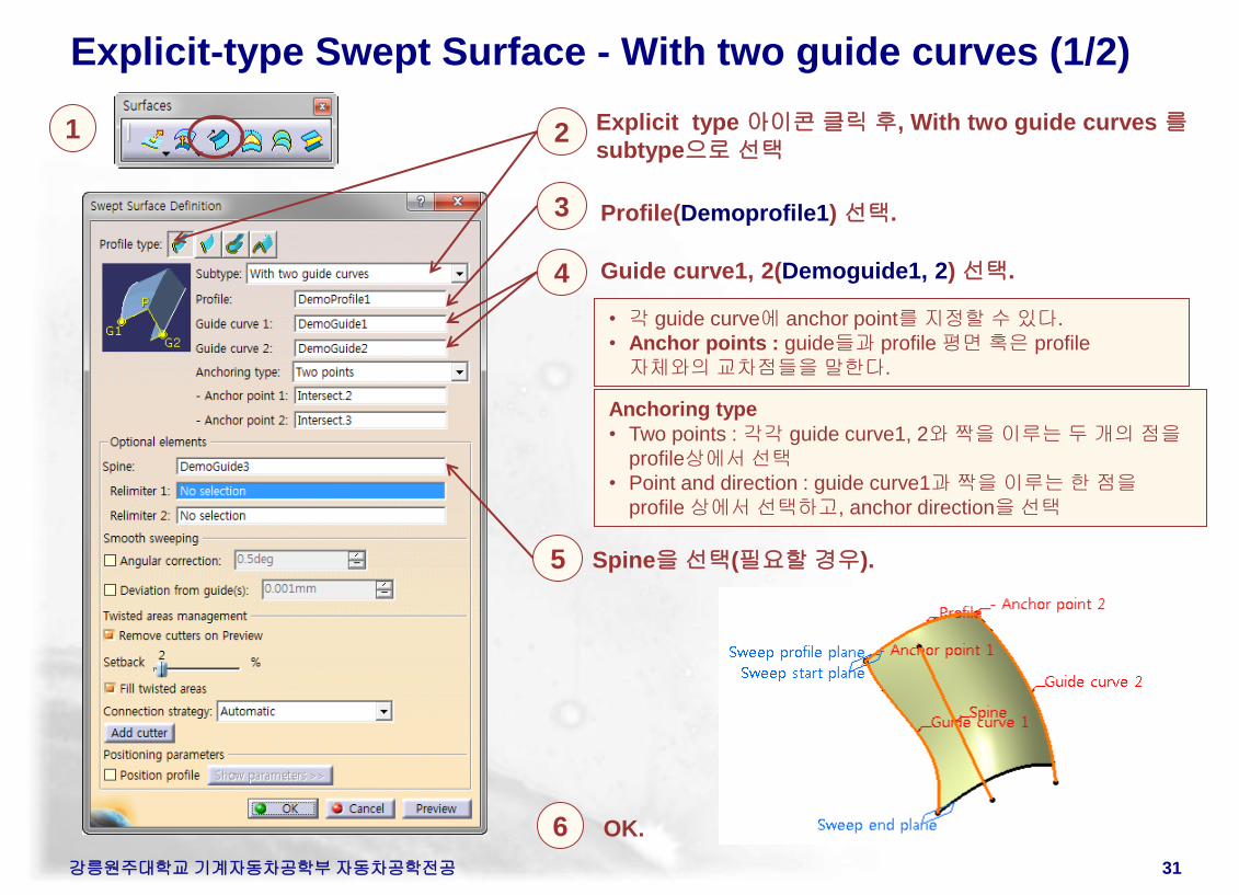
Explicit-type Swept Surface - With two guide curves (1/2)
1
3
6 OK.
Profile(Demoprofile1) 선택.
• 각 guide curve에 anchor point를 지정할 수 있다.
• Anchor points : guide들과 profile 평면 혹은 profile
자체와의 교차점들을 말한다.
4 Guide curve1, 2(Demoguide1, 2) 선택.
2 Explicit type 아이콘 클릭 후, With two guide curves 를
subtype으로 선택
5 Spine을 선택(필요할 경우).
Anchoring type
• Two points : 각각 guide curve1, 2와 짝을 이루는 두 개의 점을
profile상에서 선택
• Point and direction : guide curve1과 짝을 이루는 한 점을
profile 상에서 선택하고, anchor direction을 선택
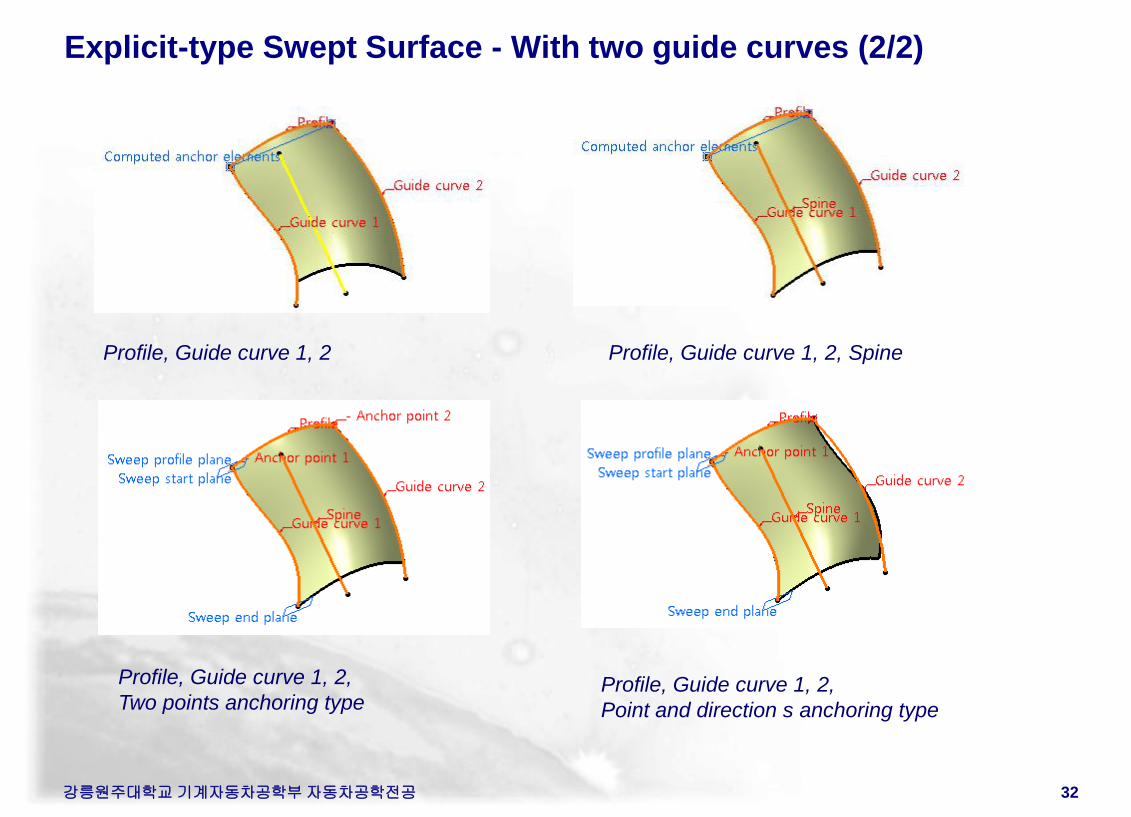
Explicit-type Swept Surface - With two guide curves (2/2)
강릉원주대학교 기계자동차공학부 자동차공학전공 32
Profile, Guide curve 1, 2 Profile, Guide curve 1, 2, Spine
Profile, Guide curve 1, 2,
Two points anchoring type Profile, Guide curve 1, 2,
Point and direction s anchoring type
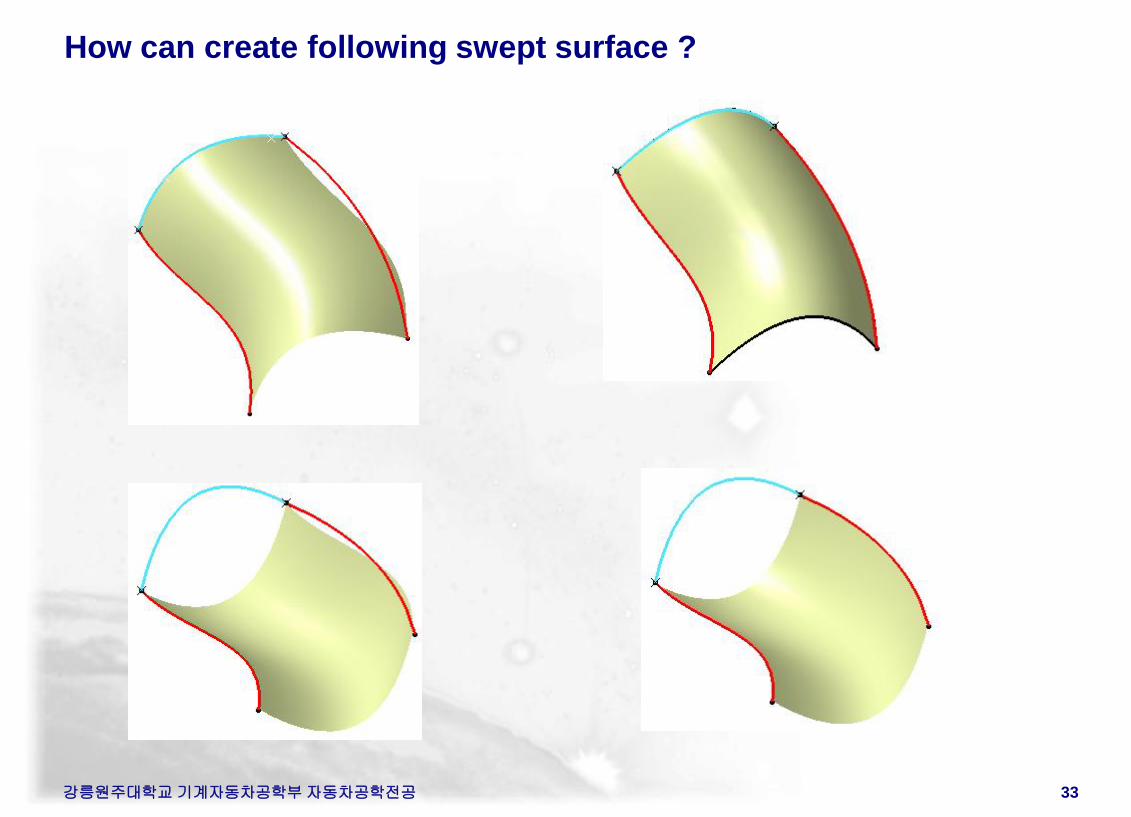
How can create following swept surface ?
강릉원주대학교 기계자동차공학부 자동차공학전공 33
강릉원주대학교 기계자동차공학부 자동차공학전공 34
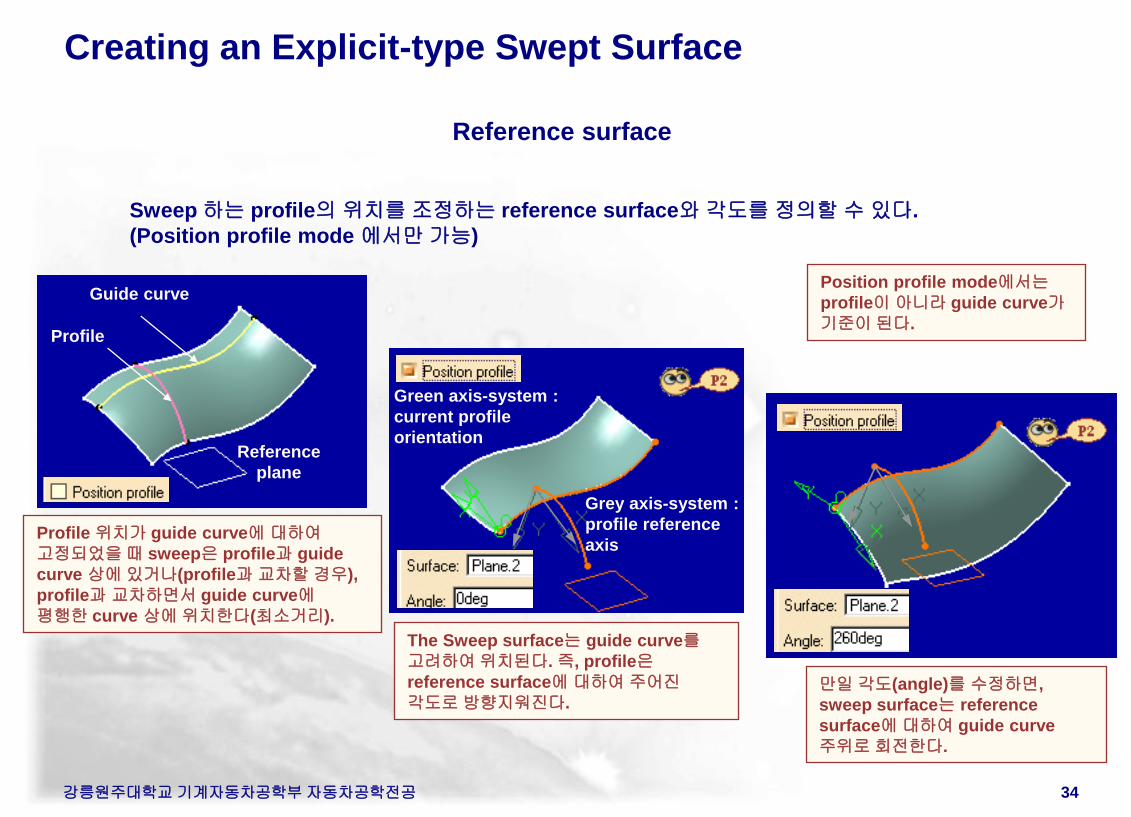
Creating an Explicit-type Swept Surface
Sweep 하는 profile의 위치를 조정하는 reference surface와 각도를 정의할 수 있다.
(Position profile mode 에서만 가능)
Reference
plane
Guide curve
Profile
The Sweep surface는 guide curve를
고려하여 위치된다. 즉, profile은
reference surface에 대하여 주어진
각도로 방향지워진다.
Profile 위치가 guide curve에 대하여
고정되었을 때 sweep은 profile과 guide
curve 상에 있거나(profile과 교차할 경우),
profile과 교차하면서 guide curve에
평행한 curve 상에 위치한다(최소거리).
Green axis-system :
current profile
orientation
Grey axis-system :
profile reference
axis
만일 각도(angle)를 수정하면,
sweep surface는 reference
surface에 대하여 guide curve
주위로 회전한다.
Reference surface
Position profile mode에서는
profile이 아니라 guide curve가
기준이 된다.
강릉원주대학교 기계자동차공학부 자동차공학전공 35
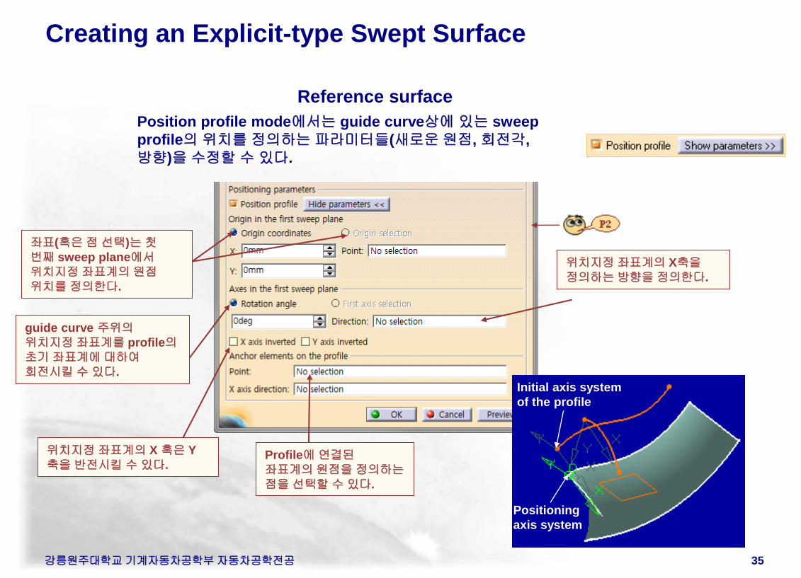
Creating an Explicit-type Swept Surface
Reference surface
Position profile mode에서는 guide curve상에 있는 sweep
profile의 위치를 정의하는 파라미터들(새로운 원점, 회전각,
방향)을 수정할 수 있다.
좌표(혹은 점 선택)는 첫
번째 sweep plane에서
위치지정 좌표계의 원점
위치를 정의한다.
guide curve 주위의
위치지정 좌표계를 profile의
초기 좌표계에 대하여
회전시킬 수 있다.
위치지정 좌표계의 X 혹은 Y
축을 반전시킬 수 있다. Profile에 연결된
좌표계의 원점을 정의하는
점을 선택할 수 있다.
위치지정 좌표계의 X축을
정의하는 방향을 정의한다.
Initial axis system
of the profile
Positioning
axis system
강릉원주대학교 기계자동차공학부 자동차공학전공 36
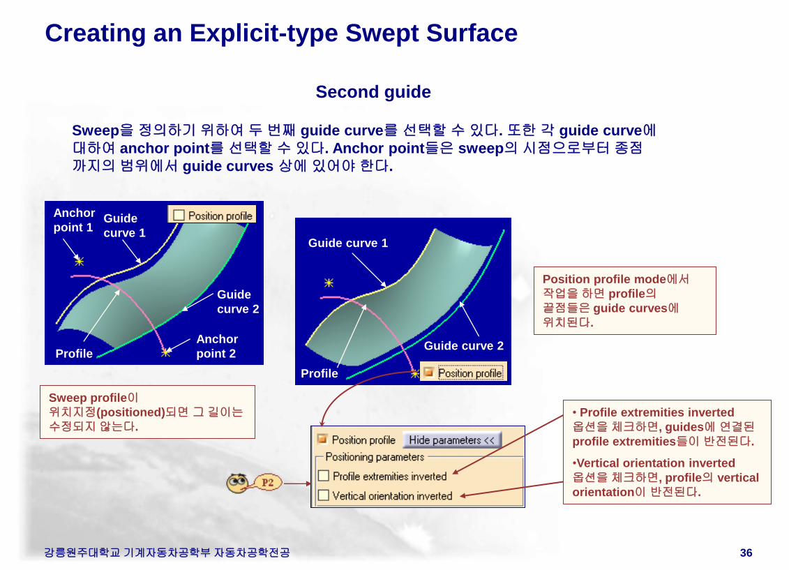
Creating an Explicit-type Swept Surface
Guide
curve 1
Guide
curve 2
Profile
Anchor
point 2
Anchor
point 1
Sweep을 정의하기 위하여 두 번째 guide curve를 선택할 수 있다. 또한 각 guide curve에
대하여 anchor point를 선택할 수 있다. Anchor point들은 sweep의 시점으로부터 종점
까지의 범위에서 guide curves 상에 있어야 한다.
Second guide
Sweep profile이
위치지정(positioned)되면 그 길이는
수정되지 않는다.
Position profile mode에서
작업을 하면 profile의
끝점들은 guide curves에
위치된다.
Guide curve 1
Guide curve 2
Profile
• Profile extremities inverted
옵션을 체크하면, guides에 연결된
profile extremities들이 반전된다.
•Vertical orientation inverted
옵션을 체크하면, profile의 vertical
orientation이 반전된다.
강릉원주대학교 기계자동차공학부 자동차공학전공 37
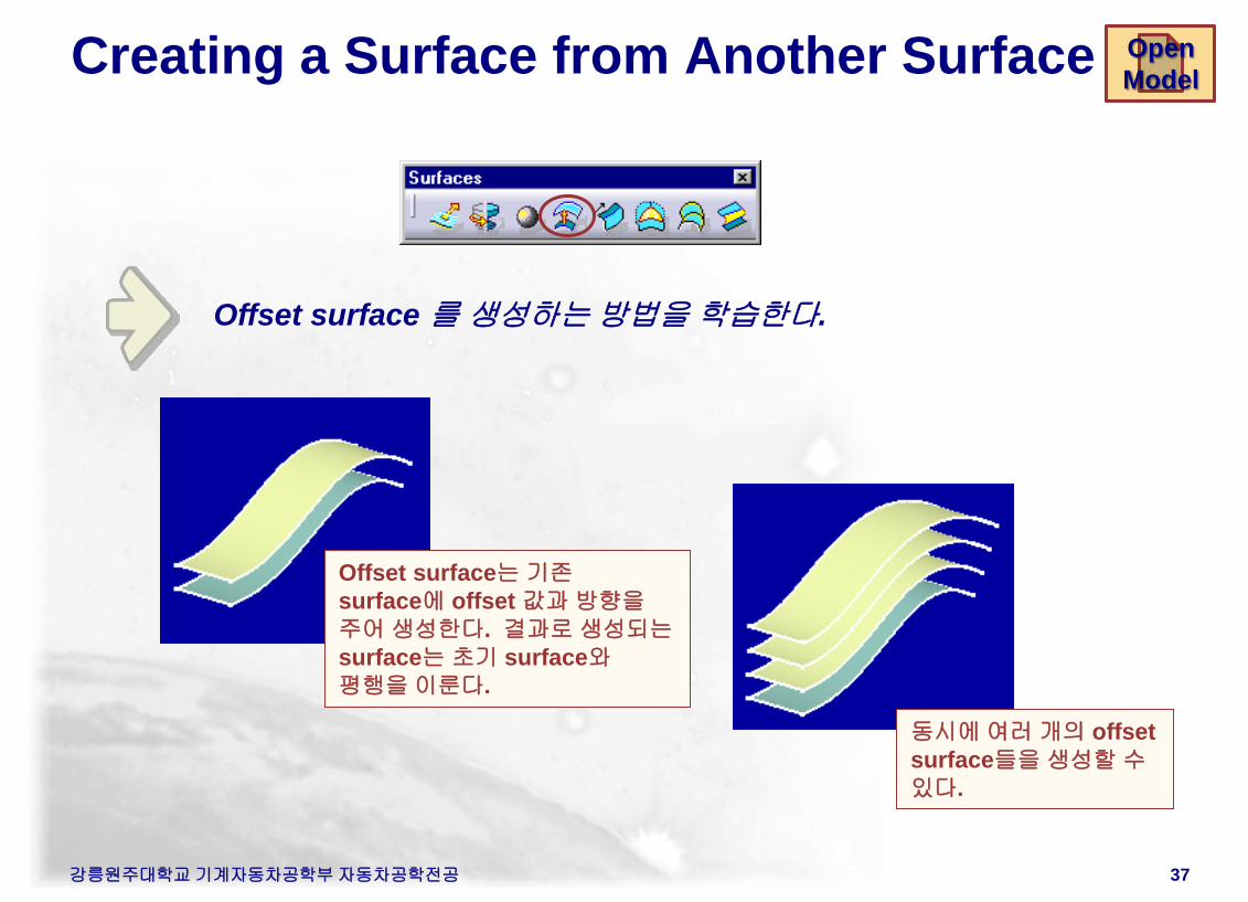
Creating a Surface from Another Surface
Offset surface 를 생성하는 방법을 학습한다.
동시에 여러 개의 offset
surface들을 생성할 수
있다.
Offset surface는 기존
surface에 offset 값과 방향을
주어 생성한다. 결과로 생성되는
surface는 초기 surface와
평행을 이룬다.
Open
Model
강릉원주대학교 기계자동차공학부 자동차공학전공 38
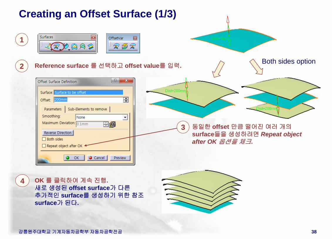
Creating an Offset Surface (1/3)
1
2 Reference surface 를 선택하고 offset value를 입력.
OK 를 클릭하여 계속 진행.
새로 생성된 offset surface가 다른
추가적인 surface를 생성하기 위한 참조
surface가 된다.
동일한 offset 만큼 떨어진 여러 개의
surface들을 생성하려면 Repeat object
after OK 옵션을 체크.
3
4
Both sides option
강릉원주대학교 기계자동차공학부 자동차공학전공 39
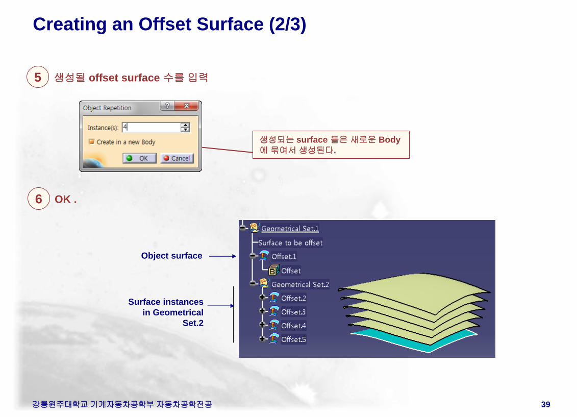
Creating an Offset Surface (2/3)
5 생성될 offset surface 수를 입력
6 OK .
Object surface
Surface instances
in Geometrical
Set.2
생성되는 surface 들은 새로운 Body
에 묶여서 생성된다.
강릉원주대학교 기계자동차공학부 자동차공학전공 40
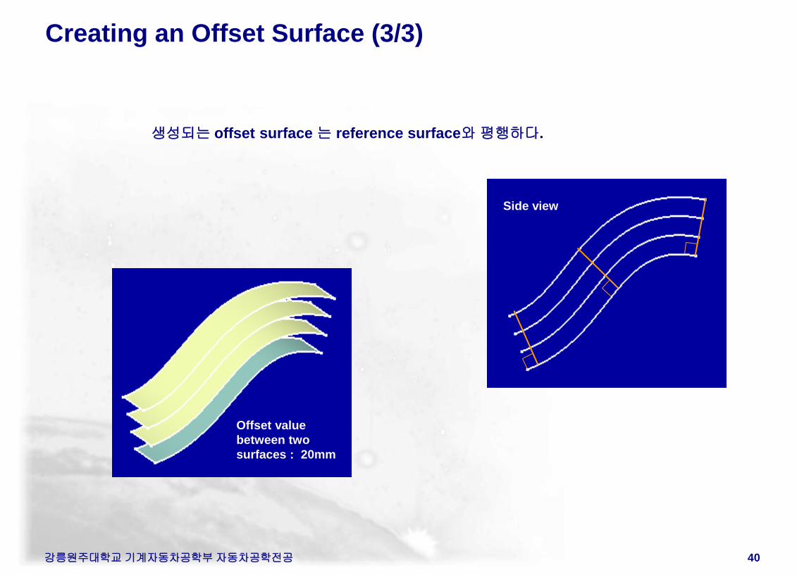
Creating an Offset Surface (3/3)
생성되는 offset surface 는 reference surface와 평행하다.
Offset value
between two
surfaces : 20mm
Side view
강릉원주대학교 기계자동차공학부 자동차공학전공 41
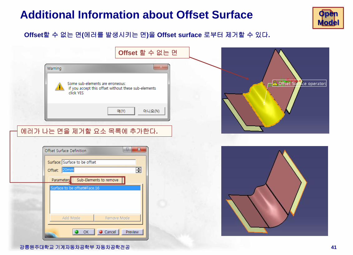
Additional Information about Offset Surface
Offset할 수 없는 면(에러를 발생시키는 면)을 Offset surface 로부터 제거할 수 있다.
Offset 할 수 없는 면
에러가 나는 면을 제거할 요소 목록에 추가한다.
Open
Model
강릉원주대학교 기계자동차공학부 자동차공학전공 42
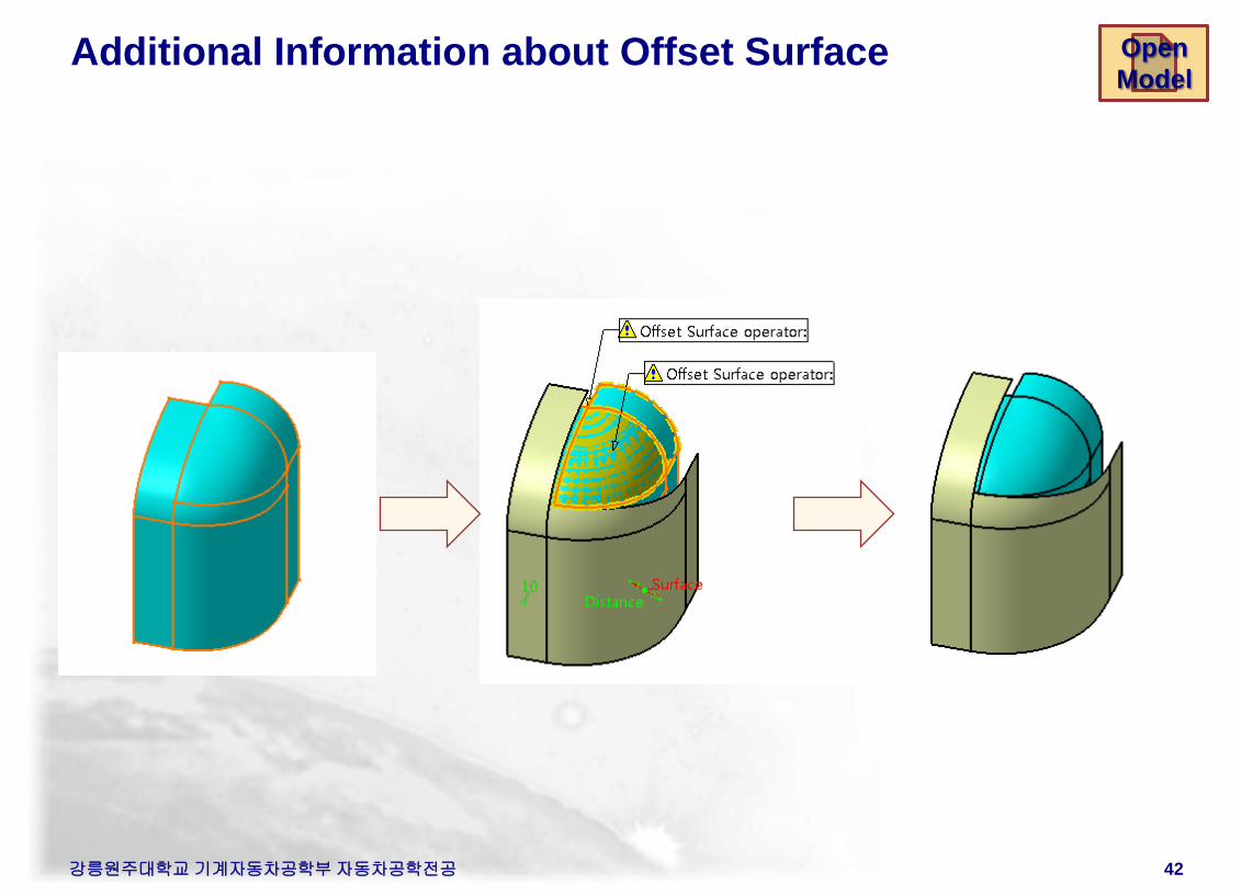
Additional Information about Offset Surface Open
Model
강릉원주대학교 기계자동차공학부 자동차공학전공 43
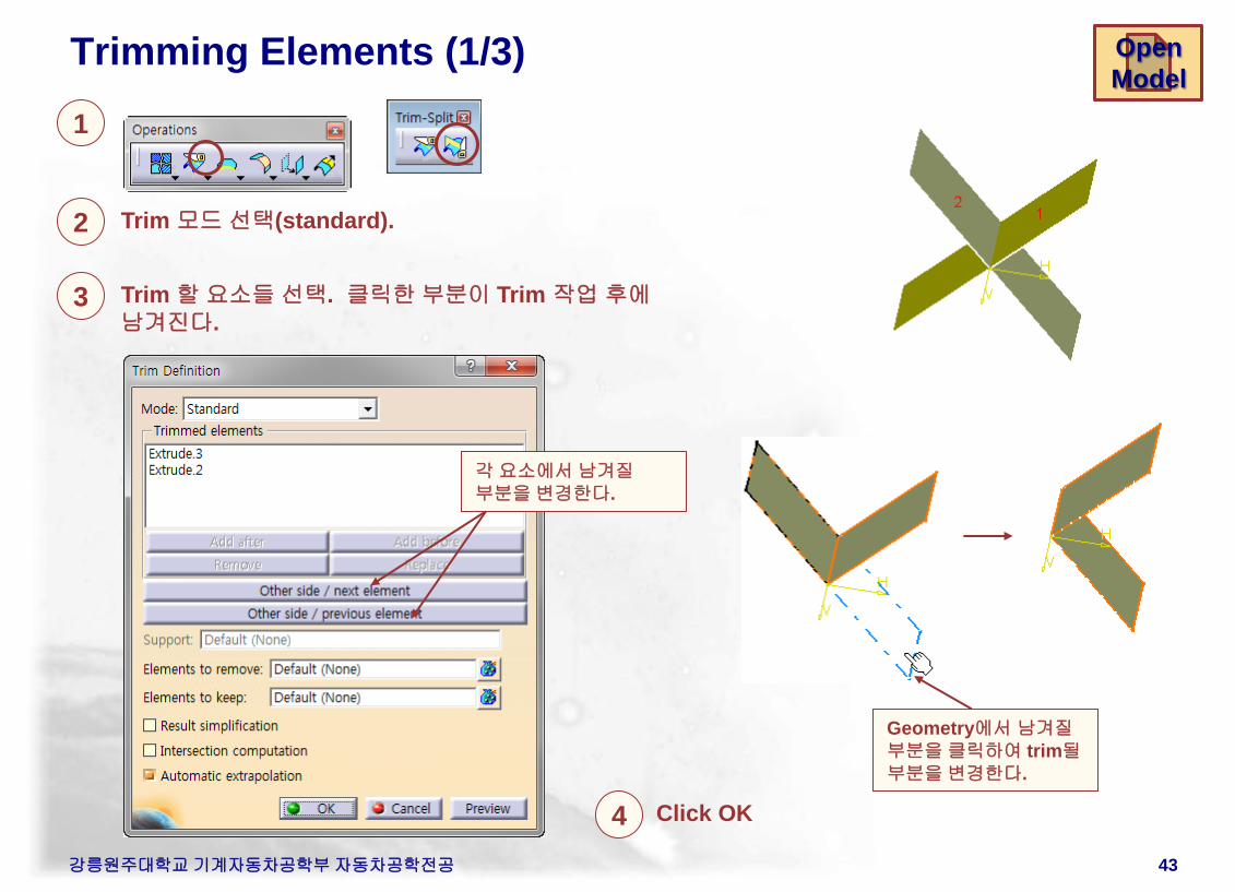
Trimming Elements (1/3)
1
2 Trim 모드 선택(standard).
4 Click OK
각 요소에서 남겨질
부분을 변경한다.
Open
Model
3 Trim 할 요소들 선택. 클릭한 부분이 Trim 작업 후에
남겨진다.
Geometry에서 남겨질
부분을 클릭하여 trim될
부분을 변경한다.
강릉원주대학교 기계자동차공학부 자동차공학전공 44
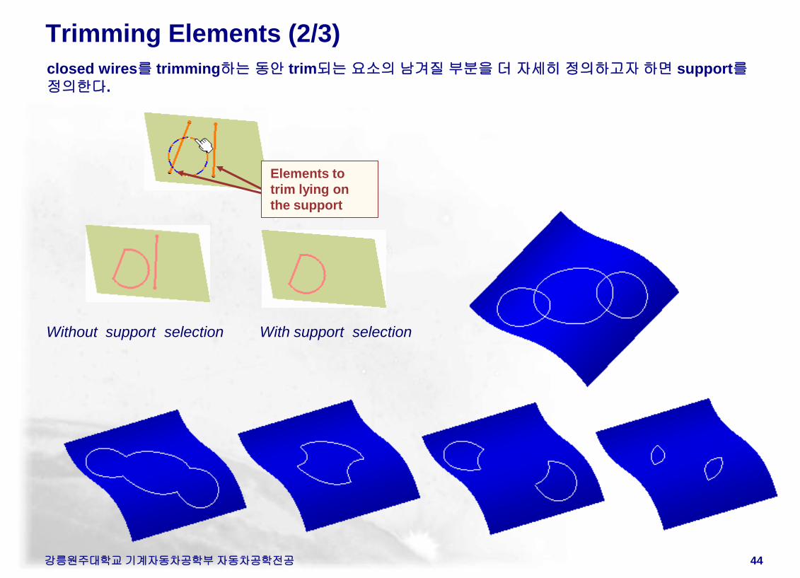
Trimming Elements (2/3)
closed wires를 trimming하는 동안 trim되는 요소의 남겨질 부분을 더 자세히 정의하고자 하면 support를
정의한다.
Elements to
trim lying on
the support
Without support selection With support selection
강릉원주대학교 기계자동차공학부 자동차공학전공 45
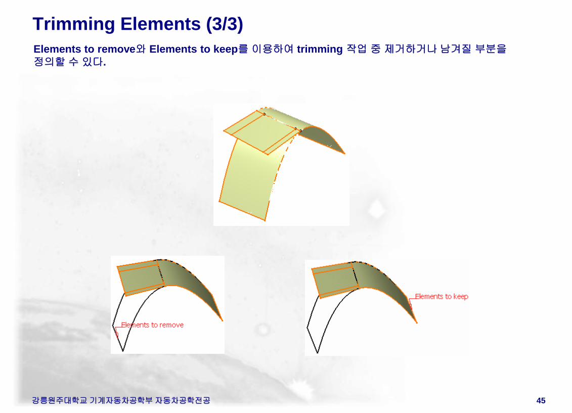
Trimming Elements (3/3)
Elements to remove와 Elements to keep를 이용하여 trimming 작업 중 제거하거나 남겨질 부분을
정의할 수 있다.
강릉원주대학교 기계자동차공학부 자동차공학전공 46
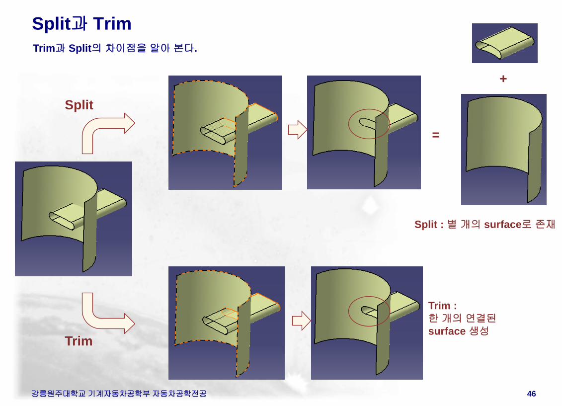
Split과 Trim
Trim과 Split의 차이점을 알아 본다.
Split
Trim
=
+
Trim :
한 개의 연결된
surface 생성
Split : 별 개의 surface로 존재
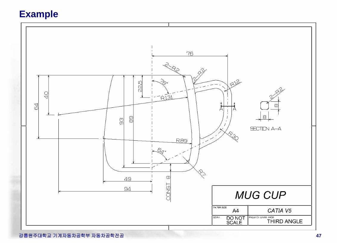
Example
강릉원주대학교 기계자동차공학부 자동차공학전공 47
강릉원주대학교 기계자동차공학부 자동차공학전공 48
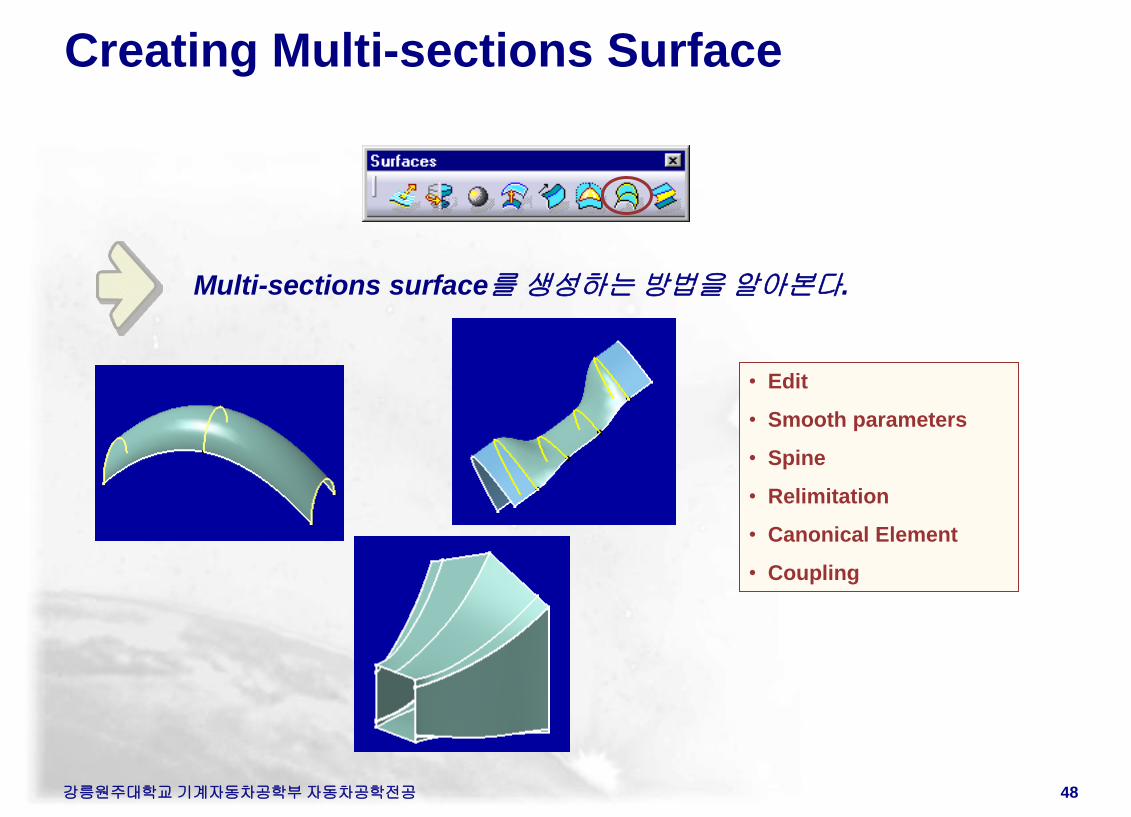
Creating Multi-sections Surface
Multi-sections surface를 생성하는 방법을 알아본다.
• Edit
• Smooth parameters
• Spine
• Relimitation
• Canonical Element
• Coupling
강릉원주대학교 기계자동차공학부 자동차공학전공 49
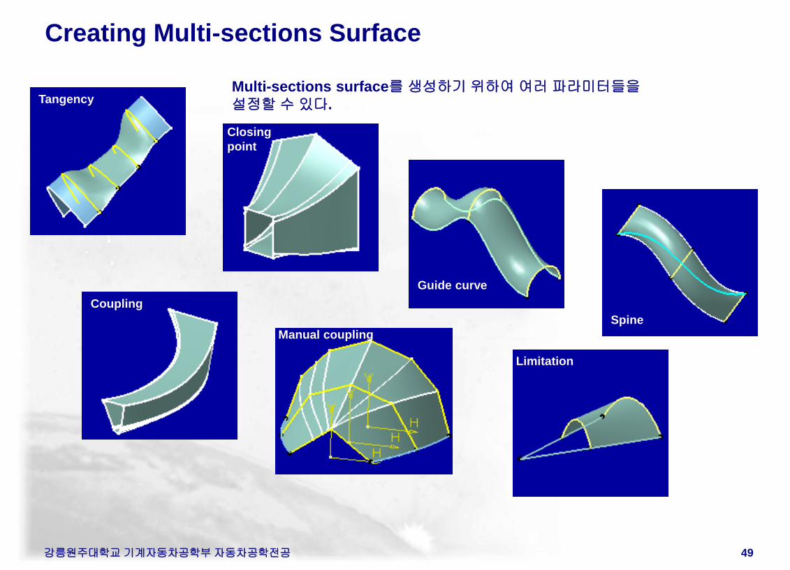
Creating Multi-sections Surface
Multi-sections surface를 생성하기 위하여 여러 파라미터들을
설정할 수 있다. Tangency
Guide curve
Closing
point
Spine
Coupling
Limitation
Manual coupling
Creating Multi-sections Surface
강릉원주대학교 기계자동차공학부 자동차공학전공 50
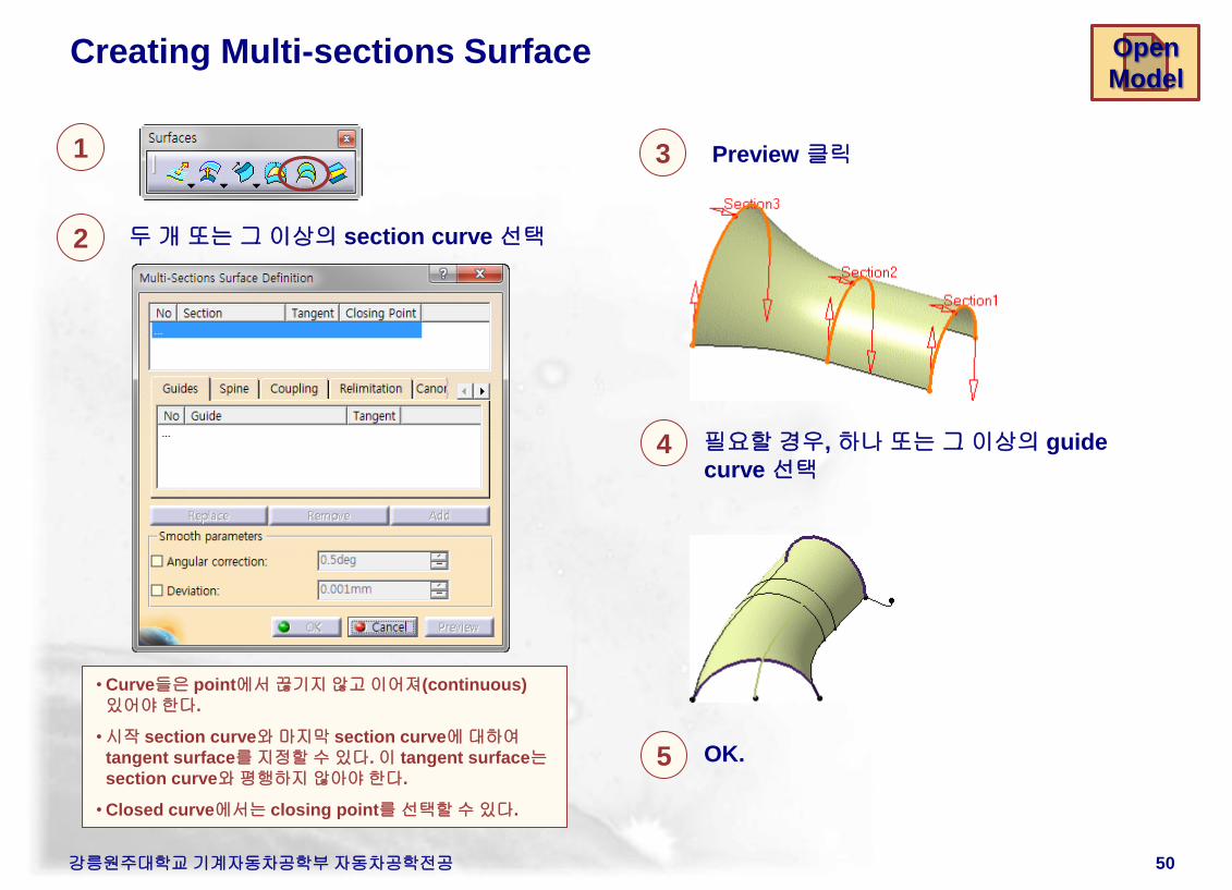
1
2 두 개 또는 그 이상의 section curve 선택
필요할 경우, 하나 또는 그 이상의 guide
curve 선택
3
• Curve들은 point에서 끊기지 않고 이어져(continuous)
있어야 한다.
•시작 section curve와 마지막 section curve에 대하여
tangent surface를 지정할 수 있다. 이 tangent surface는
section curve와 평행하지 않아야 한다.
• Closed curve에서는 closing point를 선택할 수 있다.
Preview 클릭
Open
Model
4
OK. 5
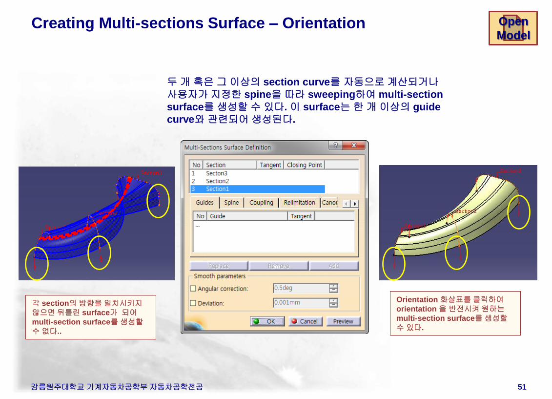
Creating Multi-sections Surface – Orientation
강릉원주대학교 기계자동차공학부 자동차공학전공 51
각 section의 방향을 일치시키지
않으면 뒤틀린 surface가 되어
multi-section surface를 생성할
수 없다..
Orientation 화살표를 클릭하여
orientation 을 반전시켜 원하는
multi-section surface를 생성할
수 있다.
두 개 혹은 그 이상의 section curve를 자동으로 계산되거나
사용자가 지정한 spine을 따라 sweeping하여 multi-section
surface를 생성할 수 있다. 이 surface는 한 개 이상의 guide
curve와 관련되어 생성된다.
Open
Model
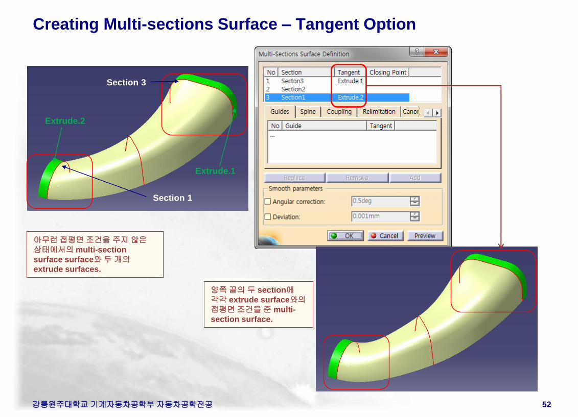
Creating Multi-sections Surface – Tangent Option
강릉원주대학교 기계자동차공학부 자동차공학전공 52
아무런 접평면 조건을 주지 않은
상태에서의 multi-section
surface surface와 두 개의
extrude surfaces.
양쪽 끝의 두 section에
각각 extrude surface와의
접평면 조건을 준 multi-
section surface.
Section 3
Section 1
Extrude.1
Extrude.2
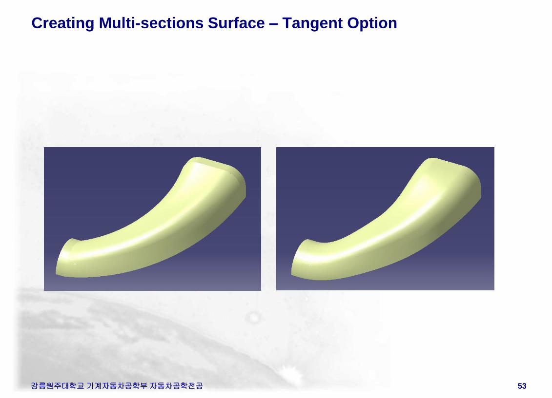
Creating Multi-sections Surface – Tangent Option
강릉원주대학교 기계자동차공학부 자동차공학전공 53
강릉원주대학교 기계자동차공학부 자동차공학전공 54
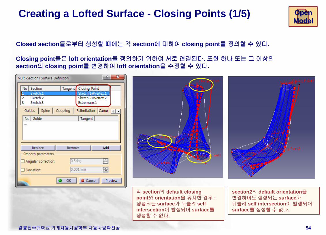
Creating a Lofted Surface - Closing Points (1/5)
각 section의 default closing
point와 orientation을 유지한 경우 :
생성되는 surface가 뒤틀려 self
intersection이 발생되어 surface를
생성할 수 없다.
Closed section들로부터 생성할 때에는 각 section에 대하여 closing point를 정의할 수 있다.
Closing point들은 loft orientation을 정의하기 위하여 서로 연결된다. 또한 하나 또는 그 이상의
section의 closing point를 변경하여 loft orientation을 수정할 수 있다.
Open
Model
section2의 default orientation을
변경하여도 생성되는 surface가
뒤틀려 self intersection이 발생되어
surface를 생성할 수 없다.
강릉원주대학교 기계자동차공학부 자동차공학전공 55
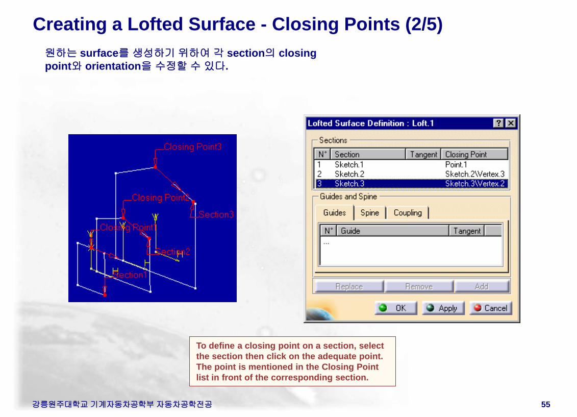
Creating a Lofted Surface - Closing Points (2/5)
원하는 surface를 생성하기 위하여 각 section의 closing
point와 orientation을 수정할 수 있다.
To define a closing point on a section, select
the section then click on the adequate point.
The point is mentioned in the Closing Point
list in front of the corresponding section.
강릉원주대학교 기계자동차공학부 자동차공학전공 56
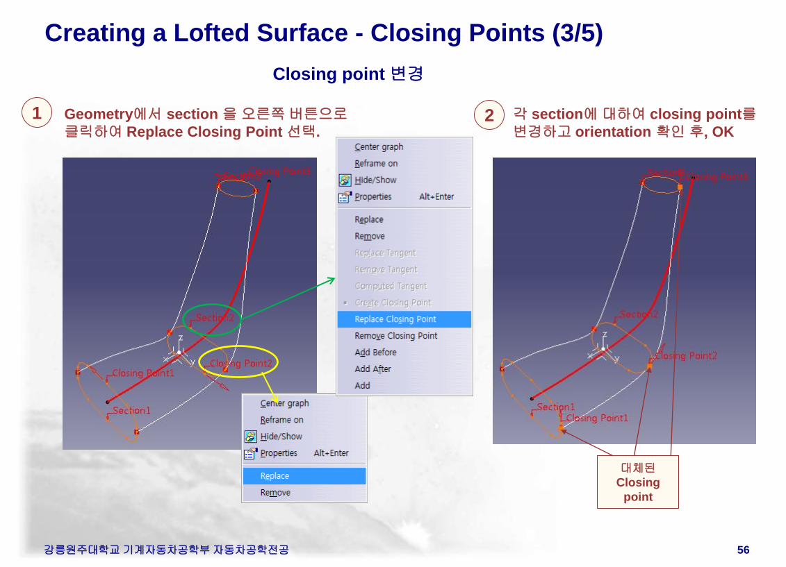
Creating a Lofted Surface - Closing Points (3/5)
Closing point 변경
1 Geometry에서 section 을 오른쪽 버튼으로
클릭하여 Replace Closing Point 선택.
각 section에 대하여 closing point를
변경하고 orientation 확인 후, OK 2
대체된
Closing
point
강릉원주대학교 기계자동차공학부 자동차공학전공 57
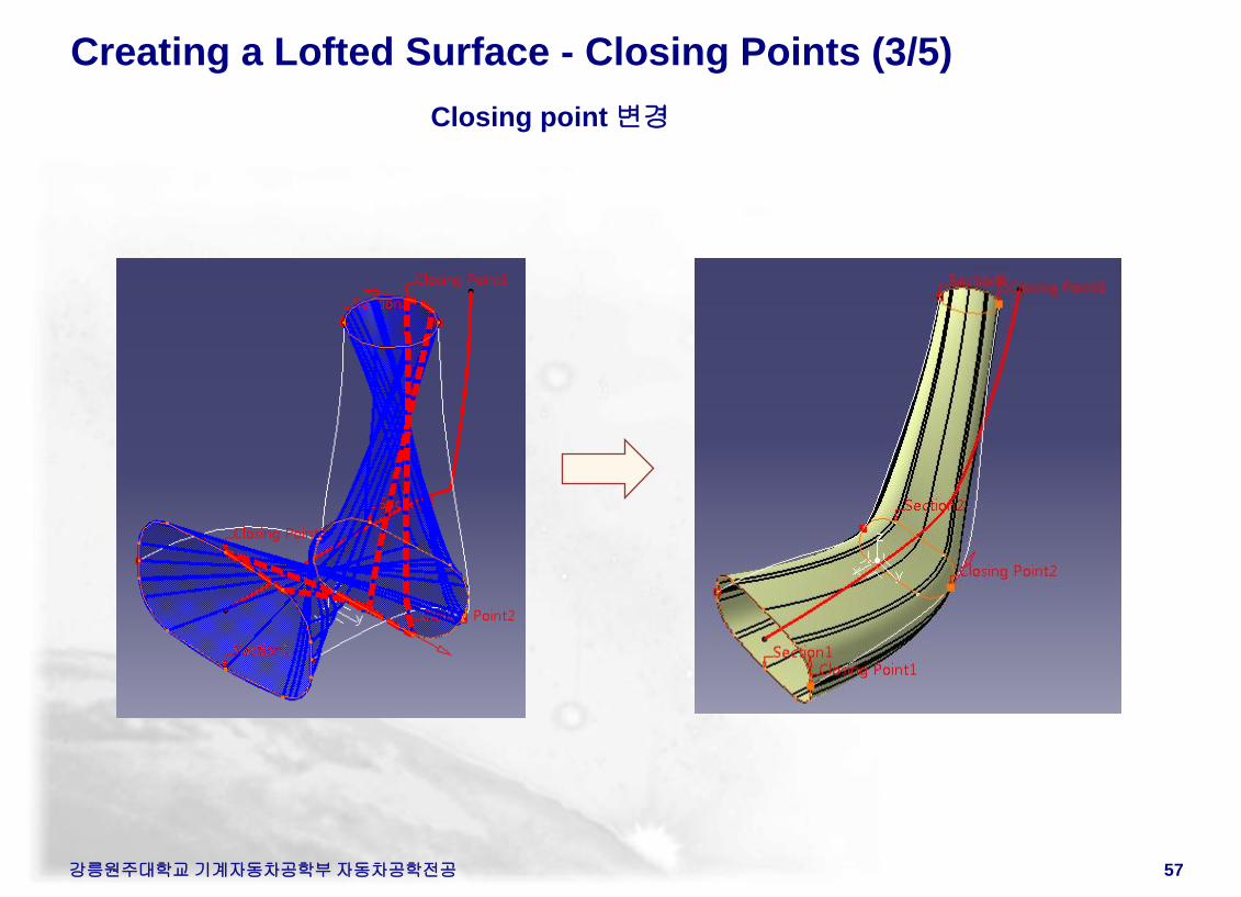
Creating a Lofted Surface - Closing Points (3/5)
Closing point 변경
강릉원주대학교 기계자동차공학부 자동차공학전공 58
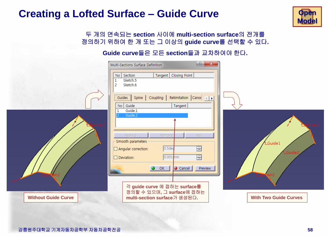
Creating a Lofted Surface – Guide Curve
Guide curve 1
With Two Guide Curves Without Guide Curve
두 개의 연속되는 section 사이에 multi-section surface의 전개를
정의하기 위하여 한 개 또는 그 이상의 guide curve를 선택할 수 있다.
Guide curve들은 모든 section들과 교차하여야 한다.
Section 1
Section 2
각 guide curve 에 접하는 surface를
정의할 수 있으며, 그 surface에 접하는
multi-section surface가 생성된다.
Section 3
Guide curve 2
Open
Model
강릉원주대학교 기계자동차공학부 자동차공학전공 59
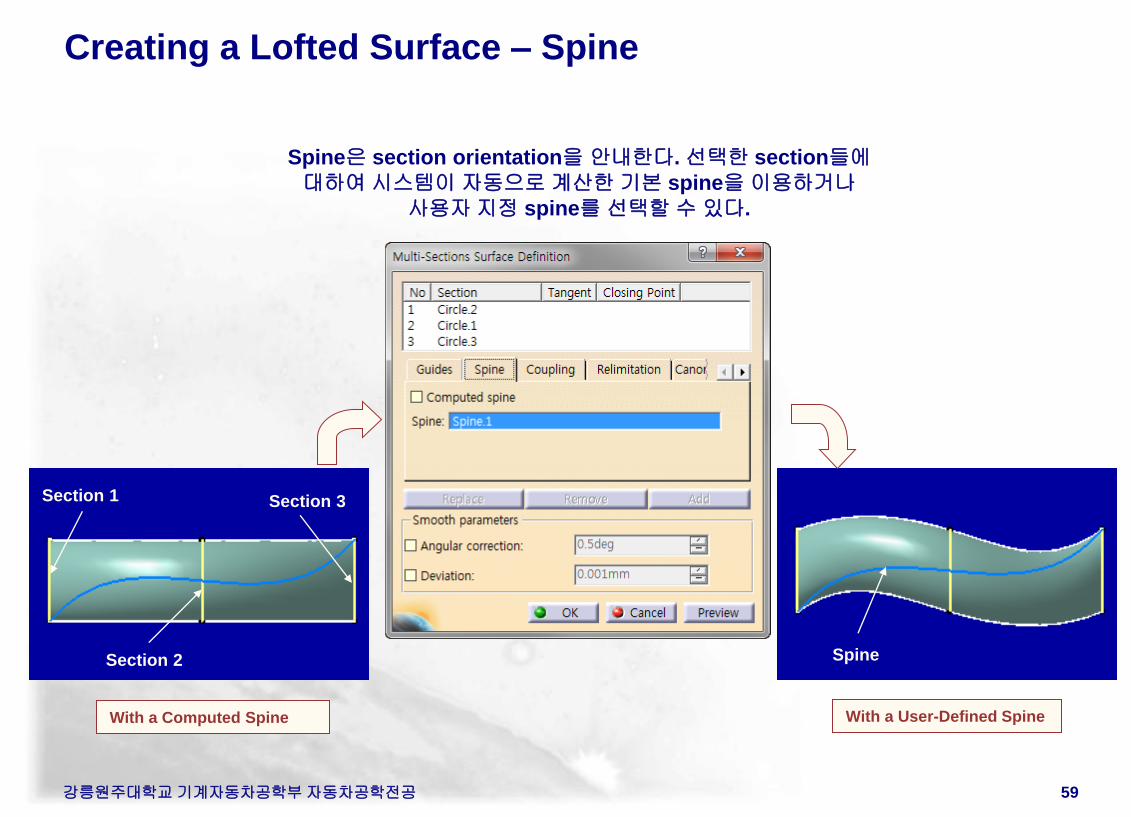
Creating a Lofted Surface – Spine
Section 2 Spine
With a User-Defined Spine With a Computed Spine
Spine은 section orientation을 안내한다. 선택한 section들에
대하여 시스템이 자동으로 계산한 기본 spine을 이용하거나
사용자 지정 spine를 선택할 수 있다.
Section 1 Section 3
강릉원주대학교 기계자동차공학부 자동차공학전공 60
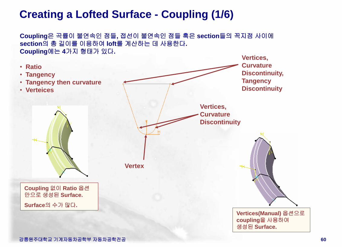
Creating a Lofted Surface - Coupling (1/6)
Coupling은 곡률이 불연속인 점들, 접선이 불연속인 점들 혹은 section들의 꼭지점 사이에
section의 총 길이를 이용하여 loft를 계산하는 데 사용한다.
Coupling에는 4가지 형태가 있다.
• Ratio
• Tangency
• Tangency then curvature
• Verteices
Vertices,
Curvature
Discontinuity,
Tangency
Discontinuity
Vertices,
Curvature
Discontinuity
Vertex
Ratio option
Coupling 없이 Ratio 옵션
만으로 생성된 Surface.
Surface의 수가 많다.
Vertices(Manual) 옵션으로
coupling을 사용하여
생성된 Surface.
Example
강릉원주대학교 기계자동차공학부 자동차공학전공 61
Open
Model
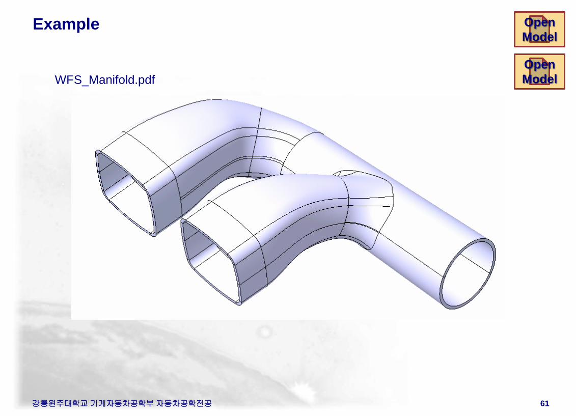
WFS_Manifold.pdf
Open
Model
Example
강릉원주대학교 기계자동차공학부 자동차공학전공 62
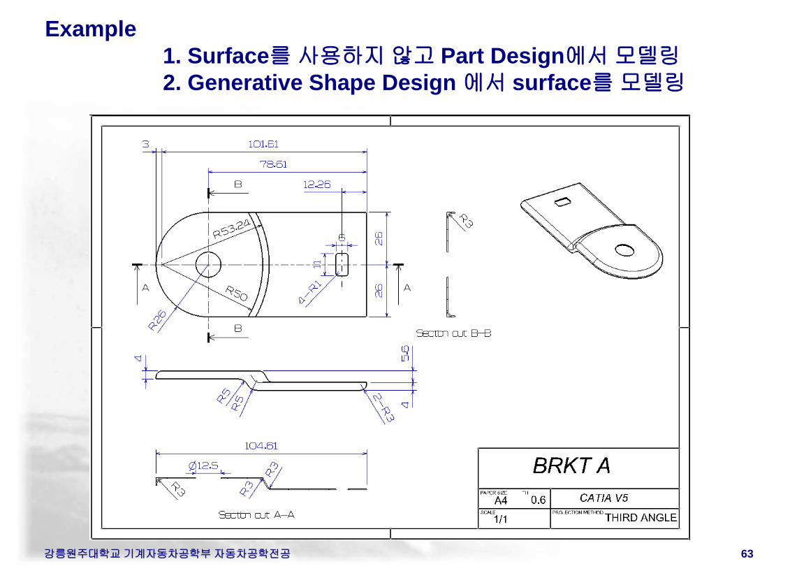
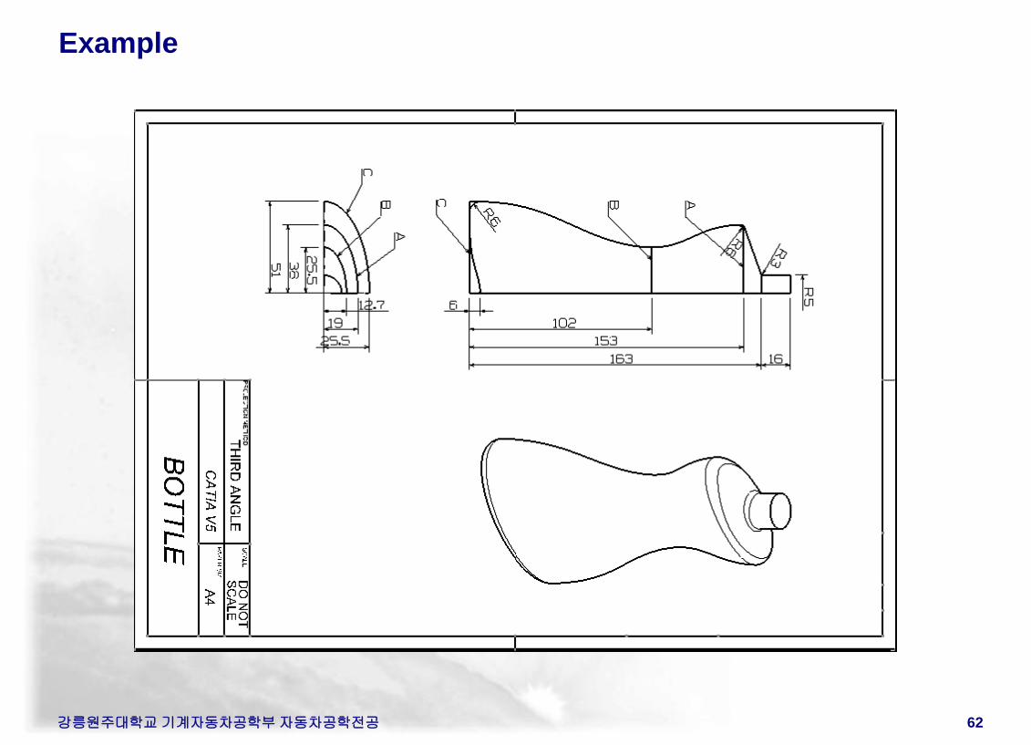
Example
1. Surface를 사용하지 않고 Part Design에서 모델링
2. Generative Shape Design 에서 surface를 모델링
강릉원주대학교 기계자동차공학부 자동차공학전공 63