Embed Size (px)
Citation preview
_____________________________________________________________________________________
Rev.1.01
r e v . 1 . 0 1 145 Rt. 46 West E‐mail: sales@electro‐set.net Wayne, NJ 07470 Web: www.Electro‐Set.net
1
1
CB-055 Bluetooth Module
October 7, 2014
Introduction
This application note will show two minimal code set ups to operate the Bluetooth CB-055, one with an Arduino board and the other with Cardinal’s CB-026 Microchip microcontroller module.
Arduino
The Arduino example will show how to transmit and receive data in SPP mode between the Bluetooth module and a Bluetooth capable PC. We will use a terminal emulator program on the PC to show the characters transmitted from the Bluetooth module and also to send characters. The Arduino code will look for the characters “0” through “8” from the PC and illuminate 0 through 8 LEDs on the IO expander respectively. If it receives an “n” or “N” then it will transmit the string “Hi, call me Blue” back to the PC.
Before proceeding any further, please have the Arduino software installed on to your computer. Visit Arduino’s user setup guide at http://arduino.cc/en/Guide/windows for step-by-step instructions.
Hardware
Parts List:
Arduino Uno USB type B connector CB-I-022 Cardinal Interface Board CB-031 IO module CB-055 Bluetooth module Bluetooth enabled PC
_____________________________________________________________________________________
Rev.1.01
r e v . 1 . 0 1 145 Rt. 46 West E‐mail: sales@electro‐set.net Wayne, NJ 07470 Web: www.Electro‐Set.net
2
2
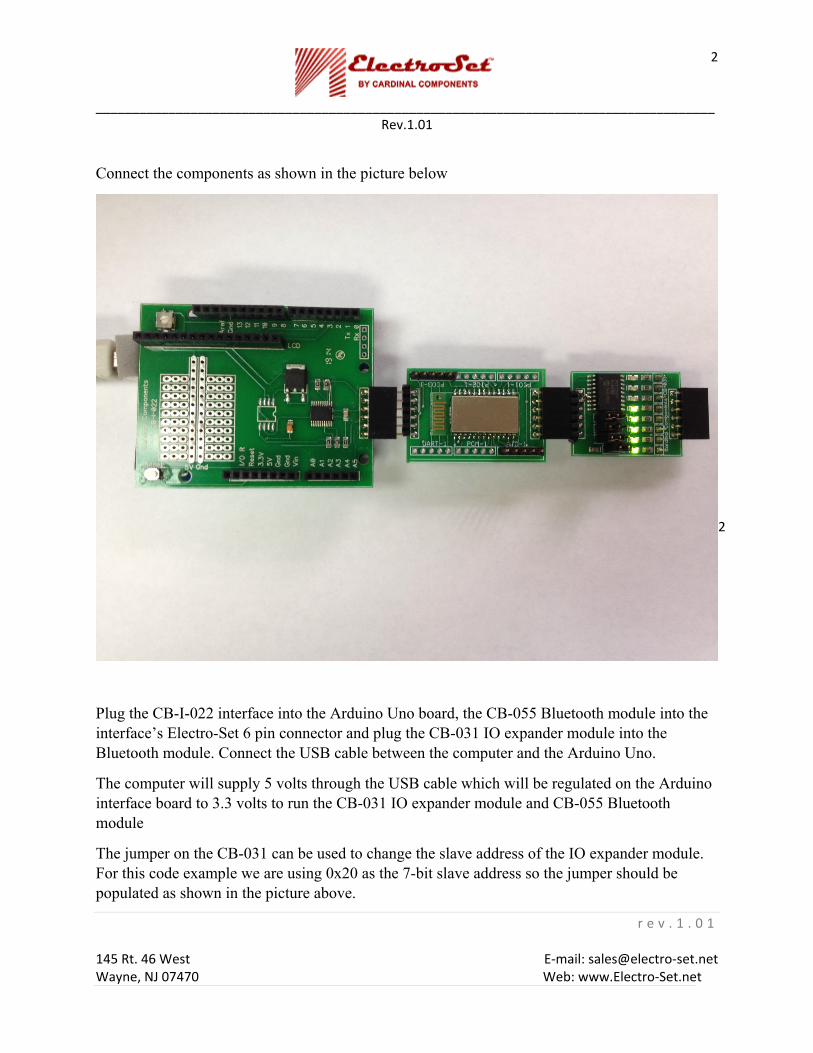
Connect the components as shown in the picture below
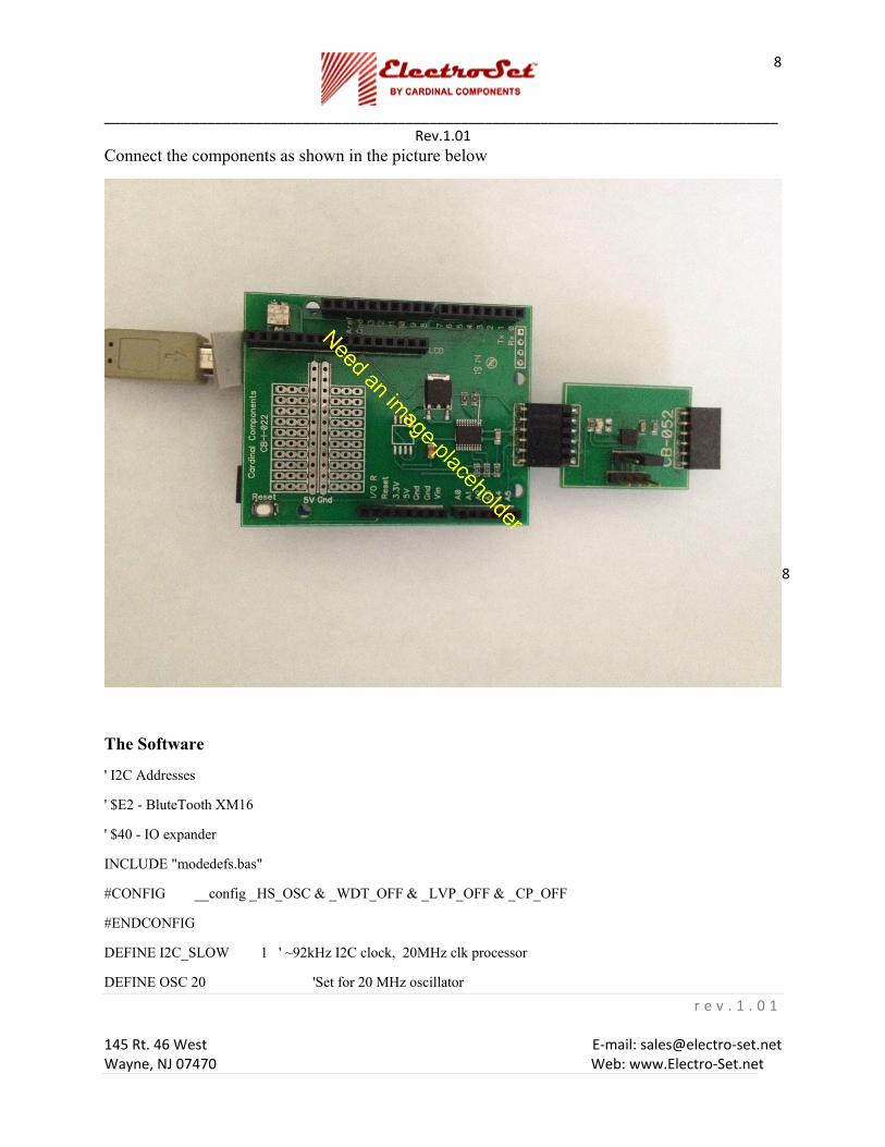
Plug the CB-I-022 interface into the Arduino Uno board, the CB-055 Bluetooth module into the interface’s Electro-Set 6 pin connector and plug the CB-031 IO expander module into the Bluetooth module. Connect the USB cable between the computer and the Arduino Uno.
The computer will supply 5 volts through the USB cable which will be regulated on the Arduino interface board to 3.3 volts to run the CB-031 IO expander module and CB-055 Bluetooth module
The jumper on the CB-031 can be used to change the slave address of the IO expander module. For this code example we are using 0x20 as the 7-bit slave address so the jumper should be populated as shown in the picture above.

_____________________________________________________________________________________
Rev.1.01
r e v . 1 . 0 1 145 Rt. 46 West E‐mail: sales@electro‐set.net Wayne, NJ 07470 Web: www.Electro‐Set.net
3
3
When the Bluetooth module is powered up it should have been discovered by the Bluetooth enabled PC. It will show with the name XM-16. The first time it is discovered the device needs to be paired, the pair code is 1234. On pairing, a virtual COMM port will be created, in practice two COMM ports may be created the lower numbered port is usually the SPP data stream we need. You can use the Windows device manager to show the COMM ports that have been created. We will observe the data arriving at the PC over the Bluetooth SPP protocol by connecting to the COMM port with a terminal emulator such as hyperterm, a program that came with Windows XP or an equivalent terminal emulation program.
The Software
#include <Wire.h> // Wire I2C library
#define BT_ADDRESS 0x71 // 7 bit I2C Bluetooth address
#define IO_ADDRESS 0x20 // 7 bit I2C IO_ADDRESS of I/O expander
byte numReadBtBytes; // number of bytes in BT read FIFO
byte readBtByte; / byte read from BT FIFO
unsigned int pOut=0; // value to write to IO expander
int count=450; // used to control timing of when prompt message sent
int promptLastSent=0; // flag to indicat
void writeBtString(char * s); // write string to Bluetooth FIFO
byte readBtByteFmAddr(byte addr); // read one byte from Bluetooth register address addr
void writeIORegister(byte addr, byte dta); // write one data byte to IO expander register address addr
void setup()
{
Serial.begin(9600); // initialize serial monitor to 9600 baud
Serial.println("Electro-Set"); // welcome message over Arduino serial monitor poer
Serial.println("CB-055 Test"); // welcome message
_____________________________________________________________________________________
Rev.1.01
r e v . 1 . 0 1 145 Rt. 46 West E‐mail: sales@electro‐set.net Wayne, NJ 07470 Web: www.Electro‐Set.net
4
4
Wire.begin(); // initialize I2C port
writeIORegister(0x00,0x00); // set all 8 IO expander lines as output
writeBtString("\n\n\rElectro-Set\n\rCB-055 Test\n\r"); // BT welcome message, seen on PC terminal
}
void loop()
{
numReadBtBytes = readBtByteFmAddr(0x01); // read reg 0x01, the number of bytes present in the receive FIFO
if (numReadBtBytes>0){
readBtByte = readBtByteFmAddr(0x03); // Get one byte from the receive FIFO
if ((readBtByte >= '0') && (readBtByte <= '8')){ // check to see if either 'p' or 'P'
pOut=1<<(readBtByte-'0'); // if a 'p' set the pDet flag
pOut-=1;
writeIORegister(0x0a,pOut);
count=0; // reset loop counter
promptLastSent=0;
}
if ((readBtByte =='n') || (readBtByte == 'N')){ // check to see if either 'p' or 'P'
writeBtString("\n\rHi, call me Blue"); // prompt message bytes to send over Bluetooth
count=0; // reset loop counter
promptLastSent=0;
}
}
if(++count>500){ // after 500 loops
count=0; // reset loop counter
if(promptLastSent==0){ // prevents consecutive outputs of the prompt
writeBtString("\n\rTry typing 0 thro 8 or an 'n'\n\r"); // prompt message bytes to send over Bluetooth
promptLastSent=1; // set flag that prompt was last (just) sent
_____________________________________________________________________________________
Rev.1.01
r e v . 1 . 0 1 145 Rt. 46 West E‐mail: sales@electro‐set.net Wayne, NJ 07470 Web: www.Electro‐Set.net
5
5
}
}
delay(10);
} // end of loop()
void writeIORegister(byte addr, byte dta){ // function to write IO expander module
Wire.beginTransmission(IO_ADDRESS); // start of I2C transmission to IO
Wire.write(addr); // internal register address
Wire.write(dta); // data byte to write to register
Wire.endTransmission(); // Complete the I2C transmission
}
void writeBtString(char * s){ // function to write string to BT Tx FIFO
Wire.beginTransmission(BT_ADDRESS); // start of I2C transmission to Bluetooth
Wire.write(0x03); // internal register address of FIFO
Wire.write(s); // string to send over Bluetooth
Wire.endTransmission(); // Complete the I2C transmission
}
byte readBtByteFmAddr(byte addr){ // function to read byte from BT Rx FIFO
Wire.beginTransmission(BT_ADDRESS); // start of I2C transmission to Bluetooth
Wire.write(addr); // internal address
Wire.endTransmission(); // Complete the I2C write transmission
Wire.requestFrom(BT_ADDRESS, 1); // Read 1 byte into Wire input buffer
while(Wire.available() != 1); // wait for byte
return(Wire.read()); // Get byte from wire buffer
}
Code Operation
_____________________________________________________________________________________
Rev.1.01
r e v . 1 . 0 1 145 Rt. 46 West E‐mail: sales@electro‐set.net Wayne, NJ 07470 Web: www.Electro‐Set.net
6
6
The IO expander module has a 7-bit I2C slave address as 0x20 and the Bluetooth module has a slave address of 0x71 which we also make a #define.
The setup() function is called when sketch starts. The setup code, initializes the Arduino serial monitor baud rate at 9600, outputs a welcome message and then initializes the I2C port as a master. Next we initialize the IO expander to have all 8 lines as output by writing 0x00 to the IODIR register 0x00. Finally in Setup we output a welcome message to the PC via the Bluetooth module with the code line:
writeBtString("\n\n\rElectro-Set\n\rCB-055 Test\n\r"); // BT welcome message, seen on PC terminal
This function uses the Bluetooth module’s internal register address 0x03 which is the transmit/receive FIFO. To transmit data we write to 0x03 as shown in the function definition below.
void writeBtString(char * s){ // function to write string to BT Tx FIFO
Wire.beginTransmission(BT_ADDRESS); // start of I2C transmission to Bluetooth
Wire.write(0x03); // internal register address of FIFO
Wire.write(s); // string to send over Bluetooth
Wire.endTransmission(); // Complete the I2C transmission
}
After setup has completed, sketch causes the function loop() to be repeatedly called.
First we check to see if a byte has been received from the PC. We read the Bluetooth internal register 0x01 which is the count of the bytes in the receive FIFO. The following function reads the number of bytes waiting in the Rx FIFO and puts the value in numReadBtBytes.
numReadBtBytes = readBtByteFmAddr(0x01); // read reg 0x01, the number of bytes present
If ‘numReadBtBytes’ is greater than zero we have received data from the PC and we use the same function but with internal register 0x03 to retrieve one byte from the FIFO.
readBtByte = readBtByteFmAddr(0x03); // Get one byte from the receive FIFO
We check this to see if the byte is between ASCII ‘0’ and ‘8’, if it is we turn on that number of the LEDs on the IO expander module using the following code:
if ((readBtByte >= '0') && (readBtByte <= '8')){ // check to see if either 'p' or 'P'
pOut=1<<(readBtByte-'0'); // if a 'p' set the pDet flag
pOut-=1;
_____________________________________________________________________________________
Rev.1.01
r e v . 1 . 0 1 145 Rt. 46 West E‐mail: sales@electro‐set.net Wayne, NJ 07470 Web: www.Electro‐Set.net
7
7
writeIORegister(0x0a,pOut);
Next we check if the received byte is an ASCII ‘n’ or ‘N’, if it is we send a reply message
if ((readBtByte =='n') || (readBtByte == 'N')){ // check to see if either 'p' or 'P'
writeBtString("\n\rHi, call me Blue"); // prompt message bytes to send over Bluetooth
The bi-directional byte transport has now been shown.
Microchip Module CB-026
The CB-026 example in PICBASIC PRO will read the digital acceleration values from each of the 3 axes and display the data through the serial port.
The CB-026 example in PICBASIC PRO will show how to transmit and receive data in SPP mode between the Bluetooth module and a Bluetooth capable PC. We will use a terminal emulator program on the PC to show the characters transmitted from the Bluetooth module and also to send characters. The CB-026 code will look for the characters “0” through “8” from the PC and illuminate 0 through 8 LEDs on the IO expander respectively. If it receives an “n” or “N” then it will transmit the string “Hi, Call me Blue” back to the PC.
Before proceeding any further, please have the MicroCode Studio PICBASIC PRO suite installed on your computer.
Hardware
Parts List:
Electro-Set module CB-026 microcontroller USB type mini connector CB-055 Bluetooth module CB-031 IO expander module Bluetooth enabled PC with terminal emulator
_____________________________________________________________________________________
Rev.1.01
r e v . 1 . 0 1 145 Rt. 46 West E‐mail: sales@electro‐set.net Wayne, NJ 07470 Web: www.Electro‐Set.net
8
8
Connect the components as shown in the picture below
The Software
' I2C Addresses
' $E2 - BluteTooth XM16
' $40 - IO expander
INCLUDE "modedefs.bas"
#CONFIG __config _HS_OSC & _WDT_OFF & _LVP_OFF & _CP_OFF
#ENDCONFIG
DEFINE I2C_SLOW 1 ' ~92kHz I2C clock, 20MHz clk processor
DEFINE OSC 20 'Set for 20 MHz oscillator
_____________________________________________________________________________________
Rev.1.01
r e v . 1 . 0 1 145 Rt. 46 West E‐mail: sales@electro‐set.net Wayne, NJ 07470 Web: www.Electro‐Set.net
9
9
SCL var PORTC.3 ' Set I2C pins
SDA var PORTC.4
Soutpin var PORTC.6 ' Set serial port pins
Sinpin var PORTC.7
Baud var WORD ' for serial port baud rate
rxNumBytes var word ' bytes received by BT module
pOut var word ' IO expander output word
oneByte var byte
Baud=6 ' serial port 38400 non inverted
pause 10
serout2 soutpin,baud,["Electro-Set",13,10] ' Welecom message on serial port
serout2 soutpin,baud,["CB-055 Test",13,10]
i2cwrite sda,scl,$40,$00,[$00],NoData ' All 8 lines are output
i2cwrite sda,scl,$40,$0a,[$55],NoData ' Set test pattern
' BT has 3 registers
' 1 FIFO space available for transmit bytes
' 2 Number of receive bytes in FIFO
' 3 Data Port (FIFO)
CheckBT:
pause 2000 ' BT module pairing/initialization time
pause 2000
pause 2000
i2cwrite sda,scl,$E2,$03,["Hello",13,10],NoData 'Send welcome string to BT module
pause 2000
loopit:
i2cread SDA,SCL,$E2,$01,[rxNumBytes.byte0,rxNumBytes.byte1],NoData ' number of bytes received by BT
_____________________________________________________________________________________
Rev.1.01
r e v . 1 . 0 1 145 Rt. 46 West E‐mail: sales@electro‐set.net Wayne, NJ 07470 Web: www.Electro‐Set.net
10
10
if rxNumBytes>0 then ‘ if we have anything, get it a byte from the BT module
i2cread SDA,SCL,$E2,$03,[oneByte],nodata ' read a byte from BT into variable
if oneByte>=48 and oneByte<=56 then ' 48 is '0', 56 is '8'
oneByte=oneByte-48 ' 48 is '0'
pOut=$01<<(oneByte)
pOut=pOut-1 ' turn on zero through 8 LEDs
i2cwrite sda,scl,$40,$0a,[pOut.byte0],NoData' set the LEDs
endif
if oneByte=110 or oneByte=78 then ' 110 is 'n', 78 is 'N'
i2cwrite sda,scl,$E2,$03,["Hi, Call me Blue",13,10],NoData ' Msg to BT module
endif
endif
goto loopit
NoData: ' I2C communication failure trap
pause 50
Serout2 soutpin,baud,["Error",13,10]
goto loopit
Code Operation
The line
#CONFIG __config _HS_OSC & _WDT_OFF & _LVP_OFF & _CP_OFF
includes configuration for the programmer in the output hex file so it does not necessary to manually change the entries in the programmer configuration window every time you come to write a new version of your program to the microcontroller.
The port pins for the I2C interface are set on PORTC pins 3 and 4. The CB-026 board wires these to the Electro-Set 6 pin connector.
The microcontroller serial port pins are set on PORTC pins 6 and 7, these connect to the FTDI chip on the CB-026 which couples through to the USB and so when plugged into a PC producing
_____________________________________________________________________________________
Rev.1.01
r e v . 1 . 0 1 145 Rt. 46 West E‐mail: sales@electro‐set.net Wayne, NJ 07470 Web: www.Electro‐Set.net
11
11
a virtual COMM port where the microcontroller’s serial data can be seen on a terminal emulator such as hyperterminal. The terminal emulator should be set to connect to the virtual COMM port assigned to the FTDI driver and connect at 38400,8,N,1.
We declare the variable baud1 for use in the serout2 to set the baud rate. For a baud rate of 38400, baud1 is set to 6, see the MicroChip documentation for other rates and options.
The first parameters for the PicBasicPro functions i2cread and i2cwrite uses and 8-bit slave address which is a one bit left shift of the 7-bit slave address, so the Bluetooth module’s 8-bit slave address is 0xE2 and the IO expander is 0x40.
The Bluetooth module CB-055 I2C interface should be at 100kHz or less so for the 20MHz CB-026 we need to add the line
DEFINE I2C_SLOW 1 ' ~92kHz I2C clock, 20MHz clk processor
We set up the I2C and serial port lines, output a welcome message on the serial port and initialize the IO expander to have all 8 lines as output.
The Bluetooth module operates in SPP protocol which provides for bi-directional byte data transport. Three internal register addresses are used for this transport:
' BT has 3 registers
' 0x01 FIFO space available for transmit bytes, size word
' 0x02 Number of receive bytes in FIFO, size word
' 0x03 Data Port (FIFO), size up to 512 bytes
Reading 0x01 returns the number of bytes of space available for a transmit message, it is word i.e. two bytes sent LSB byte first. The transmit messages are buffered in a FIFO, once you know sufficient space for your message is available in the FIFO, the message should be written to 0x03, the FIFO. In a similar manner register 0x02 has the number of bytes received over the air by the by the Bluetooth module, reading register 0x03, the FIFO retrieves these bytes.
We write a simple welcome message “Hello” to the Bluetooth FIFO. On the PC a terminal emulator should be connected to the virtual comm port to interact over the Bluetooth connection. “Hello” should be displayed by the terminal.
We enter the main loop of the code.
loopit:
i2cread SDA,SCL,$E2,$01,[rxNumBytes.byte0,rxNumBytes.byte1],NoData ' number of bytes received by BT
_____________________________________________________________________________________
Rev.1.01
r e v . 1 . 0 1 145 Rt. 46 West E‐mail: sales@electro‐set.net Wayne, NJ 07470 Web: www.Electro‐Set.net
12
12
if rxNumBytes>0 then ‘ if we have anything, get it a byte from the BT module
i2cread SDA,SCL,$E2,$03,[oneByte],nodata ' read a byte from BT into variable
if oneByte>=48 and oneByte<=56 then ' 48 is '0', 56 is '8'
oneByte=oneByte-48 ' 48 is '0'
pOut=$01<<(oneByte)
pOut=pOut-1 ' turn on zero through 8 LEDs
i2cwrite sda,scl,$40,$0a,[pOut.byte0],NoData' set the LEDs
endif
if oneByte=110 or oneByte=78 then ' 110 is 'n', 78 is 'N'
i2cwrite sda,scl,$E2,$03,["Hi, Call me Blue",13,10],NoData ' Msg to BT module
endif
endif
goto loopit
First we test if any bytes have been received by the Bluetooth module, if none then we loop around and test again, waiting for a byte to be sent over the air from the PC terminal. Once the module receives a byte then the variable rxNumBytes will not be zero anymore, we read one byte from the FIFO into the variable oneByte.
i2cread SDA,SCL,$E2,$03,[oneByte],nodata ' read a byte from BT into variable
Our code tests oneByte, if it is from 48 to 56, i.e. ‘0’ through ‘8’, we turn it into a byte value 0 through 8 and compute pOut to have that number of 1’s, and set the LEDs on the IO Expander module.
We then test oneByte for 110 or 78 if it is either we send a string back to the PC. So we have now demonstrated the bi-direction flow over Bluetooth. This can be expanded to a more complex packet transfer scheme if the application so needs.