Embed Size (px)
Citation preview
ESNET
CB
LIGHT&DESIGN
LIGHT&DESIGN LIGHT&DESIGN
2 1
CBZdjęcia i parametry produktów zawarte w niniejszym katalogu stanowią jedynie informację handlową i nie są ofertą w rozumieniu prawa. Niektóre parametry dostarczanych produktów (w szczególności waga lub kolor) mogą się różnić od parametrów produktów wskazanych w niniejszym katalogu. Wygląd produktów może nieznacznie odbiegać od zdjęć i rysunków prezentowanych w niniejszym katalogu. ES-SYSTEM S.A. zastrzega sobie prawo wycofania produktów z niniejszego katalogu lub zmiany ich parametrów.
Pictures and parameters of the products included in this catalogue contain commercial information that, according to the law regulations, are not a trade offer. Some parameters of delivered products (and especially weights or colours) may differ from the examples shown in this catalogue. Also, the look of the products may slightly differ from the photographs and drawings presented. ES-SYSTEM S.A. reserves its rights to withdraw some products from the catalogue or modify their parameters.
LIGHT&DESIGN LIGHT&DESIGN
2 3
System ESNET
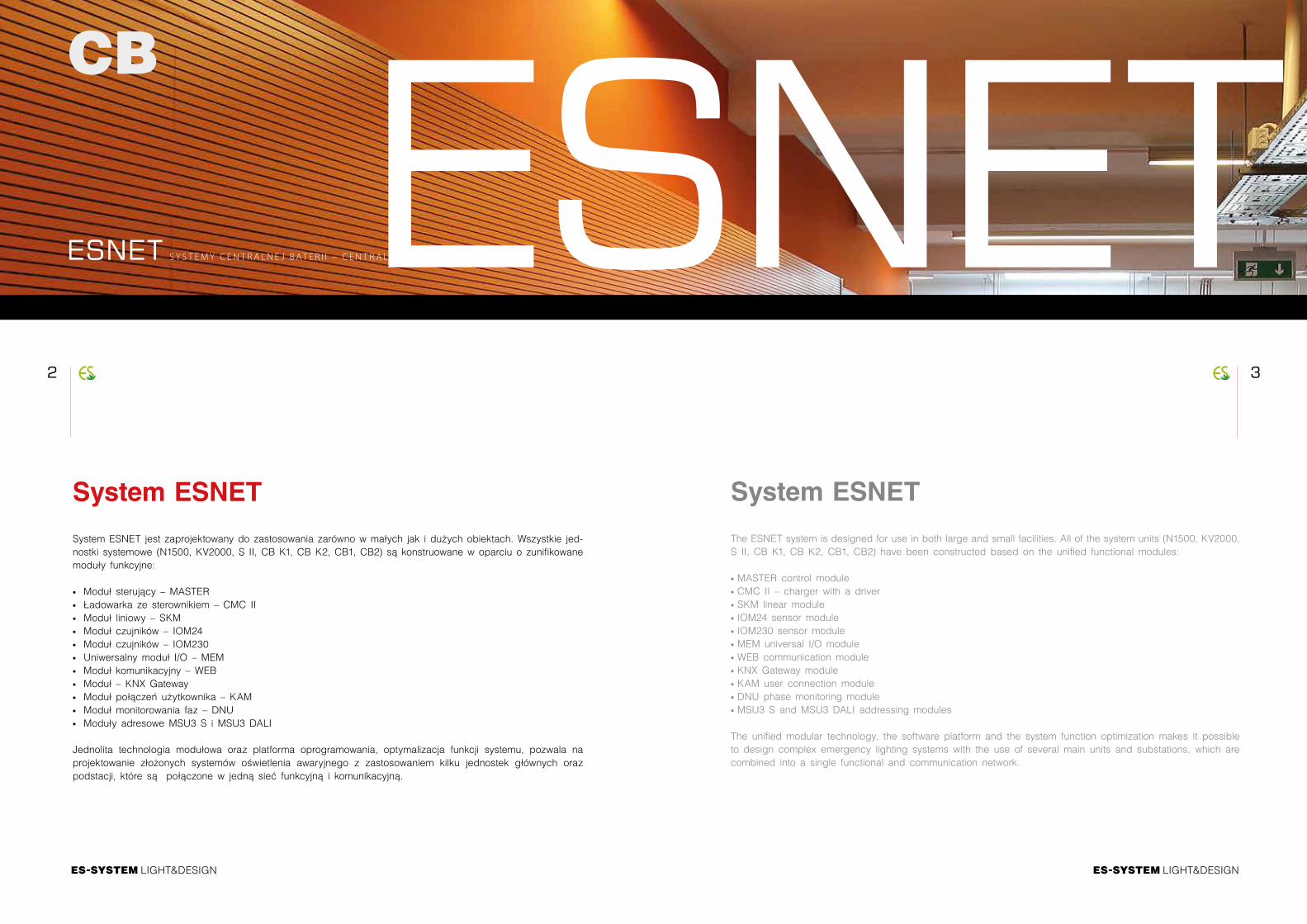
System ESNET jest zaprojektowany do zastosowania zarówno w małych jak i dużych obiektach. Wszystkie jed-nostki systemowe (N1500, KV2000, S II, CB K1, CB K2, CB1, CB2) są konstruowane w oparciu o zunifikowane moduły funkcyjne: ∙ Moduł sterujący – MASTER ∙ Ładowarka ze sterownikiem – CMC II ∙ Moduł liniowy – SKM ∙ Moduł czujników – IOM24 ∙ Moduł czujników – IOM230 ∙ Uniwersalny moduł I/O – MEM ∙ Moduł komunikacyjny – WEB ∙ Moduł – KNX Gateway ∙ Moduł połączeń użytkownika – KAM ∙ Moduł monitorowania faz – DNU ∙ Moduły adresowe MSU3 S i MSU3 DALI
Jednolita technologia modułowa oraz platforma oprogramowania, optymalizacja funkcji systemu, pozwala na projektowanie złożonych systemów oświetlenia awaryjnego z zastosowaniem kilku jednostek głównych oraz podstacji, które są połączone w jedną sieć funkcyjną i komunikacyjną.
System ESNET
The ESNET system is designed for use in both large and small facilities. All of the system units (N1500, KV2000, S II, CB K1, CB K2, CB1, CB2) have been constructed based on the unified functional modules: ∙ MASTER control module ∙ CMC II – charger with a driver ∙ SKM linear module ∙ IOM24 sensor module ∙ IOM230 sensor module ∙ MEM universal I/O module ∙ WEB communication module ∙ KNX Gateway module ∙ KAM user connection module ∙ DNU phase monitoring module ∙ MSU3 S and MSU3 DALI addressing modules
The unified modular technology, the software platform and the system function optimization makes it possible to design complex emergency lighting systems with the use of several main units and substations, which are combined into a single functional and communication network.
ESNET S Y S T E M Y C E N T R A L N E J B AT E R I I – C E N T R A L B AT T E R Y S Y S T E M SESNET
CB
LIGHT&DESIGN LIGHT&DESIGN
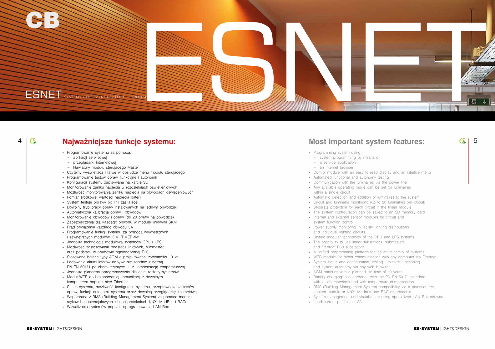
4 5Most important system features: ∙ Programming system using:
– system programming by means of – a service application – an Internet browser
∙ Control module with an easy to read display and an intuitive menu ∙ Automated functional and autonomy testing ∙ Communication with the luminaires via the power line ∙ Any available operating mode can be set for luminaires within a single circuit
∙ Automatic detection and addition of luminaires to the system ∙ Circuit and luminaire monitoring (up to 20 luminaires per circuit) ∙ Separate protection for each circuit in the linear module ∙ The system configuration can be saved to an SD memory card ∙ Internal and external sensor modules for circuit and system function control
∙ Power supply monitoring in facility lighting distributions and individual lighting circuits.
∙ Unified modular technology of the CPU and LPS systems ∙ The possibility to use linear substations, submasters, and fireproof E30 substations
∙ A unified programming platform for the entire family of systems ∙ WEB module for direct communication with any computer via Ethernet ∙ System status and configuration, testing luminaire functioning and system autonomy via any web browser
∙ AGM batteries with a planned life time of 10 years ∙ Battery charging in accordance with the PN-EN 50171 standard with UI characteristic and with temperature compensation.
∙ BMS (Building Management System) compatibility via a potential-free contact module or KNX, Modbus and BACnet protocols
∙ System management and visualization using specialized LAN Box software ∙ Load current per circuit: 3A
Najważniejsze funkcje systemu: ∙ Programowanie systemu za pomocą:
– aplikacji serwisowej – przeglądarki internetowej – klawiatury modułu sterującego Master
∙ Czytelny wyświetlacz i łatwe w obsłudze menu modułu sterującego ∙ Programowanie testów opraw, funkcyjne i autonomii ∙ Konfiguracji systemu zapisywana na karcie SD ∙ Monitorowanie zaniku napięcia w rozdzielniach oświetleniowych ∙ Możliwość monitorowania zaniku napięcia na obwodach oświetleniowych ∙ Pomiar środkowej wartości napięcia baterii ∙ System testuje oprawy po linii zasilającej ∙ Dowolny tryb pracy opraw instalowanych na jednym obwodzie ∙ Automatyczna kalibracja opraw i obwodów ∙ Monitorowanie obwodów i opraw (do 20 opraw na obwodzie) ∙ Zabezpieczenia dla każdego obwodu w module liniowym SKM ∙ Prąd obciążenia każdego obwodu 3A ∙ Programowanie funkcji systemu za pomocą wewnętrznych i zewnętrznych modułów IOM, TIMER-ów
∙ Jednolita technologia modułowa systemów CPU i LPS ∙ Możliwość zastosowania podstacji liniowych, submaster oraz podstacji w obudowie ognioodpornej E30
∙ Stosowane baterie typy AGM o projektowanej żywotności 10 lat ∙ Ładowanie akumulatorów odbywa się zgodnie z normą PN-EN 50171 po charakterystyce UI z kompensacją temperaturową
∙ Jednolita platforma oprogramowania dla całej rodziny systemów ∙ Moduł WEB do bezpośredniej komunikacji z dowolnym komputerem poprzez sieć Ethernet
∙ Status systemu, możliwość konfiguracji systemu, przeprowadzenia testów opraw, funkcjii autonomii systemu przez dowolną przeglądarkę internetową
∙ Współpraca z BMS (Building Management System) za pomocą modułu styków bezpotencjałowych lub po protokołach KNX, ModBus i BACnet
∙ Wizualizacja systemów poprzez oprogramowanie LAN Box
ESNET S Y S T E M Y C E N T R A L N E J B AT E R I I – C E N T R A L B AT T E R Y S Y S T E M SESNET
CB
LIGHT&DESIGN LIGHT&DESIGN
6 7
ESNET – N1500
CBS Y S T E M Y C E N T R A L N E J B AT E R I I – C E N T R A L B AT T E R Y S Y S T E M S
STACJE STATIONS
ESNET – KV2000
CBS Y S T E M Y C E N T R A L N E J B AT E R I I – C E N T R A L B AT T E R Y S Y S T E M S
STACJE STATIONS
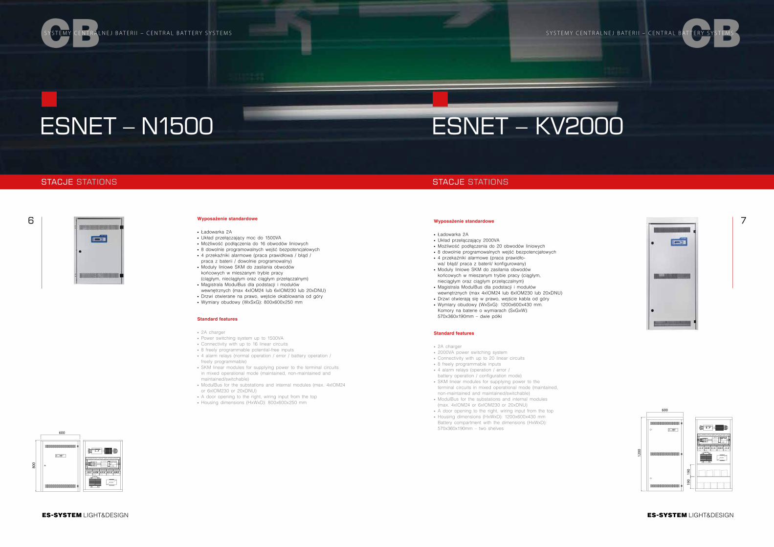
Wyposażenie standardowe
∙ Ładowarka 2A ∙ Układ przełączający moc do 1500VA ∙ Możliwość podłączenia do 16 obwodów liniowych ∙ 8 dowolnie programowalnych wejść bezpotencjałowych ∙ 4 przekaźniki alarmowe (praca prawidłowa / błąd / praca z baterii / dowolnie programowalny)
∙ Moduły liniowe SKM do zasilania obwodów końcowych w mieszanym trybie pracy (ciągłym, nieciągłym oraz ciągłym przełączalnym)
∙ Magistrala ModulBus dla podstacji i modułów wewnętrznych (max 4xIOM24 lub 6xIOM230 lub 20xDNU)
∙ Drzwi otwierane na prawo, wejście okablowania od góry ∙ Wymiary obudowy (WxSxG): 800x600x250 mm
Standard features
∙ 2A charger ∙ Power switching system up to 1500VA ∙ Connectivity with up to 16 linear circuits ∙ 8 freely programmable potential-free inputs ∙ 4 alarm relays (normal operation / error / battery operation / freely programmable)
∙ SKM linear modules for supplying power to the terminal circuits in mixed operational mode (maintained, non-maintained and maintained/switchable)
∙ ModulBus for the substations and internal modules (max. 4xIOM24 or 6xIOM230 or 20xDNU)
∙ A door opening to the right, wiring input from the top ∙ Housing dimensions (HxWxD): 800x600x250 mm
Wyposażenie standardowe
∙ Ładowarka 2A ∙ Układ przełączający 2000VA ∙ Możliwość podłączenia do 20 obwodów liniowych ∙ 8 dowolnie programowalnych wejść bezpotencjałowych ∙ 4 przekaźniki alarmowe (praca prawidło-wa/ błąd/ praca z baterii/ konfigurowany)
∙ Moduły liniowe SKM do zasilania obwodów końcowych w mieszanym trybie pracy (ciągłym, nieciągłym oraz ciągłym przełączalnym)
∙ Magistrala ModulBus dla podstacji i modułów wewnętrznych (max 4xIOM24 lub 6xIOM230 lub 20xDNU)
∙ Drzwi otwierają się w prawo, wejście kabla od góry ∙ Wymiary obudowy (WxSxG): 1200x600x430 mm. Komory na baterie o wymiarach (SxGxW): 570x360x190mm – dwie półki
Standard features
∙ 2A charger ∙ 2000VA power switching system ∙ Connectivity with up to 20 linear circuits ∙ 8 freely programmable inputs ∙ 4 alarm relays (operation / error / battery operation / configuration mode)
∙ SKM linear modules for supplying power to the terminal circuits in mixed operational mode (maintained, non-maintained and maintained/switchable)
∙ ModulBus for the substations and internal modules (max. 4xIOM24 or 6xIOM230 or 20xDNU)
∙ A door opening to the right, wiring input from the top ∙ Housing dimensions (HxWxD): 1200x600x430 mm Battery compartment with the dimensions (HxWxD): 570x360x190mm – two shelves
600
800
600
1200
190
190
LIGHT&DESIGN
8 9
LIGHT&DESIGN
CBS Y S T E M Y C E N T R A L N E J B AT E R I I – C E N T R A L B AT T E R Y S Y S T E M S
ESNET – S II
STACJE STATIONS
CBS Y S T E M Y C E N T R A L N E J B AT E R I I – C E N T R A L B AT T E R Y S Y S T E M S
STACJE STATIONS
ESNET – CB K1
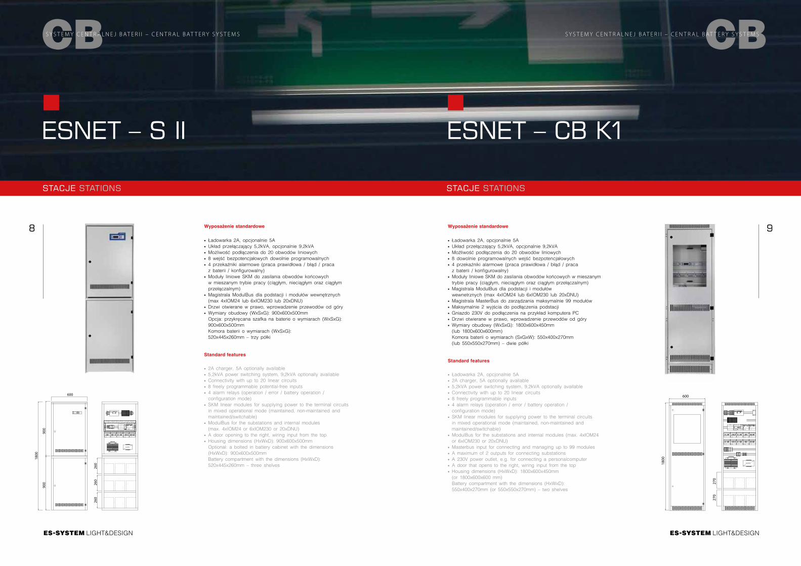
Wyposażenie standardowe
∙ Ładowarka 2A, opcjonalnie 5A ∙ Układ przełączający 5,2kVA, opcjonalnie 9,2kVA ∙ Możliwość podłączenia do 20 obwodów liniowych ∙ 8 wejść bezpotencjałowych dowolnie programowalnych ∙ 4 przekaźniki alarmowe (praca prawidłowa / błąd / praca z baterii / konfigurowalny)
∙ Moduły liniowe SKM do zasilania obwodów końcowych w mieszanym trybie pracy (ciągłym, nieciągłym oraz ciągłym przełączalnym)
∙ Magistrala ModulBus dla podstacji i modułów wewnętrznych (max 4xIOM24 lub 6xIOM230 lub 20xDNU)
∙ Drzwi otwierane w prawo, wprowadzenie przewodów od góry ∙ Wymiary obudowy (WxSxG): 900x600x500mm Opcja: przykręcana szafka na baterie o wymiarach (WxSxG): 900x600x500mmKomora baterii o wymiarach (WxSxG): 520x445x260mm – trzy półki
Standard features
∙ 2A charger, 5A optionally available ∙ 5,2kVA power switching system, 9,2kVA optionally available ∙ Connectivity with up to 20 linear circuits ∙ 8 freely programmable potential-free inputs ∙ 4 alarm relays (operation / error / battery operation / configuration mode)
∙ SKM linear modules for supplying power to the terminal circuits in mixed operational mode (maintained, non-maintained and maintained/switchable)
∙ ModulBus for the substations and internal modules (max. 4xIOM24 or 6xIOM230 or 20xDNU)
∙ A door opening to the right, wiring input from the top ∙ Housing dimensions (HxWxD): 900x600x500mm Optional: a bolted in battery cabinet with the dimensions (HxWxD): 900x600x500mmBattery compartment with the dimensions (HxWxD): 520x445x260mm – three shelves
Wyposażenie standardowe
∙ Ładowarka 2A, opcjonalnie 5A ∙ Układ przełączający 5,2kVA, opcjonalnie 9,2kVA ∙ Możliwość podłączenia do 20 obwodów liniowych ∙ 8 dowolnie programowalnych wejść bezpotencjałowych ∙ 4 przekaźniki alarmowe (praca prawidłowa / błąd / praca z baterii / konfigurowalny)
∙ Moduły liniowe SKM do zasilania obwodów końcowych w mieszanym trybie pracy (ciągłym, nieciągłym oraz ciągłym przełączalnym)
∙ Magistrala ModulBus dla podstacji i modułów wewnetrznych (max 4xIOM24 lub 6xIOM230 lub 20xDNU)
∙ Magistrala MasterBus do zarządzania maksymalnie 99 modułów ∙ Maksymalnie 2 wyjścia do podłączenia podstacji ∙ Gniazdo 230V do podłączenia na przykład komputera PC ∙ Drzwi otwierane w prawo, wprowadzenie przewodów od góry ∙ Wymiary obudowy (WxSxG): 1800x600x450mm (lub 1800x600x600mm) Komora baterii o wymiarach (SxGxW): 550x400x270mm (lub 550x550x270mm) – dwie półki
Standard features
∙ Ładowarka 2A, opcjonalnie 5A ∙ 2A charger, 5A optionally available ∙ 5,2kVA power switching system, 9,2kVA optionally available ∙ Connectivity with up to 20 linear circuits ∙ 8 freely programmable inputs ∙ 4 alarm relays (operation / error / battery operation / configuration mode)
∙ SKM linear modules for supplying power to the terminal circuits in mixed operational mode (maintained, non-maintained and maintained/switchable)
∙ ModulBus for the substations and internal modules (max. 4xIOM24 or 6xIOM230 or 20xDNU)
∙ Masterbus input for connecting and managing up to 99 modules ∙ A maximum of 2 outputs for connecting substations ∙ A 230V power outlet, e.g. for connecting a personalcomputer ∙ A door that opens to the right, wiring input from the top ∙ Housing dimensions (HxWxD): 1800x600x450mm (or 1800x600x600 mm)Battery compartment with the dimensions (HxWxD): 550x400x270mm (or 550x550x270mm) – two shelves
600
1800
260
260
260
900
900
600
270
270
1800
LIGHT&DESIGN
10 11
LIGHT&DESIGN
CBS Y S T E M Y C E N T R A L N E J B AT E R I I – C E N T R A L B AT T E R Y S Y S T E M S
ESNET – CB K2
STACJE STATIONS
CBS Y S T E M Y C E N T R A L N E J B AT E R I I – C E N T R A L B AT T E R Y S Y S T E M S
STACJE STATIONS
ESNET – CB1
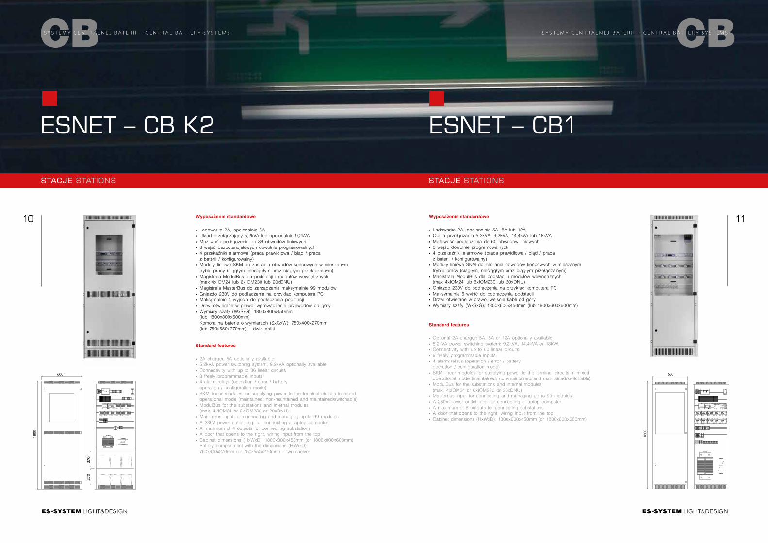
Wyposażenie standardowe
∙ Ładowarka 2A, opcjonalnie 5A, 8A lub 12A ∙ Opcja przełączania 5,2kVA, 9,2kVA, 14,4kVA lub 18kVA ∙ Możliwość podłączenia do 60 obwodów liniowych ∙ 8 wejść dowolnie programowalnych ∙ 4 przekaźniki alarmowe (praca prawidłowa / błąd / praca z baterii / konfigurowalny)
∙ Moduły liniowe SKM do zasilania obwodów końcowych w mieszanym trybie pracy (ciągłym, nieciągłym oraz ciągłym przełączalnym)
∙ Magistrala ModulBus dla podstacji i modułów wewnętrznych (max 4xIOM24 lub 6xIOM230 lub 20xDNU)
∙ Gniazdo 230V do podłączenia na przykład komputera PC ∙ Maksymalnie 6 wyjść do podłączenia podstacji ∙ Drzwi otwierane w prawo, wejście kabli od góry ∙ Wymiary szafy (WxSxG): 1800x600x450mm (lub 1800x600x600mm)
Standard features
∙ Optional 2A charger: 5A, 8A or 12A optionally available ∙ 5,2kVA power switching system: 9,2kVA, 14,4kVA or 18kVA ∙ Connectivity with up to 60 linear circuits ∙ 8 freely programmable inputs ∙ 4 alarm relays (operation / error / battery operation / configuration mode)
∙ SKM linear modules for supplying power to the terminal circuits in mixed operational mode (maintained, non-maintained and maintained/switchable)
∙ ModulBus for the substations and internal modules (max. 4xIOM24 or 6xIOM230 or 20xDNU)
∙ Masterbus input for connecting and managing up to 99 modules ∙ A 230V power outlet, e.g. for connecting a laptop computer ∙ A maximum of 6 outputs for connecting substations ∙ A door that opens to the right, wiring input from the top ∙ Cabinet dimensions (HxWxD): 1800x600x450mm (or 1800x600x600mm)
Wyposażenie standardowe
∙ Ładowarka 2A, opcjonalnie 5A ∙ Układ przełączający 5,2kVA lub opcjonalnie 9,2kVA ∙ Możliwość podłączenia do 36 obwodów liniowych ∙ 8 wejść bezpotencjałowych dowolnie programowalnych ∙ 4 przekaźniki alarmowe (praca prawidłowa / błąd / praca z baterii / konfigurowalny)
∙ Moduły liniowe SKM do zasilania obwodów końcowych w mieszanym trybie pracy (ciągłym, nieciągłym oraz ciągłym przełączalnym)
∙ Magistrala ModulBus dla podstacji i modułów wewnętrznych (max 4xIOM24 lub 6xIOM230 lub 20xDNU)
∙ Magistrala MasterBus do zarządzania maksymalnie 99 modułów ∙ Gniazdo 230V do podłączenia na przykład komputera PC ∙ Maksymalnie 4 wyjścia do podłączenia podstacji ∙ Drzwi otwierane w prawo, wprowadzenie przewodów od góry ∙ Wymiary szafy (WxSxG): 1800x800x450mm (lub 1800x800x600mm) Komora na baterie o wymiarach (SxGxW): 750x400x270mm (lub 750x550x270mm) – dwie półki
Standard features
∙ 2A charger, 5A optionally available ∙ 5,2kVA power switching system, 9,2kVA optionally available ∙ Connectivity with up to 36 linear circuits ∙ 8 freely programmable inputs ∙ 4 alarm relays (operation / error / battery operation / configuration mode)
∙ SKM linear modules for supplying power to the terminal circuits in mixed operational mode (maintained, non-maintained and maintained/switchable)
∙ ModulBus for the substations and internal modules (max. 4xIOM24 or 6xIOM230 or 20xDNU)
∙ Masterbus input for connecting and managing up to 99 modules ∙ A 230V power outlet, e.g. for connecting a laptop computer ∙ A maximum of 4 outputs for connecting substations ∙ A door that opens to the right, wiring input from the top ∙ Cabinet dimensions (HxWxD): 1800x800x450mm (or 1800x800x600mm) Battery compartment with the dimensions (HxWxD): 750x400x270mm (or 750x550x270mm) – two shelves
27
02
70
600
1800
600
1800
LIGHT&DESIGN
12 13
LIGHT&DESIGN
CBS Y S T E M Y C E N T R A L N E J B AT E R I I – C E N T R A L B AT T E R Y S Y S T E M S
ESNET – CB2
ESNET – CB2
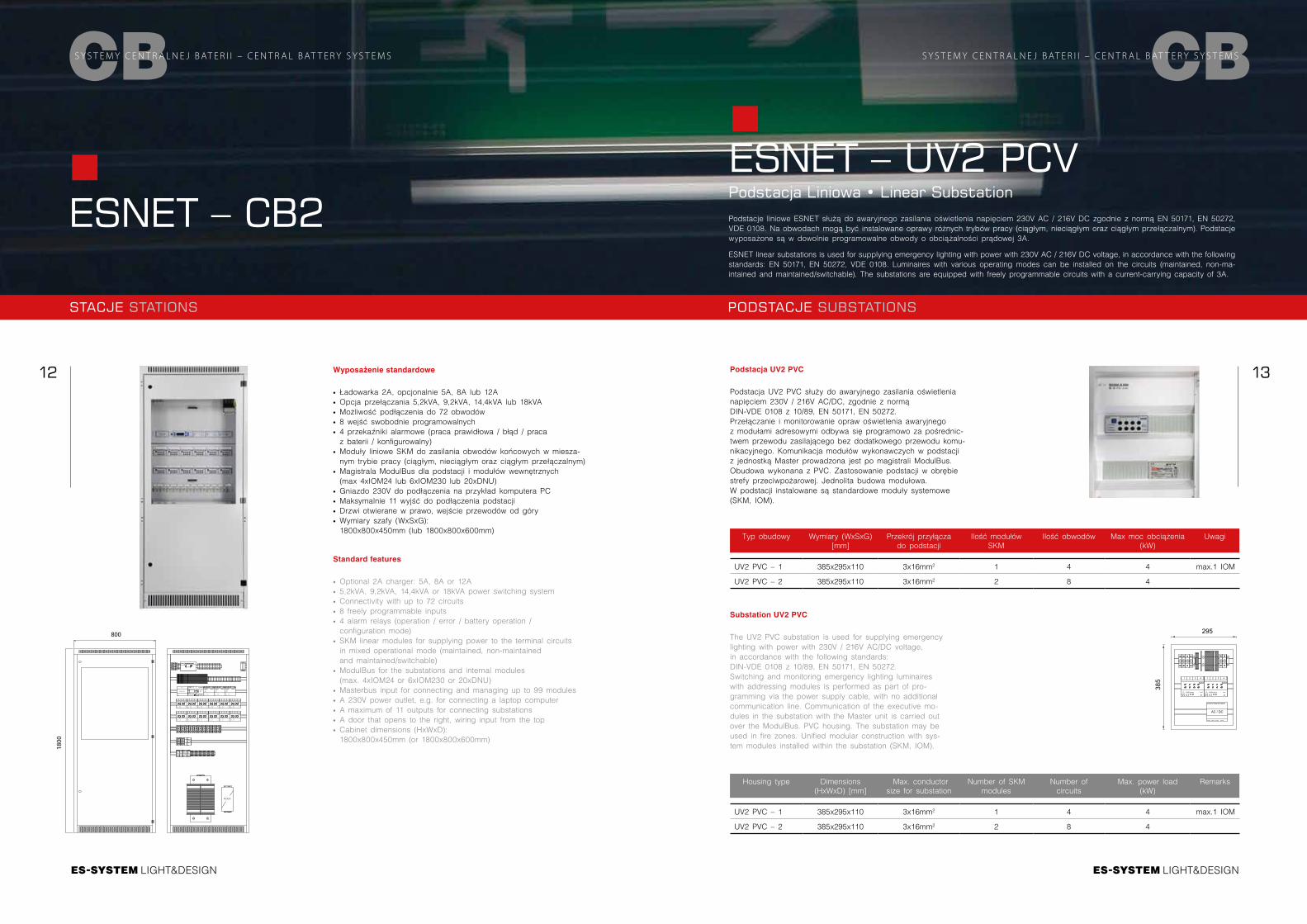
Wyposażenie standardowe
∙ Ładowarka 2A, opcjonalnie 5A, 8A lub 12A ∙ Opcja przełączania 5,2kVA, 9,2kVA, 14,4kVA lub 18kVA ∙ Możliwość podłączenia do 72 obwodów ∙ 8 wejść swobodnie programowalnych ∙ 4 przekaźniki alarmowe (praca prawidłowa / błąd / praca z baterii / konfigurowalny)
∙ Moduły liniowe SKM do zasilania obwodów końcowych w miesza-nym trybie pracy (ciągłym, nieciągłym oraz ciągłym przełączalnym)
∙ Magistrala ModulBus dla podstacji i modułów wewnętrznych (max 4xIOM24 lub 6xIOM230 lub 20xDNU)
∙ Gniazdo 230V do podłączenia na przykład komputera PC ∙ Maksymalnie 11 wyjść do podłączenia podstacji ∙ Drzwi otwierane w prawo, wejście przewodów od góry ∙ Wymiary szafy (WxSxG): 1800x800x450mm (lub 1800x800x600mm)
Standard features
∙ Optional 2A charger: 5A, 8A or 12A ∙ 5,2kVA, 9,2kVA, 14,4kVA or 18kVA power switching system ∙ Connectivity with up to 72 circuits ∙ 8 freely programmable inputs ∙ 4 alarm relays (operation / error / battery operation / configuration mode)
∙ SKM linear modules for supplying power to the terminal circuits in mixed operational mode (maintained, non-maintained and maintained/switchable)
∙ ModulBus for the substations and internal modules (max. 4xIOM24 or 6xIOM230 or 20xDNU)
∙ Masterbus input for connecting and managing up to 99 modules ∙ A 230V power outlet, e.g. for connecting a laptop computer ∙ A maximum of 11 outputs for connecting substations ∙ A door that opens to the right, wiring input from the top ∙ Cabinet dimensions (HxWxD): 1800x800x450mm (or 1800x800x600mm)
STACJE STATIONS PODSTACJE SUBSTATIONS
ESNET – UV2 PCVPodstacja Liniowa • Linear Substation
Podstacja UV2 PVC
Podstacja UV2 PVC służy do awaryjnego zasilania oświetlenia napięciem 230V / 216V AC/DC, zgodnie z normą DIN-VDE 0108 z 10/89, EN 50171, EN 50272.Przełączanie i monitorowanie opraw oświetlenia awaryjnego z modułami adresowymi odbywa się programowo za pośrednic-twem przewodu zasilającego bez dodatkowego przewodu komu-nikacyjnego. Komunikacja modułów wykonawczych w podstacji z jednostką Master prowadzona jest po magistrali ModulBus. Obudowa wykonana z PVC. Zastosowanie podstacji w obrębie strefy przeciwpożarowej. Jednolita budowa modułowa. W podstacji instalowane są standardowe moduły systemowe (SKM, IOM).
Substation UV2 PVC
The UV2 PVC substation is used for supplying emergency lighting with power with 230V / 216V AC/DC voltage, in accordance with the following standards: DIN-VDE 0108 z 10/89, EN 50171, EN 50272.Switching and monitoring emergency lighting luminaires with addressing modules is performed as part of pro-gramming via the power supply cable, with no additional communication line. Communication of the executive mo-dules in the substation with the Master unit is carried out over the ModulBus. PVC housing. The substation may be used in fire zones. Unified modular construction with sys-tem modules installed within the substation (SKM, IOM).
Typ obudowy Wymiary (WxSxG) [mm]
Przekrój przyłącza do podstacji
Ilość modułów SKM
Ilość obwodów Max moc obciążenia (kW)
Uwagi
UV2 PVC – 1 385x295x110 3x16mm2 1 4 4 max.1 IOM
UV2 PVC – 2 385x295x110 3x16mm2 2 8 4
Housing type Dimensions (HxWxD) [mm]
Max. conductor size for substation
Number of SKM modules
Number of circuits
Max. power load (kW)
Remarks
UV2 PVC – 1 385x295x110 3x16mm2 1 4 4 max.1 IOM
UV2 PVC – 2 385x295x110 3x16mm2 2 8 4
Podstacje liniowe ESNET służą do awaryjnego zasilania oświetlenia napięciem 230V AC / 216V DC zgodnie z normą EN 50171, EN 50272, VDE 0108. Na obwodach mogą być instalowane oprawy różnych trybów pracy (ciągłym, nieciągłym oraz ciągłym przełączalnym). Podstacje wyposażone są w dowolnie programowalne obwody o obciążalności prądowej 3A. ESNET linear substations is used for supplying emergency lighting with power with 230V AC / 216V DC voltage, in accordance with the following standards: EN 50171, EN 50272, VDE 0108. Luminaires with various operating modes can be installed on the circuits (maintained, non-ma-intained and maintained/switchable). The substations are equipped with freely programmable circuits with a current-carrying capacity of 3A.
CBS Y S T E M Y C E N T R A L N E J B AT E R I I – C E N T R A L B AT T E R Y S Y S T E M S
295
385
AC / DC
1 2 3 4
SKM
- +SV
24V/DC AC/DCBUS- +
ADRESS
1 2 3 4
SKM
- +SV
24V/DC AC/DCBUS- +
ADRESS
800
1800
LIGHT&DESIGN
14 15
LIGHT&DESIGN
CBS Y S T E M Y C E N T R A L N E J B AT E R I I – C E N T R A L B AT T E R Y S Y S T E M S
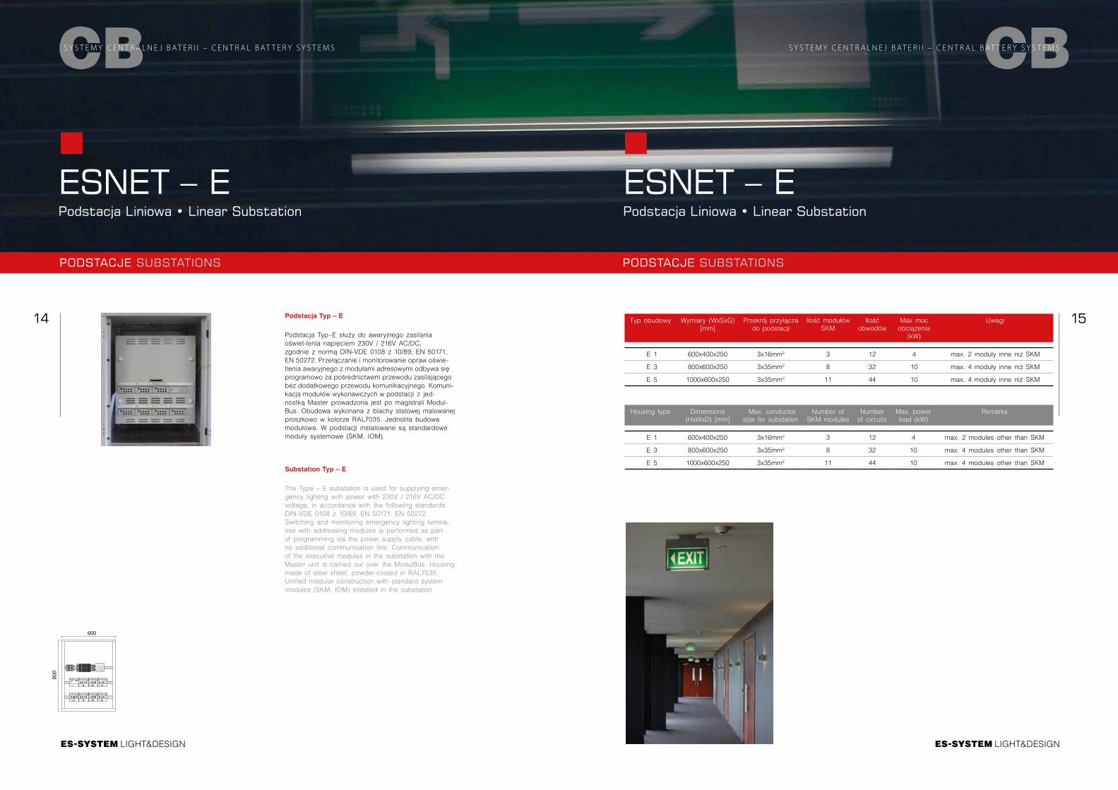
ESNET – EPodstacja Liniowa • Linear Substation
Podstacja Typ – E
Podstacja Typ–E służy do awaryjnego zasilania oświet-lenia napięciem 230V / 216V AC/DC, zgodnie z normą DIN-VDE 0108 z 10/89, EN 50171, EN 50272. Przełączanie i monitorowanie opraw oświe-tlenia awaryjnego z modułami adresowymi odbywa się programowo za pośrednictwem przewodu zasilającego bez dodatkowego przewodu komunikacyjnego. Komuni-kacja modułów wykonawczych w podstacji z jed- nostką Master prowadzona jest po magistrali Modul-Bus. Obudowa wykonana z blachy stalowej malowanej proszkowo w kolorze RAL7035. Jednolita budowa modułowa. W podstacji instalowane są standardowe moduły systemowe (SKM, IOM).
Substation Typ – E
The Type – E substation is used for supplying emer-gency lighting with power with 230V / 216V AC/DC voltage, in accordance with the following standards DIN-VDE 0108 z 10/89, EN 50171, EN 50272.Switching and monitoring emergency lighting lumina-ires with addressing modules is performed as part of programming via the power supply cable, with no additional communication line. Communication of the executive modules in the substation with the Master unit is carried out over the ModulBus. Housing made of steel sheet, powder-coated in RAL7035. Unified modular construction with standard system modules (SKM, IOM) installed in the substation.
PODSTACJE SUBSTATIONS
ESNET – EPodstacja Liniowa • Linear Substation
CBS Y S T E M Y C E N T R A L N E J B AT E R I I – C E N T R A L B AT T E R Y S Y S T E M S
Typ obudowy Wymiary (WxSxG) [mm]
Przekrój przyłącza do podstacji
Ilość modułów SKM
Ilość obwodów
Max moc obciążenia
(kW)
Uwagi
E 1 600x400x250 3x16mm2 3 12 4 max. 2 moduły inne niż SKM
E 3 800x600x250 3x35mm2 8 32 10 max. 4 moduły inne niż SKM
E 5 1000x600x250 3x35mm2 11 44 10 max. 4 moduły inne niż SKM
Housing type Dimensions (HxWxD) [mm]
Max. conductor size for substation
Number of SKM modules
Number of circuits
Max. power load (kW)
Remarks
E 1 600x400x250 3x16mm2 3 12 4 max. 2 modules other than SKM
E 3 800x600x250 3x35mm2 8 32 10 max. 4 modules other than SKM
E 5 1000x600x250 3x35mm2 11 44 10 max. 4 modules other than SKM
PODSTACJE SUBSTATIONS
600
800
E1 E2 E3 E4 E5 E6 E7 E8 E9 E10 E11 E12 E13 E14 E15 E16
IOM24
12
3
4
5
67
8
9
1011
12
13
14
15
1617
18
19
2021
22
23
24
25
2627
28
29
30
31
32
SV24V/DC BUS- + - +
1 2 3 4
SKM
- +SV
24V/DC AC/DCBUS- +
ADRESS
1 2 3 4
SKM
- +SV
24V/DC AC/DCBUS- +
ADRESS
1 2 3 4
SKM
- +SV
24V/DC AC/DCBUS- +
ADRESS
1 2 3 4
SKM
- +SV
24V/DC AC/DCBUS- +
ADRESS
1 2 3 4
SKM
- +SV
24V/DC AC/DCBUS- +
ADRESS
1 2 3 4
SKM
- +SV
24V/DC AC/DCBUS- +
ADRESS
1 2 3 4
SKM
- +SV
24V/DC AC/DCBUS- +
ADRESS
AC / DC
LIGHT&DESIGN
16 17
LIGHT&DESIGN
CBS Y S T E M Y C E N T R A L N E J B AT E R I I – C E N T R A L B AT T E R Y S Y S T E M S
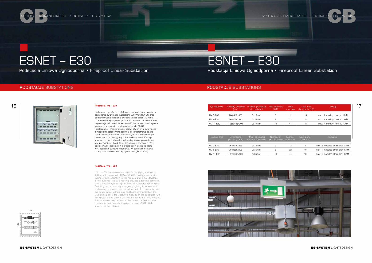
ESNET – E30Podstacja Liniowa Ogniodporna • Fireproof Linear Substation
ESNET – E30Podstacja Liniowa Ogniodporna • Fireproof Linear Substation
Podstacja Typ – E30
Podstacje typu UV ... – E30 służą do awaryjnego zasilania oświetlenia awaryjnego napięciem 230VAC/ 216VDC oraz podtrzymywanie działania systemu przez okres 30 minut od momentu wystąpienia pożaru w obiekcie. Obudowy E30 zapewniają odpowiednia szczelność i ochronę przed wysoka temperaturą zewnętrzna sięgającą aż do 850°C. Przełączanie i monitorowanie opraw oświetlenia awaryjnego z modułami adresowymi odbywa się programowo za po-średnictwem przewodów zasilająceych bez dodatkowego przewodu komunikacyjnego. Komunikacja modułów wy-konawczych w podstacji z jednostką Master prowadzona jest po magistrali Modulbus. Obudowa wykonana z PVC. Zastosowanie podstacji w obrębie strefy przeciwpożaro-wej. Jednolita budowa modułowa. W podstacji instalowa-ne są standardowe moduły systemowe (SKM, IOM).
Podstacja Typ – E30
UV ... – E30 substations are used for supplying emergency lighting with power with 230VAC/216VDC voltage and main-taining system operation for 30 minutes after a fire develops in the building. The E30 housing provides adequate tightness and protection against high external temperatures up to 850°C. Switching and monitoring emergency lighting luminaires with addressing modules is performed as part of programming via the power cable, without any additional communication line. Communication of the executive modules in the substation with the Master unit is carried out over the ModulBus. PVC housing. The substation may be used in fire zones. Unified modular construction with standard system modules (SKM, IOM) installed in the substation.
Typ obudowy Wymiary (WxSxG) [mm]
Przekrój przyłącza do podstacji
Ilość modułów SKM
Ilość obwodów
Max moc obciążenia (kW)
Uwagi
UV 3-E30 768x418x396 3x16mm2 3 12 4 max. 2 moduły inne niż SKM
UV 8-E30 768x668x396 3x35mm2 8 32 10 max. 4 moduły inne niż SKM
UV 11-E30 1068x668x396 3x35mm2 11 44 10 max. 4 moduły inne niż SKM
Housing type Dimensions (HxWxD) [mm]
Max. conductor size for substation
Number of SKM modules
Number of circuits
Max. power load (kW)
Remarks
UV 3-E30 768x418x396 3x16mm2 3 12 4 max. 2 modules other than SKM
UV 8-E30 768x668x396 3x35mm2 8 32 10 max. 4 modules other than SKM
UV 11-E30 1068x668x396 3x35mm2 11 44 10 max. 4 modules other than SKM
CBS Y S T E M Y C E N T R A L N E J B AT E R I I – C E N T R A L B AT T E R Y S Y S T E M S
PODSTACJE SUBSTATIONS PODSTACJE SUBSTATIONS
668
768
E1 E2 E3 E4 E5 E6 E7 E8 E9 E10 E11 E12 E13 E14 E15 E16
IOM24
12
34
56
78
910
1112
1314
1516
1718
1920
2122
2324
2526
2728
2930
3132
SV24V/DC BUS- + - +
1 2 3 4
SKM
- +SV
24V/DC AC/DCBUS- +
ADRESS
1 2 3 4
SKM
- +SV
24V/DC AC/DCBUS- +
ADRESS
1 2 3 4
SKM
- +SV
24V/DC AC/DCBUS- +
ADRESS
1 2 3 4
SKM
- +SV
24V/DC AC/DCBUS- +
ADRESS
1 2 3 4
SKM
- +SV
24V/DC AC/DCBUS- +
ADRESS
1 2 3 4
SKM
- +SV
24V/DC AC/DCBUS- +
ADRESS
1 2 3 4
SKM
- +SV
24V/DC AC/DCBUS- +
ADRESS
AC / DC
LIGHT&DESIGN
18 19
LIGHT&DESIGN
CBS Y S T E M Y C E N T R A L N E J B AT E R I I – C E N T R A L B AT T E R Y S Y S T E M S
OPROGRAMOWANIE SOFTWARE
ESNET Oprogramowanie wizualizacyjne • Visualization software
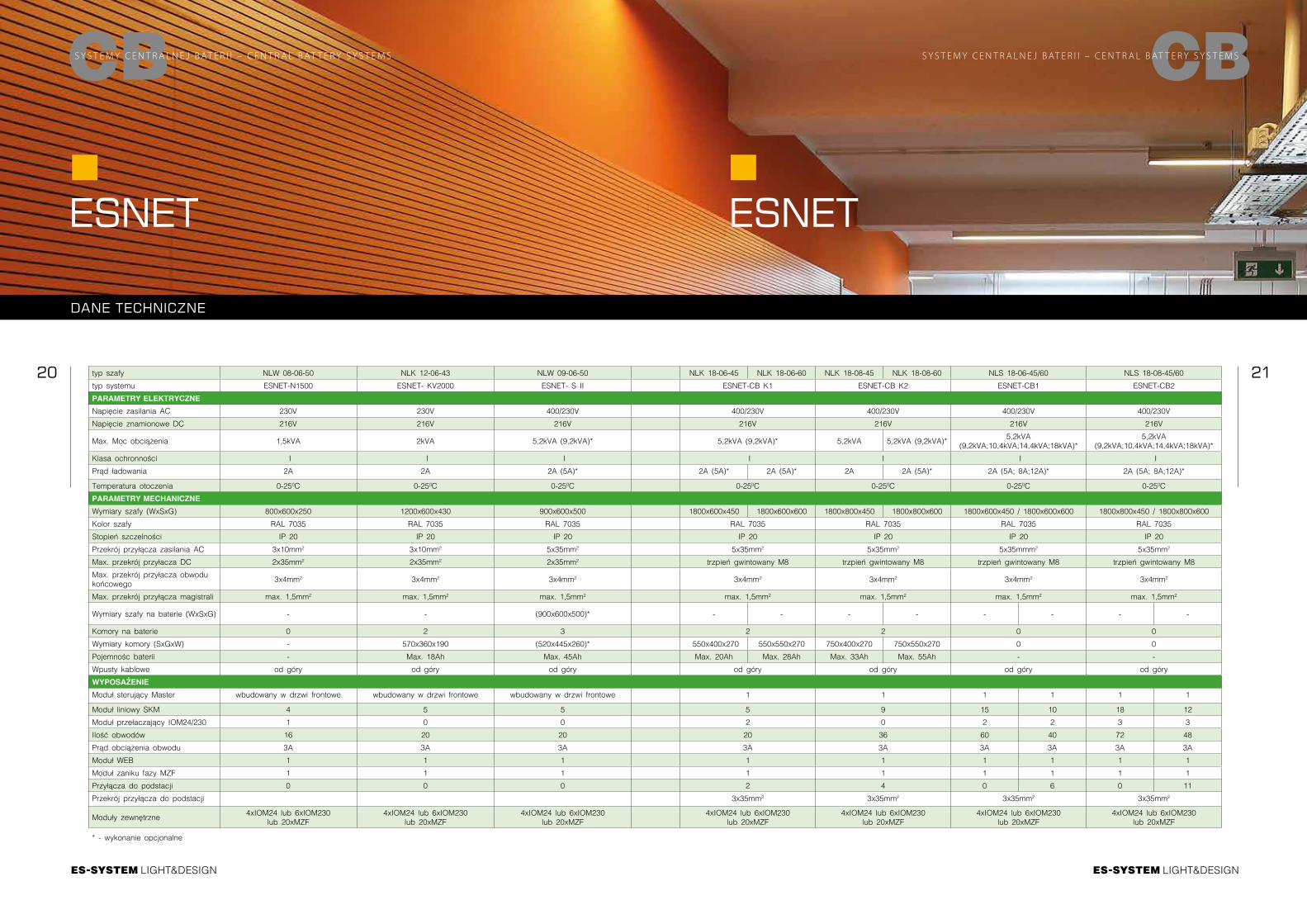
Oprogramowanie wizualizacyjne
Oprogramowanie wizualizacyjne pozwala na pełną konfigurację systemu oraz odczytanie statusów zainstalowanych urządzeń. Oprogramowanie jest spójne dla wszystkich typów i jednostek systemu ESNET. Wizualizację systemu możemy otrzymać za pomocą modułów WEB, LAN-Box lub IPC-Box
Oprogramowanie to pozwala na: ∙ Intuicyjne programowanie systemu ∙ Import opisów opraw z programu Excel ∙ Wczytanie kompletnych obwodów ∙ Wczytanie modułów przełączania ∙ Wczytanie zainstalowanych opraw ∙ Opisy tekstowe opraw ∙ Automatyczne skanowanie opraw (MSÜ3) ∙ Ustalanie terminów testów ∙ Opcji przełączania
Visualization software
Visualization software makes it possible to fully configure the system and access information about the status of the installed devices. The software is consistent for all ESNET system types and units. System visualization can be ob-tained by using WEB, LAN-Box or IPC-Box modules.
This software makes it possible to: ∙ Intuitively program the system ∙ Import luminaire descriptions from Excel files ∙ Load complete circuits ∙ Load switching modules ∙ Load installed luminaires ∙ Enter luminaire descriptions ∙ Automatically scan luminaires (MSÜ3) ∙ Set up testing dates ∙ Set switching options
INSTALACJA INSTALATION
ESNET Schemat instalacyjny • System connection scheme
CBS Y S T E M Y C E N T R A L N E J B AT E R I I – C E N T R A L B AT T E R Y S Y S T E M S
LIGHT&DESIGN
20 21
LIGHT&DESIGN
CBS Y S T E M Y C E N T R A L N E J B AT E R I I – C E N T R A L B AT T E R Y S Y S T E M S
DANE TECHNICZNE
ESNET ESNET
CBS Y S T E M Y C E N T R A L N E J B AT E R I I – C E N T R A L B AT T E R Y S Y S T E M S
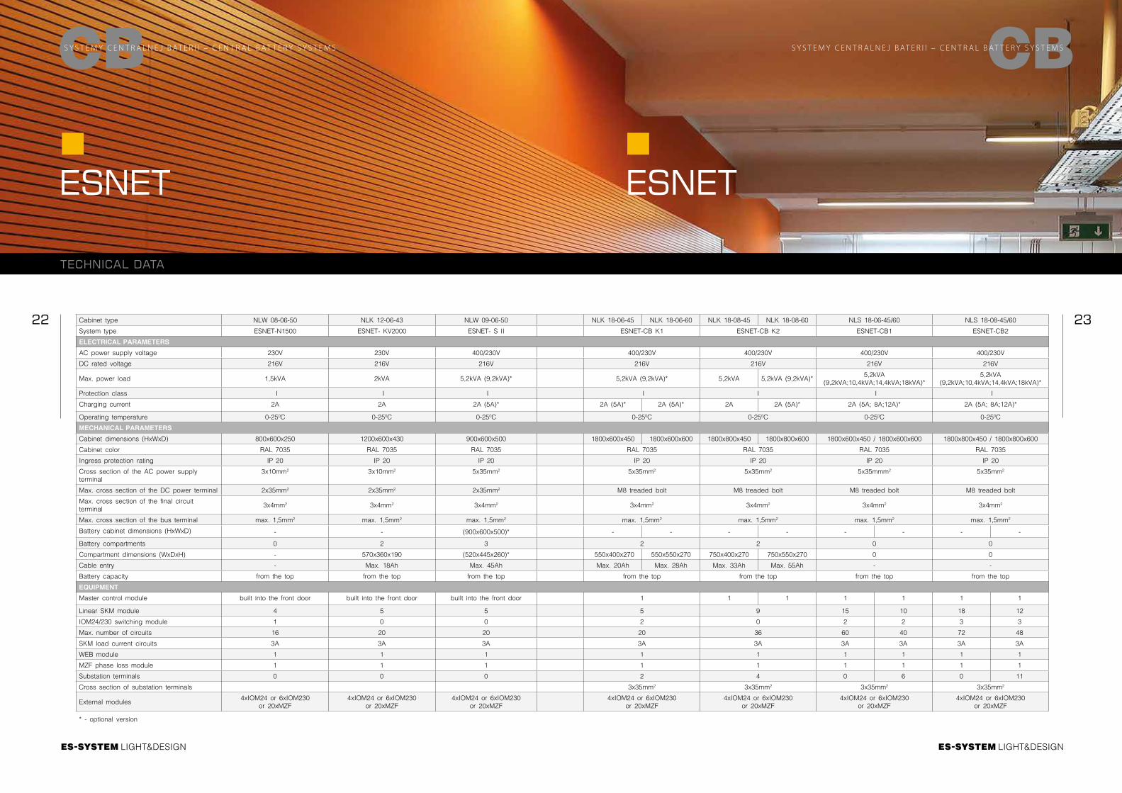
typ szafy NLW 08-06-50 NLK 12-06-43 NLW 09-06-50 NLK 18-06-45 NLK 18-06-60 NLK 18-08-45 NLK 18-08-60 NLS 18-06-45/60 NLS 18-08-45/60
typ systemu ESNET-N1500 ESNET- KV2000 ESNET- S II ESNET-CB K1 ESNET-CB K2 ESNET-CB1 ESNET-CB2
PARAMETRY ELEKTRYCZNE
Napięcie zasilania AC 230V 230V 400/230V 400/230V 400/230V 400/230V 400/230V
Napięcie znamionowe DC 216V 216V 216V 216V 216V 216V 216V
Max. Moc obciążenia 1,5kVA 2kVA 5,2kVA (9,2kVA)* 5,2kVA (9,2kVA)* 5,2kVA 5,2kVA (9,2kVA)*5,2kVA
(9,2kVA;10,4kVA;14,4kVA;18kVA)*5,2kVA
(9,2kVA;10,4kVA;14,4kVA;18kVA)*
Klasa ochronności I I I I I I I
Prąd ładowania 2A 2A 2A (5A)* 2A (5A)* 2A (5A)* 2A 2A (5A)* 2A (5A; 8A;12A)* 2A (5A; 8A;12A)*
Temperatura otoczenia 0-250C 0-250C 0-250C 0-250C 0-250C 0-250C 0-250C
PARAMETRY MECHANICZNE
Wymiary szafy (WxSxG) 800x600x250 1200x600x430 900x600x500 1800x600x450 1800x600x600 1800x800x450 1800x800x600 1800x600x450 / 1800x600x600 1800x800x450 / 1800x800x600
Kolor szafy RAL 7035 RAL 7035 RAL 7035 RAL 7035 RAL 7035 RAL 7035 RAL 7035
Stopień szczelności IP 20 IP 20 IP 20 IP 20 IP 20 IP 20 IP 20
Przekrój przyłącza zasilania AC 3x10mm2 3x10mm2 5x35mm2 5x35mm2 5x35mm2 5x35mmm2 5x35mm2
Max. przekrój przyłacza DC 2x35mm2 2x35mm2 2x35mm2 trzpień gwintowany M8 trzpień gwintowany M8 trzpień gwintowany M8 trzpień gwintowany M8
Max. przekrój przyłacza obwodu końcowego
3x4mm2 3x4mm2 3x4mm2 3x4mm2 3x4mm2 3x4mm2 3x4mm2
Max. przekrój przyłącza magistrali max. 1,5mm2 max. 1,5mm2 max. 1,5mm2 max. 1,5mm2 max. 1,5mm2 max. 1,5mm2 max. 1,5mm2
Wymiary szafy na baterie (WxSxG) - - (900x600x500)* - - - - - - - -
Komory na baterie 0 2 3 2 2 0 0
Wymiary komory (SxGxW) - 570x360x190 (520x445x260)* 550x400x270 550x550x270 750x400x270 750x550x270 0 0
Pojemnośc baterii - Max. 18Ah Max. 45Ah Max. 20Ah Max. 28Ah Max. 33Ah Max. 55Ah - -
Wpusty kablowe od góry od góry od góry od góry od góry od góry od góry
WYPOSAŻENIE
Moduł sterujący Master wbudowany w drzwi frontowe wbudowany w drzwi frontowe wbudowany w drzwi frontowe 1 1 1 1 1 1
Moduł liniowy SKM 4 5 5 5 9 15 10 18 12
Moduł przełaczający IOM24/230 1 0 0 2 0 2 2 3 3
Ilość obwodów 16 20 20 20 36 60 40 72 48
Prąd obciążenia obwodu 3A 3A 3A 3A 3A 3A 3A 3A 3A
Moduł WEB 1 1 1 1 1 1 1 1 1
Moduł zaniku fazy MZF 1 1 1 1 1 1 1 1 1
Przyłącza do podstacji 0 0 0 2 4 0 6 0 11
Przekrój przyłącza do podstacji 3x35mm2 3x35mm2 3x35mm2 3x35mm2
Moduły zewnętrzne4xIOM24 lub 6xIOM230
lub 20xMZF4xIOM24 lub 6xIOM230
lub 20xMZF4xIOM24 lub 6xIOM230
lub 20xMZF4xIOM24 lub 6xIOM230
lub 20xMZF4xIOM24 lub 6xIOM230
lub 20xMZF4xIOM24 lub 6xIOM230
lub 20xMZF4xIOM24 lub 6xIOM230
lub 20xMZF
* - wykonanie opcjonalne
LIGHT&DESIGN
22 23
LIGHT&DESIGN
CBS Y S T E M Y C E N T R A L N E J B AT E R I I – C E N T R A L B AT T E R Y S Y S T E M S
TECHNICAL DATA
ESNET ESNET
CBS Y S T E M Y C E N T R A L N E J B AT E R I I – C E N T R A L B AT T E R Y S Y S T E M S
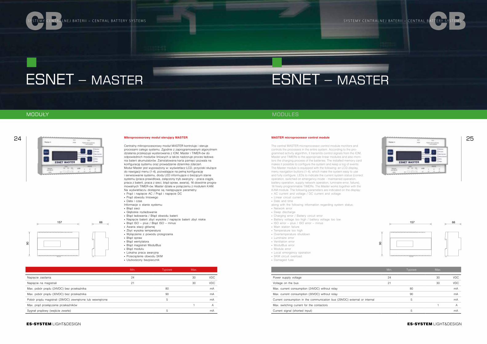
Cabinet type NLW 08-06-50 NLK 12-06-43 NLW 09-06-50 NLK 18-06-45 NLK 18-06-60 NLK 18-08-45 NLK 18-08-60 NLS 18-06-45/60 NLS 18-08-45/60
System type ESNET-N1500 ESNET- KV2000 ESNET- S II ESNET-CB K1 ESNET-CB K2 ESNET-CB1 ESNET-CB2
ELECTRICAL PARAMETERS
AC power supply voltage 230V 230V 400/230V 400/230V 400/230V 400/230V 400/230V
DC rated voltage 216V 216V 216V 216V 216V 216V 216V
Max. power load 1,5kVA 2kVA 5,2kVA (9,2kVA)* 5,2kVA (9,2kVA)* 5,2kVA 5,2kVA (9,2kVA)*5,2kVA
(9,2kVA;10,4kVA;14,4kVA;18kVA)*5,2kVA
(9,2kVA;10,4kVA;14,4kVA;18kVA)*
Protection class I I I I I I I
Charging current 2A 2A 2A (5A)* 2A (5A)* 2A (5A)* 2A 2A (5A)* 2A (5A; 8A;12A)* 2A (5A; 8A;12A)*
Operating temperature 0-250C 0-250C 0-250C 0-250C 0-250C 0-250C 0-250C
MECHANICAL PARAMETERS
Cabinet dimensions (HxWxD) 800x600x250 1200x600x430 900x600x500 1800x600x450 1800x600x600 1800x800x450 1800x800x600 1800x600x450 / 1800x600x600 1800x800x450 / 1800x800x600
Cabinet color RAL 7035 RAL 7035 RAL 7035 RAL 7035 RAL 7035 RAL 7035 RAL 7035
Ingress protection rating IP 20 IP 20 IP 20 IP 20 IP 20 IP 20 IP 20
Cross section of the AC power supply terminal
3x10mm2 3x10mm2 5x35mm2 5x35mm2 5x35mm2 5x35mmm2 5x35mm2
Max. cross section of the DC power terminal 2x35mm2 2x35mm2 2x35mm2 M8 treaded bolt M8 treaded bolt M8 treaded bolt M8 treaded bolt
Max. cross section of the final circuit terminal
3x4mm2 3x4mm2 3x4mm2 3x4mm2 3x4mm2 3x4mm2 3x4mm2
Max. cross section of the bus terminal max. 1,5mm2 max. 1,5mm2 max. 1,5mm2 max. 1,5mm2 max. 1,5mm2 max. 1,5mm2 max. 1,5mm2
Battery cabinet dimensions (HxWxD) - - (900x600x500)* - - - - - - - -
Battery compartments 0 2 3 2 2 0 0
Compartment dimensions (WxDxH) - 570x360x190 (520x445x260)* 550x400x270 550x550x270 750x400x270 750x550x270 0 0
Cable entry - Max. 18Ah Max. 45Ah Max. 20Ah Max. 28Ah Max. 33Ah Max. 55Ah - -
Battery capacity from the top from the top from the top from the top from the top from the top from the top
EQUIPMENT
Master control module built into the front door built into the front door built into the front door 1 1 1 1 1 1 1
Linear SKM module 4 5 5 5 9 15 10 18 12
IOM24/230 switching module 1 0 0 2 0 2 2 3 3
Max. number of circuits 16 20 20 20 36 60 40 72 48
SKM load current circuits 3A 3A 3A 3A 3A 3A 3A 3A 3A
WEB module 1 1 1 1 1 1 1 1 1
MZF phase loss module 1 1 1 1 1 1 1 1 1
Substation terminals 0 0 0 2 4 0 6 0 11
Cross section of substation terminals 3x35mm2 3x35mm2 3x35mm2 3x35mm2
External modules4xIOM24 or 6xIOM230
or 20xMZF4xIOM24 or 6xIOM230
or 20xMZF4xIOM24 or 6xIOM230
or 20xMZF4xIOM24 or 6xIOM230
or 20xMZF4xIOM24 or 6xIOM230
or 20xMZF4xIOM24 or 6xIOM230
or 20xMZF4xIOM24 or 6xIOM230
or 20xMZF
* - optional version
LIGHT&DESIGN
24 25
LIGHT&DESIGN
CBS Y S T E M Y C E N T R A L N E J B AT E R I I – C E N T R A L B AT T E R Y S Y S T E M S
ESNET – MASTER
Mikroprocesorowy moduł sterujący MASTER
Centralny mikroprocesorowy moduł MASTER kontroluje i steruje procesami całego systemu. Zgodnie z zaprogramowanym algorytmem działania przekazuje wysterowania z IOM, Master i TIMER-ów do odpowiednich modułów liniowych a także nadzoruje proces ładowa- nia baterii akumulatorów. Zainstalowana karta pamięci pozwala na konfigurację systemu oraz prowadzenie dziennika zdarzeń. Moduł Master jest wyposażony w: wyświetlacz LCD, przyciski służące do nawigacji menu (1-4), pozwalające na pełną konfigurację i serwisowanie systemu, diody LED informujące o bieżącym stanie systemu (praca prawidłowa, załączony tryb awaryjny – praca ciągła, praca z baterii, praca z sieci, błąd opraw, awaria), 16 dowolnie progra-mowalnych TIMER-ów. Master działa w połączeniu z modułem KAM. Na wyświetlaczu dostępne są następujące parametry: ∙ Prąd i napięcie AC / Prąd i napięcie DC ∙ Prąd obwodu liniowego ∙ Data i czasInformacje o stanie systemu: ∙ Błąd sieci ∙ Głębokie rozładowanie ∙ Błąd ładowania / Błąd obwodu baterii ∙ Napięcie baterii zbyt wysokie / napięcie baterii zbyt niskie ∙ Błąd ISO – plus / Błąd ISO – minus ∙ Awaria stacji głównej ∙ Zbyt wysoka temperatura ∙ Wyłączenie z powodu przegrzania ∙ Błąd opraw ∙ Błąd wentylatora ∙ Błąd magistrali ModulBus ∙ Błąd modułu ∙ Lokalna praca awaryjna ∙ Przeciążenie obwodu SKM ∙ Uszkodzony bezpiecznik
ESNET – MASTER
CBS Y S T E M Y C E N T R A L N E J B AT E R I I – C E N T R A L B AT T E R Y S Y S T E M S
MASTER microprocessor control module
The central MASTER microprocessor control module monitors and controls the processes in the entire system. According to the pro-grammed activity algorithm, it transmits control signals from the IOM, Master and TIMERs to the appropriate linear modules and also moni-tors the charging process of the batteries. The installed memory card makes it possible to configure the system and keep a log of events. The Master module is equipped with the following: an LCD display, menu navigation buttons (1-4), which make the system easy to use and fully configure, LEDs to indicate the current system status (correct operation, switched on emergency mode – maintained operation, battery operation, supply network operation, luminaire error, failure), 16 freely programmable TIMERs. The Master works together with the KAM module. The following parameters are indicated on the display: ∙ AC current and voltage / DC current and voltage ∙ Linear circuit current ∙ Date and timealong with the following information regarding system status: ∙ Network error ∙ Deep discharge ∙ Charging error / Battery circuit error ∙ Battery voltage too high / battery voltage too low ∙ ISO error – plus / ISO error – minus ∙ Main station failure ∙ Temperature too high ∙ Overtemperature shutdown ∙ Luminaire error ∙ Ventilation error ∙ ModulBus error ∙ Module error ∙ Local emergency operation ∙ SKM circuit overload ∙ Damaged fuse
90
66157
90
66157
MODUŁY MODULES
Min. Typowe Max.
Napięcie zasilania 24 30 VDC
Napięcie na magistrali 21 30 VDC
Max. pobór prądu (24VDC) bez przekaźnika 80 mA
Max. pobór prądu (30VDC) bez przekaźnika 90 mA
Pobór prądu magistrali (29VDC) zewnętrzne lub wewnętrzne 5 mA
Max. prąd przełączania przekaźników 1 A
Sygnał prądowy (wejście zwarte) 5 mA
Min. Typowe Max.
Power supply voltage 24 30 VDC
Voltage on the bus 21 30 VDC
Max. current consumption (24VDC) without relay 80 mA
Max. current consumption (30VDC) without relay 90 mA
Current consumption in the communication bus (29VDC) external or internal 5 mA
Max. switching current for the contactors 1 A
Current signal (shorted input) 5 mA
LIGHT&DESIGN
26 27
LIGHT&DESIGN
CBS Y S T E M Y C E N T R A L N E J B AT E R I I – C E N T R A L B AT T E R Y S Y S T E M S
ESNET – ŁADOWARKA
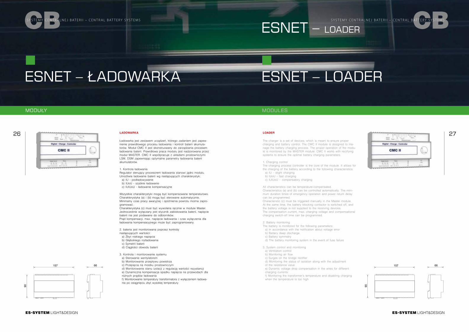
ŁADOWARKA
Ładowarka jest zestawem urządzeń, którego zadaniem jest zapew-nienie prawidłowego procesu ładowania i kontroli baterii akumula-torów. Moduł CMC II jest skonstruowany do zarządzania procesem ładowania baterii. Prawidłowa praca modułu jest nadzorowana przez moduł MASTER. CMC II współpracuje z układami prostowniczymi LSM, DSM zapewniając optymalne parametry ładowania baterii akumulatorów.
1. Kontrola ładowaniaRegulator sterujący procesorem ładowania stanowi jądro modułu. Umożliwia ładowanie baterii wg następujących charakterystyk:a) IU - podładowywanieb) IUoU - szybkie ładowaniec) IUIUoU - ładowanie kompensacyjne
Wszystkie charakterystyki mogą być kompensowane temperaturowo.Charakterystyka (a) i (b) mogą być sterowane automatycznie. Minimalny czas pracy awaryjnej i opóźnienia powrotu można zapro-gramować.Charakterystyka (c) musi być wywołana ręcznie w module Master. Jednocześnie wyłączany jest stycznik zablokowania baterii, napięcie baterii nie jest podawane do odbiorników.Prąd kompensacji, max. napięcie ładowania i czas wyłączenia dla ładowania kompensacyjnego może być zaprogramowany.
2. bateria jest monitorowana poprzez kontrolę następujących wartości:a) Zbyt niskiego napięciab) Głębokiego rozładowaniac) Symetrii bateriid) Ciągłości obwodu baterii
3. Kontrola i monitorowanie systemua) Sterowanie wentylatorem b) Monitorowanie przepływu powietrza c) Przepięcia na mostku prostowniczym d) Monitorowanie stanu izolacji z regulacją wartości rezystancjie) Dynamiczna kompensacja spadku napięcia na przewodach dla różnych prądów ładowania f) Monitorowanie temperatury transformatora z wyłączeniem ładowa-nia po osiągnięciu zbyt wysokiej temperatury
ESNET – LOADER
CBS Y S T E M Y C E N T R A L N E J B AT E R I I – C E N T R A L B AT T E R Y S Y S T E M S
LOADER
The charger is a set of devices, which is meant to ensure proper charging and battery control. The CMC II module is designed to ma-nage the battery charging process. The proper operation of the modu-le is monitored by the MASTER module. CMC II works with rectifying systems to ensure the optimal battery charging parameters.
1. Charging controlThe charging process controller is the core of the module. It allows for the charging of the battery according to the following characteristics:a) IU – slight chargingb) IUoU – fast chargingc) IUIUoU – compensatory charging
All characteristics can be temperature-compensated.Characteristics (a) and (b) can be controlled automatically. The mini-mum duration times of emergency operation and power return delay can be programmed.Characteristic (c) must be triggered manually in the Master module. At the same time, the battery blocking contactor is switched off, and the battery voltage is not supplied to the receiving devices.The compensation current, max. charging voltage and compensational charging switch-off time can be programmed.
2. Battery monitoringThe battery is monitored for the following parameters:a) In accordance with the notification about voltage error b) Battery deep discharge c) Battery symmetry d) The battery monitoring system in the event of fuse failure
3. System control and monitoringa) Ventilation control b) Monitoring air flow c) Surges on the bridge rectifier d) Monitoring the status of isolation along with the adjustment of the resistance value e) Dynamic voltage drop compensation in the wires for different charging currents f) Monitoring the transformer’s temperature and disabling charging when the temperature is too high
ESNET – LOADER90
66157
90
66157
MODUŁY MODULES
LIGHT&DESIGN
28 29
LIGHT&DESIGN
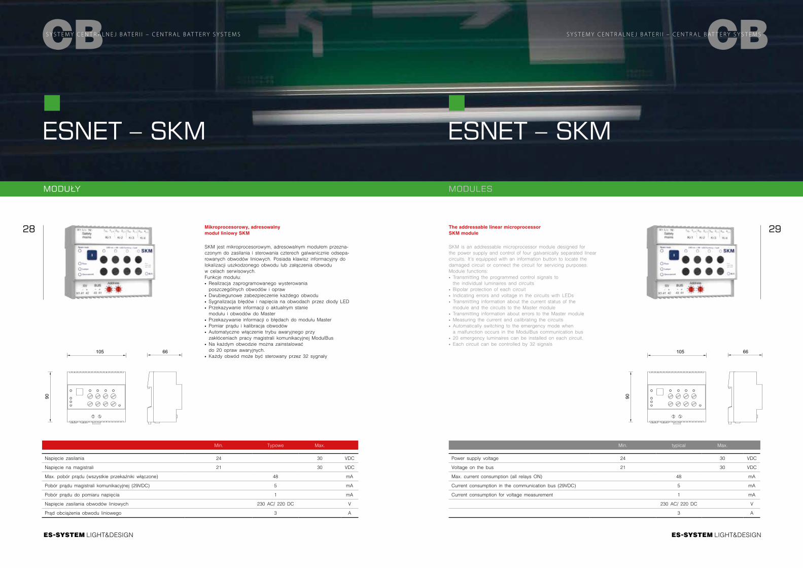
Mikroprocesorowy, adresowalny moduł liniowy SKM
SKM jest mikroprocesorowym, adresowalnym modułem przezna-czonym do zasilania i sterowania czterech galwanicznie odsepa-rowanych obwodów liniowych. Posiada klawisz informacyjny do lokalizacji uszkodzonego obwodu lub załączenia obwodu w celach serwisowych. Funkcje modułu: ∙ Realizacja zaprogramowanego wysterowania poszczególnych obwodów i opraw
∙ Dwubiegunowe zabezpieczenie każdego obwodu ∙ Sygnalizacja błędów i napięcia na obwodach przez diody LED ∙ Przekazywanie informacji o aktualnym stanie modułu i obwodów do Master
∙ Przekazywanie informacji o błędach do modułu Master ∙ Pomiar prądu i kalibracja obwodów ∙ Automatyczne włączenie trybu awaryjnego przy zakłóceniach pracy magistrali komunikacyjnej ModulBus
∙ Na każdym obwodzie można zainstalować do 20 opraw awaryjnych.
∙ Każdy obwód może być sterowany przez 32 sygnały
Min. Typowe Max.
Napięcie zasilania 24 30 VDC
Napięcie na magistrali 21 30 VDC
Max. pobór prądu (wszystkie przekaźniki włączone) 48 mA
Pobór prądu magistrali komunikacyjnej (29VDC) 5 mA
Pobór prądu do pomiaru napięcia 1 mA
Napięcie zasilania obwodów liniowych 230 AC/ 220 DC V
Prąd obciążenia obwodu liniowego 3 A
CBS Y S T E M Y C E N T R A L N E J B AT E R I I – C E N T R A L B AT T E R Y S Y S T E M S
ESNET – SKM
Min. typical Max.
Power supply voltage 24 30 VDC
Voltage on the bus 21 30 VDC
Max. current consumption (all relays ON) 48 mA
Current consumption in the communication bus (29VDC) 5 mA
Current consumption for voltage measurement 1 mA
230 AC/ 220 DC V
3 A
The addressable linear microprocessor SKM module
SKM is an addressable microprocessor module designed for the power supply and control of four galvanically separated linear circuits. It’s equipped with an information button to locate the damaged circuit or connect the circuit for servicing purposes. Module functions: ∙ Transmitting the programmed control signals to the individual luminaires and circuits
∙ Bipolar protection of each circuit ∙ Indicating errors and voltage in the circuits with LEDs ∙ Transmitting information about the current status of the module and the circuits to the Master module
∙ Transmitting information about errors to the Master module ∙ Measuring the current and calibrating the circuits ∙ Automatically switching to the emergency mode when a malfunction occurs in the ModulBus communication bus
∙ 20 emergency luminaires can be installed on each circuit. ∙ Each circuit can be controlled by 32 signals
ESNET – SKM
CBS Y S T E M Y C E N T R A L N E J B AT E R I I – C E N T R A L B AT T E R Y S Y S T E M S
90
66105
90
66105
MODUŁY MODULES
LIGHT&DESIGN
30 31
LIGHT&DESIGN
CBS Y S T E M Y C E N T R A L N E J B AT E R I I – C E N T R A L B AT T E R Y S Y S T E M S
ESNET – IOM24
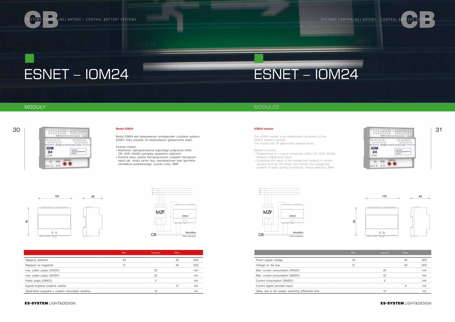
Moduł IOM24
Moduł IOM24 jest adresowalnym podzespołem czujników systemu ESNET, który posiada 16 odizolowanych galwanicznie wejść.
Funkcje modułu: ∙ Możliwość zaprogramowania logicznego połączenia (AND, OR, XOR, NAND) pomiędzy sąsiednimi wejściami
∙ Kontrola stanu styków beznapięciowych urządzeń sterujących takich jak: moduł zaniku fazy, beznapięciowe styki łączników oświetlenia podstawowego, czujniki ruchu, BMS
Min. Typowe Max.
Napięcie zasilania 24 30 VDC
Napięcie na magistrali 21 30 VDC
max. pobór prądu (24VDC) 25 mA
max. pobór prądu (30VDC) 32 mA
Pobór prądu (29VDC) 5 mA
Sygnał prądowy (wejście zwarte) 6 mA
Opóźnienie związane z czasem nieczułości systemu 15 ms
ESNET – IOM24
CBS Y S T E M Y C E N T R A L N E J B AT E R I I – C E N T R A L B AT T E R Y S Y S T E M S
IOM24 module
The IOM24 module is an addressable component of the ESNET system’s sensors.The module has 16 galvanically isolated inputs.
Module functions: ∙ Programming of a logical connection (AND, OR, XOR, NAND) between neighboring inputs
∙ Controlling the status of the voltage-free contacts in control devices such as: the phase loss module, the voltage-free contacts of basic lighting connectors, motion detectors, BMS
Min. typical Max.
Power supply voltage 24 30 VDC
Voltage on the bus 21 30 VDC
Max. current consumption (24VDC) 25 mA
Max. current consumption (30VDC) 32 mA
Current consumption (29VDC) 5 mA
Current signal (shorted input) 6 mA
Delay due to the system switching differential time 15 ms
90
66105
90
66105
MODUŁY MODULES
MZF
L1L2L3N
CBModulBus
YTKSY 2x2x0.8mm ²
IOM24MZF
L1L2L3N
CBModulBus
YTKSY 2x2x0.8mm ²
IOM24
LIGHT&DESIGN
32 33
LIGHT&DESIGN
CBS Y S T E M Y C E N T R A L N E J B AT E R I I – C E N T R A L B AT T E R Y S Y S T E M S
ESNET – IOM230
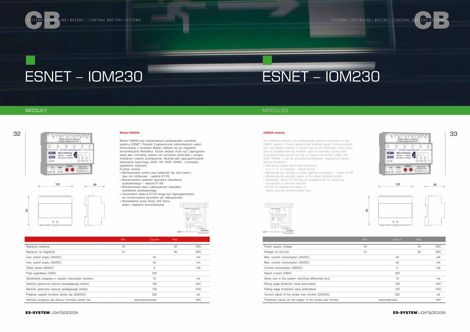
Moduł IOM230
Moduł IOM230 jest adresowalnym podzespołem czujników systemu ESNET. Posiada 9 galwanicznie odizolowanych wejść. Komunikacja z modułem Master odbywa się po magistrali komunikacyjnej ModulBus. Każde wejście może być zaprogramo-wane jako normalnie otwarte lub normalnie zamknięte z progra-mowalnym czasem przełączenia. Możliwe jest zaprogramowanie połączenia logicznego (AND, OR, NOR, NAND…) pomiędzy sąsiednimi wejściami.Funkcje modułu: ∙ Monitorowanie zaniku oraz kolejność faz sieci jedno / dwu lub trójfazowej – wejścia E7-E9
∙ Monitorowanie ustawień łączników oświetlenia podstawowego – wejścia E1-E6
∙ Monitorowanie stanu zabezpieczeń obwodów oświetlenia podstawowego
∙ Opcjonalnie wejścia E7-E9 mogą być zaprogramowane do monitorowania łączników lub zabezpieczeń
∙ Wyświetlanie przez diody LED stanu: wejść, magistrali komunikacyjnej
Min. Typowe Max.
Napięcie zasilania 24 30 VDC
Napięcie na magistrali 21 30 VDC
max. pobór prądu (24VDC) 34 mA
max. pobór prądu (30VDC) 40 mA
Pobór prądu (29VDC) 5 mA
Prąd sygnałowy (230V) 220
Opóźnienie związane z czasem nieczułości systemu 15 ms
Wartość graniczna zbocza narastającego (około) 136 VAC
Wartość graniczna zbocza opadającego (około) 130 VAC
Prądowy sygnał monitora zaniku faz (230VAC) 230 µA
Wartości progowe dla zboczy monitora zaniku faz parametryzowane VAC
ESNET – IOM230
CBS Y S T E M Y C E N T R A L N E J B AT E R I I – C E N T R A L B AT T E R Y S Y S T E M S
IOM230 module
The IOM230 module is an addressable sensor component of the ESNET system. It has 9 galvanically isolated inputs. Communication with the Master module is carried out via the ModulBus. Each input can be programmed as normally open or normally closed, with a programmable switching time. A logical connaction (AND, OR, NOR, NAND…) can be programmed between neighboring inputs.Module functions: ∙ Monitoring phase failure and sequence in a 1-, 2- or 3-phase – inputs E7-E9
∙ Monitoring the settings of basic lighting connectors – inputs E1-E6 ∙ Monitoring the security status of the basic lighting circuits ∙ Optionally, inputs E7-E9 may be programmed for monitoring connectors or security devices
∙ A LED to indicate the statys in: inputs and the communication bus
Min. typical Max.
Power supply voltage 24 30 VDC
Voltage on the bus 21 30 VDC
Max. current consumption (24VDC) 34 mA
Max. current consumption (30VDC) 40 mA
Current consumption (29VDC) 5 mA
Signal current (230V) 220
Delay due to the system switching differential time 15 ms
Rising edge threshold value (estimated) 136 VAC
Falling edge threshold value (estimated) 130 VAC
Current signal of the phase loss monitor (230VAC) 230 µA
Threshold values for the edges of the phase loss monitor parameterized VAC
90
66105
90
66105Ustawienia adresu
Oprawa awaryjna
Oprawy oświetlenia podstawowego
Oświetlenie podstawowe
ModulBus
YTKSY 2x2x0,8 mm2
Ustawienia adresu
Oprawa awaryjna
Oprawy oświetlenia podstawowego
General lighting
ModulBus
YTKSY 2x2x0,8 mm2
MODUŁY MODULES
LIGHT&DESIGN
34 35
LIGHT&DESIGN
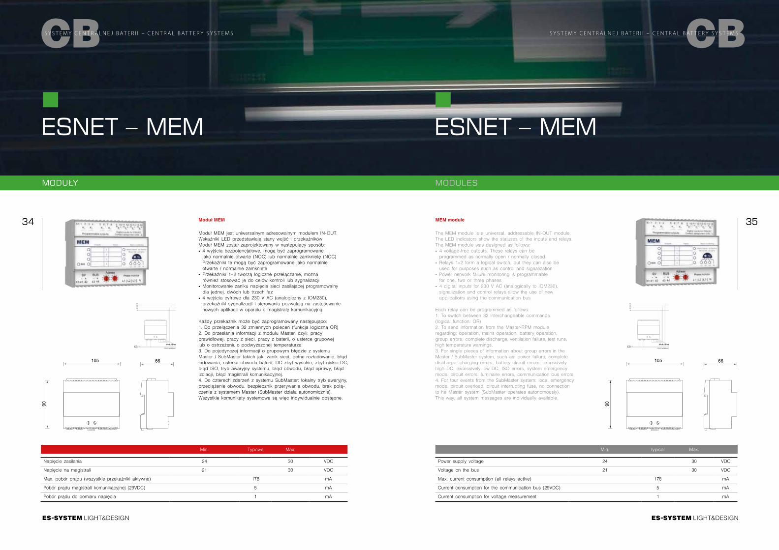
Moduł MEM
Moduł MEM jest uniwersalnym adresowalnym modułem IN-OUT. Wskaźniki LED przedstawiają stany wejść i przekaźnikówModuł MEM został zaprojektowany w następujący sposób: ∙ 4 wyjścia bezpotencjałowe, mogą być zaprogramowane jako normalnie otwarte (NOC) lub normalnie zamknietę (NCC) Przekaźniki te mogą być zaprogramowane jako normalnie otwarte / normalnie zamknięte
∙ Przekaźniki 1+2 tworzą logiczne przełączanie, można również stosować je do celów kontroli lub sygnalizacji
∙ Monitorowanie zaniku napięcia sieci zasilającej programowalny dla jednej, dwóch lub trzech faz
∙ 4 wejścia cyfrowe dla 230 V AC (analogiczny z IOM230), przekaźniki sygnalizacji i sterowania pozwalają na zastosowanie nowych aplikacji w oparciu o magistralę komunikacyjną
Każdy przekaźnik może być zaprogramowany następująco:1. Do przełączenia 32 zmiennych poleceń (funkcja logiczna OR)2. Do przesłania informacji z modułu Master, czyli: pracy prawidłowej, pracy z sieci, pracy z baterii, o usterce grupowej lub o ostrzeżeniu o podwyższonej temperaturze.3. Do pojedynczej informacji o grupowym błędzie z systemu Master / SubMaster takich jak: zanik sieci, pełne rozładowanie, błąd ładowania, usterka obwodu baterii, DC zbyt wysokie, zbyt niskie DC, błąd ISO, tryb awaryjny systemu, błąd obwodu, błąd oprawy, błąd izolacji, błąd magistrali komunikacyjnej.4. Do czterech zdarzeń z systemu SubMaster: lokalny tryb awaryjny, przeciążenie obwodu, bezpiecznik przerywania obwodu, brak połą-czenia z systemem Master (SubMaster działa autonomicznie).Wszystkie komunikaty systemowe są więc indywidualnie dostępne.
Min. Typowe Max.
Napięcie zasilania 24 30 VDC
Napięcie na magistrali 21 30 VDC
Max. pobór prądu (wszystkie przekaźniki aktywne) 178 mA
Pobór prądu magistrali komunikacyjnej (29VDC) 5 mA
Pobór prądu do pomiaru napięcia 1 mA
CBS Y S T E M Y C E N T R A L N E J B AT E R I I – C E N T R A L B AT T E R Y S Y S T E M S
ESNET – MEM
Min. typical Max.
Power supply voltage 24 30 VDC
Voltage on the bus 21 30 VDC
Max. current consumption (all relays active) 178 mA
Current consumption for the communication bus (29VDC) 5 mA
Current consumption for voltage measurement 1 mA
ESNET – MEM
CBS Y S T E M Y C E N T R A L N E J B AT E R I I – C E N T R A L B AT T E R Y S Y S T E M S
MEM module
The MEM module is a universal, addressable IN-OUT module. The LED indicators show the statuses of the inputs and relays.The MEM module was designed as follows: ∙ 4 voltage-free outputs. These relays can be programmed as normally open / normally closed
∙ Relays 1+2 form a logical switch, but they can also be used for purposes such as control and signalization
∙ Power network failure monitoring is programmable for one, two or three phases
∙ 4 digital inputs for 230 V AC (analogically to IOM230), signalization and control relays allow the use of new applications using the communication bus
Each relay can be programmed as follows:1. To switch between 32 interchangeable commands (logical function: OR)2. To send information from the Master-RPM module regarding: operation, mains operation, battery operation, group errors, complete discharge, ventilation failure, test runs, high temperature warnings.3. For single pieces of information about group errors in the Master / SubMaster system, such as: power failure, complete discharge, charging errors, battery circuit errors, excessively high DC, excessively low DC, ISO errors, system emergency mode, circuit errors, luminaire errors, communication bus errors.4. For four events from the SubMaster system: local emergency mode, circuit overload, circuit interrupting fuse, no connection to he Master system (SubMaster operates autonomously).This way, all system messages are individually available.
90
66105
90
66105
MODUŁY MODULES
Modul BusYTKSY 2x2x0.8mm ²
L1L2L3N
CBModul Bus
YTKSY 2x2x0.8mm ²
L1L2L3N
CB
LIGHT&DESIGN
36 37
LIGHT&DESIGN
CBS Y S T E M Y C E N T R A L N E J B AT E R I I – C E N T R A L B AT T E R Y S Y S T E M S
ESNET – WEB
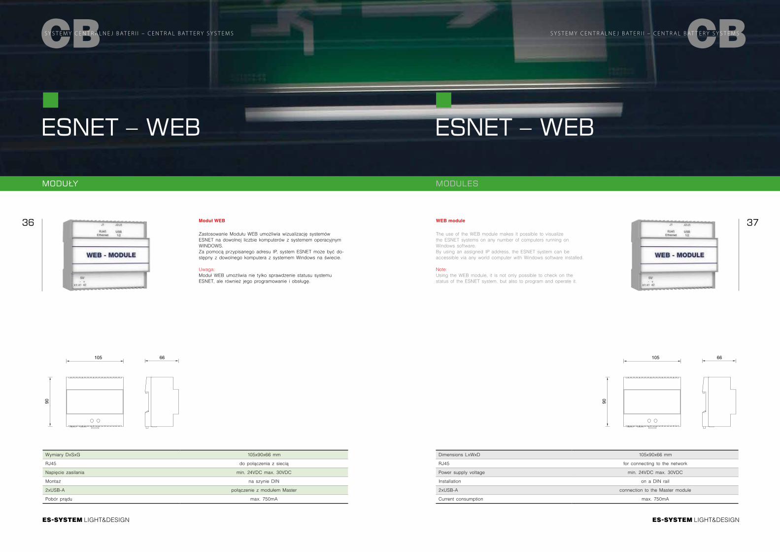
Moduł WEB
Zastosowanie Modułu WEB umożliwia wizualizację systemów ESNET na dowolnej liczbie komputerów z systemem operacyjnym WINDOWS.Za pomocą przypisanego adresu IP, system ESNET może być do-stępny z dowolnego komputera z systemem Windows na świecie.
Uwaga:Moduł WEB umożliwia nie tylko sprawdzenie statusu systemu ESNET, ale również jego programowanie i obsługę.
Wymiary DxSxG 105x90x66 mm
RJ45 do połączenia z siecią
Napięcie zasilania min. 24VDC max. 30VDC
Montaż na szynie DIN
2xUSB-A połączenie z modułem Master
Pobór prądu max. 750mA
ESNET – WEB
CBS Y S T E M Y C E N T R A L N E J B AT E R I I – C E N T R A L B AT T E R Y S Y S T E M S
WEB module
The use of the WEB module makes it possible to visualize the ESNET systems on any number of computers running on Windows software.By using an assigned IP address, the ESNET system can be accessible via any world computer with Windows software installed.
Note:Using the WEB module, it is not only possible to check on the status of the ESNET system, but also to program and operate it.
Dimensions LxWxD 105x90x66 mm
RJ45 for connecting to the network
Power supply voltage min. 24VDC max. 30VDC
Installation on a DIN rail
2xUSB-A connection to the Master module
Current consumption max. 750mA
90
66105
90
66105
MODUŁY MODULES
LIGHT&DESIGN
38 39
LIGHT&DESIGN
CBS Y S T E M Y C E N T R A L N E J B AT E R I I – C E N T R A L B AT T E R Y S Y S T E M S
ESNET – KNXGateway
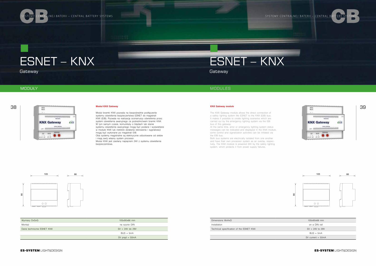
Moduł KNX Gateway
Moduł bramki KNX pozwala na bezpośrednie podłączenie systemu oświetlenia bezpieczeństwa ESNET do magistrali KNX (EIB). Pozwala na realizację scenariuszy oświetlenia przez system oświetlenia awaryjnego za pośrednictwem bramki KNX. W tym samym czasie, komunikaty o błędach lub stanie systemu oświetlenia awaryjnego mogą być podane i wyświetlane w module KNX lub niektóre działania sterowania i sygnalizacji mogą być wykonane po magistrali EIB.Oba systemy magistralne są elektrycznie odizolowane od siebie i mają swój własny system procesor.Moduł KNX jest zasilany napięciem 24V z systemu oświetlenia bezpieczeństwa.
Wymiary DxSxG 105x90x66 mm
Montaż na szynie DIN
Dane techniczne ESNET KNX SV = 24V do 29V
BUS = 5mA
SV prąd = 50mA
ESNET – KNXGateway
CBS Y S T E M Y C E N T R A L N E J B AT E R I I – C E N T R A L B AT T E R Y S Y S T E M S
KNX Gateway module
The KNX Gateway module allows the direct connection of a safety lighting system like ESNET to the KNX (EIB) bus. It makes it possible to create lighting scenarios which are carried out by the emergency lighting system via the EBI bus of this gateway.At the same time, error or emergency lighting system status messages can be indicated and displayed in the KNX module, some control and signalization activities can be initiated via the EIB bus.Both bus systems are electrically isolated from one another and have their own processor system as an overlay, respec-tvely. The KNX module is powered 24V by the safety lighting system, which protects it from power supply failures.
Dimensions WxHxD 105x90x66 mm
Installation on a DIN rail
Technical specification of the ESNET KNX SV = 24V to 29V
BUS = 5mA
SV current = 50mA
90
66105
90
66105
MODUŁY MODULES
LIGHT&DESIGN
40 41
LIGHT&DESIGN
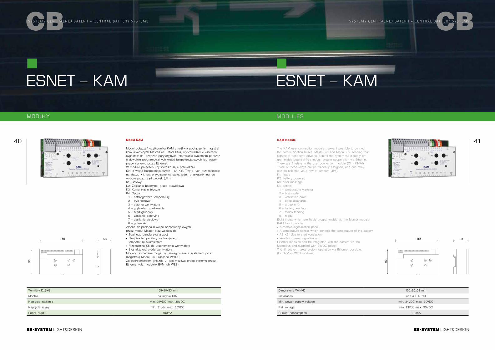
Moduł KAM
Moduł połączeń użytkownika KAM umożliwia podłączenie magistral komunikacyjnych MasterBus i ModulBus, wyprowadzenie czterech sygnałów do urządzeń peryferyjnych, sterowanie systemem poprzez 8 dowolnie programowalnych wejść bezpotencjałowych lub współ-pracę systemu przez Ethernet.W module połączeń użytkownika są 4 przekaźniki (X1: 8 wejść bezpotencjałowych – K1-K4). Trzy z tych przekaźników na złączu X1, jest przypisane na stałe, jeden przekaźnik jest do wyboru przez rząd zworek (JP1).K1: GotowyK2: Zasilanie bateryjne, praca prawidłowaK3: Komunikat o błędzieK4: Opcja: 1 – ostrzegawcza temperatury2 – tryb testowy 3 – usterka wentylatora4 – głębokie rozładowanie5 – błąd grupowy6 – zasilanie bateryjne7 – zasilanie sieciowe8 – gotowość
Złącze X2 posiada 8 wejść bezpotencjałowych przez moduł Master oraz wejścia do: ∙ Zdalnego panelu sygnalizacji ∙ Czujnika temperatury kontrolującego temperaturę akumulatora
∙ Przekaźnika K5 do uruchomienia wentylatora ∙ Sygnalizatora błędu wentylatora Moduły zewnętrzne mogą być zintegrowane z systemem przez magistralę ModulBus i zasilane 24VDC.Za pośrednictwem gniazda J1 jest możliwa praca systemu przez Ethernet (dla modułów BVM lub WEB).
Wymiary DxSxG 155x90x53 mm
Montaż na szynie DIN
Napięcie zasilania min. 24VDC max. 30VDC
Napięcie szyny min. 21Vdc max. 30VDC
Pobór prądu 100mA
CBS Y S T E M Y C E N T R A L N E J B AT E R I I – C E N T R A L B AT T E R Y S Y S T E M S
ESNET – KAM
KAM module
The KAM user connection module makes it possible to connect the communication buses: MasterBus and ModulBus, sending four signals to peripheral devices, control the system via 8 freely pro-grammable potential-free inputs, system cooperation via EthernetThere are 4 relays in the user connection module (X1 - K1-K4)Three of these relays are permanently assigned, and one relay can be selected via a row of jumpers (JP1).K1: readyK2: battery powered K3: error messageK4: option: 1 – temperature warning2 – test mode 3 – ventilation error:4 – deep discharge5 – group error6 – battery feeding7 – mains feeding8 – ready
Eight inputs which are freely programmable via the Master module.KAM has inputs for: ∙ A remote signalization panel ∙ A temperature sensor which controls the temperature of the battery ∙ AS K5 relay to start ventilation ∙ Ventilation error signalization External modules can be integrated with the sustem via the ModulBus and supplied with 24VDC power.The J1 socket makes system operation via Ethernet possible. (for BVM or WEB modules)
Dimensions WxHxD 155x90x53 mm
Installation non a DIN rail
Min. power supply voltage min. 24VDC max. 30VDC
Rail voltage min. 21Vdc max. 30VDC
Current consumption 100mA
ESNET – KAM
CBS Y S T E M Y C E N T R A L N E J B AT E R I I – C E N T R A L B AT T E R Y S Y S T E M S
90
53155
90
53155
MODUŁY MODULES
LIGHT&DESIGN
42 43
LIGHT&DESIGN
CBS Y S T E M Y C E N T R A L N E J B AT E R I I – C E N T R A L B AT T E R Y S Y S T E M S
MODUŁY
ESNET – DNU
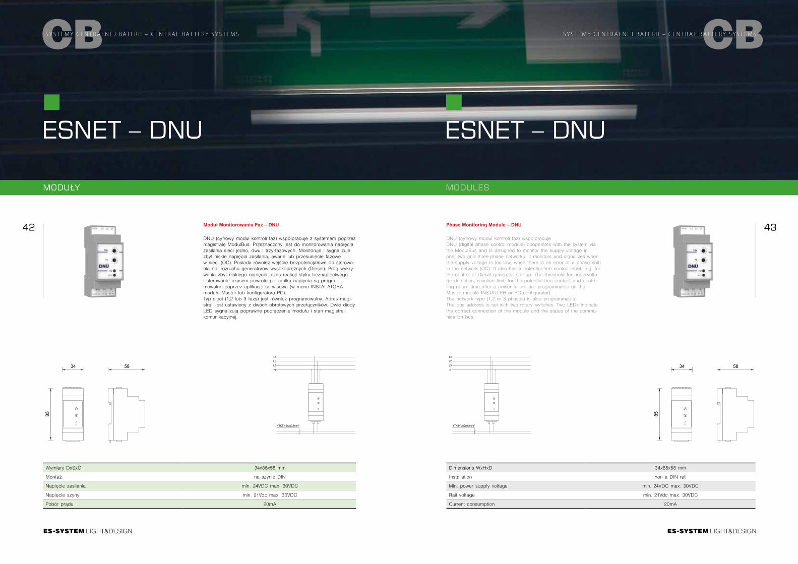
Moduł Monitorowania Faz – DNU
DNU (cyfrowy moduł kontroli faz) współpracuje z systemem poprzez magistralę ModulBus. Przeznaczony jest do monitorowania napięcia zasilania sieci jedno, dwu i trzy-fazowych. Monitoruje i sygnalizuje zbyt niskie napięcia zasilania, awarię lub przesunięcie fazowe w sieci (OC). Posiada również wejście bezpotencjałowe do sterowa-nia np. rozruchu generatorów wysokoprężnych (Diesel). Próg wykry-wania zbyt niskiego napięcia, czas reakcji styku beznapięciwego i sterowanie czasem powrotu po zaniku napięcia są progra- mowalne poprzez aplikację serwisową (w menu INSTALATORA modułu Master lub konfiguratora PC). Typ sieci (1,2 lub 3 fazy) jest również programowalny. Adres magi-strali jest ustawiony z dwóch obrotowych przełączników. Dwie diody LED sygnalizują poprawne podłączenie modułu i stan magistrali komunikacyjnej.
Wymiary DxSxG 34x85x58 mm
Montaż na szynie DIN
Napięcie zasilania min. 24VDC max. 30VDC
Napięcie szyny min. 21Vdc max. 30VDC
Pobór prądu 20mA
MODULES
ESNET – DNU
CBS Y S T E M Y C E N T R A L N E J B AT E R I I – C E N T R A L B AT T E R Y S Y S T E M S
Phase Monitoring Module – DNU
DNU (cyfrowy moduł kontroli faz) współpracuje DNU (digital phase control module) cooperates with the system via the ModulBus and is designed to monitor the supply voltage in one, two and three-phase networks. It monitors and signalizes when the supply voltage is too low, when there is an error or a phase shift in the network (OC). It also has a potential-free control input, e.g. for the control of Diesel generator startup. The threshold for undervolta-ge detection, reaction time for the potential-free contact and control-ling return time after a power failure are programmable (in the Master module INSTALLER or PC configurator). The network type (1,2 or 3 phases) is also programmable. The bus address is set with two rotary switches. Two LEDs indicate the correct connection of the module and the status of the commu-nication bus.
Dimensions WxHxD 34x85x58 mm
Installation non a DIN rail
Min. power supply voltage min. 24VDC max. 30VDC
Rail voltage min. 21Vdc max. 30VDC
Current consumption 20mA
85
5834
85
5834
L1L2L3N
YTKSY 2x2x0.8mm²
L1L2L3N
YTKSY 2x2x0.8mm²
LIGHT&DESIGN
44 45
LIGHT&DESIGN
CBS Y S T E M Y C E N T R A L N E J B AT E R I I – C E N T R A L B AT T E R Y S Y S T E M S
MODUŁY MODULES
ESNET – MSU3
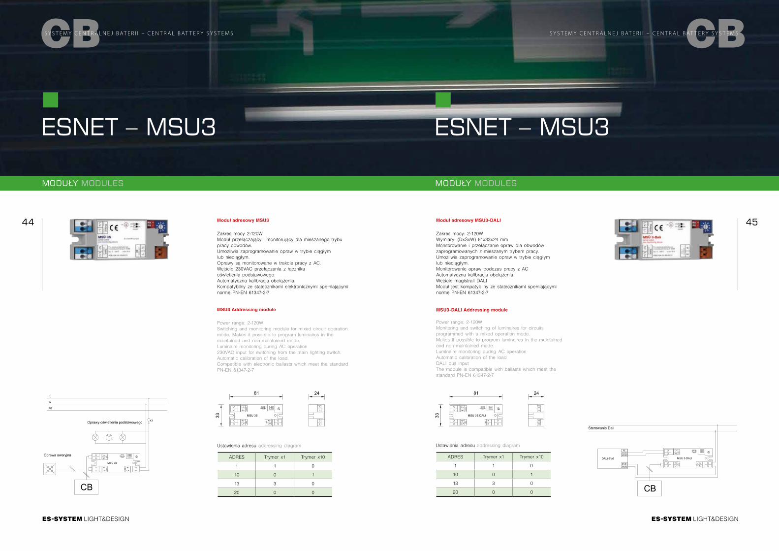
Moduł adresowy MSU3
Zakres mocy 2-120WModuł przełączający i monitorujący dla mieszanego trybu pracy obwodów. Umożliwia zaprogramowanie opraw w trybie ciągłym lub nieciągłym.Oprawy są monitorowane w trakcie pracy z AC.Wejście 230VAC przełączania z łącznika oświetlenia podstawowego.Automatyczna kalibracja obciążenia.Kompatybilny ze statecznikami elektronicznymi spełniającymi normę PN-EN 61347-2-7
MSU3 Addressing module
Power range: 2-120WSwitching and monitoring module for mixed circuit operation mode. Makes it possible to program luminaires in the maintained and non-maintained mode.Luminaire monitoring during AC operation230VAC input for switching from the main lighting switch.Automatic calibration of the load.Compatible with electronic ballasts which meet the standard PN-EN 61347-2-7
MODUŁY MODULES
ESNET – MSU3
CBS Y S T E M Y C E N T R A L N E J B AT E R I I – C E N T R A L B AT T E R Y S Y S T E M S
Moduł adresowy MSU3-DALI
Zakres mocy: 2-120WWymiary: (DxSxW) 81x33x24 mmMonitorowanie i przełączanie opraw dla obwodów zaprogramowanych z mieszanym trybem pracy.Umożliwia zaprogramowanie opraw w trybie ciągłym lub nieciągłym.Monitorowanie opraw podczas pracy z ACAutomatyczna kalibracja obciążeniaWejście magistrali DALIModuł jest kompatybilny ze statecznikami spełniającymi normę PN-EN 61347-2-7
MSU3-DALI Addressing module
Power range: 2-120WMonitoring and switching of luminaires for circuits programmed with a mixed operation mode. Makes it possible to program luminaires in the maintained and non-maintained mode.Luminaire monitoring during AC operationAutomatic calibration of the loadDALI bus inputThe module is compatible with ballasts which meet the standard PN-EN 61347-2-7
ADRES Trymer x1 Trymer x10
1 1 0
10 0 1
13 3 0
20 0 0
Ustawienia adresu addressing diagram
ADRES Trymer x1 Trymer x10
1 1 0
10 0 1
13 3 0
20 0 0
Ustawienia adresu addressing diagram
N/-L/+ output
MSU 3S DALI
+10
DS BS
0
0+0=20
N/-L/+
input
AEDA
LI
81
33
24
DALI-EVG
CB
PEAC/DCAC/DC
DA/D1DA/D2
Sterowanie Dali
L
N
Oprawy oświetlenia podstawowego
N/-L/+ input
MSU 3S
CB
Oprawa awaryjna +10
DS BS
0
0+0=20
PE
K1
N/-L/+
output
N/-L/+
input
N/-L/+ output
MSU 3-DALI
+10
DS BS
0
0+0=20
N/-L/+
input
AEDA
LI
DALI-EVG
CB
PEAC/DCAC/DC
DA/D1DA/D2
Sterowanie Dali
L
N
Oprawy oświetlenia podstawowego
N/-L/+ input
MSU 3S
CB
Oprawa awaryjna +10
DS BS
0
0+0=20
PE
K1
N/-L/+
output
N/-L/+
input
N/-L/+ output
MSU 3-DALI
+10
DS BS
0
0+0=20
N/-L/+
input
AEDA
LI
N/-L/+ output
MSU 3S
+10
DS BS
0
0+0=20
N/-L/+
input
81
33
24
N/-L/+inp
ut
LIGHT&DESIGN
47
LIGHT&DESIGN
46
CBS Y S T E M Y C E N T R A L N E J B AT E R I I – C E N T R A L B AT T E R Y S Y S T E M S CBS Y S T E M Y C E N T R A L N E J B AT E R I I – C E N T R A L B AT T E R Y S Y S T E M S
LIGHT&DESIGN LIGHT&DESIGN
LIGHT&DESIGN
48 49
LIGHT&DESIGN
NORMY I PRZEPISY
Systemy i oprawy oświetlenia awaryjnego opracowano zgodnie z europejskimi normami EN 1838:1999 oraz EN 60 598-2-22:1998.Normy wspólnotowe stanowią standard techniczny - podstawowe wytyczne dotyczące oświetlenia awaryjnego. Dokładne regulacje precyzowane są oddzielnie dla każdego z państw członkowskich.
Instalacja awaryjnego oświetlenia ewakuacyjnego powinna: ∙ oświetlać znaki drogi ewakuacyjnej ∙ zapewniać natężenie oświetlenia na drogach ewakuacyjnych, by ruch w kierunku wyjścia ewakuacyjnego z obiektu był bezpieczny ∙ zapewniać łatwe zlokalizowanie i użycie przycisków alarmu pożarowego i sprzętu przeciwpożarowego rozmieszczonego wzdłuż dróg ewakuacyjnych
∙ umożliwiać działanie związane ze środkami bezpieczeństwa
Zasady projektowania
A. Podział oświetlenia awaryjnego.
1. Oświetlenie ewakuacyjne zapewniające bezpieczną ewakuację w czasie zaniku zasilania oświetlenia podstawowego
Oświetlenie drogi ewakuacyjnej. Oświetlenie drogi ewakuacyjnej ma umożliwić skuteczne rozpoznanie i bezpieczne użytkowanie środków ewa-kuacji i urządzeń przeciwpożarowych przez osoby opuszczające miejsce przebywania. Droga ewakuacyjna używana w przypadku wystąpienia zagrożenia zaczyna się w miejscu startu ewakuacji, a kończy się w miejscu bezpiecznym, czyli miejscu zaprojektowanym, gdzie ewakuujący się ludzie mogą się zebrać i przebywać bezpiecznie nie będąc narażonym na niebezpieczeństwo. Stosowanie oświetlenia awaryjnego w postaci znaków bezpieczeństwa na drodze ewakuacyjnej ma na celu zapewnienie prawidłowych warunków wizualnych oraz możliwości identyfikacji kierunku ewakuacji w celu szybkiej lokalizacji i użycia drogi ewakuacyjnej. Na drogach ewakuacyjnych o szerokości do 2 m natężenie oświetlenia na podłodze wzdłuż osi drogi ewakuacyjnej nie może być mniejsze niż 1lx. Część drogi ewakuacyjnej stanowiącej nie mniej niż połowę szerokości drogi powinna być oświetlona z natężeniem co najmniej 50% tej wartości.
Oświetlenie przestrzeni otwartej. Oświetlenie to jest stosowane w strefach o nieokreślonych drogach ewakuacyjnych w halach lub w obiektach o powierzchni podłogi większej niż 60 m2 lub w mniejszych, jeżeli istnieje dodatkowe zagrożenie wywołane obecnością dużej liczby osób. Definicję strefy uzupełniono przestrzenią toalety dla osób niepełnosprawnych – tak zdefiniowane toalety wymagają oświetlenia jak dla strefy otwartej. Celem oświetlenia strefy otwartej jest zmniejszenie prawdopodobieństwa paniki i umożliwienie bezpiecznego ruchu osób w kierunku dróg ewakuacyjnych, poprzez stworzenie odpowiednich warunków wizualnych w odnajdowaniu kierunku ewakuacji.Natężenie oświetlenia w tej strefie nie powinno być mniejsze niż 0,5 lx na całej powierzchni poziomej strefy. Nie uwzględnia się marginesu obszary o szerokości 0,5 m.
Oświetlenie strefy wysokiego ryzyka. Zadaniem oświetlenia ewakuacyjnego stref wysokiego ryzyka jest zapewnienie bezpieczeństwa ludziom zaangażowanym w potencjalnie niebezpieczny proces lub sytuację i umożliwienie im właściwego zakończenia procedur. Natężenie oświetlenia na płaszczyźnie odniesienia w strefie wysokiego ryzyka nie może być mniejsze niż 10% natężenia oświetlenia podstawowego lecz nie mniej niż 15lx. Czas podtrzymania powinien być dłuższy od czasu trwania zagrożenia.
2. Oświetlenie zapasowe jest częścią oświetlenia awaryjnego umożliwiająca kontynuowanie normalnych czynności w sposób zasadniczo niezmienny.
B. Zalecenia dla rozmieszczenia opraw oświetlenia awaryjnego. Oprawy powinny być umieszczane: ∙ przy każdych drzwiach wyjściowych przeznaczonych do wyjścia ewakuacyjnego ∙ w pobliżu schodów, tak by każdy stopień był oświetlony bezpośrednio
S Y S T E M Y C E N T R A L N E J B AT E R I I – C E N T R A L B AT T E R Y S Y S T E M SESNET
CB
ESNET ∙ w pobliżu każdej zmiany poziomu ∙ przy wyjściach ewakuacyjnych i znakach bezpieczeństwa ∙ przy każdej zmianie kierunku ∙ przy każdym skrzyżowaniu korytarzy ∙ na zewnątrz, w pobliżu każdego wyjścia końcowego, aż do miejsca bezpiecznego ∙ w pobliżu każdego punktu pierwszej pomocy ∙ w pobliżu każdego urządzenia przeciwpożarowego i przycisku alarmowego ∙ w pobliżu urządzeń przewidzianych do ewakuacyjnych dla osób niepełnosprawnych ∙ w pobliżu stref dla osób niepełnosprawnych i punktu przywoławczego. Zalicza się do nich strefy z systemami komunikacji dwukierunkowej, toalety dla osób niepełnosprawnych z urządzeniami przywoławczymi.
C. Rozpoznawalność znaku ewakuacyjnego.Rozpoznawalność znaku „d” określona wzorem d = s*p, jest zależna od wysokości piktogramu „p” oraz typu zastosowanego znaku kierunko-wego współczynnik s = 100 przyjmowany jest dla znaków oświetlanych z zewnątrz natomiast s = 200 dla znaków podświetlanych od wewnątrz.
D. Podstawowe czynności z zakresu kontrolowania stanu oświetlenia awaryjnego.ROZPORZADZENIE MINISTRA SPRAW WEWNĘTRZNYCH I ADMINISTRACJI z dn. 7 czerwca 2010 roku nakazuje by przeglądy techniczne i czynności konserwacyjne urządzeń przeciwpożarowych były przeprowadzane w okresach wyznaczonych przez producenta, lecz nie rzadziej jednak niż raz w roku.Zgodnie z normą PN-EN 50172 rysunki wykonawcze zrealizowanej instalacji awaryjnego oświetlenia ewakuacyjnego należy dostarczy i prze-chowywać w obrębie nieruchomości. Na rysunkach powinny być wymienione wszystkie oprawy i podstawowe komponenty. Dane te należy aktualizować stosownie do kolejnych zmian w systemie. Rysunki powinny być podpisane przez kompetentną osobę weryfikującą projekt pod kątem wymagań zawartych w niniejszej normie.
Dodatkowo należy prowadzić dziennik w celu zapisywania rutynowych sprawozdań, testów, uszkodzeń i zmian.Dziennik taki musi zawierać: ∙ daty zamówienia systemów oświetlenia awaryjnego; ∙ daty wszystkich wykonywanych testów i konserwacji; ∙ data i zwięzły opis każdego serwisu, sprawdzenia; ∙ data i zwięźle opisane szczegóły każdego uszkodzenia oraz przeprowadzonych napraw ∙ data i zwięzły opisz wszelkich zmian w systemie oświetlenia awaryjnego ∙ opis charakterystyki i sposób działania systemów automatycznego testowania.
Testowanie urządzeń oświetlenia awaryjnego- testy okresowe wskazane w normie PN-EN 50172. ∙ Test codzienny – Inspekcja polega na wzrokowym sprawdzeniu wskaźników systemu, a ma na celu rozpoznanie sta-nu gotowości systemu centralnego zasilania do pracy oraz czy system nie wymaga przeprowadzenia testu.
∙ Test comiesięczny – test comiesięczny polega na sprawdzeniu systemu oświetlenia awaryjnego po względem funkcjonalności tzn. po-przez symulację uszkodzenia zasilania podstawowego na czas wystarczający by sprawdzić, czy wszystkie przewidziane oprawy ewaku-acyjne i znaki bezpieczeństwa przełączyły się do pracy awaryjnej oraz powróciły do normalnej pracy po powrocie zasilania sieciowego.
∙ jeżeli stosowane są automatyczne urządzenia testujące, to wyniki krótkotrwałych testów należy rejestrować. ∙ Test roczny - test coroczny polega na sprawdzeniu funkcjonalności i czasu podtrzymania systemu oświetlenia awaryjnego tzn. poprzez symulację uszkodzenia zasilania podstawowego, należy sprawdzić, czy wszystkie przewidziane oprawy ewakuacyjne i znaki bezpieczeństwa przełączyły się do pracy awaryjnej oraz po powrocie zasilania sieciowego powróciły do normalnej pracy.
Czas trwania testu powinien być wystarczający do sprawdzenia przewidzianej autonomii podtrzymania oświetlenia awaryjnego zgodnie z informacją producenta. W trakcie testu należy sprawdzić każdą lampkę kontrolną lub urządzenie, upewniając się, że wskazania są prawi-dłowe. Zaleca się sprawdzenie poprawności działania układu ładowania. Jeżeli stosowane są automatyczne urządzenia testujące, to wyniki pełnych znamionowych testów czasu trwania należy rejestrować.
E. Rozporządzenia i normy dotyczące oświetlenia awaryjnego:
LIGHT&DESIGN
50 51
LIGHT&DESIGN
1. Rozporządzenie Ministra Infrastruktury z dnia 12 kwietnia 2002 r. w sprawie warunków technicznych, jakim powinny odpowiadać budynki i ich usytuowanie. Rozporządzenie Ministra Infrastruktury z dnia 12 kwietnia 2002r. Dz. U. 75 poz. 690 z późniejszymi zmianami - Rozpo-rządzenie Ministra Infrastruktury z dnia 12 marca 2009r Dz.U. Nr 56 poz. 461 oraz Rozporządzenie Ministra Infrastruktury z dnia 10 grudnia 2010r. Dz.U. Nr 239 poz. 1597.
2. Rozporządzenie Ministra Spraw Wewnętrznych i Administracji z dnia 20 czerwca 2007 r.w sprawie wykazu wyrobów służących zapewnieniu bezpieczeństwa publicznego lub ochronie zdrowia i życia oraz mienia, a także zasad wydawania dopuszczenia tych wyrobów do użytkowania (Dz.U. 143 poz. 1002).
3. Rozporządzenie Ministra Spraw Wewnętrznych i Administracji z dnia 7 czerwca 2010 r. w sprawie ochrony przeciwpożarowej budynków, innych obiektów budowlanych i terenów (Dz. U. Nr 109 poz. 719).
4. Rozporządzenie Ministra Spraw Wewnętrznych i Administracji z dnia 27 kwietnia 2010 r. w sprawiewykazu wyrobów służących zapewnieniu bezpieczeństwa publicznego lub ochronie zdrowia i życiaoraz mienia, a także zasad wydawania dopuszczenia tych wyrobów do użytku (Dz. U. Nr 85 poz. 553).
5. PN EN 50172 Systemy awaryjnego oświetlenia ewakuacyjnego.
6. PN EN 1838:2013 Zastosowania oświetlenia. Oświetlenie awaryjne.
7. Wytycznych MLAR - (wzorcowe wytyczne konferencji ministrów budownictwa odnośnie wymagań dotyczących technicznych aspektów ochro-ny przeciwpożarowej instalacji elektrycznych) uwzględniającej wymagania Parlamentu Europejskiego zawartych w wytycznych 98/24/EG rady z dnia 11.06.1998 zmienione poprzez wytyczne 98/48/EG z dnia 20.07.1998 (Abl. EG Nr. L 217 S.18).
Dodatkowo w trakcie projektowania należy stosować zapisy następujących norm: ∙ PN-EN 60598-2-22:2004/AC Oprawy oświetleniowe- Część 2-22: Wymagania szczegółowe – Oprawy oświetleniowe do oświetlenia awaryjnego
∙ PN-EN 50171:2007: Centralne systemy zasilania ∙ PN-EN 50272-2:2007: Wymagania bezpieczeństwa i instalowania baterii wtórnych - Część 2: Baterie stacjonarne ∙ PN-92/N-01256/02:1992 Znaki bezpieczeństwa - Ewakuacja ∙ HD 384/HD 60364 PN-IEC 60364:1999 (norma wieloczęściowa) Instalacje elektryczne w obiektach budowlanych ∙ PN-EN 12464-1:2004 Światło i oświetlenie - Oświetlenie miejsc pracy - Część 1: Miejsca pracy we wnętrzach ∙ PN-EN 60529:2003 Stopnie ochrony zapewnianej przez obudowy (Kod IP) ∙ PN-EN 61347:2005 (norma wieloczęściowa) Urządzenia do lamp - Część 2-7: Wymagania szczegółowe dotyczące stateczników elektronicznych zasilanych prądem stałym, do oświetlenia awaryjnego
∙ PN-N-01256-5:1998 Znaki bezpieczeństwa. Zasady umieszczania znaków bezpieczeństwa na drogach ewakuacyjnych i drogach pożarowych
∙ PN-N-01255:1992 Barwy bezpieczeństwa i znaki bezpieczeństwa
S Y S T E M Y C E N T R A L N E J B AT E R I I – C E N T R A L B AT T E R Y S Y S T E M SESNET
CB
ESNET STANDARDS AND REGULATIONS
Our emergency lighting systems and emergency luminaires have been designed and manufactured in accordance with the European Stan-dards EN 1838:1999 and EN 60 598-2-22:1998.The EU norms are a technical standard – they are the basic guidelines for emergency lighting. The exact regulations are defined separately for each of the Member States. The primary standards applicable in the selected countries can be found on the neighboring page.
An emergency escape lighting installation should fulfill the following functions: ∙ illuminating escape route signs ∙ producing a certain level of light intensity on the escape routes in order to maintain safety during evacuation in the direction of the escape exit ∙ making it easy to locate and make use of fire alarm buttons and fire extinguishing equipment arranged along the escape routes ∙ making it possible to perform security measures
Designing principles
A. Types of emergency lighting
1. Emergency escape lighting to allow safe evacuation during a power outage when the basic lighting is turned off
Lighting escape routes. Escape route lighting should allow escaping persons to effectively identify and safely make use of the means of escape and fire safety equipment. The escape route used in the event of an emergency begins at the starting point of the evacuation and ends at a safety point, which is a location designated for the gathering of evacuating persons, where they can stay safely, without being exposed to danger. The use of emergency lighting in the form or safety signs along the escape route is designed to ensure the correct visual conditions and the possibility to identify the direction of escape in order to quickly locate and make use of the escape route.An illuminance of 1 lux is required in the axis of the 2 m-wide escape route, and it may not reach a value lesser than 0.5 lux within the distance of 1 m from the axis.
Lighting of general access zones. This type of lighting is used in areas without designated escape routes, such as halls or other spaces with a floor area larger than 60 m2 or smaller, if there is an additional risk caused by the presence of a large number of people. The definition of this type of zone has been supplemented by adding spaces such as restrooms for the disabled – this type of designated space requires the same lighting as general access zones. The purpose of lighting of general access zones (anti-panic lighting) is to reduce the likelihood of panic ensuing and to make it possible for persons to access the escape routes in a safe manner by creating the correct visual conditions for identifying the direction of escape. The light intensity level in this done may not be lower than 0.5 lx on the entire horizontal surface of the zone. This does not include the margin areas with a width of 0.5 m
Lighting of high-risk zones. The purpose of emergency lighting in high-risk zones is to ensure the safety of persons involved in potentially dangerous processes or situations and to allow them to correctly complete their procedures because of the safety of other persons staying on the premises. The light intensity level on the reference plane in a high-risk zone shall not be lower than 10% of the basic lighting, however it shall amount to no less than 15 lx. Back-up time must exceed the duration of the hazardous situation.
2. Backup lighting is the emergency lighting portion which makes it possible to continue normal activity during a power outage in a sub-stantially unchanged manner.
B. Recommendations for the arrangement of emergency lighting. Luminaires should be placed: ∙ at all doors appointed as emergency exits ∙ near stairways, so that each step is directly lit ∙ between floors
LIGHT&DESIGN
52 53
LIGHT&DESIGN
S Y S T E M Y C E N T R A L N E J B AT E R I I – C E N T R A L B AT T E R Y S Y S T E M SESNET
CB
ESNET ∙ at all emergency exits and escape signs ∙ at each turn ∙ at each crossing of corridors ∙ outside of every exit, all the way to the safety point ∙ near every first-aid station ∙ near every fire extinguisher and alarm ∙ near devices for the evacuation of people with disabilities and the call point. This includes zones with two-way communication systems and restrooms for the disabled with calling devices
C. Safety sign recognizability.The recognizability of the sign „d” as defined by the formula d = s*p, is dependent on the height of the pictogram „p” and the type of directional sign used. The coefficient s = 100 is adopted for signs illuminated externally, whereas the coefficient for signs illuminated internally is s = 200.
D. Basic activities for the control of emergency lighting status.REGULATION OF THE MINISTER OF THE INTERIOR AND ADMINISTRATION from June 7, 2010 requires that technical inspections and maintenance of fire equipment be conducted in intervals designated by the manufacturer, but not less than once a year. According to the PN-EN 50172 standard, it is necessary to provide and store the technical drawings of the implemented emergency escape lighting instal-lation on the premises. The drawings should include all the installed luminaires and basic components. This data should also be updated in accordance with subsequent changes to the system. The drawings should be marked by a competent person, whose task it is to verify the project according to the requirements included in the above mentioned standard. Additionally, it is necessary to log all types of routine reports, tests, defects and changes.
This log must include the following information: ∙ the dates when all the emergency lighting systems were ordered ∙ the dates of all performed tests and maintenance work ∙ the dates and a brief descriptions of every maintenance visit or check-up ∙ the dates and a brief description of any diagnosed defect and repair work performed ∙ the dates and a brief description of any changes in the emergency lighting system ∙ a description of the characteristics and operation of the automatic testing systems
Emergency lighting device testing – periodic tests indicated in the PN-EN 50172 standard. ∙ Daily test – A visual inspection meant to check the system indicators in order to recognize that the central power supply system is ready to operate, or that it requires additional testing
∙ Monthly test – This test checks whether the emergency lighting system’s functionalities are intact, i.e. by simulating a primary power supply failure for a sufficient amount of time in order to make sure that all the provided emergency escape luminaires and safety signs correctly switch to emergency mode, and back to regular operation after the primary power supply is restored.
∙ If automatic testing equipment is used, the results of short-term tests should be recorded ∙ Annual test – this test is meant to verify the functionality and operating time of the emergency lighting system by simulating a primary power supply failure in order to make sure that all the provided emergency escape luminaires and safety signs correctly switch to emergency mode, and back to regular operation after the primary power supply is restored
The test duration should be sufficient to check the planned autonomy time of the emergency lighting in accordance with the information provided by the manufacturer.Each indicator lamp and device should be checked during this test, so that it is certain that the indications are correct. It is also recommended to check the correct operation of the charging system. If automatic testing equipment is used, the full results of the nominal emergency operation duration tests should be recorded.
E. Regulations and standards for emergency lighting:1. Regulation of the Minister of Infrastructure dated April12, 2002 on the technical requirements to be fulfilled by buildings and their location. Regulation of the Minister of Infrastructure dated April 12, 2002, Journal of Laws No. 75 item 690, as amended – Regulation of the Minister
of Infrastructure dated March 12, 2009, Journal of Laws No. 56, item 461, and Regulation of the Minister of Infrastructure dated December 10, 2010, Journal of Laws No. 239, item 1597.
2. Regulation of the Minister of Internal Affairs and Administration dated June 20, 2007 on the list of products to ensure the public safety or the protection of health, life and property, as well as the rules for releasing these products for use (Journal of Laws No. 143, item 1002).
3. Regulation of the Minister of Internal Affairs and Administration dated June 7, 2010 on the fire protection of buildings, other construction works and sites (Journal of Laws No. 109, item 719).
4. Regulation of the Minister of Internal Affairs and Administration dated April 27, 2010 on the list of products to ensure the public safety or the protection of health, life and property, as well as the rules for releasing these products for use (Journal of Laws No. 85, item 553).
5. PN EN 50172 Emergency escape lighting systems
6. PN EN 1838:2013 Lighting applications. Emergency lighting
7. MLAR guidelines – (standard guidelines adopted at a Building and Construction Ministers’ conference concerning requirements regarding the technical aspects of fire safety of electrical installations) taking into account the requirements of the European Parliament listed in the 98/24/EG guidelines of the Council from 11.06.1998, as amended by the 98/48/EG guidelines from 20.07.1998 (Abl. EG Nr. L 217 S.18).
Additionally, the following norms should be followed while designing emergency lighting systems: ∙ PN-EN 60598-2-22:2004/AC Luminaires – Part 2-22: Particular requirements – Luminaires for emergency lighting ∙ PN-EN 50171:2007: Central power supply systems ∙ PN-EN 50272-2:2007: Safety requirements for secondary batteries and battery installations – Part 2: Stationary batteries ∙ PN-92/N-01256/02:1992 Safety signs – Evacuation ∙ HD 384/HD 60364 PN-IEC 60364:1999 (multi-part standard) Electrical installations in buildings ∙ PN-EN 12464-1:2004 Light and lighting – Lighting of workplaces – Part 1: Indoor work places ∙ PN-EN 60529:2003 Degrees of protection provided by enclosures (IP Code) ∙ PN-EN 61347:2005 (multi-part standard) Lamp controlgear – Part 2-7: Particular requirements for DC supplied electronic ballasts for emergency lighting
∙ PN-N-01256-5:1998 Safety signs. Principles for location of safety sign on fire-fighting and escape routes ∙ PN-N-01255:1992 Safety colors and safety signs
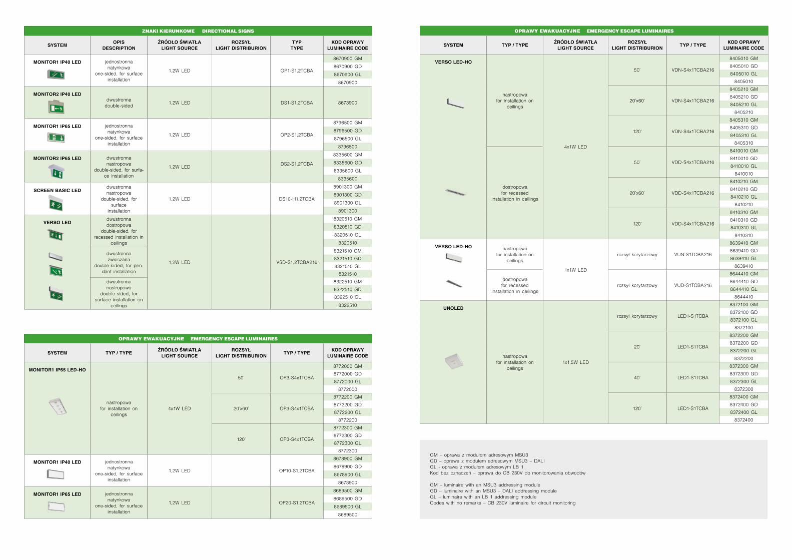
ZNAKI KIERUNKOWE • DIRECTIONAL SIGNS
SYSTEMOPIS
DESCRIPTIONŹRÓDŁO ŚWIATŁA
LIGHT SOURCEROZSYŁ
LIGHT DISTRIBURIONTYP
TYPEKOD OPRAWY
LUMINAIRE CODE
MONITOR1 IP40 LED jednostronna natynkowa
one-sided, for surface installation
1,2W LED OP1-S1,2TCBA
8670900 GM
8670900 GD
8670900 GL
8670900
MONITOR2 IP40 LEDdwustronnadouble-sided
1,2W LED DS1-S1,2TCBA 8673900
MONITOR1 IP65 LED jednostronna natynkowa
one-sided, for surface installation
1,2W LED OP2-S1,2TCBA
8796500 GM
8796500 GD
8796500 GL
8796500
MONITOR2 IP65 LED dwustronna nastropowa
double-sided, for surfa-ce installation
1,2W LEDDS2-S1,2TCBA
8335600 GM
8335600 GD
8335600 GL
8335600
SCREEN BASIC LEDdwustronna nastropowa
double-sided, for surface
installation
1,2W LED DS10-H1,2TCBA
8901300 GM
8901300 GD
8901300 GL
8901300
VERSO LEDdwustronna dostropowa
double-sided, for recessed installation in
ceilings
1,2W LED VSD-S1,2TCBA216
8320510 GM
8320510 GD
8320510 GL
8320510
dwustronna zwieszana
double-sided, for pen-dant installation
8321510 GM
8321510 GD
8321510 GL
8321510
dwustronna nastropowa
double-sided, for surface installation on
ceilings
8322510 GM
8322510 GD
8322510 GL
8322510
OPRAWY EWAKUACYJNE • EMERGENCY ESCAPE LUMINAIRES
SYSTEM TYP / TYPEŹRÓDŁO ŚWIATŁA
LIGHT SOURCEROZSYŁ
LIGHT DISTRIBURIONTYP / TYPE
KOD OPRAWY LUMINAIRE CODE
MONITOR1 IP65 LED-HO
nastropowafor installation on
ceilings4x1W LED
50° OP3-S4x1TCBA
8772000 GM
8772000 GD
8772000 GL
8772000
20°x60° OP3-S4x1TCBA
8772200 GM
8772200 GD
8772200 GL
8772200
120° OP3-S4x1TCBA
8772300 GM
8772300 GD
8772300 GL
8772300
MONITOR1 IP40 LED jednostronna natynkowa
one-sided, for surface installation
1,2W LED OP10-S1,2TCBA
8678900 GM
8678900 GD
8678900 GL
8678900
MONITOR1 IP65 LED jednostronna natynkowa
one-sided, for surface installation
1,2W LED OP20-S1,2TCBA
8689500 GM
8689500 GD
8689500 GL
8689500
GM – oprawa z modułem adresowym MSU3 GD – oprawa z modułem adresowym MSU3 – DALIGL - oprawa z modułem adresowym LB 1 Kod bez oznaczeń – oprawa do CB 230V do monitorowania obwodów
GM – luminaire with an MSU3 addressing module GD – luminaire with an MSU3 – DALI addressing module GL – luminaire with an LB 1 addressing module Codes with no remarks – CB 230V luminaire for circuit monitoring
GM – luminaire with an MSU3 addressing module • GD – luminaire with an MSU3 – DALI addressing module • GL – luminaire with an LB 1 addressing module • Codes with no remarks – CB 230V luminaire for circuit monitoring
OPRAWY EWAKUACYJNE • EMERGENCY ESCAPE LUMINAIRES
SYSTEM TYP / TYPEŹRÓDŁO ŚWIATŁA
LIGHT SOURCEROZSYŁ
LIGHT DISTRIBURIONTYP / TYPE
KOD OPRAWY LUMINAIRE CODE
VERSO LED-HO
nastropowafor installation on
ceilings
4x1W LED
50° VDN-S4x1TCBA216
8405010 GM
8405010 GD
8405010 GL
8405010
20°x60° VDN-S4x1TCBA216
8405210 GM
8405210 GD
8405210 GL
8405210
120° VDN-S4x1TCBA216
8405310 GM
8405310 GD
8405310 GL
8405310
dostropowafor recessed
installation in ceilings
50° VDD-S4x1TCBA216
8410010 GM
8410010 GD
8410010 GL
8410010
20°x60° VDD-S4x1TCBA216
8410210 GM
8410210 GD
8410210 GL
8410210
120° VDD-S4x1TCBA216
8410310 GM
8410310 GD
8410310 GL
8410310
VERSO LED-HO nastropowafor installation on
ceilings
1x1W LED
rozsył korytarzowy VUN-S1TCBA216
8639410 GM
8639410 GD
8639410 GL
8639410
dostropowafor recessed
installation in ceilingsrozsył korytarzowy VUD-S1TCBA216
8644410 GM
8644410 GD
8644410 GL
8644410
UNOLED
nastropowafor installation on
ceilings1x1,5W LED
rozsył korytarzowy LED1-S1TCBA
8372100 GM
8372100 GD
8372100 GL
8372100
20° LED1-S1TCBA
8372200 GM
8372200 GD
8372200 GL
8372200
40° LED1-S1TCBA
8372300 GM
8372300 GD
8372300 GL
8372300
120° LED1-S1TCBA
8372400 GM
8372400 GD
8372400 GL
8372400
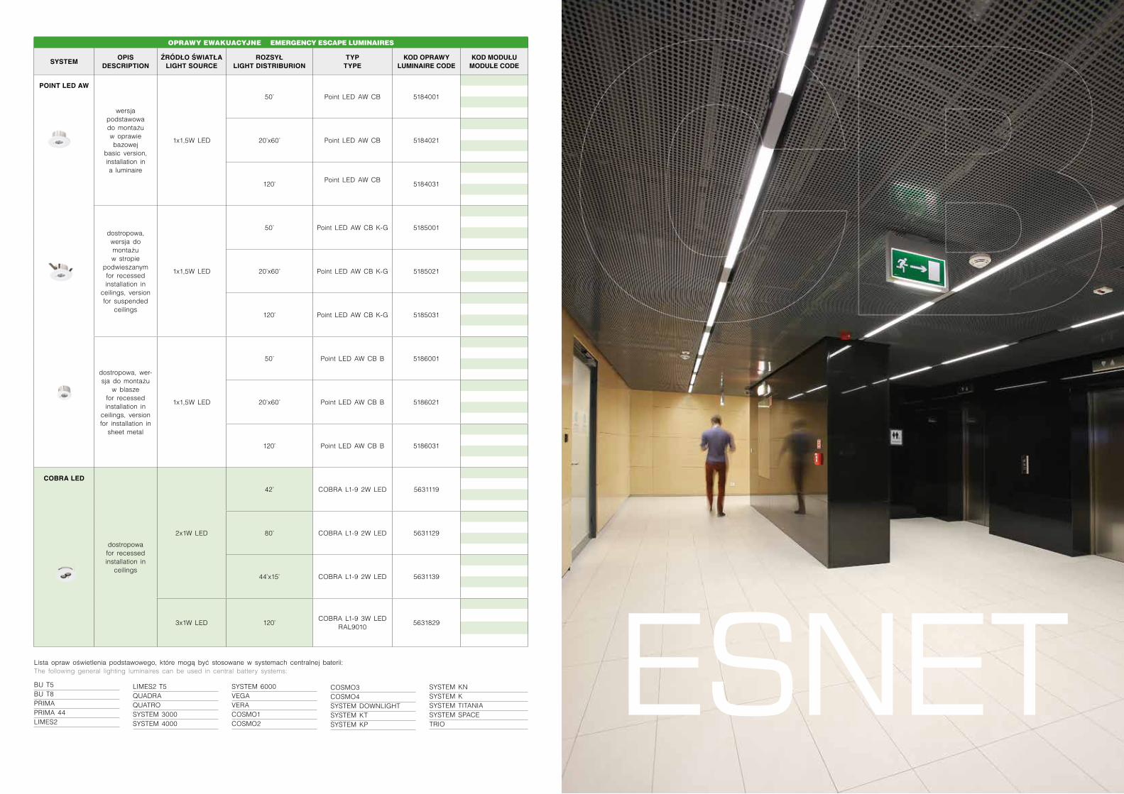
OPRAWY EWAKUACYJNE • EMERGENCY ESCAPE LUMINAIRES
SYSTEMOPIS
DESCRIPTIONŹRÓDŁO ŚWIATŁA
LIGHT SOURCEROZSYŁ
LIGHT DISTRIBURIONTYP
TYPEKOD OPRAWY
LUMINAIRE CODEKOD MODUŁU MODULE CODE
POINT LED AW
wersja podstawowado montażu w oprawie bazowej
basic version, installation in a luminaire
1x1,5W LED
50° Point LED AW CB 5184001
20°x60° Point LED AW CB 5184021
120°Point LED AW CB
5184031
dostropowa, wersja do montażu w stropie
podwieszanymfor recessed installation in
ceilings, version for suspended
ceilings
1x1,5W LED
50° Point LED AW CB K-G 5185001
20°x60° Point LED AW CB K-G 5185021
120° Point LED AW CB K-G 5185031
dostropowa, wer-sja do montażu
w blaszefor recessed installation in
ceilings, version for installation in
sheet metal
1x1,5W LED
50° Point LED AW CB B 5186001
20°x60° Point LED AW CB B 5186021
120° Point LED AW CB B 5186031
COBRA LED
dostropowafor recessed installation in
ceilings
2x1W LED
42° COBRA L1-9 2W LED 5631119
80° COBRA L1-9 2W LED 5631129
44°x15° COBRA L1-9 2W LED 5631139
3x1W LED 120°COBRA L1-9 3W LED
RAL90105631829
ESNET BU T5 BU T8 PRIMA PRIMA 44 LIMES2
Lista opraw oświetlenia podstawowego, które mogą być stosowane w systemach centralnej baterii:The following general lighting luminaires can be used in central battery systems:
LIMES2 T5QUADRA QUATRO SYSTEM 3000 SYSTEM 4000
SYSTEM 6000 VEGA VERA COSMO1 COSMO2
COSMO3 COSMO4 SYSTEM DOWNLIGHTSYSTEM KTSYSTEM KP
SYSTEM KNSYSTEM K SYSTEM TITANIASYSTEM SPACETRIO
LIGHT&DESIGN
58
SPÓŁKA ZAGRANICZNA FOREIGN SUBSIDIARY
ES-SYSTEM SCANDINAVIA ABKlarabergsviadukten 92111 64 Stockholmtel. +46 (0)8 585 000 35fax +46 (0)8 585 000 [email protected]
ES-SYSTEM S.A.30-701 KRAKÓW, ul. Przemysłowa 2tel. +48 12 656 36 33, +48 12 295 80 00fax +48 12 656 36 [email protected]
www.essystem.pl
ODDZIAŁ GDAŃSK80-435 GDAŃSK ul. Biała 1tel. 58 345 23 45, fax 58 341 91 [email protected]
ODDZIAŁ ŁÓDŹ91-072 ŁÓDŹ ul. Legionów 93/95tel. 42 633 60 13, fax 42 633 58 [email protected]
ODDZIAŁ MAZURY11-500 Giżycko, Wilkasy ul. Olsztyńska 2tel. 87 429 96 30-38, fax 87 429 96 [email protected]
ODDZIAŁ POZNAŃ61-894 POZNAŃ ul. Niezłomnych 1atel. 61 851 80 89, fax 61 851 76 [email protected]
ODDZIAŁ RZESZÓW35-307 RZESZÓW Al. Armii Krajowej 80tel. 17 850 82 85, fax 17 850 82 [email protected]
ODDZIAŁ ŚLĄSK44-100 GLIWICE ul. Wincentego Pola 16tel. 32 339 31 56, fax 32 339 31 [email protected]
ODDZIAŁ WARSZAWA03-301 WARSZAWA ul. Jagiellońska 78tel. 22 334 63 30 do 35, fax 22 334 63 [email protected]
ODDZIAŁ WROCŁAW52-315 WROCŁAW ul. Kobierzycka 18tel. 71 782 82 98, fax 71 783 29 [email protected]
CB


![REDOKSOWE PRZEMIANY OSCYLACYJNE DIFTALOCYJANIN …tchie.uni.opole.pl/CDEMfree/Waclawek_redoksowe.pdf · dwa niepodstawione ligandy ftalocyjaninowe [13], do złożonych, ... miały](https://img.pdfslide.tips/doc/110x75/5c785cbc09d3f21d538cd111/redoksowe-przemiany-oscylacyjne-diftalocyjanin-tchieuniopoleplcdemfreewaclawek.jpg)