Embed Size (px)
Citation preview

中文 . . . . . . . . . .5
英文 . . . . . . . . .21
用于水冷处理的ABB 变频器
快速安装和启动指南ACQ580-01 变频器外形尺寸 R6 至 R9
R0-R4
R5
CN
EN

相关手册列表
您可以在 Internet 上查找 PDF 格式的手册和其它产品文件。请参阅封底内的 Internet 上的文件库 一节。对于在 “文档 ” 资料库内没有提供的手册,请联络当地的 ABB 代表。
变频器手册和指南 代码 ( 英文 ) 代码 ( 中文 )ACQ580 泵控制程序固件手册 3AXD50000035867 3ABD00045443ACQ580-01 (0.75 至 250 kW) 硬件手册 3AXD50000035866 3ABD00045442
ACQ580-01 外形尺寸 R0 至 R5 快速安装和启动指南 3AXD50000035755 3ABD00045454ACQ580-01 外形尺寸 R6 至 R9 快速安装和启动指南 3AXD50000037301 3ABD00045455ACS-AP-x 助手控制盘用户手册 3AUA0000085685
可选件手册和指南
CDPI-01 通讯适配器模块用户手册 3AXD50000009929ACS-AP 控制盘 DPMP-01 安装平台 3AUA0000100140ACS-AP 控制盘 DPMP-02/03 安装平台 3AUA0000136205FDNA-01 DeviceNet™ 适配器模块用户手册 3AFE68573360FENA-01/-11/-21 Ethernet 适配器模块用户手册 3AUA0000093568FPBA-01 PROFIBUS DP 适配器模块用户手册 3AFE68573271FSCA-01 RS-485 适配器模块用户手册 3AUA0000109533外形尺寸 R6 至 R9 法兰安装快速指南 3AXD50000019099法兰安装补充手册 3AXD50000019100
T 工具和维护手册和指南
Drive composer PC 工具用户手册 3AUA0000094606变流器模块电容重整说明 3BFE64059629NETA-21 远程安装工具用户手册 3AUA00000969391NETA-21 远程安装工具安装和启动指南 3AUA0000096881
2016 北京 ABB 电气传动系统有限公司
3ABD00045455 版本 A 中文
3AXD50000037301 版本 B 英文
生效日期:2016-12-31

目录 3
目录
相关手册列表
ZH – R6…R9 快速安装指南遵循安全指导 . . . . . . . . . . . . . . . . . . . . . . . . . . . . . . . . . . . . . . . . . . . . . . . . . . . . . . . . . . . . . . . 5检查电容是否需要重整 . . . . . . . . . . . . . . . . . . . . . . . . . . . . . . . . . . . . . . . . . . . . . . . . . . . . . . . . 5选择电缆 . . . . . . . . . . . . . . . . . . . . . . . . . . . . . . . . . . . . . . . . . . . . . . . . . . . . . . . . . . . . . . . . . . 5确保冷却 . . . . . . . . . . . . . . . . . . . . . . . . . . . . . . . . . . . . . . . . . . . . . . . . . . . . . . . . . . . . . . . . . . 6保护变频器和输入电缆 . . . . . . . . . . . . . . . . . . . . . . . . . . . . . . . . . . . . . . . . . . . . . . . . . . . . . . . . 6在墙上安装变频器 . . . . . . . . . . . . . . . . . . . . . . . . . . . . . . . . . . . . . . . . . . . . . . . . . . . . . . . . . . . 6检查供电电缆和电机的绝缘 . . . . . . . . . . . . . . . . . . . . . . . . . . . . . . . . . . . . . . . . . . . . . . . . . . . . 7检查与 IT (浮地)和角接地的 TN 系统的兼容性 . . . . . . . . . . . . . . . . . . . . . . . . . . . . . . . . . . . 7
EMC 滤波器 . . . . . . . . . . . . . . . . . . . . . . . . . . . . . . . . . . . . . . . . . . . . . . . . . . . . . . . . . . . . 7压敏电阻 . . . . . . . . . . . . . . . . . . . . . . . . . . . . . . . . . . . . . . . . . . . . . . . . . . . . . . . . . . . . . . . 7断开 EMC 滤波器或压敏电阻 (必要时) . . . . . . . . . . . . . . . . . . . . . . . . . . . . . . . . . . . . . . 9
连接电缆 . . . . . . . . . . . . . . . . . . . . . . . . . . . . . . . . . . . . . . . . . . . . . . . . . . . . . . . . . . . . . . . . . 10连接控制电缆 . . . . . . . . . . . . . . . . . . . . . . . . . . . . . . . . . . . . . . . . . . . . . . . . . . . . . . . . . . . . . . 11默认 I/O 连接 . . . . . . . . . . . . . . . . . . . . . . . . . . . . . . . . . . . . . . . . . . . . . . . . . . . . . . . . . . . . . . 12安装可选模块 . . . . . . . . . . . . . . . . . . . . . . . . . . . . . . . . . . . . . . . . . . . . . . . . . . . . . . . . . . . . . . 13安装侧板和盖板 . . . . . . . . . . . . . . . . . . . . . . . . . . . . . . . . . . . . . . . . . . . . . . . . . . . . . . . . . . . . 13
中文 – 快速启动指南启动之前 . . . . . . . . . . . . . . . . . . . . . . . . . . . . . . . . . . . . . . . . . . . . . . . . . . . . . . . . . . . . . . . . . 15在 Hand-Off-Auto 控制盘上用 “ 初次启动助手 ” 启动 . . . . . . . . . . . . . . . . . . . . . . . . . . . . . . . . 15
EN – R6…R9 Quick installation guideObey the safety instructions . . . . . . . . . . . . . . . . . . . . . . . . . . . . . . . . . . . . . . . . . . . . . . . . . . 21Check if capacitors need to be reformed . . . . . . . . . . . . . . . . . . . . . . . . . . . . . . . . . . . . . . . . . 21Select the power cables . . . . . . . . . . . . . . . . . . . . . . . . . . . . . . . . . . . . . . . . . . . . . . . . . . . . . 22Ensure the cooling . . . . . . . . . . . . . . . . . . . . . . . . . . . . . . . . . . . . . . . . . . . . . . . . . . . . . . . . . . 22Protect the drive and input power cable . . . . . . . . . . . . . . . . . . . . . . . . . . . . . . . . . . . . . . . . . 22Install the drive on the wall . . . . . . . . . . . . . . . . . . . . . . . . . . . . . . . . . . . . . . . . . . . . . . . . . . . 22Check the insulation of the power cables and the motor . . . . . . . . . . . . . . . . . . . . . . . . . . . . . 23Check the compatibility with IT (ungrounded) and corner-grounded TN systems . . . . . . . . . . 23
EMC filter . . . . . . . . . . . . . . . . . . . . . . . . . . . . . . . . . . . . . . . . . . . . . . . . . . . . . . . . . . . . . 23Ground-to-phase varistor . . . . . . . . . . . . . . . . . . . . . . . . . . . . . . . . . . . . . . . . . . . . . . . . . 23Disconnect EMC filter or ground-to-phase varistor, if needed . . . . . . . . . . . . . . . . . . . . . 25
Connect the power cables . . . . . . . . . . . . . . . . . . . . . . . . . . . . . . . . . . . . . . . . . . . . . . . . . . . . 26Connect the control cables . . . . . . . . . . . . . . . . . . . . . . . . . . . . . . . . . . . . . . . . . . . . . . . . . . . 27Default I/O connections . . . . . . . . . . . . . . . . . . . . . . . . . . . . . . . . . . . . . . . . . . . . . . . . . . . . . . 28Install optional modules, if any . . . . . . . . . . . . . . . . . . . . . . . . . . . . . . . . . . . . . . . . . . . . . . . . 29Install side plates and covers . . . . . . . . . . . . . . . . . . . . . . . . . . . . . . . . . . . . . . . . . . . . . . . . . 29
EN – Quick start-up guideBefore you start . . . . . . . . . . . . . . . . . . . . . . . . . . . . . . . . . . . . . . . . . . . . . . . . . . . . . . . . . . . . 31
Safety

4 目录
Start-up with the First start assistant on a Hand-Off-Auto control panel . . . . . . . . . . . . . . . . 31
Compliance with the European Machinery Directive 2006/42/ECDeclaration of conformity . . . . . . . . . . . . . . . . . . . . . . . . . . . . . . . . . . . . . . . . . . . . . . . . . . . . 37
R6…R9 Figures AB . . . . . . . . . . . . . . . . . . . . . . . . . . . . . . . . . . . . . . . . . . . . . . . . . . . . . . . . . . . . . . . . . . . . . . . 39C . . . . . . . . . . . . . . . . . . . . . . . . . . . . . . . . . . . . . . . . . . . . . . . . . . . . . . . . . . . . . . . . . . . . . . . 39D . . . . . . . . . . . . . . . . . . . . . . . . . . . . . . . . . . . . . . . . . . . . . . . . . . . . . . . . . . . . . . . . . . . . . . . 40
R6…R9 Figures E
更多信息产品和服务咨询 . . . . . . . . . . . . . . . . . . . . . . . . . . . . . . . . . . . . . . . . . . . . . . . . . . . . . . . . . . . 43产品培训 . . . . . . . . . . . . . . . . . . . . . . . . . . . . . . . . . . . . . . . . . . . . . . . . . . . . . . . . . . . . . . . . . 43提供关于 ABB 传动手册的反馈信息 . . . . . . . . . . . . . . . . . . . . . . . . . . . . . . . . . . . . . . . . . . . . 43Internet 上的文件库 . . . . . . . . . . . . . . . . . . . . . . . . . . . . . . . . . . . . . . . . . . . . . . . . . . . . . . . . 43

ZH – R6…R9 快速安装指南 5
R0-R4
R6-R9
R6-R9
ZH
DA
DE
ES
FI
FR
IT
NL
PL
PT
RU
SV
TR
ZH
ZH – R6…R9 快速安装指南本指南简要介绍如何安装和启动变频器。如需了解完整的安装信息,请参阅 ACQ580-01 (0.75 至 250 kW) 硬件手册 (3ABD00045442 [ 中文 ])。有关启动说明,请参阅第15 页的中文 – 快速启动指南一章。
如需阅读手册,请访问 www.abb.com/drives/documents,搜索文件编号。
遵循安全指导
检查电容是否需要重整如果变频器已经有一年或更长时间未通电 (存放或未用),则必须重整电容。
您可以从序列号来判断生产时间。序列号可以在变频器所贴的型号标签上找到。序列号的格式是 MYYWWRXXXX。YY 和 WW 以如下方式说明生产年份和周次:
YY: 13、14、15、… 分别代表 2013、2014、2015、… WW: 01、02、03、… 分别代表第 1 周、第 2 周、第 3 周、…
有关电容重整的信息,请参阅互联网上的 Converter module capacitor reforming instructions (变频器模块电容重整说明) (3BFE64059629 [ 英语 ]),网址: www.abb.com/drives/documents。
选择电缆应根据当地规范选择能承载变频器型号标签上标称电流的电缆规格。
警告! 请遵循这些指导。如果您忽略指导,可能会导致受伤、死亡或设备损坏:
• 如果您不是具有资格的电工,请勿进行电气安装工作。
• 当接上主电源时,切勿在变频器、电机电缆或电机上操作。如果变频器已经连接到了输入电源,请在断开输入电源后等待 5 分钟。
• 当变频器或外部控制电路连接了电源时,切勿操作控制电缆。
• 起吊变频器时请使用变频器的吊耳。不要将变频器倾斜。变频器很重,而且重心较高。翻倒的变频器可能会导致人身伤害。
• 在安装时,确保不让钻孔和研磨出的碎屑进入变频器。
• 确保变频器下方的地面和安装变频器的墙面是阻燃的。

6 ZH – R6…R9 快速安装指南
R0-R4
R6-R9
R6-R9
ZH
DA
DE
ES
FI
FR
IT
NL
PL
PT
RU
SV
TR
ZH
确保冷却请参阅第 9 页上的表 I (UL:第 9 页上的表 II)了解散热信息。 变频器的允许操作温度范围是 -15 到 +50°C (+5 到 +122°F)。 不允许凝露或结霜。如需了解环境温度和降低额定值的更多信息,请参阅 ACQ580-01 (0.75 至 250 kW) 硬件手册(3ABD00045442 [ 中文 ]) 中 Technical data (技术数据)一章。
保护变频器和输入电缆有关保险丝的信息请参阅第 10 和第 10 页的表 III、 IV 和 V。
如果使用 gG 熔断器,请确保熔断器的熔断时间少于 0.5 秒。遵循当地法规。
在墙上安装变频器
警告! 变频器模块很重 (42 到 103 kg / 93 到 227 lb)。请使用合适的起吊设备。切勿人工抬起变频器模块。确保墙壁和固定装置能承载此重量。
请参阅第 39 页的图 R6…R9 Figures A。

ZH – R6…R9 快速安装指南 7
R0-R4
R6-R9
R6-R9
ZH
DA
DE
ES
FI
FR
IT
NL
PL
PT
RU
SV
TR
ZH
检查供电电缆和电机的绝缘在将输入电缆连接到变频器前,请按当地法规检查其绝缘。
请参阅第 39 的图 B。
1. 在将电机电缆和电机连接到变频器前,请检查其绝缘。使用 1000 V 直流测量各相导线之间的绝缘电阻,然后测量每相导线与保护性接地导线之间的绝缘电阻。典型电机的绝缘电阻必须超过 100 Mohm (参照值为 25°C 或 77°F 时测得)。对于其他电机的绝缘电阻,请参阅其制造商的说明。
注: 电机外壳内部的湿气会降低绝缘电阻。如果湿气长期存在,请干燥电机后再次测量。
检查与 IT (浮地)和角接地的 TN 系统的兼容性
n EMC 滤波器内置 EMC 滤波器不适用于 IT (浮地)系统或角接地的 TN 系统。在将变频器连接到电网前断开 EMC 滤波器的连接。查看第 8 页的表。
警告! 请勿将连接了内置 EMC 滤波器的变频器安装在 IT 系统 (浮地电网系统或高阻抗接地系统 [ 超过 30 ohm] 的电网系统),否则系统将可能会通过变
频器的 EMC 滤波器电容连接到接地线。这可能会导致危险或损坏变频器。
请勿将连接了内置 EMC 滤波器的变频器安装在角接地的 TN 系统,否则可能会损坏变频器。
注: 不连接内置 EMC 滤波器,变频器的 EMC 兼容性会显著降低。
n 压敏电阻压敏电阻不适用于 IT (浮地)系统。在将变频器连接到电网前断开压敏电阻的连接。查看第 8 页的表。
警告! 安装变频器时请勿将压敏电阻连接到 IT 系统 (未接地电网系统或高阻抗接地系统 [ 超过 30 ohm] 的电网系统),否则会损坏压敏电阻的电路。

8 ZH – R6…R9 快速安装指南
R0-R4
R6-R9
R6-R9
ZH
DA
DE
ES
FI
FR
IT
NL
PL
PT
RU
SV
TR
ZH
如须断开 EMC 滤波器 (EMC) 或压敏电阻 (VAR),请查看下表。具体操作说明请参阅第 9 页。
外形尺寸 EMC 滤波器
(EMC)
压敏电阻 (VAR)
对称接地 TN 系统(TN-S 系统)1
角接地 TN 系统 2 IT 系统 (浮地或高阻抗接地系统
[>30 ohms])3
R6…R9 EMC(2 个螺
钉))
- 不断开 断开 断开
- VAR(1 个螺
钉)
不断开 不断开 断开
1 2 3
变频器
PE
N
L3
L2
L1
变频器 变频器
PEL3L2
L1
L3
L2
L1

ZH – R6…R9 快速安装指南 9
R0-R4
R6-R9
R6-R9
ZH
DA
DE
ES
FI
FR
IT
NL
PL
PT
RU
SV
TR
ZH
n 断开 EMC 滤波器或压敏电阻 (必要时)如果必要时要断开内置 EMC 滤波器或压敏电阻,请执行以下操作:
1. 关断变频器电源。
2. 打开前盖 (如果尚未打开),请参阅第 39 页图 R6…R9 Figures A 上的步骤 5,IP21 和步骤 5,IP55。
3. 卸下两颗 EMC 螺钉,断开内置 EMC 滤波器。4. 卸下压敏电阻螺钉,断开压敏电阻。
3
4
33
34

10 ZH – R6…R9 快速安装指南
R0-R4
R6-R9
R6-R9
ZH
DA
DE
ES
FI
FR
IT
NL
PL
PT
RU
SV
TR
ZH
连接电缆请参阅第 39 页的图 C。电机电缆请使用对称屏蔽线。如果屏蔽电缆为变频器或电机的唯一保护接地线,请确保地线有足够的导电能力。
1. 将本地语言的残余电压警告贴纸贴在控制电路板旁。
2. 卸下电缆接入盒的侧板:松开紧固螺钉并把侧板滑出。
3. 用螺丝刀松开搭扣,并将护罩拉出,卸下供电电缆端子上的护罩。
4. 在遮蔽盖板上对应安装电缆的位置打孔。
5. 在橡胶绝缘圈上切出足够大的孔。将绝缘圈套入电缆。
6. 如图所示准备好供电电缆和电机的两端。注:将屏蔽线裸线做 360 度接地。将黄绿色双绞屏蔽线标记为保护接地线。
7. 将电缆从底板的孔中穿过并将绝缘圈固定到孔上 (电机电缆在右,输入电缆在左)。
8. 连接电机电缆: • 在接地夹下将屏蔽层做 360 度接地 (8a)。• 将电缆的双绞线屏蔽层连接到接地端子 (8b)。• 将电缆的相线连接到 T1/U、T2/V 和 T3/W 端子。按图中给出的力矩拧紧螺钉
(8c)。注:相线 (R8, R9) 是可拆卸的。
9. 按步骤 8 中的方法连接供电电缆。使用端子 L1、L2 和 L3
10.R8…R9: 如果您要平行安装,请安装平行电缆的第二个接地支架。重复步骤 5...9。
11.安装控制电缆的接地支架。
12.在电源端子上装回遮蔽盖板。
13.将导线在变频器单元外机械紧固。
14.在电机端将电机电缆屏蔽层接地。为实现最小的射频干扰,在电机接线盒的穿孔部分将电机电缆屏蔽层做 360 度接地。

ZH – R6…R9 快速安装指南 11
R0-R4
R6-R9
R6-R9
ZH
DA
DE
ES
FI
FR
IT
NL
PL
PT
RU
SV
TR
ZH
连接控制电缆请参阅第 40 页的图 D。图中所示为一根模拟信号电缆和一根数字信号电缆的示例。请按所使用的默认配置进行连接。 水冷默认配置的默认连接见第 12 页的默认 I/O 连接一节。
模拟信号电缆连接示例:
1. 在橡胶绝缘圈上切一个足够大的孔,然后将绝缘圈套入电缆。将电缆从底板的孔中穿过并将绝缘圈固定到孔上。
2. 将剥开的电缆外屏蔽层在接地夹下做 360 度接地。靠近控制电路板端子的电缆剥开部分要尽可能少。对于模拟信号电缆,在 SCR1 端子处将成对电缆屏蔽和接地线也做接地。将电缆以机械方式固定在控制板下的夹子上。
3. 如图所示进行布线。
4. 将导线连接到控制板的对应端子上,并紧固到 0.5…0.6 N·m (0.4 lbf·ft).
5. 将全部控制电缆都绑到提供的电缆捆绑架上。
6. 将未使用的橡胶绝缘圈装回到穿孔板的孔上。
12 ZH – R6…R9 快速安装指南
R0-R4
R6-R9
R6-R9
ZH
DA
DE
ES
FI
FR
IT
NL
PL
PT
RU
SV
TR
ZH
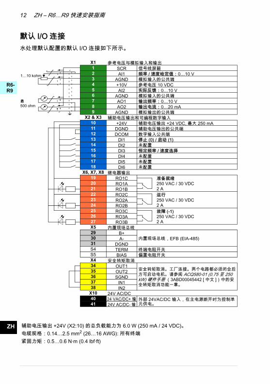
默认 I/O 连接水处理默认配置的默认 I/O 连接如下所示。
最500 ohm
1…10 kohm
X1 参考电压与模拟输入和输出1 SCR 信号线屏蔽2 AI1 频率 / 速度给定值:0…10 V3 AGND 模拟输入的公共端4 +10V 参考电压 10 VDC5 AI2 实际反馈: 0…10 V6 AGND 模拟输入的公共端7 AO1 输出频率: 0…10 V8 AO2 输出电流: 0…20 mA9 AGND 模拟输出的公共端
X2 & X3 辅助电压输出和可编程数字输入10 +24V 辅助电压输出 +24 VDC, 最大 250 mA11 DGND 辅助电压输出的公共端12 DCOM 数字输入公共端13 DI1 停止 (0) / 启动 (1) 14 DI2 未配置 15 DI3 恒定频率 / 速度选择16 DI4 未配置17 DI5 未配置18 DI6 未配置
X6, X7, X8 继电器输出19 RO1C 准备就绪
250 VAC / 30 VDC2 A
20 RO1A21 RO1B22 RO2C 运行
250 VAC / 30 VDC 2 A
23 RO2A24 RO2B25 RO3C 故障 (-1)
250 VAC / 30 VDC2 A
26 RO3A27 RO3BX5 内置现场总线29 B+
内置现场总线,EFB (EIA-485)30 A-31 DGNDS4 TERM 终端电阻开关S5 BIAS 偏置电阻开关X4 安全转矩取消34 OUT1 安全转矩取消。工厂连接。 两个电路都必须闭合后
方可启动电机。请参阅 ACQ580-01 (0.75 至 250 kW) 硬件手册 (3ABD00045442 [ 中文 ])中的安全转矩取消功能一章。
35 OUT236 SGND37 IN138 IN2
X10 24V AC/DC40 24 VAC/DC+ 输 外部 24VAC/DC 输入,在主电源断开时为控制单
元供电。41 24V AC/DC- 输
辅助电压输出 +24V (X2:10) 的总负载能力为 6.0 W (250 mA / 24 VDC)。电缆规格:0.14…2.5 mm2 (26…16 AWG): 所有终端紧固力矩:0.5…0.6 N·m (0.4 lbf·ft)

ZH – R6…R9 快速安装指南 13
R0-R4
R6-R9
R6-R9
ZH
DA
DE
ES
FI
FR
IT
NL
PL
PT
RU
SV
TR
ZH
安装可选模块请参阅 ACQ580-01 (0.75 至 250 kW) 硬件手册 (3ABD00045442 [ 中文 ]) 中的Electrical installation (电气安装)一章。
安装侧板和盖板请参阅第 41 页的图 R6…R9 Figures E。
IP21
1. 装回电缆接入盒的侧板。用螺丝刀将紧固螺钉拧紧。
2. 从下方将模块上的接线盒盖板滑入,直到盖板牢牢卡住。
3. 装回模块盖板。用螺丝刀将两颗紧固螺钉拧紧。
IP55
1. 装回模块盖板。用螺丝刀将两颗紧固螺钉拧紧。
有关启动说明,请参阅第 15 页的 中文 – 快速启动指南一章。

14 ZH – R6…R9 快速安装指南
R0-R4
R6-R9
R6-R9
ZH
DA
DE
ES
FI
FR
IT
NL
PL
PT
RU
SV
TR
ZH

中文 – 快速启动指南 15
0-4
0-9
H
A
E
S
I
R
T
L
L
T
U
V
R
H
RR
RR
Z
D
D
E
F
F
I
N
P
P
R
S
T
Z
中文 – 快速启动指南本指南介绍如何在 Hand-Off-Auto 控制盘上使用 “ 首次启动助手 ” 启动变频器。 如需了解有关启动的完整信息,请参阅 ACQ580 固件手册 (3ABD00045443[ 英语 ])。
启动之前确保按照第 7 页的中文 – R0…R4 快速安装指南一章 (外形尺寸 R0…R4)或第 17页的中文 – R5 快速安装指南一章 (外形尺寸 R5)所述安装变频器。
在 Hand-Off-Auto 控制盘上用 “ 初次启动助手 ” 启动
安全
确保安装工作已经完成。确保变频器的盖板和电缆盒位置就位。
检查确保电机的启动不造成任何危险。如果由于不正确的转动方向可能导致损坏,请将被驱动的机器断开。
使用助手型控制盘的提示显示屏底部的两个命令 (右图的选项和菜单)显示了屏幕下方的两个软键 和 的功能。分配给软键的命令在不同上下文环境中会有所不同。用 、 、 和 键移动光标和 / 或根据当前视图修改值。
键会显示一个上下文相关的帮助页面。
1 – 首次启动助手引导的设置:语言、日期和时间以及电机额定值
请准备好电机铭牌数据。给变频器上电。
?

16 中文 – 快速启动指南
R0-R4
R0-R9
ZH
DA
DE
ES
FI
FR
IT
NL
PL
PT
RU
SV
TR
ZH
“ 首次启动助手 ” 会引导您完成首次启动。 助手会自动开始运行。等待控制控制盘进入如右图所示的画面。选择您想使用的语言 (如果尚未选中),然后按 (OK)。注: 选择了语言后,控制盘需要几分钟时间来激活。
选择启动设置并按 (下一步)。
设置日期和时间以及日期时间显示格式。• 按 进入所选行的编辑视图。• 用 和 滚动视图。 按 ( 下一步 ) 进入下一个视图。
在编辑视图上修改数值:左右移动光标• 用 和 左右移动光标。
• 用 和 修改数值。• 按 (保存 ) 接受新设置,或按 (取消 )
来返回原先视图而不做任何修改。
如果需要,可在控制盘上修改单位:• 按 进入所选行的编辑视图。• 用 和 滚动视图。 按 进入下一个视图 ( 下一步 )。

中文 – 快速启动指南 17
0-4
0-9
H
A
E
S
I
R
T
L
L
T
U
V
R
H
RR
RR
Z
D
D
E
F
F
I
N
P
P
R
S
T
Z
要给变频器命名 (显示在顶部),按 。
如果您不想改变默认名称 (ACQ580),按 ( 下一步 ) 继续。有关编辑文字的更多信息,请参阅 ACQ580 固件手册 (3ABD00045443[ 英语 ])。提示:为变频器命名,例如,泵 1。
电机的下列额定值设置请参考电机或泵铭牌。完全按照电机或泵铭牌所示输入值。感应 (异步)电机铭牌示例:
检查确认电机数据正确。这些值是根据变频器规格预先定义的,但是您应该确认它们与电机对应。从输入电机类型开始。• 按 进入所选行的编辑视图。• 用 和 滚动视图。 电机额定 cos Φ 和额定转矩是选填项目。按 (下一步)继续。
根据需要调节限值。• 按 进入所选行的编辑视图。• 用 和 滚动视图。 按 显示下一个视图 ( 下一步 )。
M2AA 200 MLA 4
14751475
1470147014751770
32.556
34595459
0.830.83
0.830.830.830.83
3GAA 202 001 - ADA
180
IEC 34-1
6210/C36312/C3
Cat. no
35 30 30 30
30 3050
5050
505060
690 Y400 D660 Y
380 D415 D440 D
V Hz kW r/min A cos IA/IN t E/s
Ins.cl. F IP 55No
IEC 200 M/L 55
3 motor
ABB Motors
18 中文 – 快速启动指南
R0-R4
R0-R9
ZH
DA
DE
ES
FI
FR
IT
NL
PL
PT
RU
SV
TR
ZH
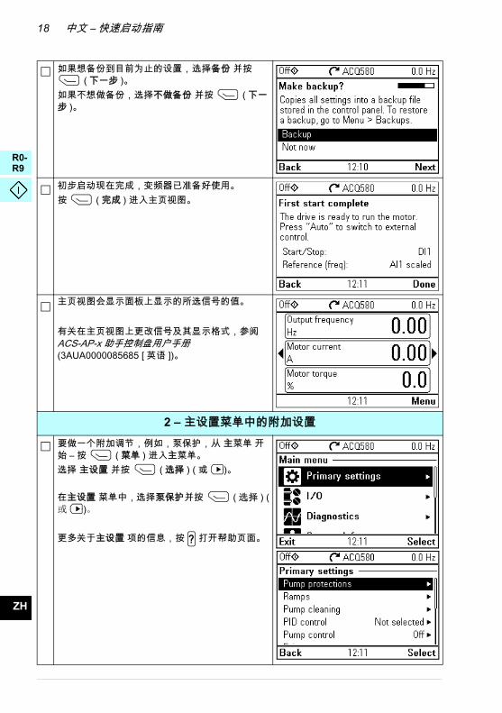
如果想备份到目前为止的设置, 选择备份 并按 ( 下一步 )。
如果不想做备份,选择不做备份 并按 ( 下一步 )。
初步启动现在完成,变频器已准备好使用。按 ( 完成 ) 进入主页视图。
主页视图会显示面板上显示的所选信号的值。
有关在主页视图上更改信号及其显示格式,参阅 ACS-AP-x 助手控制盘用户手册 (3AUA0000085685 [ 英语 ])。
2 – 主设置菜单中的附加设置要做一个附加调节,例如,泵保护, 从 主菜单 开始 – 按 ( 菜单 ) 进入主菜单。选择 主设置 并按 ( 选择 ) ( 或 )。
在主设置 菜单中,选择泵保护并按 ( 选择 ) (或 )。
更多关于主设置 项的信息,按 打开帮助页面。?
中文 – 快速启动指南 19
0-4
0-9
H
A
E
S
I
R
T
L
L
T
U
V
R
H
RR
RR
Z
D
D
E
F
F
I
N
P
P
R
S
T
Z
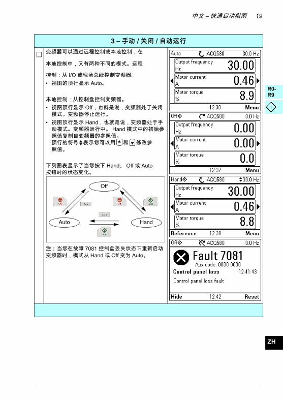
3 – 手动 / 关闭 / 自动运行变频器可以通过远程控制或本地控制,在
本地控制中,又有两种不同的模式。远程
控制:从 I/O 或现场总线控制变频器。 • 视图的顶行显示 Auto。
本地控制:从控制盘控制变频器。• 视图顶行显示 Off,也就是说,变频器处于关闭
模式。变频器停止运行。• 视图顶行显示 Hand,也就是说,变频器处于手
动模式。变频器运行中。 Hand 模式中的初始参照值复制自变频器的参照值。顶行的符号 表示您可以用 和 修改参照值。
下列图表显示了当您按下 Hand、 Off 或 Auto按钮时的状态变化。
注: 当您在故障 7081 控制盘丢失状态下重新启动变频器时,模式从 Hand 或 Off 变为 Auto。
Auto
Off
Hand

20 中文 – 快速启动指南
R0-R4
R0-R9
ZH
DA
DE
ES
FI
FR
IT
NL
PL
PT
RU
SV
TR
ZH

EN – R6…R9 Quick installation guide 21
0-4
6-9
6-9
N
E
S
R
T
U
V
H
RR
RR
RR
E
D
E
F
I
R
S
Z
EN – R6…R9 Quick installation guide
This guide briefly describes how to install the drive. For complete information on installation, see ACQ580-01 (0.75 to 250 kW) hardware manual (3AXD50000035866 [English]). For start-up instructions, see chapter EN – Quick start-up guide on page 31.
To read a manual, go to www.abb.com/drives/documents and search for the document number.
Obey the safety instructions
Check if capacitors need to be reformed
If the drive has not been powered (either in storage or unused) for over one year, you must reform the capacitors.
You can determine the manufacturing time from the serial number, which you find on the type designation label attached to the drive. The serial number is of format MYYWWRXXXX. YY and WW tell the manufacturing year and week as follows:
YY: 13, 14, 15, … for 2013, 2014, 2015, … WW: 01, 02, 03, … for week 1, week 2, week 3, …
WARNING! Obey these instructions. If you ignore them, injury or death, or damage to the equipment can occur:
• If you are not a qualified electrician, do not do electrical installation work.
• Do not work on the drive, motor cable or motor when main power is applied. If the drive is already connected to the input power, wait for 5 minutes after disconnecting the input power.
• Do not work on the control cables when power is applied to the drive or to the external control circuits.
• Use the lifting eyes of the drive when you lift the drive. Do not tilt the drive. The drive is heavy and its center of gravity is high. An overturning drive can cause physical injury.
• Make sure that debris from borings and grindings does not enter the drive when installing.
• Make sure that the floor below the drive and the wall where the drive is installed are non-flammable.

22 EN – R6…R9 Quick installation guide
R0-R4
R6-R9
R6-R9
EN
DE
ES
FR
IT
RU
SV
For information on reforming the capacitors, see Converter module capacitor reforming instructions (3BFE64059629 [English]), available on the Internet at www.abb.com/drives/documents.
Select the power cables
Size the power cables according to local regulations to carry the nominal current given on the type designation label of your drive.
Ensure the cooling
See table I on page 9 (UL: table II on page 9) for the heat dissipation. The allowed operating temperature range of the drive is -15 to +50 °C (+5 to +122 °F). No condensation or frost is allowed. For more information on the ambient temperature and derating, see chapter Technical data in ACQ580-01 (0.75 to 250 kW) hardware manual (3AXD50000035866 [English]).
Protect the drive and input power cable
See tables III, IV and V on page 10 for the fuses.
If you use gG fuses, make sure that the operating time of the fuse is below 0.5 seconds. Follow the local regulations.
Install the drive on the wall
Warning! The drive module is heavy (42 to 103 kg / 93 to 227 lb). Use a suitable lifting device. Do not lift the module manually. Make sure that the wall
and the fixing devices can carry the weight.
See figure R6…R9 Figures A on page 39.

EN – R6…R9 Quick installation guide 23
0-4
6-9
6-9
N
E
S
R
U
V
H
RR
RR
RR
E
D
E
F
IT
R
S
Z
Check the insulation of the power cables and the motor
Check the insulation of the input cable according to local regulations before connecting it to the drive.
See figure B on page 39.
1. Check the insulation of the motor cable and motor before connecting it to the drive. Measure the insulation resistance between each phase conductor and then between each phase conductor and the Protective Earth conductor using a measuring voltage of 1000 V DC. The insulation resistance of a typical motor must exceed 100 Mohm (reference value at 25 °C or 77 °F). For the insulation resistance of motors, see the manufacturer’s instructions.
Note: Moisture inside the motor casing will reduce the insulation resistance. If moisture is suspected, dry the motor and repeat the measurement.
Check the compatibility with IT (ungrounded) and corner-grounded TN systems
EMC filter
The internal EMC filter is not suitable for use on an IT (ungrounded) system or on a corner-grounded TN system. Disconnect the EMC filter before connecting the drive to the supply network. Check the table on page 24.
WARNING! Do not install the drive with the internal EMC filter connected on an IT system (an ungrounded power system or a high-resistance-grounded [over
30 ohms] power system), otherwise the system will be connected to ground potential through the EMC filter capacitors of the drive. This can cause danger, or damage the drive.
Do not install the drive with the internal EMC filter connected on a corner-grounded TN system, otherwise the drive will be damaged.
Note: When the internal EMC filter is disconnected, the drive EMC compatibility is considerably reduced.
Ground-to-phase varistor
The ground-to-phase varistor is not suitable for use on an IT (ungrounded) system. Disconnect the ground-to-phase varistor before connecting the drive to the supply network. Check the table on page 24.

24 EN – R6…R9 Quick installation guide
R0-R4
R6-R9
R6-R9
EN
DE
ES
FR
IT
RU
SV
WARNING! Do not install the drive with the ground-to-phase varistor connected on an IT system (an ungrounded power system or a high-
resistance-grounded [over 30 ohms] power system), otherwise the varistor circuit can be damaged.
Check from the table below if you have to disconnect the EMC filter (EMC) or ground-to-phase varistor (VAR). For instructions on how to do this, see page 25.
Frame sizes
EMC filter
(EMC)
Ground-to-phase varistor
(VAR)
Symmetrically grounded TN
systems (TN-S systems) 1
Corner grounded TN systems 2
IT systems (ungrounded or high-resistance grounded [>30
ohms]) 3
R6…R9 EMC(2 screws)
- Do not disconnect Disconnect Disconnect
- VAR(1 screw)
Do not disconnect Do not disconnect Disconnect
1 2 3
Drive
PE
N
L3
L2
L1
Drive Drive
PEL3L2
L1
L3
L2
L1

EN – R6…R9 Quick installation guide 25
0-4
6-9
6-9
N
E
S
R
U
V
H
RR
RR
RR
E
D
E
F
IT
R
S
Z
Disconnect EMC filter or ground-to-phase varistor, if needed
To disconnect the internal EMC filter or ground-to-phase varistor, if needed, do as follows:
1. Switch off the power from the drive.
2. Open the front cover, if not already opened, see steps 5, IP21 and 5, IP55 in figure R6…R9 Figures A on page 39.
3. To disconnect the internal EMC filter, remove the two EMC screws.
4. To disconnect the ground-to-phase varistor, remove the varistor screw.
3
4
33
34

26 EN – R6…R9 Quick installation guide
R0-R4
R6-R9
R6-R9
EN
DE
ES
FR
IT
RU
SV
Connect the power cables
See figure C on page 39. Use symmetrical shielded cable for motor cabling. If the cable shield is the sole PE conductor for drive or motor, make sure that is has sufficient conductivity for the PE.
1. Attach the residual voltage warning sticker in the local language next to the control board.
2. Remove the side plates of the cable entry box: Loosen the retaining screws and slide the walls out.
3. Remove the shroud on the power cable terminals by releasing the clips with a screwdriver and pulling the shroud out.
4. Knock out holes for the cables to be installed.
5. Cut an adequate hole into the rubber grommet. Slide the grommet onto the cable.
6. Prepare the ends of the input power cable and motor cable as illustrated in the figure. Note: The bare shield will be grounded 360 degrees. Mark the pigtail made from the shield as a PE conductor with yellow-and-green color.
7. Slide the cables through the holes of the bottom plate and attach the grommets to the holes (the motor cable to the right and the input power cable to the left).
8. Connect the motor cable:
• Ground the shield 360 degrees under the grounding clamp (8a).
• Connect the twisted shield of the cable to the grounding terminal (8b).
• Connect the phase conductors of the cable to terminals T1/U, T2/V and T3/W. Tighten the screws to the torque given in the figure (8c). Note: Phase conductors (R8, R9) are detachable.
9. Connect the input power cable as in step 8. Use terminals L1, L2 and L3.
10. R8…R9: If you install parallel, install the second grounding shelf for the parallel power cables. Repeat steps 5...9.
11. Install the grounding shelf for the control cables.
12. Reinstall the shroud on the power terminals.
13. Secure the cables outside the unit mechanically.
14. Ground the motor cable shield at the motor end. For minimum radio frequency interference, ground the motor cable shield 360 degrees at the lead-through of the motor terminal box.

EN – R6…R9 Quick installation guide 27
0-4
6-9
6-9
N
E
S
R
U
V
H
RR
RR
RR
E
D
E
F
IT
R
S
Z
Connect the control cables
See figure D on page 40. It shows an example with one analog signal cable and one digital signal cable. Make the connections according to the default configuration in use. The default connections of the Water default configuration are shown in section Default I/O connections on page 28.
Example of connecting an analog signal cable:
1. Cut an adequate hole into the rubber grommet and slide the grommet onto the cable. Slide the cable through a hole of the bottom plate and attach the grommet to the hole.
2. Ground the stripped outer shield of the cable 360 degrees under the grounding clamp. Keep the cable otherwise unstripped as close to the terminals of the control board as possible. For analog signal cables, ground also the pair-cable shields and grounding wire at the SCR1 terminal. Secure the cables mechanically at the clamps below the control board.
3. Route the cable as shown in the figure.
4. Connect the conductors to the appropriate terminals of the control board and tighten to 0.5…0.6 N·m (0.4 lbf·ft).
5. Tie all control cables to the provided cable tie mounts.
6. Put the unused rubber grommets to the holes in the lead-through plate.

28 EN – R6…R9 Quick installation guide
R0-R4
R6-R9
R6-R9
EN
DE
ES
FR
IT
RU
SV
Default I/O connections
Default I/O connections of the Water default configuration are shown below.
max.500 ohm
1…10 kohm
X1 Reference voltage and analog inputs and outputs1 SCR Signal cable shield (screen)2 AI1 Output frequency/speed reference: 0…10 V3 AGND Analog input circuit common4 +10V Reference voltage 10 V DC5 AI2 Actual feedback: 0…10 V6 AGND Analog input circuit common7 AO1 Output frequency: 0…10 V8 AO2 Output current: 0…20 mA9 AGND Analog output circuit common
X2 & X3 Aux. voltage output and programmable digital inputs10 +24V Aux. voltage output +24 V DC, max. 250 mA11 DGND Aux. voltage output common12 DCOM Digital input common for all13 DI1 Stop (0) / Start (1) 14 DI2 Not configured 15 DI3 Constant frequency/speed selection16 DI4 Not configured17 DI5 Not configured18 DI6 Not configured
X6, X7, X8 Relay outputs19 RO1C Ready run
250 V AC / 30 V DC2 A
20 RO1A21 RO1B22 RO2C Running
250 V AC / 30 V DC 2 A
23 RO2A24 RO2B25 RO3C Fault (-1)
250 V AC / 30 V DC2 A
26 RO3A27 RO3BX5 Embedded fieldbus29 B+
Embedded fieldbus, EFB (EIA-485)30 A-31 DGNDS4 TERM Termination switchS5 BIAS Bias resistors switchX4 Safe torque off34 OUT1 Safe torque off. Factory connection. Both circuits
must be closed for the drive to start. See chapter The Safe torque off function in ACQ580-01 (0.75 to 250 kW) hardware manual (3AXD50000035866 [English]).
35 OUT236 SGND37 IN138 IN2
X10 24 V AC/DC40 24 V AC/DC+ in Ext. 24V AC/DC input to power up the control unit
when the main supply is disconnected. 41 24 V AC/DC- in
Total load capacity of the Auxiliary voltage output +24V (X2:10) is 6.0 W (250 mA / 24 V DC).
Wire sizes: 0.14…2.5 mm2 (26…16 AWG): All terminals
Tightening torques: 0.5…0.6 N·m (0.4 lbf·ft)

EN – R6…R9 Quick installation guide 29
0-4
6-9
6-9
N
E
S
R
U
V
H
RR
RR
RR
E
D
E
F
IT
R
S
Z
Install optional modules, if any
See chapter Electrical installation in ACQ580-01 (0.75 to 250 kW) hardware manual (3AXD50000035866 [English]).
Install side plates and covers
See figure R6…R9 Figures E on page 41.
IP21
1. Reinstall the side plates of the cable entry box. Tighten the retaining screws with a screwdriver.
2. Slide the cover of the cable entry box on the module from below until the cover snaps into place.
3. Reinstall the module cover. Tighten the two retaining screws with a screwdriver.
IP55
1. Reinstall the module cover. Tighten the two retaining screws with a screwdriver.
For start-up instructions, see chapter EN – Quick start-up guide on page 31.

30 EN – R6…R9 Quick installation guide
R0-R4
R6-R9
R6-R9
EN
DE
ES
FR
IT
RU
SV

EN – Quick start-up guide 31
0-4
0-9
N
E
S
R
T
U
V
RR
RR
E
D
E
F
I
R
S
EN – Quick start-up guide
This guide describes how to start-up the drive using the First start assistant on the Hand-Off-Auto control panel. For complete information on start-up, see ACQ580 firmware manual (3AXD50000035867 [English]).
Before you start
Ensure that the drive has been installed as described in chapter EN – R6…R9 Quick installation guide on page 21 (frames R6…R9).
Start-up with the First start assistant on a Hand-Off-Auto control panel
Safety
Make sure that the installation work is complete. Make sure that cover of the drive and the cable box, if included, are on place.
Check that the starting of the motor does not cause any danger. De-couple the driven machine if there is a risk of damage in case of an incorrect direction of
rotation.
Hints on using the assistant control panel
The two commands at the bottom of the display (Options and Menu in the figure on the right), show the functions of the two softkeys and
located below the display. The commands assigned to the softkeys vary depending on the context.
Use keys , , and to move the cursor and/or change values depending on the active view.
Key shows a context-sensitive help page.
1 – First start assistant guided settings:Language, date and time, and motor nominal values
Have the motor or pump name plate data at hand.
Power up the drive.
?
32 EN – Quick start-up guide
R0-R4
R0-R9
EN
DE
ES
FR
IT
RU
SV
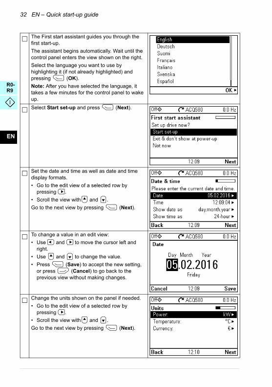
The First start assistant guides you through the first start-up.
The assistant begins automatically. Wait until the control panel enters the view shown on the right.
Select the language you want to use by highlighting it (if not already highlighted) and pressing (OK).
Note: After you have selected the language, it takes a few minutes for the control panel to wake up.
Select Start set-up and press (Next).
Set the date and time as well as date and time display formats.
• Go to the edit view of a selected row by pressing .
• Scroll the view with and .
Go to the next view by pressing (Next).
To change a value in an edit view:
• Use and to move the cursor left and right.
• Use and to change the value.
• Press (Save) to accept the new setting, or press (Cancel) to go back to the previous view without making changes.
Change the units shown on the panel if needed.
• Go to the edit view of a selected row by pressing .
• Scroll the view with and .
Go to the next view by pressing (Next).

EN – Quick start-up guide 33
0-4
0-9
N
E
S
R
T
U
V
RR
RR
E
D
E
F
I
R
S
To give the drive a name that will be shown at the top, press . If you do not want to change the default name (ACQ580), continue by pressing (Next).
For information on editing text, see ACQ580 firmware manual (3AXD50000035867 [English]).
Hint: Name the drive, for example, Pump 1.
Refer to the motor or pump nameplate for the following nominal value settings of the motor. Enter the values exactly as shown on the motor or pump nameplate.
Example of a nameplate of an induction (asynchronous) motor:
Check that the motor data is correct. Values are predefined on the basis of the drive size but you should verify that they correspond to the motor.
Start with the motor type.Go to the edit view of a selected row by pressing .
• Scroll the view with and .
Motor nominal cosΦ and nominal torque are optional.
Press (Next) to continue.
Adjust the limits according to your needs.
• Go to the edit view of a selected row by pressing .
• Scroll the view with and .
Go to the next view by pressing (Next).
M2AA 200 MLA 4
14751475
1470147014751770
32.556
34595459
0.830.83
0.830.830.830.83
3GAA 202 001 - ADA
180
IEC 34-1
6210/C36312/C3
Cat. no
35 30 30 30
30 3050
5050
505060
690 Y400 D660 Y
380 D415 D440 D
V Hz kW r/min A cos IA/IN t E/s
Ins.cl. F IP 55No
IEC 200 M/L 55
3 motor
ABB Motors

34 EN – Quick start-up guide
R0-R4
R0-R9
EN
DE
ES
FR
IT
RU
SV
If you want to make a backup of the settings made so far, select Backup and press (Next).
If you do not want to make a backup, select Not now and press (Next).
The first start is now complete and the drive is ready for use.
Press (Done) to enter the Home view.
The Home view monitoring the values of the selected signals is shown on the panel.
For changing the signals and their display style shown in the Home view, see ACS-AP-x assistant control panels user’s manual (3AUA0000085685 [English]).
2 – Additional settings in the Primary settings menu
Make any additional adjustments, for example, pump protections, starting from the Main menu – press (Menu) to enter the Main menu.
Select Primary settings and press (Select) (or ).
In the Primary settings menu, select Pump protections and press (Select) (or ).
To get more information on the Primary settings menu items, press to open the help page.?

EN – Quick start-up guide 35
0-4
0-9
N
E
S
R
T
U
V
RR
RR
E
D
E
F
I
R
S
3 – Hand/Off/Auto operation
The drive can be in remote control or local control, and in local control there are additionally two different modes.
Remote control: Drive is controlled from the I/O or the fieldbus.
• Top row of the view shows Auto.
Local control: Drive is controlled from the control panel.
• Top row of the view shows Off, that is, the drive is in the Off mode. Drive is stopped.
• Top row of the view shows Hand, that is, the drive is in the Hand mode. Drive is running. The initial reference in the Hand mode is copied from the drive reference.Symbol on the top row indicates that you can change the reference with and .
The following diagram shows the state transitions when you press the Hand, Off or Auto button:
Note: When you restart the drive while fault 7081 Control panel loss is active, the mode changes from Hand or Off to Auto.
Auto
Off
Hand

36 EN – Quick start-up guide
R0-R4
R0-R9
EN
DE
ES
FR
IT
RU
SV

37
0-3
6-9
N
A
E
S
I
R
T
L
L
T
U
V
R
H
RR
RR
E
D
D
E
F
F
I
N
P
P
R
S
T
Z
Compliance with the European Machinery Directive 2006/42/EC
Declaration of conformity

38
R0-R3
R6-R9
EN
DA
DE
ES
FI
FR
IT
NL
PL
PT
RU
SV
TR
ZH

39R6…R9 Figures A
B
C
ca
d
e
b
5
R6 R7 R8 R9a
(mm/in)571/22.5
623/24.5
701/27.6
718/28.3
b(mm/in)
531/20.9
583/22.9
658/25.9
658/25.9
c(mm/in)
213/ 8.4
245/ 9.7
263/10.4
345/13.6
d >(mm/in)
300/11.8
300/11.8
300/11.8
300/11.8
e >(mm/in)
200/ 7.9
200/ 7.9
200/ 7.9
200/ 7.9
kg/lb IP21 IP21 IP21 IP2142/93 54/119 69/152 97/214IP55 IP55 IP55 IP5543/95 56/124 77/170 103/227
1
3
4
× 4
× 2 × 2
× 2
IP21
2
7
8
M6×12IP21 IP21
IP55
7
5
6
11000
V DC, > 100Mohm
U1-V1, U1-W1, V1-W1U1-PE, V1-PE, W1-PEohm
M3~
U1
V1
W1 PE
ONLY IT AND CORNER-GROUNDED TN SYSTEMS
EN: See page 23. DE: Siehe Seite 24. ES: Véase la página 33. FI: Katso sivu 43. FR: Cf. page 53. RU: См. стр. 63. SV: Se sidan 73.
2
L3
L2
L1 EMC
VAR
ACQ580ACQ580
EMC
PEL3L2
L1
1
3
2
4

40
D
L1 L2 L3
L1 L2 L3PE
ACQ580-01 R6…R9
PET1/U T2/V T3/W
U1V1
W1
3 ~ M
PE
6b
6a
PE
56a 6b
10b
R8...R9 only
R6 R7 R8 R9N·m lbf·ft N·m lbf·ft N·m lbf·ft N·m lbf·ft
L1, L2, L3, T1/U, T2/V, T3/W 30 22 40 30 40 30 70 52PE 10 7 10 7 10 7 10 7
9
10a
M5×25/35
M5×25
M5×12
8b
8c
1211
8
8a 9a
9b
9c14
0.5...0.6 N·m/0.37...4.43 lbf·ft
0.5...0.6 N·m/ 0.37...4.43 lbf·ft
M4×20
1
2
3
4
5
3AX
D50
0000
3730
1 R
ev B

41
DA
DE
ES
FI
FR
IT
NL
PT
RU
SV
TR
CN
R6…R9 Figures E
1 2
3
IP21
IP21
IP21
1 IP55

42
DA
DE
ES
FI
FR
IT
NL
PT
RU
SV
TR
CN

更多信息
ABB 变频器授权服务站 --- 为 ABB 变频器提供专业的维修、服务
ABB 变频器有两种授权服务站:变频器区域服务站、变频器自助服务站。区域服务站为就
近的客户提供服务,自助服务站为自己的客户提供服务。为了得到专业的 ABB 变频器维修
服务及购买到原厂备件,请您选择 ABB 变频器授权的服务站,我们将为您提供优质的服
务。
ABB 变频器授权服务站的联系方式可以在 ABB 官网找到 , 具体方法如下:
进入 http://new.abb.com/cn 网页 , 直接搜索 “ 服务站”,即可进入 “ABB 变频器授权服务站 ”页面或者进入 http://new.abb.com/cn 网页 ,按照如下路径进入 ABB 变频器授权服务站页面:
产品指南 >> 电气变频器,逆变器和变流器 >> 变频器服务 >>ABB 变频器授权服务站
关于 ABB 变频器授权服务站的建议或意见,欢迎致电 ABB 变频器技术支持与服务热线
4008108885 或发送邮件到 [email protected]。
产品和服务查询
请向当地的 ABB 代表提出有关产品的任何咨询,同时提供相关装置的型号命名和序列号。
浏览 www.abb.com/searchchannels 可获取 ABB 销售、支持和服务部门的联系方式清单。
产品培训
有关 ABB 产品培训的信息,请浏览 www.abb.com/drives 并选择培训课程 (Training courses)。
提供有关 ABB 变频器手册的反馈
欢迎您对我们的手册提出宝贵意见。请转到 www.abb.com/drives 并选择文档库 (Document Library) – 手册反馈表 (LV 交流变频器) (Manuals feedback form (LV AC drives))。
互联网文档库
您可以从互联网上找到 PDF 格式的手册和其他产品文件。请转到 www.abb.com/drives 并选择文档库 (Document Library)。您可以浏览文档库或在搜索字段内输入选择标准,例如
文档代码。

www.abb.com/drives www.abb.com/drivespartners
北京 ABB 电气传动系统有限公司
地址:北京市朝阳区酒仙桥北路甲 10 号 401 楼 100015
电话:+86 58217788
传真:+86 58217618
24 小时×365 天技术热线:+86 400 810 8885 网址:www.abb.com.cn/drives
全国各地区销售代表处联系方式 :
上海办事处中国 上海市 200023 黄浦区蒙自路 763 号丰盛创建大厦 16 层电话:+86 21 2328 8888 传真:+86 21 2328 8678
沈阳办事处中国 辽宁省沈阳市 110001 和平区南京北街 206 号假日城市广场 2 座16 层电话:+86 24 3132 6688 传真:+86 24 3132 6699
乌鲁木齐办事处中国 新疆乌鲁木齐市 830002 中山路 339 号中泉广场国家开发银行大厦6B 电话:+86 991 283 4455 传真:+86 991 281 8240
重庆办事处中国 重庆市 400021 北部新区星光大道 62 号海王星科技大厦 A区 6 层电话:+86 023 6788 5732 传真:+86 023 6280 5369
深圳办事处中国 广东省深圳市 518031 福田区华富路 1018 号中航中心 1504A 电话:+86 755 8831 3038 传真:+86 755 8831 3033
杭州办事处中国 浙江省杭州市 310000 钱江路 1366 号华润大厦 A 座 8 层电话:+86 571 8763 3967 传真:+86 571 8790 1151
长沙办事处中国 湖南省长沙市 410005 黄兴中路 88 号平和堂商务楼 12B01 电话:+86 731 8268 3005 传真:+86 731 8444 5519
广州办事处中国 广州市 519623 珠江新城珠江西路 15 号珠江城大厦 29 层01-06A 单元电话:+86 20 3785 0688 传真:+86 20 3785 0608
成都办事处中国 四川省成都市 610041 人民南路四段三号来福士广场 T1-8 层 电话:+86 28 8526 8800 传真:+86 28 8526 8900
厦门办事处中国 福建省厦门市 361009 湖里火炬高新区信息光电园围里路 559 号电话:+86 592 630 3058 传真:+86 592 630 3531
昆明办事处中国 云南省昆明市 650032 崇仁街 1 号东方首座 2404 室电话:+86 871 6315 8188 传真:+86 871 6315 8186
郑州办事处中国 河南省郑州市 450007 中原中路 220 号裕达国际贸易中心 A 座1006 室电话:+86 371 6771 3588 传真:+86 371 6771 3873
贵阳办事处中国 贵州省贵阳市 550022 观山湖区金阳南路 6 号世纪金源购物中心 5号楼 10 层电话:+86 851 8221 5890 传真:+86 851 8221 5900
西安办事处中国 陕西省西安市 710075 经济技术开发区文景路中段 158 号 3 层电话:+86 29 8575 8288 传真:+86 29 8575 8299
武汉办事处中国 湖北省武汉市 430060 武昌区临江大道 96 号武汉万达中心 21 层 电话:+86 27 8839 5888 传真:+86 27 8839 5999
福州办事处中国 福建省福州市 350028 仓山万达广场 A1 座 706-709 室电话:+86 591 8785 8224 传真:+86 591 8781 4889
哈尔滨办事处中国 黑龙江省哈尔滨市 150090 哈尔滨市南岗区长江路 99-9 号辰能大厦 14 层电话:+86 451 5556 2291 传真:+86 451 5556 2295
兰州办事处中国 甘肃省兰州市 730030 城关区张掖路 87 号中广大厦 23 层电话:+86 931 818 6466 传真:+86 931 818 6755
济南办事处中国 山东省济南市 250011 泉城路 17 号华能大厦 6 楼 8601 室电话:+86 531 8609 2726 传真:+86 531 8609 2724
联系我们
© C
op
yrig
ht
20
16
AB
B 版
权所有
3
AB
D0
004
54
55
版本
A 中
文 基
于:
3A
XD
500
00
03
730
1 版
本B英文
生
效日
期:2
016
-12
-31