Embed Size (px)
Citation preview

8/4/2019 Ccna a A
http://slidepdf.com/reader/full/ccna-a-a 1/95

8/4/2019 Ccna a A
http://slidepdf.com/reader/full/ccna-a-a 2/95
TLC 493
Speical Topics In Communication (CCNA)
CCNA Lab Manual
Revision 4
Developed by
FAWAD RAZA

8/4/2019 Ccna a A
http://slidepdf.com/reader/full/ccna-a-a 3/95
CCNA Lab Manual 1
LAB. LABS DESCRIPTION PAGE NO.
ROUTING
1 Router Basic IOS 2 2 Static Routing 12 3 Dynamic Routing
1. RIP2. IGRP3. EIGRP
4. OSPF
13 14 15
16 4 Access Control List (ACL)1. Standard ACL2. Extended ACL
17 18
5 Network Address Translation (NAT)1. Static NAT2. Dynamic NAT3. Port Address Translation (PAT)
19 20 21
SWITCHING
6 Switch Basic IOS 23
7 Spanning Tree Protocol (STP) 34 8 VLANs 35 9 Vlan Trunking Protocol (VTP) 36
WAN
10 PPP Authentication 38 11 Frame Relay 39
WIRELESS
12 Infrastructure Mode 41
13 AdHoc Mode 47
VoIP
14 IP Phones 51
Appendix

8/4/2019 Ccna a A
http://slidepdf.com/reader/full/ccna-a-a 4/95
CCNA Lab Manual 2
Lab # 1
Router Basic IOSDiagram
Router
Console 0
Roll Over Cable
Host A
Configuration
Step 1: After connecting your PC to the Console Port.
Router con0 is now available
Press RETURN to get started.
Router>
Step 2: To Enter Into Privilege mode/Executive Mode From User Mode & Vice-
Versa.
Router>enableRouter#
Router#disable
Router>
Step 3: To Enter Into Global Configuration Mode.
Router#configure terminal
Router(config)#

8/4/2019 Ccna a A
http://slidepdf.com/reader/full/ccna-a-a 5/95
CCNA Lab Manual 3
Step 4: To change the Host Name of Router.
Router(config)#hostname R1
R1(config)#
Step 5(A): Set the System Clock, Date & Time on the Router
R1#clock set ?
hh:mm:ss Current Time
R1#clock set 6:30:45 ?
<1-31> Day of the monthMONTH Month of the year
R1#clock set 6:30:45 1 JAN ?
<1993-2035> Year
R1#clock set 6:30:45 1 JAN 2005
Step 5(B): Verify the System Clock, Date & Time on the Router
R1#show clock
06:32:33.527 UTC Sat Jan 1 2005
Step 6(A): Set the Message of the Day Banner on the Router.
R1(config)#banner motd # HELLO & WELCOME TO CISCO WORLD #
Step 6(B): Verify the Message of the Day Banner on the Router.
R1 con0 is now availablePress RETURN to get started.
HELLO & WELCOME TO CISCO WORLDR1>
Step 7: Display the Version Information of the Router.
R1#show version

8/4/2019 Ccna a A
http://slidepdf.com/reader/full/ccna-a-a 6/95
CCNA Lab Manual 4
Cisco Internetwork Operating System SoftwareIOS (tm) 2500 Software (C2500-I-L), Version 12.0(7)T, RELEASE SOFTWARE
(fc2)
Copyright (c) 1986-1999 by Cisco Systems, Inc.Compiled Mon 06-Dec-99 14:50 by phanguye
Step 8: Display the Flash Information.
R1#dir
OR
R1#show flash:
System flash directory:File Length Name/status
1 7432656 c2500-i-l[1].120-7.T.bin[7432720 bytes used, 955888 available, 8388608 total]
8192K bytes of processor board System flash (Read ONLY)
Step 9: Show contents of Current Configuration (RAM).
R1#show running-config
Step 10: Show contents of Startup Configuration (NVRAM).
R1#show startup-config
Step 11(A): Set the Line Console Password on the Router.
R1(config)#line console 0
R1(config-line)#password ciscoR1(config-line)#login
Step 11(B): Verification Line Console Password on the switch.
R1 con0 is now availablePress RETURN to get started.
User Access Verification
Password:R1>

8/4/2019 Ccna a A
http://slidepdf.com/reader/full/ccna-a-a 7/95
CCNA Lab Manual 5
Step 12(A): Set the privileged mode password in clear text.
R1(config)#enable password cisco
Step 12(B): Verifying the privileged mode password in clear text.
R1#disableR1>enable
Password:R1#
Step 13(A): Set the Privileged Mode password in encrypted form.
R1(config)#enable secret cisco
The enable secret you have chosen is the same as your enable password.
This is not recommended. Re-enter the enable secret.
R1(config)#enable secret cisco1
Step 13(B): Verifying the Privileged Mode password in encrypted form.
R1#disableR1>enable
Password: (Enter Clear Text Password)
Password: (Enter Encrypted Password)R1#
Step 14: Set the Line VTY Password on the Router.
R1(config)#line vty 0 4
R1(config-line)#password ciscoR1(config-line)#login
Step 15: Set the Line Auxiliary Password on the Router.
R1(config)#line aux 0
R1(config-line)#password cisco
R1(config-line)#login
Step 16: Remove the Privileged Mode Password (Level 15) in clear form.
R1(config)#no enable password cisco

8/4/2019 Ccna a A
http://slidepdf.com/reader/full/ccna-a-a 8/95
CCNA Lab Manual 6
Step 17: Remove the Privileged Mode Secret Password (Level 15) in encrypted
form.
R1(config)#no enable secret cisco1
Step 18: To enter in the Setup Mode (Initial Configuration Dialog) of Router.
Router#setup
--- System Configuration Dialog ---
Continue with configuration dialog? [yes/no]: y
At any point you may enter a question mark '?' for help.Use ctrl-c to abort configuration dialog at any prompt.
Default settings are in square brackets '[]'.
Basic management setup configures only enough connectivity
for management of the system, extended setup will ask you
to configure each interface on the system
Would you like to enter basic management setup? [yes/no]: y
Configuring global parameters:
Enter host name [Router]: R1
The enable secret is a password used to protect access to
privileged EXEC and configuration modes. This password, after
entered, becomes encrypted in the configuration.
Enter enable secret: cisco1
The enable password is used when you do not specify an
enable secret password, with some older software versions, and
some boot images.
Enter enable password: cisco
The virtual terminal password is used to protect
access to the router over a network interface.
Enter virtual terminal password: cisco
Configure SNMP Network Management? [no]:
Current interface summary

8/4/2019 Ccna a A
http://slidepdf.com/reader/full/ccna-a-a 9/95
CCNA Lab Manual 7
Interface IP-Address OK? Method Status Protocol
Ethernet0 unassigned YES NVRAM administratively down down
Serial0 unassigned YES NVRAM administratively down down
Serial1 unassigned YES NVRAM administratively down down
Enter interface name used to connect to the
management network from the above interface summary: Ethernet0
Configuring interface Ethernet0:Configure IP on this interface? [no]: yesIP address for this inerface: 10.0.0.20Subnet mask for this interface [255.0.0.0] : 255.0.0.0
Class A network is 10.0.0.0, 8 subnet bits; mask is /8
The following configuration command script was created:
hostname R1enable secret 5 $1$ZFA2$ZR288i7VkOufhqSdIyiOs.enable password ciscoline vty 0 4password ciscono snmp-server
!
no ip routing
!interface Ethernet0no shutdownip address 10.0.0.20 255.0.0.0!
interface Serial0shutdownno ip address!
interface Serial1shutdown
no ip addressend
[0] Go to the IOS command prompt without saving this config.[1] Return back to the setup without saving this config.[2] Save this configuration to nvram and exit.
Enter your selection [2]: 0% You can enter the setup, by typing setup at IOS command prompt
Router#

8/4/2019 Ccna a A
http://slidepdf.com/reader/full/ccna-a-a 10/95
CCNA Lab Manual 8
Assign the IP Address on the Ethernet Interface of
the Router.
DiagramR1IP Address
10.0.0.20
2950-SWA
IP Address 10.0.0.10
Host A
IP Address 10.0.0.1 Configuration
Step 1: Assign the IP Address on the Ethernet Interface of the Router.
R1(config)#interface ethernet 0
R1(config-if)#no ip addressR1(config-if)#ip address 10.0.0.20 255.0.0.0
R1(config-if)#no shutdown
Step 2: Verify the connectivity of the Router with the Switch.
R1#ping 10.0.0.10
Step 3: Verify the connectivity of the Router with the PC.
R1#ping 10.0.0.1
Verifying Command
R1#show ip interface brief
R1#show interfaces ethernet 0

8/4/2019 Ccna a A
http://slidepdf.com/reader/full/ccna-a-a 11/95
CCNA Lab Manual 9
Assign the IP Address on the Serial Interfaces of the
Router.Diagram
IP Address 15.0.0.1
Serial 0
DCE
IP Address 15.0.0.2
Serial 0
DTE
R2
WAN
R1
Configuration
Step 1: Assign the IP Address on the Serial Interface of the Router R1.
R1(config)#interface serial 0R1(config-if)#ip address 15.0.0.1 255.0.0.0
R1(config-if)#no shutdown
R1(config-if)#clock rate 64000 (Clock Rate will set only DCE Interface)R1(config-if)#end
Step 2: Assign the IP Address on the Serial Interface of the Router R2.
R2(config)#interface serial 0
R2(config-if)#ip address 15.0.0.2 255.0.0.0R2(config-if)#no shutdown
R2(config-if)#end
Step 3: Verify the connectivity of the Router R1 & R2.
R1#ping 15.0.0.2
Verifying Commands
Router#show ip interface brief
Router#show controllers serial 0

8/4/2019 Ccna a A
http://slidepdf.com/reader/full/ccna-a-a 12/95
CCNA Lab Manual 10
Accessing Router through Telnet
(Telnet between two Routers)
Diagram
IP Address 15.0.0.1
Serial 0
DCE
IP Address 15.0.0.2
Serial 0
DTE
R2
WAN
R1
Configuration
(R1 is Telneting R2)
Step 1: Check the Connectivity between 2 routers.
R1#ping 15.0.0.2
Step 2: Set the Telnet (Line VTY)password on Router R2.
R2(config)#line vty 0 4
R2(config-line)#password ciscoR2(config-line)#login
Step 3: Set the Privilege mode password on Router R2.
R2(config)#enable password cisco
Step 4: Verify the telnet Session from Router R1 to Router R2.
R1#telnet 15.0.0.2
Trying 15.0.0.2 ... OpenUser Access Verification
Password:
R2>enablePassword:R2#
8/4/2019 Ccna a A
http://slidepdf.com/reader/full/ccna-a-a 13/95
CCNA Lab Manual 11
Step 5: Switch the telnet session from Router R2 to Router R1.
R2#
Press [ Ctrl+Shift+6 and then ‘x’ ]R1# (Note: And then Resume connection by just Enter Key.)
Step 6: Disconnect the telnet session from Router R1 (Gracefully).
R1#disconnectClosing connection to 15.0.0.2 [confirm]R1#
Step 7: Disconnect the telnet session from Router R2 (Disgracefully).
R2#Clear line 2
[Connection to 15.0.0.2 closed by foreign host]R1#
Verifying Command
Router#show line
Router#show users
Router#show sessions

8/4/2019 Ccna a A
http://slidepdf.com/reader/full/ccna-a-a 14/95
CCNA Lab Manual 12
Lab # 2
STATIC RoutesDiagram
IP Address 15.0.0.1 IP Address 15.0.0.2
Serial 0 Serial 0
Configuration
Step 1: Configure the Static Route on the Router R1.
R1(config)#ip route 20.0.0.0 255.0.0.0 15.0.0.2
Step 2: Configure the Static Route on the Router R2.
R2(config)#ip route 10.0.0.0 255.0.0.0 15.0.0.1
Verifying CommandRouter#show ip routeRouter#show running-config
WAN
R1 IP Address 10.0.0.20 IP Address 20.0.0.20
R2Ethernet 0 Ethernet 0
Host BHost A
IP Address 20.0.0.1IP Address 10.0.0.1

8/4/2019 Ccna a A
http://slidepdf.com/reader/full/ccna-a-a 15/95
CCNA Lab Manual 13
Lab # 3 (i)
Routing Protocol- RIP
DiagramIP Address 15.0.0.1 IP Address 15.0.0.2
Serial 0 Serial 0
Configuration
Step 1: Enable the RIP protocol on the Router R1.
R1(config)#router rip
R1(config-router)#network 10.0.0.0R1(config-router)#network 15.0.0.0
Step 2: Enable the RIP protocol on the Router R2.
R2(config)#router ripR2(config-router)#network 20.0.0.0
R2(config-router)#network 15.0.0.0
Verifying CommandRouter#show ip protocols
Router#show ip route
WANR1 IP Address 10.0.0.20 IP Address 20.0.0.20
R2Ethernet 0 Ethernet 0
Host BHost A
IP Address 20.0.0.1IP Address 10.0.0.1

8/4/2019 Ccna a A
http://slidepdf.com/reader/full/ccna-a-a 16/95
CCNA Lab Manual 14
Lab # 3 (ii)
Routing Protocol- IGRP
DiagramIP Address 15.0.0.1 IP Address 15.0.0.2
Serial 0 Serial 0
Configuration
Step 1: Enable the IGRP protocol on the Router R1.
R1(config)#router igrp 10R1(config-router)#network 10.0.0.0
R1(config-router)#network 15.0.0.0
Step 2: Enable the IGRP protocol on the Router R2.
R2(config)#router igrp 10
R2(config-router)#network 20.0.0.0R2(config-router)#network 15.0.0.0
Verifying CommandRouter#show ip protocols
Router#show ip route
Router#clear ip route *
WANR1 IP Address 10.0.0.20 IP Address 20.0.0.20
R2Ethernet 0 Ethernet 0
Host BHost A
IP Address 20.0.0.1IP Address 10.0.0.1

8/4/2019 Ccna a A
http://slidepdf.com/reader/full/ccna-a-a 17/95
CCNA Lab Manual 15
Lab # 3 (iii)
Routing Protocol- EIGRP
Diagram
IP Address 15.0.0.1 IP Address 15.0.0.2
Serial 0 Serial 0
Configuration
Step 1: Enable the EIGRP protocol on the Router R1.
R1(config)#router eigrp 64R1(config-router)#network 10.0.0.0
R1(config-router)#network 15.0.0.0
Step 2: Enable the EIGRP protocol on the Router R2.
R2(config)#router eigrp 64R2(config-router)#network 20.0.0.0
R2(config-router)#network 15.0.0.0
Verifying CommandRouter#show ip protocols Router #show ip eigrp neighbor
Router#show ip route Router #show ip eigrp interface
Router#clear ip route * Router #show ip eigrp topology
WAN
R1 IP Address 10.0.0.20 IP Address 20.0.0.20
R2Ethernet 0 Ethernet 0
Host BHost A
IP Address 20.0.0.1IP Address 10.0.0.1

8/4/2019 Ccna a A
http://slidepdf.com/reader/full/ccna-a-a 18/95
CCNA Lab Manual 16
Lab # 3 (iv)
Routing Protocol- OSPF (Area 0)
Diagram
Backbone Area / Area 0
IP Address 15.0.0.1 IP Address 15.0.0.2
Serial 0 Serial 0
Configuration
Step 1: Enable the OSPF protocol on the Router R1.
R1(config)#router ospf 1
R1(config-router)#network 10.0.0.0 0.255.255.255 area 0
R1(config-router)#network 15.0.0.0 0.255.255.255 area 0
Step 2: Enable the OSPF protocol on the Router R2.
R2(config)#router ospf 2
R2(config-router)#network 15.0.0.0 0.255.255.255 area 0R2(config-router)#network 20.0.0.0 0.255.255.255 area 0
Verifying Commands
Router#show ip protocols Router #show ip ospf
Router#show ip route Router #show ip ospf interfaceRouter #show ip ospf neighborRouter#clear ip route *
Router #show ip ospf database
IP Address
20.0.0.20
Ethernet 0
IP Address
10.0.0.20
Ethernet 0
Host B
IP Address 20.0.0.1
R2R1 WAN
Host A
IP Address 10.0.0.1

8/4/2019 Ccna a A
http://slidepdf.com/reader/full/ccna-a-a 19/95
CCNA Lab Manual 17
Lab # 4
Access Control Listi. STANDARD ACL
Diagram
Configuration
Step 1: Make the Standard ACL on router R1 such that Host ‘A’ can not be
accessing the Web & Ftp Server.
R1(config)#access-list 10 deny host 10.0.0.1
R1(config)#access-list 10 permit any
Step 2: Apply the Standard ACL on router R1’s Serial Interface.
R1(config)#interface serial 0
R1(config-if)#ip access-group 10 out
Verifying commands (Now Host A should not be accessing both Web & FTPservers. However, Host B should be accessing both Web & FTP Servers)
R1#show access-lists
R1#show ip interface serial 0
Host B
IP Address
10.0.0.2
FTP Server
IP Address
20.0.0.2 IP Address
20.0.0.1 WEB Server
Host A
IP Address
10.0.0.1
IP Address
10.0.0.20
Ethernet 0 IP Address
20.0.0.20
Ethernet 0 IP Address 15.0.0.2
Serial 0 IP Address 15.0.0.1
Serial 0 WAN
R1 R2
8/4/2019 Ccna a A
http://slidepdf.com/reader/full/ccna-a-a 20/95
CCNA Lab Manual 18
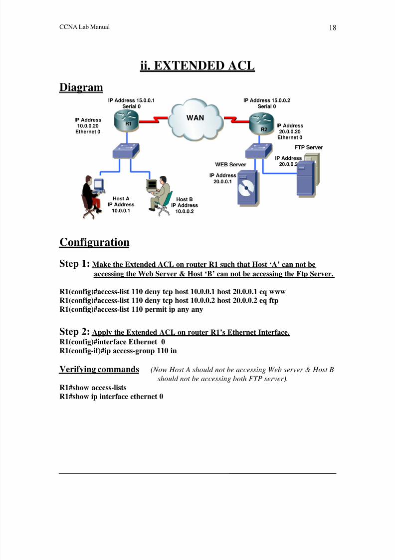
ii. EXTENDED ACL
Diagram
Configuration
Step 1: Make the Extended ACL on router R1 such that Host ‘A’ can not be
accessing the Web Server & Host ‘B’ can not be accessing the Ftp Server.
R1(config)#access-list 110 deny tcp host 10.0.0.1 host 20.0.0.1 eq wwwR1(config)#access-list 110 deny tcp host 10.0.0.2 host 20.0.0.2 eq ftp
R1(config)#access-list 110 permit ip any any
Step 2: Apply the Extended ACL on router R1’s Ethernet Interface.
R1(config)#interface Ethernet 0
R1(config-if)#ip access-group 110 in
Verifying commands (Now Host A should not be accessing Web server & Host B
should not be accessing both FTP server).
R1#show access-lists
R1#show ip interface ethernet 0
Host B
IP Address
10.0.0.2
FTP Server
IP Address
20.0.0.2 IP Address
20.0.0.1 WEB Server
Host A
IP Address
10.0.0.1
IP Address
10.0.0.20
Ethernet 0 IP Address
20.0.0.20
Ethernet 0 IP Address 15.0.0.2
Serial 0 IP Address 15.0.0.1
Serial 0 WAN
R1 R2

8/4/2019 Ccna a A
http://slidepdf.com/reader/full/ccna-a-a 21/95
CCNA Lab Manual 19
Lab # 5
Network Address Translation (NAT)
i. Static Nat
Diagram
Configuration
Step 1: Establishes Static NAT Translation between an inside local address
and an inside global address.
R1(config)#ip nat inside source static 10.0.0.1 15.0.0.11
R1(config)#ip nat inside source static 10.0.0.2 15.0.0.12
Step 2: Marks the interface as connected to the Inside Network. R1(config)#interface Ethernet 0
R1(config-if)#ip nat inside
Step 3: Marks the interface as connected to the Outside Network.
R1(config)#interface serial 0
R1(config-if)#ip nat outside
IP Address 15.0.0.1
Serial 0 IP Address 15.0.0.2
Serial 0 R1 WANIP Address 10.0.0.20
Ethernet 0 IP Address 20.0.0.20Ethernet 0
IP Address
20.0.0.1 Host B
IP Address10.0.0.2
IP Address
20.0.0.2
FTP Server
WEB Server
Inside Global Outside Global
Inside Local Outside Local
R2
NAT
Translation Table Of
R110.0.0.1 15.0.0.11
10.0.0.2 15.0.0.12
Host A
IP Address10.0.0.1

8/4/2019 Ccna a A
http://slidepdf.com/reader/full/ccna-a-a 22/95
CCNA Lab Manual 20
Verifying Command
R1#show ip nat translation
R1#debug ip nat
ii. Dynamic NAT
Diagram
Configuration
Step 1: Defines a pool of global addresses to be allocated as needed.
R1(config)#ip nat pool abc 15.0.0.41 15.0.0.45 netmask 255.0.0.0
Step 2: Defines a standard IP access list permitting those inside local addresses
that are to be translated.R1(config)#access-list 1 permit 10.0.0.0 0.255.255.255
Step 3: Establishes dynamic source translation, specifying the access list defined
in the prior step.
R1(config)#ip nat inside source list 1 pool abc
Step 4: Marks the interface as connected to the Inside Network.
R1(config)#interface Ethernet 0
R1(config-if)#ip nat inside
IP Address 15.0.0.1
Serial 0 IP Address 15.0.0.2
Serial 0 R1 WANIP Address 10.0.0.20
Ethernet 0 IP Address 20.0.0.20
Ethernet 0
IP Address
20.0.0.1 Host B
IP Address
10.0.0.2
IP Address
20.0.0.2
FTP Server
WEB Server
Inside Global Outside Global
Inside Local Outside Local
R2
Dynamic NAT
Translation Table Of R1
10.0.0.1-10.0.0.2
(15.0.0.41-15.0.0.45)
Host A
IP Address
10.0.0.1
8/4/2019 Ccna a A
http://slidepdf.com/reader/full/ccna-a-a 23/95
CCNA Lab Manual 21
Step 5: Marks the interface as connected to the Outside Network.
R1(config)#interface Serial 0
R1(config-if)#ip nat outside
Verifying Command
R1#debug ip nat
R1#show ip nat translations
R1#clear ip nat translation *
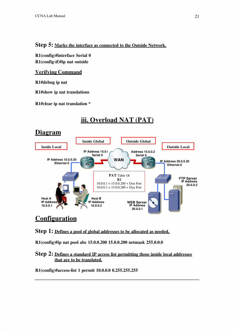
iii. Overload NAT (PAT)
Diagram
Configuration
Step 1: Defines a pool of global addresses to be allocated as needed.
R1(config)#ip nat pool abc 15.0.0.200 15.0.0.200 netmask 255.0.0.0
Step 2: Defines a standard IP access list permitting those inside local addresses
that are to be translated.
R1(config)#access-list 1 permit 10.0.0.0 0.255.255.255
IP Address 15.0.0.1
Serial 0 IP Address 15.0.0.2
Serial 0 R1 WANIP Address 10.0.0.20
Ethernet 0 IP Address 20.0.0.20
Ethernet 0
IP Address
20.0.0.1 Host B
IP Address
10.0.0.2
IP Address
20.0.0.2
FTP Server
WEB Server
Inside Global Outside Global
Inside Local Outside Local
R2
PAT Table Of
R110.0.0.1 = 15.0.0.200 + Dyn Port10.0.0.1 = 15.0.0.200 + Dyn Port
Host A
IP Address
10.0.0.1

8/4/2019 Ccna a A
http://slidepdf.com/reader/full/ccna-a-a 24/95
CCNA Lab Manual 22
Step 3: Establishes dynamic source translation, specifying the access list defined
in the prior step.
R1(config)#ip nat inside source list 1 pool abc overload
Step 4: Marks the interface as connected to the Inside Network.
R1(config)#interface Ethernet 0
R1(config-if)#ip nat inside
Step 5: Marks the interface as connected to the Outside Network.
R1(config)#interface Serial 0R1(config-if)#ip nat outside
Verifying Command
R1#debug ip nat
R1#show ip nat translations

8/4/2019 Ccna a A
http://slidepdf.com/reader/full/ccna-a-a 25/95
CCNA Lab Manual 23
Lab # 6
2950 Switch Basic Native IOSDiagram
SWA-2950
Console 0
Roll Over
Cable
Configuration
Step 1: After connecting your PC to the Console Port.
Switch con0 is now available
Press RETURN to get started.
Switch> (User Mode)
Step 2: To Enter Into Privilege mode/Executive Mode From User Mode & Vice-
Versa.
Switch>enable
Switch#
Switch#disable
Switch>
Step 3: To Enter Into Global Configuration Mode.
Switch#config t
Switch(config)#

8/4/2019 Ccna a A
http://slidepdf.com/reader/full/ccna-a-a 26/95
CCNA Lab Manual 24
Step 4: To change the Host Name of Switch.
Switch(config)#hostname 2950-SWA
2950-SWA(config)#
Step 5: Set the Message of the Day Banner
Switch(config)#banner motd # HELLO & WELCOME TO CISCO WORLD #
Step 6: Display the Version Information of the Switch.
2950-SWA#show version
Cisco Internetwork Operating System SoftwareIOS (tm) C2950 Software (C2950-I5Q3L2-M), Version 12.1(20)EA2, RELEASE
SOFTWARE(fc1)Copyright (c) 1986-2004 by cisco Systems, Inc.Compiled Wed 19-May-04 05:06 by antonino
Image text-base: 0x00003000, data-base: 0x0082D44C
ROM: Bootstrap program is C2950 boot loader
2950 uptime is 7 hours, 11 minutesSystem returned to ROM by power-on
System image file is "flash:c2950-i5q3l2-mz.121-20.EA2.bin"
cisco WS-C2950-24 (PowerPC) processor (revision L0) with 65526K/8192K bytes of memory.
Processor board ID CAT0805Z0CW
Last reset from warm-resetBridging software.
Running Layer2/3 Switching Image
Ethernet-controller 1 has 12 Fast Ethernet/IEEE 802.3 interfaces
Ethernet-controller 2 has 12 Fast Ethernet/IEEE 802.3 interfacesEthernet-controller 3 has 1 Gigabit Ethernet/IEEE 802.3 interface
Ethernet-controller 4 has 1 Gigabit Ethernet/IEEE 802.3 interface
24 FastEthernet/IEEE 802.3 interface(s)
2 Gigabit Ethernet/IEEE 802.3 interface(s)
The password-recovery mechanism is enabled.
384K bytes of flash-simulated non-volatile configuration memory.
8/4/2019 Ccna a A
http://slidepdf.com/reader/full/ccna-a-a 27/95
CCNA Lab Manual 25
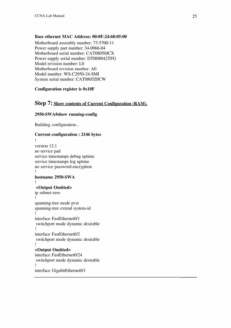
Base ethernet MAC Address: 00:0F:24:68:05:00
Motherboard assembly number: 73-5700-11
Power supply part number: 34-0966-04Motherboard serial number: CAT08050JCX
Power supply serial number: DTH08042TFGModel revision number: L0
Motherboard revision number: A0Model number: WS-C2950-24-SMI
System serial number: CAT0805Z0CW
Configuration register is 0x10F
Step 7: Show contents of Current Configuration (RAM).
2950-SWA#show running-config
Building configuration...
Current configuration : 2146 bytes
!
version 12.1no service pad
service timestamps debug uptime
service timestamps log uptimeno service password-encryption
!hostname 2950-SWA!
<Output Omitted> ip subnet-zero
!spanning-tree mode pvst
spanning-tree extend system-id
!interface FastEthernet0/1
switchport mode dynamic desirable
!interface FastEthernet0/2
switchport mode dynamic desirable
!
<Output Omitted>interface FastEthernet0/24
switchport mode dynamic desirable
!interface GigabitEthernet0/1

8/4/2019 Ccna a A
http://slidepdf.com/reader/full/ccna-a-a 28/95
CCNA Lab Manual 26
switchport mode dynamic desirable
!
interface GigabitEthernet0/2switchport mode dynamic desirable
!interface Vlan1no ip address
shutdown!
ip classlessip http server
!
<Output Omitted> end
Step 8: Display the Flash Information.
2950-SWA#dir
OR
2950-SWA#show flash:
Directory of flash: /
2 -rwx 556 Mar 1 1993 00:18:07 +00:00 vlan.dat
3 -rwx 4219426 Mar 1 1993 00:44:10 +00:00 c2950-i5q3l2-mz.121-20.EA2.bin4 -rwx 315 Mar 1 1993 00:45:44 +00:00 system_env_vars5 -rwx 0 Mar 1 1993 00:45:43 +00:00 env_vars
8 drwx 192 Mar 1 1993 00:04:07 +00:00 c2950-i9q3l2-mz.121-14.EA1a
87 -rwx 744 Mar 1 1993 00:26:17 +00:00 debug.text
15998976 bytes total (6026752 bytes free)
Step 9: To give the IP Address of Management Domain Interface OF 2950.
2950-SWA(config)#int vlan 12950-SWA(config-if)#ip address 10.0.0.10 255.0.0.0
2950-SWA(config-if)#no shutdown
Step 10: Display the information of Management VLAN Interface.
2950-SWA#sh int vlan 1

8/4/2019 Ccna a A
http://slidepdf.com/reader/full/ccna-a-a 29/95
CCNA Lab Manual 27
Vlan1 is up, line protocol is up
Hardware is EtherSVI, address is 000f.2468.0500 (bia 000f.2468.0500)
Internet address is 10.0.0.10/8
MTU 1500 bytes, BW 1000000 Kbit, DLY 10 usec,reliability 255/255, txload 1/255, rxload 1/255
Encapsulation ARPA, loopback not set
ARP type: ARPA, ARP Timeout 04:00:00
Queueing strategy: fifo
Output queue: 0/40 (size/max)<Output Omitted>
Step 11: Display the information of All Interfaces on the switch.
2950-SWA#sh ip int brief
Interface IP-Address OK Method Status Protocol
Vlan1 10.0.0.10 YES manual up down
FastEthernet0/1 unassigned YES unset down down
FastEthernet0/2 unassigned YES unset down down
FastEthernet0/23 unassigned YES unset down down
<Output Omitted>
FastEthernet0/24 unassigned YES unset down down
GigabitEthernet0/1 unassigned YES unset down down
GigabitEthernet0/2 unassigned YES unset down down
Step 12: Set a IP Default Network In a Switched Network.
2950-SWA(config)#ip default-gateway 10.0.0.1
Step 13: Display the Status of the Interfaces on the switch.
2950-SWA#show interfaces status

8/4/2019 Ccna a A
http://slidepdf.com/reader/full/ccna-a-a 30/95
CCNA Lab Manual 28
Port Name Status Vlan Duplex Speed Type
Fa0/2 notconnect 1 auto auto 10/100BaseTX
<Output Omitted>
Fa0/22 notconnect 1 auto auto 10/100BaseTX
Fa0/23 notconnect 1 auto auto 10/100BaseTX
Fa0/24 notconnect 1 auto auto 10/100BaseTX
Gi0/1 notconnect 1 auto auto unknownGi0/2 notconnect 1 auto auto unknown
Step 14: Display the Detailed Information of Interfaces.
2950-SWA#show interfaces
OR
2950-SWA#show interfaces fastEthernet 0/1
FastEthernet0/1 is up, line protocol is up (connect)Hardware is Fast Ethernet, address is 000f.2468.0501 (bia 000f.2468.0501)MTU 1500 bytes, BW 10000 Kbit, DLY 1000 usec,
Encapsulation ARPA, loopback not set
Keepalive set (10 sec)
Auto-duplex, Auto-speed, media type is 100BaseTX
input flow-control is off, output flow-control is unsupported
ARP type: ARPA, ARP Timeout 04:00:00
Queueing strategy: fifoOutput queue: 0/40 (size/max)
5 minute input rate 0 bits/sec, 0 packets/sec5 minute output rate 0 bits/sec, 0 packets/sec
<Output Omitted>
Step 15: Display the Information of the Mode of Interfaces (Switchport).
2950-SWA#show interfaces switchport
OR
2950-SWA#show interfaces fastEthernet 0/1 switchport

8/4/2019 Ccna a A
http://slidepdf.com/reader/full/ccna-a-a 31/95
CCNA Lab Manual 29
Name: Fa0/1
Switchport: Enabled
Administrative Mode: dynamic desirable
Operational Mode: static access
Administrative Trunking Encapsulation: dot1q
Operational Trunking Encapsulation: native
Negotiation of Trunking: On
Access Mode VLAN: 1 (default)Trunking Native Mode VLAN: 1 (default)
<Output Omitted>
Trunking VLANs Enabled: ALL
Pruning VLANs Enabled: 2-1001Capture Mode DisabledCapture VLANs Allowed: ALL
Protected: false
Appliance trust: none
Step 16: Display the Detailed Information of Interfaces Capabilities.
2950-SWA#show interfaces capabilities
OR
2950-SWA#show interfaces fastEthernet 0/1 capabilities
FastEthernet0/1
Model: WS-C2950-24
Type: 10/100BaseTXSpeed: 10,100,auto
Duplex: half,full,auto
Trunk encap. type: 802.1Q,ISLTrunk mode: on,off,desirable,nonegotiate
Channel: yes
<Output Omitted>
Step 17: Display the Information of the Trunk Interfaces (Ports).
2950-SWA#show interfaces trunk
Port Mode Encapsulation Status Native vlan
Fa0/23 desirable n-802.1q trunking 1

8/4/2019 Ccna a A
http://slidepdf.com/reader/full/ccna-a-a 32/95
CCNA Lab Manual 30
Fa0/24 desirable n-802.1q trunking 1
Port Vlans allowed on trunk
Fa0/23 1-4094
Fa0/24 1-4094
Port Vlans allowed and active in management domain
Fa0/23 1-2
Fa0/24 1-2
Port Vlans in spanning tree forwarding state and not pruned
Fa0/23 1-2
Fa0/24 2
Step 18: Setting Of Speed, Duplex and Description On Interface.
2950-SWA(config)#int fastEthernet 0/1
2950-SWA(config-if)#speed 100
2950-SWA(config-if)#duplex full2950-SWA(config-if)#description Fast-Ethernet-Port-1
Step 19: Configuring the Multiple Interfaces.
2950-SWA(config)#int range fastEthernet 0/1 - 5
2950-SWA(config-if-range)#switchport mode access
Step 20: Shown the MAC Address Table Information.
2950-SWA#show mac address-table dynamicMac Address Table
-------------------------------------------
Vlan Mac Address Type Ports
----- ------------------- -------------- -----
1 0001.0262.fcc4 DYNAMIC Fa0/1Total Mac Addresses for this criterion: 1
Step 21: Display the Information of CDP (Cisco Discovery Protocol).
2950-SWA#sh cdp
Global CDP information:
Sending CDP packets every 60 seconds
Sending a holdtime value of 180 seconds

8/4/2019 Ccna a A
http://slidepdf.com/reader/full/ccna-a-a 33/95
CCNA Lab Manual 31
Sending CDPv2 advertisements is enabled
Step 22: Display the Information of CDP Enabled Interfaces.
2950-SWA#sh cdp interfaces
FastEthernet0/1 is up, line protocol is up
Encapsulation ARPA
Sending CDP packets every 60 seconds
Holdtime is 180 seconds
FastEthernet0/2 is down, line protocol is down
Encapsulation ARPA
Sending CDP packets every 60 seconds
Holdtime is 180 seconds
<OUTPUT OMITTED>
FastEthernet0/24 is up, line protocol is up
Encapsulation ARPA
Sending CDP packets every 60 seconds
Holdtime is 180 seconds
GigabitEthernet0/1 is down, line protocol is down
Encapsulation ARPA
Sending CDP packets every 60 seconds
Holdtime is 180 seconds
GigabitEthernet0/2 is down, line protocol is down
Encapsulation ARPA
Sending CDP packets every 60 seconds
Holdtime is 180 seconds
Step 23: Enabled the CDP on the switch.
Switch(config)#cdp run
Step 24: Enable CDP on the Interface FastEthernet 0/1.
Switch(config)#interface fastethernet 0/1
Switch(config-if)#cdp enable

8/4/2019 Ccna a A
http://slidepdf.com/reader/full/ccna-a-a 34/95
CCNA Lab Manual 32
Step 25(A): Set the Line Console Password on the switch.
2950-SWA(config)#line console 02950-SWA(config-line)#password cisco2950-SWA(config-line)#login
Step 25(B): Verification Line Console Password on the switch.
2950-SWA con0 is now available
Press RETURN to get started.User Access Verification
Password:2950-SWA>enable
Step 26(A): Set the privileged mode password in clear text.
2950-SWA(config)#enable password cisco
Step 27(B): Verifying the privileged mode password in clear text.
2950-SWA#disable
2950-SWA>enable
Password:
2950-SWA#
Step 28(A): Set the Privileged Mode password in encrypted form.
2950-SWA(config)#enable secret cisco
The enable secret you have chosen is the same as your enable password.
This is not recommended. Re-enter the enable secret.
2950-SWA(config)#enable secret cisco1
Step 28(B): Verifying the Privileged Mode password in encrypted form.
2950-SWA>enablePassword:
8/4/2019 Ccna a A
http://slidepdf.com/reader/full/ccna-a-a 35/95
CCNA Lab Manual 33
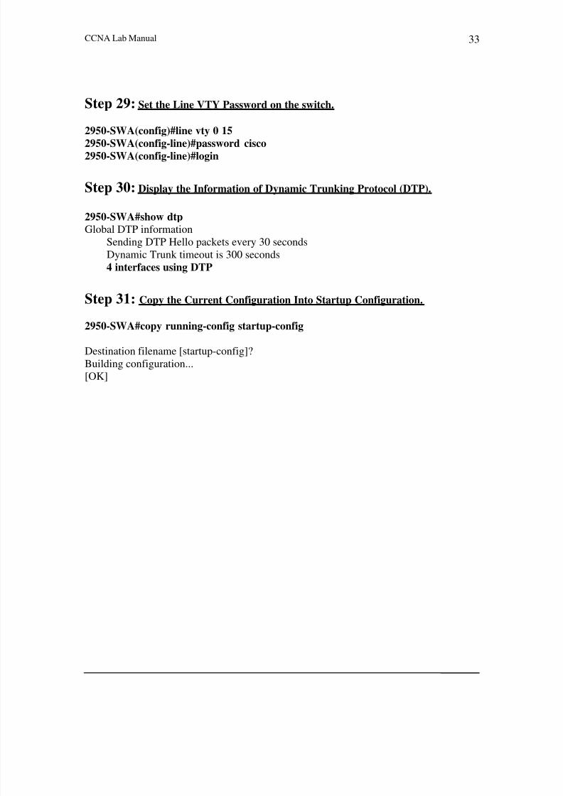
Step 29: Set the Line VTY Password on the switch.
2950-SWA(config)#line vty 0 15
2950-SWA(config-line)#password cisco2950-SWA(config-line)#login
Step 30: Display the Information of Dynamic Trunking Protocol (DTP).
2950-SWA#show dtpGlobal DTP information
Sending DTP Hello packets every 30 seconds
Dynamic Trunk timeout is 300 seconds
4 interfaces using DTP
Step 31: Copy the Current Configuration Into Startup Configuration.
2950-SWA#copy running-config startup-config
Destination filename [startup-config]?
Building configuration...
[OK]

8/4/2019 Ccna a A
http://slidepdf.com/reader/full/ccna-a-a 36/95

8/4/2019 Ccna a A
http://slidepdf.com/reader/full/ccna-a-a 37/95
CCNA Lab Manual 35
Lab # 8
VLANs
Diagram
Switch
Con 0
Configuration
Step 1: Creating vlans (VLAN # 2 & VLAN#3).
Switch(config)#vlan 2Switch(config-vlan)#name esp2
Switch(config)#vlan 3
Switch(config-vlan)#name esp3
Step 2: Deleting a vlan (VLAN # 2).
Switch(config)#no vlan 2
Step 3: Assigning Port#1 in Vlan 3.
Switch(config)#interface fastEthernet 0/1
Switch(config-if)#switchport mode access
Switch(config-if)#switchport access vlan 3
Step 4: Assigning a Range of Ports ( Port#4 – Port#6 ) in Vlan 3. Switch(config)#interface fastEthernet 0/4 - 6
Switch(config-range)#switchport mode access
Switch(config-range)#switchport access vlan 3
Verifying CommandSwitch#show vlan

8/4/2019 Ccna a A
http://slidepdf.com/reader/full/ccna-a-a 38/95
CCNA Lab Manual 36
Lab # 9
VLAN Trunking Protocol (VTP)Diagram
VTP Domain CISCO
VTP Mode: SERVER VTP Mode: CLIENT
SWA-2950 SWB-2950
Configuration
Step 1: To set the VTP Domain CISCO on the switch.
Switch(config)#vtp domain CISCOChanging VTP domain name from NULL to CISCO
Step 2: To change Operating mode of a switch in VTP domain.
Switch(config)#vtp mode ?
client Set the device to client mode.
server Set the device to server mode.
transparent Set the device to transparent mode.
Switch(config)#vtp mode client Setting device to VTP CLIENT mode.
Con 0
FastEthernet 0/ 24FastEthernet 0/24
Con 0

8/4/2019 Ccna a A
http://slidepdf.com/reader/full/ccna-a-a 39/95
CCNA Lab Manual 37
Step 3: Enable Trunking on the fastEthernet ports 0/24 of switch.
Switch(config)#int fastEthernet 0/24Switch(config-if)#switchport mode trunk
Verifying Command
Switch# show vtp status
Switch#show vlan

8/4/2019 Ccna a A
http://slidepdf.com/reader/full/ccna-a-a 40/95
CCNA Lab Manual 38
Lab # 10
PPP AUTHENTICATION- CHAP
Diagram
Configuration
IP Address 15.0.0.1
Serial 0 IP Address 15.0.0.2
Serial 0 R2 R1
WAN
Step 1(A): Change the Hostname to R1 & Assign the IP addresses on the SerialInterface of Router R1 as shown in figure.
Step 1(B): Change the Hostname to R2 & Assign the IP addresses on the Serial
Interface of Router R2 as shown in figure.
Step 2(A): CHAP Authentication Configuration for Router R1.
R1(config)#username R2 password cisco123R1(config)#interface serial 0
R1(config-if)#encapsulation pppR1(config-if)#ppp authentication chap
Step 2(B): CHAP Authentication Configuration for Router R2.
R2(config)#username R1 password cisco123
R2(config)#interface serial 0R2(config-if)#encapsulation ppp
R2(config-if)#ppp authentication chap
Verifying Commands
Router#show interfaces serial 0
Router#debug ppp authentication

8/4/2019 Ccna a A
http://slidepdf.com/reader/full/ccna-a-a 41/95
CCNA Lab Manual 39
Lab # 11
FRAME RELAY-(Point-to-Point) Diagram
Configuration
Step 1: Configuring the FR switch.
FR-SWITCH(config)#frame-relay switching
FR-SWITCH(config)#int s0FR-SWITCH(config-if)#no ip address
FR-SWITCH(config-if)#no shutdown
FR-SWITCH(config-if)#encapsulation frame-relayFR-SWITCH(config-if)#frame-relay intf-type dce
FR-SWITCH(config-if)#clock rate 64000
FR-SWITCH(config-if)#frame-relay route 102 int s1 201
FR-SWITCH(config)#int s1
FR-SWITCH(config-if)#no ip address
FR-SWITCH(config-if)#no shutdownFR-SWITCH(config-if)#encapsulation frame-relay
FR-SWITCH(config-if)#frame-relay intf-type dce
FR-SWITCH(config-if)#clock rate 64000FR-SWITCH(config-if)#frame-relay route 201 int s0 102
DLCI=102
Frame Relay Network
(FR Switch)
Serial 0 Serial 1DCE DCE
IP Address 15.0.0.2Serial 0
DTE
IP Address 15.0.0.1Serial 0
DTE
R1 DLCI=201 R2
Frame Relay Frame Relay Client Client

8/4/2019 Ccna a A
http://slidepdf.com/reader/full/ccna-a-a 42/95
CCNA Lab Manual 40
Step 2(A): Assigning the IP addresses to the FR Client Router R1.
R1(config)#interface serial 0
R1(config-if)#ip address 15.0.0.1 255.0.0.0R1(config-if)#no shutdownR1(config-if)#encapsulation frame-relay
Step 2(B): Assigning the IP addresses to the FR Client Router R2.
R2(config)#interface serial 0R2(config-if)#ip address 15.0.0.2 255.0.0.0
R2(config-if)#no shutdown
R2(config-if)#encapsulation-frame-relay
Verifying Commands
FR Client
Router#show frame-relay pvcRouter#show frame-relay map
Router#show frame-relay lmi
FR Switch
Router#show frame-relay route

8/4/2019 Ccna a A
http://slidepdf.com/reader/full/ccna-a-a 43/95
CCNA Lab Manual 41
Lab # 12
WIRELESS NETWORK
i. Infrastructure Mode
Diagram
At Machine 192.168.1.4:
First configure the Access Point.
Go to the Internet Explorer and type ‘http://192.168.1.1’ in address bar.
Wireless
Client
192.168.1.3192.168.1.2
192.168.1.4 Wireless
Access Point
192.168.1.1
Wired Client

8/4/2019 Ccna a A
http://slidepdf.com/reader/full/ccna-a-a 44/95
CCNA Lab Manual 42
Go to Setup & Configure the A.P step by step.
Type the ‘Linksys’ in the SSID

8/4/2019 Ccna a A
http://slidepdf.com/reader/full/ccna-a-a 45/95
CCNA Lab Manual 43
Press “Save Settings”button
8/4/2019 Ccna a A
http://slidepdf.com/reader/full/ccna-a-a 46/95
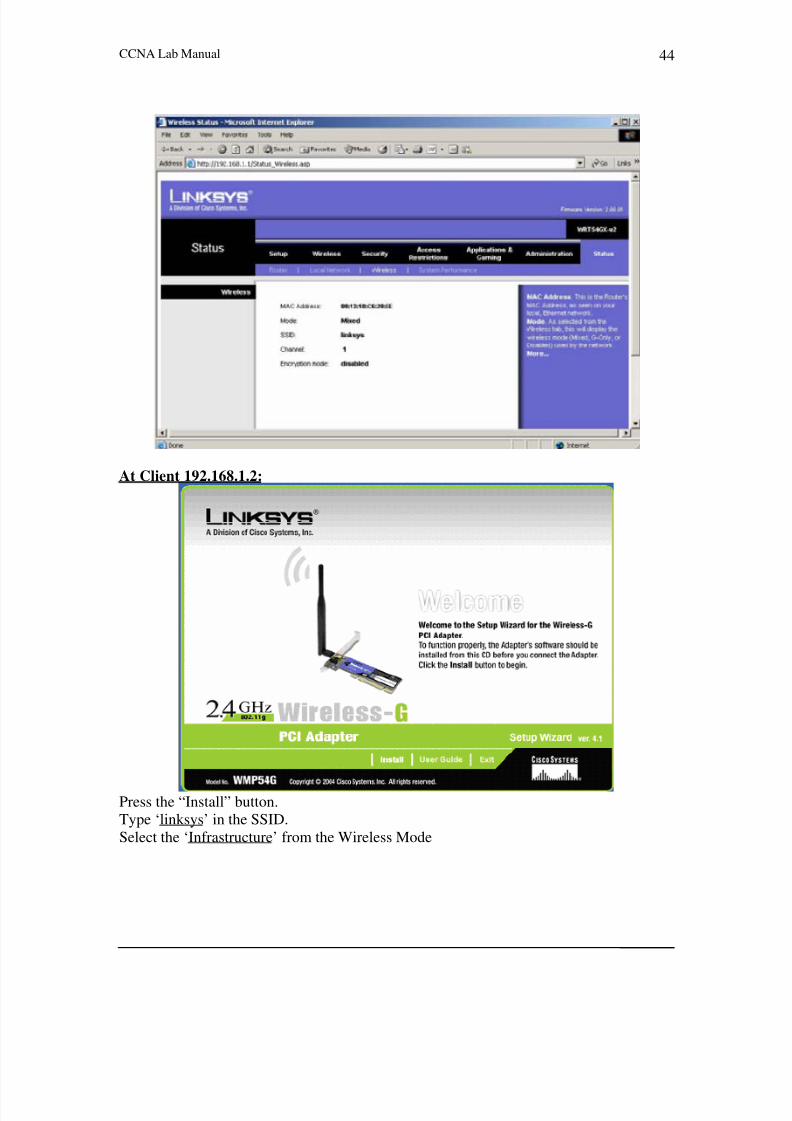
CCNA Lab Manual 44
At Client 192.168.1.2:
Press the “Install” button.
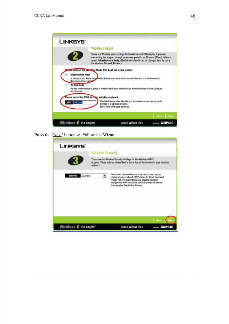
Type ‘linksys’ in the SSID.
Select the ‘Infrastructure’ from the Wireless Mode
8/4/2019 Ccna a A
http://slidepdf.com/reader/full/ccna-a-a 47/95
CCNA Lab Manual 45
Press the ‘Next’ button & Follow the Wizard

8/4/2019 Ccna a A
http://slidepdf.com/reader/full/ccna-a-a 48/95
CCNA Lab Manual 46

8/4/2019 Ccna a A
http://slidepdf.com/reader/full/ccna-a-a 49/95
CCNA Lab Manual 47
ii. Adhoc-Mode
Wireless
Adhoc-Mode
192.168.1.2 Wireless 192.168.1.3
Peer-to-Peer
Client
At Client 192.168.1.2:
Go to the LINKSYS G Wireless Utility at the task bar.
Press the configuration on the less side of LAN Monitor
Go to the Profile Tag & Follow the Wizard.

8/4/2019 Ccna a A
http://slidepdf.com/reader/full/ccna-a-a 50/95
CCNA Lab Manual 48
Select the ‘Ad-hoc’ in the Wireless Mode
Type ‘My Network’ in the SSID.

8/4/2019 Ccna a A
http://slidepdf.com/reader/full/ccna-a-a 51/95
CCNA Lab Manual 49
After completing the Wizard Follow these steps:

8/4/2019 Ccna a A
http://slidepdf.com/reader/full/ccna-a-a 52/95
CCNA Lab Manual 50
Repeat the same procedure at machine ‘192.168.1.3’.
Go to the Internet Explorer and type other machine’s ip now both machines
communicates in the Ad-hoc mode or you can ping from the command prompt by justgoing into the command prompt and type ‘ping other machine’s ip’.

8/4/2019 Ccna a A
http://slidepdf.com/reader/full/ccna-a-a 53/95
CCNA Lab Manual 51
Lab # 13
IP PHONES
Diagram
IP Address15.0.0.1
IP Address15.0.0.2
Serial 0 Serial 0
Client 2Analog Phone With
ATAIP Address
10.0.0.2 R2
WAN IP Address10.0.0.20
IP Address20.0.0.20
R1 Client 2
Analog Phone With
ATAIP Address
20.0.0.2
Client 1 Client 1IP Address
10.0.0.1 IP Address20.0.0.1

8/4/2019 Ccna a A
http://slidepdf.com/reader/full/ccna-a-a 54/95
CCNA Lab Manual 52
Appendix
8/4/2019 Ccna a A
http://slidepdf.com/reader/full/ccna-a-a 55/95
CCNA Lab Manual 53
Network Fundamentals
Ethernet Cables
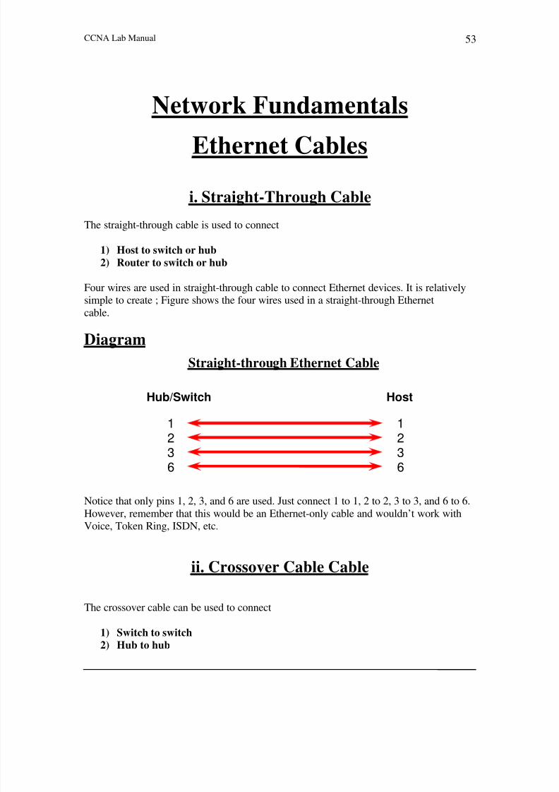
i. Straight-Through Cable
The straight-through cable is used to connect
1) Host to switch or hub
2) Router to switch or hub
Four wires are used in straight-through cable to connect Ethernet devices. It is relativelysimple to create ; Figure shows the four wires used in a straight-through Ethernet
cable.
Diagram
Straight-through Ethernet Cable
Hub/Switch Host
11
22
33
6 6
Notice that only pins 1, 2, 3, and 6 are used. Just connect 1 to 1, 2 to 2, 3 to 3, and 6 to 6.
However, remember that this would be an Ethernet-only cable and wouldn’t work withVoice, Token Ring, ISDN, etc.
ii. Crossover Cable Cable
The crossover cable can be used to connect
1) Switch to switch
2) Hub to hub

8/4/2019 Ccna a A
http://slidepdf.com/reader/full/ccna-a-a 56/95
CCNA Lab Manual 54
3) Host to host
4) Hub to switch
5) Router direct to host
The same four wires are used in this cable as in the straight-through cable; we justconnect different pins together. Figure shows how the four wires are used in a crossoverEthernet cable.
Notice that instead of connecting 1 to 1, etc., here we connect pins 1 to 3 and 2 to 6 on
each side of the cable.
Diagram
Cross-over Ethernet Cable
Hub/Switch/Host Hub/Switch/Host
1 1
2 2
3 3
6 6
iii. Rolled Cable
Although rolled cable isn’t used to connect any Ethernet connections together, you can
use a rolled Ethernet cable to connect a host to a router console serial communication(com) port.
Eight wires are used in this cable to connect serial devices, although not all eight are used
to send information, just as in Ethernet networks. Figure shows the eight wires used in arolled cable.

8/4/2019 Ccna a A
http://slidepdf.com/reader/full/ccna-a-a 57/95
CCNA Lab Manual 55
Diagram
Rolled Ethernet Cable
Host Router/Switch
1
To make, just cut the one side like a straight-through cable and reverse the other end.
Once you connect the cable from your PC to the Cisco router or switch, you can start
HyperTerminal to create a console connection and configure the device
1
22
33
44
55
66
7
8
7
8

8/4/2019 Ccna a A
http://slidepdf.com/reader/full/ccna-a-a 58/95
CCNA Lab Manual 56
How to Create A LANi. Connecting 2 PC’s via Cross Cable
Diagram
Cross Cable
Host A Host B
IP Address: 10.0.0.1 IP Address: 10.0.0.2
MAC: 00.01.02.62.fc.3b MAC: 02.00.01.e1.db.2c
ii. Connecting 2 PC’s via Straight Cable
Diagram
Straight Straight
Cable Cable
Fast Ethernet 0/1 Fast Ethernet 0/1
Host A Host B
IP Address: 10.0.0.1 IP Address: 10.0.0.2MAC: 00.01.02.62.fc.3b MAC: 02.00.01.e1.db.2c
Procedure
1. Make sure that both NICs are installed onto your PC’s.
2. Assign IP address to your LAN (NIC) card on both PC’s.

8/4/2019 Ccna a A
http://slidepdf.com/reader/full/ccna-a-a 59/95
CCNA Lab Manual 57
3. Check their connectivity by PING command & DATA sharing.
Configuration
Step 1: Make sure that both NICs are installed onto your PC’s.
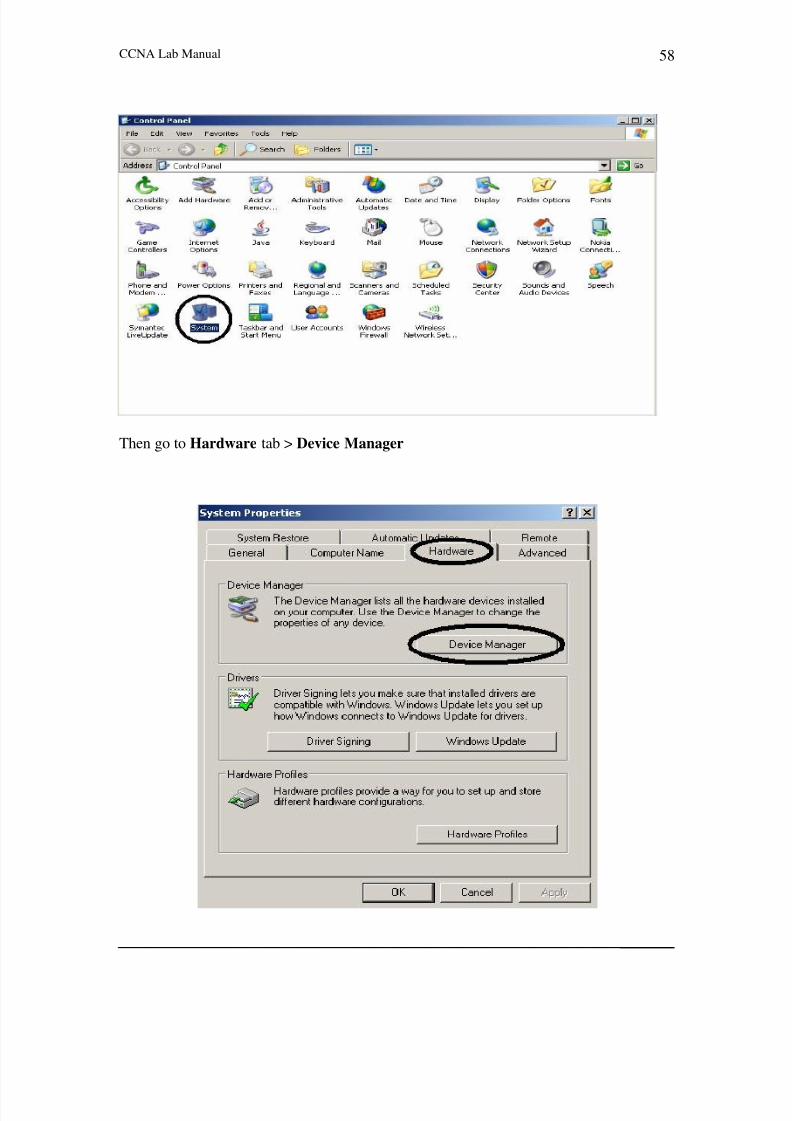
Go to Windows Start Button > Settings > Control Panel
Then go to System
8/4/2019 Ccna a A
http://slidepdf.com/reader/full/ccna-a-a 60/95
CCNA Lab Manual 58
Then go to Hardware tab > Device Manager

8/4/2019 Ccna a A
http://slidepdf.com/reader/full/ccna-a-a 61/95
CCNA Lab Manual 59
Expand the SERVER (Computer Name) tab > Network Adapters
Note: - If LAN (NIC) card is not installed onto your PC then go to Windows Start
Button > Settings > Control Panel > Add/Remove Hardware.

8/4/2019 Ccna a A
http://slidepdf.com/reader/full/ccna-a-a 62/95
CCNA Lab Manual 60
Step 2: Assign IP address to your LAN (NIC) card on both PC’s.
Go to My Network Places, Right Click & take the Properties & open the Network &
Dial-up Connections
Choose your LAN card, & take the Properties,

8/4/2019 Ccna a A
http://slidepdf.com/reader/full/ccna-a-a 63/95
CCNA Lab Manual 61
Go to the TCP/IP, & take the Properties

8/4/2019 Ccna a A
http://slidepdf.com/reader/full/ccna-a-a 64/95
CCNA Lab Manual 62
Give the IP Address, & press O.K.
Check the IP Address on the Command Prompt.
D:\>ipconfig
Windows 2000 IP Configuration
Ethernet adapter Local Area Connection:
Connection-specific DNS Suffix . :
IP Address . . . . . . . . . . . . . . : 10.0.0.1
Subnet Mask . . . . . . . . . . . : 255.0.0.0Default Gateway . . . . . . . . . :
Step 3(A): Check their connectivity by PING command.
D:\>ping 10.0.0.2
Pinging 10.0.0.2 with 32 bytes of data:
Reply from 10.0.0.2: bytes=32 time<10ms TTL=128

8/4/2019 Ccna a A
http://slidepdf.com/reader/full/ccna-a-a 65/95
CCNA Lab Manual 63
Reply from 10.0.0.2: bytes=32 time<10ms TTL=128
Reply from 10.0.0.2: bytes=32 time<10ms TTL=128
Reply from 10.0.0.2: bytes=32 time<10ms TTL=128
Ping statistics for 10.0.0.2:Packets: Sent = 4, Received = 4, Lost = 0 (0% loss),
Approximate round trip times in milli-seconds:
Minimum = 0ms, Maximum = 0ms, Average = 0ms
Step 3(B): Check their connectivity by Data Sharing.
Type on RUN as: \\10.0.0.2
The following screen will pop-up,

8/4/2019 Ccna a A
http://slidepdf.com/reader/full/ccna-a-a 66/95
CCNA Lab Manual 64

8/4/2019 Ccna a A
http://slidepdf.com/reader/full/ccna-a-a 67/95
CCNA Lab Manual 65
How to Make a Web & Ftp ServerDiagram
Procedure
1. Open an Internet Information Service (IIS) from an Administrative tools and
Make a WEB Server.2. Open an Internet Information Service (IIS) from an Administrative tools and
Make a FTP Server.
3. Verifying the WEB & FTP Derver from Host ‘A’.
Configuration
Step 1: Open an Internet Information Service (IIS) from an Administrative tools
& Make a WEB Server.
Go to Windows Start Button > Programs > Administrative Tools > Internet Services
Manager.

8/4/2019 Ccna a A
http://slidepdf.com/reader/full/ccna-a-a 68/95
CCNA Lab Manual 66
Then, Start IIS & Right Click on the Computer Name > New > Web Site

8/4/2019 Ccna a A
http://slidepdf.com/reader/full/ccna-a-a 69/95
CCNA Lab Manual 67
Start the Web Server Wizard

8/4/2019 Ccna a A
http://slidepdf.com/reader/full/ccna-a-a 70/95
CCNA Lab Manual 68
Give the Name to Web Server
Then, Set the IP Address & Port

8/4/2019 Ccna a A
http://slidepdf.com/reader/full/ccna-a-a 71/95
CCNA Lab Manual 69
Enter the Path of the Web Page
Assigns the Permission,

8/4/2019 Ccna a A
http://slidepdf.com/reader/full/ccna-a-a 72/95
CCNA Lab Manual 70
Wizard will finish now successfully.
Take the Properties of the Web Server

8/4/2019 Ccna a A
http://slidepdf.com/reader/full/ccna-a-a 73/95
CCNA Lab Manual 71
Go to the Documents tab,

8/4/2019 Ccna a A
http://slidepdf.com/reader/full/ccna-a-a 74/95
CCNA Lab Manual 72
Add your Web Page,

8/4/2019 Ccna a A
http://slidepdf.com/reader/full/ccna-a-a 75/95
CCNA Lab Manual 73
Check the Web Page by Right Click & Press the Browse.

8/4/2019 Ccna a A
http://slidepdf.com/reader/full/ccna-a-a 76/95
CCNA Lab Manual 74
Step 2: Open an Internet Information Service (IIS) from an Administrative tools& Make a FTP Server.
Go to Windows Start Button > Programs > Administrative Tools > Internet Services
Manager.

8/4/2019 Ccna a A
http://slidepdf.com/reader/full/ccna-a-a 77/95
CCNA Lab Manual 75
Then, Start IIS & Right Click on the Computer Name > New > Ftp Site

8/4/2019 Ccna a A
http://slidepdf.com/reader/full/ccna-a-a 78/95
CCNA Lab Manual 76
Start the Ftp Server Wizard

8/4/2019 Ccna a A
http://slidepdf.com/reader/full/ccna-a-a 79/95
CCNA Lab Manual 77
Give the Name to Ftp Server
Give the IP Address & Port setting

8/4/2019 Ccna a A
http://slidepdf.com/reader/full/ccna-a-a 80/95
CCNA Lab Manual 78
Enter the Path of the Ftp site
Assign the Permissions

8/4/2019 Ccna a A
http://slidepdf.com/reader/full/ccna-a-a 81/95
CCNA Lab Manual 79
Wizard will finish now successfully.
Check the Ftp Site by Right Click on Ftp Server & Press the Browse.

8/4/2019 Ccna a A
http://slidepdf.com/reader/full/ccna-a-a 82/95
CCNA Lab Manual 80
Check the Ftp Site by Right Click on Ftp Server & Press the Browse.
Step 3: Verifying the WEB & FTP Server from Host ‘A’.
WEB Server from Host ‘A’.

8/4/2019 Ccna a A
http://slidepdf.com/reader/full/ccna-a-a 83/95
CCNA Lab Manual 81
FTP Server from Host ‘A’.

8/4/2019 Ccna a A
http://slidepdf.com/reader/full/ccna-a-a 84/95
CCNA Lab Manual 82
Open A Hyper Terminal Session
Diagram
Router
Procedure
1. Open the Hyper Terminal Session From RUN by giving the command
‘hypertrm’ or from STRART Button -> Programs -> Accessories ->
Communications -> Hyper Terminal.
2. Give the Session name.
3. Define the connection type i-e., COM1.
Configuration
Step 1: Open the Hyper Terminal Session From RUN by giving the command
‘hypertrm’ or from START Button -> Programs -> Accessories ->
Communications -> Hyper Terminal.
Console 0
Roll Over
Cable
Switch
Console 0
Roll Over
Cable
Host BHost A
8/4/2019 Ccna a A
http://slidepdf.com/reader/full/ccna-a-a 85/95
CCNA Lab Manual 83
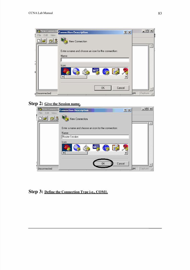
Step 2: Give the Session name.
Step 3: Define the Connection Type i-e., COM1.

8/4/2019 Ccna a A
http://slidepdf.com/reader/full/ccna-a-a 86/95
CCNA Lab Manual 84
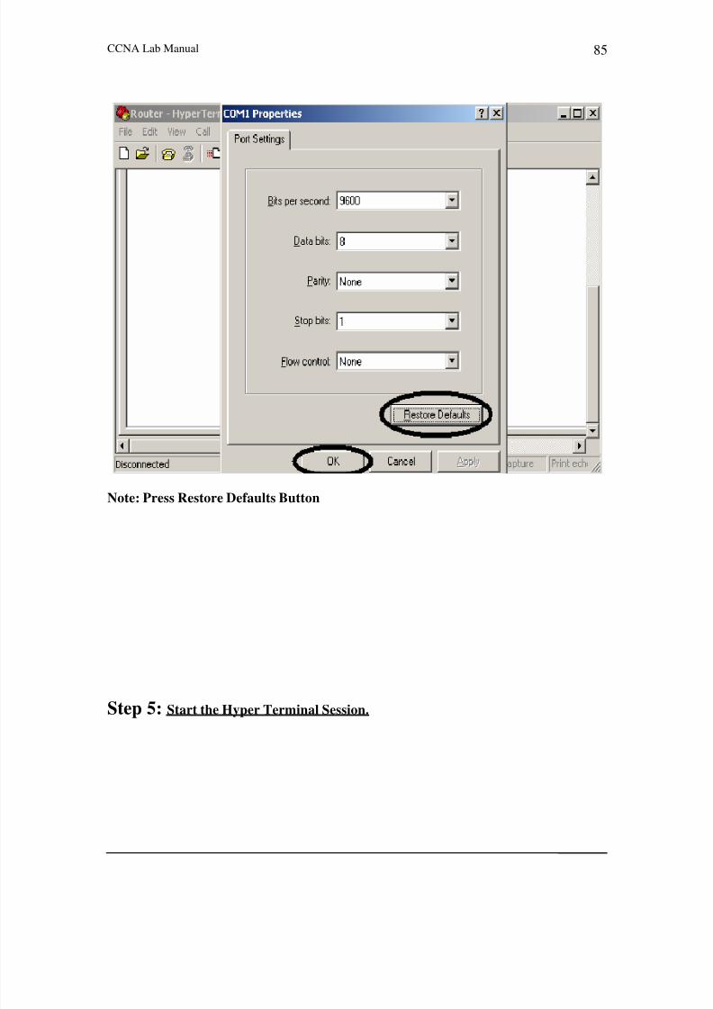
Step 4: Define the Port Settings of COM Port.
8/4/2019 Ccna a A
http://slidepdf.com/reader/full/ccna-a-a 87/95
CCNA Lab Manual 85
Note: Press Restore Defaults Button
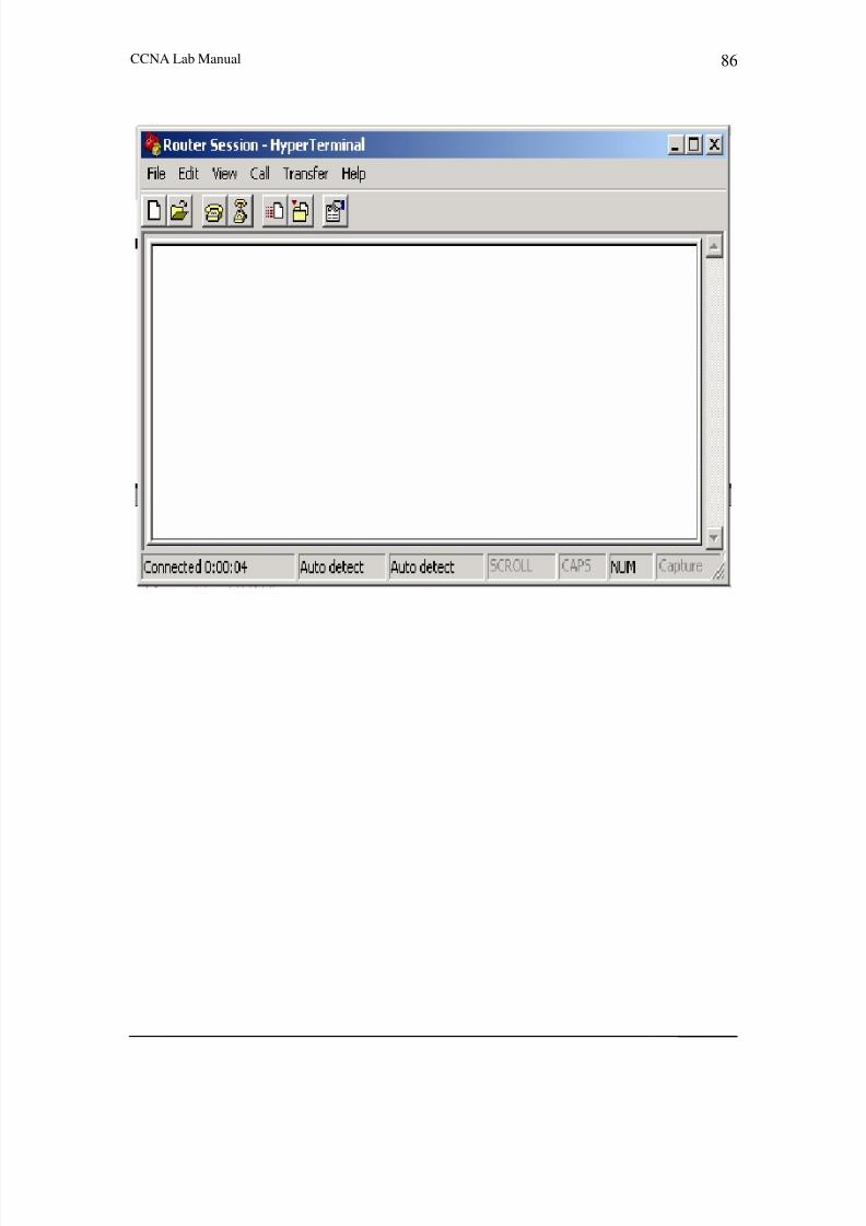
Step 5: Start the Hyper Terminal Session.
8/4/2019 Ccna a A
http://slidepdf.com/reader/full/ccna-a-a 88/95
CCNA Lab Manual 86

8/4/2019 Ccna a A
http://slidepdf.com/reader/full/ccna-a-a 89/95
CCNA Lab Manual 87
Password Recovery
Diagram
Router
Console 0
Roll Over Cable
Procedure
1. Attach a PC with terminal emulation software to the Router’s Console port.
2. Turn off the Router, and turn it on and press the Break Key on the PC within 60
seconds of turning on the Router.3. Enter the command to By-Pass the NVRAM on the > prompt and initialize the
Router by command.
4. Enter no in response to the System Configuration dialog prompts.5. Enter into the Router and copy the configuration from the NVRAM, change the
password & change the value of the configuration register & save the
configuration into NVRAM again and reload the Router.
Configuration
Step 1: Attach a PC with terminal emulation software to the Router’s Console
Port.

8/4/2019 Ccna a A
http://slidepdf.com/reader/full/ccna-a-a 90/95
CCNA Lab Manual 88
The configuration register value is 0x2102 by-default. It’s mean that whenever the Router
boots, it will read the contents of the NVRAM. So, we need to by-pass the NVRAM at
the time of startup for the password recovery.
Step 2: Turn off the Router, and turn it on and press the Break Key on the PCwithin 60 seconds of turning on the Router.
The > prompt with no Router name appears at the Router screen.
Step 3: Enter the command to By-Pass the NVRAM on the > prompt and
initialize the Router by command.
> o/r 0x2142 (to boot from flash)
> i (initialize the Router)
Step 4: Enter no in response to the System Configuration dialog prompts until the
following message appears.
Press RETURN to get started!
Step 5: Enter into the Router and copy the configuration from the NVRAM,
change the password & change the value of the configuration register &
save the configuration into NVRAM again and reload the Router.
Router#copy stratup-config running-config
Router(config)#no enable passwordRouter(config)#enable password cisco
Router(config)#configuration-register 0x2102Router#write memory (Equivalent Command of copy running-config startup-config)
Router#reload

8/4/2019 Ccna a A
http://slidepdf.com/reader/full/ccna-a-a 91/95
CCNA Lab Manual 89
TFTP Server
i. Uploading Configuration from Router to the TFTP
Server
Diagram
Uploading Configuration
Procedure
1. Make a TFTP Server to Host ‘A’.
2. Verification of connectivity of PC & Router by ping command.3. Upload the NVRAM Configuration into TFTP Server.
4. Verifying the uploaded configuration from the TFTP Server.

8/4/2019 Ccna a A
http://slidepdf.com/reader/full/ccna-a-a 92/95
CCNA Lab Manual 90
Configuration
Step 1: Make a TFTP Server to Host ‘A’.
tep 2: Verification of connectivity of PC & Switch by ping command.S
1#ping 10.0.0.1
ype escape sequence to abort.s to 10.0.0.1, timeout is 2 seconds:
ss rate is 100 percent (5/5), round-trip min/avg/max = 1/2/4 ms
tep 3: Upload the NVRAM Configuration into TFTP Server.
R
TSending 5, 100-byte ICMP Echo
!!!!!
Succe
S
g tftp
emote host []? 10.0.0.1
e to write [r1-confg]? R1-configuration
R1#copy startup-confi
R
Name of configuration fil
Write file R1-configuration on host 10.0.0.1? [confirm]
Writing R1-configuration !! [OK]

8/4/2019 Ccna a A
http://slidepdf.com/reader/full/ccna-a-a 93/95
CCNA Lab Manual 91
Step 4: Verifying the uploaded configuration from the TFTP Server.
ii. Downloading Configuration to Router from the TFTP
Server
Diagram

8/4/2019 Ccna a A
http://slidepdf.com/reader/full/ccna-a-a 94/95
CCNA Lab Manual 92
Procedure
1.2.
3.
4.
5.6.
Make a TFTP Server to Host ‘A’.Remove the Configuration from the NVRAM and reload the Router.
Give the IP Address to the Router.
Verification of connectivity of PC & Router by ping command.
Download the NVRAM Configuration from the TFTP Server.Verifying the uploaded configuration from the TFTP Server.
ConfigurationMake a TFTP Server to Host ‘A’.Step 1:
onfigu ation from the NVRAM & reload the Router.
Step 2: Remove the C r
R1#write erase[OK]
R1#reload
Proceed with reload? [confirm]
%SYS-5-RELOAD: Reload requestedSystem Bootstrap, Version 11.0(10c), SOFTWARE
Copyright (c) 1986-1996 by cisco Systems
<Output Omitted>
Step 3: Give the IP Address to the Router.
Router(config)#int ethernet 0
Router(config-if)#ip address 10.0.0.20 255.0.0.0

8/4/2019 Ccna a A
http://slidepdf.com/reader/full/ccna-a-a 95/95
CCNA Lab Manual 93
Step 4: Verification of connectivity of PC & Switch by ping command.
Router#ping 10.0.0.1
Type escape sequence to abort.Sending 5, 100-byte ICMP Echos to 10.0.0.1, timeout is 2 seconds:.!!!!
Success rate is 80 percent (4/5), round-trip min/avg/max = 1/3/4 ms
Step 5: Download the NVRAM Configuration from TFTP Server.
Router#copy tftp running-config
Host or network configuration file [host]?
Address of remote host [255.255.255.255]? 10.0.0.1
Name of configuration file [router-confg]? R1-configurationonfigure using R1-configuration from 10.0.0.1? [confirm]
: Configured from R1-configuration by console tftp from 10.0.0.1
): Verifying the uploaded configuration by the command.
C
Loading R1-configuration from 10.0.0.1 (via Ethernet0): !
[OK - 1076/32723 bytes]R1#%SYS-5-CONFIG
Step 6(A
m the TFTP Server.
R1#show running-config
figuration froStep 6(B): Verifying the uploaded con