Embed Size (px)
Citation preview

7/29/2019 CCNA LEC 2
http://slidepdf.com/reader/full/ccna-lec-2 1/44

7/29/2019 CCNA LEC 2
http://slidepdf.com/reader/full/ccna-lec-2 2/44

7/29/2019 CCNA LEC 2
http://slidepdf.com/reader/full/ccna-lec-2 3/44
Why Another Model?
Although the OSI reference model is universally recognized, thehistorical and technical open standard of the Internet isTransmission Control Protocol / Internet Protocol (TCP/IP).
The TCP/IP reference model and the TCP/IP protocol stack make data communication possible between any two
computers, anywhere in the world, at nearly the speed of light.
The U.S. Department of Defense (DoD) created the TCP/IPreference model because it wanted a network that could survive
any conditions, even a nuclear war.

7/29/2019 CCNA LEC 2
http://slidepdf.com/reader/full/ccna-lec-2 4/44
TCP/IP Protocol Stack
7
6
5
4
3
2
5
4
3
2
Application
Presentation
Session
Transport
Network
Data-Link
Physical 1
Application
Transport
Internet
Data-Link
Physical 1

7/29/2019 CCNA LEC 2
http://slidepdf.com/reader/full/ccna-lec-2 5/44
Application Layer Overview
*Used by the Router
Application
Transport
Internet
Data-Link
Physical
File Transfer- TFTP*- FTP*- NFS
E-Mail- SMTP
Remote Login- Telnet*- rlogin*
Network Management- SNMP*
Name Management- DNS*

7/29/2019 CCNA LEC 2
http://slidepdf.com/reader/full/ccna-lec-2 6/44
Transport Layer Overview
Transmission ControlProtocol (TCP)
User DatagramProtocol (UDP)
Application
Transport
Internet
Data-Link
Physical
Connection-Oriented
Connectionless

7/29/2019 CCNA LEC 2
http://slidepdf.com/reader/full/ccna-lec-2 7/44

7/29/2019 CCNA LEC 2
http://slidepdf.com/reader/full/ccna-lec-2 8/44
Decimal to Binary
100 = 1101 = 10102 = 100
103 = 1000
1
10
100
1000
172 – Base 10
1
24
8
16
32
64
128
10101100 –
Base 2
20 = 121 = 2
22
= 423 = 824 = 1625 = 3226 = 6427 = 128
10101100
172
270
100
172
0
0480
320
128
172

7/29/2019 CCNA LEC 2
http://slidepdf.com/reader/full/ccna-lec-2 9/44
Base 2 Number System
101102 = (1 x 24 = 16) + (0 x 23 = 0) + (1 x 22 = 4) +
(1 x 21 = 2) + (0 x 20 = 0) = 22

7/29/2019 CCNA LEC 2
http://slidepdf.com/reader/full/ccna-lec-2 10/44
IP Addressing
255 255 255 255
DottedDecimal
Maximum
Network Host
1
2 8
6 4
3 2
1 6 8 4 2 1
11111111 11111111 11111111 11111111
10101100 00010000 01111010 11001100
Binary
32 Bits
172 16 122 204ExampleDecimal
Example
Binary
1 8 9 16 17 24 25 32
1
2 8
6 4
3 2
1 6 8 4 2 1
1
2 8
6 4
3 2
1 6 8 4 2 1
1
2 8
6 4
3 2
1 6 8 4 2 1
7/29/2019 CCNA LEC 2
http://slidepdf.com/reader/full/ccna-lec-2 11/44
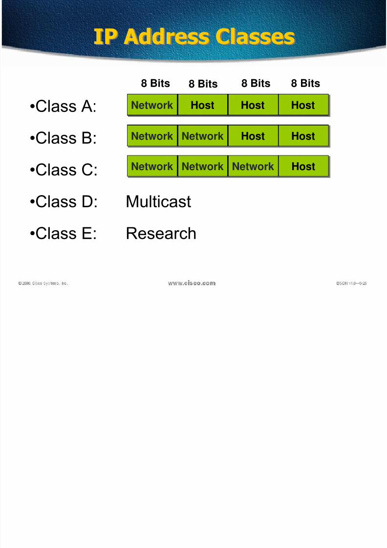
•Class A:
•Class B:
•Class C:
•Class D: Multicast
•Class E: Research
IP Address Classes
Network Host Host Host
Network Network Host Host
Network Network Network Host
8 Bits 8 Bits 8 Bits 8 Bits
7/29/2019 CCNA LEC 2
http://slidepdf.com/reader/full/ccna-lec-2 12/44
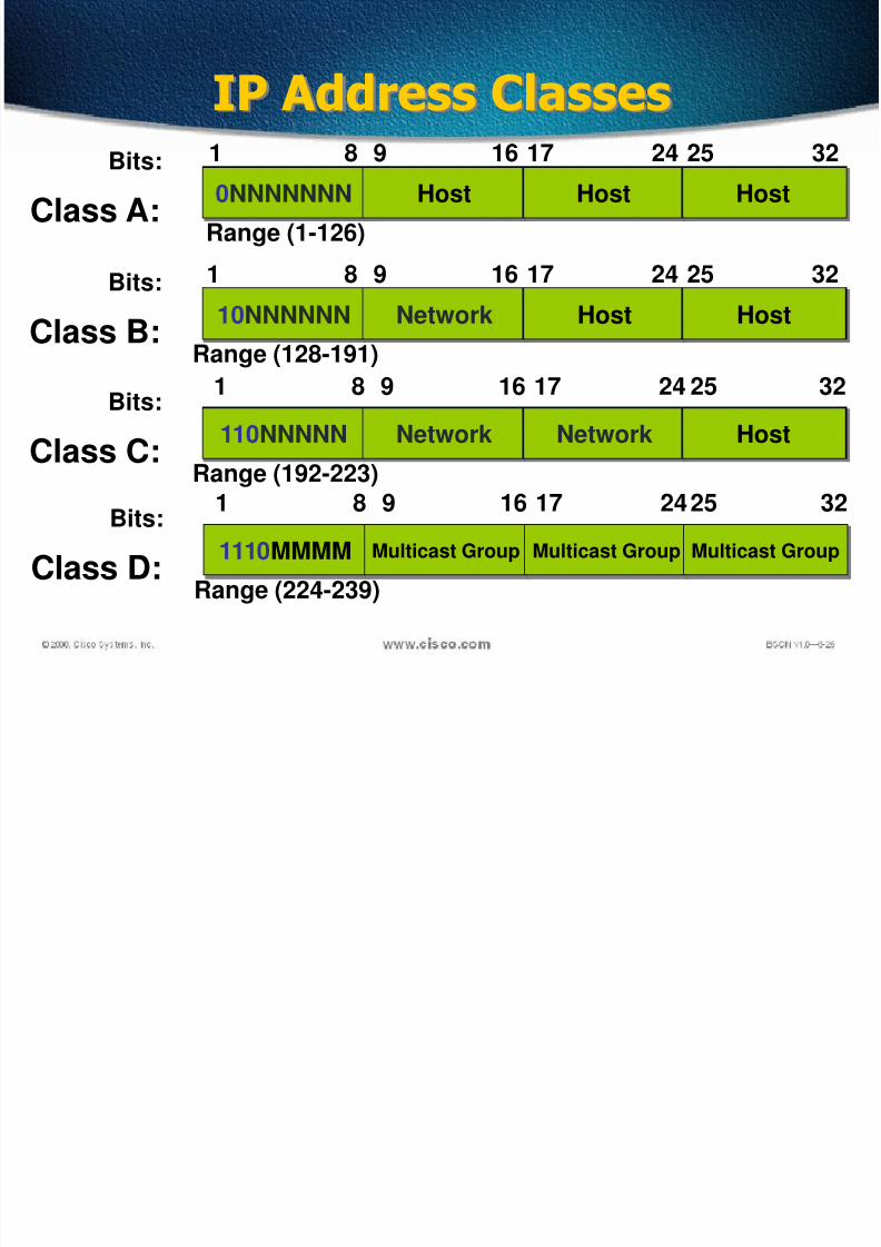
IP Address Classes
1
Class A:
Bits:0NNNNNNN Host Host Host
8 9 16 17 24 25 32
Range (1-126)
1
Class B:
Bits:
10NNNNNN Network Host Host
8 9 16 17 24 25 32
Range (128-191)
1
Class C:
Bits:
110NNNNN Network Network Host
8 9 16 17 24 25 32
Range (192-223)
1
Class D:
Bits:
1110MMMM Multicast Group Multicast Group Multicast Group
8 9 16 17 24 25 32
Range (224-239)

7/29/2019 CCNA LEC 2
http://slidepdf.com/reader/full/ccna-lec-2 13/44
Host Addresses
172.16.2.2
172.16.3.10
172.16.12.12
10.1.1.1
10.250.8.11
10.180.30.118
E1
172.16 12 12
Network Host
. . Network Interface
172.16.0.0
10.0.0.0
E0
E1
Routing Table
172.16.2.1
10.6.24.2
E0

7/29/2019 CCNA LEC 2
http://slidepdf.com/reader/full/ccna-lec-2 14/44
VLSM
• VLSM is a method of designating a different subnet
mask for the same network number on different subnets
•
Can use a long mask on networks with few hosts and ashorter mask on subnets with many hosts
• With VLSMs we can have different subnet masks for
different subnets.

7/29/2019 CCNA LEC 2
http://slidepdf.com/reader/full/ccna-lec-2 15/44
Variable Length Subnetting
VLSM allows us to use one class C address todesign a networking scheme to meet thefollowing requirements:
Bangalore 60 HostsMumbai 28 Hosts
Sydney 12 Hosts
Singapore 12 Hosts
WAN 1 2 Hosts
WAN 2 2 Hosts
WAN 3 2 Hosts
7/29/2019 CCNA LEC 2
http://slidepdf.com/reader/full/ccna-lec-2 16/44
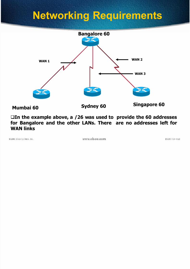
Networking Requirements
Bangalore 60
Mumbai 60 Sydney 60 Singapore 60
WAN 1WAN 2
WAN 3
In the example above, a /26 was used to provide the 60 addressesfor Bangalore and the other LANs. There are no addresses left forWAN links

7/29/2019 CCNA LEC 2
http://slidepdf.com/reader/full/ccna-lec-2 17/44
Networking Scheme
Mumbai 192.168.10.64/27
Bangalore192.168.10.0/26
Sydney 192.168.10.96/28
Singapore 192.168.10.112/28
WAN 192.168.10.129 and 130 WAN 192.198.10.133 and 134
WAN 192.198.10.137 and 138
60 12 12
28
22
2192.168.10.128/30
192.168.10.136/30
192.168.10.132/30
7/29/2019 CCNA LEC 2
http://slidepdf.com/reader/full/ccna-lec-2 18/44
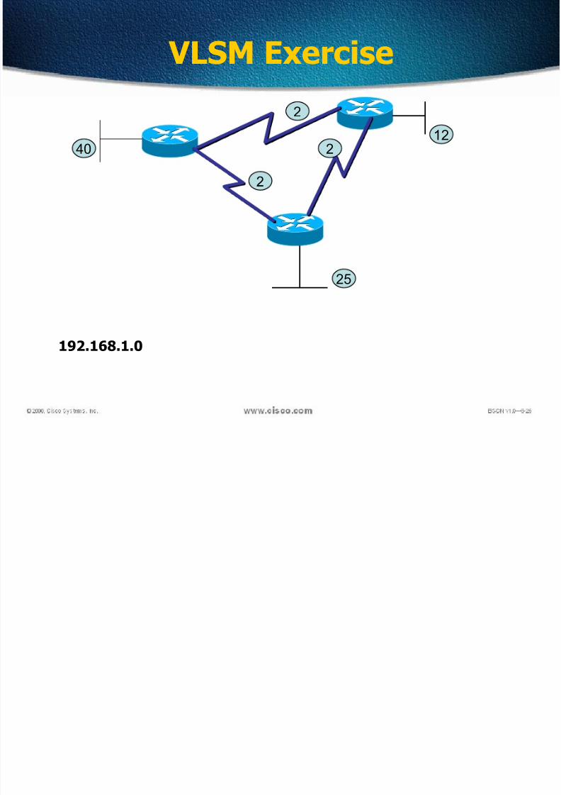
VLSM Exercise
2
2
2
40
25
12
192.168.1.0

7/29/2019 CCNA LEC 2
http://slidepdf.com/reader/full/ccna-lec-2 19/44
VLSM Exercise
22
2
40
25
12
192.168.1.0
192.168.1.4/30
192.168.1.8/30
192.168.1.12/30
192.168.1.16/28
192.168.1.32/27
192.168.1.64/26

7/29/2019 CCNA LEC 2
http://slidepdf.com/reader/full/ccna-lec-2 20/44
VLSM Exercise
2
2
8
15
5
192.168.1.0
2
235

7/29/2019 CCNA LEC 2
http://slidepdf.com/reader/full/ccna-lec-2 21/44
Summarization
• Summarization, also called route aggregation, allowsrouting protocols to advertise many networks as oneaddress.
• The purpose of this is to reduce the size of routing tableson routers to save memory
• Route summarization (also called route aggregation orsupernetting) can reduce the number of routes that arouter must maintain
• Route summarization is possible only when a properaddressing plan is in place
• Route summarization is most effective within asubnetted environment when the network addresses arein contiguous blocks

7/29/2019 CCNA LEC 2
http://slidepdf.com/reader/full/ccna-lec-2 22/44
Summarization

7/29/2019 CCNA LEC 2
http://slidepdf.com/reader/full/ccna-lec-2 23/44
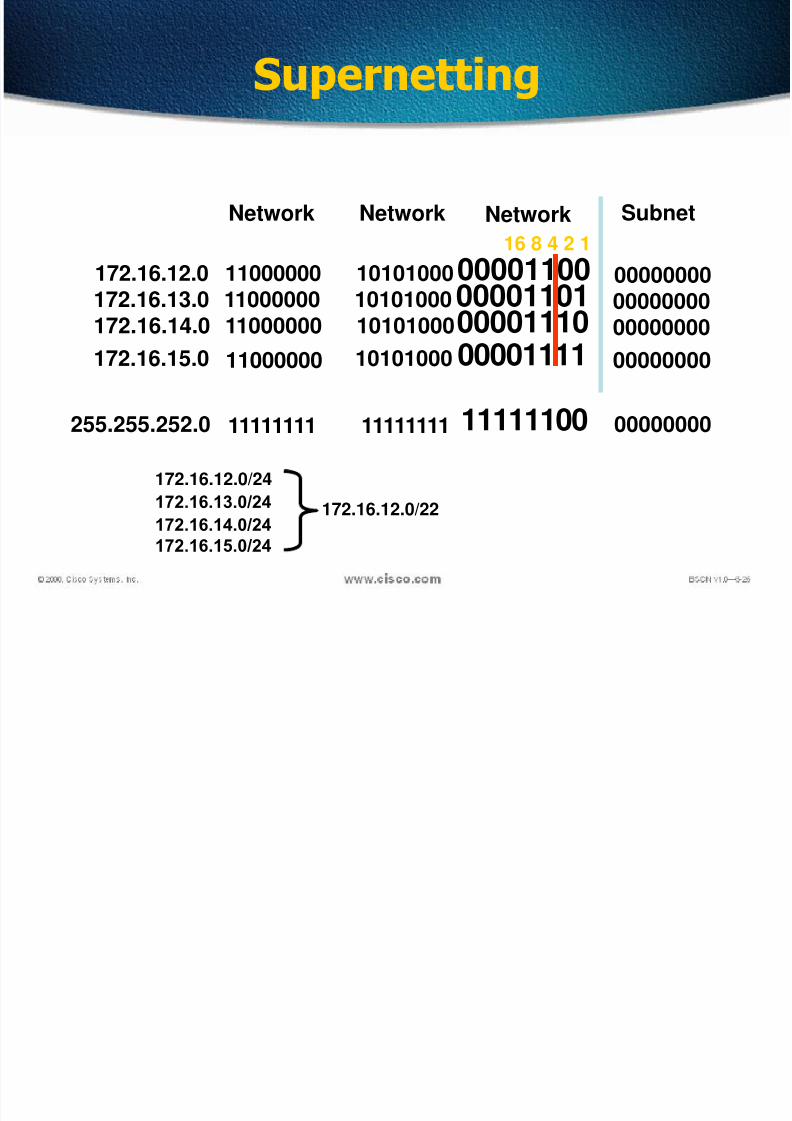
Supernetting
Network Subnet
172.16.12.0 11000000
11111111
10101000
11111111
00001100
11111111 255.255.255.0
NetworkNetwork
00000000
00000000
16 8 4 2 1
172.16.13.0 11000000 1010100000001101 00000000172.16.14.0 11000000 10101000 00001110 00000000
172.16.15.0 11000000 10101000 00001111 00000000
7/29/2019 CCNA LEC 2
http://slidepdf.com/reader/full/ccna-lec-2 24/44
Supernetting
Network Subnet
172.16.12.0 11000000
11111111
10101000
11111111
00001100
11111100 255.255.252.0
NetworkNetwork
00000000
00000000
16 8 4 2 1
172.16.13.0 11000000 1010100000001101 00000000172.16.14.0 11000000 10101000 00001110 00000000
172.16.15.0 11000000 10101000 00001111 00000000
172.16.12.0/24
172.16.13.0/24
172.16.14.0/24
172.16.15.0/24
172.16.12.0/22

7/29/2019 CCNA LEC 2
http://slidepdf.com/reader/full/ccna-lec-2 25/44
Supernetting Question
What is the most efficient summarization that TK1 can use to advertise itsnetworks to TK2?
A. 172.1.4.0/24172.1.5.0/24172.1.6.0/24172.1.7.0/24B. 172.1.0.0/22C. 172.1.4.0/25172.1.4.128/25172.1.5.0/24172.1.6.0/24172.1.7.0/24D. 172.1.0.0/21E. 172.1.4.0/22

7/29/2019 CCNA LEC 2
http://slidepdf.com/reader/full/ccna-lec-2 26/44

7/29/2019 CCNA LEC 2
http://slidepdf.com/reader/full/ccna-lec-2 27/44
Network Topologies
Network topology defines the structure of the network.
One part of the topology definition is the physical topology,
which is the actual layout of the wire or media.
The other part is the logical topology,which defines how the
media is accessed by the hosts for sending data.

7/29/2019 CCNA LEC 2
http://slidepdf.com/reader/full/ccna-lec-2 28/44
Bus Topology
A bus topology uses a single backbone cable that isterminated at both ends.
All the hosts connect directly to this backbone.

7/29/2019 CCNA LEC 2
http://slidepdf.com/reader/full/ccna-lec-2 29/44
Ring Topology
A ring topology connects one host to the next and the last
host to the first.
This creates a physical ring of cable.

7/29/2019 CCNA LEC 2
http://slidepdf.com/reader/full/ccna-lec-2 30/44
Star Topology
A star topology connects all cables to a central point of concentration.

7/29/2019 CCNA LEC 2
http://slidepdf.com/reader/full/ccna-lec-2 31/44
Extended Star Topology
An extended star topology links individual stars together byconnecting the hubs and/or switches.This topology can extendthe scope and coverage of the network.

7/29/2019 CCNA LEC 2
http://slidepdf.com/reader/full/ccna-lec-2 32/44
Mesh Topology
A mesh topology is implemented to provide as muchprotection as possible from interruption of service.Each host has its own connections to all other hosts. Although the Internet has multiple paths to any one
location, it does not adopt the full mesh topology.

7/29/2019 CCNA LEC 2
http://slidepdf.com/reader/full/ccna-lec-2 33/44
Institute of Electrical and ElectronicsEngineers (IEEE) 802 Standards
IEEE 802.1: Standards related to network management.
IEEE 802.2: General standard for the data link layer in the OSIReference Model. The IEEE divides this layer into two sublayers --the logical link control (LLC) layer and the media access control(MAC) layer.
IEEE 802.3: Defines the MAC layer for bus networks that useCSMA/CD. This is the basis of the Ethernet standard.
IEEE 802.4: Defines the MAC layer for bus networks that use a
token-passing mechanism (token bus networks).
IEEE 802.5: Defines the MAC layer for token-ring networks.
IEEE 802.6: Standard for Metropolitan Area Networks (MANs)

7/29/2019 CCNA LEC 2
http://slidepdf.com/reader/full/ccna-lec-2 34/44
Found by Xerox Palo Alto Research Center (PARC) in1975
Original designed as a 2.94 Mbps system to connect100 computers on a 1 km cable
Later, Xerox, Intel and DEC drew up a standardsupport 10 Mbps – Ethernet II
Basis for the IEEE’s 802.3 specification
Most widely used LAN technology in the world
Origin of Ethernet
7/29/2019 CCNA LEC 2
http://slidepdf.com/reader/full/ccna-lec-2 35/44
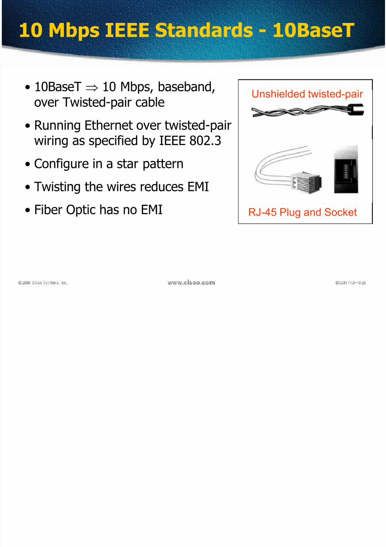
10 Mbps IEEE Standards - 10BaseT
• 10BaseT 10 Mbps, baseband,over Twisted-pair cable
• Running Ethernet over twisted-pair
wiring as specified by IEEE 802.3
• Configure in a star pattern
• Twisting the wires reduces EMI
• Fiber Optic has no EMI
Unshielded twisted-pair
RJ-45 Plug and Socket

7/29/2019 CCNA LEC 2
http://slidepdf.com/reader/full/ccna-lec-2 36/44
Unshielded Twisted Pair Cable (UTP)most popularmaximum length 100 m
prone to noise
Category 1
Category 2
Category 3Category 4
Category 5
Category 6
Voice transmission of traditional telephone
For data up to 4 Mbps, 4 pairs full-duplex
For data up to 10 Mbps, 4 pairs full-duplexFor data up to 16 Mbps, 4 pairs full-duplex
For data up to 100 Mbps, 4 pairs full-duplex
For data up to 1000 Mbps, 4 pairs full-duplex
Twisted Pair Cables

7/29/2019 CCNA LEC 2
http://slidepdf.com/reader/full/ccna-lec-2 37/44
Baseband Transmission Entire channel is used to transmit a single digital signal Complete bandwidth of the cable is used by a single signal The transmission distance is shorter The electrical interference is lower
Broadband Transmission Use analog signaling and a range of frequencies Continuous signals flow in the form of waves Support multiple analog transmission (channels)
Modem Broadband
Transmission
Network
Card
Baseband
Transmission
Baseband VS Broadband

7/29/2019 CCNA LEC 2
http://slidepdf.com/reader/full/ccna-lec-2 38/44
Straight-through cable

7/29/2019 CCNA LEC 2
http://slidepdf.com/reader/full/ccna-lec-2 39/44
Straight-through cable pinout

7/29/2019 CCNA LEC 2
http://slidepdf.com/reader/full/ccna-lec-2 40/44
Crossover cable

7/29/2019 CCNA LEC 2
http://slidepdf.com/reader/full/ccna-lec-2 41/44
Crossover cable

7/29/2019 CCNA LEC 2
http://slidepdf.com/reader/full/ccna-lec-2 42/44
Rollover cable

7/29/2019 CCNA LEC 2
http://slidepdf.com/reader/full/ccna-lec-2 43/44
Rollover cable pinout

7/29/2019 CCNA LEC 2
http://slidepdf.com/reader/full/ccna-lec-2 44/44
Straight-Thru or Crossover
Use straight-through cables for the following cabling: Switch to router Switch to PC or server Hub to PC or server
Use crossover cables for the following cabling: Switch to switch Switch to hub
Hub to hub Router to router PC to PC Router to PC