Embed Size (px)
Citation preview
Test Report
Product Name : Notebook PC
Model No. : MS-1461
Marketing Name : X410
Applicant : Micro-Star Int’L Co., Ltd.
Address : No. 69, Li-De St., Chung-Ho City, Taipei Hsien, Taiwan
Date of Receipt : 2009/06/01
Issued Date : 2009/06/22
Report No. : 096S040-RF-CE-P02V01
Report Version. : V1.0
The test results relate only to the samples tested.The test results shown in the test report are traceable to the national/international standard through the calibration of the equipment and evaluated measurement uncertainty herein. This report must not be used to claim product endorsement by CNLA, NVLAP, NIST or any agency of the Government. The test report shall not be reproduced except in full without the written approval of QuieTek Corporation.

Report No: 096S040-RF-CE-P02V01
Page: 2 of 159
Test Report Cert i f icat ion Issued Date : 2009/06/22 Report No. : 096S040-RF-CE-P02V01
Product Name : Notebook PC
Applicant : Micro-Star Int’L Co., Ltd.
Address : No. 69, Li-De St., Chung-Ho City, Taipei Hsien, Taiwan
Manufacturer : MSI ELECTRONICS (KUNGSHAN) CO., LTD.
Model No. : MS-1461
Marketing Name : X410
Rated Voltage : AC 230 V / 50 Hz
EUT Voltage : AC 100-240 V / 50-60 Hz
Trade Name : msi
Applicable Standard : ETSI EN 301 489-1 V1.8.1 (2008-04)
ETSI EN 301 489-17 V1.3.2 (2008-04)
Test Result : Complied
Performed Location : SuZhou EMC laboratory
No.99 Hongye Rd., Suzhou Industrial Park Loufeng
Hi-Tech Development Zone., SuZhou, China
TEL: +86-512-6251-5088 / FAX: +86-512-6251-5098
Documented By :
( Any Liu )
Reviewed By :
( Coffon Ye )
Approved By :
( Gene Zhang )

Report No: 096S040-RF-CE-P02V01
Page: 3 of 159
Laboratory Information
We , QuieTek Corporation, are an independent EMC and safety consultancy that was established the whole facility in our laboratories. The test facility has been accredited by the following accreditation Bodies in compliance with ISO 17025, EN 45001 and Guide 25:
The related certificate for our laboratories about the test site and management system can be downloaded from QuieTek Corporation’s Web Site : http://tw.quietek.com/modules/myalbum/ The address and introduction of QuieTek Corporation’s laboratories can be founded in our Web site : http://www.quietek.com/ If you have any comments, Please don’t hesitate to contact us. Our contact information is as below: HsinChu Testing Laboratory :
No.75-2, 3rd Lin, Wangye Keng, Yonghxing Tsuen, Qionglin Shiang, Hsinchu County 307, Taiwan, R.O.C. TEL:+886-3-592-8858 / FAX:+886-3-592-8859 E-Mail : [email protected]
LinKou Testing Laboratory :
No. 5, Ruei-Shu Valley, Ruei-Ping Tsuen, Lin-Kou Shiang, Taipei, Taiwan, R.O.C. TEL : +886-2-8601-3788 / FAX : 886-2-8601-3789 E-Mail : [email protected]
Suzhou Testing Laboratory : No.99 Hongye Rd., Suzhou Industrial Park Loufeng Hi-Tech Development Zone., SuZhou, China
TEL : +86-512-6251-5088 / FAX : 86-512-6251-5098 E-Mail : [email protected]
Taiwan R.O.C. : BSMI, DGT, CNLA
Germany : TUV Rheinland
Norway : Nemko, DNV
USA : FCC, NVLAP
Japan : VCCI
Report No: 096S040-RF-CE-P02V01
Page: 4 of 159
TABLE OF CONTENTS Description Page 1. General Information .......................................................................................................8 1.1. EUT Description.........................................................................................................8 1.2. Mode of Operation.....................................................................................................9 1.3. Tested System Details .............................................................................................10 1.4. Configuration of Tested System............................................................................... 11 1.5. EUT Exercise Software............................................................................................12 2. Technical Test ..............................................................................................................13 2.1. Summary of Test Result...........................................................................................13 2.2. List of Test Equipment .............................................................................................14 2.3. Measurement Uncertainty........................................................................................14 2.4. Test Environment .....................................................................................................19 2.5. Performance criteria ................................................................................................21 3. Conducted Emission (AC input/output Ports)...............................................................24 3.1. Test Specification.....................................................................................................24 3.2. Test Setup................................................................................................................24 3.3. Limit………. .............................................................................................................24 3.4. Test Procedure ........................................................................................................25 3.5. Deviation from Test Standard...................................................................................25 3.6. Test Result...............................................................................................................26 3.7. Test Photograph ......................................................................................................38 4. Conducted Emission (DC input/output Ports) ..............................................................39 4.1. Test Specification.....................................................................................................40 4.2. Test Setup................................................................................................................40 4.3. Limit……..................................................................................................................40 4.4. Test Procedure ........................................................................................................41 4.5. Deviation from Test Standard...................................................................................41 4.6. Test Result...............................................................................................................41 5. Conducted Emissions (Telecommunication Ports).......................................................42 5.1. Test Specification.....................................................................................................42 5.2. Test Setup................................................................................................................42 5.3. Limit….. ...................................................................................................................42 5.4. Test Procedure ........................................................................................................43 5.5. Deviation from Test Standard...................................................................................43 5.6. Test Result...............................................................................................................44 5.7. Test Photograph ......................................................................................................56 6. Radiated Emission.......................................................................................................57
Report No: 096S040-RF-CE-P02V01
Page: 5 of 159
6.1. Test Specification.....................................................................................................58 6.2. Test Setup................................................................................................................58 6.3. Limit………. .............................................................................................................59 6.4. Test Procedure ........................................................................................................60 6.5. Deviation from Test Standard...................................................................................61 6.6. Test Result...............................................................................................................62 6.7. Test Photograph ......................................................................................................74 7. Harmonic Current Emission .........................................................................................76 7.1. Test Specification.....................................................................................................78 7.2. Test Setup................................................................................................................78 7.3. Limit……..................................................................................................................78 7.4. Test Procedure ........................................................................................................80 7.5. Deviation from Test Standard...................................................................................80 7.6. Test Result...............................................................................................................81 7.7. Test Photograph ......................................................................................................85 8. Voltage Fluctuation and Flicker....................................................................................86 8.1. Test Specification.....................................................................................................86 8.2. Test Setup................................................................................................................86 8.3. Limit………. .............................................................................................................86 8.4. Test Procedure ........................................................................................................87 8.5. Deviation from Test Standard...................................................................................87 8.6. Test Result...............................................................................................................88 8.7. Test Photograph ......................................................................................................90 9. Electrostatic Discharge ................................................................................................90 9.1. Test Specification.....................................................................................................91 9.2. Test Setup................................................................................................................91 9.3. Limit………. .............................................................................................................91 9.4. Test Procedure ........................................................................................................92 9.5. Deviation from Test Standard...................................................................................92 9.6. Test Result...............................................................................................................93 9.7. Test Photograph ......................................................................................................97 10. RF Electromagnetic Field..............................................................................................98 10.1. Test Specification.....................................................................................................99 10.2. Test Setup ...............................................................................................................99 10.3. Limit……… ..............................................................................................................99 10.4. Test Procedure ......................................................................................................100 10.5. Deviation from Test Standard ................................................................................100 10.6. Test Result.............................................................................................................101

Report No: 096S040-RF-CE-P02V01
Page: 6 of 159
10.7. Test Photograph ....................................................................................................105 11. Fast Transients Common Mode ..................................................................................107 11.1. Test Specification...................................................................................................107 11.2. Test Setup..............................................................................................................107 11.3. Limit………. ...........................................................................................................107 11.4. Test Procedure.......................................................................................................108 11.5. Deviation from Test Standard.................................................................................108 11.6. Test Result .............................................................................................................109 11.7. Test Photograph..................................................................................................... 113 12. Surges……….............................................................................................................. 117 12.1. Test Specification................................................................................................... 117 12.2. Test Setup ............................................................................................................. 117 12.3. Limit………. ........................................................................................................... 117 12.4. Test Procedure ...................................................................................................... 118 12.5. Deviation from Test Standard ................................................................................ 118 12.6. Test Result............................................................................................................. 119 12.7. Test Photograph ....................................................................................................123 13. RF Common Mode......................................................................................................124 13.1. Test Specification...................................................................................................125 13.2. Test Setup .............................................................................................................125 13.3. Limit……….. ..........................................................................................................126 13.4. Test Procedure ......................................................................................................126 13.5. Deviation from Test Standard ................................................................................127 13.6. Test Result.............................................................................................................128 13.7. Test Photograph ....................................................................................................132 14. Voltage Dips and Interruption......................................................................................136 14.1. Test Specification...................................................................................................136 14.2. Test Setup .............................................................................................................136 14.3. Limit……................................................................................................................136 14.4. Test Procedure ......................................................................................................137 14.5. Deviation from Test Standard ................................................................................137 14.6. Test Result.............................................................................................................138 14.7. Test Photograph ....................................................................................................146 15. Transients and surges.................................................................................................147 15.1. Test Specification...................................................................................................148 15.2. Test Setup .............................................................................................................148 15.3. Limit……................................................................................................................148 15.4. Test Procedure ......................................................................................................148

Report No: 096S040-RF-CE-P02V01
Page: 7 of 159
15.5. Deviation from Test Standard ................................................................................149 15.6. Test Result.............................................................................................................149 16. Attachment ..................................................................................................................150 EUT Photograph...........................................................................................................150
Report No: 096S040-RF-CE-P02V01
Page: 8 of 159
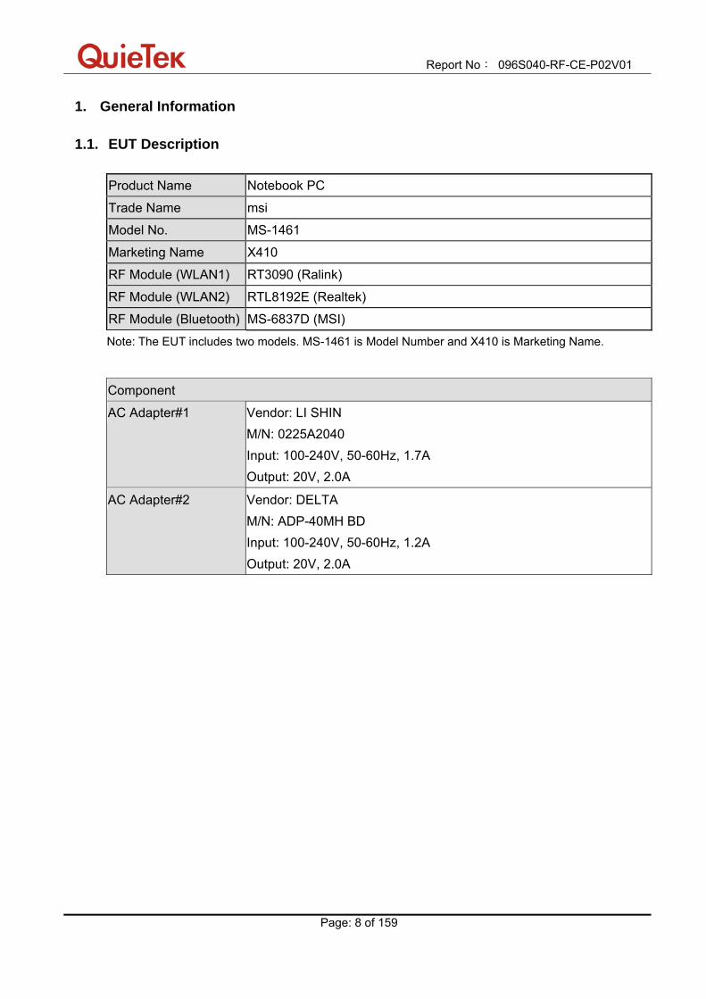
1. General Information 1.1. EUT Description
Product Name Notebook PC
Trade Name msi
Model No. MS-1461
Marketing Name X410
RF Module (WLAN1) RT3090 (Ralink)
RF Module (WLAN2) RTL8192E (Realtek)
RF Module (Bluetooth) MS-6837D (MSI)
Note: The EUT includes two models. MS-1461 is Model Number and X410 is Marketing Name.
Component
AC Adapter#1 Vendor: LI SHIN M/N: 0225A2040 Input: 100-240V, 50-60Hz, 1.7A Output: 20V, 2.0A
AC Adapter#2 Vendor: DELTA M/N: ADP-40MH BD Input: 100-240V, 50-60Hz, 1.2A Output: 20V, 2.0A

Report No: 096S040-RF-CE-P02V01
Page: 9 of 159
1.2. Mode of Operation QuieTek has verified the construction and function in typical operation. All the test modes were carried out with the EUT in normal operation, which was shown in this test report and defined as:
Pre-Test Mode
Mode 1: Communication by WLAN1 and Bluetooth Mode 2: Standby Mode 3: Communication by WLAN2 and Bluetooth Mode 4: Standby
Final Test Mode
EMI Mode 1: Communication by WLAN1 and Bluetooth Mode 3: Communication by WLAN2 and Bluetooth
EMS
Mode 1: Communication by WLAN1 and Bluetooth Mode 2: Standby Mode 3: Communication by WLAN2 and Bluetooth Mode 4: Standby

Report No: 096S040-RF-CE-P02V01
Page: 10 of 159
1.3. Tested System Details The types for all equipments, plus descriptions of all cables used in the tested system (including inserted cards) are:
Product Manufacturer Model No. Serial No. Power Cord
1 CRT ‘’21 IBM 6652-U3N 1 Non-Shielded, 1.8m
2 LCD Monitor DELL 3008WFPT 7735432490P08B Non-Shielded, 1.8m
3 iPod Apple A1199 YM715J43VQ5 Power by PC
4 USB Mouse DELL MO56UOA F1B03EZZ Power by PC
5 Microphone & Earphone SOMIC SM-510 N/A N/A
6 SD Card Kingston 1GB N/A N/A
7 MacBook Apple MB061CH W8732B4TZ5V Power by adapter

Report No: 096S040-RF-CE-P02V01
Page: 11 of 159
1.4. Configuration of Tested System
Connection Diagram
Signal Cable Type Signal cable Description A VGA Cable Shielded, 1.8m, with two ferrite cores Bonded B HDMI Cable Shielded, 1.8m C USB Cable Shielded, 1.0m D USB Mouse Cable Shielded, 1.8m E Earphone & Microphone Cable Non-Shielded, 2.1m F LAN Cable Non-Shielded, >10m

Report No: 096S040-RF-CE-P02V01
Page: 12 of 159
1.5. EUT Exercise Software
1 Setup the EUT and simulators as shown above.
2 Turn on the power of all equipment.
3 Execute the HDD running Program using BurnIn Test v5.1 software.
4 Run EMC test program using BurnIn Test v5.1 software and send “H” pattern to the monitor.
5 EUT will send and receive data through LAN using “Ping” function.
6 Communicate with another notebook by WLAN and Bluetooth.
7 Open the camera and play music using media player program.

Report No: 096S040-RF-CE-P02V01
Page: 13 of 159
2. Technical Test 2.1. Summary of Test Result
No deviations from the test standards Deviations from the test standards as below description:
Emission
Performed Test Item Normative References Test
Performed Deviation
Conducted Emission
(AC input/output Ports)
EN 55022: 2006+A1: 2007 Class B Yes No
Conducted Emissions
(DC input/output Ports)
EN 55022: 2006+A1: 2007 Class B
CISPR 25: 2002
N/A N/A
Conducted Emissions
(Telecommunication Ports)
EN 55022: 2006+A1: 2007 Class B Yes No
Radiated Emission EN 55022: 2006+A1: 2007 Class B Yes No
Harmonic Current Emission EN 61000-3-2: 2006 Yes No
Voltage Fluctuations and Flicker EN 61000-3-3: 1995+A1: 2001+A2: 2005 Yes No
Immunity
Performed Test Item Normative References Test
Performed Deviation
Electrostatic Discharge EN 61000-4-2: 2001 Yes No
RF Electromagnetic Field EN 61000-4-3: 2006 Yes No
Fast Transients Common Mode EN 61000-4-4: 2004 Yes No
Surges EN 61000-4-5: 2006 Yes No
RF Common Mode EN 61000-4-6: 2005 Yes No
Voltage Dips and Interruption EN 61000-4-11: 2004 Yes No
Transients and Surges ISO 7637-2: 2004 N/A N/A

Report No: 096S040-RF-CE-P02V01
Page: 14 of 159
2.2. List of Test Equipment Conducted Emission / SR-1 Instrument Manufacturer Type No. Serial No Cal. Date EMI Test Receiver R&S ESCI 100726 2009/04/23 Two-Line V-Network R&S ENV216 100013 2009/06/11 Two-Line V-Network R&S ENV216 100014 2009/04/23 Balanced Telecom ISN Fischer FCC-TLISN-T2-02 20352 2009/02/03 Balanced Telecom ISN Fischer FCC-TLISN-T4-02 20353 2009/02/03 Balanced Telecom ISN Fischer FCC-TLISN-T8-02 20354 2009/02/03 Current Probe R&S EZ-17 100255 2009/04/18 50ohm Coaxial Switch Anritsu MP59B 6200464462 2008/11/24 50ohm Termination SHX TF2 07081401 2008/09/28 50ohm Termination SHX TF2 07081402 2008/09/28 50ohm Termination SHX TF2 07081403 2008/09/28 Coaxial Cable Luthi RG223 SR1-C2 2009/05/25 Temperature/Humidity Meter zhicheng ZC1-2 SR1-TH 2009/03/31 Radiated Emission / AC-1 Instrument Manufacturer Type No. Serial No Cal. Date Spectrum Analyzer Agilent E4403B MY45102715 N/A Spectrum Analyzer Agilent E4403B MY45102798 N/A EMI Test Receiver R&S ESCI 100175 2008/11/15 Preamplifier Quietek AP-025C CHM-0511006 2008/11/24 Preamplifier Quietek AP-025C CHM-0609028 2008/11/24 Bilog Type Antenna Schaffner CBL6112B 2933 2008/11/24 Bilog Type Antenna Schaffner CBL6112B 2931 2008/11/24 50ohm Coaxial Switch Anritsu MP59B 6200447303 2008/11/24 50ohm Coaxial Switch Anritsu MP59B 6200464461 2008/11/24 50ohm Coaxial Switch Anritsu MP59B 6200447305 2008/11/24 Coaxial Cable Huber+Suhner SUCOFLEX 106 AC1-L 2009/05/25 Coaxial Cable Huber+Suhner SUCOFLEX 106 AC1-R 2009/05/25 Coaxial Cable Huber+Suhner SUCOFLEX 106 AC1-C 2009/05/25 Temperature/Humidity Meter zhicheng ZC1-2 AC1-TH 2009/03/31 Radiated Emission / AC-2 Instrument Manufacturer Type No. Serial No Cal. Date EMI Test Receiver R&S ESCI 100573 2009/04/23 Bilog Antenna Teseq GmbH CBL6112D 27611 2009/02/25 Coaxial Cable Huber+Suhner SUCOFLEX 106 AC2-C 2009/05/25 Temperature/Humidity Meter zhicheng ZC1-2 AC1-TH 2009/03/31 Radiated Emission / AC-3 Instrument Manufacturer Type No. Serial No Cal. Date EMI Test Receiver R&S ESCI 100176 2008/11/15 Bilog Antenna Teseq GmbH CBL6112D 27613 2009/02/25 Coaxial Cable Huber+Suhner SUCOFLEX 106 AC3-C 2009/05/25 Temperature/Humidity Meter zhicheng ZC1-2 AC3-TH 2009/03/31 Harmonic Current Emission / SR-1 Instrument Manufacturer Type No. Serial No Cal. Date AC Power Source California 5001iX-208 56741 2008/11/18 Power Analyzer California PACS-1 72419 2008/11/18 Temperature/Humidity Meter zhicheng ZC1-2 SR1-TH 2009/03/31
Report No: 096S040-RF-CE-P02V01
Page: 15 of 159
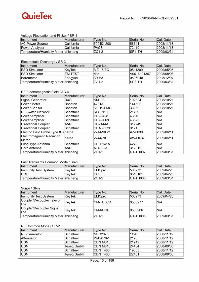
Voltage Fluctuation and Flicker / SR-1 Instrument Manufacturer Type No. Serial No Cal. Date AC Power Source California 5001iX-208 56741 2008/11/18 Power Analyzer California PACS-1 72419 2008/11/18 Temperature/Humidity Meter zhicheng ZC1-2 SR1-TH 2009/03/31 Electrostatic Discharge / SR-3 Instrument Manufacturer Type No. Serial No Cal. Date ESD Simulator KeyTek MZ-15/EC 0511209 2009/05/05 ESD Simulator EM TEST dito V0616101367 2008/08/08 Barometer Fengyun DYM3 0506048 2008/12/07 Temperature/Humidity Meter zhicheng ZC1-2 SR3-TH 2009/03/31 RF Electromagnetic Field / AC-4 Instrument Manufacturer Type No. Serial No Cal. Date Signal Generator R&S SML03 102324 2008/10/21 Power Meter Boonton 4231A 144502 2008/10/21 Power Sensor Boonton 51011-EMC 33859 2008/10/21 RF Switch Network Schaffner RFS N100 21799 N/A Power Amplifier Schaffner CBA9428 43516 N/A Power Amplifier Schaffner CBA9413B 43526 N/A Directional Coupler A&R DC7144A 312249 N/A Directional Coupler Schaffner CHA 9652B 0121 N/A Electric Field Probe Type 8.3 narda 2244/90.21 AZ-0030 2009/06/11 Electromagnetic Radiation Meter narda 2244/70 AW-0074 2009/06/11
Bilog Type Antenna Schaffner CBL6141A 4278 N/A Horn Antenna A&R AT4002A 312312 N/A Temperature/Humidity Meter zhicheng ZC1-2 QT-TH007 2009/03/31 Fast Transients Common Mode / SR-2 Instrument Manufacturer Type No. Serial No Cal. Date Immunity Test System KeyTek EMCpro 508273 2009/04/23 CCL KeyTek CCL 0510181 2009/04/23 Temperature/Humidity Meter zhicheng ZC1-2 QT-TH005 2009/03/31 Surge / SR-2 Instrument Manufacturer Type No. Serial No Cal. Date Immunity Test System KeyTek EMCpro 508273 2009/04/23 Coupler/Decoupler Telecom line KeyTek CM-TELCD 0506277 N/A
Coupler/Decoupler Signal line KeyTek CM-I/OCD 0508206 N/A
Temperature/Humidity Meter zhicheng ZC1-2 QT-TH005 2009/03/31 RF Common Mode / SR-2 Instrument Manufacturer Type No. Serial No Cal. Date RF-Generator Schaffner NSG2070 1120 2008/11/12 Attenuator Schaffner INA2070-1 2120 2008/11/12 CDN Schaffner CDN M016 21249 2008/11/12 CDN Teseq GmbH CDN M016 24484 2008/09/03 CDN Schaffner CDN T400 19083 2008/11/12 CDN Teseq GmbH CDN T400 22461 2008/09/03

Report No: 096S040-RF-CE-P02V01
Page: 16 of 159
EM Clamp Schaffner KEMZ 801 21041 2008/11/12 50ohm Termination SHX TF2 07081404 2008/09/28 50ohm Termination SHX TF2 07081405 2008/09/28 50ohm Termination SHX TF2 07081406 2008/09/28 Temperature/Humidity Meter zhicheng ZC1-2 QT-TH005 2009/03/31 *Transients and Surges / No.4 Shielded Rom Instrument Manufacturer Type No. Serial No Cal. Date Transient Generator Schaffner MT5510-750-0034 67 2008/11/01 Burst Generator Schaffner FT5530-70-0033r01 74 2008/11/01 Load Dump Generator Schaffner LD5505-750-0045r01 35 2008/11/01 Impedance Generator Schaffner RM5505-750-057r01 14 2008/11/01 Power Amplifier Generator Schaffner PA5840-75 / 581-0005 2008/11/01 Function/Wave Generator
Schaffner FG5620-750-0051-00 35 2008/11/01
Note: “*” means this test is performed in HsinChu Testing Laboratory.
Report No: 096S040-RF-CE-P02V01
Page: 17 of 159
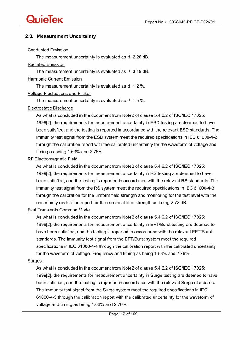
2.3. Measurement Uncertainty Conducted Emission
The measurement uncertainty is evaluated as ± 2.26 dB.
Radiated Emission The measurement uncertainty is evaluated as ± 3.19 dB.
Harmonic Current Emission The measurement uncertainty is evaluated as ± 1.2 %.
Voltage Fluctuations and Flicker The measurement uncertainty is evaluated as ± 1.5 %.
Electrostatic Discharge As what is concluded in the document from Note2 of clause 5.4.6.2 of ISO/IEC 17025: 1999[2], the requirements for measurement uncertainty in ESD testing are deemed to have been satisfied, and the testing is reported in accordance with the relevant ESD standards. The immunity test signal from the ESD system meet the required specifications in IEC 61000-4-2 through the calibration report with the calibrated uncertainty for the waveform of voltage and timing as being 1.63% and 2.76%.
RF Electromagnetic Field As what is concluded in the document from Note2 of clause 5.4.6.2 of ISO/IEC 17025: 1999[2], the requirements for measurement uncertainty in RS testing are deemed to have been satisfied, and the testing is reported in accordance with the relevant RS standards. The immunity test signal from the RS system meet the required specifications in IEC 61000-4-3 through the calibration for the uniform field strength and monitoring for the test level with the uncertainty evaluation report for the electrical filed strength as being 2.72 dB.
Fast Transients Common Mode As what is concluded in the document from Note2 of clause 5.4.6.2 of ISO/IEC 17025: 1999[2], the requirements for measurement uncertainty in EFT/Burst testing are deemed to have been satisfied, and the testing is reported in accordance with the relevant EFT/Burst standards. The immunity test signal from the EFT/Burst system meet the required specifications in IEC 61000-4-4 through the calibration report with the calibrated uncertainty for the waveform of voltage. Frequency and timing as being 1.63% and 2.76%.
Surges As what is concluded in the document from Note2 of clause 5.4.6.2 of ISO/IEC 17025: 1999[2], the requirements for measurement uncertainty in Surge testing are deemed to have been satisfied, and the testing is reported in accordance with the relevant Surge standards. The immunity test signal from the Surge system meet the required specifications in IEC 61000-4-5 through the calibration report with the calibrated uncertainty for the waveform of voltage and timing as being 1.63% and 2.76%.

Report No: 096S040-RF-CE-P02V01
Page: 18 of 159
RF Common Mode As what is concluded in the document from Note2 of clause 5.4.6.2 of ISO/IEC 17025: 1999[2], the requirements for measurement uncertainty in CS testing are deemed to have been satisfied, and the testing is reported in accordance with the relevant CS standards. The immunity test signal from the CS system meet the required specifications in IEC 61000-4-6 through the calibration for unmodulated signal and monitoring for the test level with the uncertainty evaluation report for the injected modulated signal level through CDN and EM Clamp/Direct Injection as being 3.72 dB and 2.78 dB.
Voltage Dips and Interruption As what is concluded in the document from Note2 of clause 5.4.6.2 of ISO/IEC 17025: 1999[2], the requirements for measurement uncertainty in DIP testing are deemed to have been satisfied, and the testing is reported in accordance with the relevant DIP standards. The immunity test signal from the DIP system meet the required specifications in IEC 61000-4-11 through the calibration report with the calibrated uncertainty for the waveform of voltage and timing as being 1.63% and 2.76%.
Transients and Surges As what is concluded in the document from Note2 of clause 5.4.6.2 of ISO/IEC 17025: 1999[2], the requirements for measurement uncertainty in Transients and Surges testing are deemed to have been satisfied, and the testing is reported in accordance with the relevant DIP standards. The immunity test signal from the Transients and Surges system meet the required specifications in ISO 7637-2 through the calibration report with the calibrated uncertainty for the waveform of voltage and timing as being 1.60% and 2.60%.
Report No: 096S040-RF-CE-P02V01
Page: 19 of 159
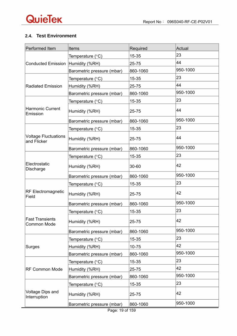
2.4. Test Environment Performed Item Items Required Actual
Temperature (°C) 15-35 23
Conducted Emission Humidity (%RH) 25-75 44
Barometric pressure (mbar) 860-1060 950-1000
Temperature (°C) 15-35 23
Radiated Emission Humidity (%RH) 25-75 44
Barometric pressure (mbar) 860-1060 950-1000
Temperature (°C) 15-35 23
Harmonic Current Emission Humidity (%RH) 25-75 44
Barometric pressure (mbar) 860-1060 950-1000
Temperature (°C) 15-35 23
Voltage Fluctuations and Flicker Humidity (%RH) 25-75 44
Barometric pressure (mbar) 860-1060 950-1000
Temperature (°C) 15-35 23
Electrostatic Discharge Humidity (%RH) 30-60 42
Barometric pressure (mbar) 860-1060 950-1000
Temperature (°C) 15-35 23
RF Electromagnetic Field Humidity (%RH) 25-75 42
Barometric pressure (mbar) 860-1060 950-1000
Temperature (°C) 15-35 23
Fast Transients Common Mode Humidity (%RH) 25-75 42
Barometric pressure (mbar) 860-1060 950-1000
Temperature (°C) 15-35 23
Surges Humidity (%RH) 10-75 42
Barometric pressure (mbar) 860-1060 950-1000
Temperature (°C) 15-35 23
RF Common Mode Humidity (%RH) 25-75 42
Barometric pressure (mbar) 860-1060 950-1000
Temperature (°C) 15-35 23
Voltage Dips and Interruption Humidity (%RH) 25-75 42
Barometric pressure (mbar) 860-1060 950-1000
Report No: 096S040-RF-CE-P02V01
Page: 20 of 159
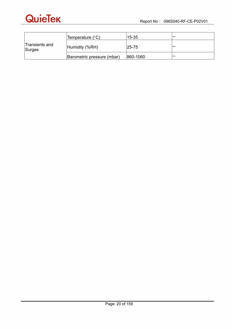
Temperature (°C) 15-35 --
Transients and Surges Humidity (%RH) 25-75 --
Barometric pressure (mbar) 860-1060 --
Report No: 096S040-RF-CE-P02V01
Page: 21 of 159
2.5. Performance criteria The performance criteria criteria are used to take a decision on whether a radio equipment passes or fails immunity tests. For the purpose of the present document four categories of performance criteria apply:
performance criteria for continuous phenomena applied to transmitters; performance criteria for transient phenomena applied to transmitters; performance criteria for continuous phenomena applied to receivers; performance criteria for transient phenomena applied to receivers.
Normally, the performance criteria depend on the type of radio equipment. Thus, the present document only contains general performance criteria commonly used for the assessment of radio equipment. More specific and product-related performance criteria for a dedicated type of radio equipment may be found in the part of EN 301 489 series [22] dealing with the particular type of radio equipment. (1) Performance criteria for continuous phenomena applied to transmitters and receivers If no further details are given in the relevant part of EN 301 489 series [22] dealing with the particular type of radio equipment, the following general performance criteria for continuous phenomena shall apply. During and after the test, the apparatus shall continue to operate as intended. No degradation of performance or loss of function is allowed a permissible performance level specified by the manufacturer when the apparatus is used as intended. In some cases this permissible performance level may be replaced by a permissible loss of performance. During the test the EUT shall not unintentionally transmit or change its actual operating state and stored data. If the minimum performance level or the permissible performance loss is not specified by the manufacturer, then either of these may be deduced from the product description and documentation and what the user may reasonably expect from the apparatus if used as intended. (2) Performance criteria for transient phenomena applied to transmitters and receivers If no further details are given in the relevant part of EN 301 489 series [22] dealing with the particular type of radio equipment, the following general performance criteria for transient phenomena shall apply. After the test, the apparatus shall continue to operate as intended. No degradation of performance or

Report No: 096S040-RF-CE-P02V01
Page: 22 of 159
loss of function is allowed below a permissible performance level specified by the manufacturer, when the apparatus is used as intended. In some cases this permissible performance level may be replaced by a permissible loss of performance. During the EMC exposure to an electromagnetic phenomenon, a degradation of performance is, however, allowed. No change of the actual mode of operation (e.g. unintended transmission) or stored data is allowed. If the minimum performance level or the permissible performance loss is not specified by the manufacturer, then either of these may be deduced from the product description and documentation and what the user may reasonably expect from the apparatus if used as intended. (3) Performance criteria for equipment which does not provide a continuous communication
link For radio equipment which does not provide a continuous communication link, the performance criteria described in clauses (1) and (2) are not appropriate, then the manufacturer shall declare, for inclusion in the test report, his own specification for an acceptable level of performance or degradation of performance during and/or after the immunity tests. The performance specification shall be included in the product description and documentation. The related specifications set out in clause 5.3 of EN 301 489-1 V1.6.1 (2005-09) have also to be taken into account. The performance criteria specified by the manufacturer shall give the same degree of immunity protection as called for in clauses (1) and (2). (4) Performance criteria for ancillary equipment tested on a stand alone basis If ancillary equipment is intended to be tested on a stand alone basis, the performance criteria described in clauses (1) and (2) are not appropriate, then the manufacturer shall declare, for inclusion in the test report, his own specification for an acceptable level of performance or degradation of performance during and/or after the immunity tests. The performance specification shall be included in the product description and documentation. The related specifications set out in clause 5.3 of EN 301 489-1 V1.6.1 (2005-09) have also to be taken into account. The performance criteria specified by the manufacturer shall give the same degree of immunity protection as called for in clauses (1) and (2).

Report No: 096S040-RF-CE-P02V01
Page: 23 of 159
Performance table Performance criteria
Criteria During Test After test A Shall operate as intended
May show degradation of performance (see note 1)
Shall be no loss of function Shall be no unintentional
transmissions
Shall operate as intended Shall be no degradation of performance
(see note 2) Shall be no loss of function Shall be no loss of stored data or user
programmable functions
B May show loss of function (one or more)
May show degradation of performance (see note 1)
No unintentional transmission
Functions shall be self-recoverable Shall operate as intended after recovering Shall be no degradation of performance
(see note 2) Shall be no loss of stored data or user
programmable functions
C May be loss of function (one or more)
Functions shall be recoverable by the operator
Shall operate as intended after recovering Shall be no degradation of performance
(see note 2)
Note 1: Degradation of performance during the test is understood as a degradation to a level not below a minimum performance level specified by the manufacturer for the use of the apparatus as intended. In some cases the specified minimum performance level may be replaced by a permissible degradation of performance.
If the minimum performance level or the permissible performance degradation is not specified by the manufacturer then either of these may be derived from the product description and documentation (including leaflets and advertising) and what the user may reasonably expect from the apparatus if used as intended.
Note 2: No degradation of performance after the test is understood as no degradation below a minimum performance level specified by the manufacturer for the use of the apparatus as intended. In some cases the specified minimum performance level may be replaced by a permissible degradation of performance. After the test no change of actual operating data or user retrievable data is allowed. If the minimum performance level or the permissible performance degradation is not specified by the manufacturer then either of these may be derived from the product description and documentation (including leaflets and advertising) and what the user may reasonably expect from the apparatus if used as intended.

Report No: 096S040-RF-CE-P02V01
Page: 24 of 159
3. Conducted Emission (AC input/output Ports)
3.1. Test Specification
According to EMC Standard: EN 55022 Class B
3.2. Test Setup
3.3. Limit
Limits for conducted emssions of equipment intended to be used in
telecommunication centres only
Frequency (MHz)
QP (dBuV)
AV (dBuV)
0.15 - 0.50 79 66
0.50 - 30 73 60
Note: The lower limit shall apply at the transition frequencies.
Report No: 096S040-RF-CE-P02V01
Page: 25 of 159
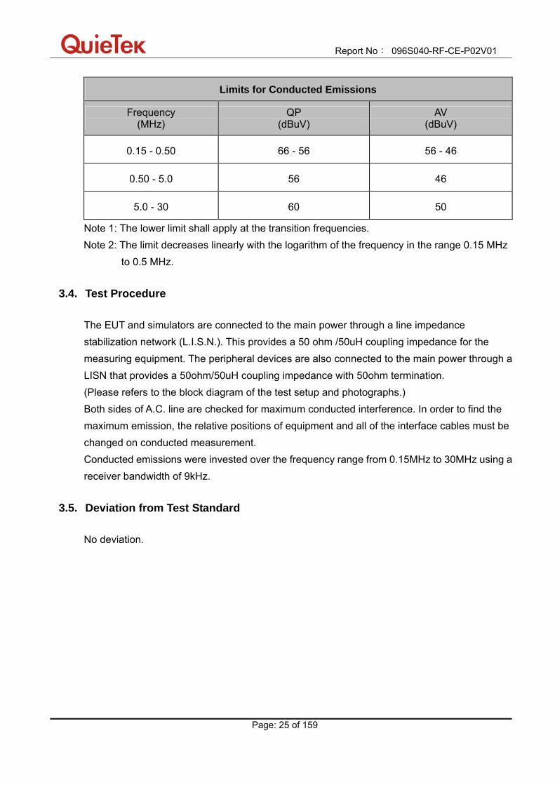
Limits for Conducted Emissions
Frequency (MHz)
QP (dBuV)
AV (dBuV)
0.15 - 0.50 66 - 56 56 - 46
0.50 - 5.0 56 46
5.0 - 30 60 50
Note 1: The lower limit shall apply at the transition frequencies. Note 2: The limit decreases linearly with the logarithm of the frequency in the range 0.15 MHz
to 0.5 MHz.
3.4. Test Procedure The EUT and simulators are connected to the main power through a line impedance stabilization network (L.I.S.N.). This provides a 50 ohm /50uH coupling impedance for the measuring equipment. The peripheral devices are also connected to the main power through a LISN that provides a 50ohm/50uH coupling impedance with 50ohm termination. (Please refers to the block diagram of the test setup and photographs.) Both sides of A.C. line are checked for maximum conducted interference. In order to find the maximum emission, the relative positions of equipment and all of the interface cables must be changed on conducted measurement. Conducted emissions were invested over the frequency range from 0.15MHz to 30MHz using a receiver bandwidth of 9kHz.
3.5. Deviation from Test Standard No deviation.
Report No: 096S040-RF-CE-P02V01
Page: 26 of 159
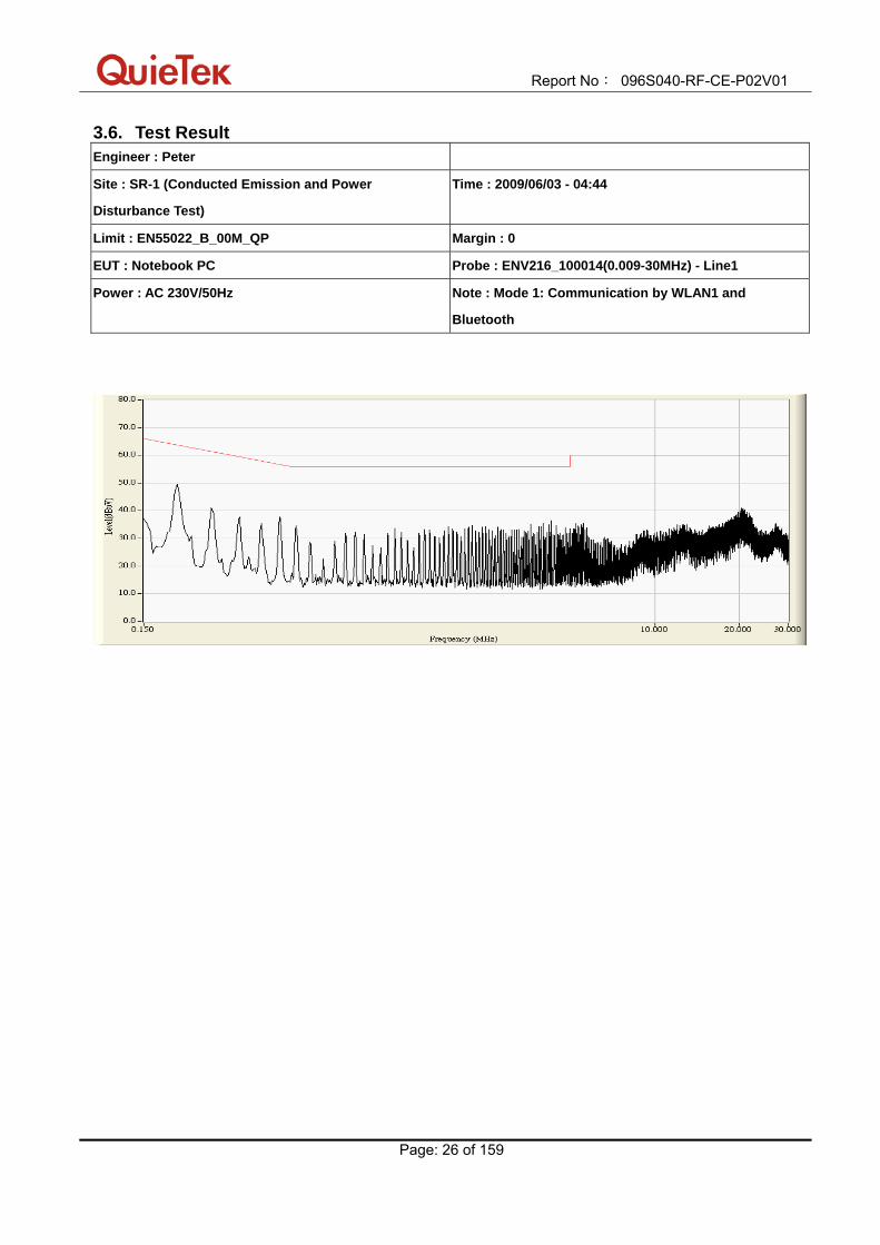
3.6. Test Result Engineer : Peter
Site : SR-1 (Conducted Emission and Power
Disturbance Test)
Time : 2009/06/03 - 04:44
Limit : EN55022_B_00M_QP Margin : 0
EUT : Notebook PC Probe : ENV216_100014(0.009-30MHz) - Line1
Power : AC 230V/50Hz Note : Mode 1: Communication by WLAN1 and
Bluetooth
Report No: 096S040-RF-CE-P02V01
Page: 27 of 159
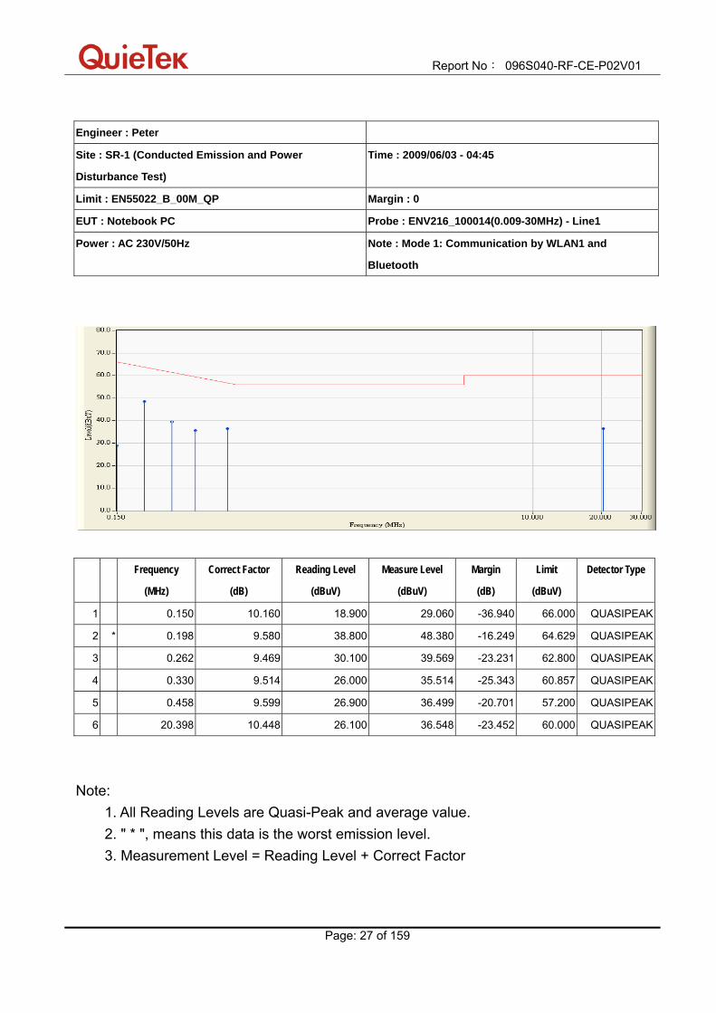
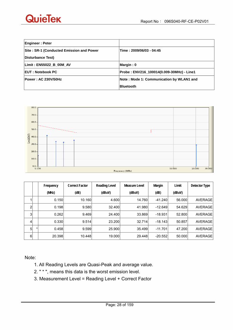
Engineer : Peter
Site : SR-1 (Conducted Emission and Power
Disturbance Test)
Time : 2009/06/03 - 04:45
Limit : EN55022_B_00M_QP Margin : 0
EUT : Notebook PC Probe : ENV216_100014(0.009-30MHz) - Line1
Power : AC 230V/50Hz Note : Mode 1: Communication by WLAN1 and
Bluetooth
Frequency
(MHz)
Correct Factor
(dB)
Reading Level
(dBuV)
Measure Level
(dBuV)
Margin
(dB)
Limit
(dBuV)
Detector Type
1 0.150 10.160 18.900 29.060 -36.940 66.000 QUASIPEAK
2 * 0.198 9.580 38.800 48.380 -16.249 64.629 QUASIPEAK
3 0.262 9.469 30.100 39.569 -23.231 62.800 QUASIPEAK
4 0.330 9.514 26.000 35.514 -25.343 60.857 QUASIPEAK
5 0.458 9.599 26.900 36.499 -20.701 57.200 QUASIPEAK
6 20.398 10.448 26.100 36.548 -23.452 60.000 QUASIPEAK
Note: 1. All Reading Levels are Quasi-Peak and average value. 2. " * ", means this data is the worst emission level. 3. Measurement Level = Reading Level + Correct Factor
Report No: 096S040-RF-CE-P02V01
Page: 28 of 159
Engineer : Peter
Site : SR-1 (Conducted Emission and Power
Disturbance Test)
Time : 2009/06/03 - 04:45
Limit : EN55022_B_00M_AV Margin : 0
EUT : Notebook PC Probe : ENV216_100014(0.009-30MHz) - Line1
Power : AC 230V/50Hz Note : Mode 1: Communication by WLAN1 and
Bluetooth
Frequency
(MHz)
Correct Factor
(dB)
Reading Level
(dBuV)
Measure Level
(dBuV)
Margin
(dB)
Limit
(dBuV)
Detector Type
1 0.150 10.160 4.600 14.760 -41.240 56.000 AVERAGE
2 0.198 9.580 32.400 41.980 -12.649 54.629 AVERAGE
3 0.262 9.469 24.400 33.869 -18.931 52.800 AVERAGE
4 0.330 9.514 23.200 32.714 -18.143 50.857 AVERAGE
5 * 0.458 9.599 25.900 35.499 -11.701 47.200 AVERAGE
6 20.398 10.448 19.000 29.448 -20.552 50.000 AVERAGE
Note: 1. All Reading Levels are Quasi-Peak and average value. 2. " * ", means this data is the worst emission level. 3. Measurement Level = Reading Level + Correct Factor

Report No: 096S040-RF-CE-P02V01
Page: 29 of 159
Engineer : Peter
Site : SR-1 (Conducted Emission and Power
Disturbance Test)
Time : 2009/06/03 - 04:47
Limit : EN55022_B_00M_QP Margin : 0
EUT : Notebook PC Probe : ENV216_100014(0.009-30MHz) - Line2
Power : AC 230V/50Hz Note : Mode 1: Communication by WLAN1 and
Bluetooth

Report No: 096S040-RF-CE-P02V01
Page: 30 of 159
Engineer : Peter
Site : SR-1 (Conducted Emission and Power
Disturbance Test)
Time : 2009/06/03 - 04:49
Limit : EN55022_B_00M_QP Margin : 0
EUT : Notebook PC Probe : ENV216_100014(0.009-30MHz) - Line2
Power : AC 230V/50Hz Note : Mode 1: Communication by WLAN1 and
Bluetooth
Frequency
(MHz)
Correct Factor
(dB)
Reading Level
(dBuV)
Measure Level
(dBuV)
Margin
(dB)
Limit
(dBuV)
Detector Type
1 0.150 10.006 18.400 28.406 -37.594 66.000 QUASIPEAK
2 * 0.198 9.664 36.300 45.964 -18.665 64.629 QUASIPEAK
3 0.262 9.584 28.000 37.584 -25.216 62.800 QUASIPEAK
4 0.326 9.590 24.400 33.990 -26.981 60.971 QUASIPEAK
5 3.870 9.720 21.500 31.220 -24.780 56.000 QUASIPEAK
6 20.334 10.420 25.000 35.420 -24.580 60.000 QUASIPEAK
Note: 1. All Reading Levels are Quasi-Peak and average value. 2. " * ", means this data is the worst emission level. 3. Measurement Level = Reading Level + Correct Factor
Report No: 096S040-RF-CE-P02V01
Page: 31 of 159
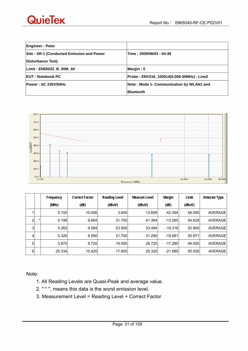
Engineer : Peter
Site : SR-1 (Conducted Emission and Power
Disturbance Test)
Time : 2009/06/03 - 04:49
Limit : EN55022_B_00M_AV Margin : 0
EUT : Notebook PC Probe : ENV216_100014(0.009-30MHz) - Line2
Power : AC 230V/50Hz Note : Mode 1: Communication by WLAN1 and
Bluetooth
Frequency
(MHz)
Correct Factor
(dB)
Reading Level
(dBuV)
Measure Level
(dBuV)
Margin
(dB)
Limit
(dBuV)
Detector Type
1 0.150 10.006 3.600 13.606 -42.394 56.000 AVERAGE
2 * 0.198 9.664 31.700 41.364 -13.265 54.629 AVERAGE
3 0.262 9.584 23.900 33.484 -19.316 52.800 AVERAGE
4 0.326 9.590 21.700 31.290 -19.681 50.971 AVERAGE
5 3.870 9.720 19.000 28.720 -17.280 46.000 AVERAGE
6 20.334 10.420 17.900 28.320 -21.680 50.000 AVERAGE
Note: 1. All Reading Levels are Quasi-Peak and average value. 2. " * ", means this data is the worst emission level. 3. Measurement Level = Reading Level + Correct Factor

Report No: 096S040-RF-CE-P02V01
Page: 32 of 159
Engineer : Peter
Site : SR-1 (Conducted Emission and Power
Disturbance Test)
Time : 2009/06/03 - 05:51
Limit : EN55022_B_00M_QP Margin : 0
EUT : Notebook PC Probe : ENV216_100014(0.009-30MHz) - Line1
Power : AC 230V/50Hz Note : Mode 3: Communication by WLAN2 and
Bluetooth

Report No: 096S040-RF-CE-P02V01
Page: 33 of 159
Engineer : Peter
Site : SR-1 (Conducted Emission and Power
Disturbance Test)
Time : 2009/06/03 - 05:53
Limit : EN55022_B_00M_QP Margin : 0
EUT : Notebook PC Probe : ENV216_100014(0.009-30MHz) - Line1
Power : AC 230V/50Hz Note : Mode 3: Communication by WLAN2 and
Bluetooth
Frequency
(MHz)
Correct Factor
(dB)
Reading Level
(dBuV)
Measure Level
(dBuV)
Margin
(dB)
Limit
(dBuV)
Detector Type
1 0.150 10.160 38.400 48.560 -17.440 66.000 QUASIPEAK
2 * 0.206 9.526 41.500 51.026 -13.374 64.400 QUASIPEAK
3 0.262 9.469 33.700 43.169 -19.631 62.800 QUASIPEAK
4 0.294 9.490 24.800 34.290 -27.596 61.886 QUASIPEAK
5 12.678 10.170 27.400 37.570 -22.430 60.000 QUASIPEAK
6 23.566 10.660 31.300 41.960 -18.040 60.000 QUASIPEAK
Note: 1. All Reading Levels are Quasi-Peak and average value. 2. " * ", means this data is the worst emission level. 3. Measurement Level = Reading Level + Correct Factor

Report No: 096S040-RF-CE-P02V01
Page: 34 of 159
Engineer : Peter
Site : SR-1 (Conducted Emission and Power
Disturbance Test)
Time : 2009/06/03 - 05:53
Limit : EN55022_B_00M_AV Margin : 0
EUT : Notebook PC Probe : ENV216_100014(0.009-30MHz) - Line1
Power : AC 230V/50Hz Note : Mode 3: Communication by WLAN2 and
Bluetooth
Frequency
(MHz)
Correct Factor
(dB)
Reading Level
(dBuV)
Measure Level
(dBuV)
Margin
(dB)
Limit
(dBuV)
Detector Type
1 0.150 10.160 22.200 32.360 -23.640 56.000 AVERAGE
2 0.206 9.526 29.700 39.226 -15.174 54.400 AVERAGE
3 0.262 9.469 20.000 29.469 -23.331 52.800 AVERAGE
4 0.294 9.490 12.900 22.390 -29.496 51.886 AVERAGE
5 12.678 10.170 19.300 29.470 -20.530 50.000 AVERAGE
6 * 23.566 10.660 25.300 35.960 -14.040 50.000 AVERAGE
Note: 1. All Reading Levels are Quasi-Peak and average value. 2. " * ", means this data is the worst emission level. 3. Measurement Level = Reading Level + Correct Factor
Report No: 096S040-RF-CE-P02V01
Page: 35 of 159
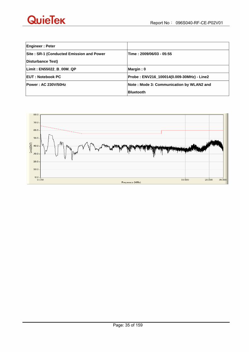
Engineer : Peter
Site : SR-1 (Conducted Emission and Power
Disturbance Test)
Time : 2009/06/03 - 05:55
Limit : EN55022_B_00M_QP Margin : 0
EUT : Notebook PC Probe : ENV216_100014(0.009-30MHz) - Line2
Power : AC 230V/50Hz Note : Mode 3: Communication by WLAN2 and
Bluetooth

Report No: 096S040-RF-CE-P02V01
Page: 36 of 159
Engineer : Peter
Site : SR-1 (Conducted Emission and Power
Disturbance Test)
Time : 2009/06/03 - 05:57
Limit : EN55022_B_00M_QP Margin : 0
EUT : Notebook PC Probe : ENV216_100014(0.009-30MHz) - Line2
Power : AC 230V/50Hz Note : Mode 3: Communication by WLAN2 and
Bluetooth
Frequency
(MHz)
Correct Factor
(dB)
Reading Level
(dBuV)
Measure Level
(dBuV)
Margin
(dB)
Limit
(dBuV)
Detector Type
1 0.150 10.006 37.400 47.406 -18.594 66.000 QUASIPEAK
2 0.194 9.680 41.600 51.280 -13.463 64.743 QUASIPEAK
3 0.266 9.586 32.300 41.886 -20.800 62.686 QUASIPEAK
4 * 0.582 9.682 34.200 43.882 -12.118 56.000 QUASIPEAK
5 0.654 9.730 33.300 43.030 -12.970 56.000 QUASIPEAK
6 21.690 10.470 31.200 41.670 -18.330 60.000 QUASIPEAK
Note: 1. All Reading Levels are Quasi-Peak and average value. 2. " * ", means this data is the worst emission level. 3. Measurement Level = Reading Level + Correct Factor
Report No: 096S040-RF-CE-P02V01
Page: 37 of 159
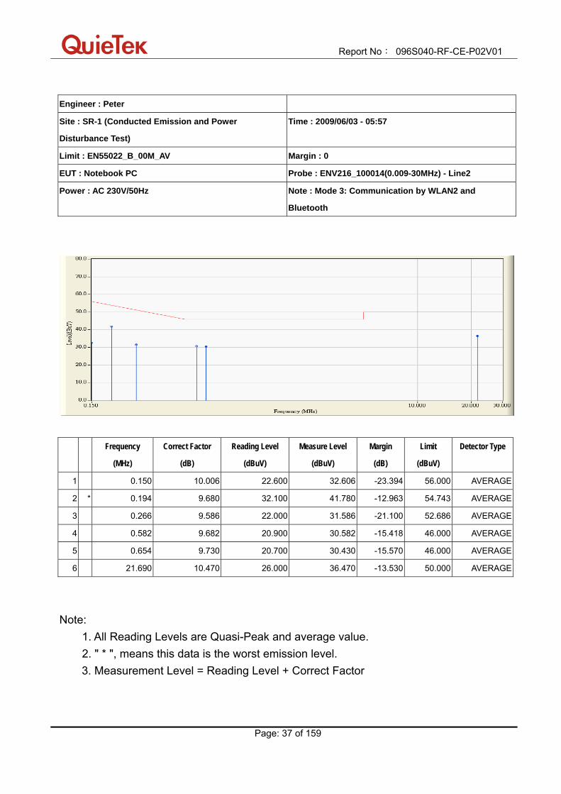
Engineer : Peter
Site : SR-1 (Conducted Emission and Power
Disturbance Test)
Time : 2009/06/03 - 05:57
Limit : EN55022_B_00M_AV Margin : 0
EUT : Notebook PC Probe : ENV216_100014(0.009-30MHz) - Line2
Power : AC 230V/50Hz Note : Mode 3: Communication by WLAN2 and
Bluetooth
Frequency
(MHz)
Correct Factor
(dB)
Reading Level
(dBuV)
Measure Level
(dBuV)
Margin
(dB)
Limit
(dBuV)
Detector Type
1 0.150 10.006 22.600 32.606 -23.394 56.000 AVERAGE
2 * 0.194 9.680 32.100 41.780 -12.963 54.743 AVERAGE
3 0.266 9.586 22.000 31.586 -21.100 52.686 AVERAGE
4 0.582 9.682 20.900 30.582 -15.418 46.000 AVERAGE
5 0.654 9.730 20.700 30.430 -15.570 46.000 AVERAGE
6 21.690 10.470 26.000 36.470 -13.530 50.000 AVERAGE
Note: 1. All Reading Levels are Quasi-Peak and average value. 2. " * ", means this data is the worst emission level.
3. Measurement Level = Reading Level + Correct Factor

Report No: 096S040-RF-CE-P02V01
Page: 38 of 159
3.7. Test Photograph Test Mode: Mode 1: Communication by WLAN1 and Bluetooth Description: Front View of Conducted Emission Test Setup (AC input/output Ports)
Test Mode: Mode 1: Communication by WLAN1 and Bluetooth Description: Back View of Conducted Emission Test Setup (AC input/output Ports)
Report No: 096S040-RF-CE-P02V01
Page: 39 of 159
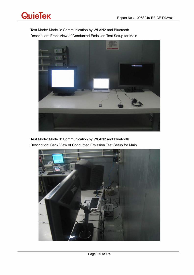
Test Mode: Mode 3: Communication by WLAN2 and Bluetooth Description: Front View of Conducted Emission Test Setup for Main
Test Mode: Mode 3: Communication by WLAN2 and Bluetooth Description: Back View of Conducted Emission Test Setup for Main
Report No: 096S040-RF-CE-P02V01
Page: 40 of 159
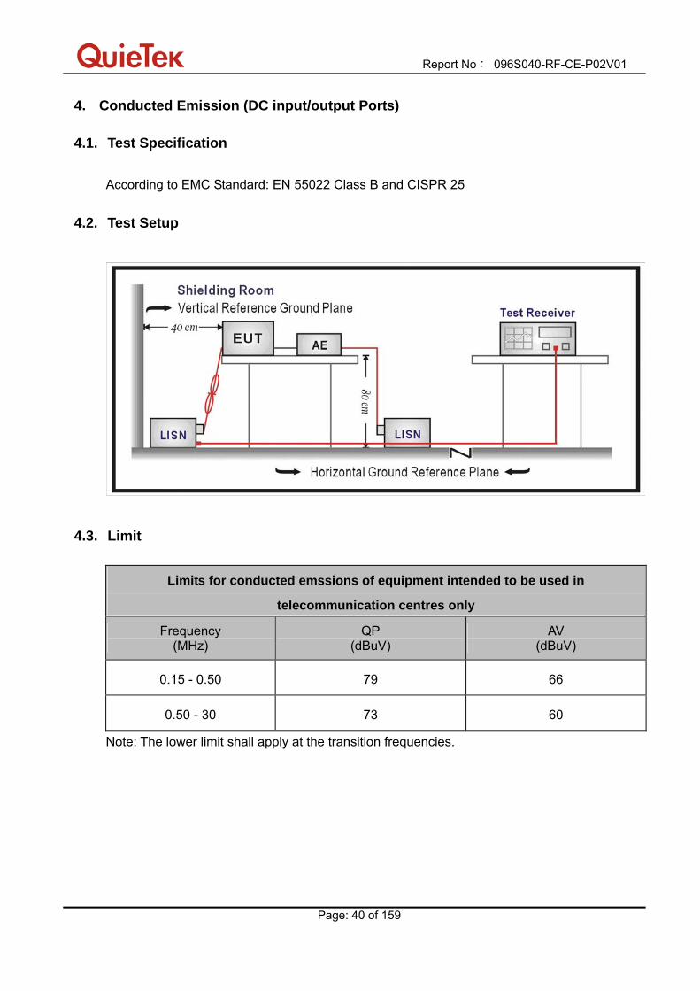
4. Conducted Emission (DC input/output Ports)
4.1. Test Specification
According to EMC Standard: EN 55022 Class B and CISPR 25
4.2. Test Setup
4.3. Limit
Limits for conducted emssions of equipment intended to be used in
telecommunication centres only
Frequency (MHz)
QP (dBuV)
AV (dBuV)
0.15 - 0.50 79 66
0.50 - 30 73 60
Note: The lower limit shall apply at the transition frequencies.
Report No: 096S040-RF-CE-P02V01
Page: 41 of 159
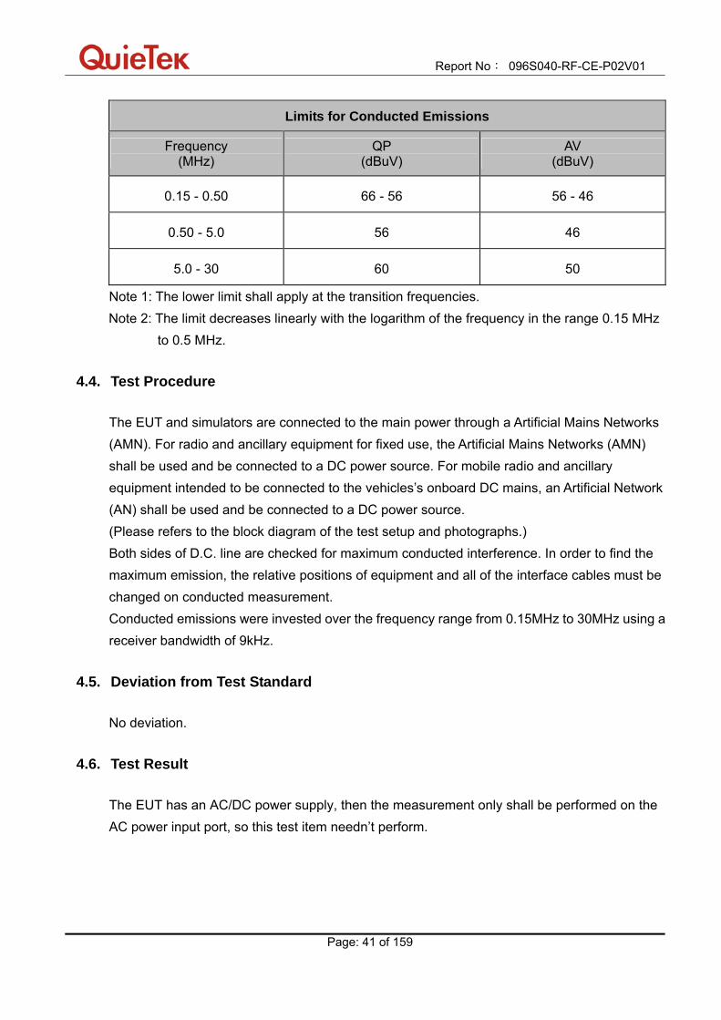
Limits for Conducted Emissions
Frequency (MHz)
QP (dBuV)
AV (dBuV)
0.15 - 0.50 66 - 56 56 - 46
0.50 - 5.0 56 46
5.0 - 30 60 50
Note 1: The lower limit shall apply at the transition frequencies. Note 2: The limit decreases linearly with the logarithm of the frequency in the range 0.15 MHz
to 0.5 MHz.
4.4. Test Procedure The EUT and simulators are connected to the main power through a Artificial Mains Networks (AMN). For radio and ancillary equipment for fixed use, the Artificial Mains Networks (AMN) shall be used and be connected to a DC power source. For mobile radio and ancillary equipment intended to be connected to the vehicles’s onboard DC mains, an Artificial Network (AN) shall be used and be connected to a DC power source. (Please refers to the block diagram of the test setup and photographs.) Both sides of D.C. line are checked for maximum conducted interference. In order to find the maximum emission, the relative positions of equipment and all of the interface cables must be changed on conducted measurement. Conducted emissions were invested over the frequency range from 0.15MHz to 30MHz using a receiver bandwidth of 9kHz.
4.5. Deviation from Test Standard No deviation.
4.6. Test Result The EUT has an AC/DC power supply, then the measurement only shall be performed on the AC power input port, so this test item needn’t perform.
Report No: 096S040-RF-CE-P02V01
Page: 42 of 159
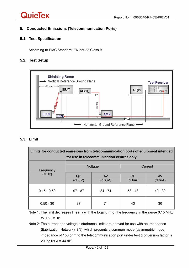
5. Conducted Emissions (Telecommunication Ports)
5.1. Test Specification According to EMC Standard: EN 55022 Class B
5.2. Test Setup
5.3. Limit
Limits for conducted emissions from telecommunication ports of equipment intended for use in telecommunication centres only
Voltage Current Frequency
(MHz) QP (dBuV)
AV (dBuV)
QP (dBuA)
AV (dBuA)
0.15 - 0.50 97 - 87 84 - 74 53 - 43 40 - 30
0.50 - 30 87 74 43 30
Note 1: The limit decreases linearly with the logarithm of the frequency in the range 0.15 MHz to 0.50 MHz.
Note 2: The current and voltage disturbance limits are derived for use with an Impedance Stabilization Network (ISN), which presents a common mode (asymmetric mode) impedance of 150 ohm to the telecommunication port under test (conversion factor is 20 log150/I = 44 dB).

Report No: 096S040-RF-CE-P02V01
Page: 43 of 159
Limits for conducted emissions from telecommunication ports
Voltage Current Frequency
(MHz) QP (dBuV)
AV (dBuV)
QP (dBuA)
AV (dBuA)
0.15 - 0.50 84 - 74 74 - 64 40 - 30 30 - 20
0.50 - 30 74 64 30 20
Note 1: The limit decreases linearly with the logarithm of the frequency in the range 0.15 MHz to 0.50 MHz.
Note 2: The current and voltage disturbance limits are derived for use with an Impedance Stabilization Network (ISN) which presents common mode (asymmetric mode) impedance of 150 ohm to the telecommunication port under test (conversion factor is 20 log150/I = 44 dB).
Note 3: The emission requirement only applies to telecommunication ports. The provisional relaxation of 10 dB will be reviewed no later than 3 years after the date of withdrawal based on the results and interference cases seen in this period. Wherever possible it is recommended to comply with the limits without the provisional relaxation.
5.4. Test Procedure
The mains voltage shall be supplied to the EUT via the LISN when the measurement of telecommunication port is performed. The common mode disturbances at the telecommunication port shall be connected to the ISN, which is 150 ohm impedance. Both alternative cables are tested related to the LCL requested. The measurement range is from 150kHz to 30MHz. The bandwidth of measurement is set to 9kHz.
5.5. Deviation from Test Standard No deviation.

Report No: 096S040-RF-CE-P02V01
Page: 44 of 159
5.6. Test Result Engineer : Peter
Site : SR-1 (Conducted Emission and Power
Disturbance Test)
Time : 2009/06/03 - 05:32
Limit : ISN_Voltage_B_00M_QP Margin : 0
EUT : Notebook PC Probe : FCC-TLISN-T4_20353(0.15-30MHz) - Line1
Power : AC 230V/50Hz Note : Mode 1: Communication by WLAN1 and
Bluetooth – LAN 10Mbps

Report No: 096S040-RF-CE-P02V01
Page: 45 of 159
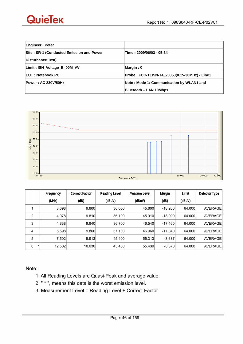
Engineer : Peter
Site : SR-1 (Conducted Emission and Power
Disturbance Test)
Time : 2009/06/03 - 05:34
Limit : ISN_Voltage_B_00M_QP Margin : 0
EUT : Notebook PC Probe : FCC-TLISN-T4_20353(0.15-30MHz) - Line1
Power : AC 230V/50Hz Note : Mode 1: Communication by WLAN1 and
Bluetooth – LAN 10Mbps
Frequency
(MHz)
Correct Factor
(dB)
Reading Level
(dBuV)
Measure Level
(dBuV)
Margin
(dB)
Limit
(dBuV)
Detector Type
1 3.698 9.800 42.500 52.300 -21.700 74.000 QUASIPEAK
2 4.078 9.810 40.900 50.710 -23.290 74.000 QUASIPEAK
3 4.838 9.840 41.300 51.140 -22.860 74.000 QUASIPEAK
4 5.598 9.860 42.000 51.860 -22.140 74.000 QUASIPEAK
5 7.502 9.913 51.300 61.213 -12.787 74.000 QUASIPEAK
6 * 12.502 10.030 52.600 62.630 -11.370 74.000 QUASIPEAK
Note: 1. All Reading Levels are Quasi-Peak and average value. 2. " * ", means this data is the worst emission level. 3. Measurement Level = Reading Level + Correct Factor
Report No: 096S040-RF-CE-P02V01
Page: 46 of 159
Engineer : Peter
Site : SR-1 (Conducted Emission and Power
Disturbance Test)
Time : 2009/06/03 - 05:34
Limit : ISN_Voltage_B_00M_AV Margin : 0
EUT : Notebook PC Probe : FCC-TLISN-T4_20353(0.15-30MHz) - Line1
Power : AC 230V/50Hz Note : Mode 1: Communication by WLAN1 and
Bluetooth – LAN 10Mbps
Frequency
(MHz)
Correct Factor
(dB)
Reading Level
(dBuV)
Measure Level
(dBuV)
Margin
(dB)
Limit
(dBuV)
Detector Type
1 3.698 9.800 36.000 45.800 -18.200 64.000 AVERAGE
2 4.078 9.810 36.100 45.910 -18.090 64.000 AVERAGE
3 4.838 9.840 36.700 46.540 -17.460 64.000 AVERAGE
4 5.598 9.860 37.100 46.960 -17.040 64.000 AVERAGE
5 7.502 9.913 45.400 55.313 -8.687 64.000 AVERAGE
6 * 12.502 10.030 45.400 55.430 -8.570 64.000 AVERAGE
Note: 1. All Reading Levels are Quasi-Peak and average value. 2. " * ", means this data is the worst emission level. 3. Measurement Level = Reading Level + Correct Factor

Report No: 096S040-RF-CE-P02V01
Page: 47 of 159
Engineer : Peter
Site : SR-1 (Conducted Emission and Power
Disturbance Test)
Time : 2009/06/03 - 05:37
Limit : ISN_Voltage_B_00M_QP Margin : 0
EUT : Notebook PC Probe : FCC-TLISN-T4_20353(0.15-30MHz) - Line1
Power : AC 230V/50Hz Note : Mode 1: Communication by WLAN1 and
Bluetooth – LAN 100Mbps
Report No: 096S040-RF-CE-P02V01
Page: 48 of 159
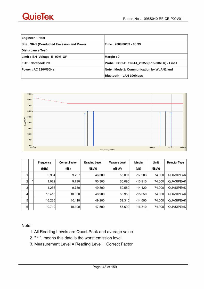
Engineer : Peter
Site : SR-1 (Conducted Emission and Power
Disturbance Test)
Time : 2009/06/03 - 05:39
Limit : ISN_Voltage_B_00M_QP Margin : 0
EUT : Notebook PC Probe : FCC-TLISN-T4_20353(0.15-30MHz) - Line1
Power : AC 230V/50Hz Note : Mode 1: Communication by WLAN1 and
Bluetooth – LAN 100Mbps
Frequency
(MHz)
Correct Factor
(dB)
Reading Level
(dBuV)
Measure Level
(dBuV)
Margin
(dB)
Limit
(dBuV)
Detector Type
1 0.934 9.797 46.300 56.097 -17.903 74.000 QUASIPEAK
2 * 1.022 9.790 50.300 60.090 -13.910 74.000 QUASIPEAK
3 1.266 9.780 49.800 59.580 -14.420 74.000 QUASIPEAK
4 13.418 10.050 48.900 58.950 -15.050 74.000 QUASIPEAK
5 16.226 10.110 49.200 59.310 -14.690 74.000 QUASIPEAK
6 19.710 10.190 47.500 57.690 -16.310 74.000 QUASIPEAK
Note: 1. All Reading Levels are Quasi-Peak and average value. 2. " * ", means this data is the worst emission level. 3. Measurement Level = Reading Level + Correct Factor
Report No: 096S040-RF-CE-P02V01
Page: 49 of 159
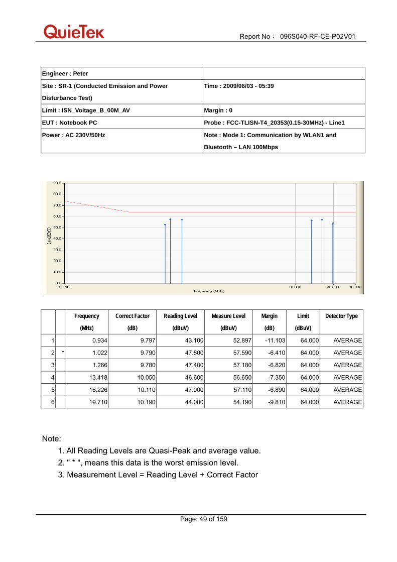
Engineer : Peter
Site : SR-1 (Conducted Emission and Power
Disturbance Test)
Time : 2009/06/03 - 05:39
Limit : ISN_Voltage_B_00M_AV Margin : 0
EUT : Notebook PC Probe : FCC-TLISN-T4_20353(0.15-30MHz) - Line1
Power : AC 230V/50Hz Note : Mode 1: Communication by WLAN1 and
Bluetooth – LAN 100Mbps
Frequency
(MHz)
Correct Factor
(dB)
Reading Level
(dBuV)
Measure Level
(dBuV)
Margin
(dB)
Limit
(dBuV)
Detector Type
1 0.934 9.797 43.100 52.897 -11.103 64.000 AVERAGE
2 * 1.022 9.790 47.800 57.590 -6.410 64.000 AVERAGE
3 1.266 9.780 47.400 57.180 -6.820 64.000 AVERAGE
4 13.418 10.050 46.600 56.650 -7.350 64.000 AVERAGE
5 16.226 10.110 47.000 57.110 -6.890 64.000 AVERAGE
6 19.710 10.190 44.000 54.190 -9.810 64.000 AVERAGE
Note: 1. All Reading Levels are Quasi-Peak and average value. 2. " * ", means this data is the worst emission level. 3. Measurement Level = Reading Level + Correct Factor
Report No: 096S040-RF-CE-P02V01
Page: 50 of 159
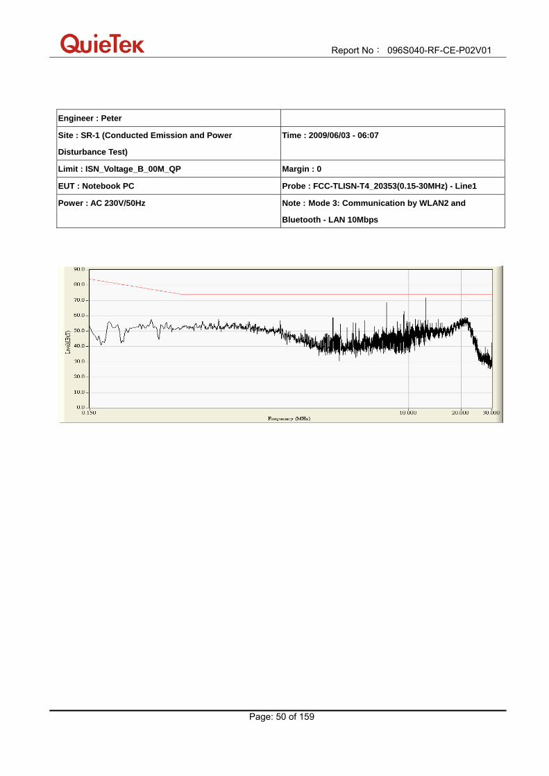
Engineer : Peter
Site : SR-1 (Conducted Emission and Power
Disturbance Test)
Time : 2009/06/03 - 06:07
Limit : ISN_Voltage_B_00M_QP Margin : 0
EUT : Notebook PC Probe : FCC-TLISN-T4_20353(0.15-30MHz) - Line1
Power : AC 230V/50Hz Note : Mode 3: Communication by WLAN2 and
Bluetooth - LAN 10Mbps

Report No: 096S040-RF-CE-P02V01
Page: 51 of 159
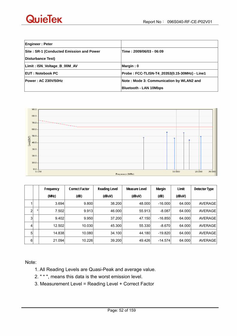
Engineer : Peter
Site : SR-1 (Conducted Emission and Power
Disturbance Test)
Time : 2009/06/03 - 06:09
Limit : ISN_Voltage_B_00M_QP Margin : 0
EUT : Notebook PC Probe : FCC-TLISN-T4_20353(0.15-30MHz) - Line1
Power : AC 230V/50Hz Note : Mode 3: Communication by WLAN2 and
Bluetooth - LAN 10Mbps
Frequency
(MHz)
Correct Factor
(dB)
Reading Level
(dBuV)
Measure Level
(dBuV)
Margin
(dB)
Limit
(dBuV)
Detector Type
1 3.694 9.800 41.900 51.700 -22.300 74.000 QUASIPEAK
2 7.502 9.913 51.600 61.513 -12.487 74.000 QUASIPEAK
3 9.402 9.950 45.100 55.050 -18.950 74.000 QUASIPEAK
4 * 12.502 10.030 53.000 63.030 -10.970 74.000 QUASIPEAK
5 14.838 10.080 40.800 50.880 -23.120 74.000 QUASIPEAK
6 21.094 10.226 44.800 55.026 -18.974 74.000 QUASIPEAK
Note: 1. All Reading Levels are Quasi-Peak and average value. 2. " * ", means this data is the worst emission level. 3. Measurement Level = Reading Level + Correct Factor
Report No: 096S040-RF-CE-P02V01
Page: 52 of 159
Engineer : Peter
Site : SR-1 (Conducted Emission and Power
Disturbance Test)
Time : 2009/06/03 - 06:09
Limit : ISN_Voltage_B_00M_AV Margin : 0
EUT : Notebook PC Probe : FCC-TLISN-T4_20353(0.15-30MHz) - Line1
Power : AC 230V/50Hz Note : Mode 3: Communication by WLAN2 and
Bluetooth - LAN 10Mbps
Frequency
(MHz)
Correct Factor
(dB)
Reading Level
(dBuV)
Measure Level
(dBuV)
Margin
(dB)
Limit
(dBuV)
Detector Type
1 3.694 9.800 38.200 48.000 -16.000 64.000 AVERAGE
2 * 7.502 9.913 46.000 55.913 -8.087 64.000 AVERAGE
3 9.402 9.950 37.200 47.150 -16.850 64.000 AVERAGE
4 12.502 10.030 45.300 55.330 -8.670 64.000 AVERAGE
5 14.838 10.080 34.100 44.180 -19.820 64.000 AVERAGE
6 21.094 10.226 39.200 49.426 -14.574 64.000 AVERAGE
Note: 1. All Reading Levels are Quasi-Peak and average value. 2. " * ", means this data is the worst emission level. 3. Measurement Level = Reading Level + Correct Factor

Report No: 096S040-RF-CE-P02V01
Page: 53 of 159
Engineer : Peter
Site : SR-1 (Conducted Emission and Power
Disturbance Test)
Time : 2009/06/03 - 06:12
Limit : ISN_Voltage_B_00M_QP Margin : 0
EUT : Notebook PC Probe : FCC-TLISN-T4_20353(0.15-30MHz) - Line1
Power : AC 230V/50Hz Note : Mode 3: Communication by WLAN2 and
Bluetooth - LAN 100Mbps
Report No: 096S040-RF-CE-P02V01
Page: 54 of 159
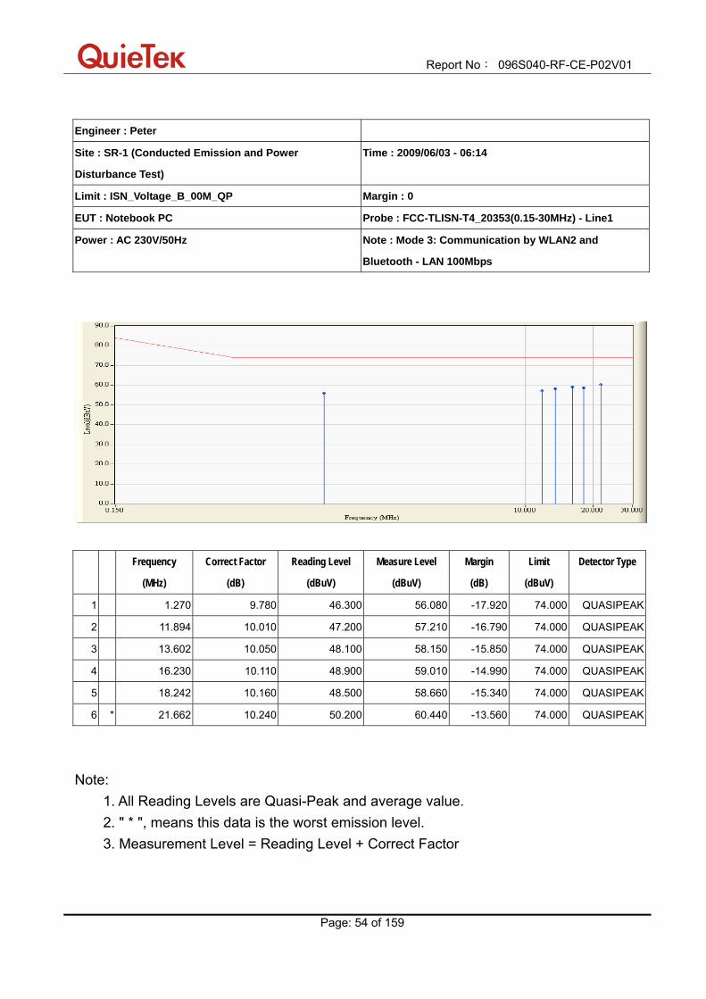
Engineer : Peter
Site : SR-1 (Conducted Emission and Power
Disturbance Test)
Time : 2009/06/03 - 06:14
Limit : ISN_Voltage_B_00M_QP Margin : 0
EUT : Notebook PC Probe : FCC-TLISN-T4_20353(0.15-30MHz) - Line1
Power : AC 230V/50Hz Note : Mode 3: Communication by WLAN2 and
Bluetooth - LAN 100Mbps
Frequency
(MHz)
Correct Factor
(dB)
Reading Level
(dBuV)
Measure Level
(dBuV)
Margin
(dB)
Limit
(dBuV)
Detector Type
1 1.270 9.780 46.300 56.080 -17.920 74.000 QUASIPEAK
2 11.894 10.010 47.200 57.210 -16.790 74.000 QUASIPEAK
3 13.602 10.050 48.100 58.150 -15.850 74.000 QUASIPEAK
4 16.230 10.110 48.900 59.010 -14.990 74.000 QUASIPEAK
5 18.242 10.160 48.500 58.660 -15.340 74.000 QUASIPEAK
6 * 21.662 10.240 50.200 60.440 -13.560 74.000 QUASIPEAK
Note: 1. All Reading Levels are Quasi-Peak and average value. 2. " * ", means this data is the worst emission level. 3. Measurement Level = Reading Level + Correct Factor

Report No: 096S040-RF-CE-P02V01
Page: 55 of 159
Engineer : Peter
Site : SR-1 (Conducted Emission and Power
Disturbance Test)
Time : 2009/06/03 - 06:14
Limit : ISN_Voltage_B_00M_AV Margin : 0
EUT : Notebook PC Probe : FCC-TLISN-T4_20353(0.15-30MHz) - Line1
Power : AC 230V/50Hz Note : Mode 3: Communication by WLAN2 and
Bluetooth - LAN 100Mbps
Frequency
(MHz)
Correct Factor
(dB)
Reading Level
(dBuV)
Measure Level
(dBuV)
Margin
(dB)
Limit
(dBuV)
Detector Type
1 1.270 9.780 43.500 53.280 -10.720 64.000 AVERAGE
2 11.894 10.010 43.700 53.710 -10.290 64.000 AVERAGE
3 13.602 10.050 45.300 55.350 -8.650 64.000 AVERAGE
4 * 16.230 10.110 46.900 57.010 -6.990 64.000 AVERAGE
5 18.242 10.160 45.600 55.760 -8.240 64.000 AVERAGE
6 21.662 10.240 46.000 56.240 -7.760 64.000 AVERAGE
Note: 1. All Reading Levels are Quasi-Peak and average value. 2. " * ", means this data is the worst emission level. 3. Measurement Level = Reading Level + Correct Factor

Report No: 096S040-RF-CE-P02V01
Page: 56 of 159
5.7. Test Photograph Test Mode: Mode 1: Communication by WLAN1 and Bluetooth Description: Front View of Conducted Emission Test Setup for LAN
Test Mode: Mode 1: Communication by WLAN1 and Bluetooth Description: Back View of Conducted Emission Test Setup for LAN
Report No: 096S040-RF-CE-P02V01
Page: 57 of 159
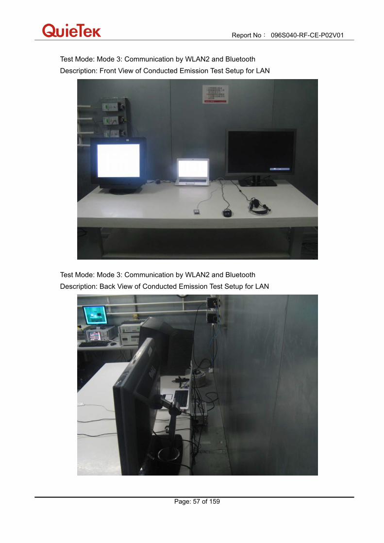
Test Mode: Mode 3: Communication by WLAN2 and Bluetooth Description: Front View of Conducted Emission Test Setup for LAN
Test Mode: Mode 3: Communication by WLAN2 and Bluetooth Description: Back View of Conducted Emission Test Setup for LAN

Report No: 096S040-RF-CE-P02V01
Page: 58 of 159
6. Radiated Emission
6.1. Test Specification According to EMC Standard: EN 55022 Class B
6.2. Test Setup
Below 1GHz Test Setup:
Above 1GHz Test Setup:

Report No: 096S040-RF-CE-P02V01
Page: 59 of 159
6.3. Limit
Limits for radiated emissions from ancillary equipment intended for use in telecommunication centres only, and measured on a stand alone basis
Frequency (MHz)
Distance (m)
QP (dBuV/m)
30 - 230 10 40
230 - 1000 10 47
Limits Above 1GHz for radiated emissions from ancillary equipment intended for
use in telecommunication centres only, and measured on a stand alone basis
Frequency (GHz)
Distance (m)
Average (dBuV/m)
Peak (dBuV/m)
1 - 3 3 56 76
3 - 6 3 60 80
Note 1: The lower limit shall apply at the transition frequency. Note 2: Distance refers to the distance in meters between the measuring instrument antenna
and the closed point of any part of the device or system.
Report No: 096S040-RF-CE-P02V01
Page: 60 of 159
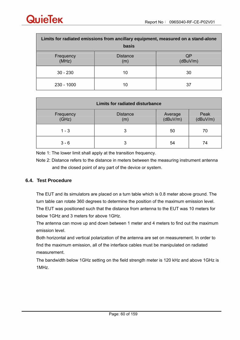
Limits for radiated emissions from ancillary equipment, measured on a stand-alone basis
Frequency (MHz)
Distance (m)
QP (dBuV/m)
30 - 230 10 30
230 - 1000 10 37
Limits for radiated disturbance
Frequency (GHz)
Distance (m)
Average (dBuV/m)
Peak (dBuV/m)
1 - 3 3 50 70
3 - 6 3 54 74
Note 1: The lower limit shall apply at the transition frequency. Note 2: Distance refers to the distance in meters between the measuring instrument antenna
and the closed point of any part of the device or system.
6.4. Test Procedure The EUT and its simulators are placed on a turn table which is 0.8 meter above ground. The turn table can rotate 360 degrees to determine the position of the maximum emission level. The EUT was positioned such that the distance from antenna to the EUT was 10 meters for below 1GHz and 3 meters for above 1GHz. The antenna can move up and down between 1 meter and 4 meters to find out the maximum emission level. Both horizontal and vertical polarization of the antenna are set on measurement. In order to find the maximum emission, all of the interface cables must be manipulated on radiated measurement.
The bandwidth below 1GHz setting on the field strength meter is 120 kHz and above 1GHz is 1MHz.

Report No: 096S040-RF-CE-P02V01
Page: 61 of 159
Conditional testing procedure: The highest internal source of an EUT is defined as the highest frequency generated or used within the EUT or on which the EUT operates or tunes.
Highest frequency generated or used in the device or on which the device operates or tunes
(MHz)
Upper frequency of measurement range (MHz)
< 108 1000
108 - 500 2000
500 - 1000 5000
Above 1000 5th harmonic of the highest frequency or 6
GHz, whichever is less
6.5. Deviation from Test Standard
No deviation.

Report No: 096S040-RF-CE-P02V01
Page: 62 of 159
6.6. Test Result Engineer : Seven
Site : AC-1 (10m Semi-Anechoic Chamber) Time : 2009/06/03 - 20:04
Limit : EN55022_B_10M_QP Margin : 6
EUT : Notebook PC Probe : CBL6112B_2931(30-1000MHz) - HORIZONTAL
Power : AC 230V/50Hz Note : Mode 1: Communication by WLAN1 and
Bluetooth
Frequency
(MHz)
Correct Factor
(dB)
Reading Level
(dBuV)
Measure Level
(dBuV/m)
Margin
(dB)
Limit
(dBuV/m)
Detector Type Ant Pos
(cm)
Table Pos
(deg)
1 59.100 -26.770 45.866 19.096 -10.904 30.000 QUASIPEAK 387.200 359.400
2 66.375 -27.040 47.475 20.435 -9.565 30.000 QUASIPEAK 220.300 200.300
3 102.750 -21.270 43.055 21.785 -8.215 30.000 QUASIPEAK 126.500 360.000
4 240.975 -19.570 48.565 28.995 -8.005 37.000 QUASIPEAK 100.000 165.200
5 265.225 -17.765 45.585 27.820 -9.180 37.000 QUASIPEAK 100.000 59.700
6 * 721.125 -7.890 37.544 29.654 -7.346 37.000 QUASIPEAK 100.000 260.300
Note: 1. All Readings below 1GHz are Quasi-Peak, above are performed with peak and/or average measurements as necessary. 2. " * ", means this data is the worst emission level. 3. Measurement Level = Reading Level + Correct Factor

Report No: 096S040-RF-CE-P02V01
Page: 63 of 159
Engineer : Seven
Site : AC-1 (10m Semi-Anechoic Chamber) Time : 2009/06/03 - 20:04
Limit : EN55022_B_10M_QP Margin : 6
EUT : Notebook PC Probe : CBL6112B_2933(30-1000MHz) - VERTICAL
Power : AC 230V/50Hz Note : Mode 1: Communication by WLAN1 and
Bluetooth
Frequency
(MHz)
Correct Factor
(dB)
Reading Level
(dBuV)
Measure Level
(dBuV/m)
Margin
(dB)
Limit
(dBuV/m)
Detector Type Ant Pos
(cm)
Table Pos
(deg)
1 37.275 -17.830 41.352 23.522 -6.478 30.000 QUASIPEAK 168.500 205.300
2 59.100 -26.600 48.518 21.918 -8.082 30.000 QUASIPEAK 315.600 43.200
3 66.375 -26.890 46.626 19.736 -10.264 30.000 QUASIPEAK 352.100 123.600
4 93.050 -22.720 46.068 23.348 -6.652 30.000 QUASIPEAK 309.200 275.100
5 265.225 -17.190 44.816 27.626 -9.374 37.000 QUASIPEAK 100.000 263.500
6 * 759.925 -7.205 37.889 30.684 -6.316 37.000 QUASIPEAK 100.000 25.300
Note: 1. All Readings below 1GHz are Quasi-Peak, above are performed with peak and/or average measurements as necessary. 2. " * ", means this data is the worst emission level. 3. Measurement Level = Reading Level + Correct Factor

Report No: 096S040-RF-CE-P02V01
Page: 64 of 159
Engineer : Seven
Site : AC-5 (3m Semi-Anechoic Chamber) Time : 2009/06/03 - 21:31
Limit : EN55022_B_(Above_1G)_03M_PK Margin : 0
EUT : Notebook PC Probe : 9120D_499(1-18GHz) - HORIZONTAL
Power : AC 230V/50Hz Note : Mode 1: Communication by WLAN1 and
Bluetooth
Frequency
(MHz)
Correct Factor
(dB)
Reading Level
(dBuV)
Measure Level
(dBuV/m)
Margin
(dB)
Limit
(dBuV/m)
Detector Type Ant Pos
(cm)
Table Pos
(deg)
1 * 1050.000 -10.430 57.361 46.931 -23.069 70.000 PEAK 100.000 281.200
2 1345.000 -9.254 48.459 39.205 -30.795 70.000 PEAK 100.000 167.300
3 1600.000 -9.008 49.292 40.284 -29.716 70.000 PEAK 100.000 76.500
Note: 1. All Readings below 1GHz are Quasi-Peak, above are performed with peak and/or average measurements as necessary. 2. " * ", means this data is the worst emission level. 3. Measurement Level = Reading Level + Correct Factor. 4. The average measurement was not performed when the peak measured data under the limit of average detection. If the readings given are average, peak measurement should also be supplied.

Report No: 096S040-RF-CE-P02V01
Page: 65 of 159
Engineer : Seven
Site : AC-5 (3m Semi-Anechoic Chamber) Time : 2009/06/03 - 21:31
Limit : EN55022_B_(Above_1G)_03M_AV Margin : 0
EUT : Notebook PC Probe : 9120D_499(1-18GHz) - HORIZONTAL
Power : AC 230V/50Hz Note : Mode 1: Communication by WLAN1 and
Bluetooth
Frequency
(MHz)
Correct Factor
(dB)
Reading Level
(dBuV)
Measure Level
(dBuV/m)
Margin
(dB)
Limit
(dBuV/m)
Detector Type Ant Pos
(cm)
Table Pos
(deg)
1 * 1050.000 -10.430 45.160 34.730 -15.270 50.000 AVERAGE 100.000 281.200
2 1345.000 -9.254 34.920 25.666 -24.334 50.000 AVERAGE 100.000 167.300
3 1600.000 -9.008 36.290 27.282 -22.718 50.000 AVERAGE 100.000 76.500
Note: 1. All Readings below 1GHz are Quasi-Peak, above are performed with peak and/or average measurements as necessary. 2. " * ", means this data is the worst emission level. 3. Measurement Level = Reading Level + Correct Factor. 4. The average measurement was not performed when the peak measured data under the limit of average detection. If the readings given are average, peak measurement should also be supplied.

Report No: 096S040-RF-CE-P02V01
Page: 66 of 159
Engineer : Seven
Site : AC-5 (3m Semi-Anechoic Chamber) Time : 2009/06/03 - 21:31
Limit : EN55022_B_(Above_1G)_03M_PK Margin : 0
EUT : Notebook PC Probe : 9120D_499(1-18GHz) - VERTICAL
Power : AC 230V/50Hz Note : Mode 1: Communication by WLAN1 and
Bluetooth
Frequency
(MHz)
Correct Factor
(dB)
Reading Level
(dBuV)
Measure Level
(dBuV/m)
Margin
(dB)
Limit
(dBuV/m)
Detector Type Ant Pos
(cm)
Table Pos
(deg)
1 1110.000 -10.322 60.588 50.266 -19.734 70.000 PEAK 100.000 318.200
2 1170.000 -10.218 60.872 50.654 -19.346 70.000 PEAK 100.000 149.700
3 * 1605.000 -9.005 64.750 55.745 -14.255 70.000 PEAK 100.000 349.600
Note: 1. All Readings below 1GHz are Quasi-Peak, above are performed with peak and/or average measurements as necessary. 2. " * ", means this data is the worst emission level. 3. Measurement Level = Reading Level + Correct Factor. 4. The average measurement was not performed when the peak measured data under the limit of average detection. If the readings given are average, peak measurement should also be supplied.
Report No: 096S040-RF-CE-P02V01
Page: 67 of 159
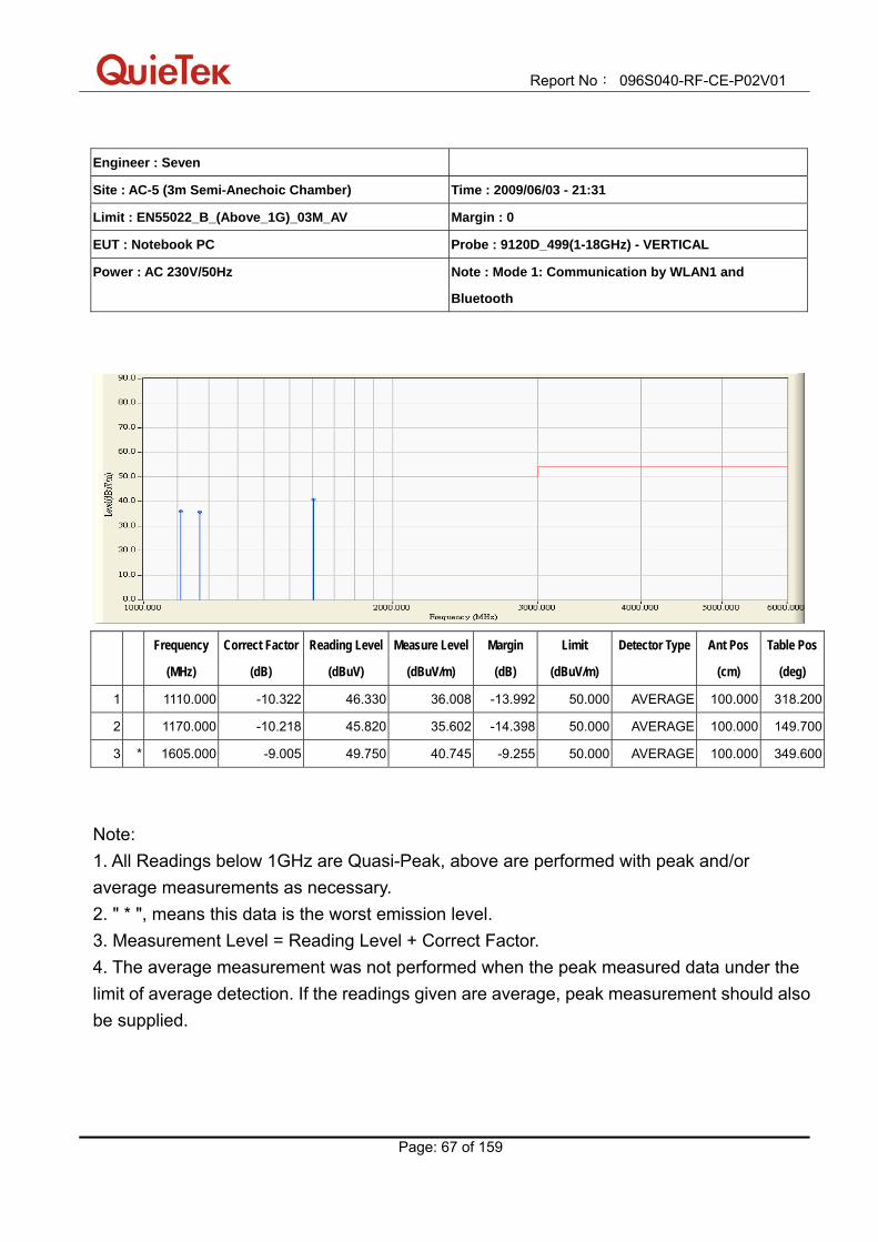
Engineer : Seven
Site : AC-5 (3m Semi-Anechoic Chamber) Time : 2009/06/03 - 21:31
Limit : EN55022_B_(Above_1G)_03M_AV Margin : 0
EUT : Notebook PC Probe : 9120D_499(1-18GHz) - VERTICAL
Power : AC 230V/50Hz Note : Mode 1: Communication by WLAN1 and
Bluetooth
Frequency
(MHz)
Correct Factor
(dB)
Reading Level
(dBuV)
Measure Level
(dBuV/m)
Margin
(dB)
Limit
(dBuV/m)
Detector Type Ant Pos
(cm)
Table Pos
(deg)
1 1110.000 -10.322 46.330 36.008 -13.992 50.000 AVERAGE 100.000 318.200
2 1170.000 -10.218 45.820 35.602 -14.398 50.000 AVERAGE 100.000 149.700
3 * 1605.000 -9.005 49.750 40.745 -9.255 50.000 AVERAGE 100.000 349.600
Note: 1. All Readings below 1GHz are Quasi-Peak, above are performed with peak and/or average measurements as necessary. 2. " * ", means this data is the worst emission level. 3. Measurement Level = Reading Level + Correct Factor. 4. The average measurement was not performed when the peak measured data under the limit of average detection. If the readings given are average, peak measurement should also be supplied.
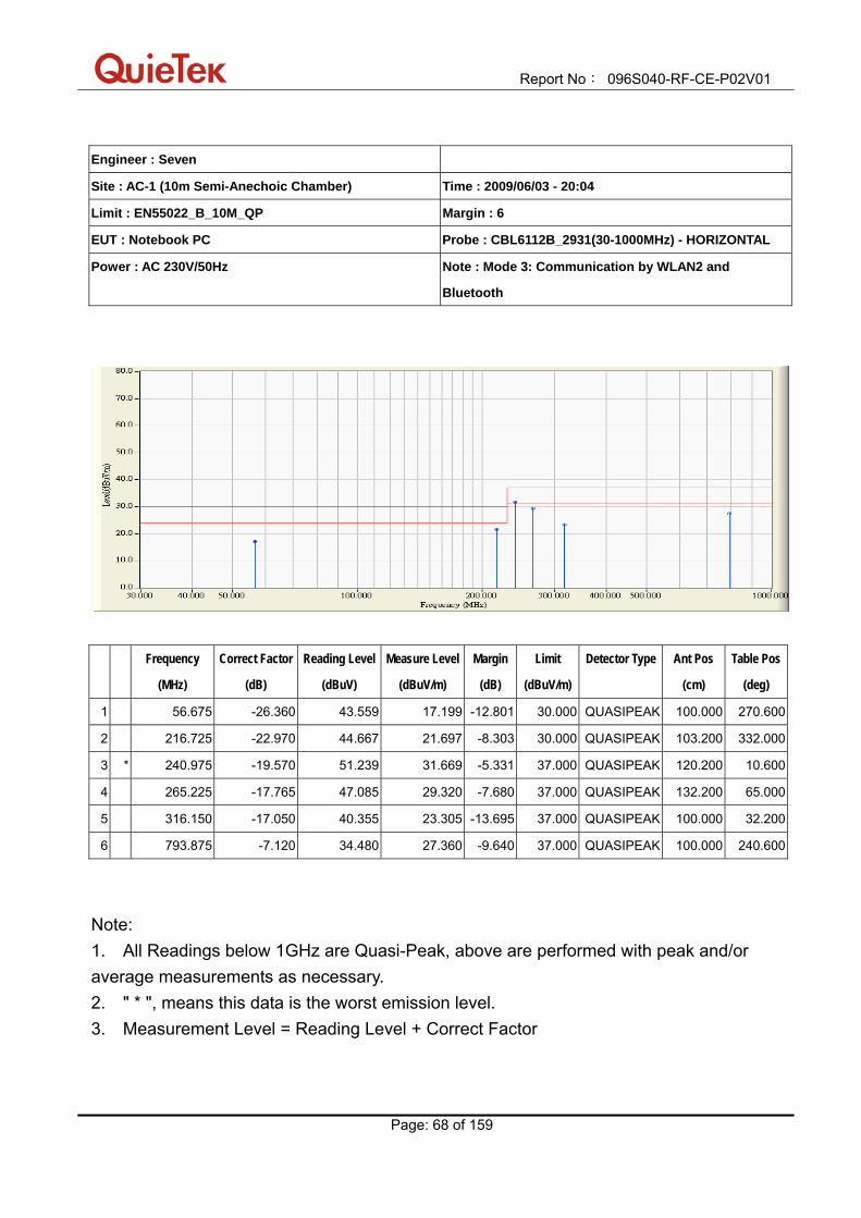
Report No: 096S040-RF-CE-P02V01
Page: 68 of 159
Engineer : Seven
Site : AC-1 (10m Semi-Anechoic Chamber) Time : 2009/06/03 - 20:04
Limit : EN55022_B_10M_QP Margin : 6
EUT : Notebook PC Probe : CBL6112B_2931(30-1000MHz) - HORIZONTAL
Power : AC 230V/50Hz Note : Mode 3: Communication by WLAN2 and
Bluetooth
Frequency
(MHz)
Correct Factor
(dB)
Reading Level
(dBuV)
Measure Level
(dBuV/m)
Margin
(dB)
Limit
(dBuV/m)
Detector Type Ant Pos
(cm)
Table Pos
(deg)
1 56.675 -26.360 43.559 17.199 -12.801 30.000 QUASIPEAK 100.000 270.600
2 216.725 -22.970 44.667 21.697 -8.303 30.000 QUASIPEAK 103.200 332.000
3 * 240.975 -19.570 51.239 31.669 -5.331 37.000 QUASIPEAK 120.200 10.600
4 265.225 -17.765 47.085 29.320 -7.680 37.000 QUASIPEAK 132.200 65.000
5 316.150 -17.050 40.355 23.305 -13.695 37.000 QUASIPEAK 100.000 32.200
6 793.875 -7.120 34.480 27.360 -9.640 37.000 QUASIPEAK 100.000 240.600
Note: 1. All Readings below 1GHz are Quasi-Peak, above are performed with peak and/or average measurements as necessary. 2. " * ", means this data is the worst emission level. 3. Measurement Level = Reading Level + Correct Factor

Report No: 096S040-RF-CE-P02V01
Page: 69 of 159
Engineer : Seven
Site : AC-1 (10m Semi-Anechoic Chamber) Time : 2009/06/03 - 20:04
Limit : EN55022_B_10M_QP Margin : 6
EUT : Notebook PC Probe : CBL6112B_2933(30-1000MHz) - VERTICAL
Power : AC 230V/50Hz Note : Mode 3: Communication by WLAN2 and
Bluetooth
Frequency
(MHz)
Correct Factor
(dB)
Reading Level
(dBuV)
Measure Level
(dBuV/m)
Margin
(dB)
Limit
(dBuV/m)
Detector Type Ant Pos
(cm)
Table Pos
(deg)
1 37.275 -17.830 39.463 21.633 -8.367 30.000 QUASIPEAK 356.200 214.000
2 83.350 -24.550 45.607 21.057 -8.943 30.000 QUASIPEAK 400.000 265.000
3 93.050 -22.720 44.462 21.742 -8.258 30.000 QUASIPEAK 400.000 325.100
4 240.975 -19.170 46.672 27.502 -9.498 37.000 QUASIPEAK 216.000 21.000
5 265.225 -17.190 45.209 28.019 -8.981 37.000 QUASIPEAK 168.000 320.000
6 * 781.750 -6.660 37.392 30.732 -6.268 37.000 QUASIPEAK 155.200 112.300
Note: 1. All Readings below 1GHz are Quasi-Peak, above are performed with peak and/or average measurements as necessary. 2. " * ", means this data is the worst emission level. 3. Measurement Level = Reading Level + Correct Factor

Report No: 096S040-RF-CE-P02V01
Page: 70 of 159
Engineer : Seven
Site : AC-5 (3m Semi-Anechoic Chamber) Time : 2009/06/03 - 21:31
Limit : EN55022_B_(Above_1G)_03M_PK Margin : 0
EUT : Notebook PC Probe : 9120D_499(1-18GHz) - HORIZONTAL
Power : AC 230V/50Hz Note : Mode 3: Communication by WLAN2 and
Bluetooth
Frequency
(MHz)
Correct Factor
(dB)
Reading Level
(dBuV)
Measure Level
(dBuV/m)
Margin
(dB)
Limit
(dBuV/m)
Detector Type Ant Pos
(cm)
Table Pos
(deg)
1 * 1050.000 -10.430 51.964 41.534 -28.466 70.000 PEAK 100.000 214.500
2 1245.000 -9.865 46.166 36.301 -33.699 70.000 PEAK 100.000 10.000
3 1640.000 -9.002 44.896 35.894 -34.106 70.000 PEAK 100.000 291.600
Note: 1. All Readings below 1GHz are Quasi-Peak, above are performed with peak and/or average measurements as necessary. 2. " * ", means this data is the worst emission level. 3. Measurement Level = Reading Level + Correct Factor. 4. The average measurement was not performed when the peak measured data under the limit of average detection. If the readings given are average, peak measurement should also be supplied.

Report No: 096S040-RF-CE-P02V01
Page: 71 of 159
Engineer : Seven
Site : AC-5 (3m Semi-Anechoic Chamber) Time : 2009/06/03 - 21:31
Limit : EN55022_B_(Above_1G)_03M_AV Margin : 0
EUT : Notebook Probe : 9120D_499(1-18GHz) - HORIZONTAL
Power : AC 230V/50Hz Note : Mode 3: Communication by WLAN2 and
Bluetooth
Frequency
(MHz)
Correct Factor
(dB)
Reading Level
(dBuV)
Measure Level
(dBuV/m)
Margin
(dB)
Limit
(dBuV/m)
Detector Type Ant Pos
(cm)
Table Pos
(deg)
1 * 1050.000 -10.430 36.450 26.020 -23.980 50.000 AVERAGE 100.000 214.500
2 1245.000 -9.865 31.350 21.485 -28.515 50.000 AVERAGE 100.000 10.000
3 1640.000 -9.002 30.600 21.598 -28.402 50.000 AVERAGE 100.000 291.600
Note: 1. All Readings below 1GHz are Quasi-Peak, above are performed with peak and/or average measurements as necessary. 2. " * ", means this data is the worst emission level. 3. Measurement Level = Reading Level + Correct Factor. 4. The average measurement was not performed when the peak measured data under the limit of average detection. If the readings given are average, peak measurement should also be supplied.
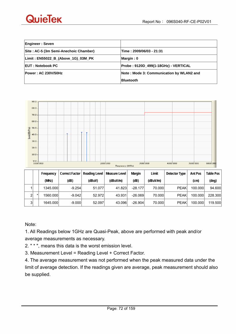
Report No: 096S040-RF-CE-P02V01
Page: 72 of 159
Engineer : Seven
Site : AC-5 (3m Semi-Anechoic Chamber) Time : 2009/06/03 - 21:31
Limit : EN55022_B_(Above_1G)_03M_PK Margin : 0
EUT : Notebook PC Probe : 9120D_499(1-18GHz) - VERTICAL
Power : AC 230V/50Hz Note : Mode 3: Communication by WLAN2 and
Bluetooth
Frequency
(MHz)
Correct Factor
(dB)
Reading Level
(dBuV)
Measure Level
(dBuV/m)
Margin
(dB)
Limit
(dBuV/m)
Detector Type Ant Pos
(cm)
Table Pos
(deg)
1 1345.000 -9.254 51.077 41.823 -28.177 70.000 PEAK 100.000 94.600
2 * 1560.000 -9.042 52.972 43.931 -26.069 70.000 PEAK 100.000 228.300
3 1645.000 -9.000 52.097 43.096 -26.904 70.000 PEAK 100.000 119.500
Note: 1. All Readings below 1GHz are Quasi-Peak, above are performed with peak and/or average measurements as necessary. 2. " * ", means this data is the worst emission level. 3. Measurement Level = Reading Level + Correct Factor. 4. The average measurement was not performed when the peak measured data under the limit of average detection. If the readings given are average, peak measurement should also be supplied.

Report No: 096S040-RF-CE-P02V01
Page: 73 of 159
Engineer : Seven
Site : AC-5 (3m Semi-Anechoic Chamber) Time : 2009/06/03 - 21:31
Limit : EN55022_B_(Above_1G)_03M_AV Margin : 0
EUT : Notebook PC Probe : 9120D_499(1-18GHz) - VERTICAL
Power : AC 230V/50Hz Note : Mode 3: Communication by WLAN2 and
Bluetooth
Frequency
(MHz)
Correct Factor
(dB)
Reading Level
(dBuV)
Measure Level
(dBuV/m)
Margin
(dB)
Limit
(dBuV/m)
Detector Type Ant Pos
(cm)
Table Pos
(deg)
1 1345.000 -9.254 36.310 27.056 -22.944 50.000 AVERAGE 100.000 94.600
2 1560.000 -9.042 37.590 28.549 -21.451 50.000 AVERAGE 100.000 228.300
3 * 1645.000 -9.000 38.510 29.509 -20.491 50.000 AVERAGE 100.000 119.500
Note: 1. All Readings below 1GHz are Quasi-Peak, above are performed with peak and/or average measurements as necessary. 2. " * ", means this data is the worst emission level. 3. Measurement Level = Reading Level + Correct Factor. 4. The average measurement was not performed when the peak measured data under the limit of average detection. If the readings given are average, peak measurement should also be supplied.

Report No: 096S040-RF-CE-P02V01
Page: 74 of 159
6.7. Test Photograph Test Mode : Mode 1: Communication by WLAN1 and Bluetooth Description : Front View of Radiated Emission Test Setup (Below 1GHz)
Test Mode : Mode 1: Communication by WLAN1 and Bluetooth Description : Back View of Radiated Emission Test Setup (Below 1GHz)

Report No: 096S040-RF-CE-P02V01
Page: 75 of 159
Test Mode : Mode 1: Communication by WLAN1 and Bluetooth Description : Front View of Radiated Emission Test Setup (Above 1GHz)
Test Mode : Mode 1: Communication by WLAN1 and Bluetooth Description : Back View of Radiated Emission Test Setup (Above 1GHz)

Report No: 096S040-RF-CE-P02V01
Page: 76 of 159
Test Mode : Mode 2: Communication by WLAN2 and Bluetooth Description : Front View of Radiated Emission Test Setup (Below 1GHz)
Test Mode : Mode 2: Communication by WLAN2 and Bluetooth Description : Back View of Radiated Emission Test Setup (Below 1GHz)
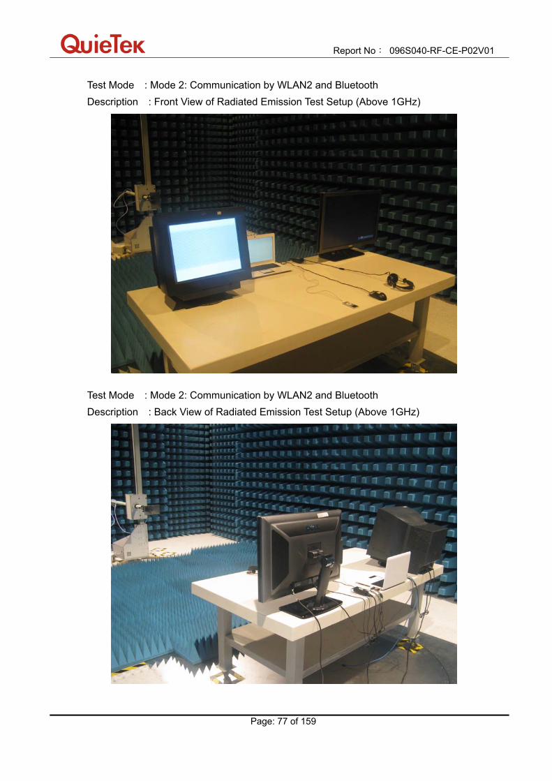
Report No: 096S040-RF-CE-P02V01
Page: 77 of 159
Test Mode : Mode 2: Communication by WLAN2 and Bluetooth Description : Front View of Radiated Emission Test Setup (Above 1GHz)
Test Mode : Mode 2: Communication by WLAN2 and Bluetooth Description : Back View of Radiated Emission Test Setup (Above 1GHz)
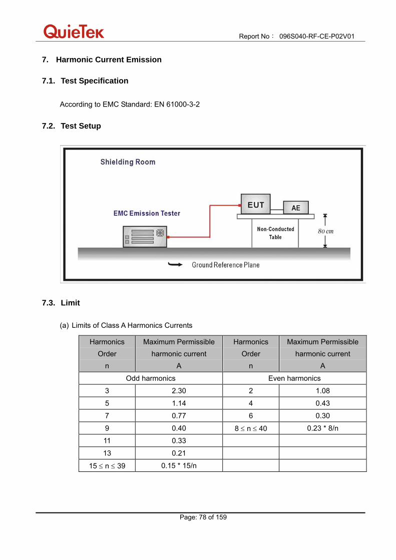
Report No: 096S040-RF-CE-P02V01
Page: 78 of 159
7. Harmonic Current Emission
7.1. Test Specification According to EMC Standard: EN 61000-3-2
7.2. Test Setup
7.3. Limit
(a) Limits of Class A Harmonics Currents
Harmonics Order
n
Maximum Permissible harmonic current
A
Harmonics Order
n
Maximum Permissible harmonic current
A
Odd harmonics Even harmonics
3 2.30 2 1.08
5 1.14 4 0.43
7 0.77 6 0.30
9 0.40 8 ≤ n ≤ 40 0.23 * 8/n
11 0.33
13 0.21
15 ≤ n ≤ 39 0.15 * 15/n

Report No: 096S040-RF-CE-P02V01
Page: 79 of 159
(b) Limits of Class B Harmonics Currents
For Class B equipment, the harmonic of the input current shall not exceed the maximum permissible values given in table that is the limit of Class A multiplied by a factor of 1.5.
(c) Limits of Class C Harmonics Currents
Harmonics Order
n
Maximum Permissible harmonic current Expressed as a percentage of the input current at the fundamental frequency
%
2 2
3 30.λ*
5 10
7 7
9 5
11 ≤ n ≤ 39 (odd harmonics only)
3
*λ is the circuit power factor
(d) Limits of Class D Harmonics Currents
Harmonics Order
n
Maximum Permissible harmonic current per watt
mA/W
Maximum Permissible harmonic current
A
3 3.4 2.30
5 1.9 1.14
7 1.0 0.77
9 0.5 0.40
11 0.35 0.33
11 ≤ n ≤ 39 (odd harmonics only)
3.85/n See limit of Class A

Report No: 096S040-RF-CE-P02V01
Page: 80 of 159
7.4. Test Procedure
The EUT is supplied in series with power analyzer from a power source having the same normal voltage and frequency as the rated supply voltage and the equipment under test. And the rated voltage at the supply voltage of EUT of 0.94 times and 1.06 times shall be performed.
7.5. Deviation from Test Standard No deviation.

Report No: 096S040-RF-CE-P02V01
Page: 81 of 159
7.6. Test Result Product Notebook PC
Test Item Harmonic Current Emission
Test Mode Mode 1: Communication by WLAN1 and Bluetooth
Date of Test 2009/06/03
Test Site SR-1
Test Result: Pass Source qualification: Normal
Current & voltage waveforms
-3-2-10123
-300-200-1000100200300
Cur
rent
(Am
ps)
Voltage (V
olts)
Harmonics and Class D limit line European Limits
0.0000.0250.0500.0750.1000.1250.1500.1750.200
Cur
rent
RM
S(A
mps
)
Harmonic #4 8 12 16 20 24 28 32 36 40
Test result: Pass

Report No: 096S040-RF-CE-P02V01
Page: 82 of 159
Test Result: N/L Source qualification: Normal THC(A): 0.00 I-THD(%): 0.00 POHC(A): 0.000 POHC Limit(A): 0.000 Highest parameter values during test:
V_RMS (Volts): 230.06 Frequency(Hz): 50.00 I_Peak (Amps): 2.667 I_RMS (Amps): 0.489 I_Fund (Amps): 0.174 Crest Factor: 5.717 Power (Watts): 39.5 Power Factor: 0.352
Harm# Harms(avg) 100%Limit %of Limit Harms(max) 150%Limit %of Limit Status 2 0.001 3 0.163 0.134 0.0 0.162 0.202 0.00 N/L 4 0.001 5 0.159 0.075 0.0 0.157 0.113 0.00 N/L 6 0.001 7 0.154 0.040 0.0 0.152 0.059 0.00 N/L 8 0.001 9 0.147 0.020 0.0 0.146 0.030 0.00 N/L 10 0.001 11 0.139 0.014 0.0 0.138 0.021 0.00 N/L 12 0.001 13 0.130 0.012 0.0 0.129 0.018 0.00 N/L 14 0.001 15 0.120 0.010 0.0 0.119 0.015 0.00 N/L 16 0.001 17 0.109 0.009 0.0 0.108 0.013 0.00 N/L 18 0.001 19 0.098 0.008 0.0 0.097 0.012 0.00 N/L 20 0.001 21 0.086 0.007 0.0 0.086 0.011 0.00 N/L 22 0.001 23 0.075 0.007 0.0 0.075 0.010 0.00 N/L 24 0.001 25 0.064 0.006 0.0 0.064 0.009 0.00 N/L 26 0.001 27 0.053 0.006 0.0 0.053 0.008 0.00 N/L 28 0.001 29 0.043 0.005 0.0 0.043 0.008 0.00 N/L 30 0.001 31 0.034 0.005 0.0 0.034 0.007 0.00 N/L 32 0.001 33 0.026 0.005 0.0 0.026 0.007 0.00 N/L 34 0.000 35 0.019 0.004 0.0 0.019 0.007 0.00 N/L 36 0.000 37 0.013 0.004 0.0 0.013 0.006 0.00 N/L 38 0.000 39 0.008 0.004 0.0 0.008 0.006 0.00 N/L 40 0.000
1. Dynamic limits were applied for this test. The highest harmonics values in the above table may
not occur at the same window as the maximum harmonics/limit ratio.
2. According to EN61000-3-2 paragraph 7 the note 1 and 2 are valid for all applications having an
active input power >75W. Others the result should be pass.

Report No: 096S040-RF-CE-P02V01
Page: 83 of 159
Product Notebook PC
Test Item Harmonic Current Emission
Test Mode Mode 3: Communication by WLAN2 and Bluetooth
Date of Test 2009/06/03
Test Site SR-1
Test Result: Pass Source qualification: Normal
Current & voltage waveforms
-3-2-10123
-300-200-1000100200300
Cur
rent
(Am
ps)
Voltage (V
olts)
Harmonics and Class D limit line European Limits
0.00
0.05
0.10
0.15
0.20
0.25
Cur
rent
RM
S(A
mps
)
Harmonic #4 8 12 16 20 24 28 32 36 40
Test result: Pass

Report No: 096S040-RF-CE-P02V01
Page: 84 of 159
Test Result: N/L Source qualification: Normal THC(A): 0.00 I-THD(%): 0.00 POHC(A): 0.000 POHC Limit(A): 0.000 Highest parameter values during test:
V_RMS (Volts): 230.05 Frequency(Hz): 50.00 I_Peak (Amps): 2.897 I_RMS (Amps): 0.568 I_Fund (Amps): 0.212 Crest Factor: 5.111 Power (Watts): 48.0 Power Factor: 0.368
Harm# Harms(avg) 100%Limit %of Limit Harms(max) 150%Limit %of Limit Status 2 0.002 3 0.204 0.163 0.0 0.206 0.245 0.00 N/L 4 0.001 5 0.199 0.091 0.0 0.200 0.137 0.00 N/L 6 0.001 7 0.191 0.048 0.0 0.192 0.072 0.00 N/L 8 0.000 9 0.181 0.024 0.0 0.182 0.036 0.00 N/L 10 0.001 11 0.169 0.017 0.0 0.170 0.025 0.00 N/L 12 0.001 13 0.155 0.014 0.0 0.156 0.021 0.00 N/L 14 0.000 15 0.140 0.012 0.0 0.142 0.018 0.00 N/L 16 0.000 17 0.125 0.011 0.0 0.126 0.016 0.00 N/L 18 0.000 19 0.109 0.010 0.0 0.110 0.015 0.00 N/L 20 0.000 21 0.093 0.009 0.0 0.094 0.013 0.00 N/L 22 0.000 23 0.078 0.008 0.0 0.078 0.012 0.00 N/L 24 0.000 25 0.063 0.007 0.0 0.064 0.011 0.00 N/L 26 0.000 27 0.049 0.007 0.0 0.050 0.010 0.00 N/L 28 0.000 29 0.037 0.006 0.0 0.037 0.010 0.00 N/L 30 0.000 31 0.026 0.006 0.0 0.026 0.009 0.00 N/L 32 0.000 33 0.017 0.006 0.0 0.017 0.008 0.00 N/L 34 0.000 35 0.009 0.005 0.0 0.009 0.008 0.00 N/L 36 0.000 37 0.004 0.005 0.0 0.004 0.007 0.00 N/L 38 0.000 39 0.004 0.005 0.0 0.004 0.007 0.00 N/L 40 0.000
1. Dynamic limits were applied for this test. The highest harmonics values in the above table may
not occur at the same window as the maximum harmonics/limit ratio.
2. According to EN61000-3-2 paragraph 7 the note 1 and 2 are valid for all applications having an
active input power >75W. Others the result should be pass.

Report No: 096S040-RF-CE-P02V01
Page: 85 of 159
7.7. Test Photograph Test Mode: Mode 1: Communication by WLAN1 and Bluetooth Description: Harmonic Current Emission Test Setup
Test Mode: Mode 3: Communication by WLAN2 and Bluetooth Description: Harmonic Current Emission Test Setup

Report No: 096S040-RF-CE-P02V01
Page: 86 of 159
8. Voltage Fluctuation and Flicker
8.1. Test Specification According to EMC Standard: EN 61000-3-3
8.2. Test Setup
8.3. Limit The following limits apply:
- the value of Pst shall not be greater than 1.0; - the value of Plt shall not be greater than 0.65; - the value of d(t) during a voltage change shall not exceed 3.3 % for more than 500 ms; - the relative steady-state voltage change, dc, shall not exceed 3.3 %; - the maximum relative voltage change, dmax, shall not exceed;
a) 4 % without additional conditions; b) 6 % for equipment which is:
- switched manually, or - switched automatically more frequently than twice per day, and also has either a
delayed restart (the delay being not less than a few tens of seconds), or manual restart, after a power supply interruption.
Note: The cycling frequency will be further limited by the Pst and P1t limit.
For example: a dmax of 6%producing a rectangular voltage change characteristic twice
per hour will give a P1t of about 0.65.

Report No: 096S040-RF-CE-P02V01
Page: 87 of 159
c) 7 % for equipment which is: - attended whilst in use (for example: hair dryers, vacuum cleaners, kitchen equipment
such as mixers, garden equipment such as lawn mowers, portable tools such as electric drills), or
- switched on automatically, or is intended to be switched on manually, no more than
twice per day, and also has either a delayed restart (the delay being not less than a few tens of seconds) or manual restart, after a power supply interruption.
Pst and P1t requirements shall not be applied to voltage changes caused by manual switching.
8.4. Test Procedure
The EUT is supplied in series with power analyzer from a power source having the same normal voltage and frequency as the rated supply voltage and the equipment under test. And the rated voltage at the supply voltage of EUT of 0.94 times and 1.06 times shall be performed.
8.5. Deviation from Test Standard No deviation.
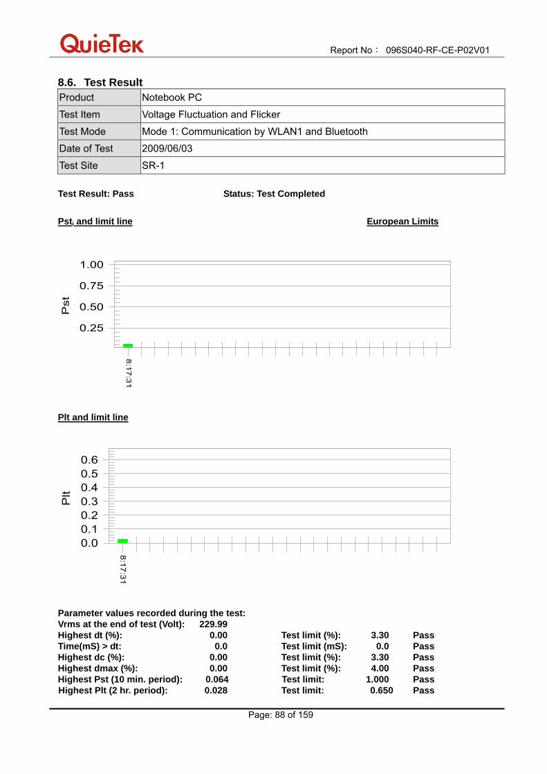
Report No: 096S040-RF-CE-P02V01
Page: 88 of 159
8.6. Test Result Product Notebook PC
Test Item Voltage Fluctuation and Flicker
Test Mode Mode 1: Communication by WLAN1 and Bluetooth
Date of Test 2009/06/03
Test Site SR-1
Test Result: Pass Status: Test Completed
Psti and limit line European Limits
0.25
0.50
0.75
1.00
Pst
8:1
7:3
1
Plt and limit line
0.00.10.20.30.40.50.6
Plt
8:17:31
Parameter values recorded during the test: Vrms at the end of test (Volt): 229.99 Highest dt (%): 0.00 Test limit (%): 3.30 Pass Time(mS) > dt: 0.0 Test limit (mS): 0.0 Pass Highest dc (%): 0.00 Test limit (%): 3.30 Pass Highest dmax (%): 0.00 Test limit (%): 4.00 Pass Highest Pst (10 min. period): 0.064 Test limit: 1.000 Pass Highest Plt (2 hr. period): 0.028 Test limit: 0.650 Pass

Report No: 096S040-RF-CE-P02V01
Page: 89 of 159
Product Notebook PC
Test Item Voltage Fluctuation and Flicker
Test Mode Mode 3: Communication by WLAN2 and Bluetooth
Date of Test 2009/06/03
Test Site SR-1
Test Result: Pass Status: Test Completed
Psti and limit line European Limits
0.25
0.50
0.75
1.00
Pst
7:5
3:0
2
Plt and limit line
0.00.10.20.30.40.50.6
Plt
7:53:02
Parameter values recorded during the test: Vrms at the end of test (Volt): 229.91 Highest dt (%): 0.00 Test limit (%): 3.30 Pass Time(mS) > dt: 0.0 Test limit (mS): 0.0 Pass Highest dc (%): 0.00 Test limit (%): 3.30 Pass Highest dmax (%): 0.00 Test limit (%): 4.00 Pass Highest Pst (10 min. period): 0.064 Test limit: 1.000 Pass Highest Plt (2 hr. period): 0.028 Test limit: 0.650 Pass

Report No: 096S040-RF-CE-P02V01
Page: 90 of 159
8.7. Test Photograph Test Mode : Mode 1: Communication by WLAN1 and Bluetooth Description : Voltage Fluctuation and Flicker Test Setup
Test Mode : Mode 3: Communication by WLAN2 and Bluetooth Description : Voltage Fluctuation and Flicker Test Setup

Report No: 096S040-RF-CE-P02V01
Page: 91 of 159
9. Electrostatic Discharge
9.1. Test Specification According to Standard: EN 61000-4-2
9.2. Test Setup
9.3. Limit
Item Environmental Phenomena
Units Test Specification Performance Criteria
Enclosure Port
Electrostatic Discharge kV(Charge Voltage) ±8 Air Discharge ±4 Contact Discharge
B
Report No: 096S040-RF-CE-P02V01
Page: 92 of 159
9.4. Test Procedure
Direct application of discharges to the EUT: Contact discharge was applied only to conductive surfaces of the EUT. Air discharges were applied only to non-conductive surfaces of the EUT. During the test, it was performed with single discharges. For the single discharge time between successive single discharges will be keep longer 1 second. It was at least ten single discharges with positive and negative at the same selected point. The selected point, which was performed with electrostatic discharge, was marked on the red label of the EUT.
Indirect application of discharges to the EUT:
Vertical Coupling Plane (VCP): The coupling plane, of dimensions 0.5m x 0.5m, is placed parallel to, and positioned at a distance 0.1m from, the EUT, with the Discharge Electrode touching the coupling plane. The four faces of the EUT will be performed with electrostatic discharge. It was at least ten single discharges with positive and negative at the same selected point. Horizontal Coupling Plane (HCP): The coupling plane is placed under to the EUT. The generator shall be positioned vertically at a distance of 0.1m from the EUT, with the Discharge Electrode touching the coupling plane. The four faces of the EUT will be performed with electrostatic discharge. It was at least ten single discharges with positive and negative at the same selected point.
9.5. Deviation from Test Standard
No deviation.
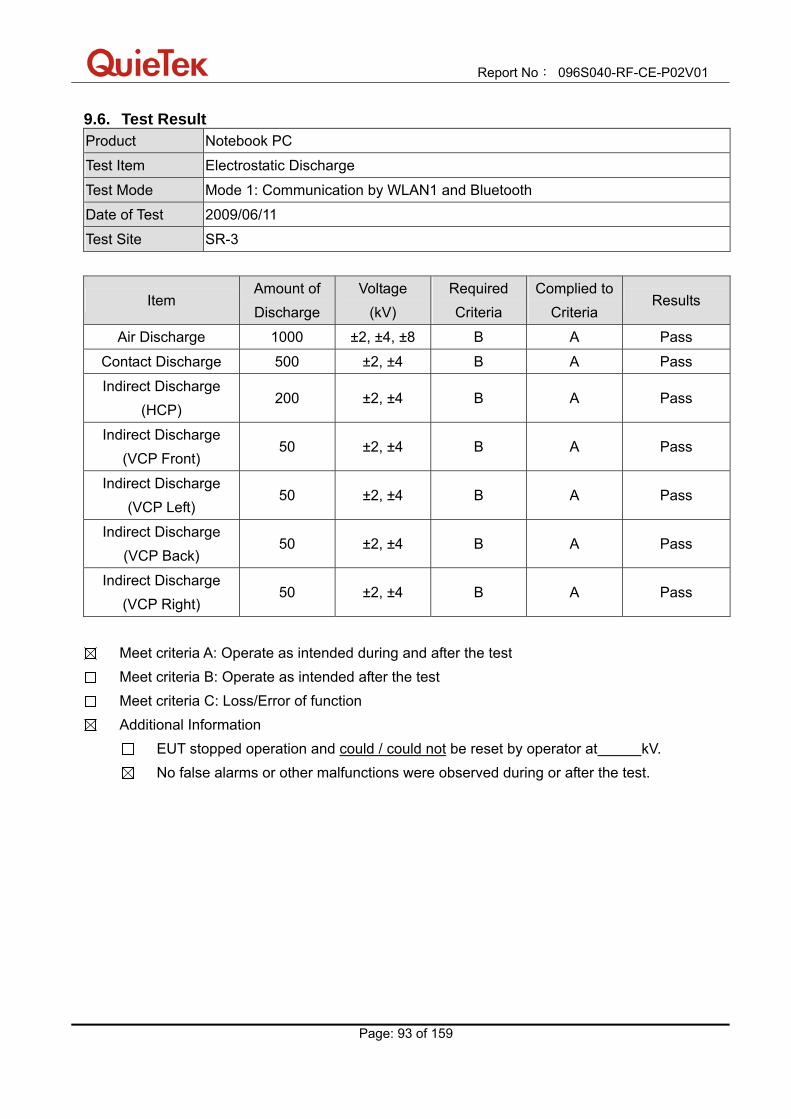
Report No: 096S040-RF-CE-P02V01
Page: 93 of 159
9.6. Test Result Product Notebook PC
Test Item Electrostatic Discharge
Test Mode Mode 1: Communication by WLAN1 and Bluetooth
Date of Test 2009/06/11
Test Site SR-3
Item Amount of Discharge
Voltage (kV)
Required Criteria
Complied to Criteria
Results
Air Discharge 1000 ±2, ±4, ±8 B A Pass
Contact Discharge 500 ±2, ±4 B A Pass
Indirect Discharge (HCP)
200 ±2, ±4 B A Pass
Indirect Discharge (VCP Front)
50 ±2, ±4 B A Pass
Indirect Discharge (VCP Left)
50 ±2, ±4 B A Pass
Indirect Discharge (VCP Back)
50 ±2, ±4 B A Pass
Indirect Discharge (VCP Right)
50 ±2, ±4 B A Pass
Meet criteria A: Operate as intended during and after the test Meet criteria B: Operate as intended after the test Meet criteria C: Loss/Error of function Additional Information
EUT stopped operation and could / could not be reset by operator at kV. No false alarms or other malfunctions were observed during or after the test.

Report No: 096S040-RF-CE-P02V01
Page: 94 of 159
Product Notebook PC
Test Item Electrostatic Discharge
Test Mode Mode 2: Standby
Date of Test 2009/06/11
Test Site SR-3
Item Amount of Discharge
Voltage (kV)
Required Criteria
Complied to Criteria
Results
Air Discharge 1000 ±2, ±4, ±8 B A Pass
Contact Discharge 500 ±2, ±4 B A Pass
Indirect Discharge (HCP)
200 ±2, ±4 B A Pass
Indirect Discharge (VCP Front)
50 ±2, ±4 B A Pass
Indirect Discharge (VCP Left)
50 ±2, ±4 B A Pass
Indirect Discharge (VCP Back)
50 ±2, ±4 B A Pass
Indirect Discharge (VCP Right)
50 ±2, ±4 B A Pass
Meet criteria A: Operate as intended during and after the test Meet criteria B: Operate as intended after the test Meet criteria C: Loss/Error of function Additional Information
EUT stopped operation and could / could not be reset by operator at kV. No false alarms or other malfunctions were observed during or after the test.

Report No: 096S040-RF-CE-P02V01
Page: 95 of 159
Product Notebook PC
Test Item Electrostatic Discharge
Test Mode Mode 3: Communication by WLAN2 and Bluetooth
Date of Test 2009/06/11
Test Site SR-3
Item Amount of Discharge
Voltage (kV)
Required Criteria
Complied to Criteria
Results
Air Discharge 1000 ±2, ±4, ±8 B A Pass
Contact Discharge 500 ±2, ±4 B A Pass
Indirect Discharge (HCP)
200 ±2, ±4 B A Pass
Indirect Discharge (VCP Front)
50 ±2, ±4 B A Pass
Indirect Discharge (VCP Left)
50 ±2, ±4 B A Pass
Indirect Discharge (VCP Back)
50 ±2, ±4 B A Pass
Indirect Discharge (VCP Right)
50 ±2, ±4 B A Pass
Meet criteria A: Operate as intended during and after the test Meet criteria B: Operate as intended after the test Meet criteria C: Loss/Error of function Additional Information
EUT stopped operation and could / could not be reset by operator at kV. No false alarms or other malfunctions were observed during or after the test.

Report No: 096S040-RF-CE-P02V01
Page: 96 of 159
Product Notebook PC
Test Item Electrostatic Discharge
Test Mode Mode 4: Standby
Date of Test 2009/06/11
Test Site SR-3
Item Amount of Discharge
Voltage (kV)
Required Criteria
Complied to Criteria
Results
Air Discharge 1000 ±2, ±4, ±8 B A Pass
Contact Discharge 500 ±2, ±4 B A Pass
Indirect Discharge (HCP)
200 ±2, ±4 B A Pass
Indirect Discharge (VCP Front)
50 ±2, ±4 B A Pass
Indirect Discharge (VCP Left)
50 ±2, ±4 B A Pass
Indirect Discharge (VCP Back)
50 ±2, ±4 B A Pass
Indirect Discharge (VCP Right)
50 ±2, ±4 B A Pass
Meet criteria A: Operate as intended during and after the test Meet criteria B: Operate as intended after the test Meet criteria C: Loss/Error of function Additional Information
EUT stopped operation and could / could not be reset by operator at kV. No false alarms or other malfunctions were observed during or after the test.

Report No: 096S040-RF-CE-P02V01
Page: 97 of 159
9.7. Test Photograph Test Mode: Mode 1: Communication by WLAN1 and Bluetooth Description: Electrostatic Discharge Test Setup
Test Mode: Mode 2: Standby Description: Electrostatic Discharge Test Setup

Report No: 096S040-RF-CE-P02V01
Page: 98 of 159
Test Mode: Mode 3: Communication by WLAN2 and Bluetooth Description: Electrostatic Discharge Test Setup
Test Mode: Mode 4: Standby Description: Electrostatic Discharge Test Setup

Report No: 096S040-RF-CE-P02V01
Page: 99 of 159
10. RF Electromagnetic Field
10.1. Test Specification
According to Standard: EN 61000-4-3
10.2. Test Setup
10.3. Limit
Item Environmental Phenomena
Units Test Specification Performance Criteria
Enclosure Port (See Note)
Radio-Frequency Electromagnetic Field Amplitude Modulated
MHz V/m(Un-modulated, rms)% AM (1kHz)
80-1000, 1400-2700 3 80
A

Report No: 096S040-RF-CE-P02V01
Page: 100 of 159
10.4. Test Procedure
The EUT and load, which are placed on a table that is 0.8 meter above ground, are placed with one coincident with the calibration plane such that the distance from antenna to the EUT was 3 meters. Both horizontal and vertical polarization of the antenna and four sides of the EUT are set on measurement. In order to judge the EUT performance, a CCD camera is used to monitor EUT screen.
All the scanning conditions are as follows: Condition of Test Remarks 1. Field Strength 3 V/m Level 2 2. Radiated Signal AM 80% Modulated with 1kHz 3. Scanning Frequency 80 - 1000MHz, 1400 – 2700MHz 4 Dwell Time 3 Seconds 5. Frequency step size ∆ f 1% 6. The rate of Swept of Frequency 1.5 x 10⁻³ decades/s
10.5. Deviation from Test Standard
No deviation.

Report No: 096S040-RF-CE-P02V01
Page: 101 of 159
10.6. Test Result Product Notebook PC
Test Item RF Electromagnetic Field
Test Mode Mode 1: Communication by WLAN1 and Bluetooth
Date of Test 2009/06/11
Test Site AC-4
Frequency (MHz)
Position (Angle)
Polarity (H or V)
Field Strength
(V/m)
Required Criteria
Complied to Criteria
Results
80-1000 1400-2700
Front H 3 A A Pass
80-1000 1400-2700
Front V 3 A A Pass
80-1000 1400-2700
Back H 3 A A Pass
80-1000 1400-2700
Back V 3 A A Pass
80-1000 1400-2700
Right H 3 A A Pass
80-1000 1400-2700
Right V 3 A A Pass
80-1000 1400-2700
Left H 3 A A Pass
80-1000 1400-2700
Left V 3 A A Pass
Meet criteria A: Operate as intended during and after the test Meet criteria B: Operate as intended after the test Meet criteria C: Loss/Error of function Additional Information
EUT stopped operation and could / could not be reset by operator at V/m, at frequency MHz.
No false alarms or other malfunctions were observed during or after the test.

Report No: 096S040-RF-CE-P02V01
Page: 102 of 159
Product Notebook PC
Test Item RF Electromagnetic Field
Test Mode Mode 2: Standby
Date of Test 2009/06/11
Test Site AC-4
Frequency (MHz)
Position (Angle)
Polarity (H or V)
Field Strength
(V/m)
Required Criteria
Complied to Criteria
Results
80-1000 1400-2700
Front H 3 A A Pass
80-1000 1400-2700
Front V 3 A A Pass
80-1000 1400-2700
Back H 3 A A Pass
80-1000 1400-2700
Back V 3 A A Pass
80-1000 1400-2700
Right H 3 A A Pass
80-1000 1400-2700
Right V 3 A A Pass
80-1000 1400-2700
Left H 3 A A Pass
80-1000 1400-2700
Left V 3 A A Pass
Meet criteria A: Operate as intended during and after the test Meet criteria B: Operate as intended after the test Meet criteria C: Loss/Error of function Additional Information
EUT stopped operation and could / could not be reset by operator at V/m, at frequency MHz.
No false alarms or other malfunctions were observed during or after the test.
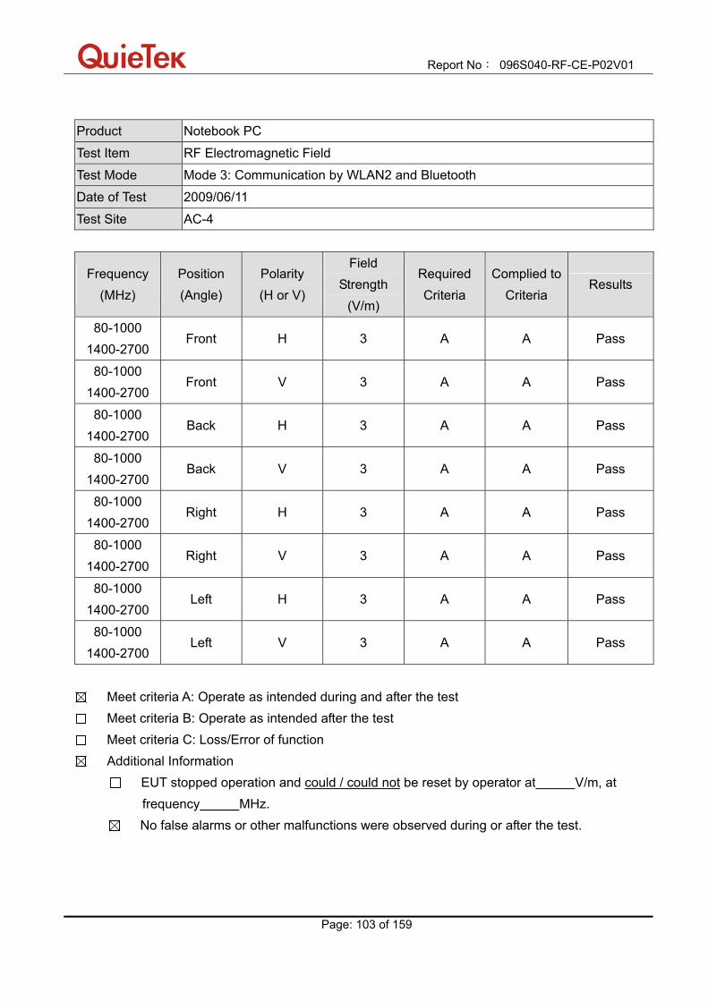
Report No: 096S040-RF-CE-P02V01
Page: 103 of 159
Product Notebook PC
Test Item RF Electromagnetic Field
Test Mode Mode 3: Communication by WLAN2 and Bluetooth
Date of Test 2009/06/11
Test Site AC-4
Frequency (MHz)
Position (Angle)
Polarity (H or V)
Field Strength
(V/m)
Required Criteria
Complied to Criteria
Results
80-1000 1400-2700
Front H 3 A A Pass
80-1000 1400-2700
Front V 3 A A Pass
80-1000 1400-2700
Back H 3 A A Pass
80-1000 1400-2700
Back V 3 A A Pass
80-1000 1400-2700
Right H 3 A A Pass
80-1000 1400-2700
Right V 3 A A Pass
80-1000 1400-2700
Left H 3 A A Pass
80-1000 1400-2700
Left V 3 A A Pass
Meet criteria A: Operate as intended during and after the test Meet criteria B: Operate as intended after the test Meet criteria C: Loss/Error of function Additional Information
EUT stopped operation and could / could not be reset by operator at V/m, at frequency MHz.
No false alarms or other malfunctions were observed during or after the test.
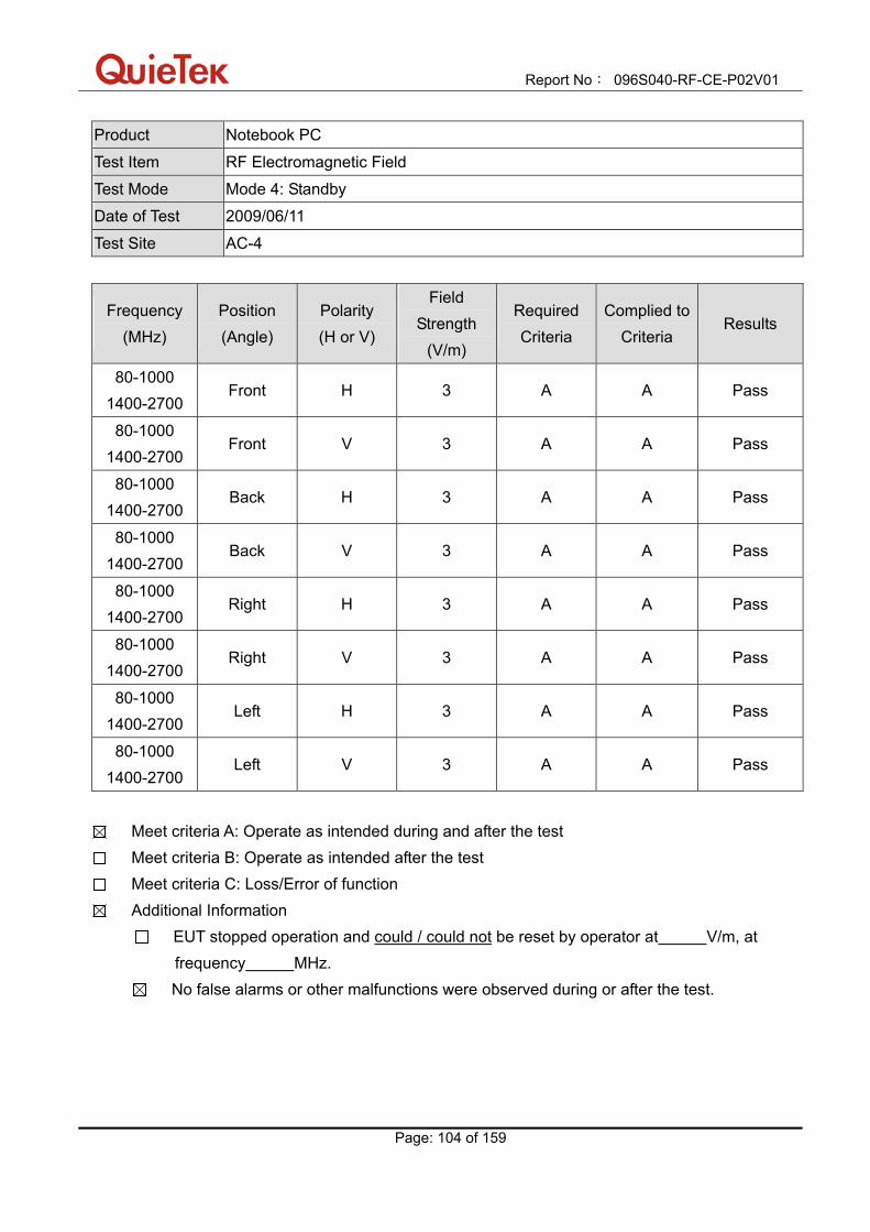
Report No: 096S040-RF-CE-P02V01
Page: 104 of 159
Product Notebook PC
Test Item RF Electromagnetic Field
Test Mode Mode 4: Standby
Date of Test 2009/06/11
Test Site AC-4
Frequency (MHz)
Position (Angle)
Polarity (H or V)
Field Strength
(V/m)
Required Criteria
Complied to Criteria
Results
80-1000 1400-2700
Front H 3 A A Pass
80-1000 1400-2700
Front V 3 A A Pass
80-1000 1400-2700
Back H 3 A A Pass
80-1000 1400-2700
Back V 3 A A Pass
80-1000 1400-2700
Right H 3 A A Pass
80-1000 1400-2700
Right V 3 A A Pass
80-1000 1400-2700
Left H 3 A A Pass
80-1000 1400-2700
Left V 3 A A Pass
Meet criteria A: Operate as intended during and after the test Meet criteria B: Operate as intended after the test Meet criteria C: Loss/Error of function Additional Information
EUT stopped operation and could / could not be reset by operator at V/m, at frequency MHz.
No false alarms or other malfunctions were observed during or after the test.
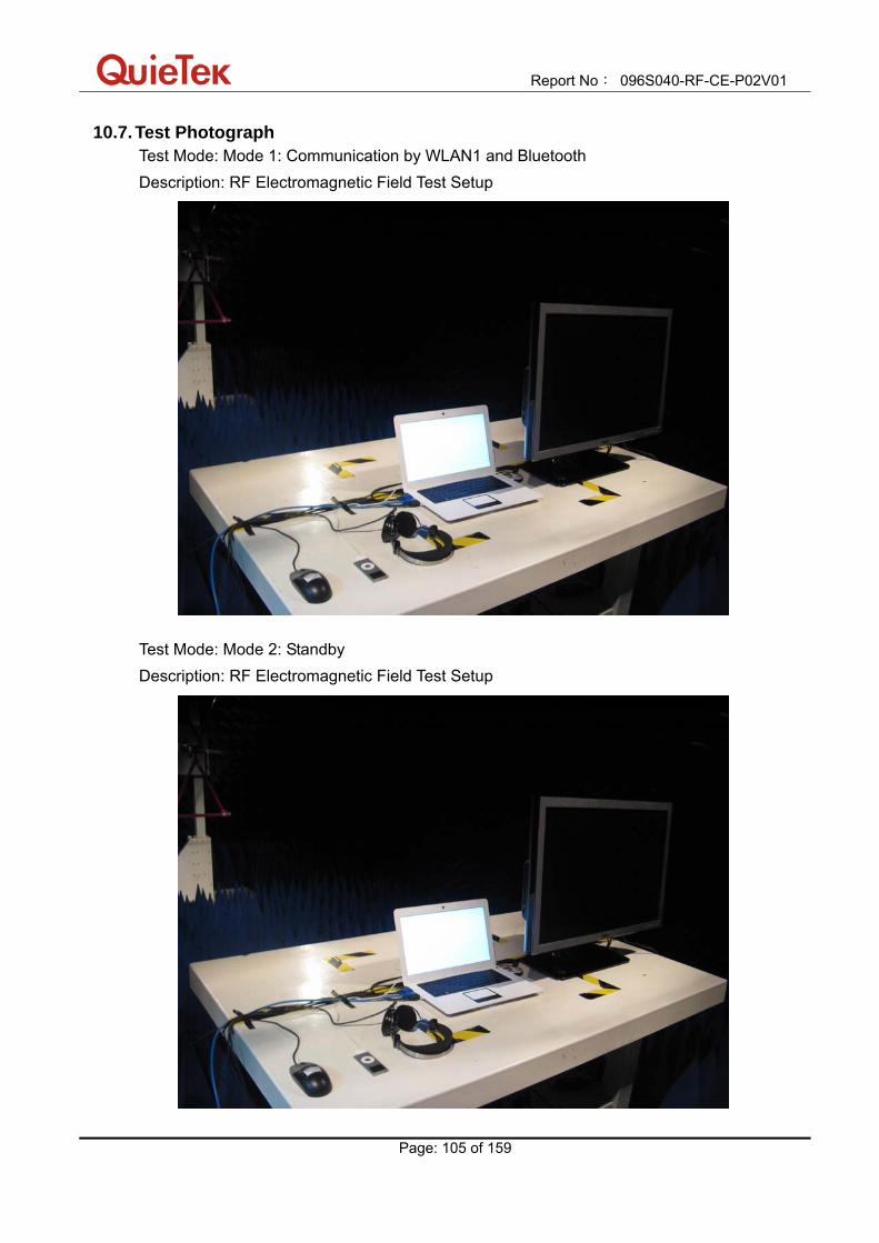
Report No: 096S040-RF-CE-P02V01
Page: 105 of 159
10.7. Test Photograph Test Mode: Mode 1: Communication by WLAN1 and Bluetooth Description: RF Electromagnetic Field Test Setup
Test Mode: Mode 2: Standby Description: RF Electromagnetic Field Test Setup
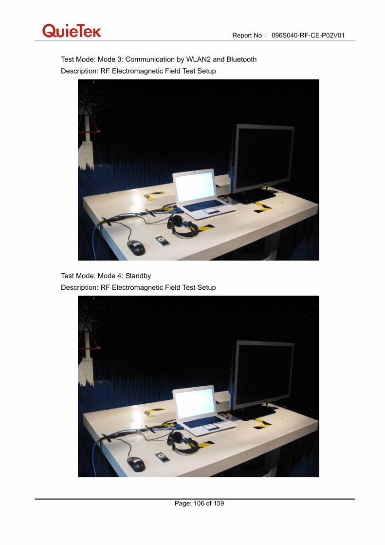
Report No: 096S040-RF-CE-P02V01
Page: 106 of 159
Test Mode: Mode 3: Communication by WLAN2 and Bluetooth Description: RF Electromagnetic Field Test Setup
Test Mode: Mode 4: Standby Description: RF Electromagnetic Field Test Setup

Report No: 096S040-RF-CE-P02V01
Page: 107 of 159
11. Fast Transients Common Mode
11.1. Test Specification According to Standard: EN 61000-4-4
11.2. Test Setup
11.3. Limit Item Environmental
Phenomena Units Test Specification Performance Criteria
Signal Ports and Telecommunication Ports (See Note) Fast Transients Common Mode
kV (Peak) Tr/Th ns Rep. Frequency kHz
+0.5 5/50 5
B
Input D.C. Power Ports Fast Transients Common Mode
kV (Peak) Tr/Th ns Rep. Frequency kHz
+0.5 5/50 5
B
Input A.C. Power Ports Fast Transients Common Mode
kV (Peak) Tr/Th ns Rep. Frequency kHz
+1 5/50 5
B
Note: Applicable only to cables which according to the manufacturer’s specification supports communication on cable lengths greater than 3m.

Report No: 096S040-RF-CE-P02V01
Page: 108 of 159
11.4. Test Procedure The EUT is placed on a table that is 0.8 meter height. A ground reference plane is placed on the table, and uses a 0.1m insulation between the EUT and ground reference plane. The minimum area of the ground reference plane is 1m*1m, and 0.65mm thick min, and projected beyond the EUT by at least 0.1m on all sides. For signal and telecommunication ports: The EFT interference signal is through a coupling clamp device couples to the signal and control lines of the EUT with burst noise for 1minute. For input A.C. and D.C. power ports: The EUT is connected to the power mains through a coupling device that directly couples the EFT/B interference signal. Each of the Line and Neutral conductors is impressed with burst noise for 1 minute. The length of the signal and power lines between the coupling device and the EUT is 0.5m.
11.5. Deviation from Test Standard No deviation.

Report No: 096S040-RF-CE-P02V01
Page: 109 of 159
11.6. Test Result Product Notebook PC
Test Item Fast Transients Common Mode
Test Mode Mode 1: Communication by WLAN1 and Bluetooth
Date of Test 2009/06/11
Test Site SR-2
Inject Line
Polarity Voltage
(kV)
Inject Time
(Second)
Inject Method
Required Criteria
Complied to Criteria
Result
L+N+PE ± 1 60 Direct B A Pass
LAN ± 0.5 60 Clamp B A Pass
Meet criteria A: Operate as intended during and after the test Meet criteria B: Operate as intended after the test Meet criteria C: Loss/Error of function Additional Information
EUT stopped operation and could / could not be reset by operator at kV of Line .
No false alarms or other malfunctions were observed during or after the test.

Report No: 096S040-RF-CE-P02V01
Page: 110 of 159
Product Notebook PC
Test Item Fast Transients Common Mode
Test Mode Mode 2: Standby
Date of Test 2009/06/11
Test Site SR-2
Inject Line
Polarity Voltage
(kV)
Inject Time
(Second)
Inject Method
Required Criteria
Complied to Criteria
Result
L+N+PE ± 1 60 Direct B A Pass
LAN ± 0.5 60 Clamp B A Pass
Meet criteria A: Operate as intended during and after the test Meet criteria B: Operate as intended after the test Meet criteria C: Loss/Error of function Additional Information
EUT stopped operation and could / could not be reset by operator at kV of Line .
No false alarms or other malfunctions were observed during or after the test.

Report No: 096S040-RF-CE-P02V01
Page: 111 of 159
Product Notebook PC
Test Item Fast Transients Common Mode
Test Mode Mode 3: Communication by WLAN2 and Bluetooth
Date of Test 2009/06/11
Test Site SR-2
Inject Line
Polarity Voltage
(kV)
Inject Time
(Second)
Inject Method
Required Criteria
Complied to Criteria
Result
L+N+PE ± 1 60 Direct B A Pass
LAN ± 0.5 60 Clamp B A Pass
Meet criteria A: Operate as intended during and after the test Meet criteria B: Operate as intended after the test Meet criteria C: Loss/Error of function Additional Information
EUT stopped operation and could / could not be reset by operator at kV of Line .
No false alarms or other malfunctions were observed during or after the test.
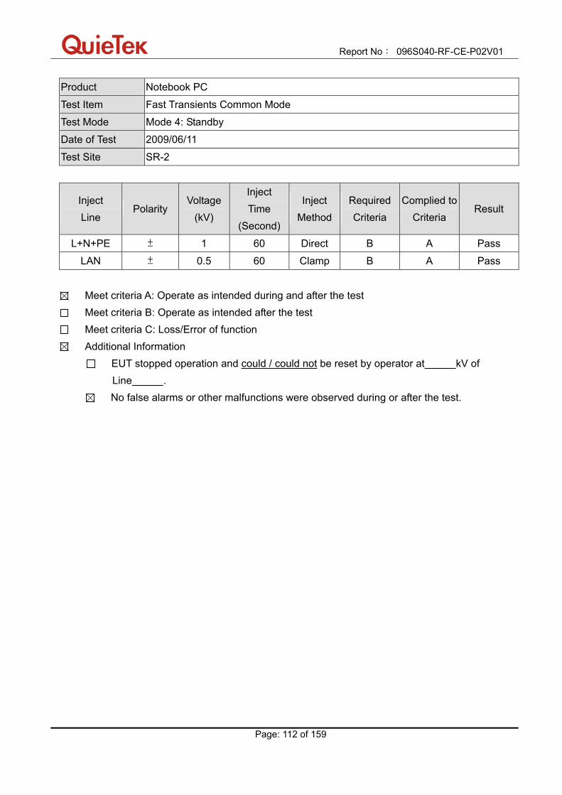
Report No: 096S040-RF-CE-P02V01
Page: 112 of 159
Product Notebook PC
Test Item Fast Transients Common Mode
Test Mode Mode 4: Standby
Date of Test 2009/06/11
Test Site SR-2
Inject Line
Polarity Voltage
(kV)
Inject Time
(Second)
Inject Method
Required Criteria
Complied to Criteria
Result
L+N+PE ± 1 60 Direct B A Pass
LAN ± 0.5 60 Clamp B A Pass
Meet criteria A: Operate as intended during and after the test Meet criteria B: Operate as intended after the test Meet criteria C: Loss/Error of function Additional Information
EUT stopped operation and could / could not be reset by operator at kV of Line .
No false alarms or other malfunctions were observed during or after the test.

Report No: 096S040-RF-CE-P02V01
Page: 113 of 159
11.7. Test Photograph Test Mode: Mode 1: Communication by WLAN1 and Bluetooth Description: Fast Transients Common Mode Test Setup for Main
Test Mode: Mode 1: Communication by WLAN1 and Bluetooth Description: Fast Transients Common Mode Test Setup for LAN

Report No: 096S040-RF-CE-P02V01
Page: 114 of 159
Test Mode: Mode 2: Standby Description: Fast Transients Common Mode Test Setup for Main
Test Mode: Mode 2: Standby Description: Fast Transients Common Mode Test Setup for LAN

Report No: 096S040-RF-CE-P02V01
Page: 115 of 159
Test Mode: Mode 3: Communication by WLAN2 and Bluetooth Description: Fast Transients Common Mode Test Setup for Main
Test Mode: Mode 3: Communication by WLAN2 and Bluetooth Description: Fast Transients Common Mode Test Setup for LAN
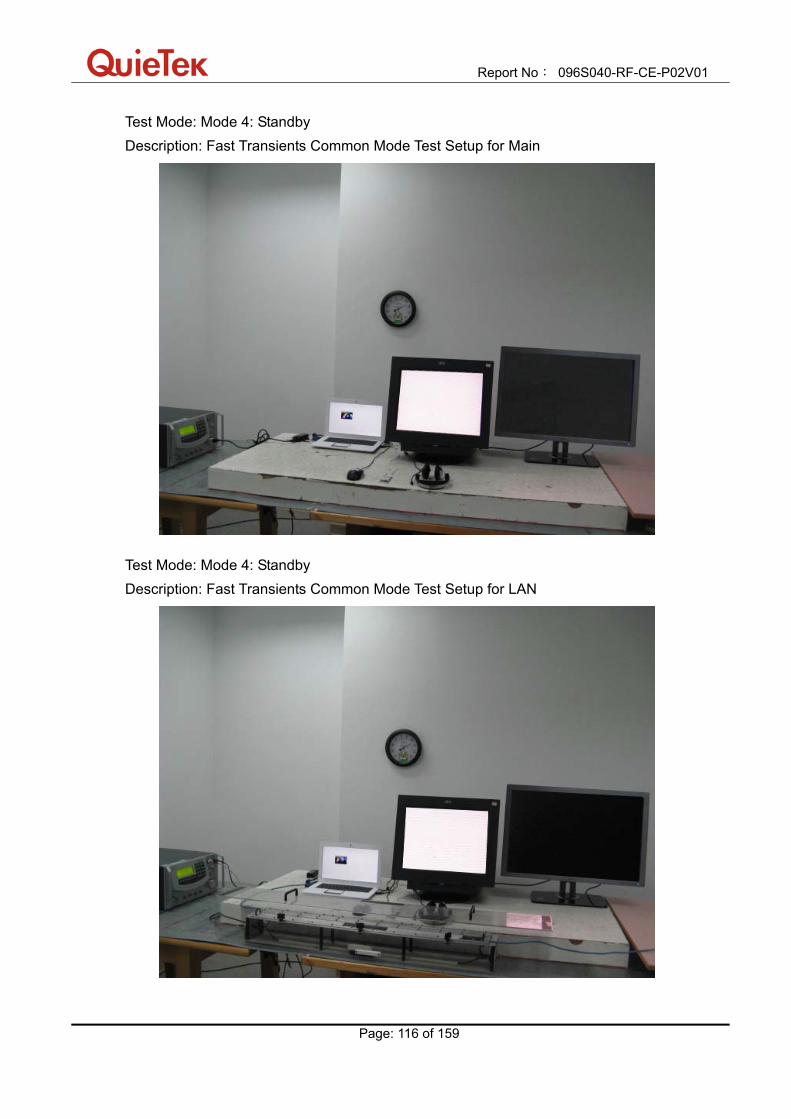
Report No: 096S040-RF-CE-P02V01
Page: 116 of 159
Test Mode: Mode 4: Standby Description: Fast Transients Common Mode Test Setup for Main
Test Mode: Mode 4: Standby Description: Fast Transients Common Mode Test Setup for LAN
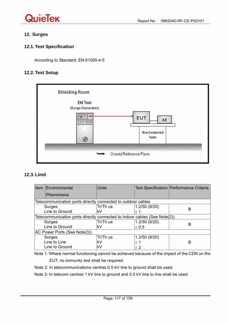
Report No: 096S040-RF-CE-P02V01
Page: 117 of 159
12. Surges
12.1. Test Specification According to Standard: EN 61000-4-5
12.2. Test Setup
12.3. Limit Item Environmental
Phenomena Units Test Specification Performance Criteria
Telecommunication ports directly connected to outdoor cables Surges Line to Ground
Tr/Th us kV
1.2/50 (8/20) ± 1 B
Telecommunication ports directly connected to indoor cables (See Note(2)) Surges Line to Ground
Tr/Th us kV
1.2/50 (8/20) ± 0.5 B
AC Power Ports (See Note(3)) Surges Line to Line Line to Ground
Tr/Th us kV kV
1.2/50 (8/20) ± 1 ± 2
B
Note 1: Where normal functioning cannot be achieved because of the impact of the CDN on the EUT, no immunity test shall be required.
Note 2: In telecommunications centres 0.5 kV line to ground shall be used. Note 3: In telecom centres 1 kV line to ground and 0.5 kV line to line shall be used.
Report No: 096S040-RF-CE-P02V01
Page: 118 of 159
12.4. Test Procedure The EUT and its load are placed on a table that is 0.8 meter above a metal ground plane measured 1m*1m min. and 0.65mm thick min. And projected beyond the EUT by at least 0.1m on all sides. The length of power cord between the coupling device and the EUT shall be 2m or less. For input A.C. and D.C. power ports: The EUT is connected to the power mains through a coupling device that directly couples the Surge interference signal. The surge noise shall be applied synchronized to the voltage phase at 00, 900, 1800, 2700 and the peak value of the a.c. voltage wave. (Positive and negative) Each of Line-Earth and Line-Line is impressed with a sequence of five surge voltages with interval of 1 min.
12.5. Deviation from Test Standard No deviation.
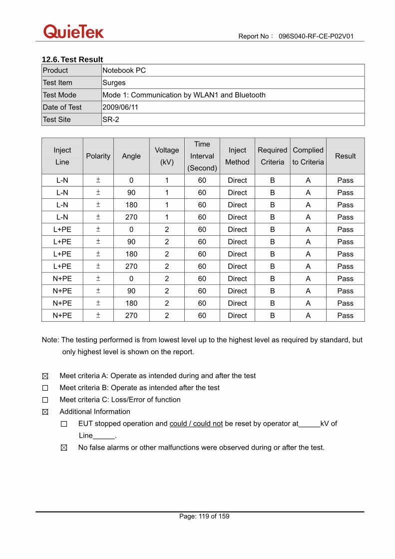
Report No: 096S040-RF-CE-P02V01
Page: 119 of 159
12.6. Test Result Product Notebook PC
Test Item Surges
Test Mode Mode 1: Communication by WLAN1 and Bluetooth
Date of Test 2009/06/11
Test Site SR-2
Inject Line
Polarity Angle Voltage
(kV)
Time Interval
(Second)
Inject Method
Required Criteria
Complied to Criteria
Result
L-N ± 0 1 60 Direct B A Pass
L-N ± 90 1 60 Direct B A Pass
L-N ± 180 1 60 Direct B A Pass
L-N ± 270 1 60 Direct B A Pass
L+PE ± 0 2 60 Direct B A Pass
L+PE ± 90 2 60 Direct B A Pass
L+PE ± 180 2 60 Direct B A Pass
L+PE ± 270 2 60 Direct B A Pass
N+PE ± 0 2 60 Direct B A Pass
N+PE ± 90 2 60 Direct B A Pass
N+PE ± 180 2 60 Direct B A Pass
N+PE ± 270 2 60 Direct B A Pass
Note: The testing performed is from lowest level up to the highest level as required by standard, but
only highest level is shown on the report.
Meet criteria A: Operate as intended during and after the test Meet criteria B: Operate as intended after the test Meet criteria C: Loss/Error of function Additional Information
EUT stopped operation and could / could not be reset by operator at kV of Line .
No false alarms or other malfunctions were observed during or after the test.

Report No: 096S040-RF-CE-P02V01
Page: 120 of 159
Product Notebook PC
Test Item Surges
Test Mode Mode 2: Standby
Date of Test 2009/06/11
Test Site SR-2
Inject Line
Polarity Angle Voltage
(kV)
Time Interval
(Second)
Inject Method
Required Criteria
Complied to Criteria
Result
L-N ± 0 1 60 Direct B A Pass
L-N ± 90 1 60 Direct B A Pass
L-N ± 180 1 60 Direct B A Pass
L-N ± 270 1 60 Direct B A Pass
L+PE ± 0 2 60 Direct B A Pass
L+PE ± 90 2 60 Direct B A Pass
L+PE ± 180 2 60 Direct B A Pass
L+PE ± 270 2 60 Direct B A Pass
N+PE ± 0 2 60 Direct B A Pass
N+PE ± 90 2 60 Direct B A Pass
N+PE ± 180 2 60 Direct B A Pass
N+PE ± 270 2 60 Direct B A Pass
Note: The testing performed is from lowest level up to the highest level as required by standard, but
only highest level is shown on the report.
Meet criteria A: Operate as intended during and after the test Meet criteria B: Operate as intended after the test Meet criteria C: Loss/Error of function Additional Information
EUT stopped operation and could / could not be reset by operator at kV of Line .
No false alarms or other malfunctions were observed during or after the test.
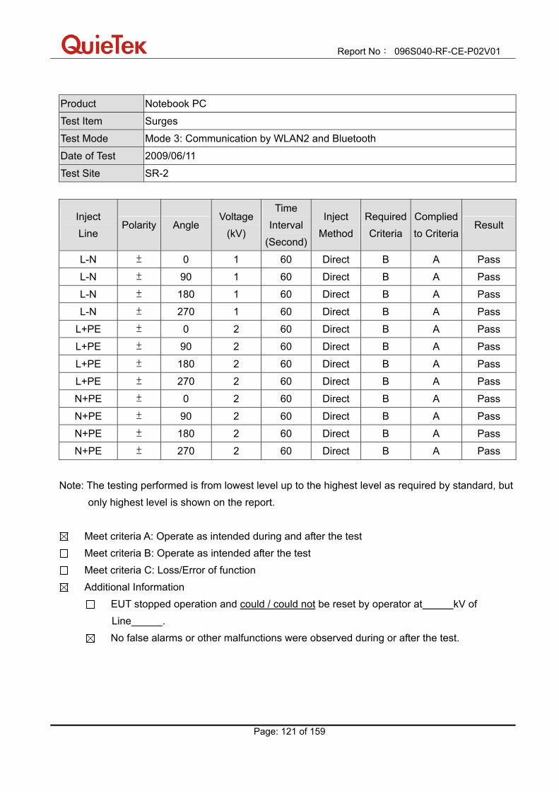
Report No: 096S040-RF-CE-P02V01
Page: 121 of 159
Product Notebook PC
Test Item Surges
Test Mode Mode 3: Communication by WLAN2 and Bluetooth
Date of Test 2009/06/11
Test Site SR-2
Inject Line
Polarity Angle Voltage
(kV)
Time Interval
(Second)
Inject Method
Required Criteria
Complied to Criteria
Result
L-N ± 0 1 60 Direct B A Pass
L-N ± 90 1 60 Direct B A Pass
L-N ± 180 1 60 Direct B A Pass
L-N ± 270 1 60 Direct B A Pass
L+PE ± 0 2 60 Direct B A Pass
L+PE ± 90 2 60 Direct B A Pass
L+PE ± 180 2 60 Direct B A Pass
L+PE ± 270 2 60 Direct B A Pass
N+PE ± 0 2 60 Direct B A Pass
N+PE ± 90 2 60 Direct B A Pass
N+PE ± 180 2 60 Direct B A Pass
N+PE ± 270 2 60 Direct B A Pass
Note: The testing performed is from lowest level up to the highest level as required by standard, but
only highest level is shown on the report.
Meet criteria A: Operate as intended during and after the test Meet criteria B: Operate as intended after the test Meet criteria C: Loss/Error of function Additional Information
EUT stopped operation and could / could not be reset by operator at kV of Line .
No false alarms or other malfunctions were observed during or after the test.

Report No: 096S040-RF-CE-P02V01
Page: 122 of 159
Product Notebook PC
Test Item Surges
Test Mode Mode 4: Standby
Date of Test 2009/06/11
Test Site SR-2
Inject Line
Polarity Angle Voltage
(kV)
Time Interval
(Second)
Inject Method
Required Criteria
Complied to Criteria
Result
L-N ± 0 1 60 Direct B A Pass
L-N ± 90 1 60 Direct B A Pass
L-N ± 180 1 60 Direct B A Pass
L-N ± 270 1 60 Direct B A Pass
L+PE ± 0 2 60 Direct B A Pass
L+PE ± 90 2 60 Direct B A Pass
L+PE ± 180 2 60 Direct B A Pass
L+PE ± 270 2 60 Direct B A Pass
N+PE ± 0 2 60 Direct B A Pass
N+PE ± 90 2 60 Direct B A Pass
N+PE ± 180 2 60 Direct B A Pass
N+PE ± 270 2 60 Direct B A Pass
Note: The testing performed is from lowest level up to the highest level as required by standard, but
only highest level is shown on the report.
Meet criteria A: Operate as intended during and after the test Meet criteria B: Operate as intended after the test Meet criteria C: Loss/Error of function Additional Information
EUT stopped operation and could / could not be reset by operator at kV of Line .
No false alarms or other malfunctions were observed during or after the test.
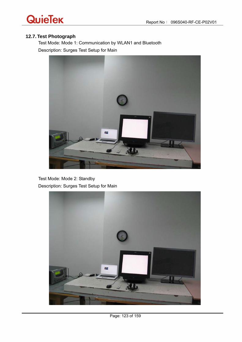
Report No: 096S040-RF-CE-P02V01
Page: 123 of 159
12.7. Test Photograph Test Mode: Mode 1: Communication by WLAN1 and Bluetooth Description: Surges Test Setup for Main
Test Mode: Mode 2: Standby Description: Surges Test Setup for Main

Report No: 096S040-RF-CE-P02V01
Page: 124 of 159
Test Mode: Mode 3: Communication by WLAN2 and Bluetooth Description: Surges Test Setup for Main
Test Mode: Mode 4: Standby Description: Surges Test Setup for Main

Report No: 096S040-RF-CE-P02V01
Page: 125 of 159
13. RF Common Mode
13.1. Test Specification According to Standard: EN 61000-4-6
13.2. Test Setup CDN Test Setup
EM Clamp Test Setup

Report No: 096S040-RF-CE-P02V01
Page: 126 of 159
13.3. Limit
Item Environmental Phenomena
Units Test Specification Performance Criteria
Signal Ports, Telecommunication Ports, Control Ports Radio-Frequency Continuous Conducted
MHz V (rms, Un-modulated) % AM (1kHz)
0.15-80 3 80
A
D.C. Power Ports Radio-Frequency Continuous Conducted
MHz V (rms, Un-modulated) % AM (1kHz)
0.15-80 3 80
A
A.C. Power Ports Radio-Frequency Continuous Conducted
MHz V (rms, Un-modulated) % AM (1kHz)
0.15-80 3 80
A
13.4. Test Procedure
The EUT are placed on a table that is 0.8 meter height, and a Ground reference plane on the table, EUT are placed upon table and use a 0.1m insulation between the EUT and Ground reference plane. For signal ports, telecommunication ports and control ports: The disturbance signal is through a coupling and decoupling networks (CDN) or EM-clamp device couples to the signal and Telecommunication lines of the EUT. For input D.C. and A.C. power ports: The EUT is connected to the power mains through a coupling and decoupling networks for power supply lines. And directly couples the disturbances signal into EUT. Used CDN-M2 for two wires or CDN-M3 for three wires.

Report No: 096S040-RF-CE-P02V01
Page: 127 of 159
All the scanning conditions are as follows: Condition of Test Remarks 1. Field Strength 3V Level 2 2. Radiated Signal AM 80% Modulated with 1kHz 3. Scanning Frequency 0.15 - 80MHz 4 Dwell Time 3 Seconds 5. Frequency step size ∆ f 1% 6. The rate of Swept of Frequency 1.5 x 10⁻³ decades/s
13.5. Deviation from Test Standard No deviation.

Report No: 096S040-RF-CE-P02V01
Page: 128 of 159
13.6. Test Result Product Notebook PC
Test Item RF Common Mode
Test Mode Mode 1: Communication by WLAN1 and Bluetooth
Date of Test 2009/06/11
Test Site SR-2
Frequency (MHz)
Voltage
(V)
Inject
Method Inject Ports
Required Criteria
Complied to Criteria
Result
0.15-80 3 CDN AC IN A A Pass
0.15-80 3 CDN LAN A A Pass
Meet criteria A: Operate as intended during and after the test Meet criteria B: Operate as intended after the test Meet criteria C: Loss/Error of function Additional Information
EUT stopped operation and could / could not be reset by operator at V, at frequency MHz.
No false alarms or other malfunctions were observed during or after the test.

Report No: 096S040-RF-CE-P02V01
Page: 129 of 159
Product Notebook PC
Test Item RF Common Mode
Test Mode Mode 2: Standby
Date of Test 2009/06/11
Test Site SR-2
Frequency (MHz)
Voltage
(V)
Inject
Method Inject Ports
Required Criteria
Complied to Criteria
Result
0.15-80 3 CDN AC IN A A Pass
0.15-80 3 CDN LAN A A Pass
Meet criteria A: Operate as intended during and after the test Meet criteria B: Operate as intended after the test Meet criteria C: Loss/Error of function Additional Information
EUT stopped operation and could / could not be reset by operator at V, at frequency MHz.
No false alarms or other malfunctions were observed during or after the test.
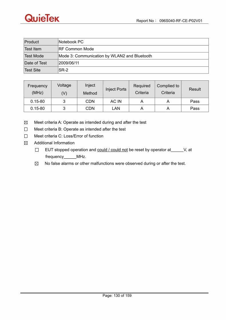
Report No: 096S040-RF-CE-P02V01
Page: 130 of 159
Product Notebook PC
Test Item RF Common Mode
Test Mode Mode 3: Communication by WLAN2 and Bluetooth
Date of Test 2009/06/11
Test Site SR-2
Frequency (MHz)
Voltage
(V)
Inject
Method Inject Ports
Required Criteria
Complied to Criteria
Result
0.15-80 3 CDN AC IN A A Pass
0.15-80 3 CDN LAN A A Pass
Meet criteria A: Operate as intended during and after the test Meet criteria B: Operate as intended after the test Meet criteria C: Loss/Error of function Additional Information
EUT stopped operation and could / could not be reset by operator at V, at frequency MHz.
No false alarms or other malfunctions were observed during or after the test.
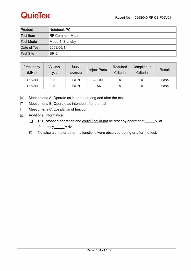
Report No: 096S040-RF-CE-P02V01
Page: 131 of 159
Product Notebook PC
Test Item RF Common Mode
Test Mode Mode 4: Standby
Date of Test 2009/06/11
Test Site SR-2
Frequency (MHz)
Voltage
(V)
Inject
Method Inject Ports
Required Criteria
Complied to Criteria
Result
0.15-80 3 CDN AC IN A A Pass
0.15-80 3 CDN LAN A A Pass
Meet criteria A: Operate as intended during and after the test Meet criteria B: Operate as intended after the test Meet criteria C: Loss/Error of function Additional Information
EUT stopped operation and could / could not be reset by operator at V, at frequency MHz.
No false alarms or other malfunctions were observed during or after the test.
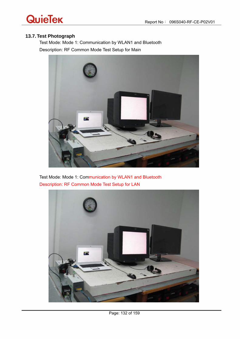
Report No: 096S040-RF-CE-P02V01
Page: 132 of 159
13.7. Test Photograph Test Mode: Mode 1: Communication by WLAN1 and Bluetooth Description: RF Common Mode Test Setup for Main
Test Mode: Mode 1: Communication by WLAN1 and Bluetooth Description: RF Common Mode Test Setup for LAN

Report No: 096S040-RF-CE-P02V01
Page: 133 of 159
Test Mode: Mode 2: Standby Description: RF Common Mode Test Setup for Main
Test Mode: Mode 2: Standby Description: RF Common Mode Test Setup for LAN

Report No: 096S040-RF-CE-P02V01
Page: 134 of 159
Test Mode: Mode 3: Communication by WLAN2 and Bluetooth Description: RF Common Mode Test Setup for Main
Test Mode: Mode 3: Communication by WLAN2 and Bluetooth Description: RF Common Mode Test Setup for LAN
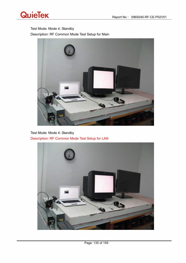
Report No: 096S040-RF-CE-P02V01
Page: 135 of 159
Test Mode: Mode 4: Standby Description: RF Common Mode Test Setup for Main
Test Mode: Mode 4: Standby Description: RF Common Mode Test Setup for LAN
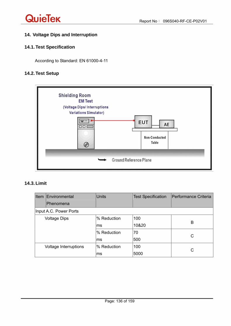
Report No: 096S040-RF-CE-P02V01
Page: 136 of 159
14. Voltage Dips and Interruption
14.1. Test Specification According to Standard: EN 61000-4-11
14.2. Test Setup
14.3. Limit Item Environmental
Phenomena Units Test Specification Performance Criteria
Input A.C. Power Ports
% Reduction ms
100 10&20
B Voltage Dips
% Reduction ms
70 500
C
Voltage Interruptions % Reduction ms
100 5000
C
Report No: 096S040-RF-CE-P02V01
Page: 137 of 159
14.4. Test Procedure The EUT and its load are placed on a table which is 0.8 meter above a metal ground plane measured 1m*1m min. And 0.65mm thick min. And projected beyond the EUT by at least 0.1m on all sides. The power cord shall be used the shortest power cord as specified by the manufacturer. For Voltage Dips/ Interruptions test: The selection of test voltage is based on the rated power range. If the operation range is large than 20% of lower power range, both end of specified voltage shall be tested. Otherwise, the typical voltage specification is selected as test voltage. The EUT is connected to the power mains through a coupling device that directly couples to the Voltage Dips and Interruption Generator. Voltage phase shifting are shall occur at 00, 450, 900, 1350, 1800, 2250, 2700, 3150 of the voltage.
14.5. Deviation from Test Standard
No deviation.
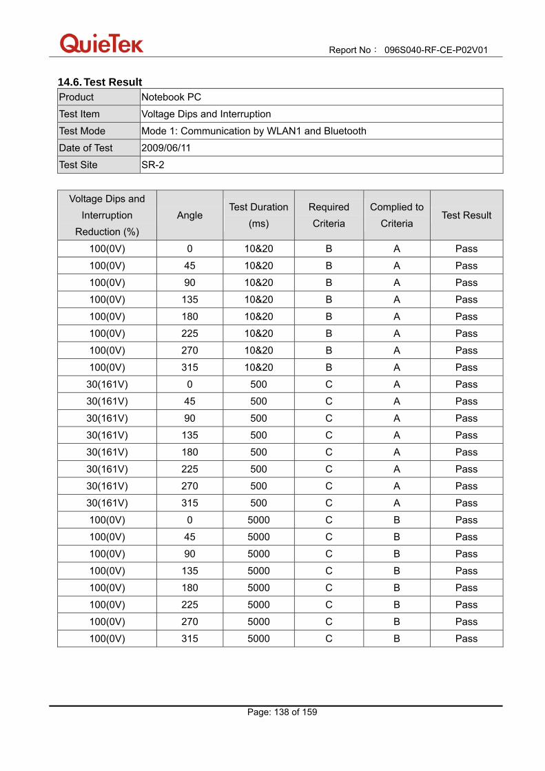
Report No: 096S040-RF-CE-P02V01
Page: 138 of 159
14.6. Test Result Product Notebook PC
Test Item Voltage Dips and Interruption
Test Mode Mode 1: Communication by WLAN1 and Bluetooth
Date of Test 2009/06/11
Test Site SR-2
Voltage Dips and
Interruption Reduction (%)
Angle Test Duration
(ms) Required Criteria
Complied to Criteria
Test Result
100(0V) 0 10&20 B A Pass
100(0V) 45 10&20 B A Pass
100(0V) 90 10&20 B A Pass
100(0V) 135 10&20 B A Pass
100(0V) 180 10&20 B A Pass
100(0V) 225 10&20 B A Pass
100(0V) 270 10&20 B A Pass
100(0V) 315 10&20 B A Pass
30(161V) 0 500 C A Pass
30(161V) 45 500 C A Pass
30(161V) 90 500 C A Pass
30(161V) 135 500 C A Pass
30(161V) 180 500 C A Pass
30(161V) 225 500 C A Pass
30(161V) 270 500 C A Pass
30(161V) 315 500 C A Pass
100(0V) 0 5000 C B Pass
100(0V) 45 5000 C B Pass
100(0V) 90 5000 C B Pass
100(0V) 135 5000 C B Pass
100(0V) 180 5000 C B Pass
100(0V) 225 5000 C B Pass
100(0V) 270 5000 C B Pass
100(0V) 315 5000 C B Pass

Report No: 096S040-RF-CE-P02V01
Page: 139 of 159
Meet criteria A: Operate as intended during and after the test Meet criteria B: Operate as intended after the test Meet criteria C: Loss/Error of function Additional Information
EUT stopped operation and could / could not be reset by operator at V, at angle.
No false alarms or other malfunctions were observed during or after the test.
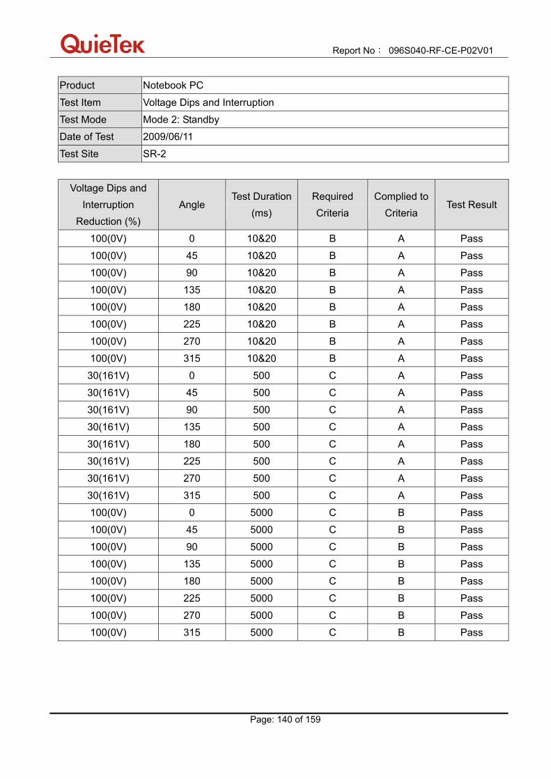
Report No: 096S040-RF-CE-P02V01
Page: 140 of 159
Product Notebook PC
Test Item Voltage Dips and Interruption
Test Mode Mode 2: Standby
Date of Test 2009/06/11
Test Site SR-2
Voltage Dips and
Interruption Reduction (%)
Angle Test Duration
(ms) Required Criteria
Complied to Criteria
Test Result
100(0V) 0 10&20 B A Pass
100(0V) 45 10&20 B A Pass
100(0V) 90 10&20 B A Pass
100(0V) 135 10&20 B A Pass
100(0V) 180 10&20 B A Pass
100(0V) 225 10&20 B A Pass
100(0V) 270 10&20 B A Pass
100(0V) 315 10&20 B A Pass
30(161V) 0 500 C A Pass
30(161V) 45 500 C A Pass
30(161V) 90 500 C A Pass
30(161V) 135 500 C A Pass
30(161V) 180 500 C A Pass
30(161V) 225 500 C A Pass
30(161V) 270 500 C A Pass
30(161V) 315 500 C A Pass
100(0V) 0 5000 C B Pass
100(0V) 45 5000 C B Pass
100(0V) 90 5000 C B Pass
100(0V) 135 5000 C B Pass
100(0V) 180 5000 C B Pass
100(0V) 225 5000 C B Pass
100(0V) 270 5000 C B Pass
100(0V) 315 5000 C B Pass

Report No: 096S040-RF-CE-P02V01
Page: 141 of 159
Meet criteria A: Operate as intended during and after the test Meet criteria B: Operate as intended after the test Meet criteria C: Loss/Error of function Additional Information
EUT stopped operation and could / could not be reset by operator at V, at angle.
No false alarms or other malfunctions were observed during or after the test.
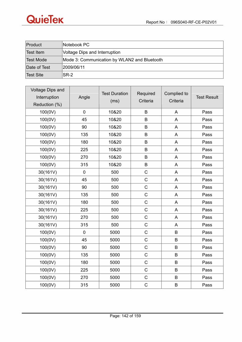
Report No: 096S040-RF-CE-P02V01
Page: 142 of 159
Product Notebook PC
Test Item Voltage Dips and Interruption
Test Mode Mode 3: Communication by WLAN2 and Bluetooth
Date of Test 2009/06/11
Test Site SR-2
Voltage Dips and
Interruption Reduction (%)
Angle Test Duration
(ms) Required Criteria
Complied to Criteria
Test Result
100(0V) 0 10&20 B A Pass
100(0V) 45 10&20 B A Pass
100(0V) 90 10&20 B A Pass
100(0V) 135 10&20 B A Pass
100(0V) 180 10&20 B A Pass
100(0V) 225 10&20 B A Pass
100(0V) 270 10&20 B A Pass
100(0V) 315 10&20 B A Pass
30(161V) 0 500 C A Pass
30(161V) 45 500 C A Pass
30(161V) 90 500 C A Pass
30(161V) 135 500 C A Pass
30(161V) 180 500 C A Pass
30(161V) 225 500 C A Pass
30(161V) 270 500 C A Pass
30(161V) 315 500 C A Pass
100(0V) 0 5000 C B Pass
100(0V) 45 5000 C B Pass
100(0V) 90 5000 C B Pass
100(0V) 135 5000 C B Pass
100(0V) 180 5000 C B Pass
100(0V) 225 5000 C B Pass
100(0V) 270 5000 C B Pass
100(0V) 315 5000 C B Pass

Report No: 096S040-RF-CE-P02V01
Page: 143 of 159
Meet criteria A: Operate as intended during and after the test Meet criteria B: Operate as intended after the test Meet criteria C: Loss/Error of function Additional Information
EUT stopped operation and could / could not be reset by operator at V, at angle.
No false alarms or other malfunctions were observed during or after the test.

Report No: 096S040-RF-CE-P02V01
Page: 144 of 159
Product Notebook PC
Test Item Voltage Dips and Interruption
Test Mode Mode 4: Standby
Date of Test 2009/06/11
Test Site SR-2
Voltage Dips and
Interruption Reduction (%)
Angle Test Duration
(ms) Required Criteria
Complied to Criteria
Test Result
100(0V) 0 10&20 B A Pass
100(0V) 45 10&20 B A Pass
100(0V) 90 10&20 B A Pass
100(0V) 135 10&20 B A Pass
100(0V) 180 10&20 B A Pass
100(0V) 225 10&20 B A Pass
100(0V) 270 10&20 B A Pass
100(0V) 315 10&20 B A Pass
30(161V) 0 500 C A Pass
30(161V) 45 500 C A Pass
30(161V) 90 500 C A Pass
30(161V) 135 500 C A Pass
30(161V) 180 500 C A Pass
30(161V) 225 500 C A Pass
30(161V) 270 500 C A Pass
30(161V) 315 500 C A Pass
100(0V) 0 5000 C B Pass
100(0V) 45 5000 C B Pass
100(0V) 90 5000 C B Pass
100(0V) 135 5000 C B Pass
100(0V) 180 5000 C B Pass
100(0V) 225 5000 C B Pass
100(0V) 270 5000 C B Pass
100(0V) 315 5000 C B Pass
Report No: 096S040-RF-CE-P02V01
Page: 145 of 159
Meet criteria A: Operate as intended during and after the test Meet criteria B: Operate as intended after the test Meet criteria C: Loss/Error of function Additional Information
EUT stopped operation and could / could not be reset by operator at V, at angle.
No false alarms or other malfunctions were observed during or after the test.

Report No: 096S040-RF-CE-P02V01
Page: 146 of 159
14.7. Test Photograph Test Mode : Mode 1: Communication by WLAN1 and Bluetooth Description : Voltage Dips and Interruption Test Setup
Test Mode : Mode 2: Standby Description : Voltage Dips and Interruption Test Setup
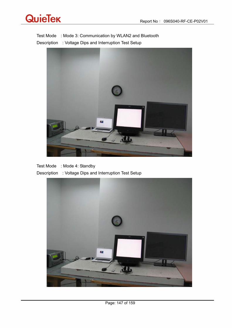
Report No: 096S040-RF-CE-P02V01
Page: 147 of 159
Test Mode : Mode 3: Communication by WLAN2 and Bluetooth Description : Voltage Dips and Interruption Test Setup
Test Mode : Mode 4: Standby Description : Voltage Dips and Interruption Test Setup

Report No: 096S040-RF-CE-P02V01
Page: 148 of 159
15. Transients and surges
15.1. Test Specification According to Standard: ISO 7637-2
15.2. Test Setup
15.3. Limit EUT applying pulses 1, 2a, 2b, 3a, 3b, and 4, using immunity test level Ⅲ. For the purpose of EMC testing it is sufficient to apply pulses 1, 2a and 4, 10 times each, and apply the test pulses 3a and 3b for 20 minutes each.
15.4. Test Procedure Test requirements for 12 V DC powered equipment: Where the manufacturer in his installation documentation requires the radio equipment to have a direct connection to the 12 V main vehicle battery the requirements in a) shall apply. Where the manufacturer does not require the radio equipment to have a direct connection to the 12 V main vehicle battery the requirements in a) and b) shall apply: Pulse 3a and 3b, level II, with the test time reduced to 5 min for each; Pulse 4, level II, 5 pulses, with the characteristics as follows: Vs = -5 V; Va = -2.5 V; t6 = 25 ms; t7 = 50 ms; t8 = 5 s; tf = 5 ms; pulse cycle time: 60 s Pulse, level II: t1 = 2.5 s; 10 pulses; Pulse 2, level II: t1 = 2.5 s; 10 pulses;

Report No: 096S040-RF-CE-P02V01
Page: 149 of 159
Pulse 7, 5 pulses. Where the manufacturer declares that the radio equipment requires a direct connection to the main vehicle battery, and therefore the tests in accordance with the requirements b) are not carried out, this shall be stated in the test report. Test requirements for 24 V DC powered equipment: Where the manufacturer in his installation documentation requires the radio equipment to have a direct connection to the 24 V main vehicle battery the requirements in c) shall apply. Where the manufacturer does not require the radio equipment to have a direct connection to the 24 V main vehicle battery the requirements in c) and d) shall apply: c) Pulse 3a and 3b, level II, with the test time reduced to 5 min for each; Pulse 4, level II, 5 pulses, with the characteristics as follows: Vs = -10 V; Va = -5 V; t6 = 25 ms; t7 = 50 ms; t8 = 5 s; tf = 10 ms; pulse cycle time: 60 s d) Pulse 1a, level II: t1 = 2.5 s; Ri = 25 Ω; 10 pulses; Pulse 2b, level II: t1 = 2.5 s; Ri = 100 Ω; 10 pulses; Pulse 2, 10 pulses. Where the manufacturer declares that the radio equipment requires a direct connection to the main vehicle battery, and therefore the tests in accordance with the requirements d) are not carried out, this shall be stated in the test report. Radio and ancillary equipment designed to operate at both DC power voltages shall be tested in both configurations.
15.5. Deviation from Test Standard No deviation.
15.6. Test Result The EUT is not used for vehicular, so the test item is not necessary performed.

Report No: 096S040-RF-CE-P02V01
Page: 150 of 159
16. Attachment EUT Photograph
(1) EUT Photo
(2) EUT Photo

Report No: 096S040-RF-CE-P02V01
Page: 151 of 159
(3) EUT Photo
(4) EUT Photo
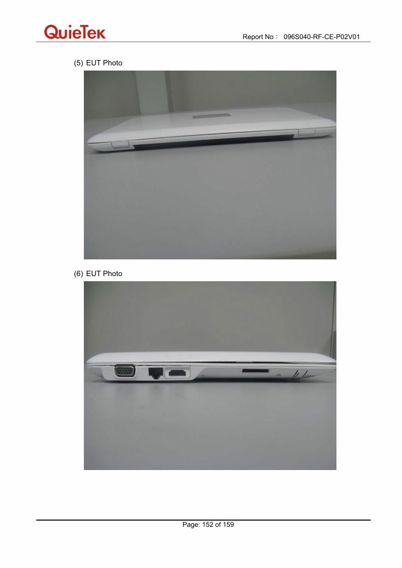
Report No: 096S040-RF-CE-P02V01
Page: 152 of 159
(5) EUT Photo
(6) EUT Photo

Report No: 096S040-RF-CE-P02V01
Page: 153 of 159
(7) EUT Photo
(8) EUT Photo

Report No: 096S040-RF-CE-P02V01
Page: 154 of 159
(9) EUT Photo
(10) EUT Photo

Report No: 096S040-RF-CE-P02V01
Page: 155 of 159
(11) EUT Photo
(12) EUT Photo

Report No: 096S040-RF-CE-P02V01
Page: 156 of 159
(13) EUT Photo
(14) EUT Photo

Report No: 096S040-RF-CE-P02V01
Page: 157 of 159
(15) EUT Photo
(16) EUT Photo

Report No: 096S040-RF-CE-P02V01
Page: 158 of 159
(17) EUT Photo
(18) EUT Photo
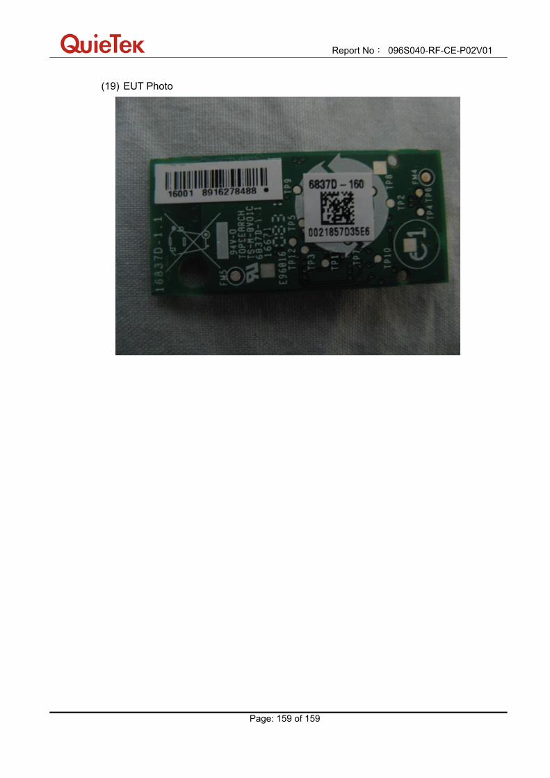
Report No: 096S040-RF-CE-P02V01
Page: 159 of 159
(19) EUT Photo


![[CZE] - PCWord Edition - MS Excel a Pr-ce Se Vzorci](https://img.pdfslide.tips/doc/110x75/543fc75dafaf9ff3098b4b1c/cze-pcword-edition-ms-excel-a-pr-ce-se-vzorci.jpg)