Embed Size (px)
Citation preview

1
CEENBot
Chassis Assembly
GENERAL: While operating, the CEENBot stepper motors will cause some vibration. The hardware must
be securely tightened to prevent parts from vibrating loose and to ensure quiet operation.
Recommended tools are:
#1 Phillips screwdriver for 4-40 screws.
#2 Phillips screwdriver for 6-32 screws.
¼” socket or nut driver for the 4-40 nuts.
5/16” socket or nut driver for the 6-32 nuts.
11/32” socket or nut driver for the 8-32 nuts.
½” socket or nut driver for the wheel nuts.
7/16” socket or nut driver for the kingpin assembly.
Pliers
Ruler
Screw and Nut Descriptors
The screws and nuts are specified by their diameter, the number of threads per inch, and the length of
the screw. The two diameters of screws and nuts are #4 and #6. The #4 is smaller than the #6. The #4
screws have 40 threads per inch and the #6 screws have 32 threads per inch. The designation 4-40 x ½”
means a #4 screw with 40 threads per inch that is ½” long.
Most of the nuts used have a nylon insert which prevents them from loosening from vibrations. You will
need a nut driver or pliers to hold the nut when tightening it. This type nut is called a nylon lock nut in
this document.
Standoff
A standoff is a spacer used to provide adequate space between circuit boards. A standoff is specified by
its length and the type of threads it has. It could have tapped holes (female) on one or both ends or it
could have male threads on one or both ends. Those with female threads on both ends are listed as
Female – Female (F – F) and those with one female and one male end are listed as Female – Male (F –
M)
2
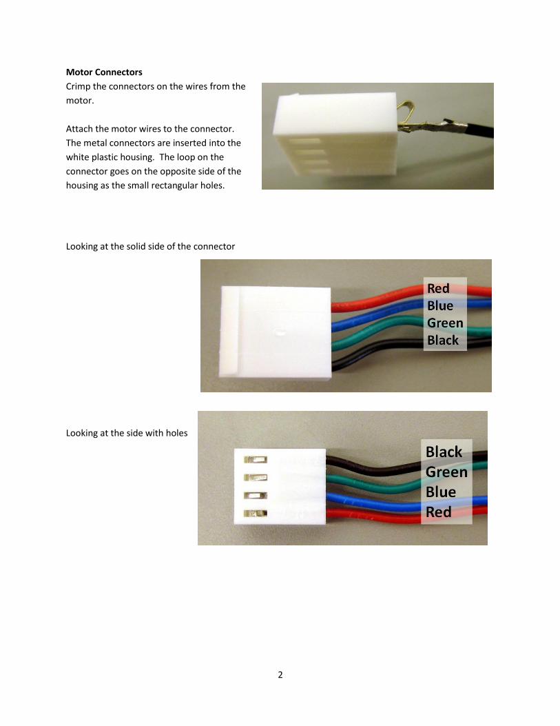
Motor Connectors
Crimp the connectors on the wires from the
motor.
Attach the motor wires to the connector.
The metal connectors are inserted into the
white plastic housing. The loop on the
connector goes on the opposite side of the
housing as the small rectangular holes.
Looking at the solid side of the connector
Looking at the side with holes

3
Shock Towers: Mount the shock towers to the sway bars as shown. The view is from the front of the
CEENBot. The half-moon cut-outs of the sway bars are to the top. The right shock tower (on the left
side of the photo) is mounted by screwing two 6x32x1/4” screws into the threaded sway bar. The left
shock tower (on the right side of the photo) is placed on the inside of the sway bar and mounted by
screwing the 6x32x1/4” screws into the threaded shock tower. These parts will only go together one
way. They are not interchangeable left to right, top to bottom or front to back. Many people think they
have defective or wrong parts when they really are putting them in the wrong place. Pay particular
attention to the location of the holes and whether they are tapped (threaded) or just drilled.
Mount the 3/8” angle aluminum to the tops of the shock towers using 4x40x3/8” screws and nylon lock
nuts.

4
Motor
Mount the motors to the sway arms using the 4-40 x 5/16”
screws and split lock washers. The lock washers go
between the screw head and the sway arm.
Stabilizers:
Press the
Metal inserts
into the end
hole of the
plastic ends.
Use a nut
driver over the
plastic to
apply even
pressure on
the plastic or
use a pair of
pliers to force the insert.
Thread the stabilizer bar ends onto the 4x40
allthread. Screw both ends until 1 1/8”
allthread remains visible. You may need to cut
about ¼” from the allthread to get this
distance. The lab instructor has a cutting tool to do this.
5
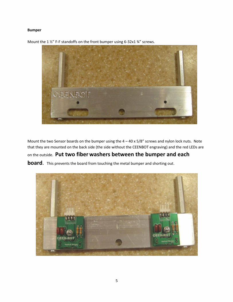
Bumper
Mount the 1 ½” F-F standoffs on the front bumper using 6-32x1 ¾” screws.
Mount the two Sensor boards on the bumper using the 4 – 40 x 5/8” screws and nylon lock nuts. Note
that they are mounted on the back side (the side without the CEENBOT engraving) and the red LEDs are
on the outside. Put two fiber washers between the bumper and each
board. This prevents the board from touching the metal bumper and shorting out.
6
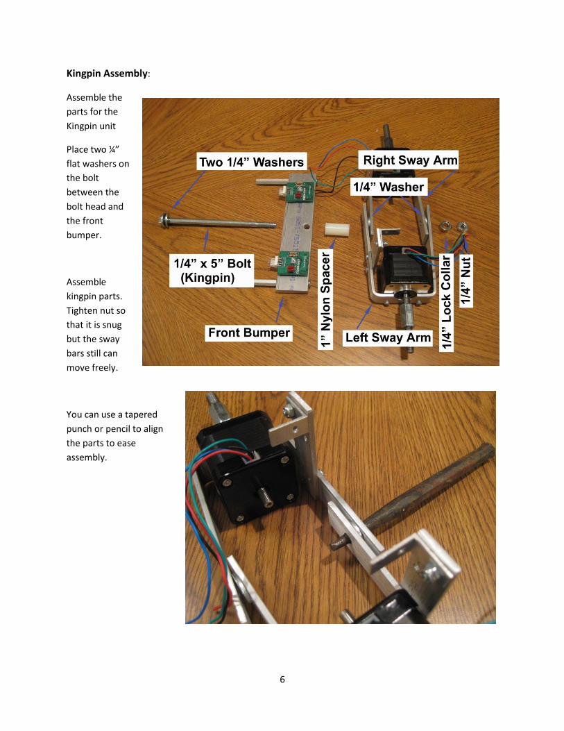
Kingpin Assembly:
Assemble the
parts for the
Kingpin unit
Place two ¼”
flat washers on
the bolt
between the
bolt head and
the front
bumper.
Assemble
kingpin parts.
Tighten nut so
that it is snug
but the sway
bars still can
move freely.
You can use a tapered
punch or pencil to align
the parts to ease
assembly.

7
Place standoffs on aluminum tray as shown in the photograph. Use 6 – 32 x 1/2” screws. The rear 1 ½”
F-F standoffs will have 1 ¼” M – F standoffs screwed into them.
Attach the stabilizers to the tray as shown using 4x40x1/2” screws and locking nylon nuts.
8
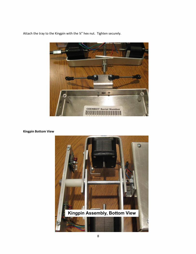
Attach the tray to the Kingpin with the ¼” hex nut. Tighten securely.
Kingpin Bottom View
9
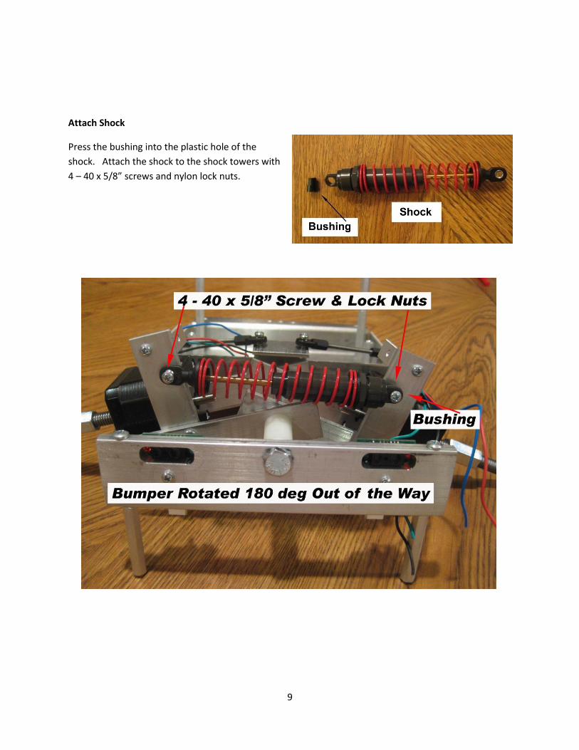
Attach Shock
Press the bushing into the plastic hole of the
shock. Attach the shock to the shock towers with
4 – 40 x 5/8” screws and nylon lock nuts.

10
Mount Stabilizer
Attack the end of each stabilizer to its bracket on the shock tower. Use 4 – 40 x ½” screws and nylon
lock nuts.
Insert Shims on shock
There are a variety of shims which can be placed on the barrel of the shock to adjust the stiffness of the
suspension. Compress the spring and insert one of the larger shims over the barrel of the shock. There
is a plastic collar that the spring presses against. Shim goes between this collar and the plastic end of
the shock. Keep the remaining shims for future modifications of the suspension.
11
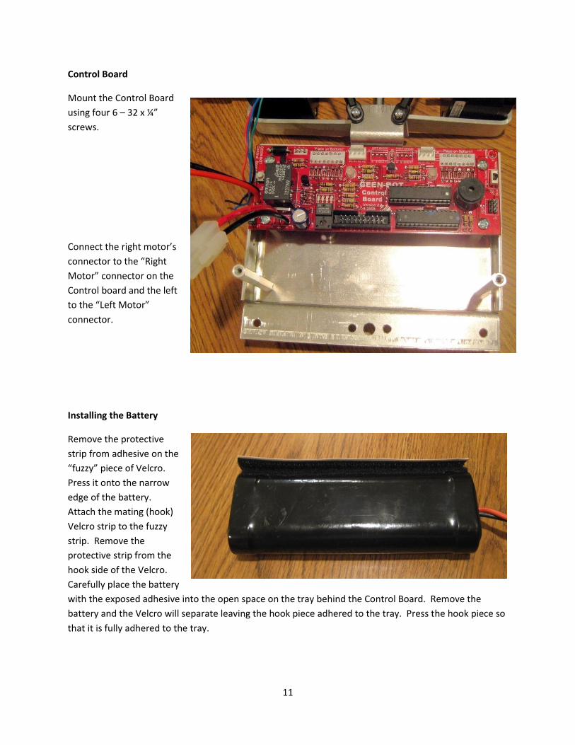
Control Board
Mount the Control Board
using four 6 – 32 x ¼”
screws.
Connect the right motor’s
connector to the “Right
Motor” connector on the
Control board and the left
to the “Left Motor”
connector.
Installing the Battery
Remove the protective
strip from adhesive on the
“fuzzy” piece of Velcro.
Press it onto the narrow
edge of the battery.
Attach the mating (hook)
Velcro strip to the fuzzy
strip. Remove the
protective strip from the
hook side of the Velcro.
Carefully place the battery
with the exposed adhesive into the open space on the tray behind the Control Board. Remove the
battery and the Velcro will separate leaving the hook piece adhered to the tray. Press the hook piece so
that it is fully adhered to the tray.
12
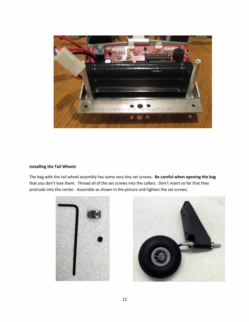
Installing the Tail Wheels
The bag with the tail wheel assembly has some very tiny set screws. Be careful when opening the bag
that you don’t lose them. Thread all of the set screws into the collars. Don’t insert so far that they
protrude into the center. Assemble as shown in the picture and tighten the set screws.

13
Mount the tail wheels to the tail ledge
with 6 – 32 x 1/2” screws and nylon lock
nuts. Install with the lock nuts on the top.
The photo shows them backwards. The
larger surface area against the plastic
provides more strength and the plastic
bracket is not as likely to break on hard
landings.
Drive Wheels
Tire Assembly: Place the foam which came with the tires in the center of the tire and arrange such that
there is a hole in the center.
14
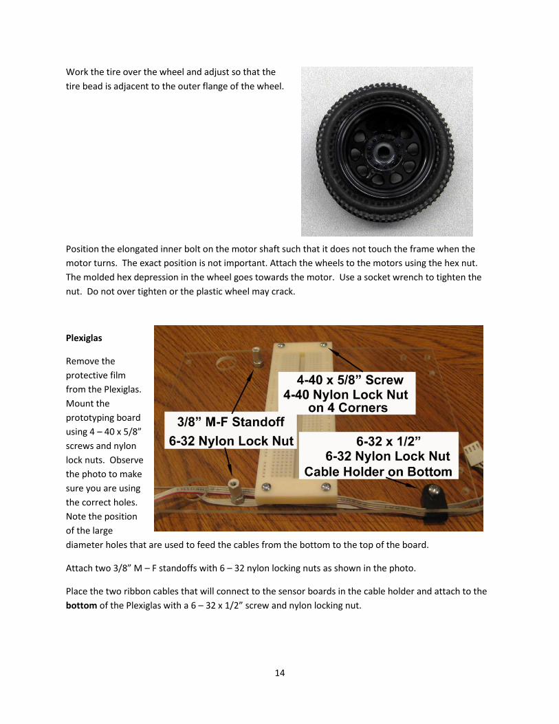
Work the tire over the wheel and adjust so that the
tire bead is adjacent to the outer flange of the wheel.
Position the elongated inner bolt on the motor shaft such that it does not touch the frame when the
motor turns. The exact position is not important. Attach the wheels to the motors using the hex nut.
The molded hex depression in the wheel goes towards the motor. Use a socket wrench to tighten the
nut. Do not over tighten or the plastic wheel may crack.
Plexiglas
Remove the
protective film
from the Plexiglas.
Mount the
prototyping board
using 4 – 40 x 5/8”
screws and nylon
lock nuts. Observe
the photo to make
sure you are using
the correct holes.
Note the position
of the large
diameter holes that are used to feed the cables from the bottom to the top of the board.
Attach two 3/8” M – F standoffs with 6 – 32 nylon locking nuts as shown in the photo.
Place the two ribbon cables that will connect to the sensor boards in the cable holder and attach to the
bottom of the Plexiglas with a 6 – 32 x 1/2” screw and nylon locking nut.
15
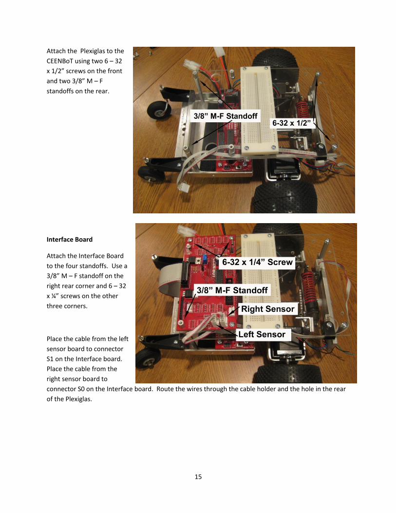
Attach the Plexiglas to the
CEENBoT using two 6 – 32
x 1/2” screws on the front
and two 3/8” M – F
standoffs on the rear.
Interface Board
Attach the Interface Board
to the four standoffs. Use a
3/8” M – F standoff on the
right rear corner and 6 – 32
x ¼” screws on the other
three corners.
Place the cable from the left
sensor board to connector
S1 on the Interface board.
Place the cable from the
right sensor board to
connector S0 on the Interface board. Route the wires through the cable holder and the hole in the rear
of the Plexiglas.
16
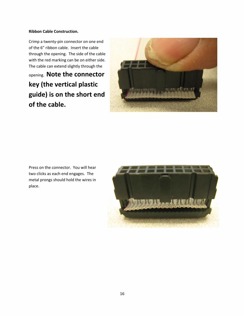
Ribbon Cable Construction.
Crimp a twenty-pin connector on one end
of the 6” ribbon cable. Insert the cable
through the opening. The side of the cable
with the red marking can be on either side.
The cable can extend slightly through the
opening. Note the connector
key (the vertical plastic
guide) is on the short end
of the cable.
Press on the connector. You will hear
two clicks as each end engages. The
metal prongs should hold the wires in
place.

17
Use pliers to force the connector together. The type of pliers shown works well because they can exert
fairly even pressure on the surface. Needle nose pliers usually do not work well.
Move the pliers to the other end to keep the connector parts parallel.
When completed, the plastic of the top part
should be against the plastic of the other
part.
Before attaching the second connector to the other end
STOP and LOOK.
The plastic key goes to the stub end. The female sockets of one connector will point up and the
other will point down.
18
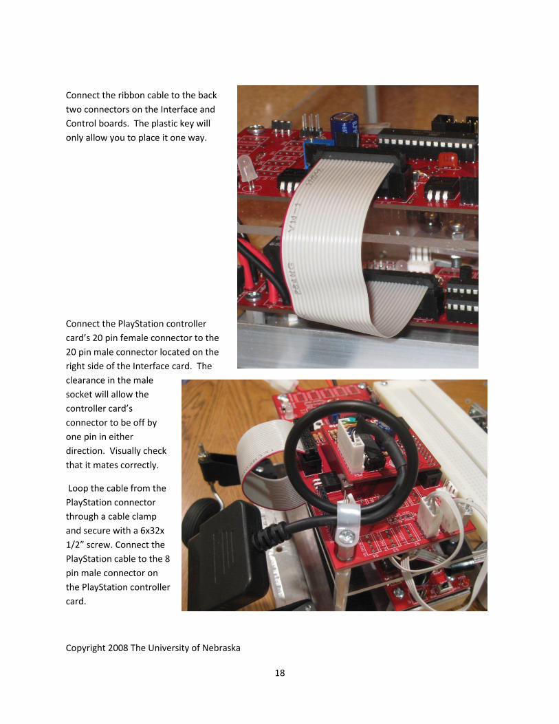
Connect the ribbon cable to the back
two connectors on the Interface and
Control boards. The plastic key will
only allow you to place it one way.
Connect the PlayStation controller
card’s 20 pin female connector to the
20 pin male connector located on the
right side of the Interface card. The
clearance in the male
socket will allow the
controller card’s
connector to be off by
one pin in either
direction. Visually check
that it mates correctly.
Loop the cable from the
PlayStation connector
through a cable clamp
and secure with a 6x32x
1/2” screw. Connect the
PlayStation cable to the 8
pin male connector on
the PlayStation controller
card.
Copyright 2008 The University of Nebraska