Embed Size (px)
Citation preview
- 35 - EFDA Technology / Vessel-In Vessel / Vessel-Blanket and Materials
CEFDA03-1067 Task Title: TW3-TVM-MDB: RULES FOR DESIGN, FABRICATION AND
INSPECTION Establishment and maintenance of a materials database
INTRODUCTION Material research represents a significant part of the European and World-wide efforts on Fusion research. The properties of new and existing materials need to be known in detail by Designers, by Licensing Authorities and not the least by Material Scientists. The present requirement for a materials Database comes firstly from a need by ITER to establish the status of Fusion materials data for licensing purposes and secondly to consolidate the data so that it is easily available to material researchers in the future, to identify holes in our existing knowledge base and to help establish directions for future material research. The data that are subject of this proposal are those that have been measured and collected as part of the European Fusion program in support of NET and ITER over the past two decades. The database constructed shall in the first instance, concentrate on the mechanical properties and thermal properties of both structural and plasma facing materials collected as part of the Next Step activities. For this purpose UKAEA has been granted a contract as lead association with CEA and HAS as supporting associations. The final task report is expected to describe the following aspects of the work done : - A description of the database and its structure.
- A list of procedures generated during the database activity.
- A list of users of the database.
- A list of contributors to the database and their contribution.
- A list of reports referred to by the database. As supporting association, CEA will advise the lead association, UKAEA, throughout the project on the following issues: - The definition of the detailed database structure and
format of the information.
- The collection of data.
- Checking of data.
- Maintenance of database.
- Installation, running of database and development of criteria to access and use the database.
2003 ACTIVITIES Two meetings were held in 2003 where the progress of work was examined. CEA has provided EFDA with an assessment report. In this report it is stated that the progress of the work done so far has been promising. The intention of putting in place a flexible database server with free access to all participating institutes, and the possibility of maintaining the database independent of a particular software is well appreciated. However, the work to be done is still in its very early stages. It is suggested to proceed in step-by-step approach. Starting with a simple working solution for a well established database, such as the 316LN steel, and gradually expanding to materials for which the information is still sparse and evolving. Given the variety of materials used in ITER and the diversity of the materials properties to be stored, the database structure should be flexible and capable of easily integrating new features, new properties, new fields, etc.
400
500
600
700
800
900
1000
1100
1200
0 200 400 600 800 1000
Specific Heat (J/kg.K)
Temperature, ∞C
F82H
9Cr-1MO
Eurofer (Heat E83699)
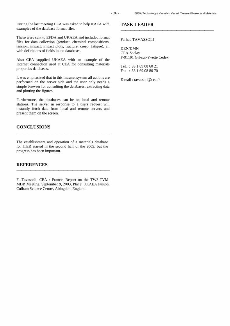
Figure 1 : Comparison of the specific heat values of the Eurofer steel with those of the conventional
9Cr-1Mo steel and the reduced activation F82H steel Finally, the work on collecting materials properties data, harmonizing, and validating them should be the essential part of this task.
- 36 - EFDA Technology / Vessel-In Vessel / Vessel-Blanket and Materials
During the last meeting CEA was asked to help KAEA with examples of the database format files. These were sent to EFDA and UKAEA and included format files for data collection (product, chemical compositions, tension, impact, impact plots, fracture, creep, fatigue), all with definitions of fields in the databases. Also CEA supplied UKAEA with an example of the Internet connection used at CEA for consulting materials properties databases. It was emphasized that in this Intranet system all actions are performed on the server side and the user only needs a simple browser for consulting the databases, extracting data and plotting the figures. Furthermore, the databases can be on local and remote stations. The server in response to a users request will instantly fetch data from local and remote servers and present them on the screen. CONCLUSIONS The establishment and operation of a materials database for ITER started in the second half of the 2003, but the progress has been important. REFERENCES F. Tavassoli, CEA / France, Report on the TW3-TVM-MDB Meeting, September 9, 2003, Place: UKAEA Fusion, Culham Science Centre, Abingdon, England.
TASK LEADER Farhad TAVASSOLI DEN/DMN CEA-Saclay F-91191 Gif-sur-Yvette Cedex Tél. : 33 1 69 08 60 21 Fax : 33 1 69 08 80 70 E-mail : [email protected]

Not available on line

Not available on line

Not available on line

Not available on line

Not available on line

Not available on line

Not available on line

Not available on line

Not available on line

Not available on line

Not available on line

Not available on line

Not available on line

Not available on line

Not available on line

Not available on line

Not available on line

Not available on line

Not available on line

Not available on line

Not available on line

Not available on line

Not available on line

Not available on line
- 61 - EFDA Technology / Vessel-In Vessel / Vessel-Blanket and Materials
TW3-TVV-UTDYNAM Task Title: DEVELOPMENT OF DYNAMIC PHASED ARRAY TECHNIQUES INTRODUCTION The aim of the study is to develop a non destructive testing process to inspect the inner-sector welds during the assembly of the vacuum vessel of ITER. In 2001, studies in the framework of EFDA contract 00-556 and an EFET work allowed to investigate various UT techniques relevant for detection of defects all along the welded component, both by simulation and experiment, and to design specific phased array probes which were able to perform most of these techniques with improved performances in terms of adaptability. In 2002 EFDA task TW2-TVV-UTINSP (“Further development of ultrasonic inspection process”), phased array probes have been used by CEA in order to apply different UT techniques to detect defects located all along the thickness of an EB weld and a TIG weld. The present task is an extension of the 2002 task, in order to ensure the integrity of the component, which requires to solve the following items: 1- Dynamic mode inspections based on tandem techniques
are very efficient for defect detection (high signal-to-noise ratio), but they cannot be used for accurate defect sizing. Techniques relying on the detection of diffraction echoes, as Time Of Flight Diffraction (TOFD) technique or beam-steering, would be very efficient for accurate defect sizing, but diffraction echoes may be low compared to the structural noise of the weld.
2- The geometry of the component may be slightly
different from the planar specimen which has been considered for previous experiments and simulations studies.
2003 ACTIVITIES Experimental trials have been performed at CEA to evaluate the phased array techniques ability to size defects in the EB-weld and the TIG-weld. Experiments have been carried out using phased array probes defined and manufactured in the framework of the TW2-TVV-UTINSP program. Other probes have been defined and manufactured in 2003 to optimise the detection and sizing performances and to take into account the restricted access to the weld. Beam-steering techniques have been applied over the EB weld. This inspection technique relies on a fixed phased array probe which is used to sweep the beam between 0° to 80° thanks to successive delay laws.
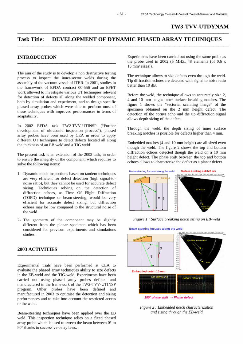
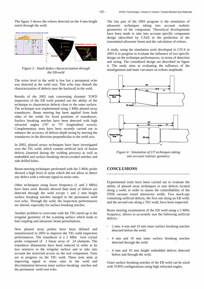
Experiments have been carried out using the same probe as the probe used in 2002 (5 MHZ, 48 elements (of 0.6 x 15 mm² sizes)). The technique allows to size defects even through the weld. Tip diffraction echoes are detected with signal to noise ratio better than 10 dB. Before the weld, the technique allows to accurately size 2, 4 and 10 mm height inner surface breaking notches. The figure 1 shows the “sectorial scanning image” of the specimen obtained on the 2 mm height defect. The detection of the corner echo and the tip diffraction signal allows depth sizing of the defect. Through the weld, the depth sizing of inner surface breaking notches is possible for defects higher than 4 mm. Embedded notches (4 and 10 mm height) are all sized even though the weld. The figure 2 shows the top and bottom diffraction echoes detected though the weld on a 10 mm height defect. The phase shift between the top and bottom echoes allows to characterize the defect as a planar defect.
idiffraction
Corner echo on notch
6058
L
EBEB WeldWeld
Surface breaking notch 2 mmBeam-steering focused along the weld
Figure 1 : Surface breaking notch sizing on EB-weld
60
35
Tip diffraction on notch
Embedded notch 10 mm
weld
Beam-steering focused along the weld
180° phase shift ⇒ Planar defect
Top diffraction Bottom diffraction
Figure 2 : Embedded notch characterization and sizing through the EB-weld
- 62 - EFDA Technology / Vessel-In Vessel / Vessel-Blanket and Materials
The figure 3 shows the echoes detected on the 4 mm height notch through the weld.
SDH 15mm
SDH 30mm
N4 mm
Backwall
60
3052
56
15
Tip diffraction on notch
Embedded notch 4 mm
Corner echo on notch
weld
Beam-steering focused along the weld
Figure 3 : Small dedect characterization through the EB-weld
The noise level in the weld is low but a permanent echo was detected at the weld root. This echo may disturb the characterization of defects near the backwall in the weld. Results of the 2002 task concerning dynamic TOFD inspection of the EB weld pointed out the ability of the technique to characterize defects close to the outer surface. The technique was implemented using 5 MHz phased array transducers. Beam steering has been applied from both sides of the welds for fixed positions of transducers. Surface breaking notches have been detected with high refracted angles (70° to 75° longitudinal waves). Complementary tests have been recently carried out to enhance the accuracy of defects depth sizing by moving the transducers in the direction perpendicular to the weld axis. In 2002, phased arrays techniques have been investigated over the TIG weld, which contain artificial lack of fusion defects (inserted during the welding process) as well as embedded and surface breaking electro-eroded notches and side drilled holes. Beam-steering techniques performed with the 5 MHz probe showed a high level of noise which did not allow to detect any defect with a relevant signal-to-noise ratio. Other techniques using lower frequency (1 and 2 MHz) have been used. Results showed than most of defects are detected through the weld except 1 and 2 mm height surface breaking notches merged in the permanent weld root echo. Through the weld, the inspection performances are altered, especially for surface breaking notches. Another problem to overcome with the TIG mock-up is the irregular geometry of the scanning surface which leads to bad coupling and ultrasonic beam perturbations. New phased array probes have been defined and manufactured in 2003 to improve the TIG weld inspection performances. The transducer is a 2 MHz twin crystal probe composed of 2 linear array of 24 elements. The transducer dimensions have been reduced in order to be less sensitive to the irregular surface and to take into account the restricted access on the real component. Tests are in progress on the TIG weld. These tests aims at improving signal to noise ratio in the weld and discrimination between inner surface breaking notches and the permanent weld root echo.
The last part of the 2003 program is the simulation of ultrasonic techniques taking into account realistic geometries of the component. Theoretical developments have been made to take into account specific component design (described by CAD) in the prediction of the transmitted ultrasonic beam and the calculation of echoes. A study, using the simulation tools developed in CIVA in 2003 is in progress to evaluate the influence of two specific design on the technique performances, in terms of detection and sizing. The considered design are described on figure 4. The study aims at evaluating the influence of the misalignment and inner curvature on echoes amplitude.
120
260
60
70
1 1’
Vacuum VesselShell
10 mm
120
260
60
70
1 1’
Vacuum VesselShell
10 mm
120
260
60
70
1 1’
Vacuum VesselShell
10 mm
120
260
60
70
1 1’
Vacuum VesselShell
10 mm
120
260
60
70
11’
Vacuum VesselShell 80 mm
120
260
60
70
11’
Vacuum VesselShell 80 mm
120
260
60
70
11’
Vacuum VesselShell 80 mm
120
260
60
70
11’
Vacuum VesselShell 80 mm
Figure 4 : Simulation of UT techniques taking into account realistic geometry
CONCLUSIONS Experimental trials have been carried out to evaluate the ability of phased array techniques to size defects located along a weld, in order to assess the controllability of the ITER vacuum vessel intersector welds. Two mock-ups containing artificial defects, the first one along an EB weld, and the second one along a TIG weld, have been inspected. Beam steering examination of the EB weld using a 5 MHz frequency, allows to accurately size the following artificial defects : - 2 mm, 4 mm and 10 mm inner surface breaking notches
detected before the weld. - 4 mm and 10 mm inner surface breaking notches
detected through the weld. - 4 mm and 10 mm height embedded defects detected
before and through the weld. Outer surface breaking notches of the EB weld can be sized with TOFD configurations using high refracted angles.
- 63 - EFDA Technology / Vessel-In Vessel / Vessel-Blanket and Materials
New phased array probes have been defined and manufactured to improve detection and sizing performances on the TIG weld. The method implemented with these new transducers may improve the inspection performances. Ultrasonic techniques are simulated taking into account realistic geometry in order to evaluate the influence of the geometry on the detection and sizing performances. REPORTS AND PUBLICATIONS [1] Development of ultrasonic non destructive testing
method for the vessel inter-sector weld of ITER : simulation of welding process, DECS/SISC/LMUS/ 02-RT0052, July 2002.
[2] Development of ultrasonic non destructive testing
method for the vessel inter-sector weld of ITER : development of dynamic phased array techniques, SISC/03 RT0096/Rev.0, September 2003.
TASK LEADER Philippe BREDIF DRT/DETECS/SYSSC/LMUS CEA-Saclay F-91191Gif-sur-Yvette Cedex Tél. : 33 1 69 08 34.68 Fax : 33 1 69 08 75 97 E-mail : [email protected]