Embed Size (px)
Citation preview
认证之家 http://www.ait0769.com
EUROPEAN STANDARD EN 55022
NORME EUROPÉENNE
EUROPÄISCHE NORM September 2006
CENELEC European Committee for Electrotechnical Standardization
Comité Européen de Normalisation Electrotechnique Europäisches Komitee für Elektrotechnische Normung
Central Secretariat: rue de Stassart 35, B - 1050 Brussels
© 2006 CENELEC - All rights of exploitation in any form and by any means reserved worldwide for CENELEC members.
Ref. No. EN 55022:2006 E
ICS 33.100.10 Supersedes EN 55022:1998 + A1:2000 + A2:2003
English version
Information technology equipment - Radio disturbance characteristics -
Limits and methods of measurement (CISPR 22:2005, modified)
Appareils de traitement de l'information - Caractéristiques des perturbations radioélectriques - Limites et méthodes de mesure (CISPR 22:2005, modifiée)
Einrichtungen der Informationstechnik - Funkstöreigenschaften - Grenzwerte und Messverfahren (CISPR 22:2005, modifiziert)
This European Standard was approved by CENELEC on 2005-09-13. CENELEC members are bound to comply with the CEN/CENELEC Internal Regulations which stipulate the conditions for giving this European Standard the status of a national standard without any alteration. Up-to-date lists and bibliographical references concerning such national standards may be obtained on application to the Central Secretariat or to any CENELEC member. This European Standard exists in three official versions (English, French, German). A version in any other language made by translation under the responsibility of a CENELEC member into its own language and notified to the Central Secretariat has the same status as the official versions. CENELEC members are the national electrotechnical committees of Austria, Belgium, Cyprus, the Czech Republic, Denmark, Estonia, Finland, France, Germany, Greece, Hungary, Iceland, Ireland, Italy, Latvia, Lithuania, Luxembourg, Malta, the Netherlands, Norway, Poland, Portugal, Romania, Slovakia, Slovenia, Spain, Sweden, Switzerland and the United Kingdom.
EN 55022:2006 – 2 –
Foreword
The text of the International Standard CISPR 22:2003 as well as A1:2004 and CISPR/I/136/FDIS (Amendment 3) and CISPR/I/128/CDV (Amendment 2, fragment 17), prepared by CISPR SC I "Electromagnetic compatibility of information technology equipment, multimedia equipment and receivers", together with the common modifications prepared by the Technical Committee CENELEC TC 210, Electromagnetic compatibility (EMC), was submitted to the CENELEC Unique Acceptance Procedure for acceptance as a European Standard.
In addition, the text of CISPR/I/135A/FDIS (future A2, fragment 1) to CISPR 22:2003, also prepared by CISPR SC I "Electromagnetic compatibility of information technology equipment, multimedia equipment and receivers", was submitted to the CENELEC formal vote as prAD to prEN 55022:2005, with the intention of the two documents being merged and ratified together as a new edition of EN 55022.
During the period of voting on these CENELEC drafts, the amendments CISPR/I/135A/FDIS and CISPR/I/136/FDIS (Amendments 2 and 3 respectively) made to CISPR 22:2003, resulted in the publication of a new (fifth) edition of CISPR 22, in accordance with IEC rules. The resulting CISPR 22:2005 was published in April 2005.
This resulting version of EN 55022, which was ratified on 2005-09-13, is therefore identical to CISPR 22:2005 except for the common modifications that were included in the document submitted to the CENELEC Unique Acceptance Procedure. The common modifications include CISPR/I/128/CDV, as this draft was not implemented in the unamended CISPR 22:2005.
This European Standard supersedes EN 55022:1998 and its amendments A1:2000 and A2:2003.
The following dates were fixed:
– latest date by which the EN has to be implemented at national level by publication of an identical national standard or by endorsement
(dop)
2007-04-01
– latest date by which the national standards conflicting with the EN have to be withdrawn
(dow)
2009-10-01
This European Standard has been prepared under a mandate given to CENELEC by the European Commission and the European Free Trade Association and covers essential requirements of EC Directives 89/336/EEC, 2004/108/EC and 1999/5/EC. See Annex ZZ.
__________
– 3 – EN 55022:2006
CONTENTS
INTRODUCTION ..................................................................................................................6
1 Scope and object............................................................................................................7 2 Normative references .....................................................................................................7 3 Definitions ......................................................................................................................8 4 Classification of ITE .......................................................................................................9
4.1 Class B ITE ...........................................................................................................9 4.2 Class A ITE .........................................................................................................10
5 Limits for conducted disturbance at mains terminals and telecommunication ports........10 5.1 Limits of mains terminal disturbance voltage ........................................................10 5.2 Limits of conducted common mode (asymmetric mode) disturbance
at telecommunication ports .................................................................................11 6 Limits for radiated disturbance......................................................................................11 7 Interpretation of CISPR radio disturbance limit ..............................................................12
7.1 Significance of a CISPR limit ...............................................................................12 7.2 Application of limits in tests for conformity of equipment in series production........12
8 General measurement conditions..................................................................................13 8.1 Ambient noise .....................................................................................................13 8.2 General arrangement...........................................................................................14 8.3 EUT arrangement ................................................................................................16 8.4 Operation of the EUT...........................................................................................18 8.5 Operation of multifunction equipment ...................................................................19
9 Method of measurement of conducted disturbance at mains terminals and telecommunication ports ...............................................................................................20 9.1 Measurement detectors .......................................................................................20 9.2 Measuring receivers ............................................................................................20 9.3 Artificial mains network (AMN) .............................................................................20 9.4 Ground reference plane .......................................................................................21 9.5 EUT arrangement ................................................................................................21 9.6 Measurement of disturbances at telecommunication ports ....................................23 9.7 Recording of measurements ................................................................................27
10 Method of measurement of radiated disturbance ...........................................................27 10.1 Measurement detectors .......................................................................................27 10.2 Measuring receivers ............................................................................................27 10.3 Antenna ..............................................................................................................27 10.4 Measurement site ................................................................................................28 10.5 EUT arrangement ................................................................................................29 10.6 Recording of measurements ................................................................................29 10.7 Measurement in the presence of high ambient signals..........................................30 10.8 User installation testing .......................................................................................30
11 Measurement uncertainty .............................................................................................30
EN 55022:2006 – 4 –
Annex A (normative) Site attenuation measurements of alternative test sites ......................41 Annex B (normative) Decision tree for peak detector measurements...................................47 Annex C (normative) Possible test set-ups for common mode measurements .....................48 Annex D (informative) Schematic diagrams of examples of impedance stabilization
networks (ISN) .............................................................................................................55 Annex E (informative) Parameters of signals at telecommunication ports ............................64 Annex F (informative) Rationale for disturbance measurements and methods .....................67 Annex ZA (normative) Normative references to international publications with their
corresponding European publications ...........................................................................75 Annex ZZ (informative) Coverage of Essential Requirements of EC Directives ....................76 Bibliography .......................................................................................................................74 Figure 1 – Test site.............................................................................................................31 Figure 2 – Minimum alternative measurement site ...............................................................32 Figure 3 – Minimum size of metal ground plane...................................................................32 Figure 4 – Example test arrangement for tabletop equipment (conducted and radiated emissions) (plan view) ........................................................................................................33 Figure 5 – Example test arrangement for tabletop equipment (conducted emission measurement – alternative 1a)............................................................................................34 Figure 6 – Example test arrangement for tabletop equipment (conducted emission measurement – alternative 1b)............................................................................................34 Figure 7 – Example test arrangement for tabletop equipment (conducted emission measurement – alternative 2)..............................................................................................35 Figure 8 – Example test arrangement for floor-standing equipment (conducted emission measurement) ......................................................................................................36 Figure 9 – Example test arrangement for combinations of equipment (conducted emission measurement) ......................................................................................................37 Figure 10 – Example test arrangement for tabletop equipment (radiated emission measurement) ....................................................................................................................37 Figure 11 – Example test arrangement for floor-standing equipment (radiated emission measurement) ....................................................................................................................38 Figure 12 – Example test arrangement for floor-standing equipment with vertical riser and overhead cables (radiated and conducted emission measurement) ...............................39 Figure 13 – Example test arrangement for combinations of equipment (radiated emission measurement) ......................................................................................................40 Figure A.1 – Typical antenna positions for alternate site NSA measurements ......................44 Figure A.2 – Antenna positions for alternate site measurements for minimum recommended volume.........................................................................................................45 Figure B.1 – Decision tree for peak detector measurements ................................................47 Figure C.1 – Using CDNs described in IEC 61000-4-6 as CDN/ISNs....................................49 Figure C.2 – Using a 150 Ω load to the outside surface of the shield ("in situ CDN/ISN") ..........................................................................................................................50 Figure C.3 – Using a combination of current probe and capacitive voltage probe .................50 Figure C.4 – Using no shield connection to ground and no ISN............................................51 Figure C.5 – Calibration fixture ...........................................................................................53 Figure C.6 – Flowchart for selecting test method .................................................................54 Figure D.1 − ISN for use with unscreened single balanced pairs ..........................................55
– 5 – EN 55022:2006
Figure D.2 − ISN with high longitudinal conversion loss (LCL) for use with either one or two unscreened balanced pairs.......................................................................................56
Figure D.3 − ISN with high longitudinal conversion loss (LCL) for use with one, two, three, or four unscreened balanced pairs ............................................................................57
Figure D.4 − ISN, including a 50 Ω source matching network at the voltage measuring port, for use with two unscreened balanced pairs ................................................................58
Figure D.5 − ISN for use with two unscreened balanced pairs .............................................59
Figure D.6 − ISN, including a 50 Ω source matching network at the voltage measuring port, for use with four unscreened balanced pairs ...............................................................60
Figure D.7 − ISN for use with four unscreened balanced pairs .............................................61
Figure D.8 − ISN for use with coaxial cables, employing an internal common mode choke created by bifilar winding an insulated centre-conductor wire and an insulated screen-conductor wire on a common magnetic core (for example, a ferrite toroid) ...............61
Figure D.9 − ISN for use with coaxial cables, employing an internal common mode choke created by miniature coaxial cable (miniature semi-rigid solid copper screen or miniature double-braided screen coaxial cable) wound on ferrite toroids..............................62
Figure D.10 − ISN for use with multi-conductor screened cables, employing an internal common mode choke created by bifilar winding multiple insulated signal wires and an insulated screen-conductor wire on a common magnetic core (for example, a ferrite toroid) ................................................................................................................................62
Figure D.11 − ISN for use with multi-conductor screened cables, employing an internal common mode choke created by winding a multi-conductor screened cable on ferrite toroids ................................................................................................................................63 Figure F.1 – Basic circuit for considering the limits with defined TCM impedance of 150 Ω ..70 Figure F.2 – Basic circuit for the measurement with unknown TCM impedance ....................70 Figure F.3 – Impedance layout of the components used in Figure C.2 .................................72 Figure F.4 – Basic test set-up to measure combined impedance of the 150 Ω and ferrites ...73
Table 1 – Limits for conducted disturbance at the mains ports of class A ITE.......................10 Table 2 – Limits for conducted disturbance at the mains ports of class B ITE.......................11 Table 3 – Limits of conducted common mode (asymmetric mode) disturbance at telecommunication ports in the frequency range 0,15 MHz to 30 MHz for class A equipment ..........................................................................................................................11 Table 4 – Limits of conducted common mode (asymmetric mode) disturbance at telecommunication ports in the frequency range 0,15 MHz to 30 MHz for class B equipment ..........................................................................................................................11 Table 5 – Limits for radiated disturbance of class A ITE at a measuring distance of 10 m...................................................................................................................................12 Table 6 – Limits for radiated disturbance of class B ITE at a measuring distance of 10 m...................................................................................................................................12 Table 7 – Acronyms used in figures ....................................................................................31 Table A.1 – Normalized site attenuation (AN (dB)) for recommended geometries with broadband antennas ...........................................................................................................43 Table F.1 – Summary of advantages and disadvantages of the methods described in Annex C .............................................................................................................................68
EN 55022:2006 – 6 –
INTRODUCTION
The scope is extended to the whole radio-frequency range from 9 kHz to 400 GHz, but limits are formulated only in restricted frequency bands, which is considered sufficient to reach adequate emission levels to protect radio broadcast and telecommunication services, and to allow other apparatus to operate as intended at reasonable distance.
– 7 – EN 55022:2006
INFORMATION TECHNOLOGY EQUIPMENT – RADIO DISTURBANCE CHARACTERISTICS – LIMITS AND METHODS OF MEASUREMENT
1 Scope and object
This International Standard applies to ITE as defined in 3.1.
Procedures are given for the measurement of the levels of spurious signals generated by the ITE and limits are specified for the frequency range 9 kHz to 400 GHz for both class A and class B equipment. No measurements need be performed at frequencies where no limits are specified.
The intention of this publication is to establish uniform requirements for the radio disturbance level of the equipment contained in the scope, to fix limits of disturbance, to describe methods of measurement and to standardize operating conditions and interpretation of results.
2 Normative references
The following referenced documents are indispensable for the application of this document. For dated references, only the edition cited applies. For undated references, the latest edition of the referenced document (including any amendments) applies.
IEC 60083:1997, Plugs and socket-outlets for domestic and similar general use standardized in member countries of IEC
IEC 61000-4-6:2003, Electromagnetic compatibility (EMC) – Part 4-6: Testing and measurement techniques – Immunity to conducted disturbances, induced by radio-frequency fields
CISPR 11:2003, Industrial, scientific, and medical (ISM) radio-frequency equipment – Electro-magnetic disturbance characteristics – Limits and methods of measurement
CISPR 13:2001, Sound and television broadcast receivers and associated equipment – Radio disturbance characteristics – Limits and methods of measurement
CISPR 16-1-1:2003, Specification for radio disturbance and immunity measuring apparatus and methods – Part 1-1: Radio disturbance and immunity measuring apparatus – Measuring apparatus
CISPR 16-1-2:2003, Specification for radio disturbance and immunity measuring apparatus and methods – Part 1-2: Radio disturbance and immunity measuring apparatus – Ancillary equipment – Conducted disturbances 1
Amendment 1 (2004)
___________ 1 There exists a consolidated edition 1.1 (2004) including edition 1.0 and its Amendment 1.
EN 55022:2006 – 8 –
CISPR 16-1-4:2004, Specification for radio disturbance and immunity measuring apparatus and methods – Part 1-4: Radio disturbance and immunity measuring apparatus – Ancillary equipment – Radiated disturbances
CISPR 16-4-2:2003, Specification for radio disturbance and immunity measuring apparatus and methods – Part 4-2: Uncertainties, statistics and limit modelling – Uncertainty in EMC measurements
3 Definitions
For the purposes of this document the following definitions apply:
3.1 information technology equipment (ITE) any equipment:
a) which has a primary function of either (or a combination of) entry, storage, display, retrieval, transmission, processing, switching, or control, of data and of telecommuni-cation messages and which may be equipped with one or more terminal ports typically operated for information transfer;
b) with a rated supply voltage not exceeding 600 V. It includes, for example, data processing equipment, office machines, electronic business equipment and telecommunication equipment.
Any equipment (or part of the ITE equipment) which has a primary function of radio trans-mission and/or reception according to the ITU Radio Regulations are excluded from the scope of this publication.
NOTE Any equipment which has a function of radio transmission and/or reception according to the definitions of the ITU Radio Regulations should fulfil the national radio regulations, whether or not this publication is also valid.
Equipment, for which all disturbance requirements in the frequency range are explicitly formulated in other IEC or CISPR publications, are excluded from the scope of this publication.
3.2 equipment under test (EUT) representative ITE or functionally interactive group of ITE (system) which includes one or more host unit(s) and is used for evaluation purposes
3.3 host unit part of an ITE system or unit that provides the mechanical housing for modules, which may contain radio-frequency sources, and may provide power distribution to other ITE. Power distribution may be a.c., d.c., or both between the host unit(s) and modules or other ITE
3.4 module part of an ITE which provides a function and may contain radio-frequency sources
3.5 identical modules and ITE modules and ITE produced in quantity and within normal manufacturing tolerances to a given manufacturing specification
– 9 – EN 55022:2006
3.6 telecommunications/network port point of connection for voice, data and signalling transfers intended to interconnect widely-dispersed systems via such means as direct connection to multi-user telecommunications networks (e.g. public switched telecommunications networks (PSTN) integrated services digital networks (ISDN), x-type digital subscriber lines (xDSL), etc.), local area networks (e.g. Ethernet, Token Ring, etc.) and similar networks
NOTE A port generally intended for interconnection of components of an ITE system under test (e.g. RS-232, IEEE Standard 1284 (parallel printer), Universal Serial Bus (USB), IEEE Standard 1394 (“Fire Wire”), etc.) and used in accordance with its functional specifications (e.g. for the maximum length of cable connected to it), is not considered to be a telecommunications/network port under this definition.
3.7 multifunction equipment information technology equipment in which two or more functions subject to this standard and/or to other standards are provided in the same unit
NOTE Examples of information technology equipment include
– a personal computer provided with a telecommunication function and/or broadcast reception function;
– a personal computer provided with a measuring function, etc.
3.8 total common mode impedance TCM impedance impedance between the cable attached to the EUT port under test and the reference ground plane
NOTE The complete cable is seen as one wire of the circuit, the ground plane as the other wire of the circuit. The TCM wave is the transmission mode of electrical energy, which can lead to radiation of electrical energy if the cable is exposed in the real application. Vice versa, this is also the dominant mode, which results from exposition of the cable to external electromagnetic fields.
3.9 arrangement physical layout of the EUT that includes connected peripherals/associated equipment within the test area
3.10 configuration mode of operation and other operational conditions of the EUT
3.11 associated equipment AE
equipment needed to maintain the data traffic on the cable attached to the EUT port under test and (or) to maintain the normal operation of the EUT during the test. The associated equipment may be physically located outside the test area
NOTE The AE can be another ITE, a traffic simulator or a connection to a network. The AE can be situated close to the measurement set-up, outside the measurement room or be represented by the connection to a network. AE should not have any appreciable influence on the test results.
4 Classification of ITE
4.1 Class B ITE
Class B ITE is a category of apparatus which satisfies the class B ITE disturbance limits.
ITE is subdivided into two categories denoted class A ITE and class B ITE.
EN 55022:2006 – 10 –
Class B ITE is intended primarily for use in the domestic environment and may include:
– equipment with no fixed place of use; for example, portable equipment powered by built-in batteries;
– telecommunication terminal equipment powered by a telecommunication network; – personal computers and auxiliary connected equipment. NOTE The domestic environment is an environment where the use of broadcast radio and television receivers may be expected within a distance of 10 m of the apparatus concerned.
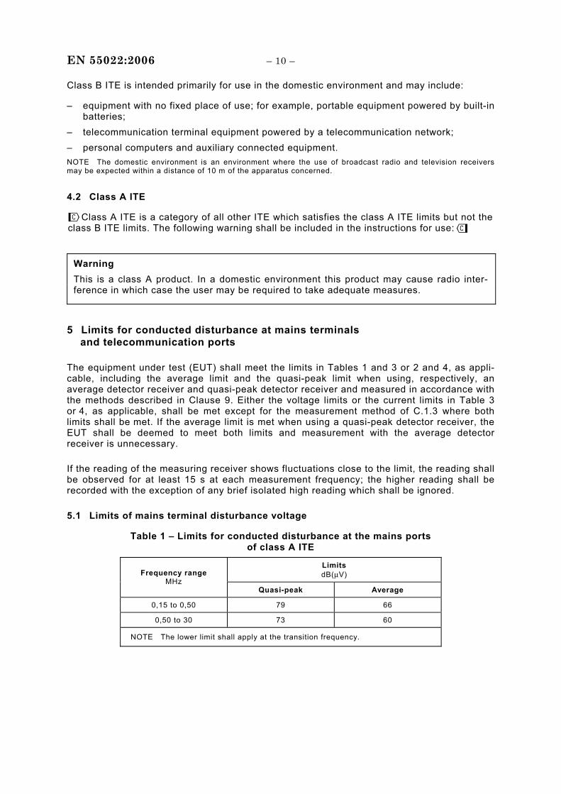
4.2 Class A ITE
Warning This is a class A product. In a domestic environment this product may cause radio inter-ference in which case the user may be required to take adequate measures.
5 Limits for conducted disturbance at mains terminals and telecommunication ports
The equipment under test (EUT) shall meet the limits in Tables 1 and 3 or 2 and 4, as appli-cable, including the average limit and the quasi-peak limit when using, respectively, an average detector receiver and quasi-peak detector receiver and measured in accordance with the methods described in Clause 9. Either the voltage limits or the current limits in Table 3 or 4, as applicable, shall be met except for the measurement method of C.1.3 where both limits shall be met. If the average limit is met when using a quasi-peak detector receiver, the EUT shall be deemed to meet both limits and measurement with the average detector receiver is unnecessary.
If the reading of the measuring receiver shows fluctuations close to the limit, the reading shall be observed for at least 15 s at each measurement frequency; the higher reading shall be recorded with the exception of any brief isolated high reading which shall be ignored.
5.1 Limits of mains terminal disturbance voltage
Table 1 – Limits for conducted disturbance at the mains ports of class A ITE
Limits dB(μV) Frequency range
MHz Quasi-peak Average
0,15 to 0,50 79 66
0,50 to 30 73 60
NOTE The lower limit shall apply at the transition frequency.
Class A ITE is a category of all other ITE which satisfies the class A ITE limits but not the class B ITE limits. The following warning shall be included in the instructions for use:
– 11 – EN 55022:2006
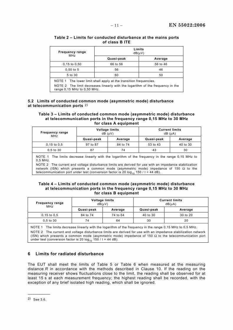
Table 2 – Limits for conducted disturbance at the mains ports of class B ITE
Limits dB(μV) Frequency range
MHz Quasi-peak Average
0,15 to 0,50 66 to 56 56 to 46
0,50 to 5 56 46
5 to 30 60 50
NOTE 1 The lower limit shall apply at the transition frequencies. NOTE 2 The limit decreases linearly with the logarithm of the frequency in the range 0,15 MHz to 0,50 MHz.
5.2 Limits of conducted common mode (asymmetric mode) disturbance at telecommunication ports 2)
Table 3 – Limits of conducted common mode (asymmetric mode) disturbance at telecommunication ports in the frequency range 0,15 MHz to 30 MHz
for class A equipment Voltage limits
dB (μV) Current limits
dB (μA) Frequency range MHz
Quasi-peak Average Quasi-peak Average
0,15 to 0,5 97 to 87 84 to 74 53 to 43 40 to 30
0,5 to 30 87 74 43 30
NOTE 1 The limits decrease linearly with the logarithm of the frequency in the range 0,15 MHz to 0,5 MHz. NOTE 2 The current and voltage disturbance limits are derived for use with an impedance stabilization network (ISN) which presents a common mode (asymmetric mode) impedance of 150 Ω to the telecommunication port under test (conversion factor is 20 log10 150 / I = 44 dB).
Table 4 – Limits of conducted common mode (asymmetric mode) disturbance at telecommunication ports in the frequency range 0,15 MHz to 30 MHz
for class B equipment
Voltage limits dB(μV)
Current limits dB(μA) Frequency range
MHz Quasi-peak Average Quasi-peak Average
0,15 to 0,5 84 to 74 74 to 64 40 to 30 30 to 20
0,5 to 30 74 64 30 20
NOTE 1 The limits decrease linearly with the logarithm of the frequency in the range 0,15 MHz to 0,5 MHz. NOTE 2 The current and voltage disturbance limits are derived for use with an impedance stabilization network (ISN) which presents a common mode (asymmetric mode) impedance of 150 Ω to the telecommunication port under test (conversion factor is 20 log10 150 / I = 44 dB).
6 Limits for radiated disturbance
The EUT shall meet the limits of Table 5 or Table 6 when measured at the measuring distance R in accordance with the methods described in Clause 10. If the reading on the measuring receiver shows fluctuations close to the limit, the reading shall be observed for at least 15 s at each measurement frequency; the highest reading shall be recorded, with the exception of any brief isolated high reading, which shall be ignored.
___________ 2) See 3.6.
EN 55022:2006 – 12 –
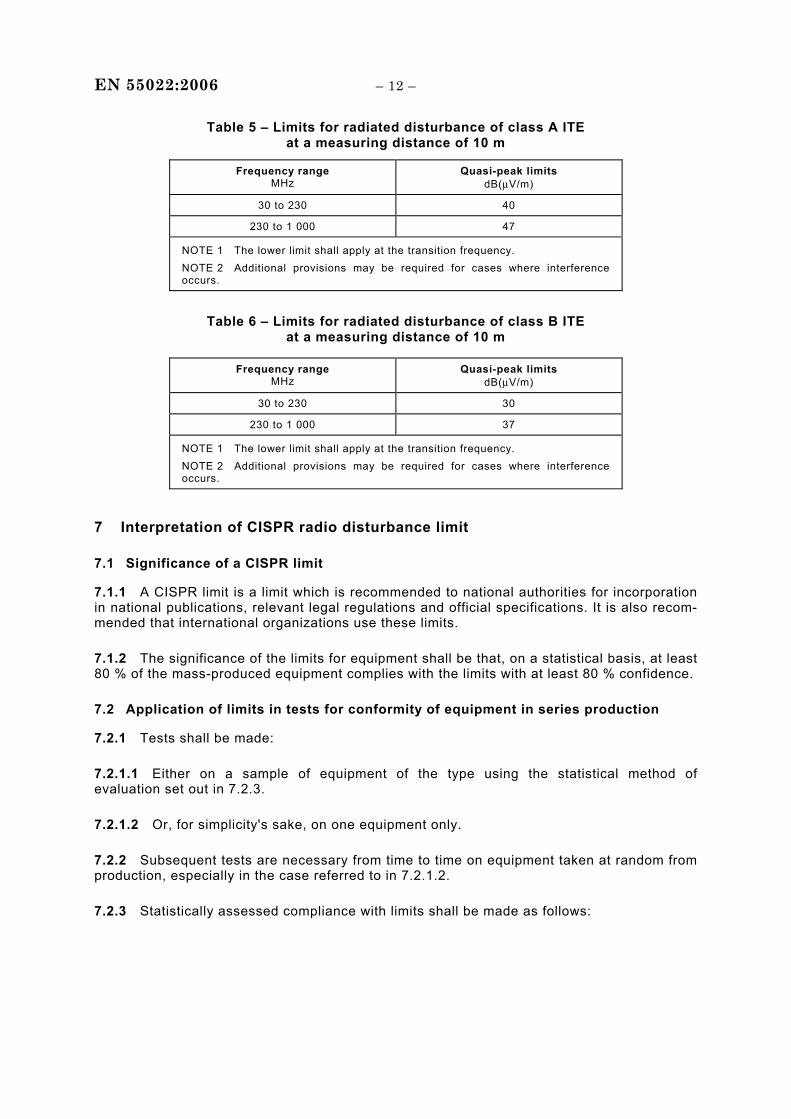
Table 5 – Limits for radiated disturbance of class A ITE at a measuring distance of 10 m
Frequency range MHz
Quasi-peak limits dB(μV/m)
30 to 230 40
230 to 1 000 47
NOTE 1 The lower limit shall apply at the transition frequency. NOTE 2 Additional provisions may be required for cases where interference occurs.
Table 6 – Limits for radiated disturbance of class B ITE at a measuring distance of 10 m
Frequency range MHz
Quasi-peak limits dB(μV/m)
30 to 230 30
230 to 1 000 37
NOTE 1 The lower limit shall apply at the transition frequency. NOTE 2 Additional provisions may be required for cases where interference occurs.
7 Interpretation of CISPR radio disturbance limit
7.1 Significance of a CISPR limit
7.1.1 A CISPR limit is a limit which is recommended to national authorities for incorporation in national publications, relevant legal regulations and official specifications. It is also recom-mended that international organizations use these limits.
7.1.2 The significance of the limits for equipment shall be that, on a statistical basis, at least 80 % of the mass-produced equipment complies with the limits with at least 80 % confidence.
7.2 Application of limits in tests for conformity of equipment in series production
7.2.1 Tests shall be made:
7.2.1.1 Either on a sample of equipment of the type using the statistical method of evaluation set out in 7.2.3.
7.2.1.2 Or, for simplicity's sake, on one equipment only.
7.2.2 Subsequent tests are necessary from time to time on equipment taken at random from production, especially in the case referred to in 7.2.1.2.
7.2.3 Statistically assessed compliance with limits shall be made as follows:
– 13 – EN 55022:2006
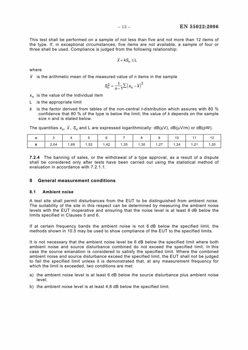
This test shall be performed on a sample of not less than five and not more than 12 items of the type. If, in exceptional circumstances, five items are not available, a sample of four or three shall be used. Compliance is judged from the following relationship:
x kS+ ≤n L
where x is the arithmetic mean of the measured value of n items in the sample
( )S n x xn2
n21
1= − −∑
xn is the value of the individual item L is the appropriate limit k is the factor derived from tables of the non-central t-distribution which assures with 80 %
confidence that 80 % of the type is below the limit; the value of k depends on the sample size n and is stated below.
The quantities xn, x , Sn and L are expressed logarithmically: dB(μV), dB(μV/m) or dB(pW).
n 3 4 5 6 7 8 9 10 11 12
k 2,04 1,69 1,52 1,42 1,35 1,30 1,27 1,24 1,21 1,20
7.2.4 The banning of sales, or the withdrawal of a type approval, as a result of a dispute shall be considered only after tests have been carried out using the statistical method of evaluation in accordance with 7.2.1.1.
8 General measurement conditions
8.1 Ambient noise
A test site shall permit disturbances from the EUT to be distinguished from ambient noise. The suitability of the site in this respect can be determined by measuring the ambient noise levels with the EUT inoperative and ensuring that the noise level is at least 6 dB below the limits specified in Clauses 5 and 6.
If at certain frequency bands the ambient noise is not 6 dB below the specified limit, the methods shown in 10.5 may be used to show compliance of the EUT to the specified limits.
It is not necessary that the ambient noise level be 6 dB below the specified limit where both ambient noise and source disturbance combined do not exceed the specified limit. In this case the source emanation is considered to satisfy the specified limit. Where the combined ambient noise and source disturbance exceed the specified limit, the EUT shall not be judged to fail the specified limit unless it is demonstrated that, at any measurement frequency for which the limit is exceeded, two conditions are met:
a) the ambient noise level is at least 6 dB below the source disturbance plus ambient noise level;
b) the ambient noise level is at least 4,8 dB below the specified limit.
EN 55022:2006 – 14 –
8.2 General arrangement
Where not specified herein, the EUT shall be configured, installed, arranged and operated in a manner consistent with typical applications. Where the manufacturer has specified or recommended an installation practice, this shall be used in the test arrangement, where possible. This arrangement shall be typical of normal installation practice. Interface cables/loads/devices shall be connected to at least one of each type of interface port of the EUT, and where practical, each cable shall be terminated in a device typical of actual usage.
Where there are multiple interface ports of the same type, additional interconnecting cables/ loads/devices may have to be added to the EUT depending upon the results of preliminary tests. Text deleted The rationale for the selection of the configuration and loading of ports shall be included in the test report.
Interconnecting cables should be of the type and length specified in the individual equipment requirements. If the length can be varied, the length shall be selected to produce maximum disturbance.
If shielded or special cables are used during the tests to achieve compliance, then a note shall be included in the instruction manual advising of the need to use such cables.
Excess lengths of cables shall be bundled at the approximate centre of the cable with the bundles 30 cm to 40 cm in length. If it is impractical to do so because of cable bulk or stiffness, or because the testing is being done at a user installation, the disposition of the excess cable shall be precisely noted in the test report.
Where there are multiple interface ports all of the same type, connecting a cable to just one of that type of port is sufficient, provided it can be shown that the additional cables would not significantly affect the results.
Any set of results shall be accompanied by a complete description of the cable and equipment orientation so that results can be repeated. If specific conditions of use are required to meet the limits, those conditions shall be specified and documented; for example cable length, cable type, shielding and grounding. These conditions shall be included in the instructions to the user.
Equipment which is populated with multiple modules (drawer, plug-in card, board, etc.) shall be tested with a mix and number representative of that used in a typical installation. Text deleted The rationale used for selecting the number and type of modules should be stated in the test report.
A system that consists of a number of separate units shall be configured to form a minimum representative configuration. The number and mix of units included in the test configuration shall normally be representative of that used in a typical installation. The rationale used for selecting units should be stated in the test report.
Examples of a minimum representative configuration follow.
– 15 – EN 55022:2006
For a personal computer or a personal computer peripheral, the minimum configuration consists of the following device grouped and tested together:
a) personal computer; b) keyboard; c) visual display unit; d) external peripheral for each of two different types of available I/O protocols, such as
serial, parallel, etc.; e) if the EUT has a dedicated port for a special-purpose device such as a mouse or joystick,
that device shall be part of the minimum configuration. NOTE Items a), b) and/or c) may, in some systems, be assembled in the same chassis. In no instance may items a), b), c) mouse or joystick controls, be used as a replacement for item d).
For a point of sale terminal, the minimum system consists of the following devices (to the extent applicable) grouped and tested together:
a) active processor (till); b) cash drawer; c) keyboard(s); d) display units (operator and customer); e) typical peripheral (bar code scanner); f) handheld device (bar code scanner).
One module of each type shall be operative in each ITE evaluated in an EUT. For a system EUT, one of each type of ITE that can be included in the possible system configuration shall be included in the EUT.
A unit of equipment which forms part of a system distributed over a wide area (such as data processing terminals or workstations, or private branch telecommunication exchanges, etc.), and which in itself may be a subsystem, may be tested independently of the host unit or system. Distributed networks, for example a local area network, may be simulated on the test site by lengths of cable and actual peripherals or remote network communications simulators located at a distance sufficient to ensure that they do not contribute to the measured level.
The results of an evaluation of EUTs having one of each type of module or ITE can be applied to configurations having more than one of each of those modules or ITE. This is permissible because it has been found that disturbances from identical modules or ITE (see 3.5) are generally not additive in practice.
In the case of EUTs which functionally interact with other ITE, including any ITE that is dependent on a host unit for its power interface, either the actual interfacing ITE or simulators may be used to provide representative operating conditions, provided the effects of the simulator can be isolated or identified. If an ITE is designed to be a host unit to other ITE, such ITE may have to be connected in order that the host unit shall operate under normal conditions.
It is important that any simulator used instead of an actual interfacing ITE properly represents the electrical and, in some cases, the mechanical characteristics of the interfacing ITE, especially RF signals and impedances. Following this procedure will permit the results of measurements of individual ITE to remain valid for system application and integration of the ITE with other similarly tested ITE, including ITE produced and tested by different manufacturers.

EN 55022:2006 – 16 –
In the case of printed wiring board assemblies (PWBA), separately marketed for the enhancement of diverse host units, the PWBA (such as ISDN interface, CPU, adaptor cards, etc.) shall be tested in at least one appropriate representative host unit of the PWBA manufacturer's choice so as to ensure compliance of the PWBA with the entire population of hosts in which it is intended to be installed.
The host shall be a typical compliant production sample.
PWBA intended to be class B shall not be tested in hosts which are class A.
The accompanying documentation of the PWBA shall include information regarding the host units in which the PWBA was tested and verified, and information enabling the user to identify host units in which the PWBA will achieve compliance with the classification (A or B).
8.2.1 Determination of maximum emission arrangement(s)
Initial testing shall identify the frequency that has the highest disturbance relative to the limit. This identification shall be performed whilst operating the EUT in typical modes of operation and with cable positions in a test arrangement that is representative of typical installation practice.
The frequency of highest disturbance with respect to the limit shall be found by investigating disturbances at a number of significant frequencies. This provides confidence that the probable frequency of maximum disturbance has been found and that the associated cable, EUT arrangement and mode of operation has been identified.
For initial testing, the EUT should be arranged in accordance with Figures 4 through 13 as appropriate.
Final measurements shall be conducted as in Clauses 9 and 10 for conducted and radiated disturbances, respectively.
8.3 EUT arrangement
The EUT position relative to the ground reference plane shall be equivalent to that occurring in use. Therefore, floor-standing equipment is placed on, but insulated from, a ground reference plane, and tabletop equipment is placed on a non-conductive table.
Equipment designed for wall-mounted operation shall be tested as tabletop EUT. The orientation of the equipment shall be consistent with normal installation practice.
Combinations of the equipment types identified above shall also be arranged in a manner consistent with normal installation practice. Equipment designed for both tabletop and floor standing operation shall be tested as tabletop equipment unless the usual installation is floor standing, then that arrangement shall be used.
The ends of signal cables attached to the EUT that are not connected to another unit, ISN or associated equipment should be terminated, if required, using the correct terminating impedance.
Telecom cables or other connections to associated equipment located outside the test area shall drape to the floor, and then be routed to the place where they leave the test site.
– 17 – EN 55022:2006
Associated equipment shall be installed in accordance with normal installation practice. Where this means that the associated equipment is located on the test site, it shall be arranged using the same conditions applicable for the EUT (for example, distance from ground plane and insulation from the ground plane if floor standing, layout of cabling etc.).
NOTE Specific ground plane requirements are given in 9.4 for conducted disturbance measurements and in 10.4.4 for radiated disturbance measurements, and in 9.5 and 10.5 where they may relate to particular test arrangements.
Figures 4 through Figure 13 are examples of test arrangements and provide guidance only. The requirements stated in the text take precedence.
8.3.1 Tabletop arrangement
The general conditions of 8.3 apply.
Equipment intended for tabletop use shall be placed on a non-conductive table. The size of the table will nominally be 1,5 m × 1,0 m but may ultimately be dependent on the horizontal dimensions of EUT.
All units of equipment forming the system under test (includes the EUT as well as connected peripherals and associated equipment or devices) shall be arranged such that a nominal 0,1 m separation is achieved between the neighbouring units (see Figure 4). Where the units are normally stacked, then they shall be placed directly on top of each other (for example a monitor and desk-top PC) and placed at the rear of the arrangement (peripheral position 1 or 2 in Figure 4).
Ideally, the rear of the arrangement shall be flush with the back of the supporting tabletop unless that would not be possible or typical of normal use. This may require the table to be extended. If this is not possible, then the additional units may be placed around the sides of the table as shown in Figure 4. Positions 1 and 2 shall be used for up to two additional units in Figure 4. If more than two units are present, the test arrangement shall be chosen that maintains as close as practical the 0,1 m spacing between units unless they are normally located closer together.
Intra-unit cables shall be draped over the back of the table. If a cable hangs closer than 0,4 m from the horizontal ground plane (or floor), the excess shall be folded at the cable centre into a bundle no longer than 0,4 m, such that the bundle is at least 0,4 m above the horizontal ground reference plane.
Cables of devices such as keyboards, mice, microphone etc. shall be positioned as for normal usage.
The arrangement of external power supply units shall be as follows:
a) If the mains input cable of the external power supply unit is greater than 0,8 m, the external power supply unit shall be placed on the tabletop, with a nominal 0,1 m separation from the host unit.
b) If the external power supply unit has a mains input cable that is less than 0,8 m, the external power supply unit shall be placed at a height above the ground plane such that its power cable is fully extended in the vertical direction.
EN 55022:2006 – 18 –
c) If the external power supply unit is incorporated into the mains power plug, it shall be placed on the tabletop. An extension cable shall be used between the external power supply unit and the source of power . The extension cable should be connected in a manner such that it takes the most direct path between the external power supply unit and the source of power.
In the above arrangements, the cable between the EUT and the power accessory shall be arranged on the tabletop in the same manner as other cables connecting components of the EUT.
8.3.2 Floor-standing arrangement
The general conditions of 8.3 apply.
The EUT shall be placed on the horizontal ground reference plane, orientated for normal use, but separated from metallic contact with the ground reference plane by up to 15 cm of insulation.
The cables shall be insulated (by up to 15 cm ) from the horizontal ground reference plane. If the equipment requires a dedicated ground connection, then this shall be provided and bonded to the horizontal ground plane.
Intra-unit cables (between units forming the EUT or between the EUT and an associated equipment) shall drape to, but remain insulated from, the horizontal ground reference plane. Any excess shall either be folded at the cable centre into a bundle no longer than 0,4 m or arranged in a serpentine fashion.
If an intra-unit cable length is not long enough to drape to the horizontal ground reference plane but drapes closer than 0,4 m, then the excess shall be folded at the cable centre into a bundle no longer than 0,4 m. The bundle shall be positioned such that it is either 0,4 m above the horizontal ground reference plane or at the height of the cable entry or connection point if this is within 0,4 m of the horizontal ground reference plane (See Figures 8 and 11).
For equipment with a vertical cable riser, the number of risers shall be typical of installation practice. Where the riser is made of non-conductive material, a minimum spacing of at least 0,2 m shall be maintained between the closest part of the equipment and the nearest vertical cable. Where the riser structure is conductive, the minimum spacing of 0,2 m shall be between the closest parts of the equipment and riser structure.
8.3.3 Combinations of tabletop and floor-standing equipment arrangement
Subclauses 8.3.1 and 8.3.2 shall apply with the following additional requirements:
Intra-unit cables between a tabletop unit and a floor standing unit shall have the excess folded into a bundle no longer than 0,4 m. The bundle shall be positioned such that it is either 0,4 m above the horizontal ground reference plane or at the height of the cable entry or connection point if this is within 0,4 m of the horizontal ground reference plane (see Figure 9).
8.4 Operation of the EUT
The operational conditions of the EUT shall be determined by the manufacturer according to the typical use of the EUT with respect to the expected highest level of emission. The determined operational mode and the rationale for the conditions shall be stated in the test report.
– 19 – EN 55022:2006
The EUT shall be operated within the rated (nominal) operating voltage range and typical load conditions (mechanical or electrical) for which it is designed. Actual loads should be used whenever possible. If a simulator is used, it shall represent the actual load with respect to its radio frequency and functional characteristics.
The test programmes or other means of exercising the equipment should ensure that various parts of a system are exercised in a manner that permits detection of all system dis-turbances. For example, in a computer system, tape and disk drives should be put through a read-write-erase sequence; and various portions of memories should be addressed. Any mechanical activities should be performed.
Text deleted
8.5 Operation of multifunction equipment
Multifunction equipment which is subjected simultaneously to different clauses of this standard and/or other standards shall be tested with each function operated in isolation, if this can be achieved without modifying the equipment internally. The equipment thus tested shall be deemed to have complied with the requirements of all clauses/standards when each function has satisfied the requirements of the relevant clause/standard. For example, a personal computer with a broadcast reception function shall be tested with the broadcast reception function inactivated according to CISPR 22 and then tested with only the broadcast reception function activated according to CISPR 13, if the equipment can operate each function in isolation under normal operation.
For equipment which it is not practical to test with each function operated in isolation, or where the isolation of a particular function would result in the equipment being unable to fulfil its primary function, or where the simultaneous operation of several functions would result in saving measurement time, the equipment shall be deemed to have complied if it meets the provisions of the relevant clause/standard with the necessary functions operated. For example, if a personal computer with a broadcast reception function cannot operate the broadcast reception function in isolation from the computing function, the personal computer may be tested with the computing function and broadcast reception function activated according to CISPR 22 and CISPR 13 with respect to these requirements.
Where an allowance is made excluding specific ports or frequencies in a standard, the allowance may be made when relevant functions within multifunction equipment are tested against a different standard (e.g. excluding of fundamental and harmonics frequencies of a local oscillator during a measurement of equipment containing the broadcast reception function according to CISPR 22). In the same way special terminations may be needed, e.g. during the measurements according to CISPR 22, the antenna port of a broadcast receiver shall be terminated by a non-inductive resistor equal to the value of the nominal impedance for the port.
NOTE Disturbances caused by the local oscillator can be distinguished from disturbances caused by other sources by changing the tuned reception frequency/channel.
EN 55022:2006 – 20 –
Regardless of the above prescriptions,
– the measurement of disturbance voltage at the mains port according to CISPR 13 may be excluded if the EUT has complied with the relevant limits of CISPR 22;
– the measurement of disturbance power according to CISPR 13 may be excluded if the EUT has complied with the limits of radiated disturbance field strength of CISPR 22;
– the measurement of radiated disturbance field strength according to CISPR 13 may be excluded if all radiated disturbances from the EUT have complied with the relevant limits of CISPR 22.
9 Method of measurement of conducted disturbance at mains terminals and telecommunication ports
9.1 Measurement detectors
Measurements shall be carried out using quasi-peak and average detector receivers as described in 9.2. Both detectors may be incorporated in a single receiver, and measurements may be carried out by using alternatively the quasi-peak detector and the average detector.
NOTE It is recommended that the measurement of conducted disturbances be performed in a screened enclosure.
To reduce testing time, a peak detector receiver may be used instead of a quasi-peak or an average detector receiver. In case of dispute, measurement with a quasi-peak detector receiver will take precedence when measuring to the quasi-peak limits, and measurement with an average detector receiver will take precedence when measuring to the average limits (see Annex B).
9.2 Measuring receivers
The quasi-peak measuring receiver shall be in accordance with Clause 4 of CISPR 16-1-1.
Receivers with average detectors shall be in accordance with Clause 6 of CISPR 16-1-1, and shall have a 6 dB bandwidth in accordance with Clause 4 of CISPR 16-1-1.
Receivers with peak detectors shall be in accordance with Clause 5 of CISPR 16-1-1 and shall have a 6 dB bandwidth in accordance with Clause 4 of CISPR 16-1-1.
9.3 Artificial mains network (AMN)
An AMN is required to provide a defined impedance at high frequencies across the power feed at the point of measurement of terminal voltage, and also to provide isolation of the circuit under test from the ambient noise on the power lines.
A network with a nominal impedance (50 Ω/50 μH or 50 Ω/50 μH + 5 Ω) as defined in 4.3 of CISPR 16-1-2 shall be utilized.
Conducted disturbances shall be measured between the phase lead and the reference ground, and between the neutral lead and the reference ground. Both measured values shall be within the appropriate limits.
It may not be possible to measure at some frequencies because of conducted ambient noise caused by coupling from local broadcast service fields. A suitable additional radio-frequency filter may be inserted between the AMN and the mains supply, or measurements may be performed in a shielded enclosure. The components forming the additional radio-frequency filter should be enclosed in a metallic screen directly connected to the reference ground of
– 21 – EN 55022:2006
the measuring system. The requirements for the impedance of the AMN should be satisfied at the frequency of the measurement, with the additional radio-frequency filter connected.
9.4 Ground reference plane
A vertical or horizontal ground reference plane shall extend at least 0,5 m beyond the projection of the test arrangement, but shall nevertheless have a minimum size of 2 m × 2 m.
The reference ground point of the AMN and the impedance stabilisation network (ISN) shall be connected to the ground reference plane with a conductor that is as short as possible.
9.5 EUT arrangement
9.5.1 General
The mains cable of the unit being measured shall be connected to one artificial mains network (AMN). Where the EUT is a system, which is a collection of ITE with one or more host units, and each item has its own power cable, the point of connection for the AMN is determined by the following rules:
a) Each power cable that is terminated in a power supply plug of a standard design (IEC 60083 for example) shall be tested separately.
b) Power cables or terminals that are not specified by the manufacturer to be connected via a host unit shall be tested separately.
c) Power cables or field wiring terminals which are specified by the manufacturer to be connected via a host unit or other power-supplying equipment shall be connected to that host unit or other power-supplying equipment, and the terminals or cables of that host unit or other power-supplying equipment are those considered for connection to the AMN and tested.
d) Where a special connection is specified, the necessary hardware to effect the connection shall be supplied by the manufacturer for the purpose of this test.
The AMN shall be placed 0,8 m from the boundary of the unit under test and bonded to a ground reference plane for AMNs mounted on top of the ground reference plane. This distance is between the closest points of the AMN and the EUT. All other units of the EUT and associated equipment shall be at least 0,8 m from the AMN.
Optionally, for AMNs mounted beneath the ground plane, the mains cable connection can be either directly to the AMN or to an extended outlet that is mounted at the surface of the ground plane and connected to the AMN. For mains cable directly connected to AMNs below the ground plane, the 0,8 m separation is between the closest point of the EUT and the ground plane elevation above the AMN. When using an extended outlet attached to the AMN, the impedance requirement of the AMN shall be met at the extended outlet and the 0,8 m separation distance shall be between the closest point of the EUT and the point where the EUT mains cable is connected to the extended outlet.
Where the mains cable supplied by the manufacturer is longer than 1 m, the excess should be folded at the centre into a bundle no longer than 0,4 m, so that its length is shortened to 1 m. If the 1 m cable length cannot be achieved owing to physical limitations of the EUT arrangement, the cable length shall be as near to 1 m as possible. Where the mains cable is not specified or supplied by the manufacturer, a mains cable of 1 m shall be connected between the EUT and AMN.
The power cables of all other units of the equipment under test shall be connected to a second AMN, which is bonded to the ground reference plane in the same way as the AMN for the unit being measured. A multiple socket outlet strip may be used to connect multiple power cables to a single AMN provided the rating of the AMN is not exceeded. Alternatively,
EN 55022:2006 – 22 –
additional AMNs may be used; in this case, the distance between any AMN and any unit shall not be less than 0,8 m.
All telecommunication and signal ports must be correctly terminated using either an appropriate associated equipment or a representative termination during the measurement of the conducted disturbances at the mains. If an ISN is connected to a telecommunications port during the measurement of conducted disturbances at the mains port, then the ISN receiver port shall be terminated in 50 Ω and the LCL shall be representative of the telecommunications network to which that port attaches (for example CAT5).
If ISNs are used for measurements on telecom ports, they shall be nominally 0,8 m from the EUT and bonded to a ground reference plane. Other units of the equipment under test shall be at least 0,8 m from the ISN.
Ground connections, where required for safety purposes, shall be connected to the reference ground point of the AMN and, where not otherwise provided or specified by the manufacturer, shall be of same length as the mains cable and run parallel to the mains connection at a separation distance of not more than 0,1 m.
Other ground connections (for example for EMC purposes), either specified or supplied by the manufacturer for connection to the same ultimate terminal as the safety ground connection, shall also be connected to the reference ground of the AMN.
Where alternative test methods are described in the following subclauses, compliance with the requirements of the subclause may be demonstrated by either or any of the methods described.
9.5.2 Tabletop equipment arrangement
The general conditions of 8.3.1 and 9.5.1 apply.
There are two alternative test arrangements.
1) The test is performed with a vertical ground reference plane. The EUT shall be placed on a non-conductive table such that it is 0,8 m above the horizontal ground reference plane. The rear of the EUT shall be 0,4 m from the vertical ground reference plane. The vertical ground reference plane shall be bonded to the horizontal ground reference plane. Hence the AMN(s) and ISN(s) used can be bonded to either the vertical ground reference plane or other metal planes regarded as the ground reference plane. Example arrangements are shown in Figure 4, Figure 5 (alternative 1a) and Figure 6 (alternative 1b).
2) The test is performed with a horizontal ground reference plane (for example on an open area test site (OATS) or in a screened enclosure). The EUT shall be placed on a non-conductive table such that it is 0,4 m above the horizontal ground reference plane. An example arrangement is shown in Figure 7.
In all cases, the EUT shall be at least 0,8 m from any other metal surface or ground plane, which is not part of the EUT or associated equipment.
It shall be recorded which test arrangement alternative is used for the measurement in the test report.
Additionally:
• AMN(s) may have to be positioned to the side of the table during tabletop testing to meet the criterion that the AMN shall be 0,8 m away from the EUT.
• Signal cables shall be positioned for their entire lengths, as far as possible, at a nominal distance of 0,4 m from the ground reference plane (using a non-conductive fixture, if necessary).
– 23 – EN 55022:2006
Additionally for alternative 2:
• If interface cables would drape over the back of the table, the excess shall be folded at the cable centre into a bundle no longer than 0,4 m, such that the bundle is on the table.
Example arrangements are shown in Figure 4 through Figure 7 inclusive.
9.5.3 Floor-standing equipment arrangement
The general conditions of 8.3.2 and 9.5.1 apply.
Examples of arrangements are shown in Figure 8 and Figure 12.
9.5.4 Combinations of tabletop and floor-standing equipment arrangement
The test arrangement for the tabletop EUT shall be in accordance with 9.5.2.
The test arrangement for the floor-standing EUT shall be in accordance with 9.5.3.
Examples of arrangements are shown in Figure 9 and Figure 13.
9.6 Measurement of disturbances at telecommunication ports
The purpose of these tests is to measure the common mode disturbance emitted at the telecommunication ports of an EUT. The wanted signal may contribute to those common mode disturbances. The common mode disturbances created from the wanted signal can be controlled at the design stage of the interface technology by giving proper consideration to the factors discussed in Annex E.
9.6.1 Methods of conformance testing
Measurement is made at telecommunication ports using ISNs with longitudinal conversion losses (LCL) as defined in 9.6.2.
The manufacturer shall demonstrate that the equipment does not exceed the limits of Tables 3 or 4 when tested with the ISN according to the cable category specified by the equipment documentation provided to the user.
In cases of dispute the method of conformance in 9.6.2 using the appropriate ISN takes precedence for all ports.
9.6.2 Impedance stabilization network (ISN)
The mains voltage shall be supplied to the EUT via the AMN used when measuring the mains terminal disturbance voltages according to 9.3.
Assessment of common mode (asymmetric mode) current or voltage disturbances at telecommunication ports for attachment of unscreened balanced pairs shall be performed with the telecommunication port connected by a cable to an ISN; thus the ISN shall define the common mode termination impedance seen by the telecommunication port during the disturbance measurements. The ISN shall allow normal operation of the EUT, and to this end shall be interposed in the signal cable between the EUT and any auxiliary/associated equipment (AE) or load required to exercise the EUT.
EN 55022:2006 – 24 –
It has not been possible to specify a generally applicable ISN, because the construction depends on the configuration of the telecommunication port under test. Until a suitable ISN is specified for unbalanced cables, it is permitted to connect such cables to an AE or a simulator instead of an ISN. The actual load shall be reported and the common mode impedance shall be measured and stated in the test report. In any case the EUT shall meet the limits in Tables 3 or 4 as applicable.
Where a current probe is used it should be possible to attach it to the cable to be measured without disconnecting the cable from its connections. The current probe must have a uniform frequency response without resonances, and must be capable of operating without saturation effects caused by the operating currents in the primary winding.
The current probe, if used, shall be mounted on the cable within 0,1 m distance of the ISN. The insertion impedance of the current probe must be 1 Ω maximum, see 5.1 of CISPR 16-1-2.
The ISN (calibrated including any and all adapters required to connect to the EUT and AE) shall have the following properties:
a) The common mode termination impedance in the frequency range 0,15 MHz to 30 MHz shall be 150 Ω ± 20 Ω, phase angle 0° ± 20°.
b) The ISN shall provide sufficient isolation against disturbances from an AE or load connected to the telecommunication port under test. The attenuation of the ISN, for common mode current or voltage disturbances originating from the AE, shall be such that the measured level of these disturbances at the measuring receiver input shall be at least 10 dB below the relevant disturbance limit.
The preferred isolation is: • 150 kHz to 1,5 MHz > 35 dB to 55 dB, increasing linearly with the logarithm of the
frequency • 1,5 MHz to 30 MHz > 55 dB. NOTE Isolation is the decoupling of common mode disturbance originating in an AE and subsequently appearing at the EUT port of the ISN.
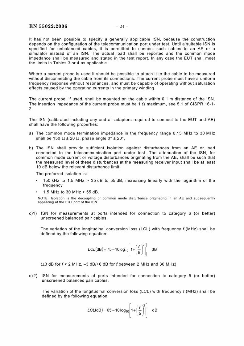
c)1) ISN for measurements at ports intended for connection to category 6 (or better) unscreened balanced pair cables.
The variation of the longitudinal conversion loss (LCL) with frequency f (MHz) shall be defined by the following equation:
( )⎥⎥⎦
⎤
⎢⎢⎣
⎡⎟⎠⎞
⎜⎝⎛+−=
2
10 5110log75dB fLCL dB
(±3 dB for f < 2 MHz, −3 dB/+6 dB for f between 2 MHz and 30 MHz) c) 2) ISN for measurements at ports intended for connection to category 5 (or better)
unscreened balanced pair cables.
The variation of the longitudinal conversion loss (LCL) with frequency f (MHz) shall be defined by the following equation:
( )⎥⎥⎦
⎤
⎢⎢⎣
⎡⎟⎠
⎞⎜⎝
⎛+−=2
10 51log1065dB fLCL dB
– 25 – EN 55022:2006
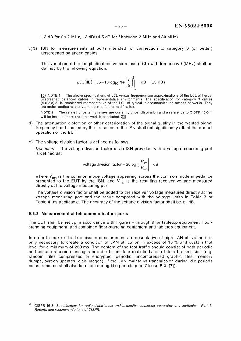
(±3 dB for f < 2 MHz, −3 dB/+4,5 dB for f between 2 MHz and 30 MHz) c) 3) ISN for measurements at ports intended for connection to category 3 (or better)
unscreened balanced cables.
The variation of the longitudinal conversion loss (LCL) with frequency f (MHz) shall be defined by the following equation:
( )⎥⎥⎦
⎤
⎢⎢⎣
⎡⎟⎠
⎞⎜⎝
⎛+−=2
10 51log1055dB fLCL dB (±3 dB)
NOTE 1 The above specifications of LCL versus frequency are approximations of the LCL of typical
unscreened balanced cables in representative environments. The specification for category 3 cables (9.6.2 c) 3) is considered representative of the LCL of typical telecommunication access networks. They are under continuing study and open to future modification.
NOTE 2 The related uncertainty issues are currently under discussion and a reference to CISPR 16-3 3) will be included here once this work is concluded.
d) The attenuation distortion or other deterioration of the signal quality in the wanted signal frequency band caused by the presence of the ISN shall not significantly affect the normal operation of the EUT.
e) The voltage division factor is defined as follows. Definition: The voltage division factor of an ISN provided with a voltage measuring port
is defined as:
dB log20factor division voltagemp
cm10 V
V=
where Vcm is the common mode voltage appearing across the common mode impedance presented to the EUT by the ISN, and Vmp is the resulting receiver voltage measured directly at the voltage measuring port.
The voltage division factor shall be added to the receiver voltage measured directly at the voltage measuring port and the result compared with the voltage limits in Table 3 or Table 4, as applicable. The accuracy of the voltage division factor shall be ±1 dB.
9.6.3 Measurement at telecommunication ports
The EUT shall be set up in accordance with Figures 4 through 9 for tabletop equipment, floor-standing equipment, and combined floor-standing equipment and tabletop equipment.
In order to make reliable emission measurements representative of high LAN utilization it is only necessary to create a condition of LAN utilization in excess of 10 % and sustain that level for a minimum of 250 ms. The content of the test traffic should consist of both periodic and pseudo-random messages in order to emulate realistic types of data transmission (e.g. random: files compressed or encrypted; periodic: uncompressed graphic files, memory dumps, screen updates, disk images). If the LAN maintains transmission during idle periods measurements shall also be made during idle periods (see Clause E.3, [7]).
___________ 3) CISPR 16-3, Specification for radio disturbance and immunity measuring apparatus and methods – Part 3:
Reports and recommendations of CISPR.
EN 55022:2006 – 26 –
9.6.3.1 Voltage measurement at balanced telecommunication ports intended for connection to unscreened balanced pairs
When disturbance voltage measurements are performed, an ISN providing a voltage measuring port suitable for connection to a measuring receiver while satisfying the telecommunication port common mode termination impedance requirements shall be used.
When disturbance voltage measurements are performed on a single unscreened balanced pair, an adequate ISN for two wires shall be used; when performed on unscreened cables containing two balanced pairs, an adequate ISN for four wires shall be used; when performed on unscreened cables containing four balanced pairs, an adequate ISN for eight wires shall be used (see Annex D).
The measurement method of C.1.1 shall be used.
For cables containing more than four balanced pairs, see 9.6.3.5.
Where normal functioning cannot be achieved because of the impact of the ISN on the EUT, the measurement shall be carried out using the method given in 9.6.3.5.
9.6.3.2 Current measurements at balanced telecommunication ports intended for connection to unscreened balanced pairs
When disturbance current measurements are performed on an unscreened cable containing a single balanced pair or two balanced pairs or four balanced pairs, the cable shall be terminated as for disturbance voltage measurements.
The measurement method of C.1.1 shall be used.
For cables containing more than four balanced pairs, see 9.6.3.5.
9.6.3.3 Voltage measurements at telecommunication ports intended for connection to screened cables or to coaxial cables
The measurement method of C.1.1 or C.1.2 shall be used.
9.6.3.4 Current measurements at telecommunication ports intended for connection to screened cables or to coaxial cables
The measurement method of C.1.1 or C.1.2 shall be used.
9.6.3.5 Measurements at telecommunication ports intended for connection to cables containing more than four balanced pairs or to unbalanced cables
The measurement method of C.1.3 or C.1.4 shall be used. At each frequency, the requirements shall be met either by using the method of C.1.3 or by using the method of C.1.4.
NOTE It is allowed to measure with method C.1.3 and then to measure with method C.1.4 only at frequencies for which the limit is exceeded when using method C.1.3.
– 27 – EN 55022:2006
9.7 Recording of measurements
Of those disturbances above (L – 20 dB), where L is the limit level in logarithmic units, record at least the disturbance levels and the frequencies of the six highest disturbances from each mains port and each telecommunication port which comprise the EUT. For the mains port, the current-carrying conductor for each disturbance shall be identified.
In addition, the test report shall include the value of the measurement uncertainty of the measurement instrumentation and its associated connections used in performing the emission tests. See Clause 11.
10 Method of measurement of radiated disturbance
10.1 Measurement detectors
Measurements shall be made with a quasi-peak measuring receiver in the frequency range 30 MHz to 1 000 MHz.
To reduce the testing time, a peak measuring receiver may be used instead of a quasi-peak measuring receiver. In case of dispute, measurement with a quasi-peak measuring receiver will take precedence.
10.2 Measuring receivers
The quasi-peak measuring receiver shall be in accordance with Clause 4 of CISPR 16-1-1. Receivers with peak detectors shall be in accordance with Clause 5 of CISPR 16-1-1 and shall have a 6 dB bandwidth in accordance with Clause 4 of CISPR 16-1-1.
10.3 Antenna
The antenna shall be a balanced dipole. For frequencies of 80 MHz or above, the antenna shall be resonant in length, and for frequencies below 80 MHz it shall have a length equal to the 80 MHz resonant length. Further detailed information is given in Clause 4 of CISPR 16-1-4.
NOTE Other antennas may be used, provided the results can be correlated with the balanced dipole antenna with an acceptable degree of accuracy.
10.3.1 Antenna-to-EUT distance
Measurements of the radiated field shall be made with the antenna located at the horizontal distance from the boundary of the EUT as specified in Clause 6. The boundary of the EUT is defined by an imaginary straight-line periphery describing a simple geometric configuration encompassing the EUT. All ITE intersystem cables and connecting ITE shall be included within this boundary (see also Figure 2).
NOTE If the field-strength measurement at 10 m cannot be made because of high ambient noise levels, or for other reasons, measurement of class B EUTs may be made at a closer distance, for example 3 m. An inverse proportionality factor of 20 dB per decade should be used to normalize the measured data to the specified distance for determining compliance. Care should be taken in the measurement of large EUTs at 3 m at frequencies near 30 MHz, due to near field effects.
EN 55022:2006 – 28 –
10.3.2 Antenna-to-ground distance
The antenna shall be adjusted between 1 m and 4 m in height above the ground plane for maximum meter reading at each test frequency.
10.3.3 Antenna-to-EUT azimuth
Antenna-to-EUT azimuth shall also be varied during the measurements to find the maximum field-strength readings. For measurement purposes, it may be possible to rotate the EUT. When this is not practicable the EUT remains in a fixed position, and measurements are made around the EUT.
10.3.4 Antenna-to-EUT polarization
Antenna-to-EUT polarization (horizontal and vertical) shall be varied during the measurements to find the maximum field-strength readings.
10.4 Measurement site
10.4.1 General
Test sites shall be validated by making site attenuation measurements for both horizontal and vertical polarization fields in the frequency range of 30 MHz to 1 000 MHz.
The distance between the transmitting and receiving antennas shall be the same as the distance used for the radiated disturbance tests of the EUT.
10.4.2 Site attenuation measurements
A measurement site shall be considered acceptable if the horizontal and vertical site attenuation measurements are within ±4 dB of the theoretical site attenuation of an ideal site (see also CISPR 16-1-4).
10.4.3 Open-area test site
The test site shall be flat, free of overhead wires and nearby reflecting structures, sufficiently large to permit antenna placing at the specified distance, and provide adequate separation between antenna, EUT and reflecting structures. Reflecting structures are defined as those in which construction material is primarily conductive. The test site shall be provided with a horizontal metal ground plane described in 10.4.4. Two such test sites are depicted in Figures 1 and 2.
The test site shall satisfy the site attenuation requirements of CISPR 16-1-4 for open-area test sites.
10.4.4 Conducting ground plane
A conducting ground plane shall extend at least 1 m beyond the periphery of the EUT and the largest measuring antenna, and cover the entire area between the EUT and the antenna. It should be of metal with no holes or gaps having dimensions larger than one-tenth of a wavelength at the highest frequency of measurement. A larger size conducting ground plane may be required if the site attenuation requirements of the test site are not satisfied.
– 29 – EN 55022:2006
10.4.5 Alternative test sites
Tests may be conducted on other test sites which do not have the physical characteristics described in 10.4.3 and 10.4.4. Evidence shall be obtained to show that such alternative sites will yield valid results. Such alternative sites are suitable for performing disturbance tests if the site attenuation measurements described in Annex A meet the site attenuation requirements of 10.4.2.
One example of an alternative site is an absorber lined shielded room.
NOTE Annex A will be replaced by the corresponding procedure when specified in CISPR 16-1.
10.5 EUT arrangement
10.5.1 General
Mains cables shall drape to the ground reference plane. They shall then be routed to the mains power outlet.
The mains power outlet shall be bonded to, and should not protrude above, the ground reference plane. If used, the AMN shall be installed under the ground reference plane.
10.5.2 Tabletop equipment arrangement
The general conditions of 8.3.1 and 10.5.1 shall apply.
The EUT shall be placed upon a non-conductive table 0,8 m above the horizontal ground reference plane (see 10.4.4) of the test site.
An example arrangement is shown in Figure 10.
10.5.3 Floor-standing equipment arrangement
The general conditions of 8.3.2 and 10.5.1 shall apply.
Examples of test arrangements are shown in Figure 11 and Figure 12.
10.5.4 Combinations of tabletop and floor-standing equipment arrangement
The test arrangement for the tabletop part of the EUT shall be in accordance with 10.5.2. The test arrangement for the floor-standing part of the EUT shall be in accordance with 10.5.3.
An example test arrangement is shown in Figure 13.
10.6 Recording of measurements
Of those disturbances above (L – 20 dB), where L is the limit level in logarithmic units, record at least the disturbance levels and the frequencies of the six highest disturbances. Record the antenna polarization for each reported disturbance.
In addition, the test report shall include the value of the measurement uncertainty of the measurement instrumentation and its associated connections used in performing the emission tests. See Clause 11.
EN 55022:2006 – 30 –
10.7 Measurement in the presence of high ambient signals
In general, the ambient signals should not exceed the limit. Radiated emanations from the EUT at the point of measurement may, however, be impossible to measure at some frequencies due to ambient noise fields generated by local broadcast services, other man-made devices, and natural sources.
If the ambient signal field strength is high (see Clause 8) at the specified distance, the following methods may be used to show compliance of the EUT.
a) Perform measurements at close-in distances and determine the limit L2 corresponding to the close-in distance d2 by applying the following relation:
L2 = L1 (d1/d2)
where L1 is the specified limit in microvolts per metre (μV/m) at the distance d1. Determine the possible environmental and compliance test conditions stipulated in
Clause 8 using L2 as the new limit for distance d2. b) In the frequency bands where the ambient noise values of Clause 8 are exceeded
(measured values higher than 6 dB below the limit), the disturbance values of the EUT may be interpolated from the adjacent disturbance values. The interpolated value shall lie on the curve describing a continuous function of the disturbance values adjacent to the ambient noise.
c) Another possibility is to use the method described in Annex C of CISPR 11.
10.8 User installation testing
In some cases, measurements of class A ITE at the user's installation might be necessary. These measurements shall be made preferably at the boundary of the user's premises; if such boundary is less than 10 m from the EUT, the measurements shall be made at a distance of 10 m from the EUT.
This form of compliance verification is specific to the installation site, since the site characteristics affect the measurement. Additional type-tested and compliant ITE may be added to the installed system without invalidating the compliance status of the site.
This method of measurement may not be applicable for compliance verification of physically very large ITE (such as some telecommunication centre equipment). For such equipment, methods of measurement and limits are under consideration.
11 Measurement uncertainty
The results of measurements of emissions from ITE shall reference the measurement instrumentation uncertainty considerations contained in CISPR 16-4-2.
Determining compliance with the limits in this standard shall be based on the results of the compliance measurement, not taking into account measurement instrumentation uncertainty. However the measurement uncertainty of the measurement instrumentation and its associated connections between the various instruments in the measurement chain shall be calculated and both the measurement results and the calculated uncertainty shall appear in the test report.
NOTE For in situ measurements, the contribution of uncertainty due to the site itself is excluded from the uncertainty calculation.
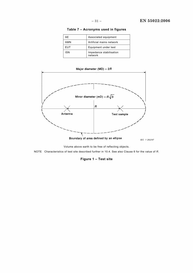
– 31 – EN 55022:2006
Table 7 – Acronyms used in figures
AE Associated equipment
AMN Artificial mains network
EUT Equipment under test
ISN Impedance stabilisation network
IEC 1 262/97
Volume above earth to be free of reflecting objects.
NOTE Characteristics of test site described further in 10.4. See also Clause 6 for the value of R.
Figure 1 – Test site
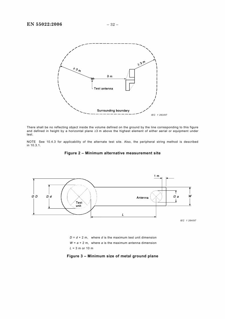
EN 55022:2006 – 32 –
IEC 1 263/97
There shall be no reflecting object inside the volume defined on the ground by the line corresponding to this figure and defined in height by a horizontal plane ≥3 m above the highest element of either aerial or equipment under test.
NOTE See 10.4.3 for applicability of the alternate test site. Also, the peripheral string method is described in 10.3.1.
Figure 2 – Minimum alternative measurement site
IEC 1 264/97
D = d + 2 m, where d is the maximum test unit dimension
W = a + 2 m, where a is the maximum antenna dimension
L = 3 m or 10 m
Figure 3 – Minimum size of metal ground plane
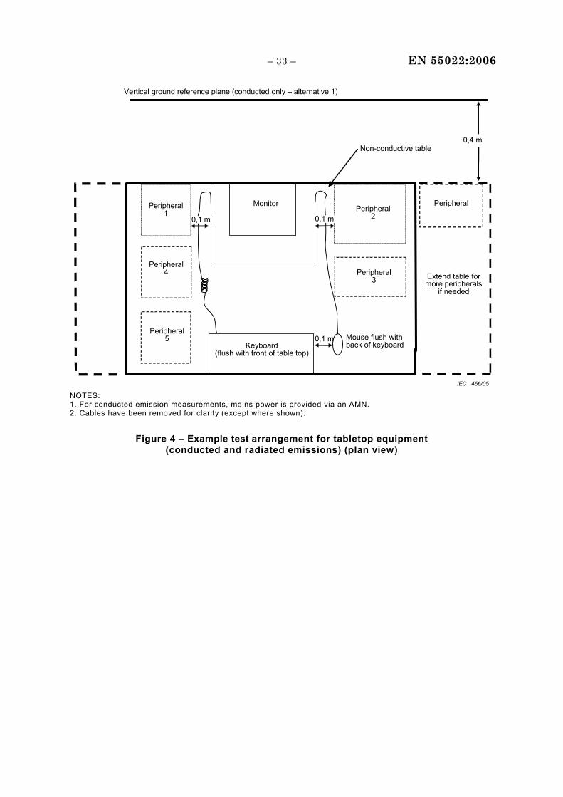
– 33 – EN 55022:2006
Vertical ground reference plane (conducted only – alternative 1)
Monitor
Non-conductive table
Keyboard(flush with front of table top)
Mouse flush with back of keyboard
0,1 m
Peripheral
Extend table for more peripherals
if needed
0,4 m
Peripheral 1
0,1 m0,1 m
Peripheral 4
Peripheral 5
Peripheral2
Peripheral3
IEC 466/05 NOTES: 1. For conducted emission measurements, mains power is provided via an AMN. 2. Cables have been removed for clarity (except where shown).
Figure 4 – Example test arrangement for tabletop equipment (conducted and radiated emissions) (plan view)
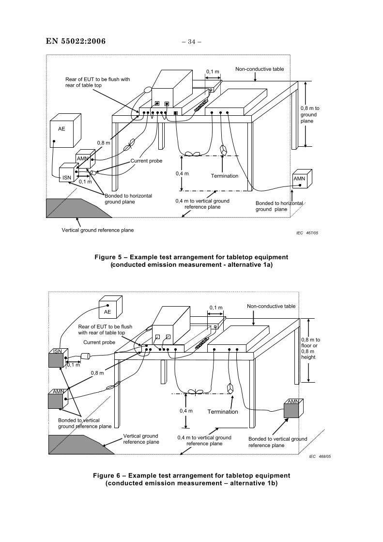
EN 55022:2006 – 34 –
AE
Non-conductive table 0,1 mRear of EUT to be flush with rear of table top
Bonded to horizontal ground plane
ISN
AMN
0,1 m
0,8 m to ground plane
Bonded to horizontal ground plane
Vertical ground reference plane
0,4 m to vertical ground reference plane
Termination
0,8 m
Current probe
AMN 0,4 m
IEC 467/05
Figure 5 – Example test arrangement for tabletop equipment (conducted emission measurement - alternative 1a)
Vertical ground reference plane
0,1 m
AE
ISN
0,1 m
Bonded to vertical ground reference plane
Non-conductive table
AMN
Bonded to vertical ground reference plane
Rear of EUT to be flush with rear of table top
0,8 m to floor or 0,8 m height
0,8 m
0,4 m to vertical ground reference plane
0,4 m Termination
Current probe
AMN
IEC 468/05
Figure 6 – Example test arrangement for tabletop equipment (conducted emission measurement – alternative 1b)
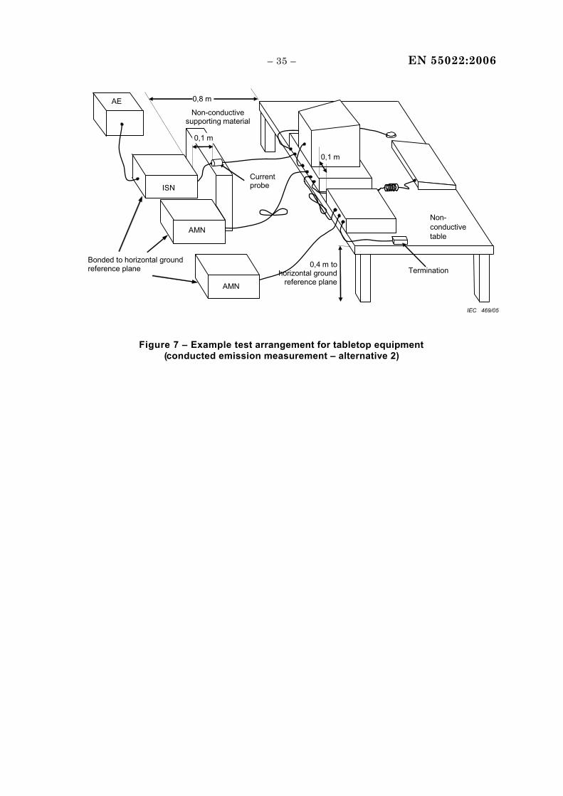
– 35 – EN 55022:2006
0,4 m to horizontal ground
reference plane
Non-conductive table
ISN
AE
AMN
AMN
Non-conductive supporting material
0,8 m
0,1 m
AMN
0,1 m
Current probe
Termination Bonded to horizontal ground reference plane
AE
IEC 469/05
Figure 7 – Example test arrangement for tabletop equipment (conducted emission measurement – alternative 2)
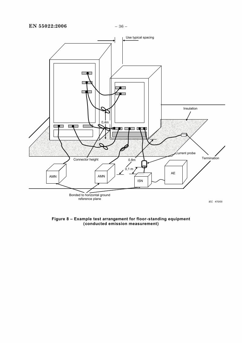
EN 55022:2006 – 36 –
Bonded to horizontal ground reference plane
0,8m
0,1 m
Use typical spacing
0,4m
Insulation
AMN
Current probe Termination
AMNAE
Connector height
ISN
IEC 470/05
Figure 8 – Example test arrangement for floor-standing equipment (conducted emission measurement)
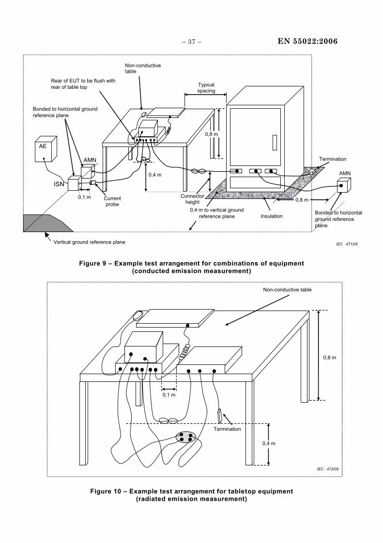
– 37 – EN 55022:2006
Termination
Rear of EUT to be flush with rear of table top
Bonded to horizontal ground reference plane
Vertical ground reference plane
EUT
AMN
Bonded to horizontal ground reference plane
ISN
AMN
0,1 m Current probe
Insulation
Connector height
0,4 m to vertical ground reference plane
0,4 m
Non-conductive table
Typical spacing
0,8 m
AE
0,8 m
IEC 471/05
Figure 9 – Example test arrangement for combinations of equipment
(conducted emission measurement)
0,4 m
Termination
0,1 m
0,8 m
Non-conductive table
IEC 472/05
Figure 10 – Example test arrangement for tabletop equipment
(radiated emission measurement)
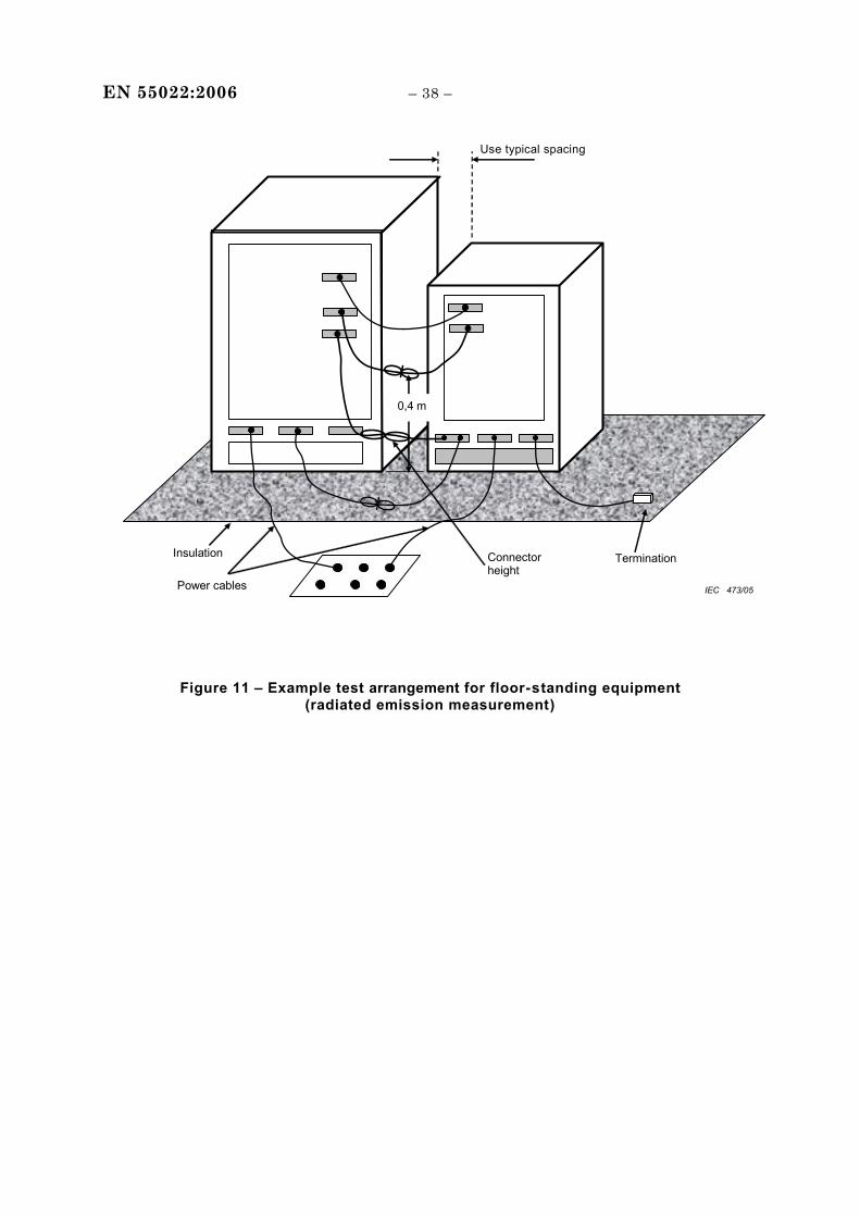
EN 55022:2006 – 38 –
Use typical spacing
0,4 m
Termination Insulation Connector height
Power cables IEC 473/05
Figure 11 – Example test arrangement for floor-standing equipment (radiated emission measurement)
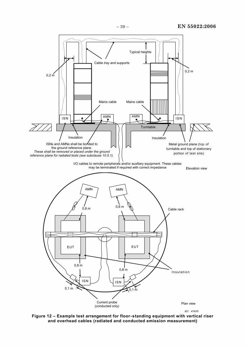
– 39 – EN 55022:2006
0,2 m
Cable tray and supports
Metal ground plane (top of turntable and top of stationary
portion of test site)
Turntable
AMN
Mains cable
I/O cables to remote peripherals and/or auxiliary equipment. These cables may be terminated if required with correct impedance
0,2 m
Mains cable
ISN AMN ISN
ISNs and AMNs shall be bonded to the ground reference plane.
These shall be removed or placed under the ground reference plane for radiated tests (see subclause 10.5.1).
Insulation Insulation
Elevation view
Typical heights
Cable rack
EUT EUT
AMN AMN
0,8 m 0,8 m
ISN
0,8 m 0,8 m
ISN
0,1 m 0,1 m
Current probe (conducted only)
Insu la t ion
Plan view
IEC 474/05 Figure 12 – Example test arrangement for floor-standing equipment with vertical riser
and overhead cables (radiated and conducted emission measurement)
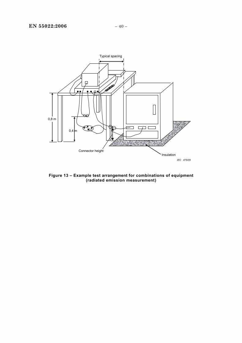
EN 55022:2006 – 40 –
Typical spacing
0,4 m
Insulation
0,8 m
Connector height
IEC 475/05
Figure 13 – Example test arrangement for combinations of equipment (radiated emission measurement)
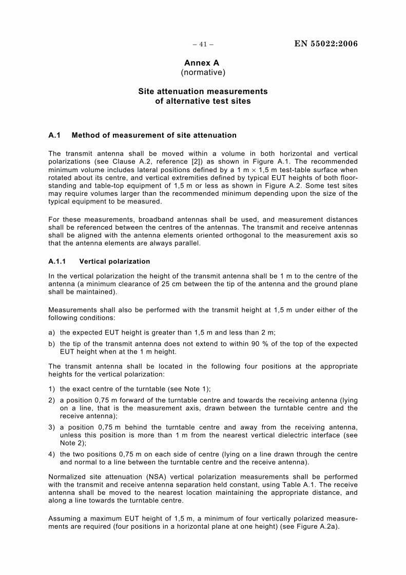
– 41 – EN 55022:2006
Annex A (normative)
Site attenuation measurements
of alternative test sites
A.1 Method of measurement of site attenuation
The transmit antenna shall be moved within a volume in both horizontal and vertical polarizations (see Clause A.2, reference [2]) as shown in Figure A.1. The recommended minimum volume includes lateral positions defined by a 1 m × 1,5 m test-table surface when rotated about its centre, and vertical extremities defined by typical EUT heights of both floor-standing and table-top equipment of 1,5 m or less as shown in Figure A.2. Some test sites may require volumes larger than the recommended minimum depending upon the size of the typical equipment to be measured.
For these measurements, broadband antennas shall be used, and measurement distances shall be referenced between the centres of the antennas. The transmit and receive antennas shall be aligned with the antenna elements oriented orthogonal to the measurement axis so that the antenna elements are always parallel.
A.1.1 Vertical polarization
In the vertical polarization the height of the transmit antenna shall be 1 m to the centre of the antenna (a minimum clearance of 25 cm between the tip of the antenna and the ground plane shall be maintained).
Measurements shall also be performed with the transmit height at 1,5 m under either of the following conditions:
a) the expected EUT height is greater than 1,5 m and less than 2 m; b) the tip of the transmit antenna does not extend to within 90 % of the top of the expected
EUT height when at the 1 m height.
The transmit antenna shall be located in the following four positions at the appropriate heights for the vertical polarization:
1) the exact centre of the turntable (see Note 1); 2) a position 0,75 m forward of the turntable centre and towards the receiving antenna (lying
on a line, that is the measurement axis, drawn between the turntable centre and the receive antenna);
3) a position 0,75 m behind the turntable centre and away from the receiving antenna, unless this position is more than 1 m from the nearest vertical dielectric interface (see Note 2);
4) the two positions 0,75 m on each side of centre (lying on a line drawn through the centre and normal to a line between the turntable centre and the receive antenna).
Normalized site attenuation (NSA) vertical polarization measurements shall be performed with the transmit and receive antenna separation held constant, using Table A.1. The receive antenna shall be moved to the nearest location maintaining the appropriate distance, and along a line towards the turntable centre.
Assuming a maximum EUT height of 1,5 m, a minimum of four vertically polarized measure-ments are required (four positions in a horizontal plane at one height) (see Figure A.2a).
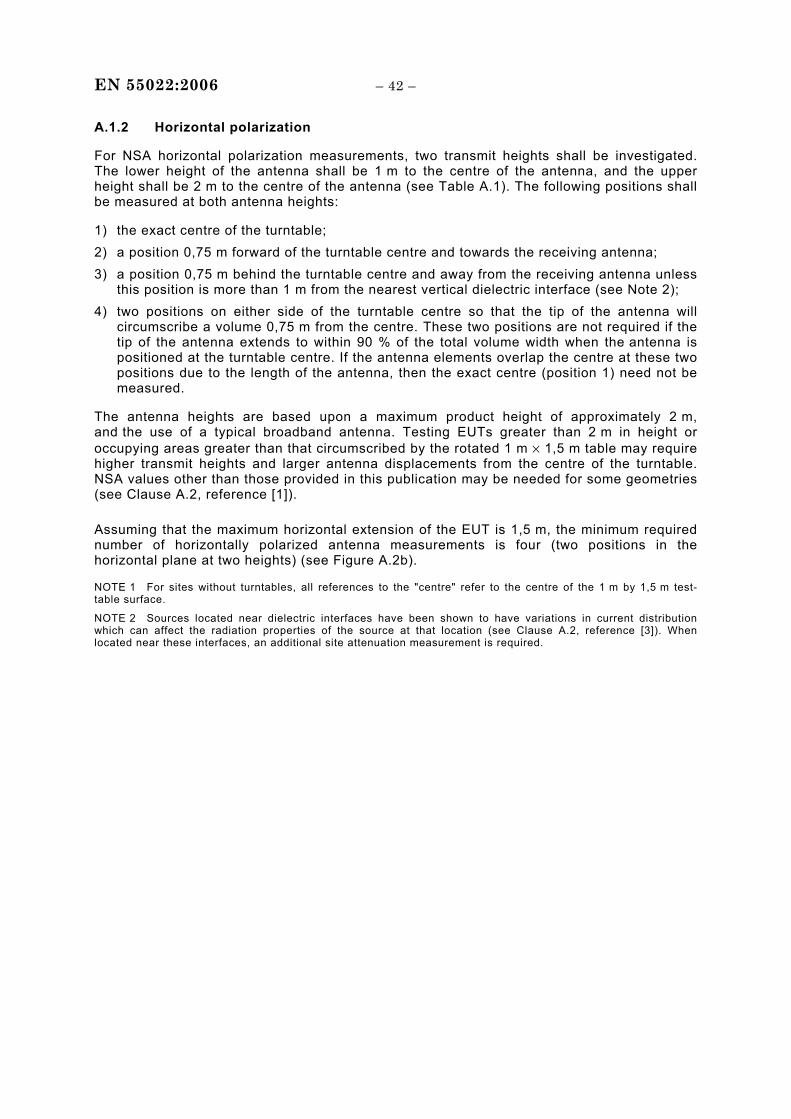
EN 55022:2006 – 42 –
A.1.2 Horizontal polarization
For NSA horizontal polarization measurements, two transmit heights shall be investigated. The lower height of the antenna shall be 1 m to the centre of the antenna, and the upper height shall be 2 m to the centre of the antenna (see Table A.1). The following positions shall be measured at both antenna heights:
1) the exact centre of the turntable; 2) a position 0,75 m forward of the turntable centre and towards the receiving antenna; 3) a position 0,75 m behind the turntable centre and away from the receiving antenna unless
this position is more than 1 m from the nearest vertical dielectric interface (see Note 2); 4) two positions on either side of the turntable centre so that the tip of the antenna will
circumscribe a volume 0,75 m from the centre. These two positions are not required if the tip of the antenna extends to within 90 % of the total volume width when the antenna is positioned at the turntable centre. If the antenna elements overlap the centre at these two positions due to the length of the antenna, then the exact centre (position 1) need not be measured.
The antenna heights are based upon a maximum product height of approximately 2 m, and the use of a typical broadband antenna. Testing EUTs greater than 2 m in height or occupying areas greater than that circumscribed by the rotated 1 m × 1,5 m table may require higher transmit heights and larger antenna displacements from the centre of the turntable. NSA values other than those provided in this publication may be needed for some geometries (see Clause A.2, reference [1]).
Assuming that the maximum horizontal extension of the EUT is 1,5 m, the minimum required number of horizontally polarized antenna measurements is four (two positions in the horizontal plane at two heights) (see Figure A.2b).
NOTE 1 For sites without turntables, all references to the "centre" refer to the centre of the 1 m by 1,5 m test-table surface.
NOTE 2 Sources located near dielectric interfaces have been shown to have variations in current distribution which can affect the radiation properties of the source at that location (see Clause A.2, reference [3]). When located near these interfaces, an additional site attenuation measurement is required.
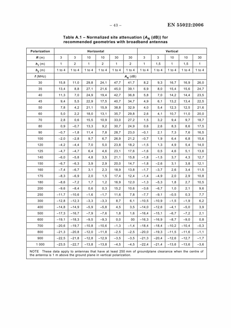
– 43 – EN 55022:2006
Table A.1 – Normalized site attenuation (AN (dB)) for recommended geometries with broadband antennas
Polarization Horizontal Vertical
R (m) 3 3 10 10 30 30 3 3 10 10 30
h1 (m) 1 2 1 2 1 2 1 1,5 1 1,5 1
h2 (m) 1 to 4 1 to 4 1 to 4 1 to 4 1 to 4 1 to 4 1 to 4 1 to 4 1 to 4 1 to 4 1 to 4
f (MHz) AN (dB)
30 15,8 11,0 29,8 24,1 47,7 41,7 8,2 9,3 16,7 16,9 26,0
35 13,4 8,8 27,1 21,6 45,0 39,1 6,9 8,0 15,4 15,6 24,7
40 11,3 7,0 24,9 19,4 42,7 36,8 5,8 7,0 14,2 14,4 23,5
45 9,4 5,5 22,9 17,5 40,7 34,7 4,9 6,1 13,2 13,4 22,5
50 7,8 4,2 21,1 15,9 38,8 32,9 4,0 5,4 12,3 12,5 21,6
60 5,0 2,2 18,0 13,1 35,7 29,8 2,6 4,1 10,7 11,0 20,0
70 2,8 0,6 15,5 10,9 33,0 27,2 1,5 3,2 9,4 9,7 18,7
80 0,9 –0,7 13,3 9,2 30,7 24,9 0,6 2,6 8,3 8,6 17,5
90 –0,7 –1,8 11,4 7,8 28,7 23,0 –0,1 2,1 7,3 7,6 16,5
100 –2,0 –2,8 9,7 6,7 26,9 21,2 –0,7 1,9 6,4 6,8 15,6
120 –4,2 –4,4 7,0 5,0 23,8 18,2 –1,5 1,3 4,9 5,4 14,0
125 –4,7 –4,7 6,4 4,6 23,1 17,6 –1,6 0,5 4,6 5,1 13,6
140 –6,0 –5,8 4,8 3,5 21,1 15,8 –1,8 –1,5 3,7 4,3 12,7
150 –6,7 –6,3 3,9 2,9 20,0 14,7 –1,8 –2,6 3,1 3,8 12,1
160 –7,4 –6,7 3,1 2,3 18,9 13,8 –1,7 –3,7 2,6 3,4 11,5
175 –8,3 –6,9 2,0 1,5 17,4 12,4 –1,4 –4,9 2,0 2,9 10,8
180 –8,6 –7,2 1,7 1,2 16,9 12,0 –1,3 –5,3 1,8 2,7 10,5
200 –9,6 –8,4 0,6 0,3 15,2 10,6 –3,6 –6,7 1,0 2,1 9,6
250 –11,7 –10,6 –1,6 –1,7 11,6 7,8 –7,7 –9,1 –0,5 0,3 7,7
300 –12,8 –12,3 –3,3 –3,3 8,7 6,1 –10,5 –10,9 –1,5 –1,9 6,2
400 –14,8 –14,9 –5,9 –5,8 4,5 3,5 –14,0 –12,6 –4,1 –5,0 3,9
500 –17,3 –16,7 –7,9 –7,6 1,8 1,6 –16,4 –15,1 –6,7 –7,2 2,1
600 –19,1 –18,3 –9,5 –9,3 0,0 00 –16,3 –16,9 –8,7 –9,0 0,8
700 –20,6 –19,7 –10,8 –10,6 –1,3 –1,4 –18,4 –18,4 –10,2 –10,4 –0,3
800 –21,3 –20,8 –12,0 –11,8 –2,5 –2,5 –20,0 –19,3 –11,5 –11,6 –1,1
900 –22,5 –21,8 –12,8 –12,9 –3,5 –3,5 –21,3 –20,4 –12,6 –12,7 –1,7
1 000 –23,5 –22,7 –13,8 –13,8 –4,5 –4,5 –22,4 –21,4 –13,6 –13,6 –3,6
NOTE These data apply to antennas that have at least 250 mm of groundplane clearance when the centre of the antenna is 1 m above the ground plane in vertical polarization.
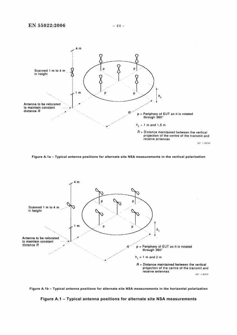
EN 55022:2006 – 44 –
Figure A.1a – Typical antenna positions for alternate site NSA measurements in the vertical polarization
Figure A.1b – Typical antenna positions for alternate site NSA measurements in the horizontal polarization
Figure A.1 – Typical antenna positions for alternate site NSA measurements
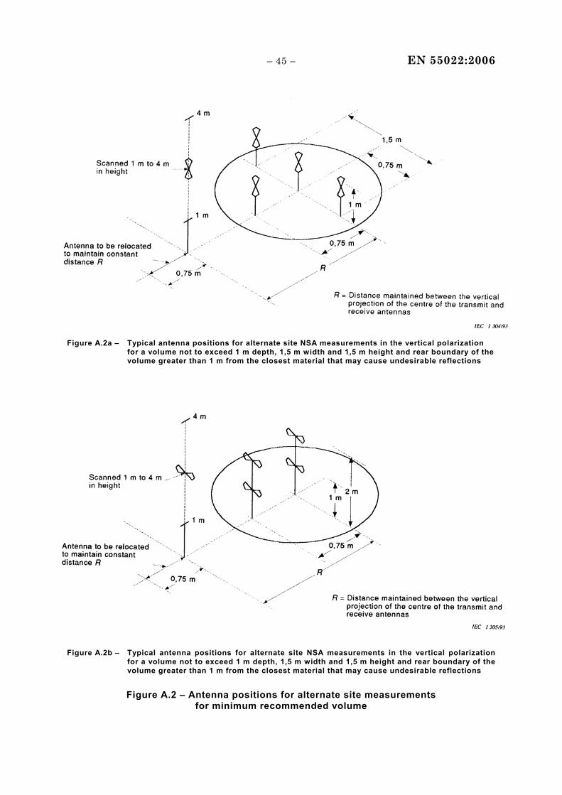
– 45 – EN 55022:2006
Figure A.2a – Typical antenna positions for alternate site NSA measurements in the vertical polarization for a volume not to exceed 1 m depth, 1,5 m width and 1,5 m height and rear boundary of the volume greater than 1 m from the closest material that may cause undesirable reflections
Figure A.2b – Typical antenna positions for alternate site NSA measurements in the vertical polarization for a volume not to exceed 1 m depth, 1,5 m width and 1,5 m height and rear boundary of the volume greater than 1 m from the closest material that may cause undesirable reflections
Figure A.2 – Antenna positions for alternate site measurements for minimum recommended volume
EN 55022:2006 – 46 –
A.2 References
[1] SMITH, A.A., GERMAN, R.F., PATE, J.B., "Calculation of site attenuation from antenna factors", IEEE Transactions on EMC, Vol EMC-24, 1982.
[2] GERMAN, R.F., "Comparison of semi-anechoic chamber and open-field site attenuation measurements", 1982 IEEE International Symposium Record on Electromagnetic Compatibility, pp 260-265.
[3] PATE, J.B., "Potential measurement errors due to mutual coupling between dipole antennas and radio frequency absorbing material in close proximity", 1984 IEEE National Symposium Record on Electromagnetic Compatibility.
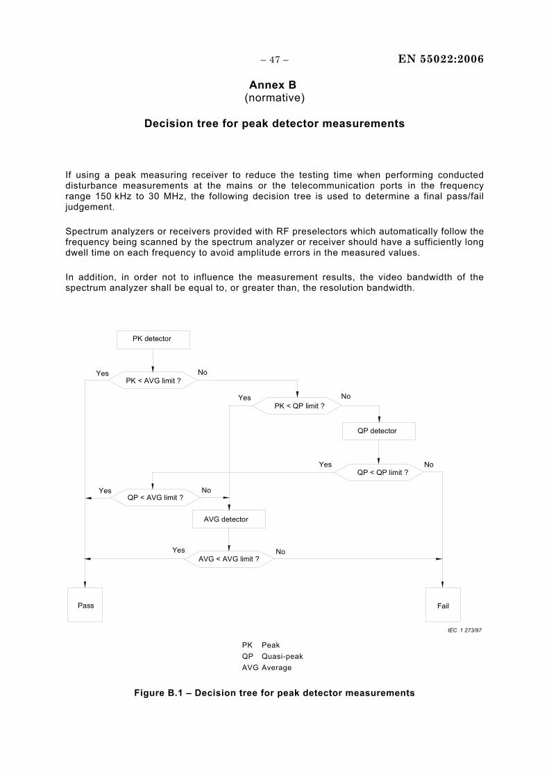
– 47 – EN 55022:2006
Annex B (normative)
Decision tree for peak detector measurements
If using a peak measuring receiver to reduce the testing time when performing conducted disturbance measurements at the mains or the telecommunication ports in the frequency range 150 kHz to 30 MHz, the following decision tree is used to determine a final pass/fail judgement.
Spectrum analyzers or receivers provided with RF preselectors which automatically follow the frequency being scanned by the spectrum analyzer or receiver should have a sufficiently long dwell time on each frequency to avoid amplitude errors in the measured values.
In addition, in order not to influence the measurement results, the video bandwidth of the spectrum analyzer shall be equal to, or greater than, the resolution bandwidth.
PK detector
QP < AVG limit ?
QP detector
QP < QP limit ?
AVG detector
AVG < AVG limit ?
PK < QP limit ?
PK < AVG limit ?
Pass Fail
Yes No
NoYes
Yes No
NoYes
Yes No
IEC 1 273/97 PK Peak QP Quasi-peak AVG Average
Figure B.1 – Decision tree for peak detector measurements
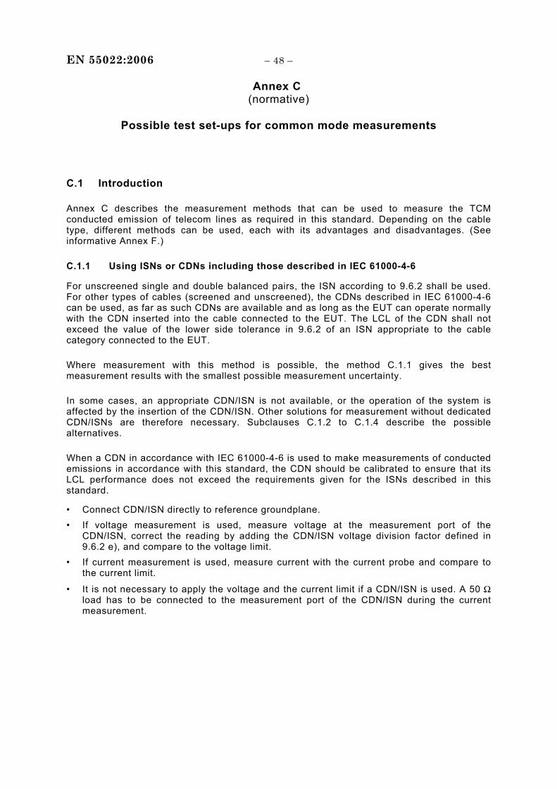
EN 55022:2006 – 48 –
Annex C (normative)
Possible test set-ups for common mode measurements
C.1 Introduction
Annex C describes the measurement methods that can be used to measure the TCM conducted emission of telecom lines as required in this standard. Depending on the cable type, different methods can be used, each with its advantages and disadvantages. (See informative Annex F.)
C.1.1 Using ISNs or CDNs including those described in IEC 61000-4-6
For unscreened single and double balanced pairs, the ISN according to 9.6.2 shall be used. For other types of cables (screened and unscreened), the CDNs described in IEC 61000-4-6 can be used, as far as such CDNs are available and as long as the EUT can operate normally with the CDN inserted into the cable connected to the EUT. The LCL of the CDN shall not exceed the value of the lower side tolerance in 9.6.2 of an ISN appropriate to the cable category connected to the EUT.
Where measurement with this method is possible, the method C.1.1 gives the best measurement results with the smallest possible measurement uncertainty.
In some cases, an appropriate CDN/ISN is not available, or the operation of the system is affected by the insertion of the CDN/ISN. Other solutions for measurement without dedicated CDN/ISNs are therefore necessary. Subclauses C.1.2 to C.1.4 describe the possible alternatives.
When a CDN in accordance with IEC 61000-4-6 is used to make measurements of conducted emissions in accordance with this standard, the CDN should be calibrated to ensure that its LCL performance does not exceed the requirements given for the ISNs described in this standard.
• Connect CDN/ISN directly to reference groundplane. • If voltage measurement is used, measure voltage at the measurement port of the
CDN/ISN, correct the reading by adding the CDN/ISN voltage division factor defined in 9.6.2 e), and compare to the voltage limit.
• If current measurement is used, measure current with the current probe and compare to the current limit.
• It is not necessary to apply the voltage and the current limit if a CDN/ISN is used. A 50 Ω load has to be connected to the measurement port of the CDN/ISN during the current measurement.
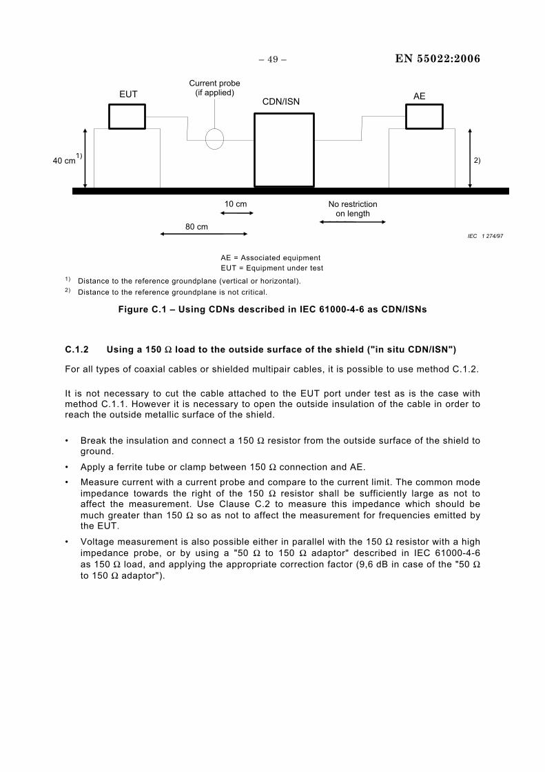
– 49 – EN 55022:2006
EUT AE
40 cm1)
2)
Current probe(if applied)
CDN/ISN
80 cm
No restriction on length
10 cm
IEC 1 274/97
AE = Associated equipment
EUT = Equipment under test 1) Distance to the reference groundplane (vertical or horizontal). 2) Distance to the reference groundplane is not critical.
Figure C.1 – Using CDNs described in IEC 61000-4-6 as CDN/ISNs
C.1.2 Using a 150 Ω load to the outside surface of the shield ("in situ CDN/ISN")
For all types of coaxial cables or shielded multipair cables, it is possible to use method C.1.2.
It is not necessary to cut the cable attached to the EUT port under test as is the case with method C.1.1. However it is necessary to open the outside insulation of the cable in order to reach the outside metallic surface of the shield.
• Break the insulation and connect a 150 Ω resistor from the outside surface of the shield to ground.
• Apply a ferrite tube or clamp between 150 Ω connection and AE. • Measure current with a current probe and compare to the current limit. The common mode
impedance towards the right of the 150 Ω resistor shall be sufficiently large as not to affect the measurement. Use Clause C.2 to measure this impedance which should be much greater than 150 Ω so as not to affect the measurement for frequencies emitted by the EUT.
• Voltage measurement is also possible either in parallel with the 150 Ω resistor with a high impedance probe, or by using a "50 Ω to 150 Ω adaptor" described in IEC 61000-4-6 as 150 Ω load, and applying the appropriate correction factor (9,6 dB in case of the "50 Ω to 150 Ω adaptor").
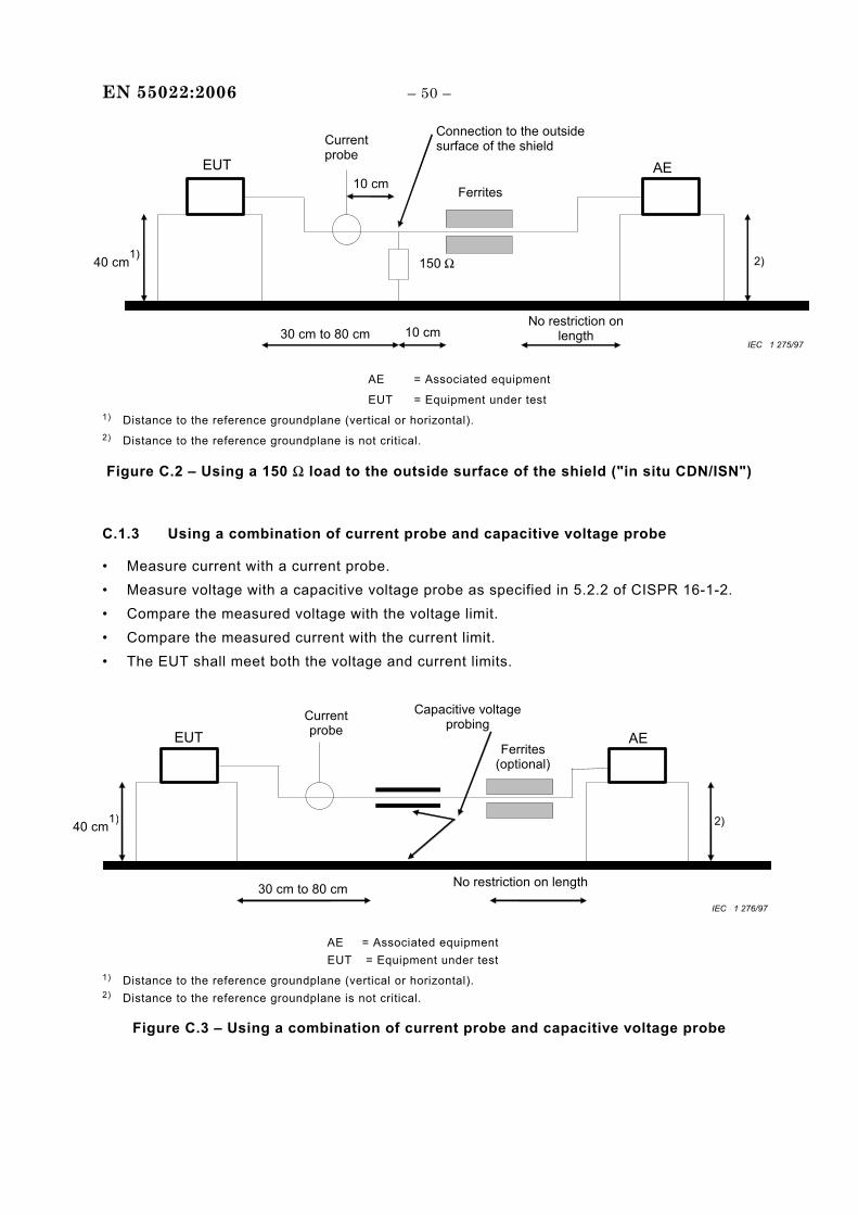
EN 55022:2006 – 50 –
EUT AE
40 cm1)
10 cm Ferrites
150 Ω 2)
Current probe
Connection to the outside surface of the shield
30 cm to 80 cm 10 cm No restriction on
length IEC 1 275/97
AE = Associated equipment
EUT = Equipment under test 1) Distance to the reference groundplane (vertical or horizontal). 2) Distance to the reference groundplane is not critical.
Figure C.2 – Using a 150 Ω load to the outside surface of the shield ("in situ CDN/ISN")
C.1.3 Using a combination of current probe and capacitive voltage probe
• Measure current with a current probe. • Measure voltage with a capacitive voltage probe as specified in 5.2.2 of CISPR 16-1-2. • Compare the measured voltage with the voltage limit. • Compare the measured current with the current limit. • The EUT shall meet both the voltage and current limits.
40 cm1)
2)
Current probe
Capacitive voltage probing
30 cm to 80 cm No restriction on length
AE EUT Ferrites
(optional)
IEC 1 276/97
AE = Associated equipment EUT = Equipment under test
1) Distance to the reference groundplane (vertical or horizontal). 2) Distance to the reference groundplane is not critical.
Figure C.3 – Using a combination of current probe and capacitive voltage probe
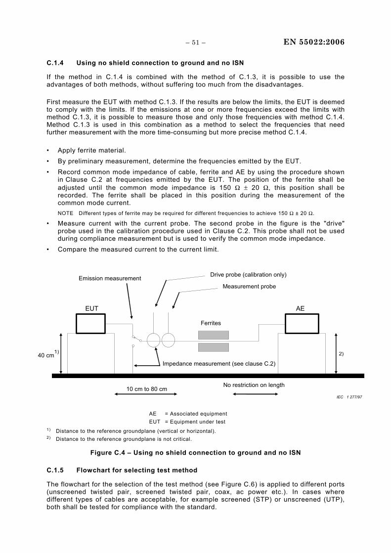
– 51 – EN 55022:2006
C.1.4 Using no shield connection to ground and no ISN
If the method in C.1.4 is combined with the method of C.1.3, it is possible to use the advantages of both methods, without suffering too much from the disadvantages.
First measure the EUT with method C.1.3. If the results are below the limits, the EUT is deemed to comply with the limits. If the emissions at one or more frequencies exceed the limits with method C.1.3, it is possible to measure those and only those frequencies with method C.1.4. Method C.1.3 is used in this combination as a method to select the frequencies that need further measurement with the more time-consuming but more precise method C.1.4.
• Apply ferrite material. • By preliminary measurement, determine the frequencies emitted by the EUT. • Record common mode impedance of cable, ferrite and AE by using the procedure shown
in Clause C.2 at frequencies emitted by the EUT. The position of the ferrite shall be adjusted until the common mode impedance is 150 Ω ± 20 Ω, this position shall be recorded. The ferrite shall be placed in this position during the measurement of the common mode current. NOTE Different types of ferrite may be required for different frequencies to achieve 150 Ω ± 20 Ω.
• Measure current with the current probe. The second probe in the figure is the "drive" probe used in the calibration procedure used in Clause C.2. This probe shall not be used during compliance measurement but is used to verify the common mode impedance.
• Compare the measured current to the current limit.
EUT AE
40 cm1)
Ferrites
2)
Measurement probe
10 cm to 80 cm No restriction on length
Drive probe (calibration only) Emission measurement
Impedance measurement (see clause C.2)
IEC 1 277/97
AE = Associated equipment EUT = Equipment under test
1) Distance to the reference groundplane (vertical or horizontal). 2) Distance to the reference groundplane is not critical.
Figure C.4 – Using no shield connection to ground and no ISN
C.1.5 Flowchart for selecting test method
The flowchart for the selection of the test method (see Figure C.6) is applied to different ports (unscreened twisted pair, screened twisted pair, coax, ac power etc.). In cases where different types of cables are acceptable, for example screened (STP) or unscreened (UTP), both shall be tested for compliance with the standard.
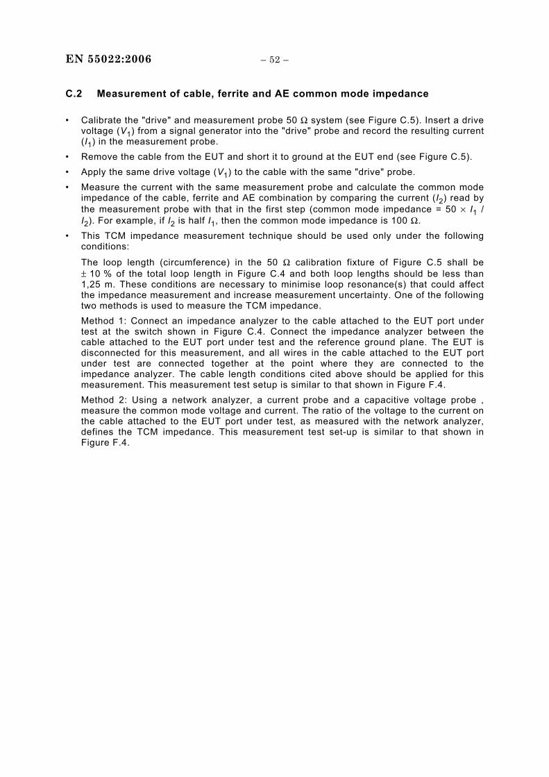
EN 55022:2006 – 52 –
C.2 Measurement of cable, ferrite and AE common mode impedance
• Calibrate the "drive" and measurement probe 50 Ω system (see Figure C.5). Insert a drive voltage (V1) from a signal generator into the "drive" probe and record the resulting current (I1) in the measurement probe.
• Remove the cable from the EUT and short it to ground at the EUT end (see Figure C.5). • Apply the same drive voltage (V1) to the cable with the same "drive" probe. • Measure the current with the same measurement probe and calculate the common mode
impedance of the cable, ferrite and AE combination by comparing the current (I2) read by the measurement probe with that in the first step (common mode impedance = 50 × I1 / I2). For example, if I2 is half I1, then the common mode impedance is 100 Ω.
• This TCM impedance measurement technique should be used only under the following conditions:
The loop length (circumference) in the 50 Ω calibration fixture of Figure C.5 shall be ± 10 % of the total loop length in Figure C.4 and both loop lengths should be less than 1,25 m. These conditions are necessary to minimise loop resonance(s) that could affect the impedance measurement and increase measurement uncertainty. One of the following two methods is used to measure the TCM impedance.
Method 1: Connect an impedance analyzer to the cable attached to the EUT port under test at the switch shown in Figure C.4. Connect the impedance analyzer between the cable attached to the EUT port under test and the reference ground plane. The EUT is disconnected for this measurement, and all wires in the cable attached to the EUT port under test are connected together at the point where they are connected to the impedance analyzer. The cable length conditions cited above should be applied for this measurement. This measurement test setup is similar to that shown in Figure F.4.
Method 2: Using a network analyzer, a current probe and a capacitive voltage probe , measure the common mode voltage and current. The ratio of the voltage to the current on the cable attached to the EUT port under test, as measured with the network analyzer, defines the TCM impedance. This measurement test set-up is similar to that shown in Figure F.4.
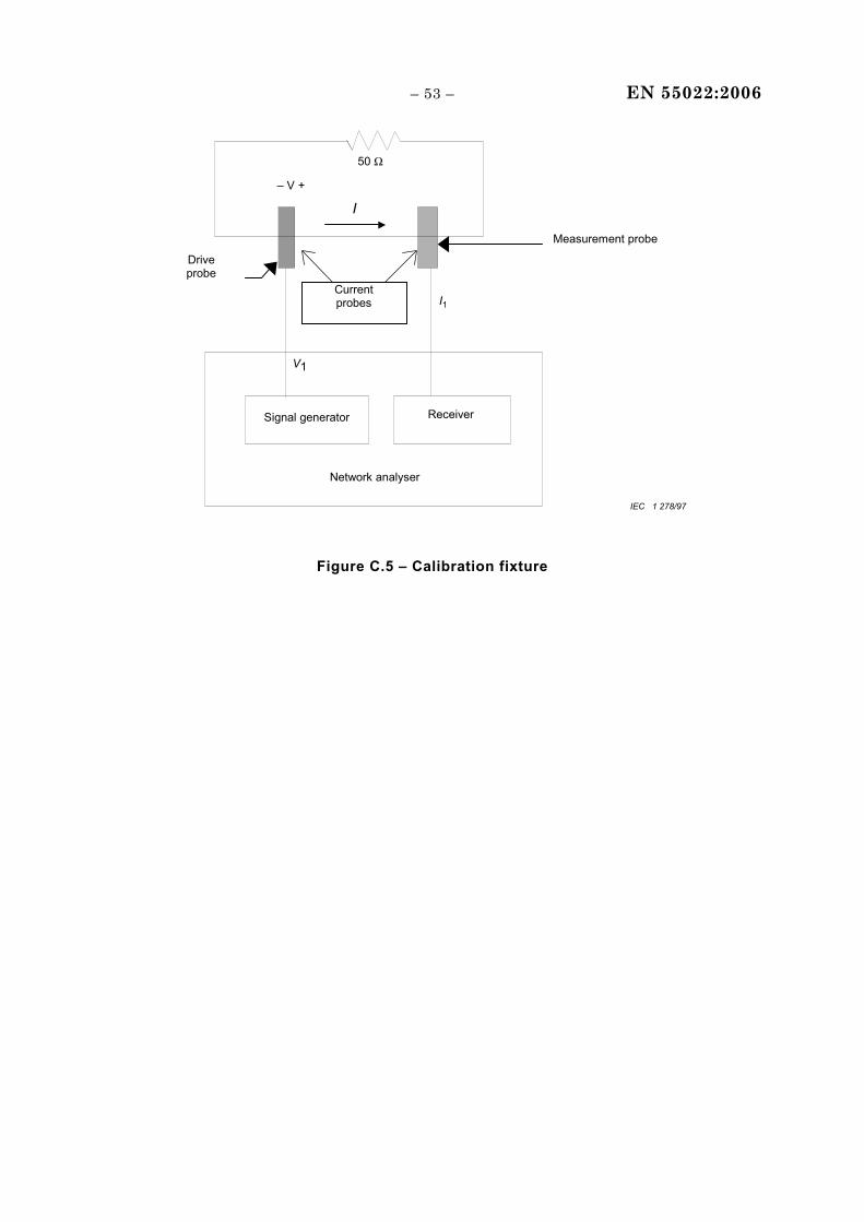
– 53 – EN 55022:2006
50 Ω
Signal generator Receiver
Network analyser
Currentprobes
– V +
I
I1
V1
Driveprobe
Measurement probe
IEC 1 278/97
Figure C.5 – Calibration fixture

EN 55022:2006 – 54 –
Select port type
Is the EUT port atelecommunication port as
defined in clause 3.6 ?
No test required
Use the process for “Other”
port types
Start of process
End of Process
Use methoddefined in C.1.2 tomeasure voltage
or current
Apply voltage orcurrent limits of
Table 3 or 4
Screened orcoaxial
Use methoddefined in
Section 9.3
Apply limits ofTable 1 or 2
MainsUnscreened balanced pairs
Is an ISN available according to 9.6.2 through
which the EUT will operate?
Use method defined in 9.6.3.1and C.1.1 to measure voltage
or use method defined in 9.6.3.2and C.1.1 to measure current
Apply voltage or current limits of Table 3 or 4
For Ports connecting to: -Category 6 cable or better, use ISN
as defined in 9.6.2 c)1) -Category 5 cable or better, use ISN
as defined in 9.6.2 c)2) -Category 3 cable or better, use ISN
as defined in 9.6.2 c)3) -For “poorly” balanced cable, use
ISN as defined in 9.6.2 c)4)
Note The method ofC.1.4 can be used at allfrequencies if desired.
Use method defined in C.1.3 to measure voltage and current
Apply voltage and current limits of Table 3 or 4
Voltage and current Limits
met at all frequencies?
Measure non-compliant frequencies using method
defined in C.1.4
Apply current limits of Table 3 or 4
Other
No
No
Is a CDN as detailed in IEC 61000-4-6
available through which the EUT will
operate? Yes
No
Yes
Apply ferrites to cable Measure the common mode impedance using the method
defined in C.2 and adjust ferrite such that impedance is
150 Ω ± 20 Ω Measure current
C.1.4
Is common mode
impedance toward the AE <150 Ω
Yes
No
No
Does the CDN's LCL exceed the requirements of
9.6.2 for the appropriate cable
category?
Yes
Yes
No
No
Is an ISNavailable according
to Annex D throughwhich the EUT will
operate?
Use methoddefined in C.1.1 tomeasure voltage
or current
Yes
No
Yes
Apply 150 Ω resistorbetween shield and
ground.Apply ferrites to cable
between 150 Ωresistor and AE.
Measure the commonmode impedance towardthe AE using the method
defined in C.2 andensure that theimpedance is
>>150 Ω.
Measure the voltage orcurrent
C.1.2
IEC 1350/04
Figure C.6 – Flowchart for selecting test method
– 55 – EN 55022:2006
Annex D (informative)
Schematic diagrams of examples of impedance
stabilization networks (ISN)
L1
C C
R R
L2 = 2 × 38 mH
EUT AEBalanced pair
Zcat
Rx50 ΩR = 200 Ω
C = 4,7 μF
L1 = 2 × 38 mH
L2
ISN
EUT = Equipment under test
AE = Associated equipment
ISN metal case
Rx = Receiver input IEC 1129/03
NOTE 1 Nominal voltage division factor defined in 9.6.2 e) = 9,5 dB.
NOTE 2 Zcat represents the unbalance network required to adjust the LCL of the ISN to the values specified in 9.6.2 c) 1) – 4).
Figure D.1 − ISN for use with unscreened single balanced pairs
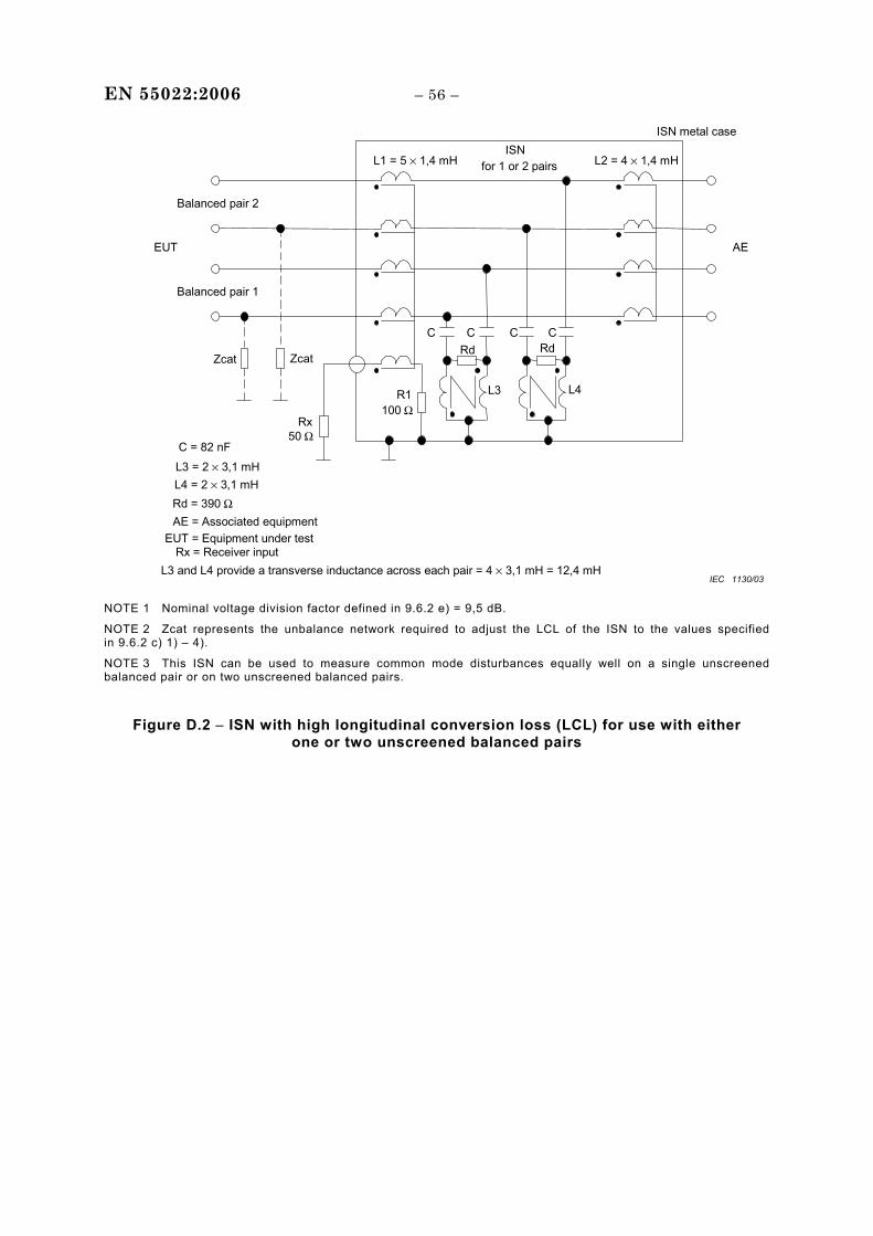
EN 55022:2006 – 56 –
Rx
L1 = 5 × 1,4 mH L2 = 4 × 1,4 mH
C = 82 nF
L3 = 2 × 3,1 mHL4 = 2 × 3,1 mH
Balanced pair 1
Balanced pair 2
EUT AE
L3 and L4 provide a transverse inductance across each pair = 4 × 3,1 mH = 12,4 mH
R1100 Ω
ISN
Zcat
EUT = Equipment under testAE = Associated equipmentRd = 390 Ω
Rx = Receiver input
50 Ω
L4
Rd
L3
RdC
for 1 or 2 pairs
ISN metal case
Zcat
C C C
IEC 1130/03
NOTE 1 Nominal voltage division factor defined in 9.6.2 e) = 9,5 dB.
NOTE 2 Zcat represents the unbalance network required to adjust the LCL of the ISN to the values specified in 9.6.2 c) 1) – 4).
NOTE 3 This ISN can be used to measure common mode disturbances equally well on a single unscreened balanced pair or on two unscreened balanced pairs.
Figure D.2 − ISN with high longitudinal conversion loss (LCL) for use with either one or two unscreened balanced pairs
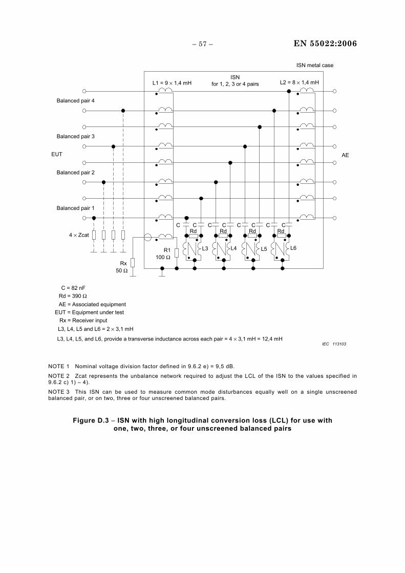
– 57 – EN 55022:2006
Rx
L1 = 9 × 1,4 mH L2 = 8 × 1,4 mH
C = 82 nF
L3, L4, L5 and L6 = 2 × 3,1 mH
Balanced pair 1
Balanced pair 2
EUT AE
L3, L4, L5, and L6, provide a transverse inductance across each pair = 4 × 3,1 mH = 12,4 mH
R1100 Ω
ISN
EUT = Equipment under testAE = Associated equipmentRd = 390 Ω
Rx = Receiver input
50 Ω
L4L3
RdC
Balanced pair 3
Balanced pair 4
L5 L6
4 × Zcat
for 1, 2, 3 or 4 pairs
ISN metal case
C C C C C C CRd Rd Rd
IEC 113103
NOTE 1 Nominal voltage division factor defined in 9.6.2 e) = 9,5 dB.
NOTE 2 Zcat represents the unbalance network required to adjust the LCL of the ISN to the values specified in 9.6.2 c) 1) – 4).
NOTE 3 This ISN can be used to measure common mode disturbances equally well on a single unscreened balanced pair, or on two, three or four unscreened balanced pairs.
Figure D.3 − ISN with high longitudinal conversion loss (LCL) for use with one, two, three, or four unscreened balanced pairs
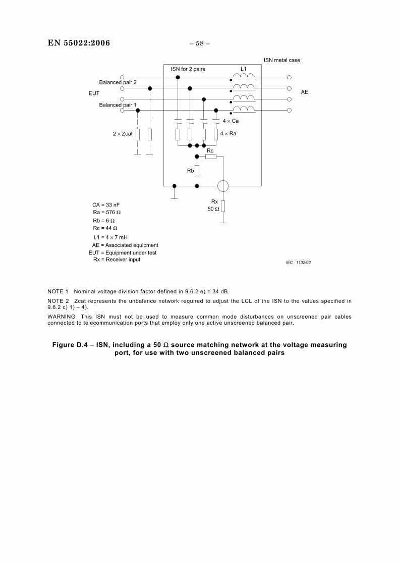
EN 55022:2006 – 58 –
EUT
4 × Ra
4 × Ca
L1
L1 = 4 × 7 mH
Ra = 576 ΩCA = 33 nF
ISN for 2 pairs
50 Ω
Rx = Receiver input
AE
Balanced pair 2
2 × Zcat
EUT = Equipment under testAE = Associated equipment
ISN metal case
Rb
Rc
Rb = 6 ΩRc = 44 Ω
Rx
Balanced pair 1
IEC 1132/03
NOTE 1 Nominal voltage division factor defined in 9.6.2 e) = 34 dB.
NOTE 2 Zcat represents the unbalance network required to adjust the LCL of the ISN to the values specified in 9.6.2 c) 1) – 4).
WARNING This ISN must not be used to measure common mode disturbances on unscreened pair cables connected to telecommunication ports that employ only one active unscreened balanced pair.
Figure D.4 − ISN, including a 50 Ω source matching network at the voltage measuring port, for use with two unscreened balanced pairs
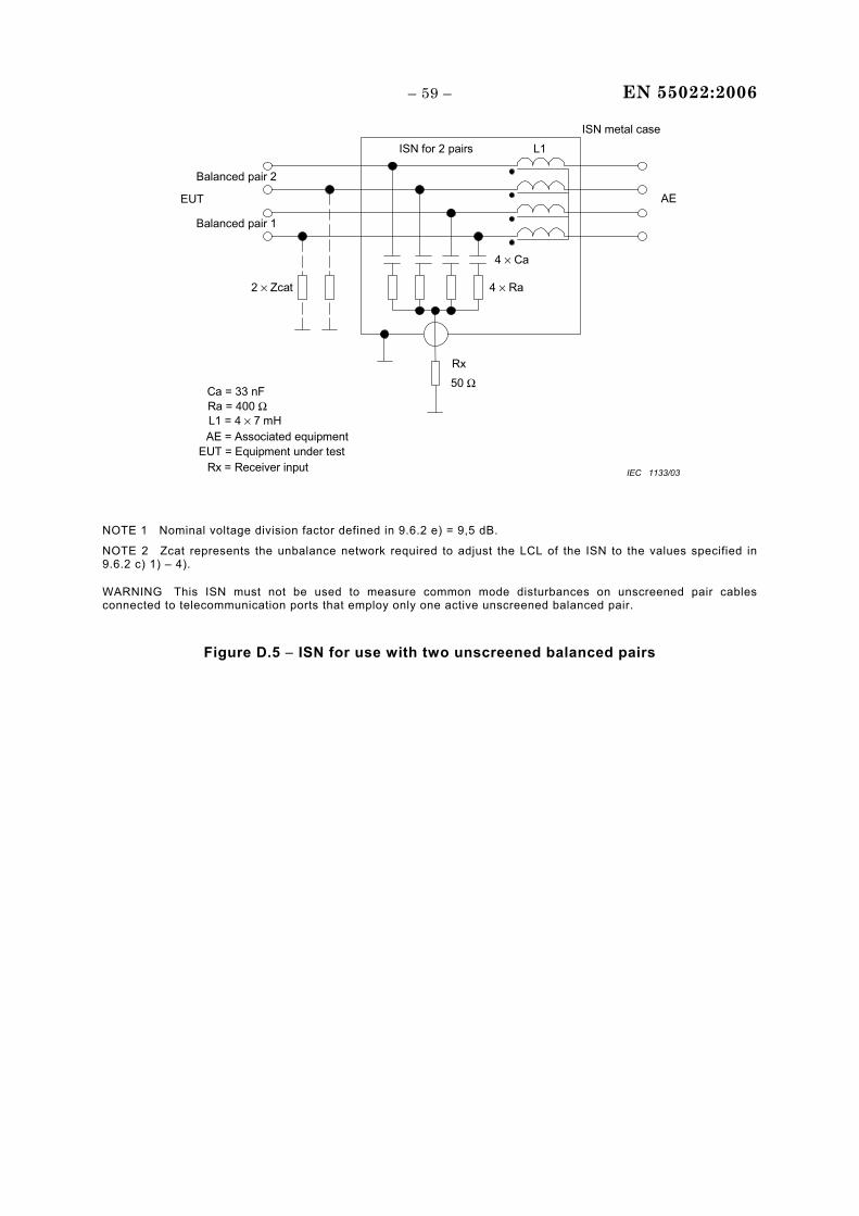
– 59 – EN 55022:2006
EUT
4 × Ra
4 × Ca
L1
L1 = 4 × 7 mHRa = 400 ΩCa = 33 nF
ISN for 2 pairs
50 Ω
AE
Balanced pair 1
Balanced pair 2
2 × Zcat
EUT = Equipment under testAE = Associated equipment
Rx
ISN metal case
Rx = Receiver input IEC 1133/03
NOTE 1 Nominal voltage division factor defined in 9.6.2 e) = 9,5 dB.
NOTE 2 Zcat represents the unbalance network required to adjust the LCL of the ISN to the values specified in 9.6.2 c) 1) – 4).
WARNING This ISN must not be used to measure common mode disturbances on unscreened pair cables connected to telecommunication ports that employ only one active unscreened balanced pair.
Figure D.5 − ISN for use with two unscreened balanced pairs
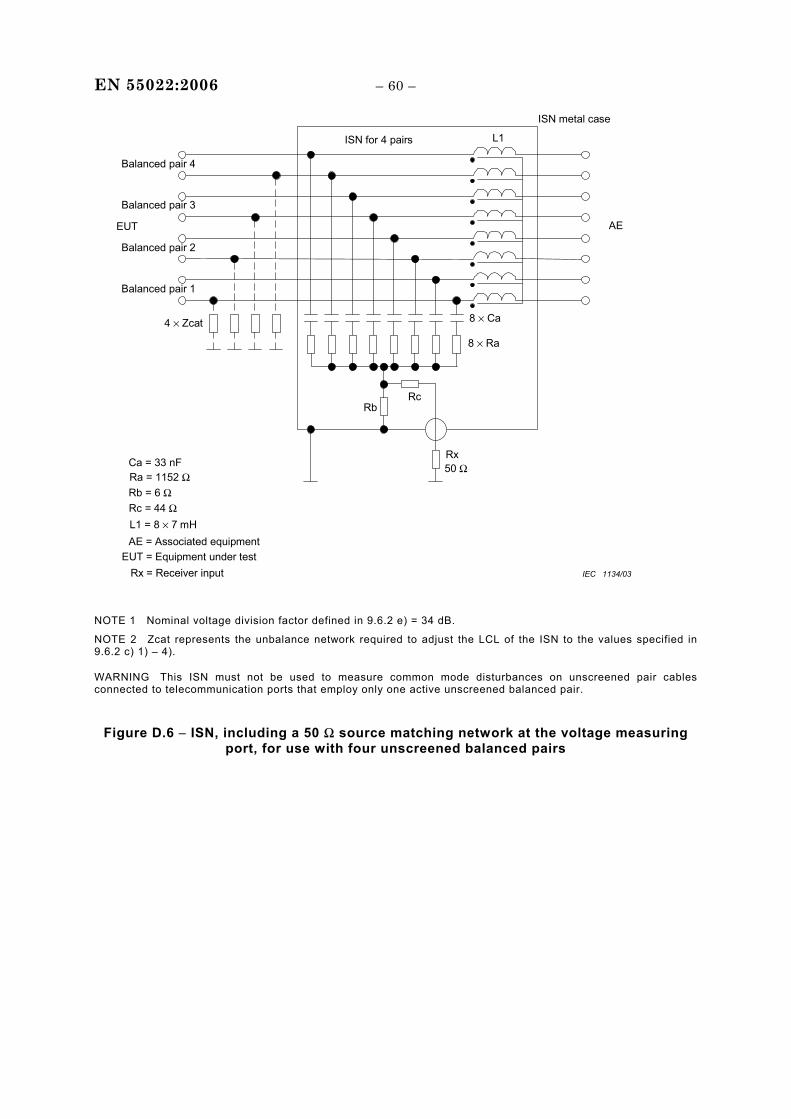
EN 55022:2006 – 60 –
AE
8 × Ra
8 × Ca
L1
Ra = 1152 ΩCa = 33 nF
ISN for 4 pairs
50 ΩRx
L1 = 8 × 7 mH
Balanced pair 1
Balanced pair 2
EUT
Balanced pair 3
Balanced pair 4
4 × Zcat
EUT = Equipment under testAE = Associated equipment
RbRc
Rb = 6 ΩRc = 44 Ω
ISN metal case
Rx = Receiver input IEC 1134/03
NOTE 1 Nominal voltage division factor defined in 9.6.2 e) = 34 dB.
NOTE 2 Zcat represents the unbalance network required to adjust the LCL of the ISN to the values specified in 9.6.2 c) 1) – 4).
WARNING This ISN must not be used to measure common mode disturbances on unscreened pair cables connected to telecommunication ports that employ only one active unscreened balanced pair.
Figure D.6 − ISN, including a 50 Ω source matching network at the voltage measuring port, for use with four unscreened balanced pairs
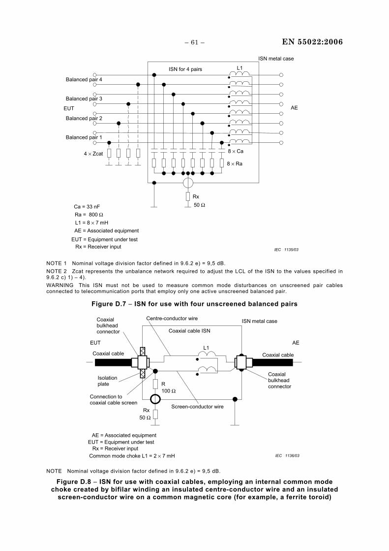
– 61 – EN 55022:2006
AE
8 × Ra
8 × Ca
L1
Ra = 800 ΩCa = 33 nF
ISN for 4 pairs
50 ΩRx
L1 = 8 × 7 mH
Balanced pair 1
Balanced pair 2
EUT
Balanced pair 3
Balanced pair 4
4 × Zcat
EUT = Equipment under test
AE = Associated equipment
ISN metal case
Rx = Receiver input IEC 1135/03 NOTE 1 Nominal voltage division factor defined in 9.6.2 e) = 9,5 dB. NOTE 2 Zcat represents the unbalance network required to adjust the LCL of the ISN to the values specified in 9.6.2 c) 1) – 4). WARNING This ISN must not be used to measure common mode disturbances on unscreened pair cables connected to telecommunication ports that employ only one active unscreened balanced pair.
Figure D.7 − ISN for use with four unscreened balanced pairs
ISN metal case
R
Rx = Receiver input
EUT
100 Ω
Isolationplate
L1
Common mode choke L1 = 2 × 7 mH
50 Ω
AE
Centre-conductor wireCoaxialbulkheadconnector
EUT = Equipment under testAE = Associated equipment
Connection tocoaxial cable screen
Coaxial cable ISN
Coaxial cableCoaxial cable
RxScreen-conductor wire
Coaxialbulkheadconnector
IEC 1136/03 NOTE Nominal voltage division factor defined in 9.6.2 e) = 9,5 dB.
Figure D.8 − ISN for use with coaxial cables, employing an internal common mode choke created by bifilar winding an insulated centre-conductor wire and an insulated
screen-conductor wire on a common magnetic core (for example, a ferrite toroid)
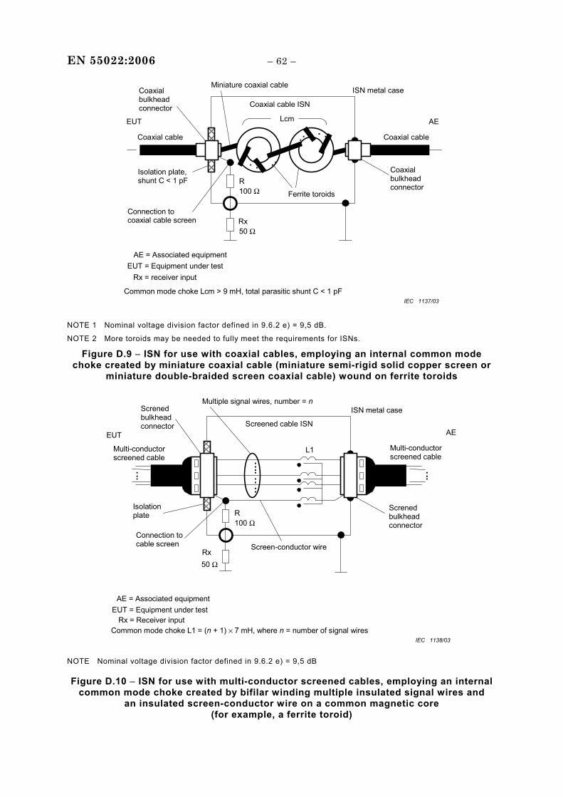
EN 55022:2006 – 62 –
ISN metal case
R
Rx
EUT
100 Ω
Lcm
Common mode choke Lcm > 9 mH, total parasitic shunt C < 1 pF
50 Ω
AE
Miniature coaxial cable
EUT = Equipment under test AE = Associated equipment
Isolation plate, shunt C < 1 pF
Ferrite toroids
. . . .
. . . .
Coaxial cable ISN
Coaxial cable Coaxial cable
Rx = receiver input
Coaxial bulkhead connector
Coaxial bulkhead connector
Connection to coaxial cable screen
IEC 1137/03
NOTE 1 Nominal voltage division factor defined in 9.6.2 e) = 9,5 dB.
NOTE 2 More toroids may be needed to fully meet the requirements for ISNs.
Figure D.9 − ISN for use with coaxial cables, employing an internal common mode choke created by miniature coaxial cable (miniature semi-rigid solid copper screen or
miniature double-braided screen coaxial cable) wound on ferrite toroids
ISN metal case
R
Rx = Receiver input
EUT
100 Ω
L1
Common mode choke L1 = (n + 1) × 7 mH, where n = number of signal wires
50 Ω
AE
Multiple signal wires, number = n
EUT = Equipment under testAE = Associated equipment
Isolationplate
Screened cable ISN
... ...
RxScreen-conductor wire
....
..
..
Multi-conductorscreened cable
Multi-conductorscreened cable
Screnedbulkheadconnector
Screnedbulkheadconnector
Connection tocable screen
IEC 1138/03
NOTE Nominal voltage division factor defined in 9.6.2 e) = 9,5 dB
Figure D.10 − ISN for use with multi-conductor screened cables, employing an internal common mode choke created by bifilar winding multiple insulated signal wires and
an insulated screen-conductor wire on a common magnetic core (for example, a ferrite toroid)
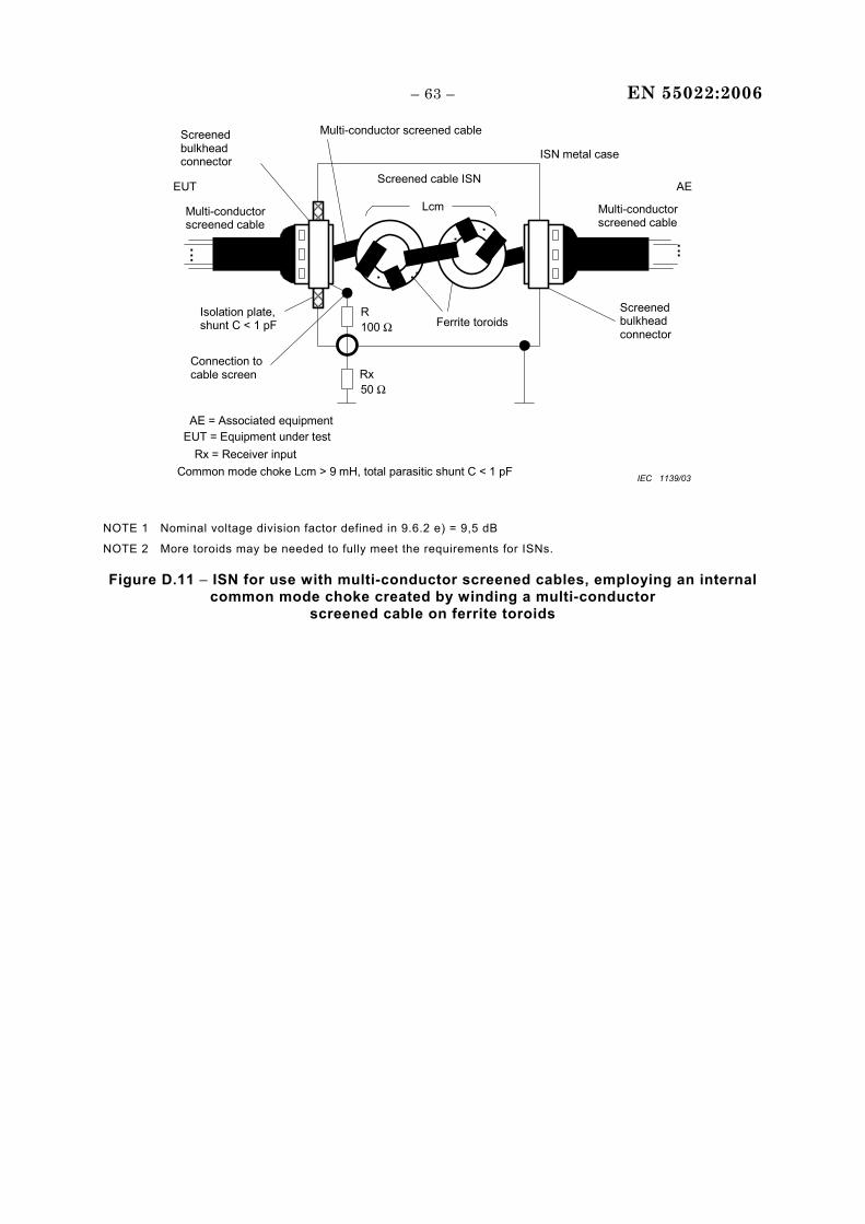
– 63 – EN 55022:2006
ISN metal case
R
Rx
EUT
100 Ω
Lcm
Common mode choke Lcm > 9 mH, total parasitic shunt C < 1 pF
50 Ω
AE
Multi-conductor screened cable
EUT = Equipment under test AE = Associated equipment
Isolation plate, shunt C < 1 pF Ferrite toroids
. . . . . . . .
Connection to cable screen
Screened cable ISN
. . . . . .
Multi-conductor screened cable
Multi-conductor screened cable
Screened bulkhead connector
Screened bulkhead connector
Rx = Receiver input
IEC 1139/03
NOTE 1 Nominal voltage division factor defined in 9.6.2 e) = 9,5 dB
NOTE 2 More toroids may be needed to fully meet the requirements for ISNs.
Figure D.11 − ISN for use with multi-conductor screened cables, employing an internal common mode choke created by winding a multi-conductor
screened cable on ferrite toroids
EN 55022:2006 – 64 –
Annex E (informative)
Parameters of signals at telecommunication ports
E.1 General
No limits are defined for differential current or voltage signal levels in this standard.
However, the maximum signal levels that can be present at telecommunication ports in differential mode are dependent upon, and are limited by, the electrical balance or longitudinal conversion loss (LCL) [1] [2] of the telecommunication ports and the cables or networks to which they are intended to be connected, if the wanted signals are not to appear as unacceptable disturbances across the common mode impedance to ground.
The LCL of a signal port, cable, or network causes a portion of any differential signals on that port, cable, or network to be converted to common mode disturbances for which this standard has defined limits [3] [4] [5]. Common mode disturbances (also called antenna mode disturbances because they are a source of radiated disturbances in the environment) must be limited if interference with the reception of radio signals of all kinds is to be minimized. Common mode disturbances created at a nominally balanced signal port or transmission medium, for example a twisted copper pair, must be controlled and limited whether or not the port or medium is provided with an overall shield. If a shielded medium is used, deficiencies in the shield itself as well as in the shield connectors – leading perhaps to significant electrical discontinuities – will allow a portion of the common mode disturbances created within the shield environment to appear outside the shield.
The worst-case values for balance and LCL quoted in many network specifications are based upon the desired signal transmission and crosstalk performance of the networks and do not necessarily have regard for the control of the common mode disturbances considered in this standard.
To ensure that the physical layer specifications for telecommunication networks do not inadvertently lead to the generation of unacceptable electromagnetic disturbances, it is essential that the electromagnetic compatibility (EMC) implications of the specifications for some critical parameters be considered early in the development of the network standards.
To achieve EMC of telecommunication networks employing twisted pair media, the most important parameters to consider are:
• the levels specified for the wanted transverse or differential mode electrical signals; • the spectral characteristics of the line codes specified for the wanted differential signals; • the design of the protocol of the wanted differential signals; • the expected electrical balance or LCL of the physical copper media, in situ, on which the
wanted electrical signals will be conveyed; • the electrical balance or LCL of the telecommunication signal ports of the medium
attachment units which will be connected to the physical media;
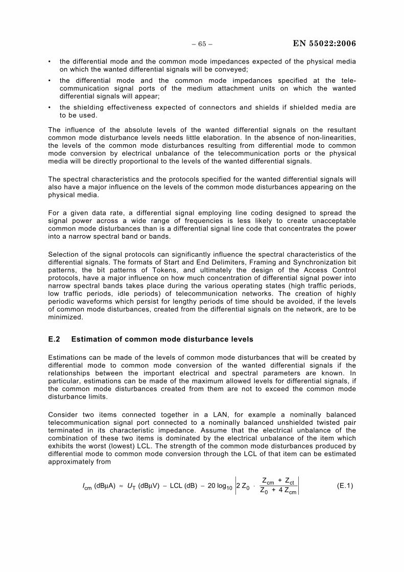
– 65 – EN 55022:2006
• the differential mode and the common mode impedances expected of the physical media on which the wanted differential signals will be conveyed;
• the differential mode and the common mode impedances specified at the tele-communication signal ports of the medium attachment units on which the wanted differential signals will appear;
• the shielding effectiveness expected of connectors and shields if shielded media are to be used.
The influence of the absolute levels of the wanted differential signals on the resultant common mode disturbance levels needs little elaboration. In the absence of non-linearities, the levels of the common mode disturbances resulting from differential mode to common mode conversion by electrical unbalance of the telecommunication ports or the physical media will be directly proportional to the levels of the wanted differential signals.
The spectral characteristics and the protocols specified for the wanted differential signals will also have a major influence on the levels of the common mode disturbances appearing on the physical media.
For a given data rate, a differential signal employing line coding designed to spread the signal power across a wide range of frequencies is less likely to create unacceptable common mode disturbances than is a differential signal line code that concentrates the power into a narrow spectral band or bands.
Selection of the signal protocols can significantly influence the spectral characteristics of the differential signals. The formats of Start and End Delimiters, Framing and Synchronization bit patterns, the bit patterns of Tokens, and ultimately the design of the Access Control protocols, have a major influence on how much concentration of differential signal power into narrow spectral bands takes place during the various operating states (high traffic periods, low traffic periods, idle periods) of telecommunication networks. The creation of highly periodic waveforms which persist for lengthy periods of time should be avoided, if the levels of common mode disturbances, created from the differential signals on the network, are to be minimized.
E.2 Estimation of common mode disturbance levels
Estimations can be made of the levels of common mode disturbances that will be created by differential mode to common mode conversion of the wanted differential signals if the relationships between the important electrical and spectral parameters are known. In particular, estimations can be made of the maximum allowed levels for differential signals, if the common mode disturbances created from them are not to exceed the common mode disturbance limits.
Consider two items connected together in a LAN, for example a nominally balanced telecommunication signal port connected to a nominally balanced unshielded twisted pair terminated in its characteristic impedance. Assume that the electrical unbalance of the combination of these two items is dominated by the electrical unbalance of the item which exhibits the worst (lowest) LCL. The strength of the common mode disturbances produced by differential mode to common mode conversion through the LCL of that item can be estimated approximately from
I Ucm T 10cm ct
0 c (dB A) (dB V) LCL (dB) 20 log 2 Z
+ Z + 4 Zμ μ≈ − − ⋅0
ZZ m
(E.1)
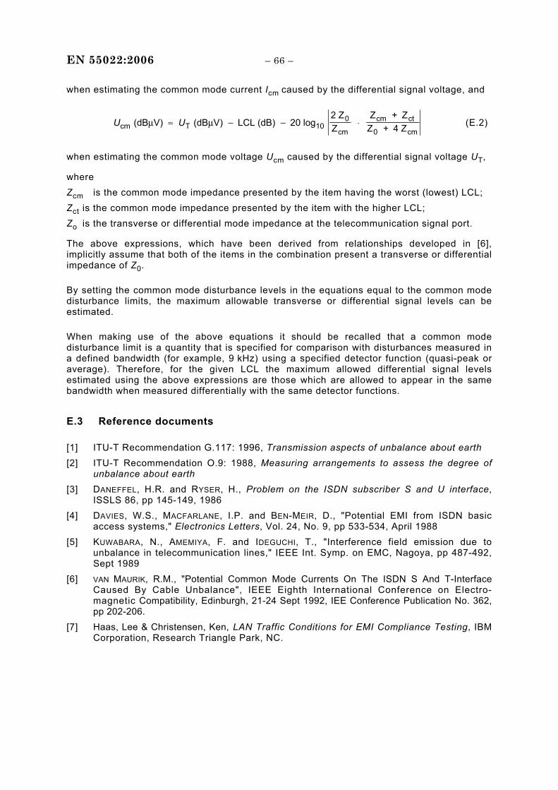
EN 55022:2006 – 66 –
when estimating the common mode current Icm caused by the differential signal voltage, and
U Ucm T 100
cm
cm ct
0 c (dB V) (dB V) LCL (dB) 20 log
2 Z
+ Z + 4 Zμ μ≈ − − ⋅Z
ZZ m
(E.2)
when estimating the common mode voltage Ucm caused by the differential signal voltage UT,
where Zcm is the common mode impedance presented by the item having the worst (lowest) LCL; Zct is the common mode impedance presented by the item with the higher LCL; Zo is the transverse or differential mode impedance at the telecommunication signal port.
The above expressions, which have been derived from relationships developed in [6], implicitly assume that both of the items in the combination present a transverse or differential impedance of Z0.
By setting the common mode disturbance levels in the equations equal to the common mode disturbance limits, the maximum allowable transverse or differential signal levels can be estimated.
When making use of the above equations it should be recalled that a common mode disturbance limit is a quantity that is specified for comparison with disturbances measured in a defined bandwidth (for example, 9 kHz) using a specified detector function (quasi-peak or average). Therefore, for the given LCL the maximum allowed differential signal levels estimated using the above expressions are those which are allowed to appear in the same bandwidth when measured differentially with the same detector functions.
E.3 Reference documents
[1] ITU-T Recommendation G.117: 1996, Transmission aspects of unbalance about earth [2] ITU-T Recommendation O.9: 1988, Measuring arrangements to assess the degree of
unbalance about earth [3] DANEFFEL, H.R. and RYSER, H., Problem on the ISDN subscriber S and U interface,
ISSLS 86, pp 145-149, 1986 [4] DAVIES, W.S., MACFARLANE, I.P. and BEN-MEIR, D., "Potential EMI from ISDN basic
access systems," Electronics Letters, Vol. 24, No. 9, pp 533-534, April 1988 [5] KUWABARA, N., AMEMIYA, F. and IDEGUCHI, T., "Interference field emission due to
unbalance in telecommunication lines," IEEE Int. Symp. on EMC, Nagoya, pp 487-492, Sept 1989
[6] VAN MAURIK, R.M., "Potential Common Mode Currents On The ISDN S And T-Interface Caused By Cable Unbalance", IEEE Eighth International Conference on Electro-magnetic Compatibility, Edinburgh, 21-24 Sept 1992, IEE Conference Publication No. 362, pp 202-206.
[7] Haas, Lee & Christensen, Ken, LAN Traffic Conditions for EMI Compliance Testing, IBM Corporation, Research Triangle Park, NC.
– 67 – EN 55022:2006
Annex F (informative)
Rationale for disturbance measurements and methods
on telecommunications ports
F.1 Limits
The disturbance voltage (or current) limit is defined for a TCM load impedance of 150 Ω (as seen by the EUT at the AE port during the measurement). This standardisation is necessary in order to obtain reproducible measurement results, independent of the undefined TCM impedance at the AE and the EUT.
In general, the TCM impedance seen by the EUT at the AE port is not defined unless a CDN/ISN is used. If the AE is located outside the shielded room, the TCM impedance seen by the EUT at the AE port can be determined by the TCM impedance of the feed through-filter between the measurement set-up and the outside world. A Π-type filter has a low TCM impedance whilst a T-type filter has a high TCM impedance.
CDN/ISNs do not exist for all types of cables used by ITE. It is therefore also necessary to define alternative methods that do not use CDN/ISNs (“Non-invasive” test methods).
Only the cable attached to the EUT port under test is shown in the Figures of Annex C. Normally, there are several other cables (or ports) present at the EUT. At least the connection to the mains terminal is present in most cases. The TCM impedance of these other connections (including a possible ground connection) and the presence or absence of these connections during the test can influence the measurement result significantly, in particular for small EUTs. Therefore the TCM impedance of the non-measured connections have to be defined during the test of small EUTs. It is sufficient to have in addition to the port under test at least 2 additional ports connected to a 150 Ω TCM impedance (normally by using an ISN or CDN with the RF measurement port terminated with 50 Ω) for reducing this influence to a negligible amount.
Coupling devices for nonshielded balanced pairs should also simulate the typical LCL (longitudinal conversion loss) of the lowest cabling category (worst LCL) specified for the telecom port under test. The idea of this requirement is to take into account the transformation of the symmetrical signal into a TCM signal, which might contribute to the radiation when the EUT is used in the real application. Asymmetry in the ISN is purposely constructed to yield the specified LCL. This asymmetry may enhance or cancel the asymmetry of the EUT. In the interest of determining the worst case emissions and optimization of test repeatability, consideration should therefore be given to repeating the testing with the LCL imbalance on each wire of a balanced pair when using the appropriate ISN as defined in 9.6.2.
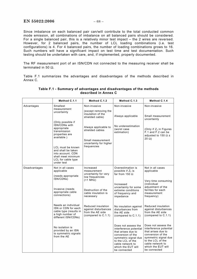
EN 55022:2006 – 68 –
Since imbalance on each balanced pair can/will contribute to the total conducted common mode emission, all combinations of imbalance on all balanced pairs should be considered. For a single balanced pair, this is a relatively minor test impact – the 2 wires are reversed. However, for 2 balanced pairs, the number of LCL loading combinations (i.e. test configurations) is 4. For 4 balanced pairs, the number of loading combinations grows to 16. Such numbers will have a significant impact on test time and test documentation. Such testing should be undertaken with care, and, if implemented, properly documented.
The RF measurement port of an ISN/CDN not connected to the measuring receiver shall be terminated in 50 Ω.
Table F.1 summarizes the advantages and disadvantages of the methods described in Annex C.
Table F.1 - Summary of advantages and disadvantages of the methods described in Annex C
Method C.1.1 Method C.1.2 Method C.1.3 Method C.1.4
Advantages Smallest measurement uncertainty
(Only possible if ISN/CDNs with appropriate transmission properties are available )
LCL must be known and shall be taken into account. CDN shall meet minimum LCL for cable type under test
Non-invasive
(except removing the insulation of the shielded cable)
Always applicable to shielded cables
Small measurement uncertainty for higher frequencies
Non-invasive
Always applicable
No underestimation (worst case estimation)
Non-invasive
Small measurement uncertainty
(Only if Z2 in Figures F.1 and F.2 can be adjusted to 150 Ω ± 20 Ω)
Disadvantages Not in all cases applicable
(needs appropriate ISN/CDNs)
Invasive (needs appropriate cable connections)
Needs an individual ISN or CDN for each cable type (results in a high number of different ISN/CDNs)
No isolation is provided by an ISN to symmetric signals from the AE
Increased measurement uncertainty for very low frequencies (<1 MHz)
Destruction of the cable insulation is necessary
Reduced insulation against disturbances from the AE side (compared to C.1.1)
Overestimation is possible if Z2 is far from 150 Ω
Increased uncertainty for some extreme conditions of frequency and impedance
No insulation against disturbances from the AE side (compared to C.1.1)
Does not assess the interference potential that arises due to conversion of the symmetric signal due to the LCL of the cable network to which the EUT will be connected
Not in all cases applicable
Very time consuming (individual adjustment of the ferrites for each measurement frequency)
Reduced insulation against disturbances from the AE side (compared to C.1.1)
Does not assess the interference potential that arises due to conversion of the symmetric signal due to the LCL of the cable network to which the EUT will be connected
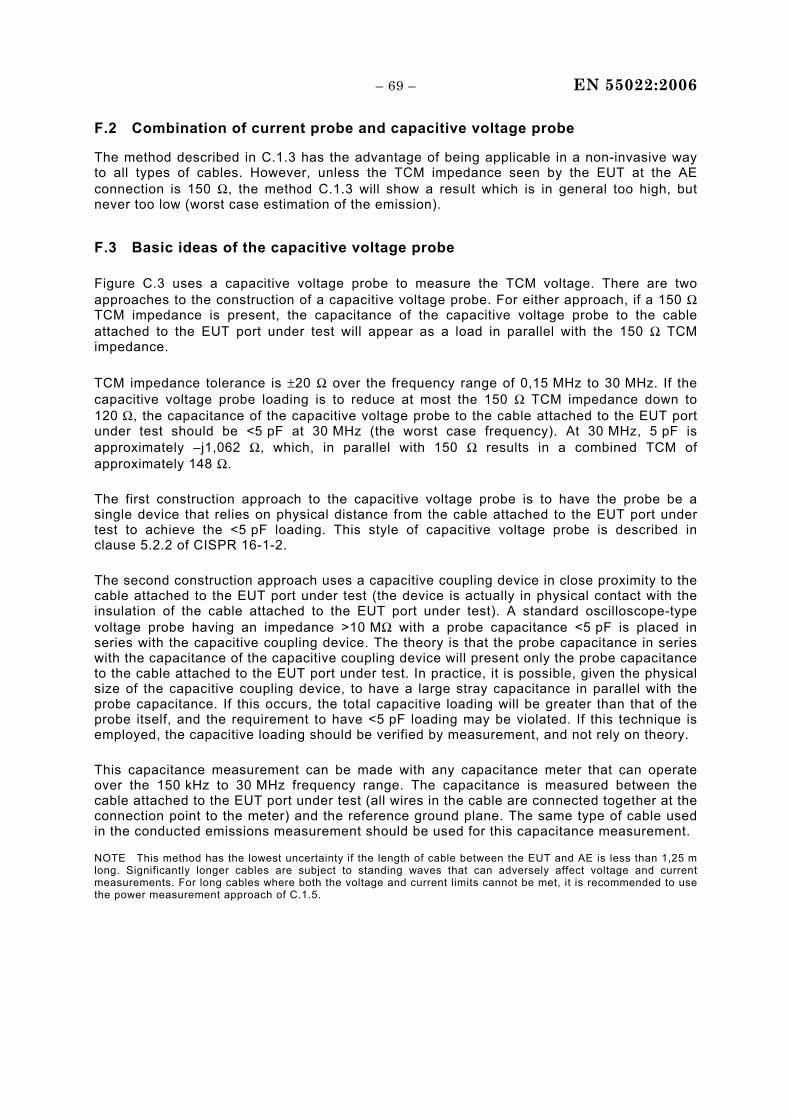
– 69 – EN 55022:2006
F.2 Combination of current probe and capacitive voltage probe
The method described in C.1.3 has the advantage of being applicable in a non-invasive way to all types of cables. However, unless the TCM impedance seen by the EUT at the AE connection is 150 Ω, the method C.1.3 will show a result which is in general too high, but never too low (worst case estimation of the emission).
F.3 Basic ideas of the capacitive voltage probe
Figure C.3 uses a capacitive voltage probe to measure the TCM voltage. There are two approaches to the construction of a capacitive voltage probe. For either approach, if a 150 Ω TCM impedance is present, the capacitance of the capacitive voltage probe to the cable attached to the EUT port under test will appear as a load in parallel with the 150 Ω TCM impedance.
TCM impedance tolerance is ±20 Ω over the frequency range of 0,15 MHz to 30 MHz. If the capacitive voltage probe loading is to reduce at most the 150 Ω TCM impedance down to 120 Ω, the capacitance of the capacitive voltage probe to the cable attached to the EUT port under test should be <5 pF at 30 MHz (the worst case frequency). At 30 MHz, 5 pF is approximately –j1,062 Ω, which, in parallel with 150 Ω results in a combined TCM of approximately 148 Ω.
The first construction approach to the capacitive voltage probe is to have the probe be a single device that relies on physical distance from the cable attached to the EUT port under test to achieve the <5 pF loading. This style of capacitive voltage probe is described in clause 5.2.2 of CISPR 16-1-2.
The second construction approach uses a capacitive coupling device in close proximity to the cable attached to the EUT port under test (the device is actually in physical contact with the insulation of the cable attached to the EUT port under test). A standard oscilloscope-type voltage probe having an impedance >10 MΩ with a probe capacitance <5 pF is placed in series with the capacitive coupling device. The theory is that the probe capacitance in series with the capacitance of the capacitive coupling device will present only the probe capacitance to the cable attached to the EUT port under test. In practice, it is possible, given the physical size of the capacitive coupling device, to have a large stray capacitance in parallel with the probe capacitance. If this occurs, the total capacitive loading will be greater than that of the probe itself, and the requirement to have <5 pF loading may be violated. If this technique is employed, the capacitive loading should be verified by measurement, and not rely on theory.
This capacitance measurement can be made with any capacitance meter that can operate over the 150 kHz to 30 MHz frequency range. The capacitance is measured between the cable attached to the EUT port under test (all wires in the cable are connected together at the connection point to the meter) and the reference ground plane. The same type of cable used in the conducted emissions measurement should be used for this capacitance measurement.
NOTE This method has the lowest uncertainty if the length of cable between the EUT and AE is less than 1,25 m long. Significantly longer cables are subject to standing waves that can adversely affect voltage and current measurements. For long cables where both the voltage and current limits cannot be met, it is recommended to use the power measurement approach of C.1.5.
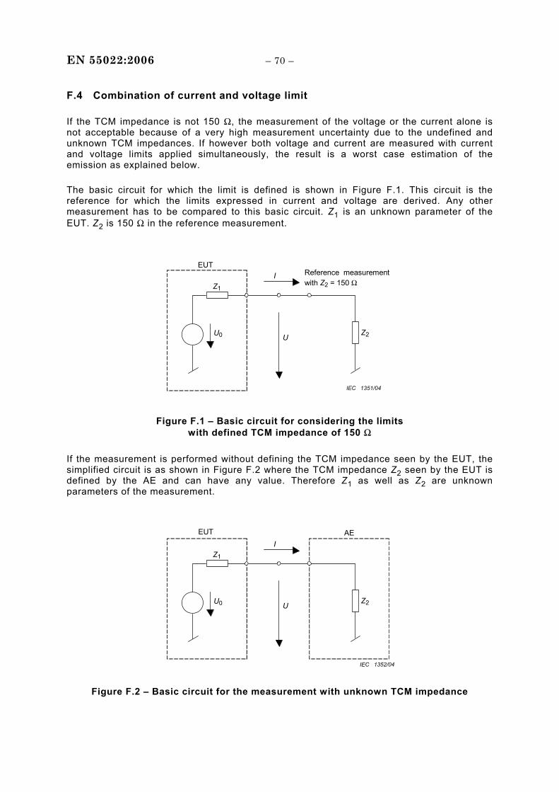
EN 55022:2006 – 70 –
F.4 Combination of current and voltage limit
If the TCM impedance is not 150 Ω, the measurement of the voltage or the current alone is not acceptable because of a very high measurement uncertainty due to the undefined and unknown TCM impedances. If however both voltage and current are measured with current and voltage limits applied simultaneously, the result is a worst case estimation of the emission as explained below.
The basic circuit for which the limit is defined is shown in Figure F.1. This circuit is the reference for which the limits expressed in current and voltage are derived. Any other measurement has to be compared to this basic circuit. Z1 is an unknown parameter of the EUT. Z2 is 150 Ω in the reference measurement.
Z1
Z2 U
I
U0
EUT Reference measurement with Z2 = 150 Ω
IEC 1351/04
Figure F.1 – Basic circuit for considering the limits
with defined TCM impedance of 150 Ω If the measurement is performed without defining the TCM impedance seen by the EUT, the simplified circuit is as shown in Figure F.2 where the TCM impedance Z2 seen by the EUT is defined by the AE and can have any value. Therefore Z1 as well as Z2 are unknown parameters of the measurement.
Z1
Z2 U
I
U0
EUT AE
IEC 1352/04
Figure F.2 – Basic circuit for the measurement with unknown TCM impedance
– 71 – EN 55022:2006
If the measurement is performed according to the circuit of Figure F.1, the limit of current and the limit of voltage are equivalent. The relation between current and voltage will always be 150 Ω and either of the two can be used to determine the compliance with the limit. This is not the case if Z2 is not 150 Ω (see Figure F.2).
It is important to be aware that the quantity determining the compliance with the limit is not the source voltage U0. The interference voltage measured has to be measured at a standardized Z2 of 150 Ω and depends on Z1 Z2 and U0 together. The limit value can be reached with an EUT containing a high impedance Z1 and a high source voltage U0, or with a lower U0 combined with a lower impedance Z1.
In the more general case of Figure F.2 where Z2 is not defined, it is not possible to measure the exact value of the interference voltage. Since Z1 and U0 are not known, it is not possible to derive the interference voltage, even if the value of Z2 is known (or is measured or calculated from I and U). If for example an EUT with emissions above the limit is measured only by measuring the voltage in a test set-up with low Z2 (Z2 < 150 Ω) at the AE side, the EUT might still seem to comply with the limits. By contrast, if the same EUT is measured only by measuring the current in a test setup with high Z2, (for example by adding ferrites) the EUT might again seem to comply with the limits.
However, it can be shown that, if the current limit and the voltage limit are applied simultaneously, an EUT with emissions exceeding the limits will always be discovered by exceeding either the current limit (if Z2 is <150 Ω) or the voltage limit (if Z2 is >150 Ω).
If the TCM impedance of the AE (Z2) is far from 150 Ω, it is possible that an EUT, which would comply with the limits if measured with Z2 =150 Ω, may be rejected. However it will never happen that an EUT not complying with the limits is accepted. The measurement according to C.1.3 is therefore a worst case estimation of the emission. If an EUT exceeds the limit with this method, it is possible the EUT would comply with the limits if it could be measured with Z2 = 150 Ω. If the EUT measured by this method were compared to a power limit derived from the voltage and current limits, a more accurate measure of the interference potential into 150 Ω is possible. Conducted power measurement techniques are under consideration in CISPR I.
F.5 Adjusting the TCM impedance with ferrites
In some cases (if the TCM impedance at the AE side is originally lower than 150 Ω), it is possible to adjust the impedance by adding ferrites on the cable attached to the EUT port under test. Subclause C.1.4 requires measurement of the TCM impedance and adjustment of the ferrites at each frequency to be measured until the TCM impedance is 150 Ω ± 20 Ω. The method is therefore very complicated and time-consuming if applied to the full frequency spectrum. If the TCM impedance at the AE side is originally higher than 150 Ω, there is no way to adjust the impedance to 150 Ω by adding ferrites or shifting the position of the ferrites for frequencies below 30 MHz. (Other methods to adjust the TCM impedance for specific frequencies could be invented instead).

EN 55022:2006 – 72 –
F.6 Ferrite requirements for use in Annex C
Subclause C.1.2 defines a test setup for measuring the common mode conducted emissions on the shield of a coaxial cable. A 150 Ω load is specified to be connected between the coax shield and the reference ground plane as shown in Figure C.2. Ferrites are shown placed over the coax shield between the 150 Ω load and the AE. Following are functional requirements of the ferrites necessary to satisfy the requirements of C.1.2.
Zeuctcm
Veuctcm 150 Ω (shield to ground)
Zferrite Zaecm
Vaecm
EUT AE Coaxial cable shield
IEC 1353/04 Key
Veutcm common mode voltage generated by the EUT
Zeutcm common mode source impedance of the EUT
Vaecm common mode voltage generated by the AE
Zaecm common mode source impedance of the AE
Zferrite impedance of the ferrites
Z combined impedance of the 150 Ω, Zferrite, and Zaecm
Figure F.3 – Impedance layout of the components used in Figure C.2
Figure F.3 shows all of the basic impedances involved in Figure C.2. The ferrites are specified in C.1.2 to provide a high impedance such that “…the common mode impedance towards the right of the 150 Ω resistor shall be sufficiently large as to not affect the measurement.” This impedance is shown in Figure F.3 as “Z”.
The above quote from C.1.2 infers that the combined series impedance of Zferrite and Zaecm should not load down the 150 Ω resistor. The general approach in CISPR 22 for tolerance on 150 Ω common mode loads is ±20 Ω over the frequency range of 0,15 MHz to 30 MHz. Combining these two concepts, the combined series impedance of Zferrite and Zaecm in parallel with the 150 Ω resistor (Z in Figure F.3) should be no lower than 130 Ω. This in turn implies that this relationship must hold regardless of the value of Zaecm.
To establish the impedance characteristics of the ferrites, only two cases need to be considered: Zaecm = open circuit and Zaecm = short circuit. If the ferrites can be selected to satisfy these requirements, any value of Zaecm will be acceptable.
• Case 1: Zaecm = open circuit
The combined series impedance of Zferrite and Zaecm is also an open circuit. An open circuit in parallel with the 150 Ω load is 150 Ω. Zferrite can be of any value.
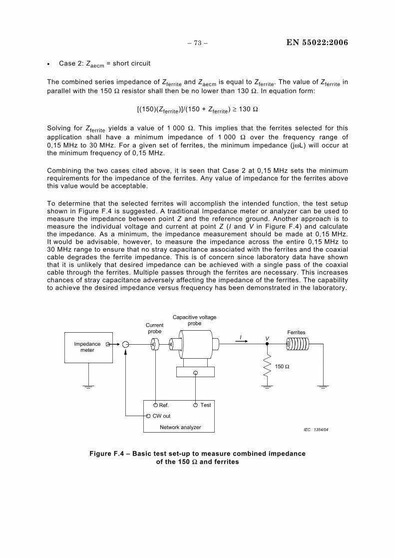
– 73 – EN 55022:2006
• Case 2: Zaecm = short circuit
The combined series impedance of Zferrite and Zaecm is equal to Zferrite. The value of Zferrite in parallel with the 150 Ω resistor shall then be no lower than 130 Ω. In equation form:
[(150)(Zferrite)]/(150 + Zferrite) ≥ 130 Ω
Solving for Zferrite yields a value of 1 000 Ω. This implies that the ferrites selected for this application shall have a minimum impedance of 1 000 Ω over the frequency range of 0,15 MHz to 30 MHz. For a given set of ferrites, the minimum impedance (jωL) will occur at the minimum frequency of 0,15 MHz.
Combining the two cases cited above, it is seen that Case 2 at 0,15 MHz sets the minimum requirements for the impedance of the ferrites. Any value of impedance for the ferrites above this value would be acceptable.
To determine that the selected ferrites will accomplish the intended function, the test setup shown in Figure F.4 is suggested. A traditional Impedance meter or analyzer can be used to measure the impedance between point Z and the reference ground. Another approach is to measure the individual voltage and current at point Z (I and V in Figure F.4) and calculate the impedance. As a minimum, the impedance measurement should be made at 0,15 MHz. It would be advisable, however, to measure the impedance across the entire 0,15 MHz to 30 MHz range to ensure that no stray capacitance associated with the ferrites and the coaxial cable degrades the ferrite impedance. This is of concern since laboratory data have shown that it is unlikely that desired impedance can be achieved with a single pass of the coaxial cable through the ferrites. Multiple passes through the ferrites are necessary. This increases chances of stray capacitance adversely affecting the impedance of the ferrites. The capability to achieve the desired impedance versus frequency has been demonstrated in the laboratory.
Impedance meter
Current probe
Capacitive voltage probe
Ferrites VI
Ref. Test
CW out
Network analyzer
150 Ω
IEC 1354/04
Figure F.4 – Basic test set-up to measure combined impedance of the 150 Ω and ferrites
EN 55022:2006 – 74 –
Bibliography
CISPR 16-2 (all parts), Specification for radio disturbance and immunity measuring apparatus and methods – Part 2: Methods of measurement of disturbances and immunity
CISPR 16-3, Specification for radio disturbance and immunity measuring apparatus and methods – Part 3: CISPR technical reports
IEEE Standard 1284-1, IEEE Standard for Information Technology & Transport Independent Printer/System Interface (TIP/SI)
IEEE Standard 1394, IEEE Standard for a High Performance Serial Bus – Firewire
ISO/IEC 11801, Information technology – Generic cabling for customer premises
______________
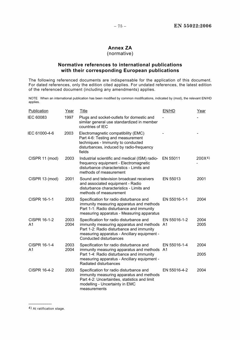
– 75 – EN 55022:2006
Annex ZA (normative)
Normative references to international publications
with their corresponding European publications The following referenced documents are indispensable for the application of this document. For dated references, only the edition cited applies. For undated references, the latest edition of the referenced document (including any amendments) applies. NOTE When an international publication has been modified by common modifications, indicated by (mod), the relevant EN/HD applies. Publication Year Title EN/HD Year
IEC 60083 1997 Plugs and socket-outlets for domestic and similar general use standardized in member countries of IEC
- -
IEC 61000-4-6 2003 Electromagnetic compatibility (EMC) Part 4-6: Testing and measurement techniques - Immunity to conducted disturbances, induced by radio-frequency fields
- -
CISPR 11 (mod) 2003 Industrial scientific and medical (ISM) radio-frequency equipment - Electromagnetic disturbance characteristics - Limits and methods of measurement
EN 55011 200X4)
-
CISPR 13 (mod) 2001 Sound and television broadcast receivers and associated equipment - Radio disturbance characteristics - Limits and methods of measurement
EN 55013 2001
CISPR 16-1-1 2003 Specification for radio disturbance and immunity measuring apparatus and methods Part 1-1: Radio disturbance and immunity measuring apparatus - Measuring apparatus
EN 55016-1-1 2004
CISPR 16-1-2 A1
2003 2004
Specification for radio disturbance and immunity measuring apparatus and methods Part 1-2: Radio disturbance and immunity measuring apparatus - Ancillary equipment - Conducted disturbances
EN 55016-1-2 A1
2004 2005
CISPR 16-1-4 A1
2003 2004
Specification for radio disturbance and immunity measuring apparatus and methods Part 1-4: Radio disturbance and immunity measuring apparatus - Ancillary equipment - Radiated disturbances
EN 55016-1-4 A1
2004 2005
CISPR 16-4-2 2003 Specification for radio disturbance and immunity measuring apparatus and methods Part 4-2: Uncertainties, statistics and limit modelling - Uncertainty in EMC measurements
EN 55016-4-2 2004
___________ 4) At ratification stage.

EN 55022:2006 – 76 –
Annex ZZ (informative)
Coverage of Essential Requirements of EC Directives
This European Standard has been prepared under a mandate given to CENELEC by the European Commission and the European Free Trade Association and within its scope the standard covers essential requirements as given in Article 4(a) of the EC Directive 89/336/EC and Annex I Article 1(a) of the EC Directive 2004/108/EC, and essential requirements of Article 3.1(b) (emission only) of the EC Directive 1999/5/EC.
Compliance with this standard provides one means of conformity with the specified essential requirements of the Directives concerned.
WARNING: Other requirements and other EC Directives may be applicable to the products falling within the scope of this standard.
______________