Embed Size (px)
Citation preview

Certification Requirements for Battery System Compliance to IEEE 1725
April 2013
Revision 2.5
CTIA Certification Program
CTIA Certification Program
1400 16th
Street, NW, Suite 600
Washington, DC 20036
E-mail: [email protected]
Telephone: 1.202.785.0081
www.ctia.org/certification
© 2006 CTIA – The Wireless Association®. All rights reserved.
CTIA hereby grants to CTIA Authorized Testing Laboratories (CATLs), and only to CATLs, a limited, non-transferable license to use
this Test Plan for the sole purpose of testing devices for the CTIA Certification Program, and to reproduce this Test Plan for internal use
only. Any other use of this Test Plan must be authorized in writing by CTIA.
Any reproduction or transmission of all or part of this Test Plan, in any form or by any means, electronic or mechanical, including
photocopying, recording, or via any information storage and retrieval system, without the prior written permission of CTIA, is
unauthorized and strictly prohibited.
Any reproduction of this Test Plan shall display the notice: “Copyright by CTIA. All rights reserved.”

April 2013 i Revision 2.5
TABLE OF CONTENTS
SECTION 1 INTRODUCTION............................................................................................. 1
1.1 PURPOSE ............................................................................................................................................................................ 1
1.2 SCOPE ................................................................................................................................................................................ 1
1.3 APPLICABLE DOCUMENTS ..................................................................................................................................................... 1
1.4 ACRONYMS AND DEFINITIONS ............................................................................................................................................... 2
SECTION 2 VALIDATION PROCESS ............................................................................... 3
SECTION 3 SYSTEM INTEGRATION VALIDATION ................................................... 4
3.1 SYSTEM INTEGRATION CONSIDERATIONS ............................................................................................................................... 4
3.2 AC SUBSYSTEM REQUIREMENTS .......................................................................................................................................... 4
3.3 DC SUBSYSTEM REQUIREMENTS .......................................................................................................................................... 5
3.4 SUBSYSTEM REQUIREMENTS, TRANSPORT OF DANGEROUS GOODS, BATTERY PACK ............................................................... 5
3.5 SUBSYSTEM REQUIREMENTS, TRANSPORT OF DANGEROUS GOODS, CELL .............................................................................. 5
3.6 SUBSYSTEM REQUIREMENTS, DESTINATION COUNTRY ........................................................................................................... 5
3.7 SUBSYSTEM REQUIREMENTS, UL 1642 ................................................................................................................................. 6
SECTION 4 CELL VALIDATION ....................................................................................... 7
4.1 STABILITY ........................................................................................................................................................................... 7
4.2 ISOLATION PROPERTIES ....................................................................................................................................................... 7
4.3 STRENGTH AND PHYSICAL INTEGRITY .................................................................................................................................... 7
4.4 SHRINKAGE ALLOWANCE, AMBIENT TEMPERATURE ................................................................................................................ 8
4.5 SHRINKAGE ALLOWANCE, ELEVATED TEMPERATURE .............................................................................................................. 8
4.6 SHRINKAGE ALLOWANCE ...................................................................................................................................................... 8
4.7 ELECTRODE DESIGN CRITERIA.............................................................................................................................................. 8
4.8 ELECTRODE CAPACITY BALANCE .......................................................................................................................................... 9
4.9 ELECTRODE GEOMETRY ....................................................................................................................................................... 9
4.10 ELECTRODE GEOMETRY ................................................................................................................................................. 9
4.11 ELECTRODE TABS (CONNECTION TO CELL TERMINALS) ...................................................................................................... 9
4.12 APPLICATION OF INSULATION ......................................................................................................................................... 10
4.13 APPLICATION OF INSULATION ......................................................................................................................................... 10
4.14 APPLICATION OF SUPPLEMENTARY INSULATION .............................................................................................................. 10
4.15 INSULATION CHARACTERISTICS ..................................................................................................................................... 11
4.16 CELL VENT MECHANISM ................................................................................................................................................ 11
4.17 RETENTION OF CELL CONTENTS AND PROJECTILE TESTING ............................................................................................. 11
4.18 OVERCURRENT PROTECTION DEVICE ............................................................................................................................. 12
4.19 MAXIMUM RECOMMENDED VOLTAGE .............................................................................................................................. 12
4.20 MATERIALS SPECIFICATIONS ......................................................................................................................................... 12
4.21 CLEANLINESS OF MANUFACTURING OPERATIONS ............................................................................................................ 12
4.22 MANUFACTURING TRACEABILITY .................................................................................................................................... 13

April 2013 ii Revision 2.5
4.23 UNIFORM COATING OF ACTIVE MATERIALS ..................................................................................................................... 13
4.24 BURR CONTROL ........................................................................................................................................................... 13
4.25 BURR CONTROL ........................................................................................................................................................... 14
4.26 PREVENTION OF DAMAGE TO ELECTRODES .................................................................................................................... 14
4.27 CHARACTERISTICS OF MANUFACTURING EQUIPMENT ...................................................................................................... 15
4.28 DEFECTIVE ELECTRODES .............................................................................................................................................. 15
4.29 PREVENTIVE MAINTENANCE PLAN .................................................................................................................................. 15
4.30 TENSION AND DAMAGE ................................................................................................................................................. 15
4.31 COLLECTION OF LOOSE MATERIAL ................................................................................................................................. 16
4.32 DETECTION OF DAMAGED CORES .................................................................................................................................. 16
4.33 CONTROL OF ELECTRODE SPACING ............................................................................................................................... 16
4.34 UNIFORMITY OF INTERNAL ELECTRODE PRESSURE ......................................................................................................... 16
4.35 AVOIDANCE OF CONTAMINANTS ..................................................................................................................................... 17
4.36 INTERNAL SHORT AVOIDANCE ....................................................................................................................................... 17
4.37 INTERNAL SHORT AVOIDANCE ....................................................................................................................................... 17
4.38 TAB POSITIONING ......................................................................................................................................................... 18
4.39 TAB POSITIONING ......................................................................................................................................................... 18
4.40 INTEGRITY OF CELL CORE ASSEMBLY ............................................................................................................................ 18
4.41 POSITIONING OF INSULATING MATERIAL ......................................................................................................................... 18
4.42 POSITIONING OF INSULATING PLATE ............................................................................................................................... 19
4.43 ELECTRODE ALIGNMENT ............................................................................................................................................... 19
4.44 CELL AGING AND VALIDATION OF AGING PROCESS.......................................................................................................... 19
4.45 CELL LEAKAGE ............................................................................................................................................................. 20
4.46 CARE DURING CELL ASSEMBLY ..................................................................................................................................... 20
4.47 QUALIFICATION OF NEW CELL DESIGNS ......................................................................................................................... 20
4.48 QUALIFICATION OF PRODUCTION CELLS ......................................................................................................................... 20
4.49 CELL TRANSPORTATION REGULATIONS .......................................................................................................................... 21
4.50 CELL THERMAL TEST .................................................................................................................................................... 21
4.51 CELL THERMAL TEST .................................................................................................................................................... 21
4.52 EVALUATION OF EXCESS LITHIUM PLATING AND SHORT-CIRCUIT TEST ON CYCLED CELLS ................................................. 21
4.53 EXTERNAL SHORTING OF CELL TERMINALS .................................................................................................................... 22
SECTION 5 BATTERY PACK VALIDATION ................................................................ 26
5.1 TRACEABILITY ................................................................................................................................................................... 26
5.2 PART NUMBER .................................................................................................................................................................. 26
5.3 VOLTAGE .......................................................................................................................................................................... 26
5.4 CHEMISTRY ....................................................................................................................................................................... 26
5.5 PACK VENDOR IDENTIFICATION ........................................................................................................................................... 27
5.6 CIRCUIT LAYOUT ................................................................................................................................................................ 27
5.7 CELL POLARITY ................................................................................................................................................................. 27
5.8 AMBIENT THERMAL CONSIDERATION ................................................................................................................................... 27
5.9 COMPONENT SPECIFICATIONS ............................................................................................................................................ 28
5.10 THERMAL CONSIDERATION ............................................................................................................................................ 28
April 2013 iii Revision 2.5
5.11 LIMIT OUTPUT CURRENT ............................................................................................................................................... 28
5.12 PACK MECHANISMS ...................................................................................................................................................... 29
5.13 THERMAL PROTECTION ................................................................................................................................................. 29
5.14 THERMAL SENSOR DESIGN ........................................................................................................................................... 29
5.15 ACTION, THERMAL PROTECTION .................................................................................................................................... 30
5.16 CHARGING SPECIFICATIONS .......................................................................................................................................... 30
5.17 CHARGE CONSIDERATIONS ........................................................................................................................................... 30
5.18 CHARGER DESIGN ........................................................................................................................................................ 30
5.19 PROTECTION ................................................................................................................................................................ 31
5.20 PROTECTION ................................................................................................................................................................ 31
5.21 SPECIFICATION ............................................................................................................................................................. 31
5.22 PACK OVERCURRENT PROTECTION REQUIREMENT ......................................................................................................... 31
5.23 EXTERNAL MECHANICAL FORCE .................................................................................................................................... 32
5.24 CELL DIMENSIONAL ALLOWANCE ................................................................................................................................... 32
5.25 ELECTRICAL CELL CONNECTIONS .................................................................................................................................. 32
5.26 CELL VENT .................................................................................................................................................................. 32
5.27 HOST REQUIREMENT .................................................................................................................................................... 32
5.28 ESD ............................................................................................................................................................................ 33
5.29 WELDING ..................................................................................................................................................................... 33
5.30 CELL SHORTS .............................................................................................................................................................. 33
5.31 FOREIGN OBJECTS ....................................................................................................................................................... 33
5.32 SOLDERING PROCESS .................................................................................................................................................. 34
5.33 REWORKED CELLS ....................................................................................................................................................... 34
5.34 CIRCUIT CARE .............................................................................................................................................................. 34
5.35 PACK COMPONENT CARE .............................................................................................................................................. 35
5.36 WELDING CARE ............................................................................................................................................................ 35
5.37 ESD ............................................................................................................................................................................ 35
5.38 PACK TESTING DURING PRODUCTION ............................................................................................................................ 36
5.39 QUALITY CONTROL ....................................................................................................................................................... 36
5.40 CELL CARE .................................................................................................................................................................. 36
5.41 SPECIFICATION ............................................................................................................................................................. 36
5.42 CELL CHEMISTRY ......................................................................................................................................................... 37
5.43 FAULT CONSIDERATIONS............................................................................................................................................... 37
5.44 QUALIFICATION OF NEW PACK DESIGNS ......................................................................................................................... 37
5.45 QUALIFICATION OF PRODUCTION PACKS ........................................................................................................................ 37
5.46 BATTERY TRANSPORTATION REGULATIONS .................................................................................................................... 38
5.47 PACK OVERVOLTAGE PROTECTION, VERIFICATION, AND TESTING .................................................................................... 38
5.48 PACK DROP TEST ......................................................................................................................................................... 38
SECTION 6 HOST DEVICE VALIDATION .................................................................... 43
6.1 INPUT ............................................................................................................................................................................... 43
6.2 INPUT ............................................................................................................................................................................... 43
6.3 OVERVOLTAGE .................................................................................................................................................................. 44
April 2013 iv Revision 2.5
6.4 OVERCURRENT .................................................................................................................................................................. 44
6.5 OVERCURRENT, FAULTED .................................................................................................................................................. 45
6.6 FAULT ISOLATION AND TOLERANCE ..................................................................................................................................... 45
6.7 FAULT ISOLATION AND TOLERANCE ..................................................................................................................................... 45
6.8 SAFETY ............................................................................................................................................................................. 45
6.9 PACK IDENTIFICATION ........................................................................................................................................................ 46
6.10 PACK IDENTIFICATION ................................................................................................................................................... 46
6.11 ALGORITHM VERIFICATION ............................................................................................................................................ 46
6.12 TIMER FAULT ............................................................................................................................................................... 46
6.13 COMMUNICATION FAULT ............................................................................................................................................... 47
6.14 VOLTAGE RANGE VALIDATION ....................................................................................................................................... 47
6.15 INITIATION OF CHARGING ABOVE SPECIFIED VOLTAGE THRESHOLD .................................................................................. 47
6.16 INITIATION OF CHARGING BELOW VOLTAGE THRESHOLD ................................................................................................. 47
6.17 OVERDISCHARGE PROTECTION ..................................................................................................................................... 48
6.18 CHARGING BATTERY PACKS .......................................................................................................................................... 48
6.19 REQUIREMENTS ........................................................................................................................................................... 48
6.20 ELECTROSTATIC DISCHARGE ......................................................................................................................................... 48
6.21 TEMPERATURE SPECIFICATION ...................................................................................................................................... 49
6.22 MATING OF PINS ........................................................................................................................................................... 49
6.23 MATING OF PINS ........................................................................................................................................................... 49
6.24 PIN SEPARATION .......................................................................................................................................................... 49
6.25 PIN POLARITY .............................................................................................................................................................. 50
6.26 CONDUCTOR RATINGS .................................................................................................................................................. 50
6.27 CONNECTOR STRENGTH ............................................................................................................................................... 50
6.28 PERFORMANCE OVER EXPECTED LIFE ........................................................................................................................... 50
6.29 METALLURGY CONSIDERATION ...................................................................................................................................... 50
6.30 MATING FORCE ............................................................................................................................................................ 51
6.31 SHOCK ........................................................................................................................................................................ 51
6.32 INTEGRITY OF HOST CHARGING AND CHARGE PROTECTION CIRCUITRY IN THE SYSTEM FOREIGN OBJECTS ........................... 51
6.33 FOREIGN OBJECTS ....................................................................................................................................................... 51
6.34 QUALIFICATION OF NEW HOST DEVICE DESIGNS ............................................................................................................. 52
6.35 QUALIFICATION OF PRODUCTION HOST DEVICES ............................................................................................................ 52
SECTION 7 AC/DC ADAPTER, DC/DC ADAPTER VALIDATION ........................... 57
7.1 ADAPTER ATTRIBUTES ....................................................................................................................................................... 57
7.2 ADAPTER AND SAFETY FEATURES ....................................................................................................................................... 57
7.3 ADAPTER ESD REQUIREMENTS .......................................................................................................................................... 57
7.4 CONNECTOR DESIGN OF ADAPTER AND HOST AND ADAPTER-HOST RELIABILITY .................................................................... 58
7.5 SEPARATION OF PINS ......................................................................................................................................................... 58
7.6 ELECTRICAL COMPLIANCE .................................................................................................................................................. 58
7.7 CURRENT RATINGS ............................................................................................................................................................ 59
7.8 PIN METALLURGY .............................................................................................................................................................. 59
7.9 SHOCK .............................................................................................................................................................................. 59

April 2013 v Revision 2.5
7.10 ADAPTER AND FOREIGN OBJECTS.................................................................................................................................. 59
7.11 ADAPTER MARKING AND TRACEABILITY REQUIREMENTS .................................................................................................. 59
7.12 CHARGER CONSIDERATIONS (AC/DC CHARGER, DC/DC CHARGER) ............................................................................... 60
7.13 CRITICAL TESTING PRACTICES ...................................................................................................................................... 60
7.14 QUALIFICATION OF NEW ADAPTER DESIGNS ................................................................................................................... 60
7.15 QUALIFICATION OF PRODUCTION ADAPTERS ................................................................................................................... 60
SECTION 8 TOTAL SYSTEM RELIABILITY VALIDATION .................................... 63
8.1 USER INTERACTIONS AND RESPONSIBILITIES ....................................................................................................................... 63
SECTION 9 SYSTEM SECURITY VALIDATION ......................................................... 65
9.1 HOST AND BATTERY AUTHENTICATION ................................................................................................................................ 65
9.2 ENSURING SUPPLY CHAIN SECURITY .................................................................................................................................. 65
9.3 AVOIDING DEFECTIVE PARTS .............................................................................................................................................. 65
9.4 BATTERY PACK IDENTIFICATION .......................................................................................................................................... 66
SECTION 10 VALIDATION................................................................................................. 67
10.1 COMPONENT REQUIREMENTS ........................................................................................................................................ 67
10.2 RECORD KEEPING ........................................................................................................................................................ 67
10.3 QUALITY SYSTEM REQUIREMENTS ................................................................................................................................. 67
10.4 DEFINITION OF SAFETY CRITICAL VARIABLES .................................................................................................................. 67
10.5 DEFINITION OF CRITICAL MEASUREMENT PROCESSES ..................................................................................................... 68
10.6 CONFIRMATION OF CRITICAL MEASUREMENT PROCESS CAPABILITY ................................................................................. 68
10.7 CONFIRMATION OF PROCESS STABILITY ......................................................................................................................... 68
10.8 CONFIRMATION OF PROCESS CAPABILITY ....................................................................................................................... 69
10.9 PROCESS MONITORING AND REACTION TO OUT-OF-CONTROL EVENTS ............................................................................ 69
10.10 PROCESS IMPROVEMENT ACTIONS ................................................................................................................................ 69
APPENDIX I – ADAPTER SIMULATOR .............................................................................. 70
APPENDIX II – HOST SIMULATOR ..................................................................................... 71
APPENDIX III – CHANGE HISTORY ................................................................................... 72

Certification Requirements Document
April 2013 1 Revision 2.5
Section 1 Introduction
1.1 Purpose
The purpose of this document is to define the CTIA Certification Program requirements for
validating compliance to the IEEE Std 1725™1
-2011 (“IEEE 1725”) Standard for
Rechargeable Batteries for Cellular Telephones.
The process and procedures for battery system validation are described in the CTIA Battery
Program Management Document (BPMD).
The Certification Requirements Status List (CRSL) defines the current status of each
requirement within this document. Refer to the BPMD for further details.
1.2 Scope
This document defines the process to validate each requirement in the IEEE 1725
specification.
1.3 Applicable Documents
The following documents are referenced in this Certification Requirements Document
(CRD). Unless otherwise specified, the latest released version shall be used:
Standard for Rechargeable Batteries for Cellular Telephones, IEEE Std 1725-2011, June
2011, Institute of Electrical and Electronics Engineers, Inc.
CTIA Battery Program Management Document, Latest Revision, CTIA.
UL 1642, Standard for Lithium Batteries.
Recommendations on the Transport of Dangerous Goods, Manual of Tests and Criteria,
Part III, Sub-section 38.3, Fourth or Fifth Revised Edition, United Nations, New York and
Geneva.
UL 2054, Household and Commercial Batteries, Second Edition (with revisions),
September 21, 2005.
IEC 61000-4-2, Electromagnetic Compatibility (EMC) Part 4-2 Testing and measurement
techniques - Electrostatic discharge immunity test.
IEC 61000-4-5, Electromagnetic Compatibility (EMC) Part 4-5: Testing and measurement
techniques - Surge immunity test.
1 IEEE Std 1725 is a registered trademark of the Institute of Electrical and Electronics Engineers, Inc.

Certification Requirements Document
April 2013 2 Revision 2.5
IEC 60068-2-32, Environmental testing. Part 2: Tests. Test Ed: Free fall.
IEC 60068-2-30, Environmental testing. Part 2: Tests. Test Db: Damp heat, cyclic (12 h +
12 h cycle).
IEC 60950-1, Information technology equipment - Safety - Part 1: General requirements.
MIL-STD-810F, Department of Defense Test Method Standard for Environmental
Engineering Considerations and Laboratory Tests.
ANSI/ISO/ASQ-Q9001,Quality Management System – Requirements.
Universal Serial Bus Specification, Revision 2.0, April 27, 2000.
Battery Charging Specification, USB Implementers Forum, Inc., April 15, 2009.
1.4 Acronyms and Definitions
Ambient Temperature: 20 ± 5 °C
Breaching: Any opening in the cell structure excluding proper vent activation.
BPMD – Battery Program Management Document
C – Rated capacity of a Battery or Cell as defined by IEC 62133 and UL 2054
CRD – Certification Requirements Document
CRSL – Certification Requirements Status List
DOE – Design of Experiment
ESD – Electrostatic Discharge
FMEA – Failure Mode and Effects Analysis
PCM – Protection Circuit Module
PM – Preventive Maintenance
PMD – Program Management Document
PTC – Positive Temperature Coefficient. Refers to a passive overcurrent protection device
that is technically a resettable conductive polymer-based thermistor. Also known
as a CID (Current Interrupt Device).
SOC – State of Charge based on Coulomb counting. 100% SOC can be achieved by
following the cell vendor’s recommended algorithm.
SOP – Standard Operating Procedure

Certification Requirements Document
April 2013 3 Revision 2.5
Section 2 Validation Process
Compliance of battery systems to the IEEE 1725 standard shall be validated through a
combination of reviewing of evidence, auditing of facilities and processes, and testing of
products. The descriptive fields provided for each line item requirement in the CRSL define the
validation process for each requirement in this CRD. Definitions for these entries are provided
within the CRSL itself.

Certification Requirements Document
April 2013 4 Revision 2.5
Section 3 System Integration Validation
3.1 System Integration Considerations
Reference: IEEE 1725, Section 4.1
Purpose: Conduct a system analysis that considers two independent faults.
Procedure: Review an FMEA or equivalent analysis of the energy storage system, including the cell, pack, host, charger and accompanying accessories and the interaction between the subsystems, to determine that hazards (as defined in IEEE1725 clause 3) are minimized from two independent faults for charge or one fault for discharge or one fault for system storage.
Compliance: Shall include all of the following:
Documents include all system components as described in the system registration with CTIA.
Analysis considers a minimum of two independent faults for charge.
Analysis considers a minimum of one independent fault for discharge.
Analysis considers the impact of hazards occurring due to reasonable and foreseeable misuse.
Analysis identifies end-user responsibilities for reliable total system operation per Clause 9 of IEEE 1725.
Analysis identifies vendor responsibilities for independent and/or distributed control schemes for reliable total system operation.
Analysis considers all system usage scenarios to include charge, discharge, and storage.
Analysis includes the cell, pack, host, adapter, and accompanying accessories that are a part of the system.
Analysis includes interactions between the subsystems.
3.2 AC Subsystem Requirements
Reference: IEEE 1725, Section 4.2
Purpose: Ensure compliance to IEC 60950-1 or standard of destination country.
Procedure: Confirm compliance to IEC 60950-1 or standard of destination country.
Compliance: Ensure compliance to electrical safety requirements of the country of destination. Minimum marking shall be NRTL (Nationally Recognized Testing Laboratory). Refer to: www.OSHA.gov.

Certification Requirements Document
April 2013 5 Revision 2.5
3.3 DC Subsystem Requirements
Reference: IEEE 1725, Section 4.2
Purpose: Ensure compliance to standard of destination country.
Procedure: Confirm compliance to standard of destination country.
Compliance: Ensure compliance to electrical safety requirements of the country of destination. Minimum marking shall be NRTL (Nationally Recognized Testing Laboratory). Refer to: www.OSHA.gov.
3.4 Subsystem Requirements, Transport of Dangerous Goods, Battery Pack
Reference: IEEE 1725, Section 4.2
Purpose: Ensure compliance to UN Recommendations on the Transport of Dangerous Goods, Manual of Tests and Criteria.
Procedure: Review test report confirming compliance to UN Recommendations on the Transport of Dangerous Goods, Manual of Tests and Criteria.
Compliance: Test report confirming compliance to UN Recommendations on the Transport of Dangerous Goods, Manual of Tests and Criteria exists..
3.5 Subsystem Requirements, Transport of Dangerous Goods, Cell
Reference: IEEE 1725, Section 4.2
Purpose: Ensure compliance to UN Recommendations on the Transport of Dangerous Goods, Manual of Tests and Criteria.
Procedure: Review test report confirming compliance to UN Recommendations on the Transport of Dangerous Goods, Manual of Tests and Criteria.
Compliance: Test report confirming compliance to UN Recommendations on the Transport of Dangerous Goods, Manual of Tests and Criteria exists.
3.6 Subsystem Requirements, Destination Country
Reference: IEEE 1725, Section 4.2
Purpose: Ensure compliance to standard of destination country.
Procedure: Confirm compliance to standard of destination country.
Compliance: Vendor declaration of compliance document provided.
Certification Requirements Document
April 2013 6 Revision 2.5
3.7 Subsystem Requirements, UL 1642
Reference: IEEE 1725, Section 4.2
Purpose: Ensure compliance to UL 1642..
Procedure: Confirm compliance to UL 1642.
Compliance: Vendor declaration of compliance document provided, including evidence showing that all tests called for in UL 1642 have passed.

Certification Requirements Document
April 2013 7 Revision 2.5
Section 4 Cell Validation
4.1 Stability
Reference: IEEE 1725, Section 5.2.1.1
Purpose: To ensure that separator materials have the appropriate properties to meet expectations of performance and safety.
Procedure: Review the engineering report for separator selection. Verify that chemical, electrochemical, thermal, and mechanical properties of the separator have been addressed.
Compliance: Engineering report contains data that indicates evaluation for chemical, electrochemical, thermal, and mechanical stability of separator is done.
4.2 Isolation Properties
Reference: IEEE 1725, Section 5.2.1.3
Purpose: To ensure that the separator/cell design shall maintain isolation under high temperature stress conditions for a reasonable period of time to maintain the safety of the cell.
Procedure: 5 cells at 80% +/- 5%SOC to be placed in oven at ambient temperature. The oven temperature shall be ramped at 5 ± 2°C per minute to 150 ± 2°C. After 10 minutes at 150 ± 2°C, the test is complete.
Compliance: No fire, smoke, explosion or breaching of the cell is allowed within the first 10 minutes. Venting is permitted.
4.3 Strength and Physical Integrity
Reference: IEEE 1725, Section 5.2.1.4
Purpose: To ensure that the design of separator thickness is made through engineering judgment such that the separator has the requisite strength to ensure cell safety and robustness to handling.
Procedure: Review engineering studies, FMEA and design studies.
Compliance: Documentation reviewed supports that the separator has sufficient physical integrity to withstand handling during the cell manufacturing process and provides adequate strength in the z direction (normal to the electrode plane) to ensure cell safety performance.
Certification Requirements Document
April 2013 8 Revision 2.5
4.4 Shrinkage Allowance, Ambient Temperature
Reference: IEEE 1725, Section 5.2.1.5
Purpose: To ensure that the separator is designed such that shrinkage characteristics of the material are taken into account to maintain anode and cathode separation.
Procedure: Teardown 5 cells and measure separator coverage on each side at ambient temperature.
Compliance: Measurements shall demonstrate at least 0.1 mm separator coverage on each side (plus process margin). If less than 0.1 mm overlap is observed, the cell vendor shall submit supporting safety evidence.
4.5 Shrinkage Allowance, Elevated Temperature
Reference: IEEE 1725, Section 5.2.1.5
Purpose: To ensure that the separator is designed such that shrinkage characteristics of the material are taken into account to maintain anode and cathode separation.
Procedure: 5 cells at 100% SOC shall be placed in an oven at ambient temperature. The oven temperature shall be ramped at 5 ± 2°C per minute to 110 ± 2°C. After 1 hour at 110 ± 2°C, the test is complete. Allow cells to cool down to ambient temperature. Cells shall be torn down and separator width measured.
Compliance: Width of separator after teardown at ambient temperature shall be larger than the positive electrode.
4.6 Shrinkage Allowance
Reference: IEEE 1725, Section 5.2.1.5
Purpose: To ensure that the separator is designed such that shrinkage characteristics of the material are taken into account to maintain anode and cathode separation.
Procedure: Review design analysis and data on separator shrinkage characteristics for 32 samples.
Compliance: Design analysis has been done and analytically verified by the vendor. Measurement data from the 32 samples shall demonstrate a minimum of 0.1 mm separator coverage on each side (plus process margin). If less than 0.1 mm overlap is observed, the cell vendor shall submit supporting safety evidence.
4.7 Electrode Design Criteria
Reference: IEEE 1725, Section 5.2.2
Purpose: Electrode design constituents for both the anode and the cathode shall be designed to assure performance, safety, and durability in the designated application.
Procedure: Verify the design validation report for electrodes design.

Certification Requirements Document
April 2013 9 Revision 2.5
Compliance: Design validation report for electrodes design is available that specifies material content and purity. Design validation report has evidence that indicates environmental factors such as temperature and relative humidity appropriate for the designated application are considered.
4.8 Electrode Capacity Balance
Reference: IEEE 1725, Section 5.2.3
Purpose: To ensure that the charge capacity of the electrodes are properly balanced.
Procedure: Verify the engineering report for capacity (mAh/cm2) of the anode and cathode electrodes.
Compliance: The ratio of Anode to Cathode capacity per unit area (Ca/Cc) at first charge is equal to or greater than 1.001.
4.9 Electrode Geometry
Reference: IEEE 1725, Section 5.2.3
Purpose: To ensure that the electrode alignment parameters are designed and controlled such that the safety of the cell is not compromised.
Procedure: Teardown 5 cells.
Compliance: The negative electrode active area shall extend beyond all positive electrode active area edges by at least 0.1 mm (plus process margin) unless process capability/stability is demonstrated to be less than 0.1 mm.
4.10 Electrode Geometry
Reference: IEEE 1725, Section 5.2.3
Purpose: To ensure that the electrode alignment parameters are designed and controlled such that the safety of the cell is not compromised.
Procedure: Verify the design validation report for complete coverage of active area of positive electrode by negative electrode.
Compliance: Vendor provides data for 32 samples. The data must indicate that the negative electrode extends beyond all positive electrode edges by at least 0.1 mm (plus process margin) unless process capability/stability is demonstrated to be less than 0.1 mm.
4.11 Electrode Tabs (connection to cell terminals)
Reference: IEEE 1725, Section 5.2.4
Purpose: To ensure proper design and control of electrode tab length and overhang such that safety of the cell is not compromised. (Refer to Figure 5 of IEEE1725).
Certification Requirements Document
April 2013 10 Revision 2.5
Procedure: Review design and test data regarding the extending (electrically conductive) tab end. Verify on 5 samples that tabs do not overhang both sides of the electrode.
Compliance: Engineering data for tab design (exposed tab length and tab overhang) is available. Exposed tab length is within vendor specification. Tabs do not overhang both sides of the electrode.
4.12 Application of Insulation
Reference: IEEE 1725, Section 5.2.5.1
Purpose: Reduce the potential of short circuit by ensuring the proper insulation of the internal cell tab.
Procedure: Verify on 5 samples that the insulation scheme (may contain multiple components) continues until it reaches the point of attachment to the cell terminal. Not applicable to the cells that have more than one single tab at cell core initiation (such as stacking or folding configurations).
Compliance: Tabs with opposite polarity as the enclosure shall be insulated from its electrode assembly (electrodes and separator) exit point until it reaches the point of attachment to the cell terminal.
4.13 Application of Insulation
Reference: IEEE 1725, Section 5.2.5.1
Purpose: Reduce the potential of short circuit by ensuring the proper insulation of the internal cell tab.
Procedure: Visually inspect the placement of tab insulation scheme (may contain multiple components). Compare the observations with vendor’s cell specifications. Not applicable to the cells that have more than one single tab at cell core initiation (such as stacking or folding configurations).
Compliance: Insulation exists and complies with vendor’s cell specification unless demonstrated by documented evaluation report.
4.14 Application of Supplementary Insulation
Reference: IEEE 1725, Section 5.2.5.1
Purpose: To confirm compliance to the requirement for supplementary insulation where only a single separator layer exists adjacent to the internal tab.
Procedure: Analyze 5 units for isolation of tab from the opposite electrode. Not applicable to the cells that have more than one single tab at cell core initiation (such as stacking or folding configurations).
Compliance: Additional insulation has been used if only a single layer of separator isolates the tab from the opposite electrode.

Certification Requirements Document
April 2013 11 Revision 2.5
4.15 Insulation Characteristics
Reference: IEEE 1725, Section 5.2.5.2
Purpose: To verify that the insulator material will be stable in a temperature range of -40°C to 150°C.
Procedure: Verify the existence of insulation material test/evaluation report and specification sheet as applied to its usage within the cell at a temperature range of -40°C to 150°C.
Compliance: Evaluation report indicates that the insulation material has electrochemical, chemical, mechanical (permanent adherence & good puncture resistance) and thermal stability in a temperature range of -40°C to 150°C.
4.16 Cell Vent Mechanism
Reference: IEEE 1725, Section 5.2.6
Purpose: To ensure cell designs include a consistent vent mechanism.
Procedure: Test lab to verify vent design and operation on 5 cells per their internal procedure.
1) Take 5 samples at ambient temperature (SOC not critical; HOWEVER, to reduce hazards discharged cells are recommended).
2) Penetrate the cell a) Canister type cell: Penetrate the can on opposite end of the cell canister. Not the same
side as the vent. b) Pouch type cell: Use a needle to penetrate the pouch as far away from the seam.
3) Connect cell to an inflow mechanism without disturbing the cell internals. 4) Seal using appropriate sealing method (e.g. epoxy, o-ring). 5) Use compressed inert gas (e.g. Air or inert gas (eg. N2, Ar etc.)) and pressurize at a rate
of 5 +/-1 psi (35 kPa +/- 7 kPa) intervals. 6) Hold pressure for a minimum of 5 sec per interval. 7) Note the activation pressure of the vent.
Compliance: Vent operates per the vendor specification. Visual inspection confirms that the vent operated at its intended location.
4.17 Retention of Cell Contents and Projectile Testing
Reference: IEEE 1725, Section 5.2.6.1 and 5.2.6.2
Purpose: To confirm vent design performance.
Procedure: Verify the availability of a report and/or certificate demonstrating UL 1642 Section 20 Projectile Test (Sept. 2005 release).
Compliance: Compliance per UL 1642 Projectile Test.

Certification Requirements Document
April 2013 12 Revision 2.5
4.18 Overcurrent Protection Device
Reference: IEEE 1725, Section 5.2.7
Purpose: To confirm that cells qualified with ancillary protective measures are employed at the pack level with such measures intact.
Procedure: Review cell specifications to determine if component cell was qualified with a PTC or
other protective device. Review current construction of 1 sample to see if same device is in evidence in pack construction.
Compliance: If the cell design was qualified with a PTC or other protective device, this protective
device is present in the battery pack.
4.19 Maximum Recommended Voltage
Reference: IEEE 1725, Section 5.2.7.1
Purpose: To confirm that the cell vendor has provided a maximum over-voltage limit.
Procedure: Confirm the existence of an overvoltage limit in the cell specification.
Compliance: Recommended maximum cell voltage is listed in the cell specification.
4.20 Materials Specifications
Reference: IEEE 1725, Section 5.3.1
Purpose: To validate that impurity limits have been defined.
Procedure: Verify that the design report defines impurities and their critical limits. Verify that the raw material specifications for impurities are within critical limits. Verify the raw material data/records comply with the raw material specifications.
Compliance: Raw material specifications for impurities are within critical limits as listed in the design report. Actual raw material meets the specification.
4.21 Cleanliness of Manufacturing Operations
Reference: IEEE 1725, Section 5.3.3
Purpose: To ensure that proper environmental controls are in place and effective in the manufacturing and staging area. Measures are in place to prevent the introduction of metal contamination.
Procedure: Verify that the temperature, humidity and impurity levels in the manufacturing area are specified in the control plan and implemented. Verify vendor has systems in place to prevent the introduction of metal contamination.
Compliance: Temperature, humidity and impurity levels are within specification. Methods and survey operations by which manufacturing and supporting supply chain facilities

Certification Requirements Document
April 2013 13 Revision 2.5
present no conditions that can cause degradation or damage to materials before, during and after production.
4.22 Manufacturing Traceability
Reference: IEEE 1725, Section 5.3.4
Purpose: To ensure that an effective cell traceability plan has been implemented.
Procedure: Confirm traceability method and validate incorporation within the product.
Compliance: Cell has traceability from the market back to manufacturing site and production lot.
4.23 Uniform Coating of Active Materials
Reference: IEEE 1725, Section 5.3.5
Purpose: To ensure that the electrode coating process has been properly characterized, optimized, controlled, and continuously improved.
Procedure: Verify that the negative and positive electrodes’ weight and thickness are controlled within the specifications.
Compliance: Material specifications exist and are current. Negative and positive electrodes weight and thickness are controlled within specifications.
4.24 Burr Control
Reference: IEEE 1725, Section 5.3.6
Purpose: The manufacturer shall have a method to prevent internal short circuit caused by burrs, either by manufacturing control or design prevention.
Procedure: Verify that the manufacturer has a method to prevent internal short circuit caused by
burrs, either by: 1) Manufacturing control, which consists of measurements at least once per shift or
once per manufacturing lot at each cutting point to determine whether or not burr heights are less than 50% of the lower tolerance limit of the separator thickness; or
2) Design prevention, which may include insulation taping or coating at uncoated
foil, or documented engineering analysis (such as FMEA) that shows that burr heights may exceed 50% of the lower tolerances of the separator without resulting in internal shorts. Considerations may include coating thickness, separator thickness, coated versus uncoated electrodes areas, insulators and electrode overlap.

Certification Requirements Document
April 2013 14 Revision 2.5
Figure 1
Compliance: Either 1) manufacturing control ensures that burrs do not exceed 50% of the lower tolerance limit of the thickness of the separator or 2) design prevention with documented engineering analysis (such as an FMEA) shows that burr lengths with greater limits cannot cause internal shorts.
4.25 Burr Control
Reference: IEEE 1725, Section 5.3.6
Purpose: To ensure that the tolerance on burr height is controlled to limit the potential for internal shorts. This is not applicable if design prevention is present.
Procedure: Confirm design parameters to the reference. Using inspection data, confirm that the manufacturing process is in control. This is not applicable if design prevention is present.
Compliance: Inspection data shows compliance to specified tolerances. For those cases where an out of control condition was noted, action was taken. This is not applicable if design prevention is present.
4.26 Prevention of Damage to Electrodes
Reference: IEEE 1725, Section 5.3.7
Purpose: To ensure that the manufacturing process has methods to detect damaged electrodes.
Procedure: Check the vendor’s manufacturing process for handling of electrodes. Verify the criteria for damaged electrodes (wrinkling, tearing or deformation). Verify that the system for removal of damaged electrodes is installed in manufacturing process and is effective.

Certification Requirements Document
April 2013 15 Revision 2.5
Compliance: Availability of criteria for damaged electrodes (wrinkling, tearing or deformation). Damaged electrode detection system removes the damaged electrodes.
4.27 Characteristics of Manufacturing Equipment
Reference: IEEE 1725, Section 5.3.8
Purpose: Ensure that manufacturing processes not directly specified in the referenced standard have been properly characterized, optimized, controlled, and continuously improved.
Procedure: Verify production flow and process control documentation. Verify that the equipment is selected based on engineering analysis and capability studies. Ensure product consistently meets or exceeds specs.
Compliance: Equipment characterization/optimization documentation is available. In-process quality controls are implemented.
4.28 Defective Electrodes
Reference: IEEE 1725, Section 5.3.9
Purpose: To ensure that non-conforming electrodes are scrapped.
Procedure: Confirm compliance parameters and implementation. When possible, inspect discarded material and verify proper disposal process. Verify that the non-conforming electrodes are actually scrapped.
Compliance: Verify that all electrode material meets primary specification. Confirm that all non-conforming material is safely discarded and not reworked. “Scrapped” means “destroyed”.
4.29 Preventive Maintenance Plan
Reference: IEEE 1725, Section 5.3.10
Purpose: To ensure that the vendor has implemented an effective Preventative Maintenance (PM) plan.
Procedure: Review PM Process and schedule.
Compliance: Verify the preventive maintenance schedule and its implementation. Verify that PM plan clearly identifies routine and critical maintenance activities. The PM intervals are established based on inputs from equipment vendors and in house data collection.
4.30 Tension and Damage
Reference: IEEE 1725, Section 5.4.1.1
Purpose: To ensure that the electrode winding process has been properly characterized, optimized, and controlled.

Certification Requirements Document
April 2013 16 Revision 2.5
Procedure: Review documentation in order to establish proper winding and stacking process considerations.
Compliance: Tension (winding processes only) and damage characterization/optimization documentation is available. Actual winding tension settings are per the conditions in the engineering report and product meets the specification.
4.31 Collection of Loose Material
Reference: IEEE 1725, Section 5.4.1.2
Purpose: To ensure that the vendor has an effective method for collection of loose material produced.
Procedure: Verify that the report identifies possible sources of contamination by loose material and identifies processes which control loose material within acceptable limits. Cell vendor’s process demonstrates effectiveness for collection of loose material.
Compliance: Engineering report identifying possible sources of contamination by loose material is available. Controls are placed to collect the loose material produced in the process.
4.32 Detection of Damaged Cores
Reference: IEEE 1725, Section 5.4.1.3
Purpose: To ensure that the vendor has a method to detect non-conforming cell cores.
Procedure: Verify detection method for the non-conforming cell cores.
Compliance: Non-conforming cell cores detection methods are in place.
4.33 Control of Electrode Spacing
Reference: IEEE 1725, Section 5.4.2
Purpose: To ensure that the cell core design and the associated core assembly processes have been properly characterized, optimized, and controlled to prevent damage to the cell core.
Procedure: Verify engineering report for uniform compression, dimensional characteristics and winding spindle removal process. Verify that the actual core assembly settings are per the engineering report. Verify product compliance to parameters documented in the engineering report.
Compliance: Materials are inspected and meet primary specification upon completion of core assembly. Confirm that process equipment does not damage and/or modify the cell core during process movement (input and output) of this operation.
4.34 Uniformity of Internal Electrode Pressure
Reference: IEEE 1725, Section 5.4.3

Certification Requirements Document
April 2013 17 Revision 2.5
Purpose: To ensure that the cell core assembly processes have been properly characterized, optimized, and controlled to prevent damage to the cell core.
Procedure: Verify documentation referring to tension, uniform compression and dimensional characteristics. Note the actual settings.
Compliance: Documentation is available showing process parameters. Actual settings comply with the documentation.
4.35 Avoidance of Contaminants
Reference: IEEE 1725, Section 5.4.4
Purpose: To ensure that the winding process has controls to prevent contaminants from entering the cell.
Procedure: Identify possible sources of contamination (flaking, dust, etc.) during the winding process via FMEA or equivalent. Evaluate the control plans or equivalent referred to in the FMEA. Review and validate that the winding process keeps contamination within the allowed limits as listed in the engineering report.
Compliance: Vendor shall provide an FMEA or equivalent and control plan. Ensure that FMEA items are covered in the control plan. Review and validate that the winding process keeps contamination within the allowed limits as listed in the control plan.
4.36 Internal Short Avoidance
Reference: IEEE 1725, Section 5.5.1
Purpose: To ensure that the method of assembly for insulating material (whether for electrode, current collectors, or internal insulation) is designed to provide reliable protection against latent shorts for the product lifetime of the cell.
Procedure: Lab to teardown 5 fresh samples and verify proper insulation placement. Lab to review insulating material specifications in regards to stability of the material’s insulating property over time.
Compliance: Validate that all likely material interfaces that may result in a latent internal short are insulated. Validate the method of assembly for insulating material properties is sufficient to provide protection from shorts over the projected lifetime of the cell.
4.37 Internal Short Avoidance
Reference: IEEE 1725, Section 5.5.1
Purpose: To ensure that the method of assembly for insulating material (whether for electrode, current collectors, or internal insulation) is designed to provide reliable protection against latent shorts for the product lifetime of the cell.
Procedure: Verify documentation that includes design and method of assembly, and manufacturing inspection processes for insulating material to prevent internal short occurrence.

Certification Requirements Document
April 2013 18 Revision 2.5
Compliance: Insulation placement and material shall comply with the documentation. Validate that inspection processes exist to ensure compliance.
4.38 Tab Positioning
Reference: IEEE 1725, Section 5.5.2
Purpose: To ensure that the process for positive and negative tab placement has been properly characterized, optimized, and controlled to prevent cell core assembly damage or tab/can short circuits.
Procedure: Teardown 5 samples or conduct inspection by an appropriate vision system (example x-ray).
Compliance: Verify the position of negative and positive tabs do not create cell core assembly damage or tab/can short circuits. Alternatively, verify an insulator gasket isolates the tabs from the cell core assembly and can walls.
4.39 Tab Positioning
Reference: IEEE 1725, Section 5.5.2
Purpose: To ensure that the process for positive and negative tab placement has been properly characterized, optimized, and controlled to prevent short circuit.
Procedure: Verify the positive and negative tab design documentation. Verify assembly process documentation for proper tab alignment and positioning. Review factory x-ray measurement data from a minimum of 5 samples showing tab placement. Review calibration certificate and measurement systems analysis for x-ray equipment used to produce data to ensure sufficient repeatability. Review design analysis to confirm design demonstrates sufficient margin from short circuit concerns due to tab placement variation.
Compliance: Tab placement meets product design specification. Ensure that vendor’s vision system is calibrated and repeatable. Vendor to show design analysis demonstrating safety and prove that they are meeting Design Specification.
4.40 Integrity of Cell Core Assembly
Reference: IEEE 1725, Section 5.5.3
Purpose: To ensure that the integrity of the electrodes is verified through resistance or continuity check or equivalent means.
Procedure: Confirm product specification to inspection parameters. Validate that an effective real time (Hi-Pot or equivalent) 100% testing process is in place.
Compliance: Validate test procedures and test parameters. Verify test parameters via review of engineering documentation. 100% testing is required.
4.41 Positioning of Insulating Material
Reference: IEEE 1725, Section 5.5.4

Certification Requirements Document
April 2013 19 Revision 2.5
Purpose: To ensure an insulating method prevents shorting of cell core to the cell casing. Procedure: Teardown 5 samples and inspect for insulating method.
Compliance: Verify insulating method and verify insulating material is readily visible.
4.42 Positioning of Insulating Plate
Reference: IEEE 1725, Section 5.5.4 (NA - See 4.41)
Purpose: To confirm the characteristics of the material, color, proper positioning and presence of insulating materials.
Procedure: Inspect insulating plate placement process and associated controls documentation.
Compliance: If the cell has insulating plates, the insulating plates are properly positioned and readily visible (refer to Figure 6.0 of IEEE 1725) and meets the insulating plate’s specification for insulating characteristics. Additionally, the process control documentation confirms that the insulating material is checked with resistive measurement or other technological means or methods.
4.43 Electrode Alignment
Reference: IEEE 1725, Section 5.5.5 Purpose: The vendor shall use a vision system to inspect 100% of the cell cores.
Procedure: Cell vendor to conduct 100% inspection using a vision system to ensure the overlap on top and bottom of the electrode assembly. Also, conduct 100% inspection to ensure no damage is caused by the case insertion process. Polymer cells shall be inspected via a vision system either prior to or following complete assembly.
Verify that the negative electrode overlaps the positive electrode by at least 0.1 mm unless the vendor shows supporting evidence (DOE, engineering studies, etc.) that justifies less than 0.1 mm overlap on each side is acceptable. Ensure that vendor’s vision system is calibrated and repeatable.
Compliance: 100% inspection is done with vision system for overlap. Overlap is at least 0.1 mm on all sides or vendors supporting evidence justifies a lesser minimum overlap.
4.44 Cell Aging and Validation of Aging Process
Reference: IEEE 1725, Section 5.5.6 and 5.5.7
Purpose: To ensure that the cell aging, grading, and sorting processes have been properly characterized, optimized, controlled, and continuously improved to remove early term failures.
Procedure: Review cell aging process and supporting records. Review cell aging process validation.

Certification Requirements Document
April 2013 20 Revision 2.5
Compliance: Cell aging, grading, and/or sorting process has been developed and implemented. Process is in control. Performance variations for each production lot are identified. Cell aging process validation conducted per IEEE 1725 Section 5.5.7.
4.45 Cell Leakage
Reference: IEEE 1725, Section 5.5.8
Purpose: To ensure that a process has been implemented to remove cells that are leaking electrolyte.
Procedure: Verify that the end product (Cell) is inspected and all leaking cells are removed.
Compliance: The inspection process does not damage and/or modify the cell. All leaking cells are removed. All non-conforming material is safely discarded and not reworked. Process feedback is in place to modify and rectify process if out of control.
4.46 Care During Cell Assembly
Reference: IEEE 1725, Section 5.5.9
Purpose: To ensure that the welding and other operations have been properly characterized, optimized, controlled, and continuously improved to prevent damage to the cell.
Procedure: Review cell welding process and inspection data during cell assembly operations.
Compliance: Cell enclosure, cell case, and critical cell design elements are not damaged or altered during cell assembly and post assembly operations. Inspection processes are in place and are effective to maintain compliance. Process feedback is in place to modify and rectify the process if out of control.
4.47 Qualification of New Cell Designs
Reference: IEEE 1725, Section 5.6.1
Purpose: To ensure that the cell qualification processes have been properly characterized, optimized, controlled, and continuously improved. Additionally, to ensure that all cells are required to pass such tests before being given production status.
Procedure: Review design procedure. Verify that the new cell model approval process follows that procedure. Validate that an effective real time or sample plan inspection process is established.
Compliance: Design review procedure shall include performance, reliability and safety related testing. Verify that the testing is being performed and results meet the specification.
4.48 Qualification of Production Cells
Reference: IEEE 1725, Section 5.6.2
Purpose: To establish production cell qualification and periodic re-qualification requirements.

Certification Requirements Document
April 2013 21 Revision 2.5
Procedure: Verify specification availability which lists the qualification tests and intervals and review qualification test data. Cell vendor to provide justification regarding the re-qualification interval and test regimen.
Compliance: Verify that the cell vendor is conducting qualification tests at specified intervals and that work instruction is available.
4.49 Cell Transportation Regulations
Reference: IEEE 1725, Section 5.6.4.
Purpose: Ensure compliance to UN Recommendations on the Transport of Dangerous Goods, Manual of Tests and Criteria.
Procedure: Review test report confirming compliance to UN Recommendations on the Transport of Dangerous Goods, Manual of Tests and Criteria.
Compliance: Test report confirming compliance to UN Recommendations on the Transport of Dangerous Goods, Manual of Tests and Criteria exists.
4.50 Cell Thermal Test
Reference: IEEE 1725, Section 5.6.5
Purpose: To ensure cells demonstrate thermal stability.
Procedure: 5 fully charged cells (per cell manufacture's specifications) shall be suspended (no heat transfer allowed to non-integral cell components) in a gravity convection or circulating air oven at ambient temperature. The oven temperature shall be ramped at 5 ± 2°C per minute to 130 ± 2°C. After 1 hour at 130 ± 2°C, the test is ended.
Compliance: Cells shall not flame or explode when exposed to 130°C for 1h.
4.51 Cell Thermal Test
Reference: IEEE 1725, Section 5.6.5
Purpose: To ensure cells demonstrate thermal stability.
Procedure: Test 5 cells per IEEE 1725, Section 5.6.5.
Compliance: Test equipment, test procedure and test results compliant to IEEE 1725, Section 5.6.5.
4.52 Evaluation of Excess Lithium Plating and Short-Circuit Test on Cycled Cells
Reference: IEEE 1725, Section 5.6.6, 5.6.6.1
Purpose: To ensure cells are cycled and inspected to look for latent defects due to excess lithium plating.

Certification Requirements Document
April 2013 22 Revision 2.5
Procedure: 5 Cells shall be cycled 25 times at the maximum charge/discharge rate specified by the vendor at 25 ± 5 °C. Test shall be performed with fully charged cells.
Each test sample cell, in turn, is to be short-circuited by connecting the positive and negative terminals of the cell with a circuit load having a resistance load of 80 +/- 20 milliohms. The cell is to discharge until a fire or explosion is obtained, or until it has reached a completely discharged state of less than 0.1 volts and the cell case temperature has returned to ±10°C of the elevated chamber ambient temperature
(i.e. 55 5°C).
Tests are to be conducted at 55 ± 5°C. The cells are to reach equilibrium at 55 5°C, as applicable, before the short circuit is applied.
Compliance: No fire, no explosion, and maximum temperature less than 150 °C.
4.53 External Shorting of Cell Terminals
Reference: IEEE 1725, Section 5.6.7(N/A - See 4.52, IEEE reference deleted in 2011 edition)
Section 4 - CATL Sample Submission Requirements
Section Name Purpose Samples
for Test Reusable?
4.1 Stability To ensure that separator materials have the appropriate properties to meet expectations of performance and safety.
0
4.2 Isolation Properties To ensure that the separator/cell design shall maintain isolation under high temperature stress conditions for a reasonable period of time to maintain the safety of the cell.
5 Samples cannot be reused
4.3 Strength and Physical Integrity
To ensure that the design of separator thickness is made through engineering judgment such that the separator has the requisite strength to ensure cell safety and robustness to handling.
0
4.4 Shrinkage Allowance, Ambient Temperature
To ensure that the separator is designed such that shrinkage characteristics of the material are taken into account to maintain anode and cathode separation.
5 Same samples are to be used for 4.41, 4.9, 4.12, 4.14, 4.36, 4.18
4.5 Shrinkage Allowance, Elevated Temperature
To ensure that the separator is designed such that shrinkage characteristics of the material are taken into account to maintain anode and cathode separation.
5 Samples cannot be reused
4.6 Shrinkage Allowance
To ensure that the separator is designed such that shrinkage characteristics of the material are taken into account to maintain anode and cathode separation.
0
4.7 Electrode Design Criteria
Electrode design constituents for both the anode and the cathode shall be designed to assure
0

Certification Requirements Document
April 2013 23 Revision 2.5
performance, safety, and durability in the designated application.
4.8 Electrode Capacity Balance
To ensure that the charge capacity of the electrodes are properly balanced.
0
4.9 Electrode Geometry
To ensure that the electrode alignment parameters are designed and controlled such that the safety of the cell is not compromised.
0 Use samples from 4.4
4.10 Electrode Geometry
To ensure that the electrode alignment parameters are designed and controlled such that the safety of the cell is not compromised.
0
4.11 Electrode Tabs (connection to cell terminals)
To ensure proper design and control of electrode tab length and overhang such that safety of the cell is not compromised. (Refer to Figure 5 of IEEE1725).
0 Use samples from 4.4
4.12 Application of Insulation
Reduce the potential of short circuit by ensuring the proper insulation of the internal cell tab.
0 Use samples from 4.4
4.13 Application of Insulation
Reduce the potential of short circuit by ensuring the proper insulation of the internal cell tab.
0
4.14 Application of Supplementary Insulation
To confirm compliance to the requirement for supplementary insulation where only a single separator layer exists adjacent to the internal tab.
0 Use samples from 4.4
4.15 Insulation Characteristics
To verify that the insulator material will be stable in a temperature range of -40°C to 150°C.
0
4.16 Cell Vent Mechanism
To ensure cell designs include a consistent vent mechanism.
5 Samples cannot be reused
4.17 Retention of Cell Contents and Projectile Testing
To confirm vent design performance. 0
4.18 Overcurrent Protection Device
To confirm that cells qualified with ancillary protective measures are employed at the pack level with such measures intact.
0
4.19 Maximum Recommended Voltage
To confirm that the cell vendor has provided a maximum over-voltage limit.
0
4.20 Materials Specifications
To validate that impurity limits have been defined. 0
4.21 Cleanliness of Manufacturing Operations
To ensure that proper environmental controls are in place and effective in the manufacturing and staging area. Measures are in place to prevent the introduction of metal contamination.
0
4.22 Manufacturing Traceability
To ensure that an effective cell traceability plan has been implemented.
0
4.23 Uniform Coating of Active Materials
To ensure that the electrode coating process has been properly characterized, optimized, controlled, and continuously improved.
0
4.24 Burr Control To ensure that burrs are controlled. 0
4.25 Burr Control To ensure that the tolerance on burr height is controlled to limit the potential for internal shorts.
0
4.26 Prevention of Damage to Electrodes
To ensure that the manufacturing process has methods to detect damaged electrodes.
0

Certification Requirements Document
April 2013 24 Revision 2.5
4.27 Characteristics of Manufacturing Equipment
Ensure that manufacturing processes not directly specified in the referenced standard have been properly characterized, optimized, controlled, and continuously improved.
0
4.28 Defective Electrodes
To ensure that non-conforming electrodes are scrapped.
0
4.29 Preventive Maintenance Plan
To ensure that the vendor has implemented an effective Preventative Maintenance (PM) plan.
0
4.30 Tension and Damage
To ensure that the electrode winding process has been properly characterized, optimized, and controlled.
0
4.31 Collection of Loose Material
To ensure that the vendor has an effective method for collection of loose material produced.
0
4.32 Detection of Damaged Cores
To ensure that the vendor has a method to detect non-conforming cell cores.
0
4.33 Control of Electrode Spacing
To ensure that the cell core design and the associated core assembly processes have been properly characterized, optimized, and controlled to prevent damage to the cell core.
0
4.34 Uniformity of Internal Electrode Pressure
To ensure that the cell core assembly processes have been properly characterized, optimized, and controlled to prevent damage to the cell core.
0
4.35 Avoidance of Contaminants
To ensure that the winding process has controls to prevent contaminants from entering the cell.
0
4.36 Internal Short Avoidance
To ensure that the method of assembly for insulating material (whether for electrode, current collectors, or internal insulation) is designed to provide reliable protection against latent shorts for the product lifetime of the cell.
0 Use samples from 4.4
4.37 Internal Short Avoidance
To ensure that the method of assembly for insulating material (whether for electrode, current collectors, or internal insulation) is designed to provide reliable protection against latent shorts for the product lifetime of the cell.
0
4.38 Tab Positioning To ensure that the process for positive and negative tab placement has been properly characterized, optimized, and controlled to prevent short circuit.
0
4.39 Tab Positioning To ensure that the process for positive and negative tab placement has been properly characterized, optimized, and controlled to prevent short circuit.
0
4.40 Integrity of Cell Core Assembly
To ensure that the integrity of the electrodes is verified through resistance or continuity check or equivalent means.
0
4.41 Positioning of Insulating Material
To confirm the characteristics of the material, color, proper positioning and presence of insulating materials.
0 Use samples from 4.4
4.42 Positioning of Insulating Plate
To confirm the characteristics of the material, color, proper positioning and presence of insulating materials.
0
4.43 Electrode Alignment
The proper alignment of positive and negative electrodes is critical to prevent hazards. The vendor shall conduct 100% inspection (post-
0

Certification Requirements Document
April 2013 25 Revision 2.5
winding or stacking of electrodes) and should use a vision system to inspect 100% of the electrode assemblies.
4.44 Cell Aging and Validation of Aging Process
To ensure that the cell aging, grading, and sorting processes have been properly characterized, optimized, controlled, and continuously improved to remove early term failures.
0
4.45 Cell Leakage To ensure that a process has been implemented to remove cells that are leaking electrolyte.
0
4.46 Care During Cell Assembly
To ensure that the welding and other operations have been properly characterized, optimized, controlled, and continuously improved to prevent damage to the cell.
0
4.47 Qualification of New Cell Designs
To ensure that the cell qualification processes have been properly characterized optimized, controlled, and continuously improved. Additionally, to ensure that all cells are required to pass such tests before being given production status.
0
4.48 Qualification of Production Cells
To establish production cell qualification and periodic re-qualification requirements.
0
4.49 Cell Transportation Regulations
To ensure the cell model meets transportation regulatory testing requirements including those listed in appropriate sections of UN Manual of Tests and Criteria.
0 UN Test
4.50 Cell Thermal Test To ensure cells demonstrate thermal stability. 5 Samples cannot be reused
4.51 Cell Thermal Test To ensure cells demonstrate thermal stability. 0
4.52 Evaluation of Excess Lithium Plating and Short-Circuit Test on Cycled Cells
To ensure cells are cycled and inspected to look for latent defects due to excess lithium plating.
5 Samples cannot be reused
4.53 External Shorting of Cell Terminals
To ensure that cells pass an elevated temperature short circuit test.
0

Certification Requirements Document
April 2013 26 Revision 2.5
Section 5 Battery Pack Validation
All tests will be performed on a minimum of 5 samples unless otherwise specified.
Audit criteria shall be done on a sample of one.
5.1 Traceability
Reference: IEEE 1725, Section 6.2.1
Purpose: Ensure that the vendor has a traceability plan that includes traceability of the cell.
Procedure: Review vendor documentation of traceability plan.
Compliance: Traceability plan shall enable vendor to identify cell lot code / date code without disassembly of the pack.
5.2 Part Number
Reference: IEEE 1725, Section 6.2.2.1
Purpose: Ensure part number is identified on battery pack.
Procedure: Visually inspect battery pack.
Compliance: Part number is identified and correct.
5.3 Voltage
Reference: IEEE 1725, Section 6.2.2.2
Purpose: Ensure typical voltage of pack is identified on battery pack.
Procedure: Visually inspect battery pack.
Compliance: Typical voltage is identified and correct on battery pack. Embedded batteries are exempt from this requirement.
5.4 Chemistry
Reference: IEEE 1725, Section 6.2.2.3
Purpose: Ensure chemistry of battery pack.
Procedure: Visually inspect battery pack.
Compliance: Chemistry type is identified and correct on battery pack. Embedded batteries are exempt from this requirement.
Certification Requirements Document
April 2013 27 Revision 2.5
5.5 Pack Vendor Identification
Reference: IEEE 1725, Section 6.2.2.4
Purpose: Ensure Host or Pack Vendor identified properly.
Procedure: Visually inspect battery pack.
Compliance: Host or Pack Vendor is identified and correct on battery pack.
5.6 Circuit Layout
Reference: IEEE 1725, Section 6.3.2
Purpose: Ensure adequate runner spacing, soldering pad area size, and distance between solder pads as well as separation between traces.
Procedure: Review electronic PCB layout file, populated PCBs, and manufacturing process capabilities documentation.
Compliance: Based on design analysis completed per Section 4 of IEEE 1725 spacing shall ensure safe operation through predictable life of product. Spacing at a minimum shall be greater than or equal to minimum spacing capabilities of the manufacturing processes.
5.7 Cell Polarity
Reference: IEEE 1725, Section 6.3.3
Purpose: Ensure battery pack has individual cells oriented properly.
Procedure: Review schematic, mechanical drawing and one open (unwelded) sample.
Compliance: Cells are oriented with proper polarity (Positive on cell to positive on PCB and Negative on cell to Negative on PCB).
5.8 Ambient Thermal Consideration
Reference: IEEE 1725, Section 6.3.4
Purpose: Confirm that thermal specifications of battery pack components are not exceeded when the pack is operated at the maximum-rated charge and the maximum rated discharge current, with the pack ambient temperature elevated to the maximum temperature specification of the host (such as maximum RF transmit power, gaming applications, video capture or playback, etc.).
Procedure: Review component data sheets (including the cell) and compare to test results. A sample of one is required for both the inspection/analysis and test portions of this criterion.
Instrument the critical components within the pack to monitor temperature. Operate the host-pack combination at the maximum rated charge and discharge conditions and ensure heat rise does not exceed the maximum specified ratings of each

Certification Requirements Document
April 2013 28 Revision 2.5
component when operated at maximum operating temperature specified by host vendors (system operating temperature range for host).
Some systems may require more or less components to be monitored.
Place the host-pack combination in a thermal chamber at the maximum specified host operating temperature for charging. Operate the host-pack combination at the maximum rated charge condition, allow the test to run until there is no more change in monitored temperatures (This simulates operating conditions in a host that are expected to produce maximum temperatures in the battery pack).
Place the host-pack combination in a thermal chamber at the maximum specified host discharge operating temperature. Operate the host-pack combination at the maximum rated discharge condition, allow the test to run until there is no more change in monitored temperatures (This simulates operating conditions in a host that are expected to produce maximum temperatures in the battery pack).
Compliance: Components are rated properly and no component temperature specification is exceeded.
5.9 Component Specifications
Reference: IEEE 1725, Section 6.3.5
Purpose: Ensure battery pack components meet minimum and maximum temperature requirements with adequate margin and protection circuit components are rated for operating range of -25°C to +85°C.
Procedure: Review component data sheets.
Compliance: Protection circuit components are rated for a minimum operating range of -25°C to +85°C and other components meet minimum and maximum storage temperature requirements of the pack.
5.10 Thermal Consideration
Reference: IEEE 1725, Section 6.3.6
Purpose: Ensure that the proper operating (charging and discharging) temperature ranges for the battery pack have been set.
Procedure: Review cell, battery pack, and host vendor specifications.
Compliance: Proper temperature ranges for operation have been specified based on the cell vendor recommendations (example: do not charge/discharge outside of cell vendor’s recommendations).
5.11 Limit Output Current
Reference: IEEE 1725, Section 6.4.1
Purpose: Validate performance of battery pack short circuit protection.

Certification Requirements Document
April 2013 29 Revision 2.5
Procedure: Before the test, the battery pack shall be fully charged according to Table A.2—Brief description of battery pack electrical tests of IEEE1725, or according to the vendor’s specifications. Perform short circuit tests with a resistance of 80 +/- 20 milliohms at minimum and maximum operating temperatures for 1 hour.
Compliance: The battery pack has short circuit protection and limits the discharge current. All safety features shall remain operational, or the pack shall be permanently disabled. No fire, smoke, or explosions occurs.
5.12 Pack Mechanisms
Reference: IEEE 1725, Section 6.4.2
Purpose: Ensure pack has at least one method to limit current from cells independent of the cell separator shutdown mechanism.
Procedure: Review product documentation.
Compliance: A method is present to limit current from cells independent of the cell separator shutdown mechanism. Method to limit output current may include active or passive protective circuits.
5.13 Thermal Protection
Reference: IEEE 1725, Section 6.5.1
Purpose: Ensure over-temperature protection has been incorporated that will prevent operation outside current, temperature, and time limits as agreed to by battery pack, cell, and host vendor.
Procedure: Review product documentation.
Compliance: Over-temperature protection has been incorporated that is in agreement with the specifications of the cell, pack, and host vendors. Operating modes where the cell discharge rate is less than C/10 are exempted, as they do not induce a thermal stress on the cell
5.14 Thermal Sensor Design
Reference: IEEE 1725, Section 6.5.2
Purpose: Validate that a thermal sensor either in the battery pack and/or host monitors cell temperature and enables the system to limit operation within the cell's thermal specifications..
Procedure: Place the device(s) that contain(s) the thermal sensor in an environmental chamber and monitor the output of the thermal sensor over the operating temperature range of the cell. Do not charge or discharge the pack during this test.
Compliance: Verify the output of the thermal sensor meets its specification over the operating temperature range of the cell..

Certification Requirements Document
April 2013 30 Revision 2.5
5.15 Action, Thermal Protection
Reference: IEEE 1725, Section 6.5.3 and 7.3.7
Purpose: Validate performance of temperature protection during charging.
Procedure: Charge in a host at a temperature exceeding the charge temperature specified. A sample size of one is required.
Compliance: Charging is disabled or other protective action is taken when the operating limits of the cell are exceeded.
5.16 Charging Specifications
Reference: IEEE 1725, Section 6.6.1
Purpose: Ensure maximum charging voltage and current have been set based on the component specifications provided by the cell, battery pack, and host device vendors.
Procedure: Review cell, battery pack, and host component specifications.
Compliance: Maximum charging voltage and current have been set to comply with the specifications provided. Agreement is shown by specification analyses that consider cell/pack and host parameters.
5.17 Charge Considerations
Reference: IEEE 1725, Section 6.6.2
Purpose: Verify system has one overcurrent protection function that meets maximum current specified in IEEE 1725 section 6.6.1.
Procedure: Review system documentation and identify how current limiting protection has been implemented. Also review the system analysis to identify if redundant protection is required.
Compliance: Overcurrent protection has been implemented properly. Charge current limiting that is resident in the charge control IC does meet this requirement provided it limits the current to the maximum current specified in IEEE 6.6.1.
5.18 Charger Design
Reference: IEEE 1725, Section 6.6.3
Purpose: Validate design of charging system voltage and current control is within maximum specified values.
Procedure: Review design documentation that demonstrates the charging system voltage and current are maintained within specification over tolerances.

Certification Requirements Document
April 2013 31 Revision 2.5
Compliance: The charging system voltage and current do not exceed the component specifications provided by the cell, battery pack, and host device vendor.
5.19 Protection
Reference: IEEE 1725, Section 6.6.5
Purpose: Identify that the combination of the cell and pack has at least one overvoltage protection function.
Procedure: Review cell and pack documentation and identify all overvoltage protection functions.
Compliance: A minimum of one overvoltage protection function is present at the cell or pack level.
5.20 Protection
Reference: IEEE 1725, Section 6.6.5
Purpose: Validate performance of the pack/cell overvoltage protection mechanism under a single fault condition in the charger/host and to ensure that two overcharge mechanisms are present in the system.
Procedure: Review the pack to worst-case single faulted charger/host system voltage. Worst-case faulted system voltage shall be defined with design analysis tools identified in IEEE 1725 chapter 4.
Compliance: Each system component’s maximum rated voltage is greater than the worst-case single fault charger/host system voltage. There must two overcharge mechanisms in the system. One of the overcharge mechanisms must be in the pack or cell. Chemistry may be accepted as a form of overvoltage protection mechanism upon providing supporting evidence that the system is two faults tolerant and the protection mechanism does not create a hazard.
5.21 Specification
Reference: IEEE 1725, Section 6.8.1
Purpose: Ensure proper upper limit discharge current and time limitations have been set.
Procedure: Review cell, battery pack, and host vendor documentation.
Compliance: Proper upper limit discharge current and time limitations have been set and are in agreement with the specifications provided by the cell, battery pack, and host vendor.
5.22 Pack Overcurrent Protection Requirement
Reference: IEEE 1725, Section 6.8.2
Purpose: Validate performance of pack discharge overcurrent protection.
Procedure: Subject the pack to a load in excess of discharge overcurrent protection identified in IEEE 1725 6.8.1 at the minimum operating temperature, ambient temperature, and maximum operating temperature.
Certification Requirements Document
April 2013 32 Revision 2.5
Compliance: Operation of pack/cell overcurrent protection is within specified time and current over the temperatures tested.
5.23 External Mechanical Force
Reference: IEEE 1725, Section 6.9.9, UL 2054
Purpose: Validate mechanical robustness for purpose of use.
Procedure: If the battery pack is non-embedded, perform the Steady Force test per UL 2054 on 3 samples of the battery pack. If the pack is embedded, the test may optionally be performed on the host device with the battery pack installed.
Compliance: Per UL 2054.
5.24 Cell Dimensional Allowance
Reference: IEEE 1725, Section 6.9.2
Purpose: Ensure proper consideration for the cell and battery pack dimensional tolerances.
Procedure: Review mechanical drawing and tolerance analysis.
Compliance: Tolerances of cell, battery pack, and host do not overlap and create mechanical constraints that affect form, fit, or function over lifetime of product.
5.25 Electrical Cell Connections
Reference: IEEE 1725, Section 6.9.4
Purpose: Ensure that the connections directly to cells are not soldered.
Procedure: Review product documentation and one partially assembled or disassembled representative sample.
Compliance: Connections directly to cells are not soldered.
5.26 Cell Vent
Reference: IEEE 1725, Section 6.9.7
Purpose: Ensure that the battery pack construction does not prevent cell gases from escaping.
Procedure: Review battery pack design, component placement, and construction.
Compliance: Battery pack design does not physically obstruct the cell vents such that it prevents the cell vent mechanism from operating as designed.
5.27 Host Requirement
Reference: IEEE 1725, Section 6.10.2

Certification Requirements Document
April 2013 33 Revision 2.5
Purpose: Ensure that the connector / terminal adhere to the host device mechanical considerations.
Procedure: Review connector documentation and sample.
Compliance: Connector adheres to host mechanical considerations.
5.28 ESD
Reference: IEEE 1725, Section 6.10.3.1
Purpose: Validate the ability of the pack to withstand ESD.
Procedure: Subject pack to ESD in accordance with IEC 61000-4-2 per product level 2 at a minimum.
Compliance: Performance of pack protection circuitry per Section 5.11 of this document after the ESD test. If the pack includes an over voltage protection mechanism that could be susceptible to ESD damage, it shall be verified as functional after the ESD test. All compliance testing shall be done at ambient temperature only.
5.29 Welding
Reference: IEEE 1725, Section 6.10.3.2
Purpose: Ensure welding is only occurring in areas designated by cell vendor.
Procedure: Review battery pack documentation and one partially assembled or disassembled representative sample.
Compliance: Welding is only applied in areas designated by cell vendor.
5.30 Cell Shorts
Reference: IEEE 1725, Section 6.11.1
Purpose: Ensure assembly process avoids cell and battery pack short-circuit.
Procedure: Review battery pack assembly process documentation and identify any areas of risk for cell or battery pack short-circuit. Review process documentation to insure proper placement and insulation of electrical connections and material handling. Review manufacturing line to ensure process documentation is being enforced.
Compliance: Process documentation exists showing cell and battery pack short-circuit risks are mitigated. Production facilities are operating per specified process documentation.
5.31 Foreign Objects
Reference: IEEE 1725, Section 6.11.2
Purpose: Ensure assembly process prevents foreign objects from contacting cell or protection circuit.

Certification Requirements Document
April 2013 34 Revision 2.5
Procedure: Review battery pack assembly process documentation and identify any areas of risk for cell or battery pack short-circuit from foreign objects. Review manufacturing line to ensure process documentation is being enforced.
Compliance: Process documentation exists showing cell and battery pack short-circuit risks from foreign objects are mitigated. Production facilities are operating per specified process documentation.
5.32 Soldering Process
Reference: IEEE 1725, Section 6.11.3
Purpose: Ensure adequate means have been provided to prevent solder balls, flashes, bridges and other solder defects from being introduced during the soldering process.
Procedure: Review soldering process documentation and manufacturing lines.
Compliance: If soldering process is done in house, soldering process has been characterized to minimize defects. If soldering process is not resident, e.g. soldered components are a purchased sub-assembly, evidence is available confirming that the subcontractor's soldering process has been characterized to minimize defects. Adequate visual inspection and/or testing process is in place to ensure that soldering, cutting, spot welding, and any other manufacturing steps do not allow for debris becoming airborne and entering into any of the sub-assemblies.
Soldering process has been characterized to minimize defects.
5.33 Reworked Cells
Reference: IEEE 1725, Section 6.11.4
Purpose: Ensure cells salvaged from batteries that are recovered / returned from end users are not used to manufacture battery packs. Review SOP for returned Materials or products.
Procedure: Review battery pack documentation to ensure proper processes have been put in place to prevent salvaged cells from being manufactured into battery packs.
Compliance: Battery packs are not being manufactured from cells recovered/ returned from end users.
5.34 Circuit Care
Reference: IEEE 1725, Section 6.11.5
Purpose: Ensure precautions have been taken to avoid damage to protection devices and circuits. Review process documentation for handling and assembly of safety and/or critical components and devices.
Procedure: Review handling and assembly process documentation to ensure precautions have been taken to avoid damage to protection devices and circuits.

Certification Requirements Document
April 2013 35 Revision 2.5
Compliance: Handling and assembly processes exist for protection devices and circuits, and address areas of risk. Production facilities are in compliance per specified process documentation.
5.35 Pack Component Care
Reference: IEEE 1725, Section 6.12
Purpose: Ensure precautions have been taken to avoid damage to conductors and insulators, for example, from sharp edges, burrs, pinching, or kinking.
Procedure: Review handling and assembly process documentation to ensure precautions have been taken to avoid damage to conductors and insulators.
Compliance: Handling and assembly processes exist for conductors and insulators, and address areas of risk. Production facilities are in compliance per specified process documentation.
5.36 Welding Care
Reference: IEEE 1725, Section 6.12.1
Purpose: Ensure precautions have been taken to avoid damage to cells, protective circuit module, and battery pack housing during housing assembly (ultrasonic welding, over molding, etc.).
Procedure: Review process documentation for pack assembly. Identify areas of risk of damaging cells, protective circuit module, and battery pack housing during housing assembly. Production facilities are in compliance per specified process documentation.
Compliance: Housing assembly processes exist such that safety critical components shall not be damaged.
5.37 ESD
Reference: IEEE 1725, Section 6.12.2
Purpose: Ensure precautions have been taken to avoid damage to protection circuits and other devices from ESD during handling.
Procedure: Review process documentation for ESD protection throughout the assembly process. Identify areas of risk to protection circuits and other devices from ESD during handling and storage.
Compliance: All ESD sensitive components and parts shall be stored and handled in an ESD safe environment. Containers used for transport of such parts shall be ESD safe container. The need for appropriate ESD precautions for operators and equipment shall be documented in work instructions. Evidence shall exist that the elements of ESD protection have been implemented.
Certification Requirements Document
April 2013 36 Revision 2.5
5.38 Pack Testing During Production
Reference: IEEE 1725, Section 6.12.3
Purpose: Ensure that all electronic protection circuit operations shall be directly or indirectly verified at the pack (or pack sub assembly) level and 100% of shipped battery packs are tested / verified.
Procedure: Review battery pack design documentation to identify all electronic protection circuit operations. Review battery pack manufacturing documentation to identify all electronic protection circuit tests and corresponding pack (or pack sub assembly) level tests that are performed during manufacturing. Also note the frequency that testing is conducted, e.g. is testing done on all production units (100%).
Compliance: 100% testing of the electronic protection circuit(s) is performed during the manufacturing process.
5.39 Quality Control
Reference: IEEE 1725, Section 6.12.4
Purpose: Ensure that critical manufacturing processes have quality control and maintenance plans to ensure the consistency of the assembly process and adherence to specifications.
Procedure: Review manufacturing process documentation to identify all critical processes and corresponding quality and maintenance plans.
Compliance: Critical manufacturing processes have quality control and maintenance plans.
5.40 Cell Care
Reference: IEEE 1725, Section 6.12.5
Purpose: Ensure that no damage has occurred during welding and other operations to the cell case or other critical cell design elements.
Procedure: Review battery pack assembly documentation and production facilities to identify any areas of risk to cell case or other critical cell design elements during welding and other operations.
Compliance: The assembly process does not cause damage to the cell case or other critical cell design elements during welding and other operations.
5.41 Specification
Reference: IEEE 1725, Section 6.13.1
Purpose: Ensure voltage, capacity, size, impedance, and other critical specifications have been considered per application for use of cells connected in parallel.
Procedure: Review cell, battery pack, and host specifications.

Certification Requirements Document
April 2013 37 Revision 2.5
Compliance: Cell has proper parameters for application when connected in parallel to another cell to form a battery pack based on specifications agreement among the cell, battery pack, and host device vendor specifications demonstrating the suitability of the cell selection and configuration.
5.42 Cell Chemistry
Reference: IEEE 1725, Section 6.13.4
Purpose: Ensure no cells from significantly different electrochemical systems are used to manufacture battery packs.
Procedure: Review battery pack and cell specifications.
Compliance: Cells from significantly different electrochemical systems are NOT used to manufacture battery packs.
5.43 Fault Considerations
Reference: IEEE 1725, Section 6.13.5
Purpose: Ensure that adequate precautions have been taken to limit the charge rate to the maximum rating of any single cell. FMEA analysis should consider such faults.
Procedure: Review cell and charging system specifications.
Compliance: The vendor shall take adequate precautions to ensure that the charge rate does not exceed the maximum of any single cell in the event that a single fault causes the other cell(s) should become electrically disconnected. This does not apply to single cell packs.
5.44 Qualification of New Pack Designs
Reference: IEEE 1725, Section 6.14.1
Purpose: Ensure that new pack designs have passed specified tests identified by the vendor before qualification as a production pack.
Procedure: Review battery pack documentation that defines qualification testing requirements and test results for the design being evaluated.
Compliance: Proper qualification tests were performed and passed.
5.45 Qualification of Production Packs
Reference: IEEE 1725, Section 6.14.2
Purpose: To establish that qualification requirements continue to be met after product has been released for production.
Procedure: Review procedures that define post-production qualification requirements. These requirements may be termed continuous accelerated life testing (C-ALT), ongoing reliability testing (ORT), among other names. Review post-production qualification

Certification Requirements Document
April 2013 38 Revision 2.5
data with particular attention to required test regime, test frequency, and resultant tolerance requirements.
Compliance: The pack vendor is conducting qualification tests at specified intervals per their internally defined procedures.
5.46 Battery Transportation Regulations
Reference: IEEE 1725, Section 6.14.4
Purpose: Ensure compliance to UN Recommendations on the Transport of Dangerous Goods, Manual of Tests and Criteria.
Procedure: Review test report confirming compliance to UN Recommendations on the Transport of Dangerous Goods, Manual of Tests and Criteria.
Compliance: Test report confirming compliance to UN Recommendations on the Transport of Dangerous Goods, Manual of Tests and Criteria exists.
5.47 Pack Overvoltage Protection, Verification, and Testing
Reference: IEEE 1725, Section 6.14.3
Purpose: To determine if hazards occur when cells are charged to the maximum limit of the battery’s overcharge protection function as defined in Clause 6.6.5 in the event that charge control per Clause 6.6 is not functioning.
Procedure: Shall be performed per IEEE 1725, Section 6.14.3.1, with the following clarifications,
IEEE 6.14.3.1.4, the charge controller is defined in IEEE 1725 figure 2.
Parallel Multi-cell packs will be tested with all the cells in parallel.
Alternative method to insulate the cells (with minimum thermal resistance with R value of 5) can be used to perform this test.
Compliance: Complies with IEEE 1725, Section 6.14.3.1.7.
5.48 Pack Drop Test
Reference: IEEE 1725, Section 6.14.4
Purpose: Validate the ability of the pack to withstand a drop.
Procedure: For embedded packs, one of the following tests is conducted based on the end use application defined by the pack vendor. If the pack can be used in both applications, the worst case test condition shall be used.
Where the normal use of the device is at the head level, 5 packs shall be fully charged according to the vendor’s specifications. Packs are rested a maximum of 1 hour. The open circuit voltage is then recorded. Each pack shall then be drop tested from a height of 1.5 meters (5 feet) onto a smooth concrete surface 18 times (three repetitions of six sides). Record the open circuit voltage of the packs within 5
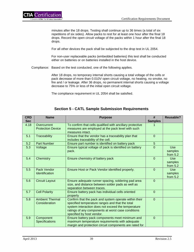
Certification Requirements Document
April 2013 39 Revision 2.5
minutes after the 18 drops. Testing shall continue up to 36 times (a total of six repetitions of six sides). Allow packs to rest for at least one hour after the final 18 drops. Record the open circuit voltage of the packs within 1 hour after the final 18 drops.
For all other devices the pack shall be subjected to the drop test in UL 2054.
For non-user replaceable packs (embedded batteries) this test shall be conducted either on batteries or on batteries installed in the host device.
Compliance: Based on the test conducted, one of the following applies.
After 18 drops, no temporary internal shorts causing a total voltage of the cells or pack decrease of more than 0.010V open circuit voltage, no heating, no smoke, no fire and / or leakage. After 36 drops, no permanent internal shorts causing a voltage decrease to 75% or less of the initial open circuit voltage.
The compliance requirement in UL 2054 shall be satisfied.
Section 5 - CATL Sample Submission Requirements
CRD Sec
Name Purpose # Samples
Reusable?
4.18 Overcurrent Protection Device
To confirm that cells qualified with ancillary protective measures are employed at the pack level with such measures intact.
1
5.1 Traceability Ensure that the vendor has a traceability plan that includes traceability of the cell.
0
5.2 Part Number Ensure part number is identified on battery pack 5
5.3 Voltage Ensure typical voltage of pack is identified on battery pack.
0 Use samples from 5.2
5.4 Chemistry Ensure chemistry of battery pack 0 Use samples from 5.2
5.5 Pack Vendor Identification
Ensure Host or Pack Vendor identified properly. 0 Use samples from 5.2
5.6 Circuit Layout Ensure adequate runner spacing, soldering pad area size, and distance between solder pads as well as separation between traces.
0
5.7 Cell Polarity Ensure battery pack has individual cells oriented properly
0
5.8 Ambient Thermal Consideration
Confirm that the pack and system operate within their specified temperature ranges and that the total system interaction does not exceed the temperature ratings of any components at worst case conditions specified by host vendor.
0
5.9 Component Specifications
Ensure battery pack components meet minimum and maximum temperature requirements with adequate margin and protection circuit components are rated for
0

Certification Requirements Document
April 2013 40 Revision 2.5
operating range of -25°C to +85°C.
5.10 Thermal Consideration
Ensure proper operating (charging and discharging) ranges for battery pack have been set.
0
5.11 Limit Output Validate performance of battery pack short circuit protection.
0 Use samples from 5.2
5.12 Pack Mechanisms Ensure pack has at least one method to limit current from cells independent of the cell separator shutdown mechanism.
0
5.13 Thermal Protection Ensure over-temperature protection has been incorporated that will prevent operation outside current, temperature, and time limits as agreed to by battery pack, cell and host vendor.
0
5.14 Thermal Sensor Design
Validate that a thermal sensor either in the battery pack and/or host monitors cell temperature and enables the system to limit operation within the cell's thermal specifications
5 N
5.15 Action, Thermal Protection
Validate performance of temperature protection during charging.
0
5.16 Charging Specifications
Ensure maximum charging voltage and current have been set based on the component specifications provided by the cell, battery pack and host device vendors.
0
5.17 Charge Considerations
Verify system has one overcurrent protection function that meets maximum current specified in IEEE 1725 section 6.5.1.
0
5.18 Charger Design Validate design of charging system voltage and current control is within maximum specified values.
0
5.19 Protection Identify that the combination of the cell and pack has at least one overvoltage protection function.
0
5.20 Protection Validate performance of the pack/cell overvoltage protection mechanism under a single fault condition in the charger/host and to ensure that two overcharge mechanisms are present in the system.
0
5.21 Specification Ensure proper upper limit discharge current and time limitations have been set.
0
5.22 Pack Overcurrent Protection Requirement
Validate performance of pack discharge overcurrent protection.
5 N
5.23 External Mechanical Force
Validate mechanical robustness for purpose of use. 3 N
5.24 Cell Dimensional Allowance
Ensure proper consideration for the cell and battery pack dimensional tolerances.
0
5.25 Electrical Cell Connections
Ensure that the connections directly to cells are not soldered.
0
5.26 Cell Vent Ensure that the battery pack construction does not prevent cell gases from escaping.
0
5.27 Host Requirement Ensure connector / terminal adhere to the host device mechanical considerations.
0
5.28 ESD Validate the ability of the pack to withstand ESD. 5 N
5.29 Welding Ensure welding is only occurring in areas designated by cell vendor.
0
5.30 Cell Shorts Ensure assembly process avoids cell and battery pack 0

Certification Requirements Document
April 2013 41 Revision 2.5
short-circuit.
5.31 Foreign Objects Ensure assembly process prevents foreign objects from contacting cell or protection circuit.
0
5.32 Soldering Process Ensure adequate means have been provided to prevent solder balls, flashes, bridges, and other solder defects from being introduced during the soldering process.
0
5.33 Reworked Cells Ensure cells salvaged from batteries that are recovered / returned from end users are not used to manufacture battery packs. Review SOP for returned Materials or products.
0
5.34 Circuit Care Ensure precautions have been taken to avoid damage to protection devices and circuits. Review SOP for handling of safety and/or critical components and devices.
0
5.35 Pack Component Care
Ensure precautions have been taken to avoid damage to conductors and insulators, for example, from sharp edges, burrs, pinching, or kinking.
0
5.36 Welding Care Ensure precautions have been taken to avoid damage to cells, protective circuit module, and battery pack housing during housing assembly (ultrasonic welding, over molding, etc.).
0
5.37 ESD Ensure precautions have been taken to avoid damage to protection circuits and other devices from ESD during handling.
0
5.38 Pack Testing During Production
Ensure that all protection circuit operations shall be directly or indirectly verified at the pack level (or pack sub assembly) and 100% of shipped battery packs are tested / verified.
0
5.39 Quality Control Ensure that critical manufacturing processes have quality control and maintenance plans to ensure the consistency of the assembly process and adherence to specifications.
0
5.40 Cell Care Ensure that no damage has occurred during welding and other operations to the cell case or other critical cell design elements.
0
5.41 Specification Ensure voltage, capacity, size, impedance, and other critical specifications have been considered per application for use of cells connected in parallel.
0
5.42 Cell Chemistry Ensure no cells from significantly different electrochemical systems are used to manufacture battery packs.
0
5.43 Fault Considerations
Ensure that adequate precautions have been taken to limit charge rate to the maximum rating of any single cell. FMEA analysis should consider such faults.
0
5.44 Qualification of New Pack Designs
Ensure new pack designs have passed specified tests identified by the vendor before qualification as a production pack.
0
5.45 Qualification of Production Packs
To establish that qualification requirements continue to be met after product has been released for production.
0
5.46 Battery Transportation Regulations
Ensure that vendor complies with transportation regulatory testing requirements including the appropriate sections of UN Manual of Tests and
0
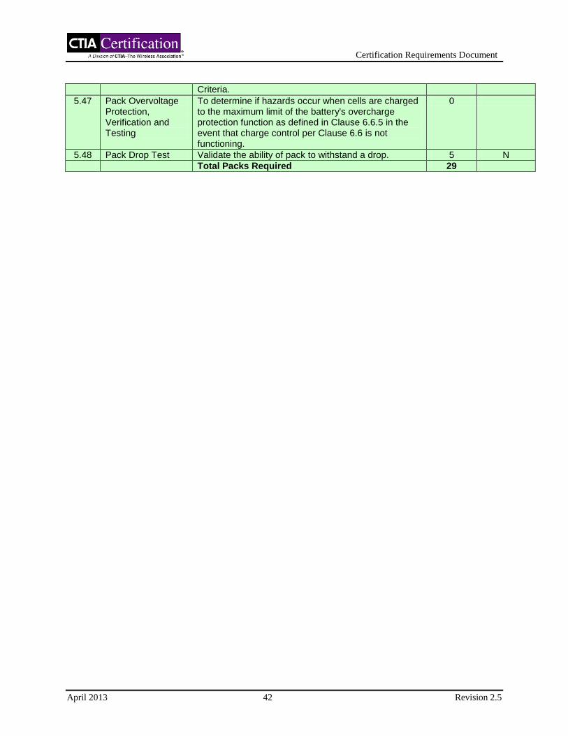
Certification Requirements Document
April 2013 42 Revision 2.5
Criteria.
5.47 Pack Overvoltage Protection, Verification and Testing
To determine if hazards occur when cells are charged to the maximum limit of the battery's overcharge protection function as defined in Clause 6.6.5 in the event that charge control per Clause 6.6 is not functioning.
0
5.48 Pack Drop Test Validate the ability of pack to withstand a drop. 5 N
Total Packs Required 29
Certification Requirements Document
April 2013 43 Revision 2.5
Section 6 Host Device Validation
All tests will be performed on a minimum of 5 samples unless otherwise specified (all samples
must pass compliance).
Inspection/Analysis criteria shall be done on a sample of one.
6.1 Input
Reference: IEEE 1725, Section 7.2.1
Purpose: Ensure specific surge and transient limits are included in the system design specifications.
Procedure: Review system design specifications.
Compliance: For systems with recognized adapters, ensure specific surge and transient limits are included in specification.
For systems without adapters, ensure that the system design specifies the use of a CTIA certified Adapter and/or a USB port in a device that complies with the USB-IF certification requirements.
6.2 Input
Reference: IEEE 1725, Section 7.2.1
Purpose: Validate the ability of the system to filter damaging conducted transient voltages to prevent damage to either the host device's charge control circuitry or the battery pack's safety circuitry.
Procedure: For adaptors with AC mains ports apply transients of 1.2/50(8/20)µs waveform in accordance with IEC 61000-4-5. Ten transients (five positive and five negative) at levels of 1kV line to neutral, 2kV line to ground and 2kV neutral to ground, shall be applied at each zero crossing and peak (0, 90, 180 and 270 degrees phase angle) of the applied ac voltage. Transients shall be applied at a rate of one per minute or less. If testing done at rates faster than one per minute cause failures and tests done at one per minute do not, the test done at one per minute prevails.
For adaptors connected to a vehicle wiring harness, apply pulses 1, 2a, 2b, 3a and 3b in accordance with ISO 7637-2:2011, at test level III, for at least the minimum number of pulses or test time and for the minimum burst duration or at the minimum pulse repetition time.
The equipment shall be on during the test and the battery pack shall be in the fully discharged state at the beginning of the test. If the adaptor has no ground connection only line to neutral transients need to be applied.
When a DC-DC adapter is connected to an AC adapter then the combined unit needs to be tested as an AC adapter.

Certification Requirements Document
April 2013 44 Revision 2.5
For systems without specified adapters (which must have a USB port) shall be tested with certified adapter, three representative adapters shall be tested with the host. The adapters shall be selected by the host manufacturer from available CTIA certified AC and DC adapters. At least one of each type (AC-DC and DC-DC) adapters shall be used for testing.
Compliance: For systems without specified adapters (which must have a USB port) shall be tested with a certified adapters, the battery pack safety circuitry functionality (overcharge, overcurrent, undervoltage) remains after surge regime application, and one full charge/discharge cycle is successfully completed per section 6.11. Compliance can alternatively be met if the pack fails in a demonstrated safe mode. A battery "failing safe" for this requirement is defined as the battery can neither accept charge nor provide discharge. An example might be a fusible link clearing thus fully disabling the pack.
For hosts without adapters, hosts shall meet the above compliance criteria when tested with representative CTIA certified adapters.
6.3 Overvoltage
Reference: IEEE 1725, Section 7.1, 7.2.2
Purpose: Ensure host device is designed to indefinitely withstand the maximum voltage from the adapter, under a single fault condition, to prevent a cascading failure through the system to the battery pack and/or cell.
Procedure: Initiate a charging condition via a way that allows host to charge. Once charging is verified introduce the worst-case faulted overvoltage condition identified in the charging system analysis described in the design analysis tools identified in IEEE 1725 section paragraph 4.1. One sample is required for this test.
Compliance: For systems with recognized adapters, no cascading failure through the system to the battery pack and/or cell after 24 hours. At a minimum a complete charge cycle shall be performed under normal operating conditions to validate performance system specification after application of overvoltage.
For systems without adapters, no cascading failure through the system to the battery pack and/or cell after charging at 9 V for 24 hours. At a minimum a complete charge cycle shall be performed under normal operating conditions to validate performance system specification after application of overvoltage.
6.4 Overcurrent
Reference: IEEE 1725, Section 7.2.3
Purpose: Ensure that the host limits current in such a way that the battery is not charged with a current greater than the maximum charge current specified by the battery vendor.
Procedure: Charge in a system with a battery (or emulated battery) and monitor current through the entire charge cycle. One sample is required for this test.
Compliance: After an initial settling period, the maximum charge current specified by the battery vendor is not exceeded. Such transient effects are limited to charge initiation
Certification Requirements Document
April 2013 45 Revision 2.5
including the pre-charge condition. Repetitive undesirable transients may constitute non-compliance.
6.5 Overcurrent, Faulted
Reference: IEEE 1725, Section 7.2.3
Purpose: Ensure that the host limits current in such a way that the battery is not charged with a current greater than the maximum charge current specified by the battery vendor under the maximum faulted charge current from the adapter.
Procedure: Initiate a charging condition via a way that allows host to charge. Once charging is verified introduce the worst case faulted overcurrent condition identified in the design analysis tools per IEEE 1725 paragraph 4 A sample of one is required.
Compliance: Maximum charge current specified by the battery vendor is not exceeded.
6.6 Fault Isolation and Tolerance
Reference: IEEE 1725, Section 7.2.4, 6.6.5
Purpose: Ensure that IF a system design allows overvoltage or overcurrent to propagate to the
battery pack, the battery pack can withstand this overvoltage and / or overcurrent.
Procedure: Review system documentation.
Compliance: Ensure that an overvoltage or overcurrent condition that propagates to the battery back can be survived by the battery pack.
6.7 Fault Isolation and Tolerance
Reference: IEEE 1725, Section 7.2.4, 6.6.5
Purpose: Validate performance of system level charge over current or over voltage protection during a worst case single fault condition as identified in section 6.6.
Procedure: Setup worst case conditions as identified in section 6.6 for overcurrent situations. Measure current and voltage at the battery pack. Setup worst case conditions as identified in section 6.6 for overvoltage situations. Measure current and voltage at the battery pack.
Compliance: Current and voltage are limited or prevented from propagating to the cell or the pack so the cell/pack can withstand the condition (via protection either in host or pack, or cell).
6.8 Safety
Reference: IEEE 1725, Section 7.3.1
Purpose: Ensure the charging system, or any part of the host device, does not disable or override the safety features inside the battery pack.

Certification Requirements Document
April 2013 46 Revision 2.5
Procedure: Review system documentation.
Compliance: Ensure that charging system or any part of the host device does not disable or override the safety features inside the battery pack.
6.9 Pack Identification
Reference: IEEE 1725, Section 7.3.2
Purpose: Ensure proper identification scheme is employed and at a minimum communicates or indicates the maximum charge voltage.
Procedure: Review system documentation.
Compliance: Determine the identification scheme employed within the system and verify that the maximum charging voltage is communicated or indicated. A mechanical scheme only is not sufficient.
6.10 Pack Identification
Reference: IEEE 1725, Section 7.3.2
Purpose: Exercise the identification scheme in a faulted mode to ensure charging is terminated.
Procedure: Based on analysis interrupt the identification / communication scheme and insert battery and initiate charge. Sample of one is required.
Compliance: Charge current is terminated or not initiated. This requirement applies to removable and embedded packs. For embedded packs the method of compliance may be verifying the cell/pack part number.
6.11 Algorithm Verification
Reference: IEEE 1725, Section 7.3.3
Purpose: Validate proper charge algorithm is identified and executed.
Procedure: Insert fully discharged battery (or emulator) into system and monitor current and voltage during charge cycle. Compare to specification to ensure proper charge current and voltage is provided as specified by the pack vendor. One sample is required.
Compliance: Ensure proper charge current and voltage is provided as specified by the pack vendor.
6.12 Timer Fault
Reference: IEEE 1725, Section 7.3.5
Purpose: Validate the host does not charge for a time period exceeding the system specification.
Certification Requirements Document
April 2013 47 Revision 2.5
Procedure: Determine whether a system specification for maximum charge time exists. If a maximum charge time does exist, charge a battery for a period exceeding the system specification. This is accomplished by using a simulated failed battery or equivalent method that will force the system to continue to charge past the intended time out. Conduct a full charge cycle noting when the system stops charging. A sample size of one is required.
Compliance: Charging stops when specified system charge time is exceeded.
6.13 Communication Fault
Reference: IEEE 1725, Section 7.3.6
Purpose: Validate integrity of communication interface (if present, for example SMBus or I2C)
and proper actions are taken if communication is prevented or interrupted..
Procedure: Prevent or interrupt communications per system specifications and monitor current. A sample of one is required.
Compliance: Charging is terminated or not initiated for systems that employ an electronic communications interface..
6.14 Voltage Range Validation
Reference: IEEE 1725, Section 7.3.8
Purpose: Ensure system checks initial battery voltage.
Procedure: Review system documentation.
Compliance: Ensure system validates initial battery voltage.
6.15 Initiation of Charging Above Specified Voltage Threshold
Reference: IEEE 1725, Section 7.3.8.1
Purpose: Validate charging system does not initiate charging when a battery is above a specified voltage.
Procedure: Charge a battery (or emulator) above the specified voltage or simulate the voltage condition and insert into the charging system (Power applied to charging system prior to insert AND power applied to charging system post insert). A sample of one is required.
Compliance: Monitor current to ensure charging does not initiate per specification.
6.16 Initiation of Charging Below Voltage Threshold
Reference: IEEE 1725, Section 7.3.8.2
Purpose: Validate charging system does not initiate normal charging when a battery is below a specified voltage.

Certification Requirements Document
April 2013 48 Revision 2.5
Procedure: Discharge a battery (or emulator) below the specified voltage or simulate the voltage condition and insert into the charging system (Power applied to charging system prior to insert AND power applied to charging system post insert). A sample of one is required.
Compliance: Monitor current to ensure charging does initiate per pack and cell specification.
6.17 Overdischarge Protection
Reference: IEEE 1725, Section 7.3.8.3
Purpose: If the host incorporates a battery discharge capability feature (normal operation is excluded), Validate that host terminates discharge as defined by pack/cell vendor’s specification.
Procedure: Reduce the voltage at the host/pack interface until the host terminates discharge. Specified nominal discharge current should be utilized to reduce voltage. A sample of one is required.
Compliance: Verify that the pack discharge limit is not exceeded.
6.18 Charging Battery Packs
Reference: IEEE 1725, Section 7.4.2
Purpose: Ensure that in a multi-battery system that the system prevents a battery pack from directly charging another battery pack without use of an appropriate charging subsystem.
Procedure: Review system documentation.
Compliance: Ensure multi-battery systems utilize appropriate charging subsystem to charge batteries.
6.19 Requirements
Reference: IEEE 1725, Section 7.4.1
Purpose: Ensure that multi-battery pack systems implement requirements for the charging algorithm to each battery pack independently.
Procedure: Review system documentation.
Compliance: Ensure multi-battery pack systems have implemented charging algorithm to each battery pack independently.
6.20 Electrostatic Discharge
Reference: IEEE 1725, Section 7.5
Purpose: Validate ESD tolerance of the host to withstand ESD as specified in Annex A table A3 section 8.

Certification Requirements Document
April 2013 49 Revision 2.5
Procedure: Subject host to ESD in accordance with IEC 61000-4-2 per product level 2 at minimum. If a host supports a removable battery pack, ESD testing should be performed on the battery contacts of the host (the battery pack is tested separately under section 5.28). A sample size of one is required.
Additionally, systems without specified adapters, perform the test with the host connected to the Adapter Simulator described in Appendix I – Adapter Simulator.
Compliance: No safety critical failures, such as loss of charge control or damage to battery protection circuitry provided in the host.
6.21 Temperature Specification
Reference: IEEE 1725, Section 7.6
Purpose: Ensure system has incorporated temperature limitations as agreed by cell, battery pack, and host vendor.
Procedure: Review system documentation.
Compliance: System temperature limitation specifications are in agreement with cell, battery pack, and host vendor specifications.
6.22 Mating of Pins
Reference: IEEE 1725, Section 7.8.1.1
Purpose: Ensure host and battery connections mate properly and capable of good electrical contact.
Procedure: Review host and battery pack connector specification.
Compliance: Ensure designs coordinate.
6.23 Mating of Pins
Reference: IEEE 1725, Section 7.8.1.1
Purpose: Validate integrity of connection throughout respective product lifetimes of mating components.
Procedure: Measure contact resistance after life cycle (defined in system specification).
Compliance: Verify that contact resistance is within specification and mechanical integrity precludes shorting of contacts.
6.24 Pin Separation
Reference: IEEE 1725, Section 7.8.1.2
Purpose: Ensure power and ground pins are sufficiently separated.
Procedure: Review host device battery interface.

Certification Requirements Document
April 2013 50 Revision 2.5
Compliance: Power and ground pins are electrically isolated with a minimum distance of 2.5 mm or by a dielectric material between the power and ground contact points.
6.25 Pin Polarity
Reference: IEEE 1725, Section 7.8.1.3
Purpose: Verify battery pack is able to be connected with proper polarity only.
Procedure: Analyze mechanical design of battery pack and host.
Compliance: Ensure that the battery cannot be inserted with incorrect polarity and that electrical contact is made only when the battery pack is properly installed into the host.
6.26 Conductor Ratings
Reference: IEEE 1725, Section 7.8.2
Purpose: Ensure conductors and connectors have proper current rating for the current load with adequate margin as determined by the system vendor.
Procedure: Review electrical tolerance analysis.
Compliance: Conductors and connectors have proper current rating.
6.27 Connector Strength
Reference: IEEE 1725, Section 7.8.3.1
Purpose: Verify connector robustness.
Procedure: Review system documentation and connector specifications.
Compliance: Connection between battery and host is mechanically robust.
6.28 Performance Over Expected Life
Reference: IEEE 1725, Section 7.8.3.2
Purpose: Verify connector robustness.
Procedure: Perform design analysis on connection system.
Compliance: Acceptable contact resistance per specification is maintained over the lifetime of the connection system.
6.29 Metallurgy Consideration
Reference: IEEE 1725, Section 7.8.5
Purpose: Ensure host device and battery pack have compatible metallurgy composition to minimize corrosion and resistance changes.
Certification Requirements Document
April 2013 51 Revision 2.5
Procedure: Review host device and battery pack connector specifications. IEC60950-1 Annex J has a list of metallurgical compatibilities that may be referred to for additional information.
Compliance: Proper metallurgy composition exists within the connection system.
6.30 Mating Force
Reference: IEEE 1725, Section 7.8.6
Purpose: Ensure proper mechanical force between the electrical contact points is maintained.
Procedure: Review system documentation.
Compliance: Design minimizes fretting or other electrical degradation of electrical contact points.
6.31 Shock
Reference: IEEE 1725, Section 7.8.7
Purpose: Validate mechanical robustness of host device for purpose of use.
Procedure: Subject host with a battery pack installed to the following drop test: Drop height 1 meter; one drop per plane; 6 mutually perpendicular planes; drop surface concrete. A sample of one is required for each test.
Compliance: No abnormal heating, no smoke, no fire and / or leakage from battery pack or host.
6.32 Integrity of host charging and charge protection circuitry in the system Foreign
Objects
Reference: IEEE 1725, Section 7.8.8
Purpose: Ensure precautions were taken to minimize the potential for foreign objects and / or liquids to enter the host device and cause a short circuit either during the manufacturing process or end-user operation.
Procedure: Review system documentation.
Compliance: Ensure proper precautions were taken to minimize the potential for foreign objects and / or liquids to enter the host device and cause a short circuit either during the manufacturing process or end-user operation.
6.33 Foreign Objects
Reference: IEEE 1725, Section 7.9
Purpose: Ensure preproduction testing includes all system design criteria in IEEE 1725 7.2, 7.3, 7.4, and 7.5.
Procedure: Review system verification documentation.

Certification Requirements Document
April 2013 52 Revision 2.5
Compliance: Preproduction testing and production sampling include all of the design criteria specified in IEEE 1725, sections 7.2 through 7.5.
6.34 Qualification of New Host Device Designs
Reference: IEEE 1725, Section 7.9.1
Purpose: Ensure new host device designs pass specified tests identified by the vendor before qualification as a production host.
Procedure: Review host device documentation.
Compliance: Ensure tests specified by the vendor were performed and passed.
6.35 Qualification of Production Host Devices
Reference: IEEE 1725, Section 7.9.2
Purpose: Ensure production host devices pass qualification tests at specified intervals.
Procedure: Review host device documentation.
Compliance: Qualification tests are performed and passed as specified by the host vendor at the prescribed intervals.
Section 6 - CATL Sample Submission Requirements
CRD Sec
Name Purpose Host Samples
Pack Samples
Adapter Samples
Reusable?
5.8 Ambient Considerations
Confirm that the pack and host operate within their specified temperature ranges and that the total system interaction does not exceed the temperature ratings of any components at worst case conditions specified by host vendor (such as maximum RF transmit power, gaming applications, video capture or playback, etc.).
1 1 1 N
5.14 5.14 Thermal Sensor Design
Validate that a thermal sensor either in the battery pack and/or host monitors cell temperature and enables the system to limit operation within the cell's thermal specifications
5 5 0 Y
5.15 Action, Thermal Protection
Validate performance of temperature protection during charging.
1 1 1 N
5.23 Mechanical Considerations (Embedded
Validate mechanical robustness for purpose of use.
3 3 0 N
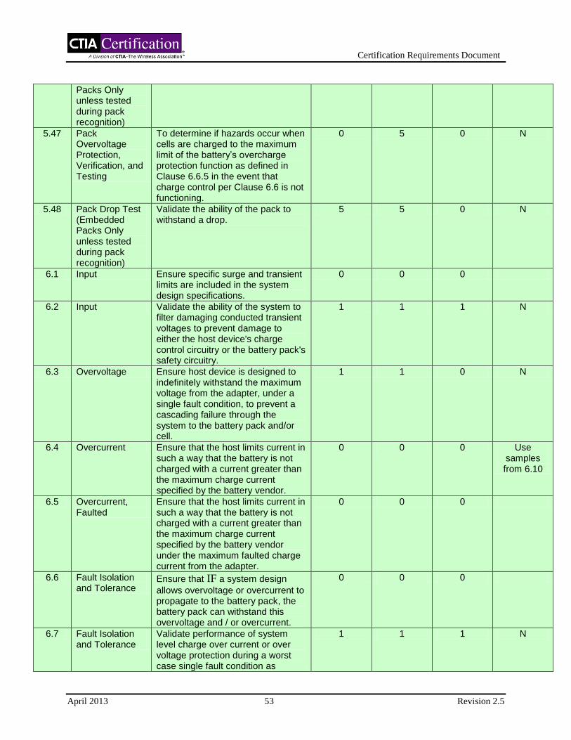
Certification Requirements Document
April 2013 53 Revision 2.5
Packs Only unless tested during pack recognition)
5.47 Pack Overvoltage Protection, Verification, and Testing
To determine if hazards occur when cells are charged to the maximum limit of the battery’s overcharge protection function as defined in Clause 6.6.5 in the event that charge control per Clause 6.6 is not functioning.
0 5 0 N
5.48 Pack Drop Test (Embedded Packs Only unless tested during pack recognition)
Validate the ability of the pack to withstand a drop.
5 5 0 N
6.1 Input Ensure specific surge and transient limits are included in the system design specifications.
0 0 0
6.2 Input Validate the ability of the system to filter damaging conducted transient voltages to prevent damage to either the host device's charge control circuitry or the battery pack's safety circuitry.
1 1 1 N
6.3 Overvoltage Ensure host device is designed to indefinitely withstand the maximum voltage from the adapter, under a single fault condition, to prevent a cascading failure through the system to the battery pack and/or cell.
1 1 0 N
6.4 Overcurrent Ensure that the host limits current in such a way that the battery is not charged with a current greater than the maximum charge current specified by the battery vendor.
0 0 0 Use samples from 6.10
6.5 Overcurrent, Faulted
Ensure that the host limits current in such a way that the battery is not charged with a current greater than the maximum charge current specified by the battery vendor under the maximum faulted charge current from the adapter.
0 0 0
6.6 Fault Isolation and Tolerance
Ensure that IF a system design
allows overvoltage or overcurrent to propagate to the battery pack, the battery pack can withstand this overvoltage and / or overcurrent.
0 0 0
6.7 Fault Isolation and Tolerance
Validate performance of system level charge over current or over voltage protection during a worst case single fault condition as
1 1 1 N
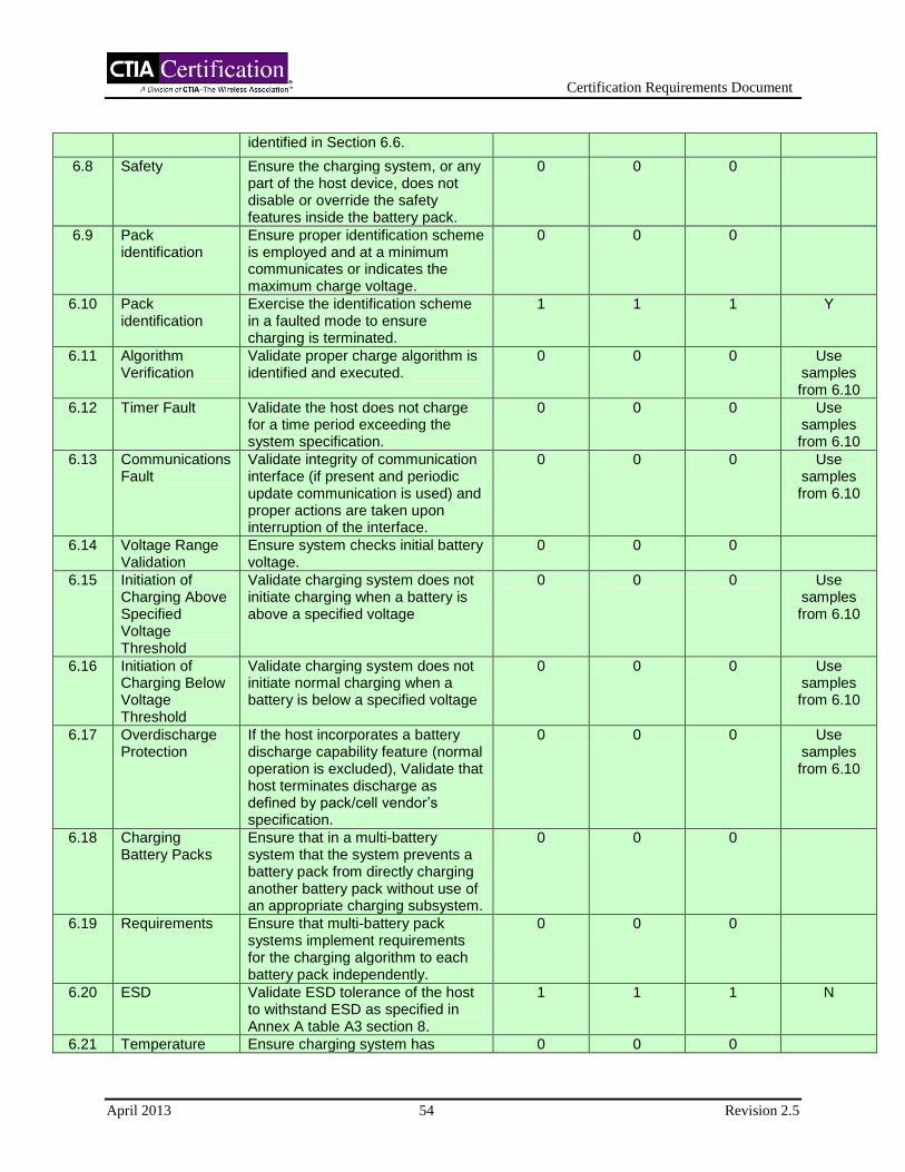
Certification Requirements Document
April 2013 54 Revision 2.5
identified in Section 6.6.
6.8 Safety Ensure the charging system, or any part of the host device, does not disable or override the safety features inside the battery pack.
0 0 0
6.9 Pack identification
Ensure proper identification scheme is employed and at a minimum communicates or indicates the maximum charge voltage.
0 0 0
6.10 Pack identification
Exercise the identification scheme in a faulted mode to ensure charging is terminated.
1 1 1 Y
6.11 Algorithm Verification
Validate proper charge algorithm is identified and executed.
0 0 0 Use samples from 6.10
6.12 Timer Fault Validate the host does not charge for a time period exceeding the system specification.
0 0 0 Use samples from 6.10
6.13 Communications Fault
Validate integrity of communication interface (if present and periodic update communication is used) and proper actions are taken upon interruption of the interface.
0 0 0 Use samples from 6.10
6.14 Voltage Range Validation
Ensure system checks initial battery voltage.
0 0 0
6.15 Initiation of Charging Above Specified Voltage Threshold
Validate charging system does not initiate charging when a battery is above a specified voltage
0 0 0 Use samples from 6.10
6.16 Initiation of Charging Below Voltage Threshold
Validate charging system does not initiate normal charging when a battery is below a specified voltage
0 0 0 Use samples from 6.10
6.17 Overdischarge Protection
If the host incorporates a battery discharge capability feature (normal operation is excluded), Validate that host terminates discharge as defined by pack/cell vendor’s specification.
0 0 0 Use samples from 6.10
6.18 Charging Battery Packs
Ensure that in a multi-battery system that the system prevents a battery pack from directly charging another battery pack without use of an appropriate charging subsystem.
0 0 0
6.19 Requirements Ensure that multi-battery pack systems implement requirements for the charging algorithm to each battery pack independently.
0 0 0
6.20 ESD Validate ESD tolerance of the host to withstand ESD as specified in Annex A table A3 section 8.
1 1 1 N
6.21 Temperature Ensure charging system has 0 0 0
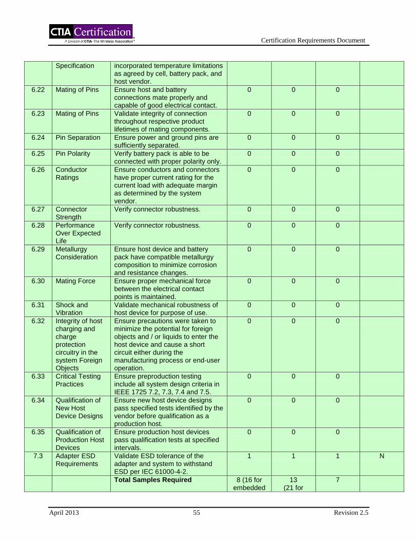
Certification Requirements Document
April 2013 55 Revision 2.5
Specification incorporated temperature limitations as agreed by cell, battery pack, and host vendor.
6.22 Mating of Pins Ensure host and battery connections mate properly and capable of good electrical contact.
0 0 0
6.23 Mating of Pins Validate integrity of connection throughout respective product lifetimes of mating components.
0 0 0
6.24 Pin Separation Ensure power and ground pins are sufficiently separated.
0 0 0
6.25 Pin Polarity Verify battery pack is able to be connected with proper polarity only.
0 0 0
6.26 Conductor Ratings
Ensure conductors and connectors have proper current rating for the current load with adequate margin as determined by the system vendor.
0 0 0
6.27 Connector Strength
Verify connector robustness. 0 0 0
6.28 Performance Over Expected Life
Verify connector robustness. 0 0 0
6.29 Metallurgy Consideration
Ensure host device and battery pack have compatible metallurgy composition to minimize corrosion and resistance changes.
0 0 0
6.30 Mating Force Ensure proper mechanical force between the electrical contact points is maintained.
0 0 0
6.31 Shock and Vibration
Validate mechanical robustness of host device for purpose of use.
0 0 0
6.32 Integrity of host charging and charge protection circuitry in the system Foreign Objects
Ensure precautions were taken to minimize the potential for foreign objects and / or liquids to enter the host device and cause a short circuit either during the manufacturing process or end-user operation.
0 0 0
6.33 Critical Testing Practices
Ensure preproduction testing include all system design criteria in IEEE 1725 7.2, 7.3, 7.4 and 7.5.
0 0 0
6.34 Qualification of New Host Device Designs
Ensure new host device designs pass specified tests identified by the vendor before qualification as a production host.
0 0 0
6.35 Qualification of Production Host Devices
Ensure production host devices pass qualification tests at specified intervals.
0 0 0
7.3 Adapter ESD Requirements
Validate ESD tolerance of the adapter and system to withstand ESD per IEC 61000-4-2.
1 1 1 N
Total Samples Required 8 (16 for embedded
13 (21 for
7

Certification Requirements Document
April 2013 56 Revision 2.5
packs) embedded packs)
Sample count in table is based on single sample submission (1 battery & 1 adapter type). Sample count is based on Recognized Adapter / Battery in system certification. If request is for multiple adapters/batteries (recognized) additional sample count is required.

Certification Requirements Document
April 2013 57 Revision 2.5
Section 7 AC/DC Adapter, DC/DC Adapter Validation
7.1 Adapter Attributes
Reference: IEEE 1725, Section 8.2.1
Purpose: Ensure listed attributes are specified for the adapter.
Procedure: Review adapter specification.
Compliance: Verify adapter specifications include a) maximum output voltage, b) minimum output voltage, c) maximum output voltage under a single fault, d) mechanical attributes that define connector interface (including mechanical design, electrical pin-out, and metallurgy), e) minimum output current, and f) if applicable, electrical interface attributes for identification, authentication, etc.
For certified adapters, ensure that the adapter output is rated 5 ± 0.25 V, 1000 ± 500 mA.
7.2 Adapter and Safety Features
Reference: IEEE 1725, Section 8.2.2
Purpose: Ensure adapter does not disable or degrade the safety features of the supported host device.
Procedure: Review adapter and supported host device documentation.
For certified adapters, perform the single fault test in Section 6.3 and the input test in Section 6.2 utilizing the host simulator in Appendix II – Host Simulator at 0% and 100% loads. During surge testing, voltages on the output of the adapter shall be measured differentially at the host adapter using an oscilloscope. The oscilloscope shall be triggered from the surge generator. During the test the oscilloscope horizontal setting shall be adjusted from 1V/div to 50mV/div and the vertical setting shall be adjusted from 2ms/div to 400ns/div. The largest transients shall be recorded.
Compliance: For systems with recognized adapters, adapter does not disable or degrade the safety features of the supported host device.
For certified adapters, the adapter does not: disable or degrade the safety features of the supported host device; exceed 9 V during the worst case single fault test specified in Section 6.3; or result in transients or voltages greater than ±1 V superimposed on the nominal 5V output circuits during or after the application of the input test specified in Section 6.2.
7.3 Adapter ESD Requirements
Reference: IEEE 1725, Section 8.2.3
Purpose: Validate ESD tolerance of the adapter and/or system to withstand ESD per IEC 61000-4-2.
Certification Requirements Document
April 2013 58 Revision 2.5
Procedure: Subject adapter and system to ESD in accordance with IEC 61000-4-2 per product level 2 as a minimum. Certified adapters must be connected to host simulator for the test.
Compliance: For systems with recognized adapters, no safety critical failures, such as loss of charge control or damage to battery protection circuitry.
For certified adapters, the adapter output must not exceed 9 V after the test.
Note: N/A is only applicable for systems without specified adapters.
7.4 Connector Design of Adapter and Host and Adapter-Host Reliability
Reference: IEEE 1725, Section 8.2.4.1 and 8.2.4.6
Purpose: Verify connector robustness.
Procedure: Perform or review design analysis on connection system.
Compliance: For systems with recognized adapters, acceptable contact resistance is maintained per specification and contact and insulator integrity.
For certified adapters, connectors shall be robust and conform to USB specifications.
7.5 Separation of Pins
Reference: IEEE 1725, Section 8.2.4.2
Purpose: Ensure power and ground pins are sufficiently separated and polarized to ensure that the connection can only be made with proper polarity.
Procedure: Review adapter and host connector specifications.
Compliance: For systems with recognized adapters, spacing and connection are compatible.
For certified adapters, connectors shall conform to the spacings defined in USB specifications.
7.6 Electrical Compliance
Reference: IEEE 1725, Section 8.2.4.3
Purpose: Ensure adapters that are powered by ac mains comply with all electrical safety requirements of the country of destination.
Procedure: Review adapter documentation.
Compliance: Ensure compliance to electrical safety requirements of the country of destination. Minimum marking shall be NRTL (Nationally Recognized Testing Laboratory). Refer to: www.OSHA.gov.
Certification Requirements Document
April 2013 59 Revision 2.5
7.7 Current Ratings
Reference: IEEE 1725, Section 8.2.4.4
Purpose: Ensure conductors and connectors have proper current rating.
Procedure: Review adapter documentation.
Compliance: Ensure conductors and connectors have proper current rating.
7.8 Pin Metallurgy
Reference: IEEE 1725, Section 8.2.4.5
Purpose: Ensure adapter and charger or host connector pins have proper composition to minimize corrosion and resistance changes.
Procedure: Review host device and adapter connector specifications. IEC60950-1 Annex J has a list of metallurgical compatibilities that may be referred to for additional information.
Compliance: For systems with recognized adapters, pin metallurgy is compatible.
For certified adapters, connectors shall comply with USB specifications.
7.9 Shock
Reference: IEEE 1725, Section 8.2.4.7
Purpose: Validate mechanical robustness of adapter for purpose of use.
Procedure: Subject adapter to drop test, six mutually perpendicular planes, 1 (one) drop per plane, height 1 (one), meter drop surface concrete. A sample of one per test is required.
Compliance: Adapters functional normally per product specification. No physical deformation is evident and no mating parts separate during testing.
7.10 Adapter and Foreign Objects
Reference: IEEE 1725, Section 8.2.5
Purpose: Ensure adapter design has taken precautions to minimize the potential for foreign objects and / or liquids to enter the adapter and cause short circuit either during the manufacturing process or end-user operation.
Procedure: Review adapter design.
Compliance: Ensure precautions have been taken to minimize the potential for foreign objects and / or liquids to enter the adapter.
7.11 Adapter Marking and Traceability Requirements
Reference: IEEE 1725, Section 8.2.6

Certification Requirements Document
April 2013 60 Revision 2.5
Purpose: Ensure each vendor has a traceability plan and each adapter carries markings of the production lot and / or date code on the label.
Procedure: Review the adapter documentation.
Compliance: Ensure adapter markings carry the production lot and / or date code on the label and a traceability plan is in place.
7.12 Charger Considerations (AC/DC Charger, DC/DC Charger)
Reference: IEEE 1725, Section 8.3
Purpose: Ensure chargers meet requirements in IEEE1725 clauses 7 and 8.2.
Procedure: Review charger documentation.
Compliance: Compliance to above mentioned clauses.
7.13 Critical Testing Practices
Reference: IEEE 1725, Section 8.4
Purpose: Ensure testing and verification of preproduction and production units includes all system design criteria in IEEE1725 8.2 and 8.3.
Procedure: Review adapter documentation.
Compliance: Testing and verification includes all system design criteria in IEEE1725, Section 8.2 and 8.3.
7.14 Qualification of New Adapter Designs
Reference: IEEE 1725, Section 8.4.1
Purpose: Ensure new adapter designs pass specified tests identified by the vendor before qualification as a production adapter.
Procedure: Review system documentation.
Compliance: Ensure specified tests pass before qualification as a production adapter.
7.15 Qualification of Production Adapters
Reference: IEEE 1725, Section 8.4.2
Purpose: Ensure qualification tests are passed at intervals as specified by the vendor.
Procedure: Review adapter qualification test procedures (to determine required interval and test programs), and adapter test reports.
Compliance: Qualification tests are conducted at the specified intervals and all specified test requirements are passed.

Certification Requirements Document
April 2013 61 Revision 2.5
Section 7 - CATL Sample Submission Requirements
Section Name Purpose Adapter
Samples Reusable?
7.1 Adapter Attributes Ensure adapter meets input requirements of the supported host charging device.
0
7.2 Adapter & Safety Features
Ensure adapter does not disable or degrade the safety features of the supported host device.
0
7.2 Adapter & Safety Features (Certified Adapters Only)
Ensure adapter does not disable or degrade the safety features of the supported host device.
1
7.3 Adapter ESD Requirements
Validate ESD tolerance of the adapter and system to withstand ESD per IEC 61000-4-2.
0
7.3 Adapter ESD Requirements (Certified Adapters Only)
Validate ESD tolerance of the adapter and system to withstand ESD per IEC 61000-4-2.
1
7.4 Connector Design of Adapter and Host and Adapter-Host Reliability
Verify connector robustness. 0
7.5 Separation of Pins Ensure power and ground pins are sufficiently separated and polarized to ensure that the connection can only be made with proper polarity.
0
7.6 Electrical Compliance Ensure adapters that are powered by ac mains comply with all electrical safety requirements of the country of destination.
0
7.7 Current Ratings Ensure conductors and connectors have proper current rating.
0
7.8 Pin Metallurgy Ensure adapter and host connector pins have proper composition to minimize corrosion and resistance changes.
0
7.9 Shock Validate mechanical robustness of adapter for purpose of use.
0
7.10 Adapter and Foreign Objects
Ensure adapter design has taken precautions to minimize the potential for foreign objects and / or liquids to enter the adapter and cause short circuit either during the manufacturing process or end-user operation.
0
7.11 Adapter Marking and Traceability Requirements
Ensure each vendor has a traceability plan and each adapter carries markings of the production lot and / or date code on the label.
0
7.12 Charger Considerations (AC/DC Charger, DC/DC Charger)
Ensure chargers meet requirements in IEEE1725 clauses 7 and 8.2.
0
7.13 Critical Testing Practices
Ensure testing and verification of preproduction and production units includes all system design criteria in IEEE1725 8.2 and 8.3.
0
7.14 Qualification of New Adapter Designs
Ensure new adapter designs pass specified tests identified by the vendor before qualification as a production adapter.
0

Certification Requirements Document
April 2013 62 Revision 2.5
7.15 Qualification of Production Adapters
Ensure qualification tests are passed at intervals as specified by the vendor.
0
Total Samples Required 0 (2 for Certified
Adapters)

Certification Requirements Document
April 2013 63 Revision 2.5
Section 8 Total System Reliability Validation
8.1 User Interactions and Responsibilities
Reference: IEEE 1725, Section 9.2
Purpose: Determine that required user information is provided.
Procedure: Determine by inspection that the following information is made available to the user by one or more of (a) printed on the label for the battery, (b) printed on the label for the host device, (c) printed in the owner's manual, and/or (d) posted in a help file or Internet web site.
a) Do not disassemble or open crush, bend or deform, puncture or shred
b) Do not modify or remanufacture, attempt to insert foreign objects into the battery, immerse or expose to water or other liquids, expose to fire, explosion or other hazard.
c) Only use the battery for the system for which it is specified
d) Only use the battery with a charging system that has been qualified with the system per CTIA Certification Requirements for Battery System Compliance to IEEE 1725. Use of an unqualified battery or charger may present a risk of fire, explosion, leakage, or other hazard.
e) Do not short circuit a battery or allow metallic conductive objects to contact battery terminals.
f) Replace the battery only with another battery that has been qualified with the system per this standard, IEEE-Std-1725. Use of an unqualified battery may present a risk of fire, explosion, leakage or other hazard.
Only authorized service providers shall replace battery. (If the battery is non-user replaceable).
g) Promptly dispose of used batteries in accordance with local regulations
h) Battery usage by children should be supervised.
j) Avoid dropping the phone or battery. If the phone or battery is dropped, especially on a hard surface, and the user suspects damage, take it to a service center for inspection.
k) Improper battery use may result in a fire, explosion or other hazard.
For those host devices that utilize a USB port as a charging source, the host device's user manual shall include a statement that the phone shall only be connected to CTIA certified adapters, products that bear the USB-IF logo or products that have completed the USB-IF compliance program.
Certification Requirements Document
April 2013 64 Revision 2.5
Compliance: Language that communicates the intention of each of the above warnings is included with the product. For non-user-replaceable batteries use sections: a, b, d, g, j, k and the final USB-IF statement.
Certification Requirements Document
April 2013 65 Revision 2.5
Section 9 System Security Validation
9.1 Host and Battery Authentication
Reference: IEEE 1725, Section 10.2.1
Purpose: To ensure that there is an authentication method in place
Procedure: Identify method of authentication that has been implemented.
Compliance: A method of active or passive authentication has been implemented. Embedded batteries are exempt from this requirement.
9.2 Ensuring Supply Chain Security
Reference: IEEE 1725, Section 10.4.1
Purpose: To ensure that adequate security of supply chain is in place and that a security audit plan exists and is being followed.
Procedure: Audit supply chain security process.
Verify that the vendors have documented processes which address the integrity of their supply chain such that no materials enter the supply chain inappropriately. Verify that these processes have been implemented, are being followed and the vendor is periodically verifying compliance to the processes.
Compliance: Practices and/or procedures exist and are followed to ensure supply chain security.
9.3 Avoiding Defective Parts
Reference: IEEE 1725, Section 10.4.2
Purpose: To ensure that adequate security of supply chain, including defective components, is in place and that a security audit plan exists and is being followed. Ensure defective components do not re-enter the supply chain.
Procedure: Audit supply chain security process.
Verify that the vendors have documented processes which address the integrity of their supply chain such that no defective materials enter the supply chain. Verify that these processes have been implemented, are being followed, and the vendor is periodically verifying compliance to the processes.
Compliance: Practices and/or procedures exist and are followed to ensure supply chain security.
Certification Requirements Document
April 2013 66 Revision 2.5
9.4 Battery Pack Identification
Reference: IEEE 1725, Section 10.4.3
Purpose: Determine the vendor has a means of identification within a battery pack to allow verification, by said vendor, of the battery pack and cells if the external housing is destroyed.
Procedure: Review the battery pack documentation to determine the method implemented.
Compliance: A means of identification within the battery pack has been implemented to allow identification of cell(s) and pack, if the external housing is destroyed.

Certification Requirements Document
April 2013 67 Revision 2.5
Section 10 Validation
10.1 Component Requirements
Reference: IEEE 1725, Section 11.3.1
Purpose: Determine by analysis that all system components used in design under test comply with this standard.
For a design to be considered compliant to this standard, all system components used in a design shall be compliant to this standard
Procedure: Determine by analysis that all system components used in design under test comply with this standard.
Compliance: System components comply.
10.2 Record Keeping
Reference: IEEE 1725, Section 11.3.3
Purpose: Determine by inspection that records defining compliance are maintained by the vendor of record.
Records defining compliance shall be maintained by the vendor of record. The specific format of such records is not specified.
Procedure: Inspect documentation.
Compliance: Documentation exists and meets minimum requirements.
10.3 Quality System Requirements
Reference: IEEE 1725, Section 11.4
Purpose: Determine that manufacturer/supplier's quality system meets requirements of ISO-9000.
Procedure: Determine by inspection that manufacturer/supplier holds valid relevant ISO-9000 certificate.
Compliance: Manufacturer/supplier is registered to ISO-9000:2000.
10.4 Definition of Safety Critical Variables
Reference: IEEE 1725, Section 11.5.1 (N/A - See compliance)
Purpose: To ensure that the vendor has defined and documented product and process variables that relate to product safety (safety critical variables).
Procedure: Evaluate the vendor’s product and process documentation.

Certification Requirements Document
April 2013 68 Revision 2.5
Compliance: Safety critical variables have been defined. Compliance to this requirement will not be evaluated separately, but instead will be demonstrated as a part of the cell, pack, host, and system requirements.
10.5 Definition of Critical Measurement Processes
Reference: IEEE 1725, Section 11.5.2 (N/A - See compliance)
Purpose: To ensure that the vendor has defined critical measurement processes for safety critical variables.
Procedure: Evaluate the vendor’s product and process documentation.
Compliance: Critical Measurement processes have been defined for the safety critical variables. Compliance to this requirement will not be evaluated separately, but instead will be demonstrated as a part of the cell, pack, host, and system requirements.
10.6 Confirmation of Critical Measurement Process Capability
Reference: IEEE 1725, Section 11.5.3 (N/A - See compliance)
Purpose: To ensure that the vendor has validated the measurement capability of those critical measurement processes used to assess safety critical variables to both understand and minimize the impact of measurement error.
Procedure: Evaluate the vendor’s product and process documentation, with particular attention to measurement system analysis studies.
Compliance: Critical Measurement processes have been shown to be capable to assess the safety critical variables defined. Compliance to this requirement will not be evaluated separately, but instead will be demonstrated as a part of the cell, pack, host, and system requirements.
10.7 Confirmation of Process Stability
Reference: IEEE 1725, Section 11.5.4 (N/A - See compliance)
Purpose: To ensure that the vendor’s processes that relate to safety critical variables (both product and process) are sufficiently stable such that they can be reliably predicted and thus controlled.
Procedure: Evaluate the vendor’s product and process documentation, with particular attention to process tracking data used to substantiate process stability for process or part qualification.
Compliance: Vendor’s processes that relate to safety critical variables (both product and process) are sufficiently stable. Compliance to this requirement will not be evaluated separately, but instead will be demonstrated as a part of the cell, pack, host, and system requirements.

Certification Requirements Document
April 2013 69 Revision 2.5
10.8 Confirmation of Process Capability
Reference: IEEE 1725, Section 11.5.5 (N/A - See compliance)
Purpose: To ensure that the vendor’s processes that relate to safety critical variables (both product and process) have sufficient process capability in regards to their respective specifications, thus minimizing the chance of an out of specification condition.
Procedure: Evaluate the vendor’s product and process documentation, with particular attention to process capability studies.
Compliance: Vendor’s processes have been shown to be capable of meeting the specifications for the safety critical variables defined with acceptable margin. Compliance to this requirement will not be evaluated separately, but instead will be demonstrated as a part of the cell, pack, host, and system requirements.
10.9 Process Monitoring and Reaction to Out-of-Control Events
Reference: IEEE 1725, Section 11.5.6 (N/A - See compliance)
Purpose: To ensure that the vendor has defined and implemented appropriate process monitoring and control to those processes that relate to safety critical variables (both product and process). Additionally, should an out-of-control event occur, that the vendor conducts an appropriate investigation and, if required, implements necessary corrective actions to bring the process back in control.
Procedure: Evaluate the vendor’s product and process documentation, with particular attention to process control plans and process control data for safety critical process variables, and vendor-provided or incoming inspection data for safety critical product variables.
Compliance: The vendor has defined and implemented appropriate process monitoring and control such that safety critical product and process variables are adequately controlled. Evidence exists that out-of-control events are properly investigated and corrective actions applied where appropriate. Compliance to this requirement will not be evaluated separately, but instead will be demonstrated as a part of the cell, pack, host, and system requirements.
10.10 Process Improvement Actions
Reference: IEEE 1725, Section 11.5.7 (N/A - See compliance)
Purpose: To ensure that the vendor documents and implements an appropriate process improvement strategy to enhance the capability of safety critical product and process variables.
Procedure: Evaluate the vendor’s product and process documentation, with particular attention to product and process improvement strategies and actions.
Compliance: A program of process improvement has been implemented on those processes related to safety critical product and process variables. Compliance to this requirement will not be evaluated separately, but instead will be demonstrated as a part of the cell, pack, host, and system requirements.
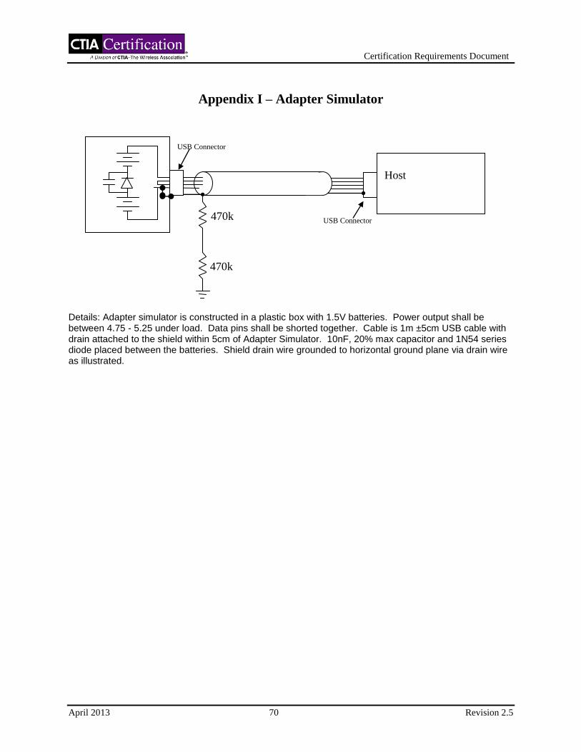
Certification Requirements Document
April 2013 70 Revision 2.5
Appendix I – Adapter Simulator
Details: Adapter simulator is constructed in a plastic box with 1.5V batteries. Power output shall be between 4.75 - 5.25 under load. Data pins shall be shorted together. Cable is 1m ±5cm USB cable with drain attached to the shield within 5cm of Adapter Simulator. 10nF, 20% max capacitor and 1N54 series diode placed between the batteries. Shield drain wire grounded to horizontal ground plane via drain wire as illustrated.
470k
470k
Host
USB Connector
USB Connector

Certification Requirements Document
April 2013 71 Revision 2.5
Appendix II – Host Simulator
Details: Host simulator is constructed in a plastic box and contains non-inductive resistive loads. Cable is 1m ±5cm USB cable. Test points shall be available for monitoring of surge waveform. First resistor is 10k, 10% max tolerance to simulate 0% loads. Other resistors added for 100% loading. More than one path can be created if one host simulator is used for multiple capacities of adapters. Capacitor is ceramic 1uF capacitor with 20% max tolerance. Number of resistors in the Host Simulator is variable, and may be replaced with one or more variable resistors of sufficient power rating.
Adapter 10k
TP
TP
1uF
USB Connector
+
-
+
-

Certification Requirements Document
April 2013 72 Revision 2.5
Appendix III – Change History
Date Revision Description
October 2006 1.0 First Revision
December 2006
1.1 Updated entire document
Changed section headings to match IEEE 1725 section headings
April 2007 1.2 Updated requirements in all sections
July 2007 1.3 Updated Validation Process section
Removed validation type from section titles
Converted types to either Test or Audit (eliminated Inspection and Analysis)
Changed “Subsystem Requirements, Battery Pack” to “Subsystem Requirements, Transport of Dangerous Goods, Battery Pack”
Changed “Subsystem Requirements, Transport of Dangerous Goods” to “Subsystem Requirements, Transport of Dangerous Goods, Cell”
Updated procedure and compliance criteria for Cell Validation - Internal Short Avoidance
Added Cell Thermal Test (Audit) section back in
Updated procedure for Cell Validation - Evaluation of Excess Lithium Plating and Short-Circuit Test on Cycled Cells
Clarified procedure for Battery Pack Validation - Ambient Consideration
Clarified compliance criteria for Battery Pack Validation - Thermal Consideration
Updated procedure and compliance criteria for Battery Pack Validation - Mechanical Considerations
Updated purpose and compliance criteria for Host Device Validation - Input
Clarified procedure for Host Device Validation - Timer Fault
October 2007 1.4 Section 1.3 (Applicable Documents) – clarified that latest version
shall be used
Section 1.4 – added definitions to acronyms
Section 2.2 (Test) – updated description
Section 4.2 (Isolation Properties) – updated compliance
Section 4.38 (Tab Positioning) – updated procedure
Section 4 Sample Size and Re-use Table – added Section 4.51
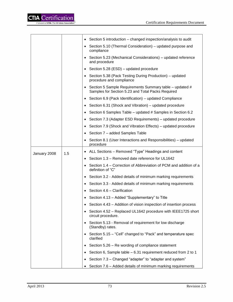
Certification Requirements Document
April 2013 73 Revision 2.5
Section 5 introduction – changed inspection/analysis to audit
Section 5.10 (Thermal Consideration) – updated purpose and compliance
Section 5.23 (Mechanical Considerations) – updated reference and procedure
Section 5.28 (ESD) – updated procedure
Section 5.38 (Pack Testing During Production) – updated procedure and compliance
Section 5 Sample Requirements Summary table – updated # Samples for Section 5.23 and Total Packs Required
Section 6.9 (Pack Identification) – updated Compliance
Section 6.31 (Shock and Vibration) – updated procedure
Section 6 Samples Table – updated # Samples in Section 6.2
Section 7.3 (Adapter ESD Requirements) – updated procedure
Section 7.9 (Shock and Vibration Effects) – updated procedure
Section 7 – added Samples Table
Section 8.1 (User Interactions and Responsibilities) – updated procedure
January 2008 1.5 ALL Sections – Removed “Type” Headings and content
Section 1.3 – Removed date reference for UL1642
Section 1.4 – Correction of Abbreviation of PCM and addition of a definition of “C”
Section 3.2 - Added details of minimum marking requirements
Section 3.3 - Added details of minimum marking requirements
Section 4.6 – Clarification
Section 4.13 – Added “Supplementary” to Title
Section 4.43 – Addition of vision inspection of insertion process
Section 4.52 – Replaced UL1642 procedure with IEEE1725 short circuit procedure.
Section 5.13 - Removal of requirement for low discharge (Standby) rates.
Section 5.15 – “Cell” changed to “Pack” and temperature spec clarified
Section 5.26 – Re wording of compliance statement
Section 6, Sample table – 6.31 requirement reduced from 2 to 1
Section 7.3 – Changed “adapter” to “adapter and system”
Section 7.6 – Added details of minimum marking requirements

Certification Requirements Document
April 2013 74 Revision 2.5
March 2008 1.6 Section 4.2 – Updated procedure for clarification.
Section 4.3 – Updated procedure to remove “Auditor to ask for” and added review
Section 4.6 – Updated compliance, replaced measurements with measurement data
Section 4.11 – Updated purpose and added “tab”. Updated procedure to remove “Auditor to ask for”
Section 4.12 – Updated procedure to add “Not applicable to the cells that have more than one single tab at cell core initiation (such as stacking or folding configurations).”
Section 4.13 – Updated procedure to add “Not applicable to the cells that have more than one single tab at cell core initiation (such as stacking or folding configurations).”
Section 4.14 – Updated procedure to delete randomly selected. Added “Not applicable to the cells that have more than one single tab at cell core initiation (such as stacking or folding configurations).”
Section 4.15 – Updated procedure for clarification. Deleted “Inspect production line and note the insulation material used.”
Section 4.16 – Updated procedure, replaced “Air, N2, Ar etc.” with “Air or inert gas (e.g. N2, Ar etc.)”
Section 4.23 – Updated procedure for clarification, deleted “by sampling”
Section 4.24 – Updated procedure to add “heights” and delete “lengths”
Section 4.25 – Deleted “length” from clause title, Updated purpose to replace lengths with heights
Section 4.30 – Updated compliance, added missing letter “m” and (winding processes only)
Section 4.33 – Updated purpose, procedure and compliance, added “core assembly” and deleted “winding”.
Section 4.37 – Updated procedure, added “and manufacturing inspection processes”
Section 4.39 – Updated procedure for clarification
Section 4.42 – Updated procedure for clarification. Updated compliance to add “Additionally, the process control documentation confirms that the insulating material is checked with resistive measurement or other technological means or methods.”
Section 4.43 – Updated procedure for clarification, added “Ensure that manufacturer’s vision system is calibrated and repeatable.”
Section 4.48 – Updated procedure and compliance, deleted

Certification Requirements Document
April 2013 75 Revision 2.5
“Auditor”
Section 5.47 – Updated procedure, added “Alternative method to insulate the cells (with minimum thermal resistance with R value of 5) can be used to perform this test.”
Section 6.4 – Updated compliance, added “After an initial settling period, the” and “Such transient effects are limited to charge initiation including the pre-charge condition. Repetitive undesirable transients may constitute non-compliance.”
Section 9.2 – Updated procedure, deleted “The auditor shall”
Section 9.3 – Updated procedure, deleted “The auditor shall”
Section 4 – Updated Sample Size and Re-use Table, added purpose
Section 7 - Updated Samples table, added purpose
July 2008 1.7 Section 1.4 - Replaced "C" definition with C – Rated capacity of
a Battery or Cell as defined by IEC 62133 and UL 2054.
Section 2 - Revised paragraph to refer to CRSL for variable definitions.
Section 2.1 - Deleted based on change to Section 2.
Section 2.2 - Deleted based on change to Section 2.
Section 4.13 - Added "unless demonstrated by documented evaluation report" to Compliance statement.
Section 4.43 - Deleted repetitive "4.43".
Section 5.14 - Changed procedure statement from "one" to "five" samples.
Section 5.19 - Edited Purpose, Procedure and Compliance statements to require one overvoltage protection function for the combination of the cell and pack. Deleted any references to "host" and "overcharge".
Section 5.28 - Deleted "6.11" from Compliance statement.
Section 5.38 - Added "electronic" to Purpose and Procedure statement. Replaced Compliance statement with "100% testing of the electronic protection circuit(s) is performed during the manufacturing process".
Section 5.43 - Replaced Compliance statement with "The manufacturer/supplier shall take adequate precautions to ensure that the charge rate does not exceed the maximum of any single cell in the event that the other cell(s) should become electrically disconnected."
Section 5 - Sample Requirements Summary - Changed "# Samples" to "5".
Section 6.31 - Deleted "and Vibration" from section title.

Certification Requirements Document
April 2013 76 Revision 2.5
Section 7.9 - Deleted "and Vibration Effects" from section title. Deleted " Vibration: Directly secure adapters to the vibration table. The adapters shall be randomly vibrated per MIL-STD-810F method 514.5, Procedure I, Category 24, per Figure 514.5C-17. The test time shall be one hour per plane for three planes." from Procedure statement.
October 2008
1.8 General - Ambient Temperature defined in Section 1.4 as 20 ± 5
°C. "Room" replaced with "ambient" in Sections 4.2, 4.4, 4.5, 4.50, 4.52, 5.8, 5.22 and 5.28; Table of Contents 4.4 and 5.8; and Section 5 - Sample Requirements Summary Table CRD Sec 5.8.
Section 3.7 Compliance - Replaced "documentation from UL that the cell is recognized and how the recognition was achieved" with "evidence showing that all tests called for in UL 1642 (user-replaceable) have passed".
Section 4.4 Compliance - Replaced "Measurements shall demonstrate 0.1 mm separator coverage on each side (plus process margin). If less than 0.1 mm overlap is observed, the cell manufacturer shall submit supporting safety evidence" with "Measurements shall demonstrate at least 0.1 mm separator coverage on each side (plus process margin). If less than 0.1 mm overlap is observed, the cell manufacturer shall submit supporting safety evidence".
Section 4.36 Compliance - Deleted extra "4" from header. Deleted "that" and "are" from "Validate the method of assembly for insulating material properties is sufficient to provide protection from shorts over the projected lifetime of the cell" in Compliance statement. Inserted "method of assembly for" after "Validate the" in second sentence.
Section 4.50 Compliance - Replaced "5 cells at 100% SOC shall be suspended (no heat transfer allowed to non-integral cell components) in a gravity convection or circulating air oven at room temperature. The oven temperature shall be ramped at 5 ± 2°C per minute to 130 ± 2°C. After 1 hour at 130 ± 2°C, the test is ended." with "5 fully charged cells (per cell manufacture's specifications) shall be suspended (no heat transfer allowed to non-integral cell components) in a gravity convection or circulating air oven at ambient temperature. The oven temperature shall be ramped at 5 ± 2°C per minute to 130 ± 2°C. After 1 hour at 130 ± 2°C, the test is ended".
Section 5.14 Compliance - Replaced "The thermistor continues to track cell temperature throughout the entire operating temperature range of the battery pack. Packs of the same model shall have the same voltage to temperature translation (acceptable tolerance no more than ±10%)" with "Verify the resistance of the battery pack's thermistor circuit, if used, is within +/-10% of the temperature-resistance translation, as specified by the thermistor manufacturer and battery pack designer, over the operating temperature range of the battery".

Certification Requirements Document
April 2013 77 Revision 2.5
Section 5.23 Procedure - Replaced "Steady Force test shall be performed per UL 2054 paragraph 19" with "If the battery pack is user replaceable, perform the Steady Force test per UL 2054 on the battery pack. If the pack is non-user replaceable, the test may optionally be performed on the host device with the battery pack installed".
Section 5 - Sample Requirements Summary Table - Changed "Y" to "N" in "# Samples" column in "CRD Sec" rows 5.11 and 5.22.
Section 6.16 Compliance - Replaced "cell" with "pack".
Section 9.4 Purpose - Replaced "Determine that the manufacturer has a means of identification within a battery pack to allow verification, by said manufacturer, of the battery pack and cells" with "Determine the manufacturer has a means of identification within a battery pack to allow verification, by said manufacturer, of the battery pack and cells if the external housing is destroyed".
Section 9.4 Compliance - Replaced "A means of identification has been implemented" with "A means of identification within the battery pack has been implemented to allow identification of cell(s) and pack, if the external housing is destroyed".
January 2009 1.9 Section 4 Sample Table - Corrected sample count and reuse
status based on current CRD and CRSL.
Section 5 Sample Table - Section 4 Sample Table - Corrected sample count and reuse status based on current CRD and CRSL.
Section 6 Sample Table - Section 4 Sample Table - Corrected sample count and reuse status based on current CRD and CRSL.
Section 7 Sample Table - Section 4 Sample Table - Corrected sample count and reuse status based on current CRD and CRSL.
March 2009
1.10 Section 6.2 Purpose - Replaced " Connect the system and
ensure the charging process is operating; the battery pack should have a state of charge greater than 90%. Inject Power Surges and transients per IEC 61000-4-5. Perform verification of over-current, overvoltage, and undervoltage functionality. Also conduct one charge-discharge cycle per section 6.11." with ” For adaptors with AC mains ports apply transients of 1.2/50(8/20)µs waveform in accordance with IEC 61000-4-5. Ten transients (five positive and five negative) at levels of 1kV line to neutral, 2kV line to ground and 2kV neutral to ground, shall be applied at each zero crossing and peak (0, 90, 180 and 270 degrees phase angle) of the applied ac voltage. Transients shall be applied at a rate of one per minute. The equipment shall be on during the test and the battery pack shall be in the fully discharged state at the beginning of the test. If the adaptor has no ground connection only line to neutral transients need to be

Certification Requirements Document
April 2013 78 Revision 2.5
applied." and " When a DC-DC adapter is connected to an AC adapter then the combined unit needs to be tested as an AC adapter."
Section 5.14 Compliance - Add "Verify that the thermistor resistance represents the temperature of the cell based on the pack manufacturers specification."
Section 4 Sample Table 4.9 - Removed "Electrode Capacity Balance and" in "Name" column.
Section 4 Sample Table 4.14 - Added "Supplementary" after "of" in "Name" column.
Section 5 Sample Table 4.18 - Removed "Y" from "Reusable" column.
Section 5 Sample Table 5.2 - Replaced "0" with "5" in "# samples" column.
Section 5 Sample Table 5.2 - Removed "Use samples from 4.18" from "Reusable" column.
Section 5 Sample Table 5.2-5.5, 5.11 - Replaced "Use samples from 4.18" with "Use samples form 5.2" in "Reusable" column.
Section 5 Sample Table 5.11 - Replace "5" with "0" in "# of samples" column.
Section 5 Sample Table Total Packs Required - Replaced "28" with "29" in "# of samples" column.
Section 5.48 Compliance - Added "of the cells or pack" after "voltage" in the first sentence.
June 2009 1.11 Section 5 Sample Table 5.47 - Replaced "5" with "0" in "# of
samples" column and removed "N" from "Reusable?" column.
Section 5 Sample Table 5.48 - Replaced "0" with "5" in "# of samples" column and added "N" to "Reusable?" column.
Section 6.2 Procedure - Added "or less. If testing done at rates faster than one per minute cause failures and tests done at one per minute do not, the test done at one per minute prevails." to the last sentence of first paragraph.
Section 6.2 Procedure - Added " For adaptors connected to a vehicle wiring harness, apply pulses 1, 2a, 2b, 3a, 3b and 4 in accordance with ISO 7637-2, at test level III, for at least the minimum number of pulses or test time and for the minimum burst duration or at the minimum pulse repetition time." after first paragraph.
Section 6 Sample Table 6.5 - Deleted "Use samples from 6.4" from "Reusable?" column.
Section 6 Sample Table - Added Rows for 5.23 and 5.48 to address embedded packs requiring 5 pack samples.
November 2009
1.12 Section 1.4 Ambient Temperature - Changed "20" to "25".

Certification Requirements Document
April 2013 79 Revision 2.5
Section 4.52 Procedure - Changed "25ºC" to "Ambient Temperature".
Section 4 Sample Table - Changed title of Table from "Samples Table" to "CATL Sample Submission Requirements".
Section 5.11 Reference - Deleted repetitious "Section".
Section 5.11 Procedure - Added "Before the test, the battery pack shall be fully charged according to Table A.2—Brief description of battery pack electrical tests of IEEE1725-2006, or according to the manufacturer’s specifications."
Section 5.23 Procedure - Added "3 samples of" after "on" in the first sentence.
Section 5.48 Procedure - Added "at least" after "for" in sentence 6.
Section 5.48 Compliance - Deleted "measured one hour after completing drop test" from last sentence.
Section 5 Sample Table - Changed title of Table from "Samples Table" to "CATL Sample Submission Requirements".
Section 6.16 Compliance - Added "and cell" after "pack" to sentence.
Section 6.20 Compliance - Added "provided in the host" to sentence.
Section 6 Sample Table - Changed title of Table from "Samples Table" to "CATL Sample Submission Requirements".
Section 6 Sample Table 5.23 - Changed "5" to "3".
Section 6 Sample Table Total Samples Required - Added "16 for embedded packs" to Host column.
Section 7 Sample Table - Changed title of Table from "Samples Table" to "CATL Sample Submission Requirements".
February 2010 1.13 Replaced "supplier" and "manufacturer" with "Vendor".
Table of Contents, 4.15 - Deleted comma after "ADHERENCE".
Sections 1.1 and 1.3 – Removed references to CTIA Certification Program Management document
Section 4.15 Title - Deleted comma after "Adherence".
Section 4.44 Reference - Replaced "&" with "and".
Section 5.15 Reference - Replaced "Section" with "and".
Section 6.9 Title - Capitalize "I" in "Identification".
Section 7.8 Purpose - Added "charger or" to first sentence.
April 2010 1.14
Section 1.3 - Added "or latest Revision" after "(ST/SG/AC.10/11/Rev4)".
Section 1.3 - Added " Universal Serial Bus Specification,
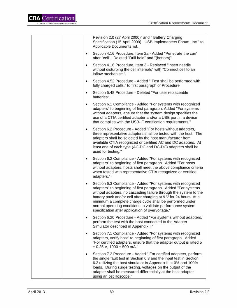
Certification Requirements Document
April 2013 80 Revision 2.5
Revision 2.0 (27 April 2000)" and " Battery Charging Specification (15 April 2009). USB Implementers Forum, Inc." to Applicable Documents list.
Section 4.16 Procedure, Item 2a - Added "Penetrate the can" after "cell". Deleted "Drill hole" and "(bottom)".
Section 4.16 Procedure, Item 3 - Replaced "Insert needle without disturbing the cell internals" with "Connect cell to an inflow mechanism".
Section 4.52 Procedure - Added " Test shall be performed with fully charged cells." to first paragraph of Procedure
Section 5.48 Procedure - Deleted "For user replaceable batteries".
Section 6.1 Compliance - Added "For systems with recognized adapters" to beginning of first paragraph. Added "For systems without adapters, ensure that the system design specifies the use of a CTIA certified adapter and/or a USB port in a device that complies with the USB-IF certification requirements."
Section 6.2 Procedure - Added "For hosts without adapters, three representative adapters shall be tested with the host. The adapters shall be selected by the host manufacturer from available CTIA recognized or certified AC and DC adapters. At least one of each type (AC-DC and DC-DC) adapters shall be used for testing."
Section 6.2 Compliance - Added "For systems with recognized adapters" to beginning of first paragraph. Added "For hosts without adapters, hosts shall meet the above compliance criteria when tested with representative CTIA recognized or certified adapters."
Section 6.3 Compliance - Added "For systems with recognized adapters" to beginning of first paragraph. Added "For systems without adapters, no cascading failure through the system to the battery pack and/or cell after charging at 9 V for 24 hours. At a minimum a complete charge cycle shall be performed under normal operating conditions to validate performance system specification after application of overvoltage."
Section 6.20 Procedure - Added "For systems without adapters, perform the test with the host connected to the Adapter Simulator described in Appendix I."
Section 7.1 Compliance - Added "For systems with recognized adapters, verify host" to beginning of first paragraph. Added "For certified adapters, ensure that the adapter output is rated 5 ± 0.25 V, 1000 ± 500 mA."
Section 7.2 Procedure - Added " For certified adapters, perform the single fault test in Section 6.3 and the input test in Section 6.2 utilizing the host simulator in Appendix II at 0% and 100% loads. During surge testing, voltages on the output of the adapter shall be measured differentially at the host adapter using an oscilloscope."

Certification Requirements Document
April 2013 81 Revision 2.5
Section 7.2 Compliance - Added "For systems with recognized
adapters" to beginning of first paragraph. Added "For certified adapters, the adapter does not: disable or degrade the safety features of the supported host device; exceed 9 V during the worst case single fault test specified in Section 6.3; or result in transients or voltages greater than 12 V on the output circuits during or after the application of the input test specified in Section 6.2."
Section 7.3 Compliance - Added "For systems with recognized adapters" to beginning of first paragraph. Added "For certified adapters, the adapter output must not exceed 9 V after the test."
Section 7.4 Compliance - Added "For systems with recognized adapters" to beginning of first paragraph. Added "For certified adapters, connectors shall be robust and conform to USB specifications."
Section 7.5 Compliance - Added "For systems with recognized adapters" to beginning of first paragraph. Added "For certified adapters, connectors shall conform to the spacings defined in USB specifications."
Section 7.8 Compliance - Added "For systems with recognized adapters" to beginning of first paragraph. Added "For certified adapters, connectors shall comply with USB specifications."
Section 8.1 Procedure - Added "CTIA certified adapters" after "connected to" in last paragraph.
Added Appendix I - Adapter Simulator.
Added Appendix II - Host Simulator.
Moved Change History to Appendix III.
September 2010
1.15
Section 3.4 Purpose and Procedure - Deleted "UN (ST/SG/AC.10/11) Rev 4-2003 Section 38.3 Lithium Batteries"
Section 3.5 Purpose and Procedure - Deleted "UN (ST/SG/AC.10/11) Rev 4-2003 Section 38.3 Lithium Batteries".
Section 4.16 Procedure 3) - Replace "Insert needle" with "Connect cell to an inflow mechanism".
Section 5.46 Purpose - Replace "Ensure that vendor complies with transportation regulatory testing requirements including the appropriate sections of UN Manual of Tests and Criteria" with "Ensure compliance to UN Recommendations on the Transport of Dangerous Goods, Manual of Tests and Criteria".
Section 5.46 Procedure - Replace "Review results of UN Transport testing for the design under evaluation" with "Confirm compliance to UN Recommendations on the Transport of Dangerous Goods, Manual of Tests and Criteria"
Section 5.46 Compliance - Replace "Complies with UN Manual of Tests and Criteria, 4th edition, Part III, sub-section 38.3" with "Vendor declaration of compliance document provided".

Certification Requirements Document
April 2013 82 Revision 2.5
Section 7.2 Procedure - Add "The oscilloscope shall be triggered from the surge generator. During the test the oscilloscope horizontal setting shall be adjusted from 1V/div to 50mV/div and the vertical setting shall be adjusted from 2ms/div to 400ns/div. The largest transients shall be recorded." to end of second paragraph.
Section 7.2 Compliance - Added "±1 V superimposed on the nominal 5V" after "greater than" and deleted "12 V on the" in second paragraph.
Appendix I - Added "Power output shall be between 4.75 - 5.25 under load." after "1.5 V batteries". Deleted "Batteries are “floating” to ground".
Appendix I - Moved shield to ground short to inside of Adapter simulator.
Appendix II - Added "Number of resistors in the Host Simulator is variable, and may be replaced with one or more variable resistors of sufficient power rating." to end of paragraph.
Appendix II - Moved shield to ground short at inside of Host simulator.
November 2010
1.16 Section 7 Sample Table - Added sample requirement of "1" to
7.2 and 7.3 for Certified Adapters.
Section 8.1 Procedure - Added letters a through k (no i) to the beginning of each item.
Section 8.1 Compliance - Added " For non-user-replaceable batteries use sections: a, b, d, g, j, k and the final USB-IF statement."
May 2011 1.17
Section 1.3 - Replaced "Recommendations on the Transport of Dangerous Goods, Manual of Tests and Criteria, Fourth Revised Edition, United Nations, New York and Geneva, 2003, (ST/SG/AC.10/11/Rev4) or latest Revision." with "Recommendations on the Transport of Dangerous Goods, Manual of Tests and Criteria, Part III, Sub-section 38.3, Fourth or Fifth Revised Edition, United Nations, New York and Geneva."
Section 1.4 - Replaced "Ambient Temperature: 25 ± 5 °C" with "Ambient Temperature: 20 ± 5 °C".
Section 3.4 Procedure - Replaced "Confirm compliance to UN Recommendations on the Transport of Dangerous Goods, Manual of Tests and Criteria." with "Review test report confirming compliance to UN Recommendations on the Transport of Dangerous Goods, Manual of Tests and Criteria.”
Section 3.4 Compliance - Replace "Confirm compliance to UN Recommendations on the Transport of Dangerous Goods, Manual of Tests and Criteria." with "Test report confirming compliance to UN Recommendations on the Transport of Dangerous Goods, Manual of Tests and Criteria exists."
Certification Requirements Document
April 2013 83 Revision 2.5
Section 3.5 Procedure - Replaced "Confirm compliance to UN Recommendations on the Transport of Dangerous Goods, Manual of Tests and Criteria." with "Review test report confirming compliance to UN Recommendations on the Transport of Dangerous Goods, Manual of Tests and Criteria.”
Section 3.5 Compliance - Replace "Confirm compliance to UN Recommendations on the Transport of Dangerous Goods, Manual of Tests and Criteria." with "Test report confirming compliance to UN Recommendations on the Transport of Dangerous Goods, Manual of Tests and Criteria exists."
Section 4.49 Purpose - Replace "To ensure the cell model meets transportation regulatory testing requirements including those listed in appropriate sections of UN Manual of Tests and Criteria." with "Ensure compliance to UN Recommendations on the Transport of Dangerous Goods, Manual of Tests and Criteria.”
Section 4.49 Procedure - Replace "Refer to 3.5" with "Review test report confirming compliance to UN Recommendations on the Transport of Dangerous Goods, Manual of Tests and Criteria."
Section 4.49 Compliance - Replace "Refer to 3.5" with "Test report confirming compliance to UN Recommendations on the Transport of Dangerous Goods, Manual of Tests and Criteria exists."
Section 4.52 - Replaced "Ambient Temperature" with "25 ± 5 °C".
Section 5.46 Procedure - Replaced "Confirm compliance to UN Recommendations on the Transport of Dangerous Goods, Manual of Tests and Criteria." with "Review test report confirming compliance to UN Recommendations on the Transport of Dangerous Goods, Manual of Tests and Criteria.”
Section 5.46 Compliance - Replace "Confirm compliance to UN Recommendations on the Transport of Dangerous Goods, Manual of Tests and Criteria." with "Test report confirming compliance to UN Recommendations on the Transport of Dangerous Goods, Manual of Tests and Criteria exists."
August 2011 2.0
Section 1.1 - Replace "2006" with "2011".
Section 1.3 - Update IEEE 1725 with current revision.
Section 3.7 Purpose - Delete "User Replaceable Batteries".
Section 3.7 Procedure - Delete "User Replaceable Batteries".
Section 3.7 Compliance - Delete "(user-replaceable)".
Section 4.15 Title - Delete "Adherence and".
Section 4.15 Reference - Delete "and 5.2.5.3".
Section 4.24 Purpose, Procedure and Compliance - Complete rewrite.
Certification Requirements Document
April 2013 84 Revision 2.5
Section 5.25 Purpose - Add "This is not applicable if design prevention is present."
Section 5.25 Procedure - Add "This is not applicable if design prevention is present."
Section 5.25 Compliance - Add "This is not applicable if design prevention is present."
Section 4.38 Purpose - Replace "controlled to prevent short circuit" with "controlled to prevent cell core assembly damage or tab/can short circuits."
Section 4.38 Compliance - Replace "The position of negative and positive tabs are staggered so they do not overlap each other." to "Verify the position of negative and positive tabs do not create cell core assembly damage or tab/can short circuits. Alternatively, verify an insulator gasket isolates the tabs from the cell core assembly and can walls."
Section 4.40 Title - Replace "/Stack" with "Assembly".
Section 4.41 Title - Replace "Plate" with "Material".
Section 4.41 Purpose - Replace "To confirm the characteristics of the material, color, proper positioning and presence of insulating materials" with "To ensure an insulating method prevents shorting of cell core to the cell casing."
Section 4.41 Procedure - Replace "insulation plate" with "insulating method".
Section 4.41 Compliance - Replace "If the design requires an insulation plate, the plate shall be properly positioned and readily visible" with " Verify insulating method and verify insulating material is readily visible".
Section 4.42 Reference - Add "(NA - See 4.41)".
Section 4.43 Purpose - Replace "The proper alignment of positive and negative electrodes is critical to prevent hazards. The vendor shall conduct 100% inspection (post-winding or stacking of electrodes) and should use a vision system to inspect 100% of the electrode assemblies." with "The vendor shall use a vision system to inspect 100% of the cell cores".
Section 4.43 Compliance - Replace "each" with "all" and add "s or vendors supporting evidence justifies a lesser minimum overlap" to "side".
Section 4.46 Title - Capitalize "during".
Section 4.53 Reference - Add "(N/A - See 4.52, IEEE reference deleted in 2011 edition)".
Section 5.3 Compliance - Add "Embedded batteries are exempt from this requirement."
Section 5.4 Compliance - Add "Embedded batteries are exempt from this requirement."
Certification Requirements Document
April 2013 85 Revision 2.5
Section 5.8 Title - Add "Thermal" after "Ambient"
Section 5.8 Purpose - Replace "Confirm that the pack and host operate within their specified temperature ranges and that the total system interaction does not exceed the temperature ratings of any components at worst case conditions specified by host vendor" with "Confirm that thermal specifications of battery pack components are not exceeded when the pack is operated at the maximum-rated charge and the maximum rated discharge current, with the pack ambient temperature elevated to the maximum temperature specification of the host"
Section 5.8 Procedure - Replace "battery pack vendors specification" with " test results". Replace "worst case" with "maximum rated" in paragraphs 2, 5 and 6. Replace "temperature extremes" with "maximum operating temperature in paragraph 2". Add "(This simulates operating conditions in a host that are expected to produce maximum temperatures in the battery pack)" after "monitored temperatures" in paragraphs 5 and 6.
Section 5.14 Title - Replace "Protection" with "Sensor"
Section 5.14 Purpose - Replace "the thermistor, if used, adequately represents the temperature of the cell" with "a thermal sensor either in the battery pack and/or host monitors cell temperature and limits works with the system to limit operation within the cell's thermal specifications".
Section 5.14 Procedure - Replace "thermistor resistance" with "cell temperature". Add "operating the system and" after "while" and "and "beyond" after "throughout". Delete "of the system. A sample of five is required".
Section 5.14 Compliance - Replace "resistance of the battery pack's thermistor circuit, if used, is within +/-10% of the temperature-resistance translation, as specified by the thermistor vendor and battery pack designer, over the operating temperature range of the battery. Verify that the thermistor resistance represents the temperature of the cell based on the pack vendors specification" with "thermal protection mechanism limits operation within the cell's thermal specification".
5.15 Compliance - Replace " Charging is disabled when operating temperature limits of the Pack are exceeded" with Charging is disabled or other protective action is taken when the operating limits of the cell are exceeded".
Section 5.17 Compliance - Add "provided it limits the current to the maximum current specified in IEEE 6.6.1".
Section 5.23 Title - Replace "Mechanical Considerations" with "External Mechanical Force".
Section 5.23 Reference - Replace "6.9" with "6.9.9".
Section 5.23 Procedure - Replace "user replaceable" with "non-embedded" and "non-user replaceable" with "embedded".

Certification Requirements Document
April 2013 86 Revision 2.5
Section 5.43 Compliance - Add "a single fault causes" after "that".
Section 5.48 Procedure - Add "For embedded packs, one of the following tests is conducted based on the end use application defined by the pack vendor. If the pack can be used in both applications, the worst case test condition shall be used.". Add "Where the normal use of the device is at the head level". Replace "for at least" with "a maximum of". Add "within 5 minutes" after "packs" and "within 1 hour" after "packs". Add "For all other devices the pack shall be subjected to the drop test in UL 2054."
Section 5.48 Compliance - Add "Based on the test conducted, one of the following applies." and "The compliance requirement in UL 2054 shall be satisfied."
6.3 Reference - Add "7.1".
6.13 Purpose - Replace "and periodic update communication is used" with "for example SMBus or I
2C" and "upon interruption of
the interface" with "if communication is prevented or interrupted".
6.13 Procedure - Add "Prevent or" to beginning of first sentence.
6.13 Compliance - Add "for systems that employ an electronic communications interface".
6.20 Title - Replace "ESD" with "Electrostatic Discharge"
6.33 Title - Replace "Foreign Objects Critical Testing Practices" with "Foreign Objects".
Section 6 - CATL Sample Submission Requirements, 7.3 - Replace "0" with "1" for "Host, Pack, and Adapter". Delete "Use samples from 6.20" from "Reusable column".
7,1 Title - Add "Attributes"
7.1 Purpose - Replace "Ensure adapter meets input requirements of the supported host charging device" with "Ensure listed attributes are specified for the adapter".
7.1 Procedure - Replace "Review adapter and host documentation" with "Review adapter specification".
7.1 Compliance - Replace "For systems with recognized adapters, verify host input requirements are not violated" with" Verify adapter specifications include a) maximum output voltage, b) minimum output voltage, c) maximum output voltage under a single fault, d) mechanical attributes that define connector interface (including mechanical design, electrical pin-out, and metallurgy), e) minimum output current, and f) if applicable, electrical interface attributes for identification, authentication, etc.".
7.4 Title - Replace "Mating of Adapter and Charger" with "Connector Design of Adapter and Host and Adapter-Host

Certification Requirements Document
April 2013 87 Revision 2.5
Reliability".
9.1 Compliance - Add "Embedded batteries are exempt from this requirement."
9.3 Title - Add "ing" to "Avoid".
10.1 Title - Add "s" to "Requirements"
10.4 - 10.10 Reference - Add "(N/A - See compliance)"
December 2011
2.1 4.52 Procedure - Replace " a maximum resistance load of 0.1
ohm" with "a resistance load of 80 +/- 20 milliohms.
4.53 - Delete Purpose, Procedure and Compliance.
5.11 Procedure - Delete "-2006" from IEEE 1725 reference.
5.11 Compliance - Replace "Current is limited to a value that does not cause failures to safety features of the pack. No fire, smoke, or explosions occur" with "The battery pack has short circuit protection and limits the discharge current. All safety features shall remain operational, or the pack shall be permanently disabled. No fire, smoke, or explosions occurs".
5.43 Compliance - Add "This does not apply to single cell packs."
8.1 Procedure (f) - Delete "-200x" from IEEE 1725 reference.
May 2012
2.2 Section 4 Sample Table 4.53 - Replace "5" with "0" in "Samples
for Test" column and delete ” Samples cannot be reused" from "Reusable" column.
Section 4 Sample Table 4.18 - Replace " Use samples from 4.4" with "See pack sample table" in "Reusable" column.
Section 4 Sample Table 4.38 - Delete "Use samples from 4.4" in "Reusable" column.
Section 5.5 Purpose - Add "Host or Pack" before "Vendor".
Section 5.5 Compliance - Add "Host or Pack" before "Vendor".
Section 5.11 Procedure - Replace "<=100 mohms" with "of 80 +/- 20 milliohms"
Section 5.14 Purpose - Replace " Validate that a thermal sensor either in the battery pack and/or host monitors cell temperature and limits works with the system to limit operation within the cell's thermal specifications" with " Validate that a thermal sensor either in the battery pack and/or host monitors cell temperature and enables the system to limit operation within the cell's thermal specifications".
Section 5.14 Procedure - Replace "Instrument pack with thermocouples located on the warmest part of the cell (typically the center of the largest surface). Monitor cell temperature while operating the system and causing the cell temperature to change throughout and beyond the operating range" with "Place the device(s) that contain(s) the thermal sensor in an environmental chamber and monitor the output of the thermal

Certification Requirements Document
April 2013 88 Revision 2.5
sensor over the operating temperature range of the cell. Do not charge or discharge the pack during this test".
Section 5.14 Compliance - Replace " Verify the thermal protection mechanism limits operation within the cell's thermal specification" with " Verify the output of the thermal sensor meets its specification over the operating temperature range of the cell".
Section 5.48 Reference - Replace "6.14.6" with 6.14.4".
Section 5.48 Procedure - Add comma after "head level" in second paragraph.
Section 5 Sample Table - Add "CATL" before "Sample" title.
Section 6 Sample Table - Add 5.14 and specify 5 Host, 5 Pack and 0 Adapter samples.
Section 6 Sample Table 5.23 - Replace "0" with "3" in "Host Samples" column.
Section 6 Sample Table 5.48 - Replace "0" with "5" in "Host Samples" column.
Section 6 Sample Table 6.4 - Replace all samples of "1" with "0" and add "Use samples from 6.10 to "Reusable" column.
Section 8.1 Procedure - Add "Only authorized service providers shall replace battery. (If the battery is non-user replaceable).
August 2012 2.3 Section 1.3 - Remove "2000" from "ANSI/ISO/ASQ-Q9001"
reference.
Section 4 Sample Table 4.4 - Delete 4.38 in reusable column.
Section 5.47 Reference - Replace "6.14.5" with "6.14.3".
Section 5.47 Procedure - Replace "6.14.5.1" with "6.14.3.1" and "6.14.5.1.4" with "6.14.3.1.4.
Section 5.47 Compliance - Replace "6.14.5.1.7" with "6.12.3.1.7".
Section 6.10 Compliance - Add "This requirement applies to removable and embedded packs" after initiated.
Section 6 Sample Table 7.3 - Add "N" to reusable column.
Section 6 Sample Table Total Samples Required - Add "(16 for embedded packs)" in Host column. Change "16" to "21" in Pack column.
Section 6 Sample Table 5.23 and 5.48 - Add "unless tested during pack recognition" after "Only" in Name column.
Section 10.3 Purpose, Procedure and Compliance - Replace "vendor" with "manufacturer/supplier".
Section 10.3 Purpose, Procedure and Compliance - Replace "ISO-9000: 2000 or equivalent" with "ISO-9000".

Certification Requirements Document
April 2013 89 Revision 2.5
December 2012
2.4 Section 3.2 Purpose and Procedure - Add "-1" to "60950".
Section 4.5 Procedure - Add "shall be" after "SOC" and "an" after "in".
Section 6.10 Compliance - Add "For embedded packs the method of compliance may be verifying the cell/pack part number."
Section 6.21 Purpose and Compliance - Delete "charging".
Section 6.23 Procedure - Delete "A sample of one is required."
Section 6 Sample Table - Add "Sample count in table is based on single sample submission (1 battery & 1 adapter type). Sample count is based on Recognized Adapter / Battery in system certification. If request is for multiple adapters/batteries (recognized) additional sample count is required." after Sample Table.
April 2013 2.5 Section 5.20 Purpose – Add “and to ensure that two overcharge
mechanisms are present in the system.”
Section 5 Sample Table 5.19 and 5.20.
Section 6.2 Procedure and Compliance – Modified “For systems without specified adapters (which must have a USB port) shall be tested with a certified adapter” and removed “recognized or” from both the Procedure and Compliance. Remove pulse “4” from requirement. Add revision 2011.
Section Clause 6.20 Procedure - Add “Additionally” and “specified”, remove “For”.
Section 7.3 Procedure – Add “Certified adapters must be connected to host simulator for the test.”
Section 7.3 Compliance – Add “Note: N/A is only applicable for systems without specified adapters.”