Embed Size (px)
Citation preview

LRFD Bridge Manual - Part I 7 - 1
CHA PTER 7 B RID GE LOA D RA TIN G GU ID ELIN ES
7 1 POLICY
7 1 1 Purpo s e
This chapter establishes a policy to be used by MassDOT and Consultant Rating Engineers in determining the safe load carrying capacity of newly built and existing bridges The development of a bridge load rating requires engineering judgment and the implementation of sound engineering principles that are commonly accepted in the field of bridge engineering
Load rating for bridges shall be performed using the same methodology used for its design The majority of existing bridges in the Commonwealth of Massachusetts were designed using the Allowable Stress Design (ASD) method In general the Central Artery bridges were designed using the Load Factor Design (LFD) method and more recently all bridges have been designed using the Load and Resistance Factor Design (LRFD) method It is the responsibility of the Rating Engineer to determine the method that will be used for development of the load rating
Load ratings are performed to evaluate and determine substandard bridges requiring posting and to provide a means of determining the bridges requiring rehabilitation or replacement Additionally FHWA requires reporting of bridge load ratings on an annual basis
Massachusetts General Laws require the reporting of the Gross Tonnage for statutory vehicles as defined in the sections that follow and therefore all rating reports shall include ratings for these vehicles
7 1 2 Rati ng S pe c i f i c ati o ns
All bridges shall be rated in accordance with the provisions of the current AASHTO Manual for Bridge Evaluation (MBE) including all interims except where modified by this Bridge Manual
The MBE is divided into two parts Part A of the MBE incorporates provisions specific to the LRFR methodology whereas Part B provides rating criteria and procedures for the Allowable Stress and Load Factor methods of evaluation
In the articles that follow a designation of ldquoArdquo or ldquoBrdquo is used to differentiate between the LRFR methodology and the Allowable StressLoad Factor methodology respectively
7 1 3 D e f i ni ti o ns
For the purpose of these guidelines the following definitions shall be used
MBE ndash current edition of the AASHTO Manual for Bridge Evaluation including all Interims
MS18 ndash metric equivalent of the HS20
LRFD Bridge Manual - Part I 7 - 2
7 1 4 Qual i f i c ati o ns
All bridges shall be rated by a Professional Engineer registered in Massachusetts or by a MassDOT Engineer under the direction of the State Bridge Engineer Engineers performing the analysis shall be knowledgeable in Bridge Design and familiar with the relevant AASHTO specifications
7 1 5 Fi e l d Ins pe c ti o n
The Rating Engineer shall field verify what is contained on the latest Construction Drawings latest inspection reports and prior bridge rating reports If during the verification the Rating Engineer finds a changed condition that is not noted or documented sufficiently on the latest inspection report the Rating Engineer shall notify the State Bridge Engineer and shall obtain documented measurements of the changed condition prior to incorporating the findings into the Rating Report
7 1 6 Lo ad Rati ng S o f tw are
7161 MassDOT currently utilizes AASHTOWaretrade Bridge Rating software (formerly known as Virtis) as the standard software for load rating purposes The assignment letter will provide the Rating Engineer with the required version of AASHTOWaretrade Bridge Rating which is presently used by the Bridge Section It is the Rating Engineerrsquos responsibility to ensure that ratings are being performed with the correct release
Where the Rating Engineer determines and the MassDOT State Bridge Engineer concurs that a structure cannot be properly analyzed using the AASHTOWaretrade Bridge Rating load rating software an alternate approved computer program shall be utilized
7162 MassDOT has a current list of acceptable software that may be used to perform ratings that cannot be performed using AASHTOWaretrade Bridge Rating This list of acceptable software including the acceptable version andor release will be provided with the Rating Engineerrsquos assignment letter
7163 Rating Engineers working for firms that do not have licensed copies of the required software may perform the load rating(s) with prior approval by utilizing one of the guest computers located in the Bridge Section office in Room 6430 of the State Transportation Building
7 1 7 U ni ts
7171 All bridge ratings shall be performed using US Customary units If the bridge was designed and detailed using metric units the bridge geometry and section properties shall be converted using exact conversion factors and the rating calculations shall be prepared using US Customary units
7172B In accordance with requirements of the December 1995 FHWA NBIS Coding Guide an Inventory and Operating Rating shall be obtained for the HS20 vehicle using the Load Factor Method The gross tonnage is reported on the Summary Sheet of the rating report for Item 64 and Item 66 Since MassDOT reports these Items in metric units the gross tonnage results from the rating calculations performed in US Customary units shall be converted to metric units The HS20 truck gross tonnage shall be converted to a MS18 gross tonnage using a conversion factor of 09 instead of
LRFD Bridge Manual - Part I 7 - 3
the exact conversion of 0907185 metric tons per US short ton The resulting MS18 metric ton ratings shall be specified on the Summary Sheet in the spaces provided for Item 64 and Item 66
7 2 GEN ERA L LOA D RA TIN G REQU IREMEN TS
7 2 1 A B ri dg e Pro je c ts D e s i g ne d us i ng LRFD
Ratings for bridges designed using LRFD shall be based on the construction drawings as-built conditions and the latest bridge inspection reports The ratings shall be performed in accordance with Part A of the M B E
7 2 1 B B ri dg e Pro je c ts D e s i g ne d us i ng A S D LFD
Ratings for bridges designed using ASDLFD shall be based on the construction drawings prior rating reports and the latest bridge inspection reports For bridges that have not been rated previously ratings shall be provided using as-built member properties and the reported and field verified section losses
7 2 2 El e me nts Re qui ri ng Lo ad Rati ng
7221 Stringergirder bridges will require ratings for the primary elements By default AASHTOWaretrade Bridge Rating performs analyses at each 110th points along the girder span length (L) In addition the Rating Engineer should specify a minimum number of ldquopoints of interestrdquo along the girder length as well These points of interest include but are not limited to the following
a 045L for simple span bridges b 0375L and 075L for continuous span bridges c Location of change(s) in the girder cross section d Theoretical (not actual) cover plate cut-off locations e Field splice locations f Locations of measurable section loss g Locations where there are reinforcement discontinuities in the concrete girders h Distance H2 from the centerline of bearings of the prestressed precast concrete beams
(where H is the beam depth) i Hold down points for draped strands in precast prestressed concrete beams
7222 For girderfloorbeamstringer bridges and girderfloorbeam bridges all elements shall be rated at locations similar to those outlined in 7221 above
7223 For truss bridges all chords diagonals floorbeams stringers bracing and gusset plates require load ratings Floorbeams and stringers shall be rated for flexure and shear and changes in section properties shall be investigated
7224 For arches at a minimum the crown springlines and quarter points shall be rated
7225 Bridge Decks - Reinforced concrete decks and exodermic bridge decks supported by girders or floorbeams do not require load ratings unless their condition warrants investigation Typically MassDOT will specify whether the deck needs to be rated in the assignment letter
LRFD Bridge Manual - Part I 7 - 4
However if the Rating Engineer feels that the deck should be rated based upon condition heshe shall notify MassDOT as soon as possible
In the event the deck needs to be rated the Rating Engineer shall check punching shear under wheel loads as recommended in AASHTO M B E Article C6151
Timber decks require a load rating
Metal grid decks do not require a load rating but purlins supporting the metal grid decking shall be rated
7226 For bridges which require posting the Rating Engineer shall also consider all alternate load paths if this shall produce a higher overall bridge rating
7 2 3 D e ad Lo ads
7231 If a material unit weight is not known Table 351-1 of the AASHTO Bridge Design Specifications shall be used for guidance
7232 For stringer bridges dead loads and superimposed dead loads shall be distributed based on provisions of Subsection 353 of this Bridge Manual The wearing surface shall be distributed equally to all beams in the cross section
7233 For adjacent beam prestressed deck and box beam systems with a composite concrete slab dead loads and superimposed dead loads shall be distributed based on the provisions of Paragraph 3534 of this Bridge Manual
7234B When analyzing adjacent prestressed deck and box beam systems without a composite concrete slab and with intact functioning shear keys the superimposed dead loads shall be distributed to each beam in proportion to its tributary moment of inertia according to the formula provided in Paragraph 3822 of this Bridge Manual
When the shear keys have failed the Rating Engineer shall distribute the dead loads consistent with the way the bridge is performing assuming no transfer of load across the failed keys
7235B For adjacent prestressed deck and box beam systems without a composite concrete slab andor a special sidewalk beam with sidewalk utility bay 60 of the barrier weight shall be applied to the special sidewalk beam or exterior beam and 40 to the adjacent beam system as described in Paragraph 7234B The wearing surface shall be distributed equally to all beams in the adjacent beam system
7236B For concrete slab bridges the distribution of superimposed dead loads should be determined after careful review of the plans
If the slab has consistent reinforcing throughout the cross section the superimposed dead loads (safety curb sidewalk and bridge barrier) shall be distributed equally across the entire bridge cross section If a portion of the slab supporting the sidewalkbridge barrier or safety curb has an increased section or increased reinforcing 60 of the superimposed dead loads should be carried by this
LRFD Bridge Manual - Part I 7 - 5
portion of the slab and the remaining 40 percent of superimposed dead load should be carried by the remainder of the slab
For concrete slab bridges the wearing surface shall be distributed to the entire bridge cross section
7237 For all bridge types where the distribution of superimposed dead loads produces rating factors that require the bridge to be posted the bridge shall be investigated with equal distribution of superimposed dead loads to all load carrying members The method of distribution that produces the higher rating shall govern
72 4 Liv e Lo ads
7241A HL-9 3 D esig n Lo ad is the LRFD Design Live Load as per Appendix C6A of the MBE
Statuto ry or Leg al Lo ads are defined as the fol low ing
H20 truck Two Axle 20 Tons Type 3 truck Three Axle 25 Tons Type 3S2 truck Five Axle 36 Tons
Po sting V e hic les are the trucks whose load ratings are used when a bridge is posted MassDOT currently uses the following posting trucks for posting purposes at Inventory Level
H20 truck Two Axle 20 Tons Type 3 truck Three Axle 25 Tons Type 3S2 truck Five Axle 36 Tons
7241B Statuto ry or Leg al Lo ads are defined as the fol low ing
H20 truck Two Axle 20 Tons Type 3 truck Three Axle 25 Tons Type 3S2 truck Five Axle 36 Tons HS20 truck Three Axle 36 Tons
Po sting V ehicle s are the trucks whose load ratings are used when a bridge is posted MassDOT currently uses the following posting trucks for posting purposes at Inventory Level
H20 truck Two Axle 20 Tons Type 3 truck Three Axle 25 Tons Type 3S2 truck Five Axle 36 Tons
7242A Bridges shall be rated for Inventory and Operating Level with the HL-93 design live load as defined by Part A of the MBE The resulting rating factors for roadway beams shall be specified on the Summary of Bridge Rating sheet in the spaces provided for Item 64 and Item 66 Sidewalk beam rating factors shall not be reported
LRFD Bridge Manual - Part I 7 - 6
These bridges shall also be rated for the statutory vehicles outlined above The ratings and the corresponding gross tonnage for each vehicle shall be reported at both the Inventory and Operating Level The Inventory Level shall be obtained by multiplying the load factor (γL) for live load found in Table 6A4423a-1 by 13 The load factor used shall take into account the ADTT as found on the latest SIampA form
7242B Bridges shall be rated based on the method used for design For most bridges the ratings will be performed using Allowable Stress Methods There are several existing bridges designed and constructed during the Central Artery timeframe that were designed using Load Factor Method These bridges shall be rated using Load Factor Method
The MS18 gross tonnage for roadway beams as specified in Paragraph 7172B shall be specified on the summary sheet in the spaces provided for Item 64 and Item 66 Sidewalk beam gross tonnage shall not be reported
Both Inventory and Operating Ratings shall be calculated for the statutory vehicles outlined above and the HS20 vehicle In general lane loadings shall not be used for the H20 and HS20 vehicles when the span length is less than 200 feet However if a component of a structure is rated for the H vehicle and the rating is determined to be 12 tons or less the component must also be rated using the lane loading
For spans greater than 200 feet in length all vehicles other than the H20 and HS20 vehicles shall be spaced with a clear distance between them to simulate a train of vehicles in one lane and a single vehicle load shall be applied in the adjacent lane(s) The truck train axle load intensities for vehicles other than the H20 and HS20 vehicles shall be 75 for truck 1 100 for truck 2 and 75 for trucks 3 and 4 for each repeated 4-truck train (A A S HT O S tandard S pecif ications f or Highw ay B ridges A ppendix B ) Truck train loading shall be used in all spans of continuous span bridges where at least one span is greater than 200 feet in length
7243A Live load distribution factors for interior and exterior beams shall be calculated in accordance with Chapter 3 of this Bridge Manual and Section 4 of the latest edition of the A A S HT O L R FD B ridge Design S pecif ications including all interims Skew correction factors shall be included
7243B Live load distribution factors for both interior and exterior beams shall be calculated in accordance with Chapter 3 of the A A S HT O S tandard S pecif ications f or Highw ay B ridges
7244A Dynamic Load Allowance shall apply to all trucks used in the development of the load rating Reductions of the Dynamic Load Allowance shall not be permitted
The Dynamic Load Allowance for concrete arches rigid frames or slabs that have cover greater than 12 inches shall be calculated in accordance with the A A S HT O L R FD B ridge Design S pecif ications Section 3622
7244B The live load impact factor shall apply to all trucks used in the development of the load rating Reduction of the live load impact factor shall not be permitted in determining the safe load carrying capacity of the structure
LRFD Bridge Manual - Part I 7 - 7
7245 Sidewalks with curb heights greater than or equal to 12 inches shall be considered non-mountable If a bridge has a non-mountable sidewalk that has a width of 6 feet or greater then the girder supporting the sidewalk shall be rated at the Operating Level for special snow removal equipment using the appropriate load factor where applicable
The snow removal equipment shall be assumed to have 2 axles with 2 wheels per axle The total weight of the snow removal equipment shall be 4 tons (unfactored) divided equally between the 4 wheels with each wheel load evenly distributed over a tire contact area that is 8 inches wide and 3 inches long The wheelbase shall be 4 feet and the wheel lines shall be 5 feet apart The outer wheel line shall be located no closer than 12 inches from the face of railing The Operating Rating of the supporting members shall be reported in the Breakdown of Bridge Rating and omitted from the Summary Sheet
7246 Sidewalks with curb heights less than 12 inches in height shall be considered mountable The beams supporting a mountable sidewalk mountable median or mountable safety walk with a width greater than 2 feet measured from the face of the bridge rail to the curb line shall be rated by placing a wheel line 2 feet from the face of the bridge rail This rating shall be performed at the Operating Level The Inventory Rating shall be calculated with the wheel line located 2 feet from the face of the curb
7247 Pedestrian Load will generally not be included in ratings unless based on engineering judgment its application will produce the maximum anticipated loading For structural members supporting both sidewalk loads and vehicular traffic the probability is low for full loading on both the sidewalk and bridge therefore only Operating Ratings need to be performed This rating shall be reported in the Breakdown of Bridge Rating and omitted from the Summary Sheet
7 2 5 S pe c i al Ins truc ti o ns f o r Lo ad Rati ng s
7251 Any request for clarification of or deviation from these guidelines must be submitted in writing (FAX is acceptable) to the State Bridge Engineer Written responses will be provided
7252A Condition Factors of the M B E Article 6A423 shall not be used in the calculations of the structural capacity The structural capacity of the section being investigated shall be based on the field conditions
7253A System Factors of the M B E Article 6A424 shall be included in the capacity calculations of the non-redundant structure for the section being investigated Redundant secondary members within a non-redundant structure shall not have their capacities reduced by the same system factor For example a bridge comprised of two girders floorbeams and stringers shall use a system factor of 085 for the girders 10 for the floorbeams if they are spaced less than or equal to 12 feet and 10 for stringers (refer to Chapter 3 Paragraph 3616 above)
7254 In general substructure elements except steel timber and pile bent structures shall not be rated unless in the opinion of the Rating Engineer this shall influence the rating of the bridge The M B E states in part ldquoCareful attention should be given to all elements of the substructure for evidence of instability which affects the load-carrying capacity of a bridge Evaluation of the conditions of a bridgersquos substructure shall in many cases be a matter of sound engineering judgmentrdquo The report shall contain a statement noting the Rating Engineerrsquos judgment with regards to the substructure
LRFD Bridge Manual - Part I 7 - 8
7255 Engineering judgment alone shall not be accepted as a valid method for rating superstructure elements For structures with unknown structural detail and lack of Construction Drawings detailed field measurements non-destructive testing and a material testing program shall be performed
For such situations a program of material sampling and testing shall be developed and submitted to the State Bridge Engineer for approval prior to performing the testing All material sampling and testing shall be performed in accordance with the latest ASTM and AASHTO Standards
7256 Structures without the necessary details such as concrete slabs with unknown reinforcing size and spacing and with difficult access in order to take the samples as required by Paragraph 7255 above the Rating Engineer shall contact the Bridge Section for guidance
7257 If an exterior beam or beam supporting a raised median rates below statutory levels whereas the interior beam does not require posting the Rating Engineer shall consider the possibility that composite action may exist when a beam is sufficiently embedded in concrete or that an exterior beam may act compositely with a concrete barrier The restraining moment effects caused by fixity overhangs or continuity shall be considered
7258B All timber structures shall be rated using the Allowable Stress Design methodology Where the actual species and grade of lumber are unknown the Rating Engineer shall determine the species and grade by field observation andor testing Live load impact shall not be considered when rating timber structures
The Allowable Inventory Stresses for various timber species and grades are shown in the A A S HT O S tandard S pecif ications f or Highw ay B ridges The values used for Allowable Operating Unit Stresses shall be equal to 133 times the values determined for the Allowable Inventory Unit Stresses
7259 AASHTOWaretrade Bridge Rating can only model parabolic and linear varying web depths for reinforced concrete T-beam superstructures If a beamrsquos web depth varies along a circular curve the concrete T-beams can only be modeled in AASHTOWaretrade Bridge Rating using cross sections and cross sectional ranges with linear varying web depths
72510 Unless there is a mix formula or design strength given on the plans concrete for superstructures shall be assumed to have an frsquoc equal to 2000 psi for structures built prior to 1931 3000 psi for structures built between 1931 and 1984 and 4000 psi for structures built after 1984 If a mix proportion is given on the plans the compressive strengths shall be taken from the 1916 Joint Committee Report as shown in the following Table
Mix 112 11frac12 3 124 12frac12 5 136 frsquoc 3000 psi 2500psi 2000 psi 1600 psi 1300 psi
The Allowable Inventory and Operating Stresses may be obtained based on the frsquoc as shown in Table 6B5241-1 of the A A S HT O M B E
LRFD Bridge Manual - Part I 7 - 9
726 Special Instructions for Load Ratings of Precast Prestressed Concrete Members including Adjacent Precast Prestressed Concrete Beams
7261 Unless there is physical evidence that the grouted keyway(s) between adjacent precast prestressed concrete beams are not transferring shear all loads applied to the adjacent beam bridge cross section shall be distributed assuming the beams function together as a unit
7262B The Allowable Tensile Stress at Inventory Stress Levels in the pre-compressed tensile zone for serviceability ratings of precast prestressed concrete members shall be 6radicfrsquoc psi as per the M B E Article 6B533 The Allowable Compressive Stress at Inventory Stress Levels for prestressed concrete members shall be calculated using the formulas presented in the M B E Article 6B533 The formulas for the prestressing steel Allowable Tension Stress rating presented in this Article need not normally be checked for either the Inventory or Operating Stress Levels The only situation these rating values might control a rating would be in the unlikely case of very lightly prestressed members All Allowable Tensile Stress values and Allowable Compressive Stress values used in the preparation of the rating report must be clearly stated in the Rating Analysis Assumptions and Criteria section of the rating report
7263B The M B E provides one set of rating factor formulas for the rating of prestressed concrete members that consider both strength and serviceability together Therefore when calculating either Load Factor or Allowable Stress Ratings of prestressed concrete members the flexural and shear strength rating factors for both Inventory and Operating Levels shall be obtained using these formulas as specified in Article 6B533 of the M B E The rating factor formulas make no provisions for serviceability for Operating Ratings and thus serviceability ratings values need not be calculated
7264B For prestressed girders where the nominal moment capacity is less than 12Mcr the nominal capacity shall be reduced by ldquok rdquo The value ldquokrdquo shall be calculated as per the M B E Article 6B533
727 Special Instructions for Load Ratings of Arches
7271 The M B E Article 6A91 states that unreinforced masonry arches should be evaluated by the Allowable Stress Method An acceptable method of analysis is outlined below
7272B The arch shall be modeled using STAAD as a series of prismatic two-nodded beam elements with the loads applied at each node or as linearly varying loads to each member A minimum of 10 straight beam elements or 1 straight beam element per 4 feet of clear span whichever results in the most members shall be used Each member shall be of equal horizontal length The node locations shall correspond to the mid-depth points of the arch segments The arch geometry used in the analysis shall be determined using either a parabolic circular elliptical or fifth order polynomial curve that achieves the best fit with the actual arch Field measurement and confirmation of the arch geometry is critical Assuming an arbitrary geometry is not acceptable since it may result in inaccurate results
7273B Vertical dead loads shall be calculated along horizontal length of each member and shall be applied as linearly varying loads to each member The height of fill shall be computed from the extrados to the bottom of the wearing surface
LRFD Bridge Manual - Part I 7 - 10
7274B The dead load of sidewalks wearing surfaces railings curbs and spandrel walls shall be computed and equally distributed across the width of the arch In some cases the spandrel wall can function as an independent member capable of supporting its self-weight and perhaps a portion of the arch However the ability of the spandrel walls to support itself and a portion of the arch is uncertain and shall be neglected in the analysis
7275B The horizontal earth pressure loads shall be calculated assuming a lateral earth pressure coefficient of 025 The loads shall be computed along the vertical heights of each member and shall be applied as linearly varying loads to each member
7276B Live load effects in the form of pressure applied at the wearing surface over the tire contact area for the given wheel loads shall be computed and distributed in the longitudinal and transverse directions in accordance with the A A SHTO Standard Specifications for Highway Bridges Article 64 Live load impact shall be calculated in accordance with the A A SHTO Standard Specifications for Highway Bridges Article 3823
7277B The MBE states that environmental loads in combination with dead and live load effects shall be included at the Operating Level Load ratings of stone masonry arches need not consider thermal effects Load ratings of concrete arches with spans greater than 100 feet shall consider thermal loading at the Operating Level
7278B Unit loads shall be applied to each node in the model to generate influence coefficient tables and lines for moment shear and axial load at given nodes Extreme care shall be exercised to ensure that proper sign convention is maintained From these influence lines the maximum moment and corresponding shear and axial loads shall be calculated As a minimum influence lines shall be developed at the springlines crown quarter points and at points where significant changes in section properties occur
7279B Live loads shall be positioned in such a way so as to maximize the moment at each joint It may be helpful to superimpose a transparent wheel load pressure umbrella over a scaled longitudinal section that depicts the wearing surface and arch extrados The objective is to load those members so that live load moment shall be maximized at joints of interest
72710B In the load rating of stone masonry arches the maximum eccentricity shall be calculated in order to determine the critical joint locations The eccentricities shall be calculated by dividing the combined dead and live load moments by the combined dead and live load thrusts
72711B In the load rating of stone masonry arches the concept of a kern or middle third section is used to determine whether any portion of the masonry is in tension The kern points are located above and below the neutral axis of the arch at a distance r2c where ldquorrdquo is the radius of gyration and ldquocrdquo is the distance from the neutral axis to the extreme fiber
In cases where the combined dead and live load thrust falls outside the kern points resulting in tension in the masonry a pressure wedge analysis shall be used to calculate the maximum compressive stress The portion of the arch masonry in tension shall be effectively ignored by redistributing the pressure over a smaller depth
LRFD Bridge Manual - Part I 7 - 11
If the eccentricity (e) of the combined thrust is located below the bottom kern point the maximum compressive stress shall be determined as follows
ft = 0 (no tension assumed at top of masonry) fb = (PA)(dc) = (PA)(d(d2)) = 2PA
Where A = 3(d2-e)(Unit Width) d = Depth of Arch Section e = Combined MomentCombined Thrust
If the eccentricity (e) of the combined thrust is located above the top kern point the maximum compressive stress shall be similarly determined as follows
ft = (PA)(dc) = (PA)(d(d2)) = 2PA fb = 0 (no tension assumed at bottom of masonry)
If the eccentricity (e) of the combined thrust is located between the kern points the maximum compressive stress shall be determined as follows
fb or ft= (PA)(1 + 6ed) Where
A = Cross sectional area d = Depth of Arch Section
72712B The Inventory Allowable Compressive Stresses for stone masonry shall be determined in accordance with Article 6B526 of the MBE Professional judgment based upon field observations and testing is pivotal to the proper determination of Inventory Allowable Compressive Stresses for stone masonry Based upon the Rating Engineers judgment Allowable Compressive Stresses may be lowered for low quality masonry or raised if justified by testing of samples taken from the bridge Ratings for stone masonry arches shall only be provided at the Inventory Stress Level
72713B The combined axial load and moment capacities of reinforced concrete arches shall be determined in accordance with Article 815 of the A A SHTO Standard Specifications for Highway Bridges Interaction diagrams for combined flexural and axial load capacities shall be produced Inventory Capacities shall be obtained by using 35 of the capacities determined in accordance with Article 8164 of the A A SHTO Standard Specifications for Highway Bridges Operating Capacities shall be obtained by using 50 of the capacities determined in accordance with this Article
72714 While load rating reinforced concrete arches especially pre-engineered arches or frames the Rating Engineer shall be aware that the design may have incorporated the soilarch interaction to reduce the forces in the arch This soilarch interaction shall be considered in the development of the rating report
Fcrip = Fcr tw Leff
F = F Abuc cr g
If λ lt 225 then Fcr = 066λ Fy
088If λ gt225 then F = Fcr yλ
LRFD Bridge Manual - Part I 7 - 12
7 2 8 S pe c i al Ins truc ti o ns f o r Co rro de d S te e l S tri ng e r Gi rde r We b Lo ad Rati ng s
7281 Corrosion of steel stringergirder webs due to exposure to deicing chemicals is a very common problem that must be addressed in load ratings This deterioration is typically located below leaking deck joints and consists of reduced web thicknesses with irregularly shaped web holes in advanced cases This may result in web crippling or web buckling When web section losses equal or exceed an average of 18 the simplified methods presented below for computing the reduced capacity of the section shall be used to establish load ratings
7282 The web crippling capacity (Fcrip) for rolled beams shall be calculated only at inventory level as follows
Where
F = the allowable stress for web crippling = 075 Fcr y
tw = the average thickness of the deteriorated web above the bearing Leff = the effective length = Leff = N + k
Where N = the bearing length k = distance from outer face of flange to web toe of fillet (per AISC)
7283 The web buckling capacity (Fbuc) shall be calculated using the following AASHTO LRFD derived resistances divided by defined factors of safety at inventory and operating levels For rolled beams the effective column section of the web consists a strip of web extended not more than 9tw (tw is the average thickness of the deteriorated web) on each side of the centerline of bearing (b =18tw and h = tw) For plate girders the effective column section shall consist of all stiffener elements plus a strip of web extended not more than 9tw (tw is the average thickness of the deteriorated web) on each side of the centerline of bearing The calculation shall be performed as follows
Where Ag = bh = 18tw
2
Fcr = column critical buckling stress determined as a function of the column slenderness factor λ
= Fy
E
kl 2
rπ
λ
I bh3 3tw
4
With I = = and A = bh = 18t 2r = A 12 2 w
INV Fbuc (LRFD )F (ASD ) = buc FS
LRFD Bridge Manual - Part I 7 - 13
r = radius of gyration about the plane of buckling (in)
k = 075 (effective length factor ndash Article 6101124a LRFD) l = unbraced length = web depth ndash end diaphragm height when diaphragm is present (in) E = modulus of elasticity of steel (ksi) Fy = minimum yield strength (ksi)
Inventory
Where FS = 170 ndash To accommodate members designed using ASD
OPER INV 075Operating F (ASD ) = F (ASD )
buc buc 055
7284 The corroded web rating shall be determined using the governing capacity of the web crippling and web buckling checks as follows
Capacity = Min [ Fcrip Fbuc ]
Rating Factor
Capacity minus DLshear RF = (L + I )shear
7 2 9 Gui de l i ne s f o r Re c o mme ndati o ns
The Rating Engineer may make general or specific recommendations to address a structural deficiency or to improve the load carrying capacity of the bridge Such recommendations shall be based on sound engineering judgment and the results of the rating analysis The Rating Engineer must examine all ramifications of such recommendations so that any recommendation included in the rating report is feasible safe and shall not adversely affect the structure or its long-term performance and maintainability
If the Rating Engineer feels that the situation requires immediate action they are obligated to inform the State Bridge Engineer as soon as possible and not wait for the report to be completed and submitted
Where
LRFD Bridge Manual - Part I 7 - 14
The Rating Engineer is cautioned against making unrealistic or impractical recommendations just for the sake of making a recommendation Any specific recommendation that shall alter the bridgersquos load carrying capacity shall include rating calculations located in Appendix C that shall indicate the revised rating if the recommendation is implemented
7 3 REPORT S U B MITTA L REQU IREMEN TS
7 3 1 S ubmi ttal M e di a
7311 Electronic Media The entire report shall be submitted as Adobe Acrobat format ( PDF) files on a compact disk (CD) The CD shall be contained in a Jewell Case Both the disk label and the Jewell Case cover shall be color coded as follows red if any rating is 6 tons or less yellow if more than 6 tons but less than statutory and green for statutory or greater In addition both the disk label and Jewell Case cover shall have a typed title block that includes the following information
1 Name of the Consulting Firm 2 Bridge Number BIN Number 3 Facility Carried Feature Intersected 4 Name of software and version of software used
The names of Facility Carried Feature Intersected must be exactly the same as those given on the SIampA The generic Feature andor Facility Codes (ie WATER HWY RR etc) should be omitted but the Interstate (I-) US Route (US) and State Route (ST) code along with the route number followed by the local street names (if any) in parentheses shall be provided The local street names shall be fully spelled out (eg N WSHNGTN ST on the SIampA shall be spelled out as North Washington Street) If the same stretch of road has several numbered routes associated with it then all of the routes shall be provided separated by a slash () starting with the Interstate then the US Route then the State Route and followed by the local street name (if any) in parenthesis The following are examples of the proper identification of the bridge with some common Facility CarriedFeature Intersected
bull S T 19 (W A L ES R OA D) OV ER M IL L B R OOK bull S T 20A (PL A IN FIEL D S T R EET ) OV ER I-91 bull US 202 (GR A N B Y R OA D) OV ER S T 116 (N EW T ON S T R EET ) bull I-95US 1S T 3 OV ER W ES T STR EET
The files on the CD shall be organized in the following three folders
1 COMPUTER INPUT FILES all AASHTOWaretrade Bridge Rating or other MassDOT approved rating analysis software input files that were used to produce the rating recommendations
2 RATING REPORT the Rating Report itself formatted as specified in Section 75 3 BRIDGE PLANS all plans of the bridge that were used by the Rating Engineer in the
preparation of the Rating Report
LRFD Bridge Manual - Part I 7 - 15
7312 Hardcopy Media Those sections of the report that are noted in Section 75 as HA RD COPY shall be printed on 8frac12rdquo x 11rdquo paper and shall be GBC bound with clear plastic front and back covers and color coded Report covers
7 3 2 Re po rt D i s tri buti o n
Two CDrsquos and two copies of the GBC bound report shall be submitted to the MassDOT Bridge Section 1 set for the Bridge Section and 1 set for the District
7 4 CA LCU LA TION S A N D IN PU T FILE FORMA T
7 4 1 Hand Cal c ul ati o ns
7411 All submitted hand calculations shall include either sketches or copies of the necessary sheets or details from the construction drawings to support the calculations being prepared All hand calculations including all details along with relevant notes and code references so that every step of the calculations can be easily followed in a logical order legible and prepared on 85rdquo x 11rdquo paper
7412 Calculations using spreadsheets and other computer calculation aids (eg MathCad) shall be also formatted and presented as hand calculations These computer aided calculations should be presented in a logical order along with relevant notes and code references so that every step of the calculations can be easily followed
7 4 2 A A S HTOWare trade B ri dg e Rati ng Input Fi l e S ubmi s s i o n
7421B The Rating Engineer shall prepare the AASHTOWaretrade Bridge Rating file in a manner that will allow MassDOT to analyze the structure using the LRFR method at a later date
7422 AASHTOWaretrade Bridge Rating shall be used to rate every unique beam element of the structure in order to determine the controlling live load capacity of the structure The bridge shall be modeled as a Girder System wherever possible Links shall be used to define identical girders within a girder system However the following member types shall be modeled as described below
1 When the structure is a concrete slab bridge it shall be modeled as a Girder Line
2 When the exterior beam acts composite with a sidewalk or a safety curb This particular member shall be modeled as a Girder Line and the remaining portion of the structure shall be modeled as a Girder System
7423 The file naming convention shall be consistent with the examples provided with the MassDOT prepared AASHTOWaretrade Bridge Rating user example guides The following Massachusetts specific example of a Town Line bridge is provided
Bridge No D-02-033=P-15-015 BIN = BG1 DANA-PRESCSOTT MAIN STREET SWIFT RIVER shall be identified without any blank spaces using the following UPPER CASE characters
Bridge ID (unlimited digits) D-02-033=P-15-015(BG1) NBI Structure ID (NBI Item 8 15 digits) D02033BG1DOTNBI
LRFD Bridge Manual - Part I 7 - 16
Name (same as Bridge ID) D-02-033=P-15-015(BG1) Description (unlimited digits) 4 SPAN CONTINUOUS COMPOSITE
MULTIPLE STEEL STRINGER (Modify as required)
Where
The first 13 characters (22 if town line bridge as shown in the example) reflect the structurersquos Bridge Number including hyphens equal sign and parentheses and the characters within the parentheses represent the structurersquos BIN
For submission purposes the file shall be exported with the extension XML
D-02-033=P-15-015(BG1)XML
7424 All relevant information from the structure SIampA sheet shall be transcribed verbatim into the appropriate fields in the AASHTOWaretrade Bridge Rating filersquos Bridge Workspace Window
7425 Calculations for all loads and distribution factors shall be clearly shown within the rating and summarized in a table
7426 The non-composite dead load for composite structures in excess of that of the beam and reinforced concrete slab shall be calculated and stated in a table Non-composite loads may include but not be limited to diaphragms utilities and utility supports and sign supports
7427 All information pertaining to the beam layout and cross section should be included in tables
7428 Each girder shall have the results of the analysis summarized in Rating Results Summary Reports The first report shall determine the lowest rating value (analyzed by generating values at 110th points and at user defined points of interest) and the other reports if necessary shall determine the lowest rating value at each point of interest (generated by selecting the user defined points of interest button under the member alternatives description engine tab properties button)
7429A All AASHTOWaretrade Bridge Rating files shall include the HL-93 design live load and all three statutory vehicles (H20 Type 3 and Type 3S2) used in the rating analysis
7429B All AASHTOWaretrade Bridge Rating files shall include the four statutory vehicles (H20 Type 3 Type 3S2 and HS-20) used in the rating analysis
74210 The AASHTOWaretrade Bridge Rating output files shall include the following
1 AASHTOWaretrade Bridge Rating produced sketches of the framing plan structure cross section and girder details for steel stringer structures
2 AASHTOWaretrade Bridge Rating produced sketches of the framing plan structure cross section girder details and strand locations at midspan and support locations for precast prestressed concrete structures
LRFD Bridge Manual - Part I 7 - 17
3 AASHTOWaretrade Bridge Rating produced sketches of the framing plan structure cross section and girders cross section with the reinforcement for reinforced concrete slab T-beam and I-beam structures
4 AASHTOWaretrade Bridge Rating produced Rating Results Summary Reports for all members and points of interest
74211 The same submission requirements shall apply when an alternate approved computer program is utilized For example if STAAD or STRUDL are used sketches showing legible joint and member numbers shall be included
7 4 3 Che c k o f Cal c ul ati o ns S ubmi s s i o n
All rating calculations shall be reviewed with a check of the methods assumptions load distributions and AASHTOWaretrade Bridge Rating or other approved computer software input files in addition to a check of the actual calculations The Standard Statement of Concurrence with the calculations shall be included in the Rating Report with the date and signature of the Reviewer The standard statement of concurrence shall be as follows
ldquoI HEREBY STATE THAT I HAVE CHECKED THE METHODS ASSUMPTIONS LOAD DISTRIBUTION COMPUTER INPUT FILE(S) AND ALL CALCULATIONS FOR THIS RATING REPORT FOR BRIDGE NO A-12-345 (ABC) BY SIGNING BELOW I CONFIRM THAT I AGREE WITH ALL METHODS ASSUMPTIONS LOAD DISTRIBUTIONS AND CALCULATIONS CONTAINED IN THIS RATING REPORTrdquo
The Reviewer shall be a Professional Engineer registered in the Commonwealth of Massachusetts
7 5 RA TIN G REPORT
7 5 1 Pre parati o n and Fo rmat
The entire Rating Report shall be prepared as an Adobe Acrobat format ( PDF) file The PDF file pages shall be sized as 8rdquo x 11rdquo sheets The font shall be Times New Romans with a minimum size 11 The PDF file shall also have a front and back cover that shall be color coded as follows red if any rating is 6 tons or less yellow if more than 6 tons but less than statutory and green for statutory or greater All pages that require a PE stamp shall be scanned after the stamp is affixed and signed
The entire PDF file of the Rating Report shall be bookmarked so that the reader can navigate to each individual section directly without having to scroll through the entire file The Appendices containing calculations or computer output shall be further bookmarked to match the index of the calculations or by each computer output (eg Beam 1 etc) so that the reader can navigate to a particular calculation or output of interest
In addition to the CD those sections of the report that are noted HA RD COPY shall be printed on 8rdquo x 11rdquo sheets and shall be GBC bound with clear plastic front and back covers The lettering of the Bridge Number shall be such as to permit easy recognition Covers with cutouts which may get torn in filing cabinets and pages greater than 8rdquo x 11rdquo in size shall not be used The Report covers shall be color coded as specified above
LRFD Bridge Manual - Part I 7 - 18
The Facility Carried Feature Intersected listed on the Rating Report cover and elsewhere in the report must be the same as those given on the SIampA Omit the generic Feature Facility Codes (ie WATER HWY RR etc) however include the Interstate US and State Route numbers and fully spell out any contracted names (eg N W S HN GT N S T on the SIampA should be spelled out as N orth W ashington S treet) For numbered routes the route number shall always be first followed by the street name
752 Report Organization
The Rating Report PDF file shall consist of the following sections Those sections marked HARDCOPY shall also be included in the printed GBC bound report
1 REPORT COVER (HARDCOPY ndash CARD STOCK minimum 65 lb) 11 PE Stamp with signature of the Engineer shall be placed here 12 Color coded background and formatted as shown in Figure 71
2 TITLE SHEET (HARDCOPY) 21 A copy of the Report Cover formatted as shown in Figure 71 and printed on plain
white paper and containing the PE Stamp with the signature of the Engineer
3 INDEX (HARDCOPY) 31 Index of sections outlined with page numbers
4 SUMMARY OF BRIDGE RATING (HARDCOPY) 41 PE Stamp with signature of the Engineer shall be placed here 42 Tabular listing of the controlling rating values from the Rating Report Item 66
shall not be lower than Item 64 43 Formatted as shown in Figure 72A or 72B for all structures
5 BREAKDOWN OF BRIDGE RATING (HARDCOPY ndash printed double sided) 51 Tabular listing of all bridge elements that must be rated to determine the
rating of the bridge and at all critical locations as described in Subsection 722 All ratings below statutory should be highlighted The controlling rating cell shall be shaded with the appropriate color and the text shall be bold For legibility the font color for green (ldquoSpringrdquo crayon color used for the shading in the figures) and red shading should be white All of the boxes in the rating breakdown table should be filled in Elements that do not require a rating should be noted as NA
52 Formatted as shown in Figures 73A 74A 75A or 73B 74B 75B
6 LOCATION MAP (HARDCOPY) 61 The location map shall be in color and provide sufficient landmarks and adjacent
highway information to allow the user to find the bridge in the field without additional information Satellite or aerial photographs are not acceptable substitutes
7 DESCRIPTION OF BRIDGE (HARDCOPY) 71 Formatted as shown in Figure 76
LRFD Bridge Manual - Part I 7 - 19
8 RATING ANALYSIS ASSUMPTIONS AND CRITERIA (HARDCOPY) 81 Description of all methods assumptions allowable stresses and strengths used to
determine the rating of the structure including computer programs with version or release numbers utilized
82 Statement of the applicability of the substructure to the rating
9 EVALUATION OF RATING AND RECOMMENDATIONS (HARDCOPY) 91 Summary of controlling elements of the structure and recommendations to either
improve or maintain the condition of the structure as described in Subsection 729
10 AVAILABLE PLANS AND INSPECTION REPORTS (HARDCOPY) 101 Listing of all plans latest inspection report(s) used and their sources that were
available to the rating engineer for the purpose of preparing the Rating Report
11 TRUCK LOADINGS (HARDCOPY) 111 Standard diagrams of H20 Type 3 Type 3S2 and HL-93 or HS20 Vehicles
showing axle weights and spacing as shown in Figures 77A 78A or 77B
12 APPENDIX A - INSPECTION REPORTS (HARDCOPY) 121 Inspection Reports including structure inventory and appraisal (SIampA) structures
inspection field report and field notes The first sheet shall be the latest SIampA sheet Inspection Reports must be the latest available Routine and Special Member at the time the Rating Report is submitted and shall include color reproductions of all inspection report photos
13 APPENDIX B - PHOTOS (HARDCOPY) 131 An abundant number of color photographs of the structure each no smaller than 3rdquo
by 5rdquo including both elevation views views of both approaches framing views (if it varies one of each type) and sufficient critical member photos shall be provided to adequately display the current condition of the structure An index of all photos shall precede the photos
14 APPENDIX C - COMPUTATIONS 141 The Standard Statement of Concurrence of the independent reviewer (see
Subsection 743) (HARDCOPY) 142 Tabular summary of all non-composite dead loads composite dead loads and live
load distribution factors etc per beam (HARDCOPY) 143 All hand calculations and computer aided calculations prepared as specified in
Subsection 741 along with an index
15 APPENDIX D - COMPUTER INPUT AND OUTPUT 151 Copies of all input and output summary pages including software generated
sketches from computer programs used in rating the structure shall be submitted sized for printing on 8frac12rdquo x 11rdquo sheets (HARDCOPY)
152 A summary sheet of all rating factors and rating values for each structurersquos particular elements shall be created and placed in front of each output of each particular element
76
LRFD Bridge Manual - Part I 7 - 20
16 APPENDIX E - OLD RATING REPORT REFERENCE (HARDCOPY) 161 Copies of Sections 2 4 6 7 8 9 and 10 as identified above from the previous
rating report shall be included in this Appendix for reference If the previous Rating Report does not have all of these sections as numbered above then the Rating Engineer shall provide those pages that best fit the description of these sections
AVAILABLE PLANS
7611 Copies of all plans that were made available to the Rating Engineer and used in the preparation of the Rating Report shall be included in this folder If the plans were provided in file formats other than PDF the Rating Engineer shall convert them to PDF format prior to inclusion in this folder Preferably each sheet in the plan set shall be an individual file
7612 Organization Each set of plans shall be placed in a separate folder The name of the folder shall be the date the plans were advertised for construction or if this is not available then the latest date provided on the plans These individual folders shall be placed in the main BRIDGE PLANS folder on the CD
LRFD Bridge Manual - Part I 7 - 21
BRIDGE RATING
Prepared For
MA S S A CHU S ETTS D EPA RTM EN T OF TRA N S PORTA TION HIGHW A Y D IV IS ION
DANA-PRESCOTT
MA IN S TREET
OV ER
S WIFT RIV ER
B RID GE N O D -02 -0 3 3 = P-15 -0 1 5 ( B G1 )
S TRU CTU RE N O D 0 2 0 3 3 -B G1 -D OT-N B I
DATE OF INSPECTION DATE OF RATING
PREPARED BY
ldquoConsultant Name amp Addressrdquo ldquoPE Stamp with Signaturerdquo
FIGU RE 7 1
____________________________________________
LRFD Bridge Manual - Part I 7 - 22
S U MMA RY OF B RID GE RA TIN G
TOWNCITY DANA-PRESCOTT BRIDGE NO D-02-033=P-15-015
CARRIES MAIN STREET OVER SWIFT RIVER
STRUCTURE NO D02033-BG1-DOT-NBI BIN NO BG1
RA TIN GS ( TON S )
LRFR RATINGS FOR LOAD POSTING PURPOSES LOAD RATINGS IN ENGLISH TONS
VEHICLE TYPE INVENTORY OPERATING
H20 486 632
TYPE 3 488 634
TYPE 3S2 540 702
THE LOAD AND RESISTANCE RATING FACTORS PROVIDED IN COMPLIANCE WITH
THE FHWA NBIS CODING GUIDE INVENTORY OPERATING
ITEM 66 ITEM 64 48 62
A posting recommendation has been made based on the results of this Rating Report This recommendation is contained in the ldquoMemorandum to the NBIS Filerdquo for this bridge dated ___________________
Consultant PE Stamp State Bridge Engineer Date
FIGU RE 7 2 A
___________________________________________
LRFD Bridge Manual - Part I 7 - 23
S U MMA RY OF B RID GE RA TIN G
TOWNCITY DANA-PRESCOTT BRIDGE NO D-02-033=P-15-015
CARRIES MAIN STREET OVER SWIFT RIVER
STRUCTURE NO D02033-BG1-DOT-NBI BIN NO BG1
RA TIN GS ( TON S )
ALLOWABLE STRESS RATINGS FOR LOAD POSTING PURPOSES LOAD RATINGS IN ENGLISH TONS
VEHICLE TYPE INVENTORY OPERATING
H20 324 722
TYPE 3 325 733
TYPE 3S2 360 814
HS20 328 738
MS18 LOAD FACTOR RATING IN METRIC TONS PROVIDED IN COMPLIANCE WITH DECEMBER 1995
FHWA NBIS CODING GUIDE INVENTORY OPERATING
ITEM 66 MS Equivalent ITEM 64 MS Equivalent
465 MS258 781 MS434
A posting recommendation has been made based on the results of this Rating Report This recommendation is contained in the ldquoMemorandum to the NBIS Filerdquo for this bridge dated ___________________
Consultant PE Stamp State Bridge Engineer Date
FIGU RE 7 2 B
LRFD Bridge Manual - Part I 7 - 24
B REA KD OWN OF B RID GE RA TIN G
TOWNCITY DANA-PRESCOTT BRIDGE NO D-02-033=P-15-015
CARRIES MAIN STREET OVER SWIFT RIVER
STRUCTURE NO D02033-BG1-DOT-NBI BIN NO BG1
BRIDGE ELEMENT
INVENTORY RATING BY LRFR METHOD
OPERATING RATING BY LRFR METHOD
H20 TYPE 3 TYPE 3S2 H20 TYPE 3 TYPE 3S2 EXTERIOR BEAMS MIDSPAN
555 600 659 722 780 856
EXTERIOR BEAMS BOTTOM PLATE TRANSITION AT X = 20rsquo-0 14rdquo
591 567 638 768 737 829
EXTERIOR BEAMS BOTTOM PLATE AND TOP PLATE TRANSITION AT X = 30rsquo6 14rdquo
537 563 638 698 731 829
INTERIOR BEAMS MIDSPAN
552 578 654 718 751 850
INTERIOR BEAMS BOTTOM PLATE TRANSITION AT X = 21rsquo-3 14rdquo
504 488 540 655 634 702
INTERIOR BEAMS WEB PLATE TRANSITION AT X = 29rsquo-0 14rdquo
549 578 654 714 751 850
INTERIOR BEAMS BOTTOM PLATE AND TOP PLATE TRANSITION AT X = 32rsquo-0 14rdquo
486 503 567 632 653 737
FIGU RE 7 3 A
LRFD Bridge Manual - Part I 7 - 25
BREAKDOWN OF BRIDGE RATING
TOWNCITY DANA-PRESCOTT BRIDGE NO D-02-033=P-15-015
CARRIES MAIN STREET OVER SWIFT RIVER
STRUCTURE NO D02033-BG1-DOT-NBI BIN NO BG1
BRIDGE ELEMENT INVENTORY RATING BY WORKING STRESS METHOD
OPERATING RATING BY WORKING STRESS METHOD
H20 TYPE 3 TYPE 3S2 HS20 H20 TYPE 3 TYPE 3S2 HS20 EXTERIOR BEAMS MIDSPAN 370 400 439 400 818 858 972 882
EXTERIOR BEAMS BOTTOM PLATE TRANSITION AT X = 20rsquo-0 14rdquo
394 378 425 385 872 835 936 850
EXTERIOR BEAMS BOTTOM PLATE AND TOP PLATE TRANSITION AT X = 30rsquo6 14rdquo
358 375 425 385 798 838 943 857
INTERIOR BEAMS MIDSPAN 368 385 436 396 782 818 929 842
INTERIOR BEAMS BOTTOM PLATE TRANSITION AT X -= 21rsquo-3 14rdquo
336 3 2 5 3 6 0 3 2 8 760 7 3 3 8 1 4 7 3 8
INTERIOR BEAMS WEB PLATE TRANSITION AT X = 29rsquo-0 14rdquo
366 385 436 392 774 813 918 828
INTERIOR BEAMS BOTTOM PLATE AND TOP PLATE TRANSITION AT X = 32rsquo-0 14rdquo
3 2 4 335 378 342 7 2 2 750 842 767
FIGU RE 7 3 B
LRFD Bridge Manual - Part I 7 - 26
B REA KD OWN OF B RID GE RA TIN G
TOWNCITY DANA-PRESCOTT BRIDGE NO D-02-033=P-15-015
CARRIES MAIN STREET OVER SWIFT RIVER
STRUCTURE NO D02033-BG1-DOT-NBI BIN NO BG1
BRIDGE COMPONENT
INVENTORY LRFR RATING FACTORS
OPERATING LRFR RATING FACTORS
HL-93 TRUCK amp LANE LOAD
HL-93 TANDEM amp LANE LOAD
HL-93 TRUCK amp LANE LOAD
HL-93 TANDEM amp LANE LOAD
Exterior Beam at 5L 82 48 106 62
First Interior Beam 5L 76 49 99 64
Interior Beam 5L 79 51 102 66
FIGU RE 7 4 A
LRFD Bridge Manual - Part I 7 - 27
BREAKDOWN OF BRIDGE RATING
TOWNCITY DANA-PRESCOTT BRIDGE NO D-02-033=P-15-015
CARRIES MAIN STREET OVER SWIFT RIVER
STRUCTURE NO D02033-BG1-DOT-NBI BIN NO BG1
BRIDGE ELEMENT
INVENTORY RATING BY LOAD FACTOR METHOD
(METRIC TONS)
OPERATING RATING BY LOAD FACTOR METHOD
(METRIC TONS) MS18 MS (EQUIV) MS18 MS (EQUIV)
Exterior Beam at 5L 554 MS308 833 MS463
First Interior Beam 5L 4 6 5 M S 2 5 8 7 8 1 M S 4 3 4
Interior Beam 5L 476 MS265 797 MS443
FIGU RE 7 4 B
LRFD Bridge Manual - Part I 7 - 28
BREAKDOWN OF BRIDGE RATING
TOWNCITY DANA-PRESCOTT BRIDGE NO D-02-033=P-15-015
CARRIES MAIN STREET OVER SWIFT RIVER
STRUCTURE NO D02033-BG1-DOT-NBI BIN NO BG1
BRIDGE ELEMENT INVENTORY LRFR RATING
OPERATING LRFR RATING
(ENGLISH TONS) (ENGLISH TONS) H20 TYPE 3 TYPE 3S2 H20 TYPE 3 TYPE 3S2
Interior Beam ndash Type A Serviceability ndash Concrete Tension 050L
546 653 1037 NA NA NA
Interior Beam - Type A Flexural Strength ndash 05L 395 474 750 513 616 975
Interior Beam ndash 5 -Serviceability - Concrete Tension 050L
372 447 708 NA NA NA
Interior Beam ndash 5 ndash Flexural Strength 050L 282 339 536 367 441 696
Interior Beam ndash 6 ndash Serviceability -Concrete Tension 050L
306 365 578 NA NA NA
Interior Beam ndash 6 -Flexural Strength 050L 237 285 452 308 371 587
Fi g ure 7 5 A ( PRES TRES S ED CON CRETE EX A MPLE)
LRFD Bridge Manual - Part I 7 - 29
BREAKDOWN OF BRIDGE RATING
TOWNCITY DANA-PRESCOTT BRIDGE NO D-02-033=P-15-015
CARRIES MAIN STREET OVER SWIFT RIVER
STRUCTURE NO D02033-BG1-DOT-NBI BIN NO BG1
BRIDGE ELEMENT
INVENTORY RATING (ENGLISH TONS)
OPERATING RATING (ENGLISH TONS)
H20 TYPE 3 TYPE 3S2 HS20 H20 TYPE
3 TYPE 3S2 HS20
Interior Beam ndash Type A Serviceability ndash Concrete Tension 050L
364 435 691 482 NA NA NA NA
Interior Beam - Type A Flexural Strength ndash 05L
263 316 500 349 440 527 834 583
Interior Beam ndash 5 -Serviceability -Concrete Tension 050L
248 298 472 328 NA NA NA NA
Interior Beam ndash 5 ndash Flexural Strength 050L
188 226 357 249 314 377 596 416
Interior Beam ndash 6 ndash Serviceability -Concrete Tension 050L
204 243 385 270 NA NA NA NA
Interior Beam ndash 6 -Flexural Strength 050L
158 190 301 210 265 317 502 378
FIGU RE 7 5B ( PRES TRES S ED CON CRETE EX A MPLE)
LRFD Bridge Manual - Part I 7 - 30
DESCRIPTION OF BRIDGE
DANA-PRESCOTT MAIN STREET SWIFT RIVER BRIDGE NO D-02-033=P-15-015
Date of Construction 2009
Original Design Loading HL-93
Posted Limit None
Bridge Type Plate girders with composite reinforced concrete deck
Skew 40deg-16rsquo-2rdquo
Spans 1 simple span 131rsquo-0rdquo
Width of Bridge Deck 48rsquo-6rdquo out-to-out
Roadway Width 40rsquo-0rdquo curb-to-curb
Roadway Surface 3rdquo bituminous concrete
Curbs Concrete curb both sides
SidewalkWalkwayMedian 1 ndash 5rsquo-6rdquo sidewalk 1 ndash 195rdquo safety curb
Bridge Railing S3-TL4 metal bridge rail
Approach Railing Type SS highway guard (all four corners)
Superstructure 6 plate girders 8-6rdquo spacing with 8rdquo thick composite reinforced concrete deck
Modifications to Original Superstructure None
Utilities None
Substructure Two stub type abutments with adjoining gravity U-wingwalls
Modifications to Original Substructure None
FIGU RE 7 6
FIGU RE 7 7 A
LRFD Bridge Manual - Part I 7 - 31
LOA D IN GS U S ED FOR B RID GE RA TIN G
DANA-PRESCOTT MAIN STREET SWIFT RIVER BRIDGE NO D-02-033=P-15-015
LOADINGS USED FOR BRIDGE RATING
ANYCITY=ANYTOWN MAIN STREET BIG RIVER BRIDGE NO A-12-345=A-67-890
H20 VEHICLE TOTAL WEIGHT 20 TONS
14-0
16 T 4 T
TYPE 3 VEHICLE TOTAL WEIGHT 25 TONS
4-0 15-0
85 T 85 T 8 T
TYPE 3S2 VEHICLE TOTAL WEIGHT 36 TONS
4-0 4-0 22-0 11-0
775 T 775 T 775 T 775 T 5 T
HS20 VEHICLE TOTAL WEIGHT 36 TONS
VARIES 14 TO 30 14-0
16 T 16 T 4 T FIGU RE 7 7 B
LRFD Bridge Manual - Part I 7 - 32
HL-93 Truck = 72 Kips (36 Tons) HL-93 Lane Load = 064 klf
HL-93 Tandem = 50 Kips (25 tons) HL-93 Lane Load = 064 klf
Additional Load Model for Negative Moment and Interior Reaction (Reduce all Loads to 90)
Design Lane Load = 064 klf
FIGU RE 7 8 A
LRFD Bridge Manual - Part I 7 - 33
DANA-PRESCOTT MAIN STREET SWIFT RIVER BRIDGE NO D-02-033=P-15-015
HL-93 LOADING Indicated Concentrations are Axle Loads in Kips
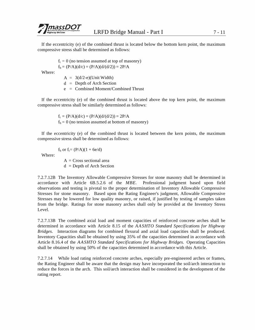
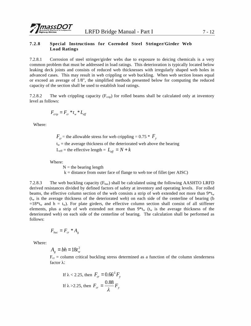
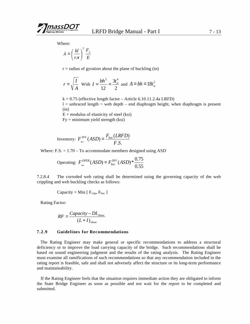
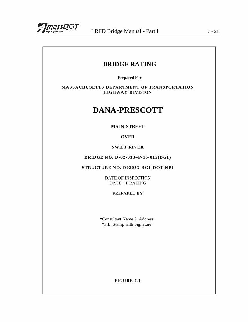
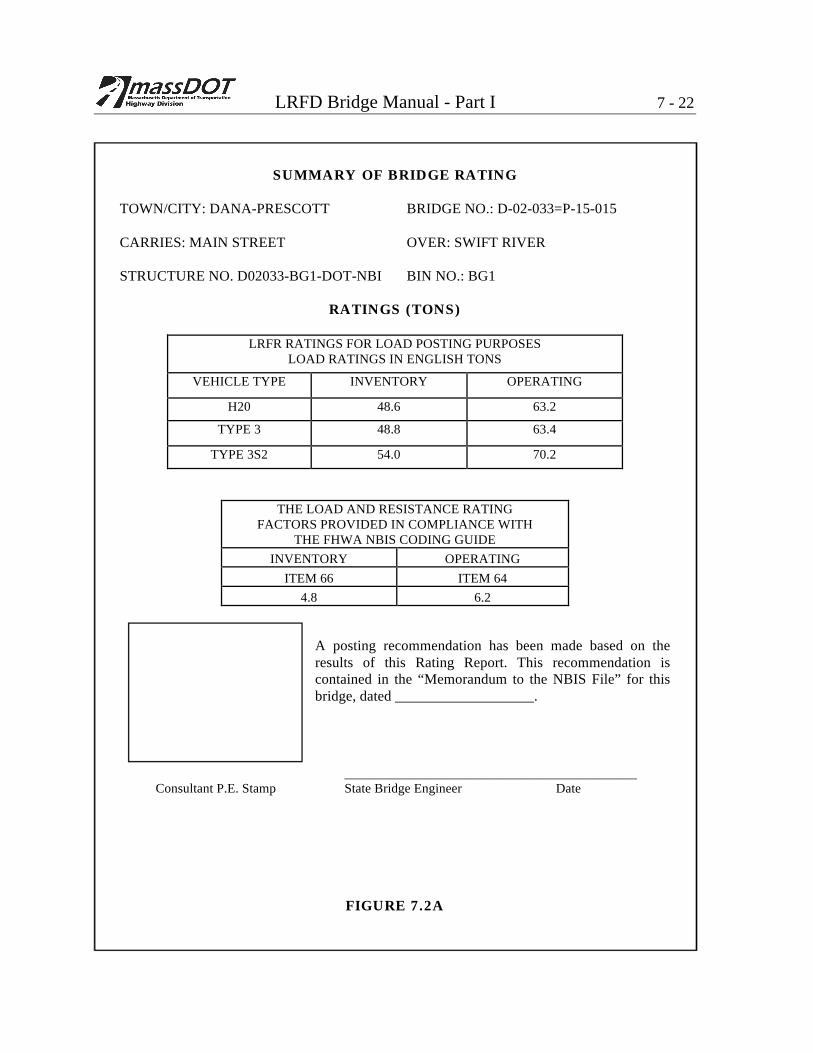
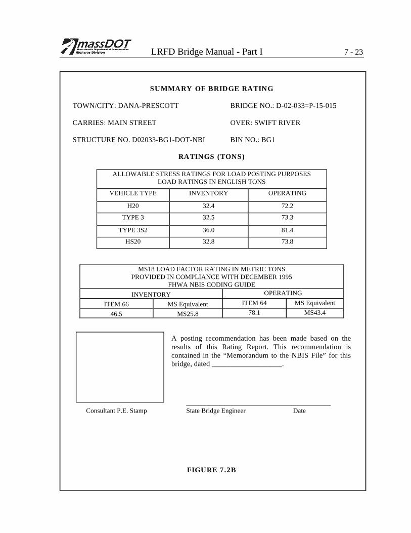
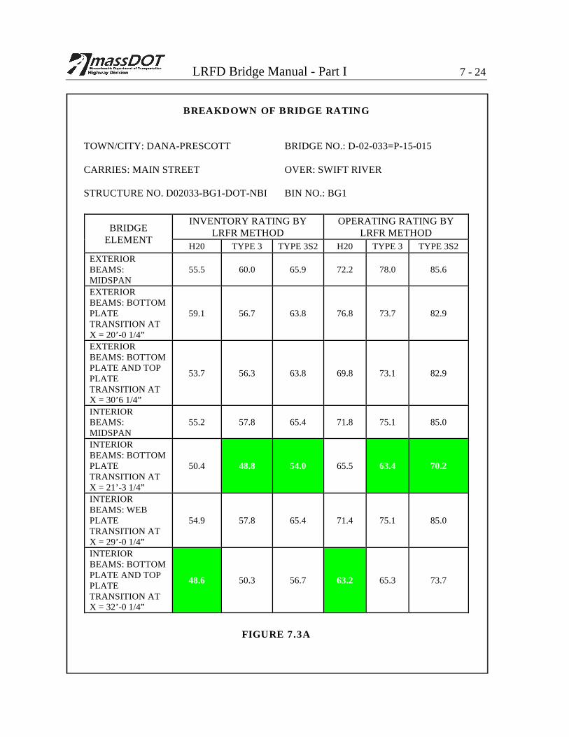
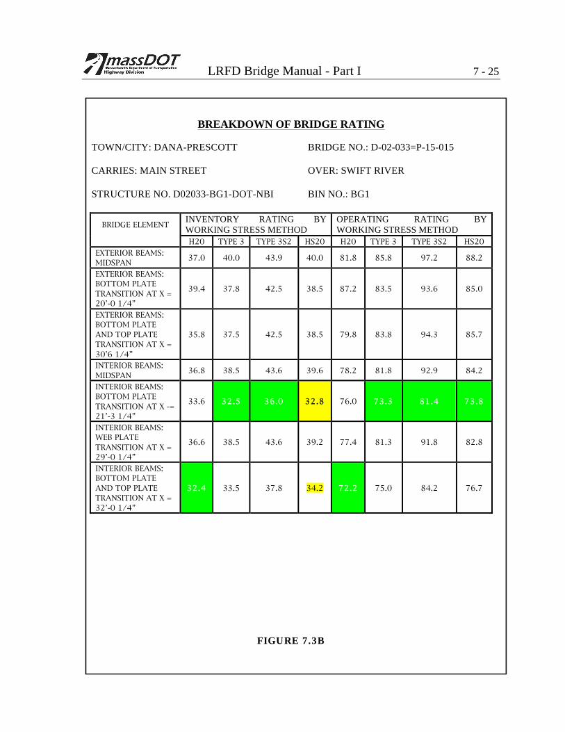
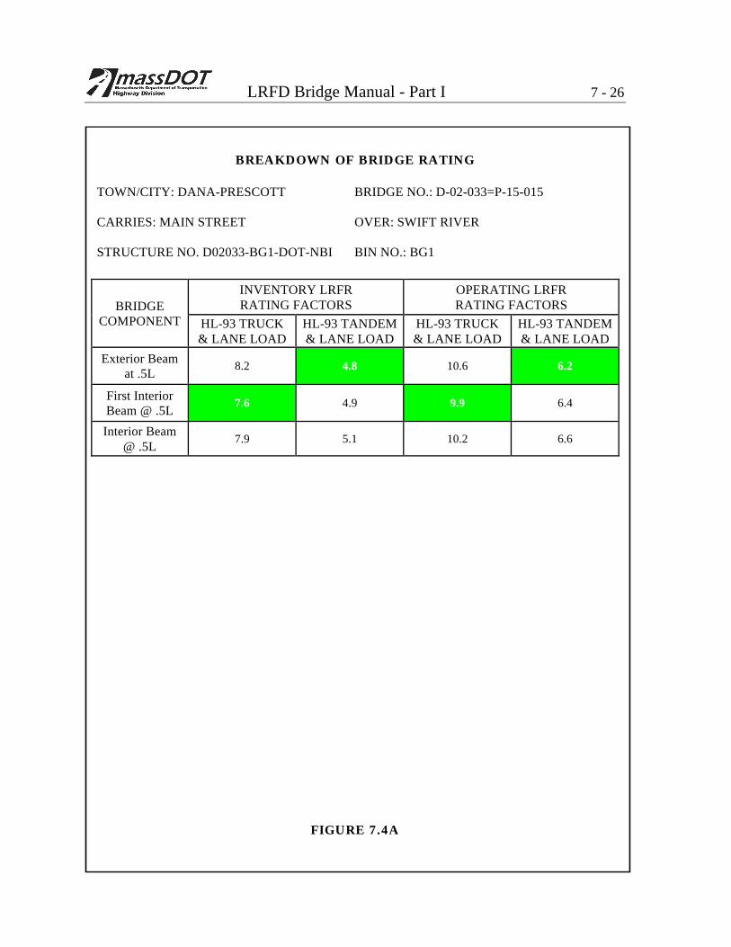
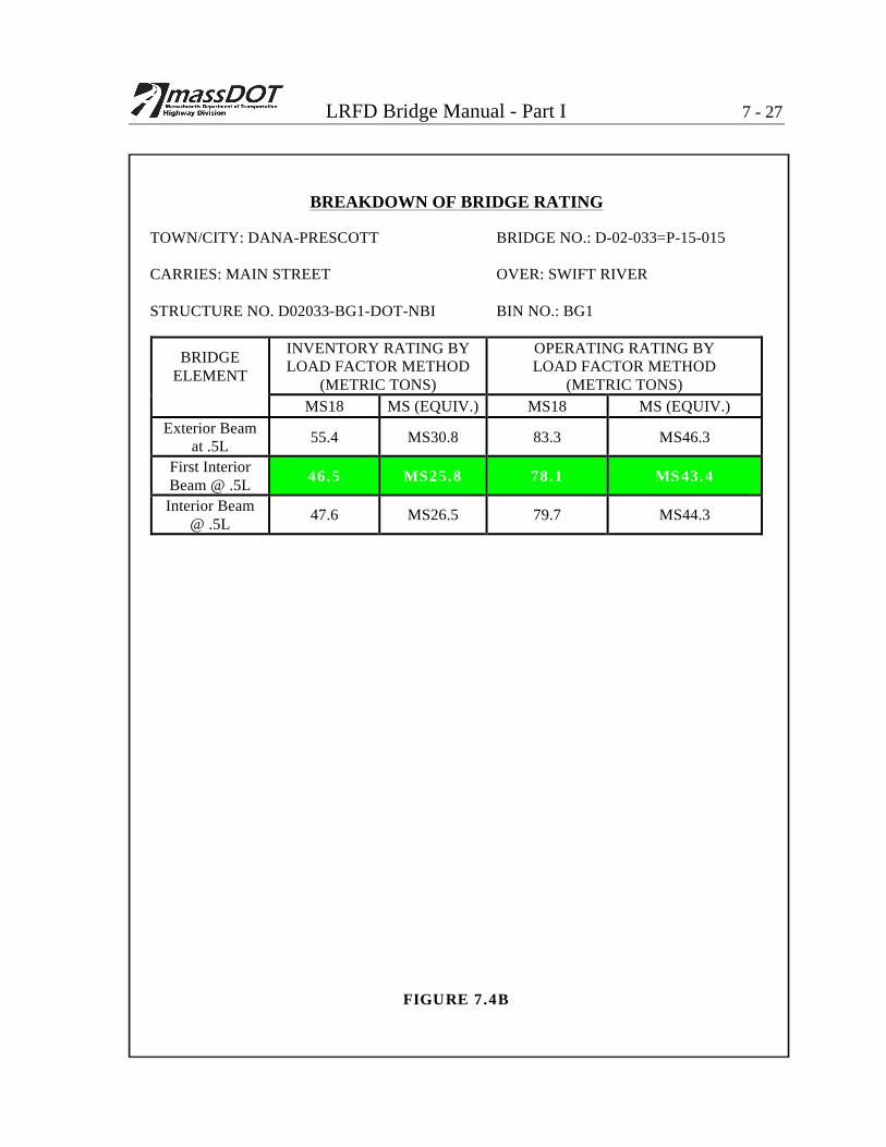
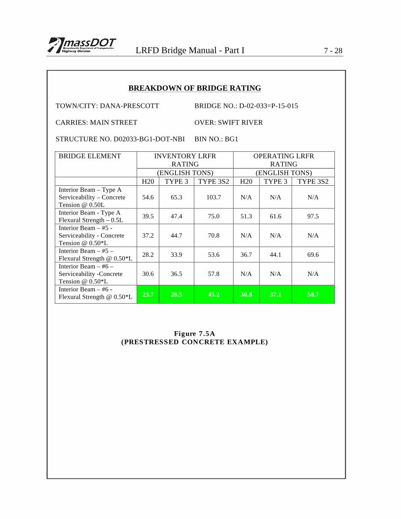
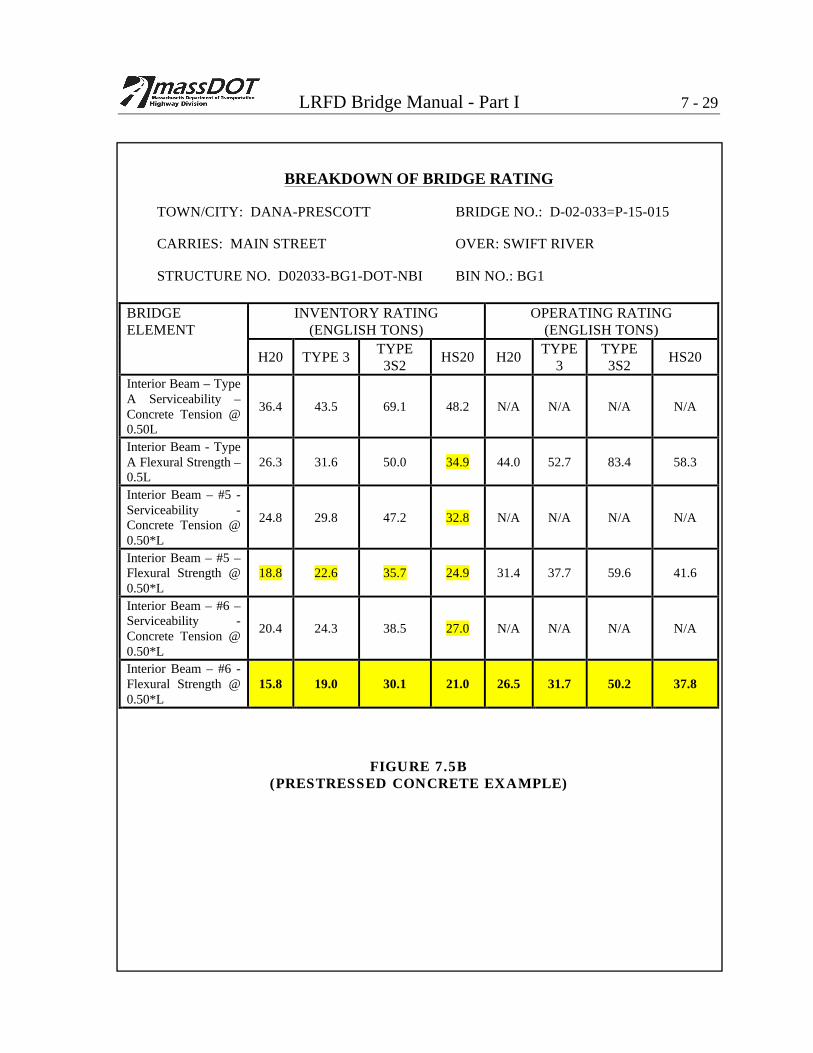
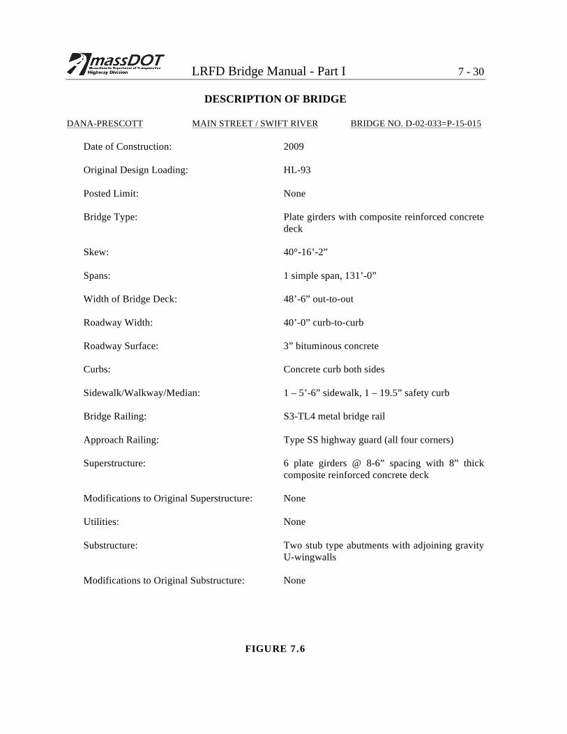
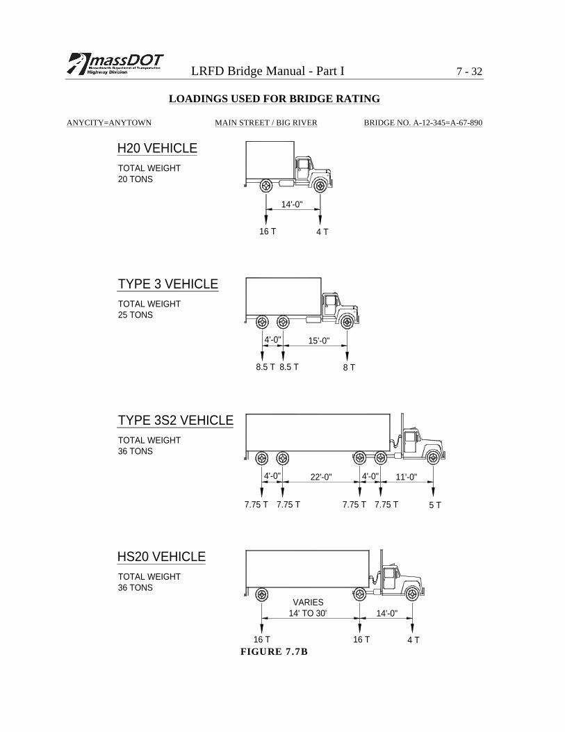
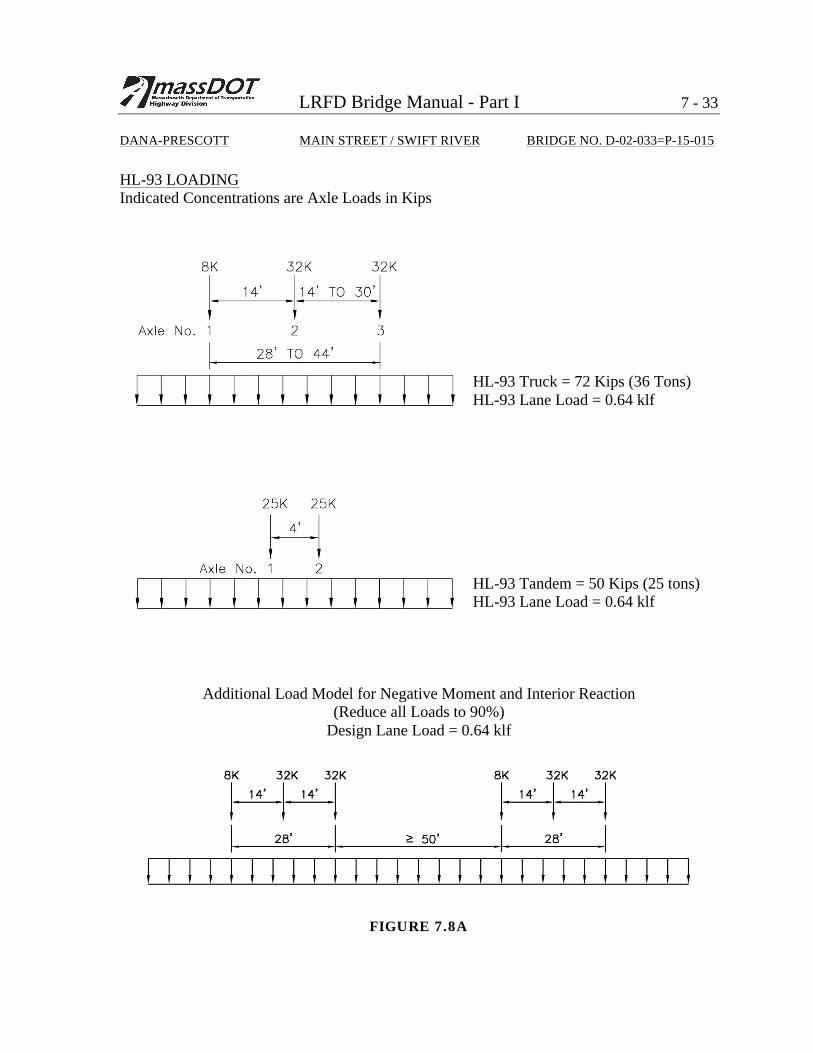