Embed Size (px)
Citation preview
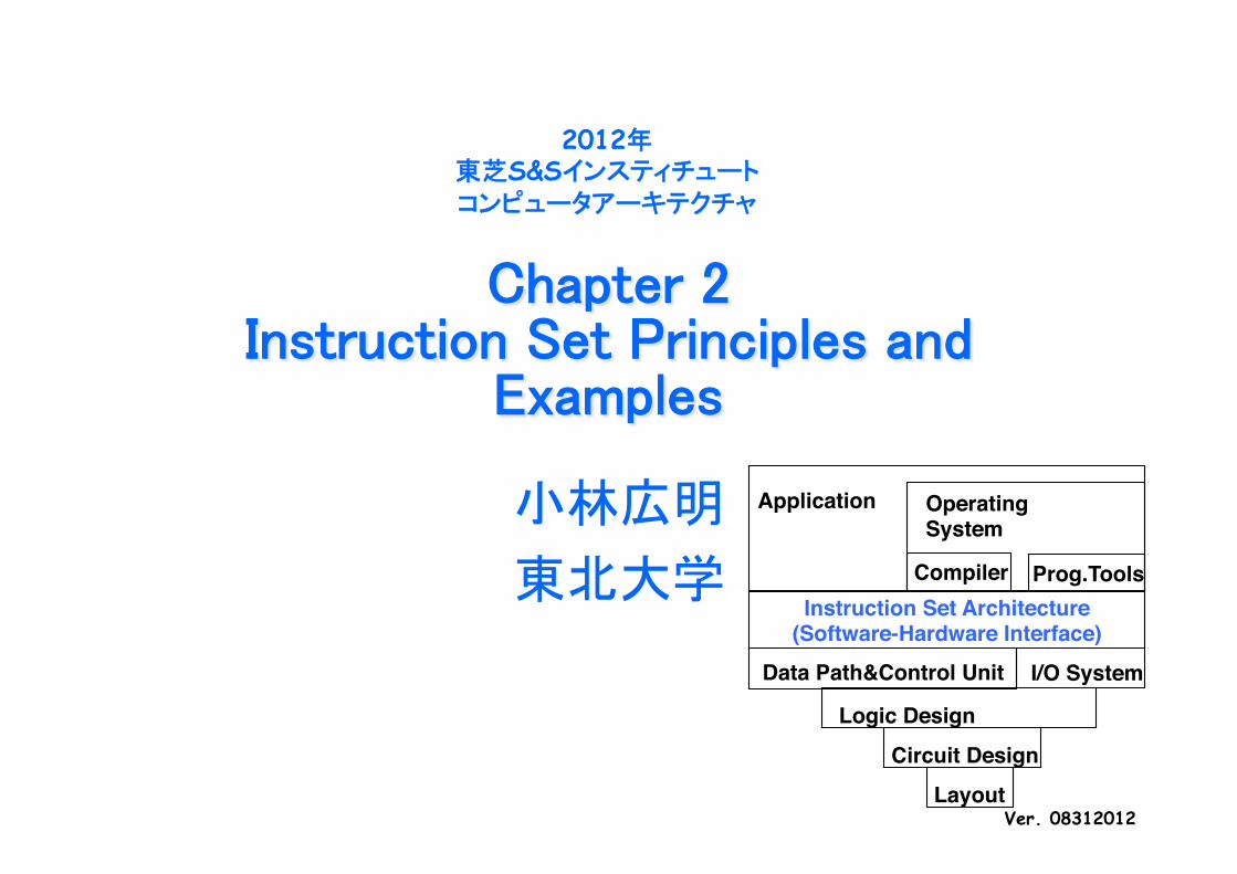
Chapter 2Instruction Set Principles and
Examples
小林広明 東北大学
2012年 東芝S&Sインスティチュート コンピュータアーキテクチャ
Ver. 08312012
Instruction Set Architecture!(Software-Hardware Interface) !
Data Path&Control Unit! I/O System!
Circuit Design!Logic Design!
Layout!
Prog.Tools!
Operating!System!
Application!
Compiler!
2012年 東芝S&Sインスティチュート コンピュータアーキテクチャ
東北大学 小林広明 2
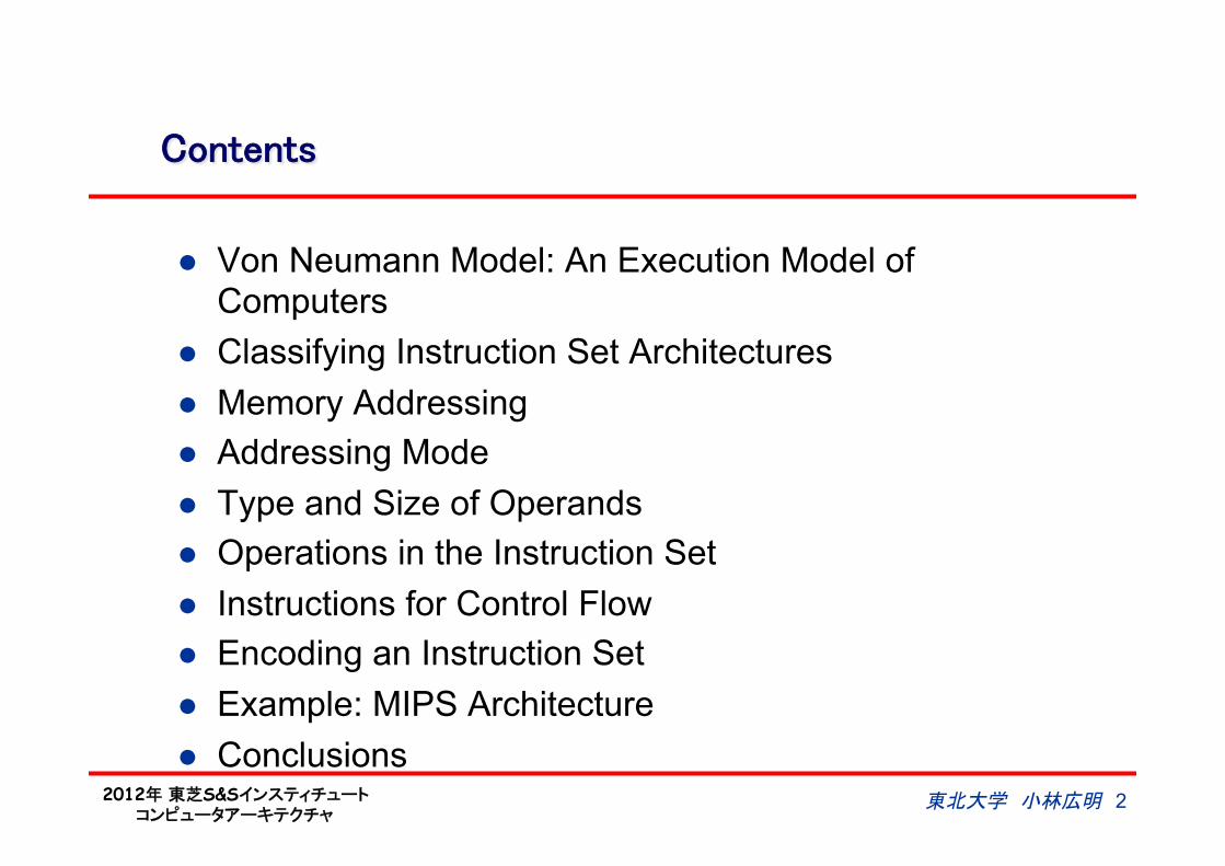
Contents
l Von Neumann Model: An Execution Model of Computers
l Classifying Instruction Set Architectures l Memory Addressing l Addressing Mode l Type and Size of Operands l Operations in the Instruction Set l Instructions for Control Flow l Encoding an Instruction Set l Example: MIPS Architecture l Conclusions
2012年 東芝S&Sインスティチュート コンピュータアーキテクチャ
3 東北大学 小林広明
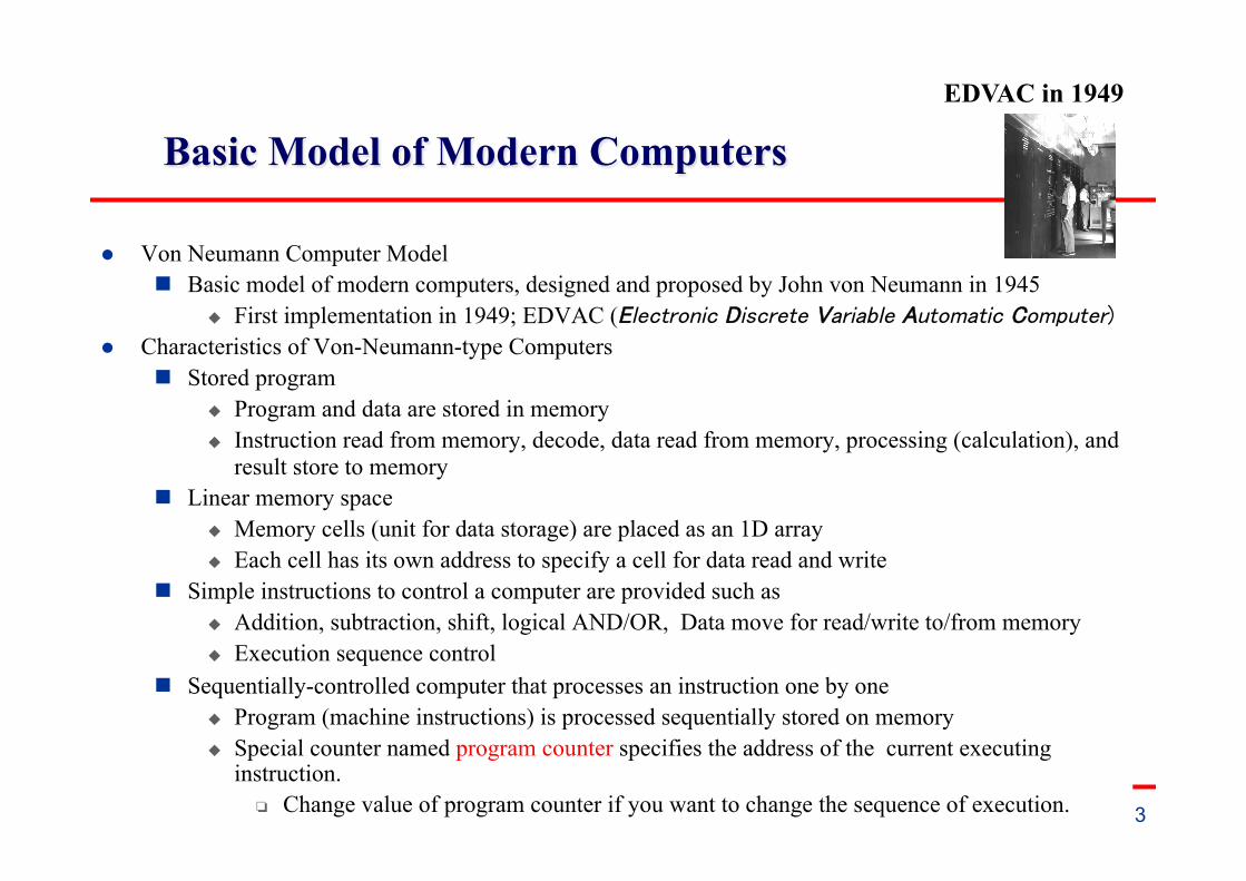
Basic Model of Modern Computers
l Von Neumann Computer Model n Basic model of modern computers, designed and proposed by John von Neumann in 1945
u First implementation in 1949; EDVAC (Electronic Discrete Variable Automatic Computer) l Characteristics of Von-Neumann-type Computers
n Stored program u Program and data are stored in memory u Instruction read from memory, decode, data read from memory, processing (calculation), and
result store to memory n Linear memory space
u Memory cells (unit for data storage) are placed as an 1D array u Each cell has its own address to specify a cell for data read and write
n Simple instructions to control a computer are provided such as u Addition, subtraction, shift, logical AND/OR, Data move for read/write to/from memory u Execution sequence control
n Sequentially-controlled computer that processes an instruction one by one u Program (machine instructions) is processed sequentially stored on memory u Special counter named program counter specifies the address of the current executing
instruction. Change value of program counter if you want to change the sequence of execution.
EDVAC in 1949
2012年 東芝S&Sインスティチュート コンピュータアーキテクチャ
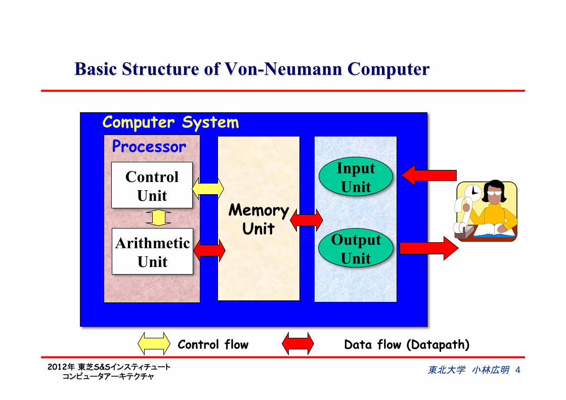
Basic Structure of Von-Neumann Computer
Control Unit
Arithmetic Unit
Memory Unit
Input Unit
Output Unit
Processor Computer System
Control flow Data flow (Datapath)
東北大学 小林広明 4
2012年 東芝S&Sインスティチュート コンピュータアーキテクチャ
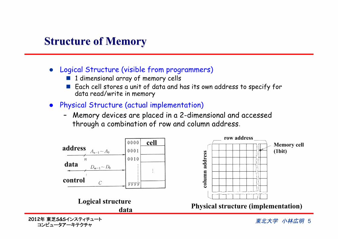
Structure of Memory
l Logical Structure (visible from programmers) n 1 dimensional array of memory cells n Each cell stores a unit of data and has its own address to specify for
data read/write in memory
Logical structure Physical structure (implementation)
l Physical Structure (actual implementation) – Memory devices are placed in a 2-dimensional and accessed
through a combination of row and column address.
address
data
data
control
cell row address
colu
mn
addr
ess
Memory cell (1bit)
東北大学 小林広明 5
2012年 東芝S&Sインスティチュート コンピュータアーキテクチャ
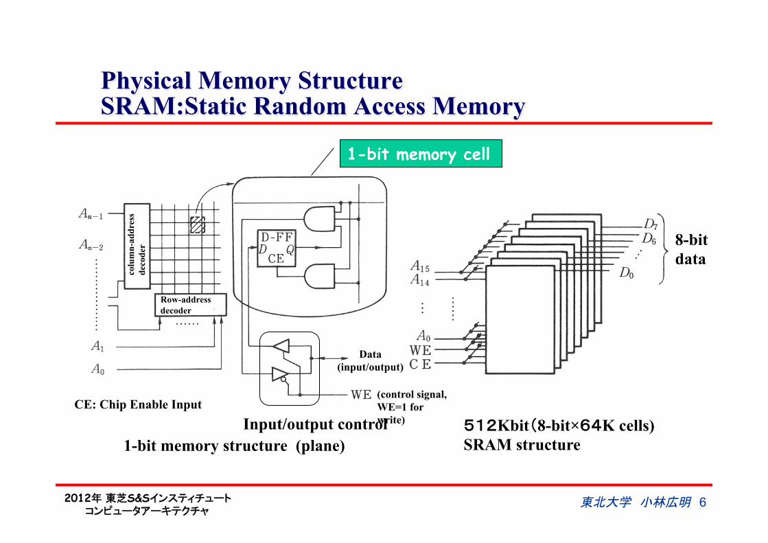
Physical Memory Structure SRAM:Static Random Access Memory
1-bit memory structure (plane) 512Kbit(8-bit×64K cells) SRAM structure
1-bit memory cell
8-bit data
Row-address decoder
colu
mn-
addr
ess
deco
der
Data (input/output)
Input/output control
(control signal, WE=1 for write)
CE: Chip Enable Input
東北大学 小林広明 6
2012年 東芝S&Sインスティチュート コンピュータアーキテクチャ
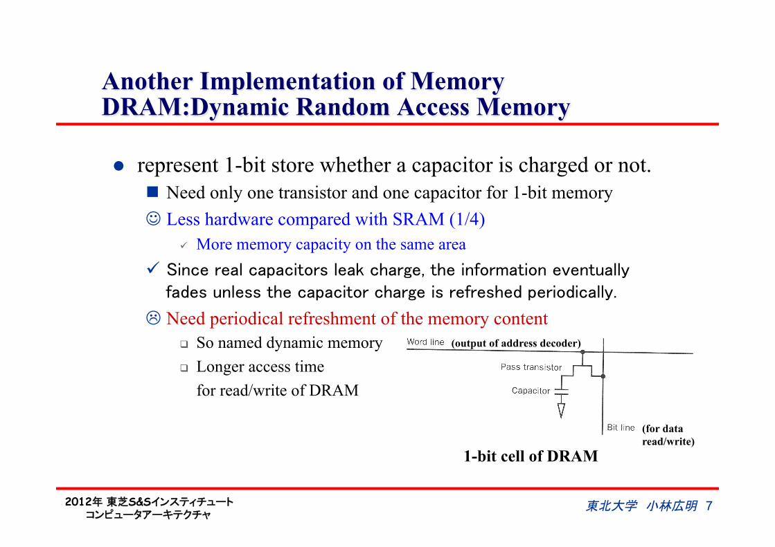
Another Implementation of Memory DRAM:Dynamic Random Access Memory
l represent 1-bit store whether a capacitor is charged or not. n Need only one transistor and one capacitor for 1-bit memory J Less hardware compared with SRAM (1/4)
ü More memory capacity on the same area"ü Since real capacitors leak charge, the information eventually
fades unless the capacitor charge is refreshed periodically. L Need periodical refreshment of the memory content
q So named dynamic memory q Longer access time for read/write of DRAM
1-bit cell of DRAM
(output of address decoder)
(for data read/write)
東北大学 小林広明 7
2012年 東芝S&Sインスティチュート コンピュータアーキテクチャ
DRAM Internal Structure
東北大学 小林広明 8
DIMM
2012年 東芝S&Sインスティチュート コンピュータアーキテクチャ
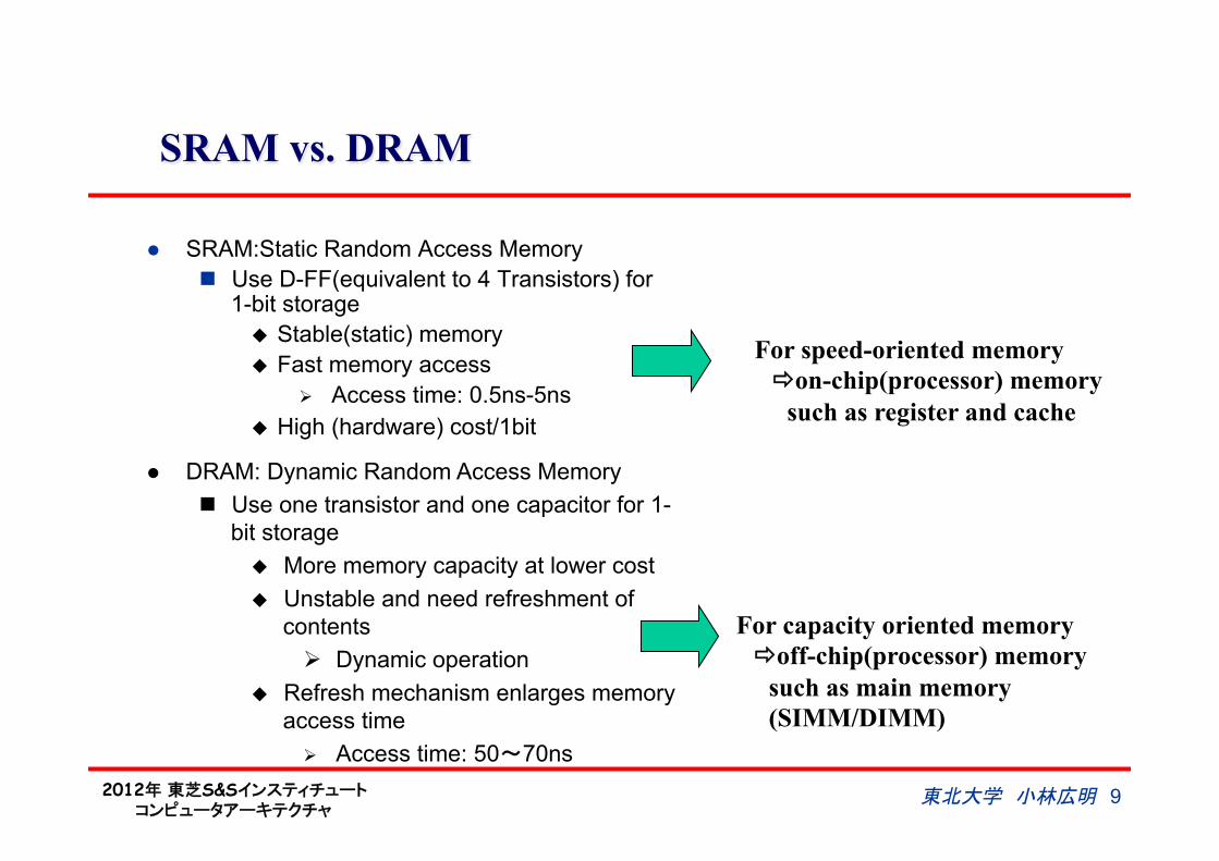
SRAM vs. DRAM
l SRAM:Static Random Access Memory n Use D-FF(equivalent to 4 Transistors) for
1-bit storage u Stable(static) memory u Fast memory access
Ø Access time: 0.5ns-5ns u High (hardware) cost/1bit
For speed-oriented memory ðon-chip(processor) memory such as register and cache
For capacity oriented memory ðoff-chip(processor) memory such as main memory (SIMM/DIMM)
l DRAM: Dynamic Random Access Memory n Use one transistor and one capacitor for 1-
bit storage u More memory capacity at lower cost u Unstable and need refreshment of
contents Ø Dynamic operation
u Refresh mechanism enlarges memory access time
Ø Access time: 50~70ns
東北大学 小林広明 9

2012年 東芝S&Sインスティチュート コンピュータアーキテクチャ
Basic Structure of Von-Neumann Computer
Control Unit
Arithmetic Unit
Memory Unit
Input Unit
Output Unit
Processor Computer System
Control flow Data flow (Datapath)
東北大学 小林広明 10
2012年 東芝S&Sインスティチュート コンピュータアーキテクチャ
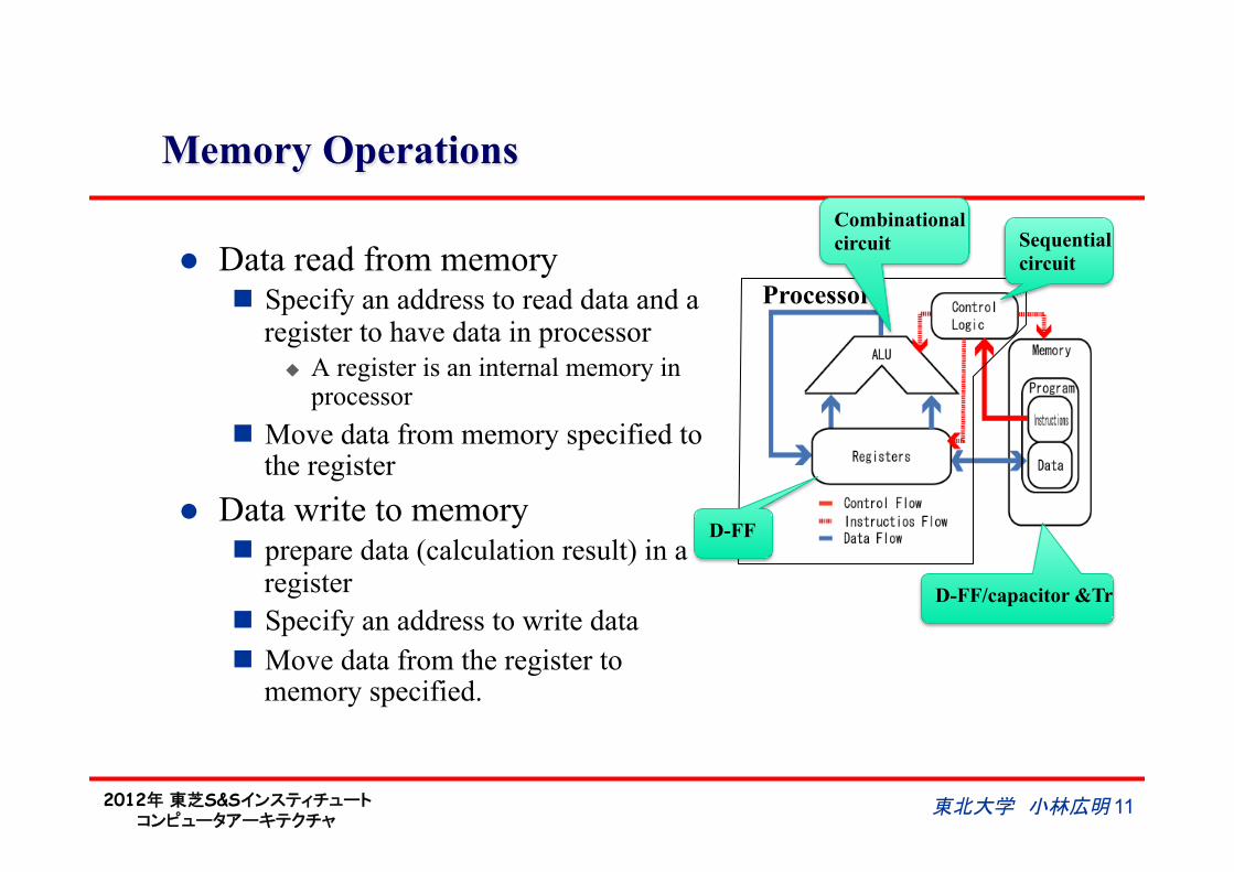
Memory Operations
l Data read from memory n Specify an address to read data and a
register to have data in processor u A register is an internal memory in
processor n Move data from memory specified to
the register l Data write to memory
n prepare data (calculation result) in a register
n Specify an address to write data n Move data from the register to
memory specified.
Processor
Sequential circuit
Combinational circuit
D-FF
D-FF/capacitor &Tr
東北大学 小林広明 11
2012年 東芝S&Sインスティチュート コンピュータアーキテクチャ
12 東北大学 小林広明
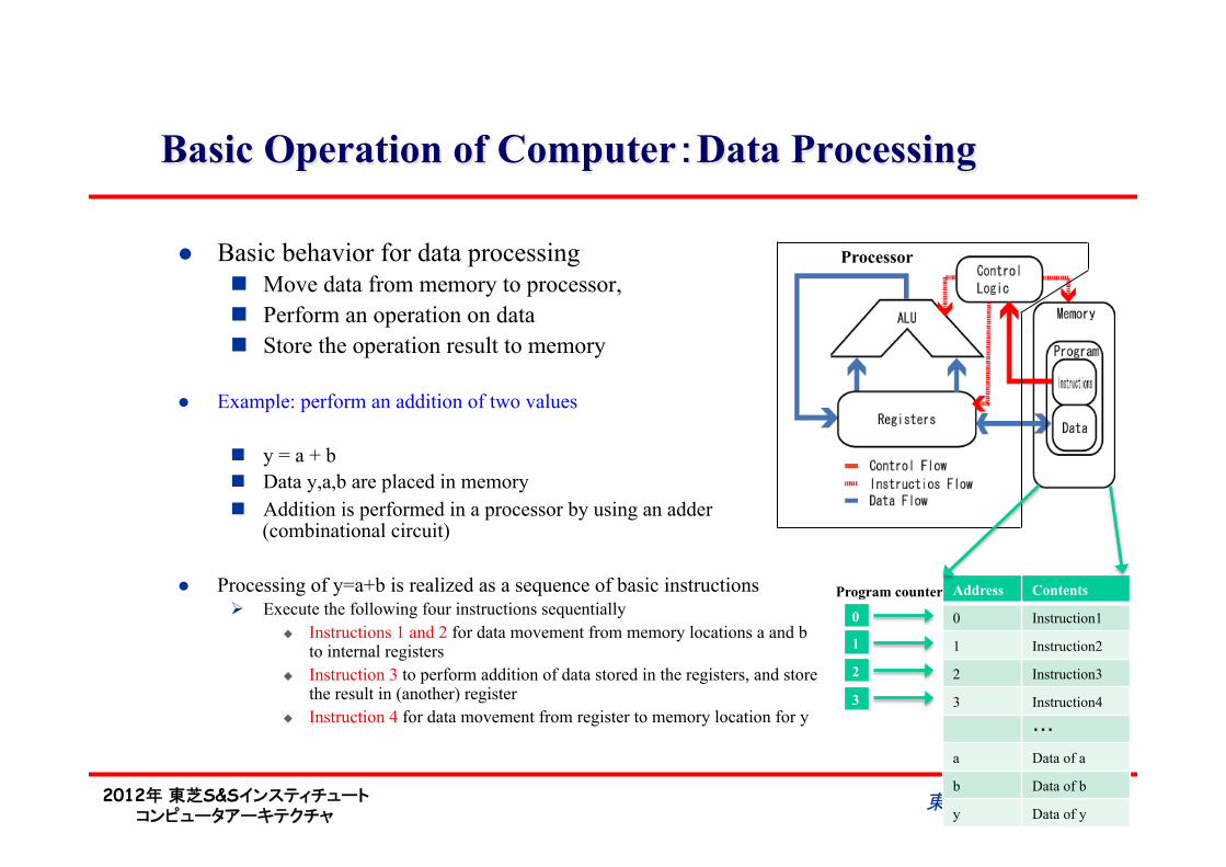
Basic Operation of Computer:Data Processing
l Basic behavior for data processing n Move data from memory to processor, n Perform an operation on data n Store the operation result to memory
l Example: perform an addition of two values
n y = a + b n Data y,a,b are placed in memory n Addition is performed in a processor by using an adder
(combinational circuit)
l Processing of y=a+b is realized as a sequence of basic instructions Ø Execute the following four instructions sequentially
u Instructions 1 and 2 for data movement from memory locations a and b to internal registers
u Instruction 3 to perform addition of data stored in the registers, and store the result in (another) register
u Instruction 4 for data movement from register to memory location for y
Processor
Address Contents
0 Instruction1
1 Instruction2
2 Instruction3
3 Instruction4
・・・
a Data of a
b Data of b
y Data of y
Program counter
0
1
2
3
2012年 東芝S&Sインスティチュート コンピュータアーキテクチャ
Sequential Processing: Basic Execution Control for Computer
1. Computer sequentially processes instructions in order of memory locations n Sequential processing n Current memory location of an instruction processed by computer
is hold by a program counter (PC) n Sequential processing is carried out by incrementing the content of
PC Ø Basic operations specified by instructions are: data movement to/
from memory, arithmetic operations 2. In addition, special instructions (named JUMP and BRANCH) for execution
control are prepared to change the order of instruction execution. n if…then…else n loop (iteration) n Action: change the content of PC to the destination address
specified by JUMP or BRANCH instruction
東北大学 小林広明 13
2012年 東芝S&Sインスティチュート コンピュータアーキテクチャ
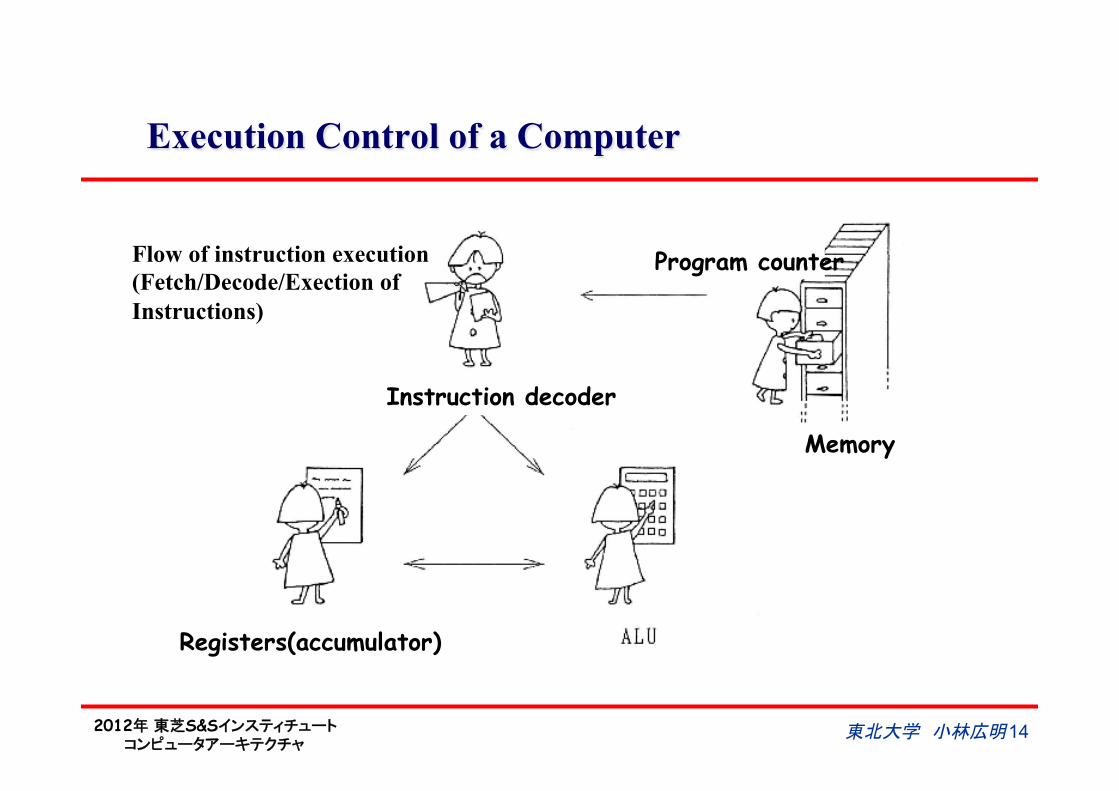
Execution Control of a Computer
Flow of instruction execution (Fetch/Decode/Exection of Instructions)
Instruction decoder
Program counter
Memory
Registers(accumulator)
東北大学 小林広明 14
2012年 東芝S&Sインスティチュート コンピュータアーキテクチャ
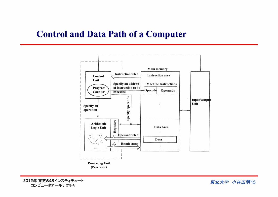
Control and Data Path of a Computer
Program Counter
Control Unit
Instruction fetch
Specify an address of instruction to be executed
Specify an operation
Arithmetic Logic Unit
Reg
iste
rs Sp
ecify
ope
rand
s
Operand fetch
Result store
Data Area
Data
Input/Output Unit
Opecode Operands
Machine Instructions
Instruction area
Main memory
Processing Unit (Processor)
東北大学 小林広明 15
2012年 東芝S&Sインスティチュート コンピュータアーキテクチャ
東北大学 小林広明 16
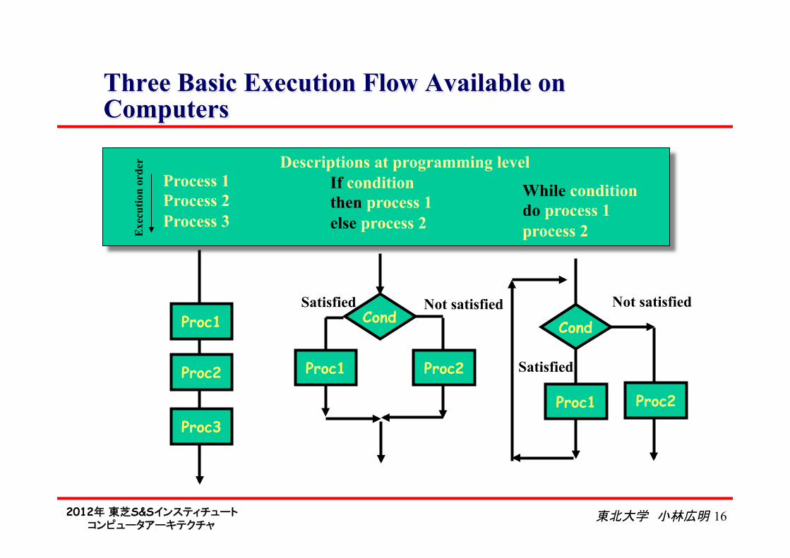
Three Basic Execution Flow Available on Computers
Cond
Proc1 Proc2
Proc1
Proc2
Proc3
Satisfied Not satisfied Cond
Proc1 Proc2
Satisfied
Not satisfied
If condition then process 1 else process 2
While condition do process 1 process 2
Process 1 Process 2 Process 3
Exe
cutio
n or
der Descriptions at programming level
2012年 東芝S&Sインスティチュート コンピュータアーキテクチャ
東北大学 小林広明 17
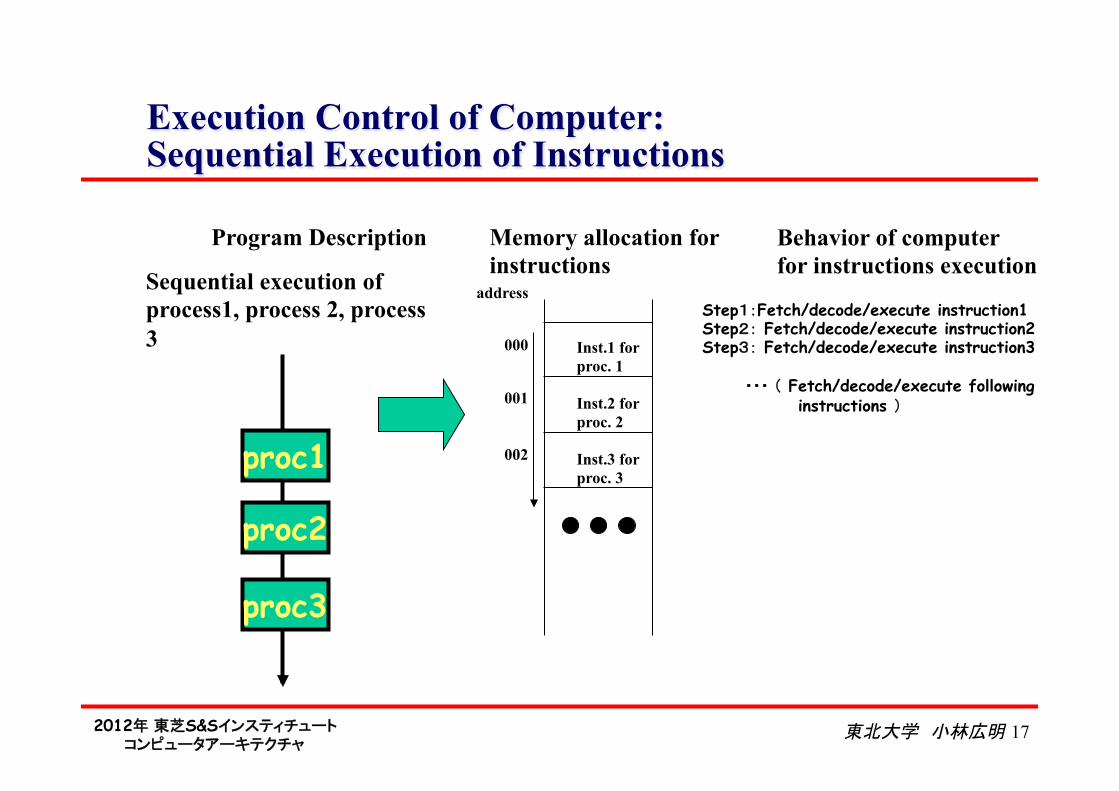
Execution Control of Computer: Sequential Execution of Instructions
proc1
proc2
proc3
Sequential execution of process1, process 2, process 3
Memory allocation for instructions
Inst.1 for proc. 1
Inst.2 for proc. 2
Inst.3 for proc. 3
address
000
001
002
Step1:Fetch/decode/execute instruction1 Step2: Fetch/decode/execute instruction2 Step3: Fetch/decode/execute instruction3 ・・・ ( Fetch/decode/execute following
instructions )
Program Description Behavior of computer for instructions execution
2012年 東芝S&Sインスティチュート コンピュータアーキテクチャ
東北大学 小林広明 18
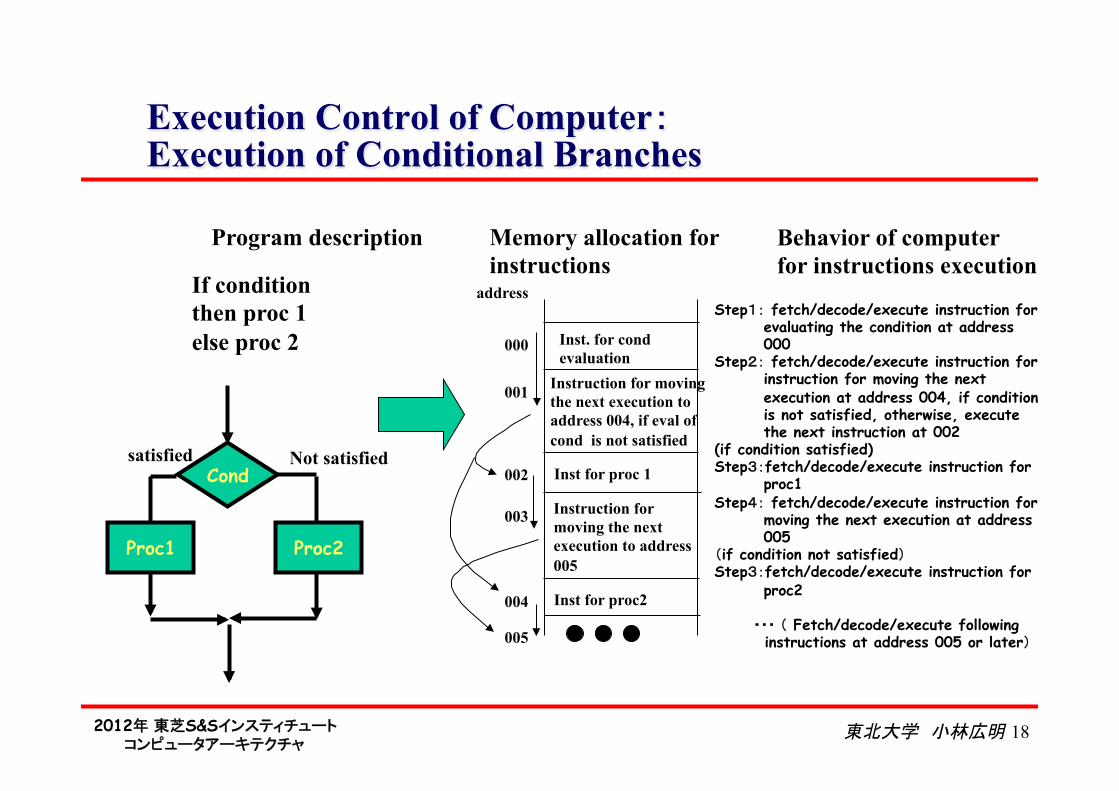
Execution Control of Computer: Execution of Conditional Branches
Memory allocation for instructions
Inst. for cond evaluation
Instruction for moving the next execution to address 004, if eval of cond is not satisfied
Inst for proc2
address
000
001
003
Step1: fetch/decode/execute instruction for evaluating the condition at address 000
Step2: fetch/decode/execute instruction for instruction for moving the next execution at address 004, if condition is not satisfied, otherwise, execute the next instruction at 002
(if condition satisfied) Step3:fetch/decode/execute instruction for
proc1 Step4: fetch/decode/execute instruction for
moving the next execution at address 005
(if condition not satisfied) Step3:fetch/decode/execute instruction for
proc2 ・・・ ( Fetch/decode/execute following
instructions at address 005 or later)
Program description Behavior of computer for instructions execution
Cond
Proc1 Proc2
satisfied Not satisfied
If condition then proc 1 else proc 2
Inst for proc 1 002
004
Instruction for moving the next execution to address 005
005
2012年 東芝S&Sインスティチュート コンピュータアーキテクチャ
東北大学 小林広明 19
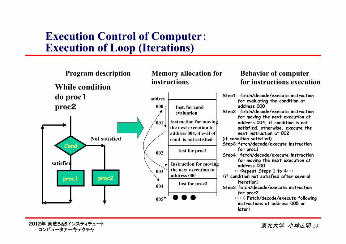
Execution Control of Computer: Execution of Loop (Iterations)
Memory allocation for instructions
Inst. for cond evaluation
Instruction for moving the next execution to address 004, if eval of cond is not satisfied
Inst for proc2
addres 000
001
003
Step1: fetch/decode/execute instruction for evaluating the condition at address 000
Step2: fetch/decode/execute instruction for moving the next execution at address 004, if condition is not satisfied, otherwise, execute the next instruction at 002
(if condition satisfied) Step3:fetch/decode/execute instruction
for proc1 Step4: fetch/decode/execute instruction
for moving the next execution at address 000
・・・Repeat Steps 1 to 4・・・ (if condition not satisfied after several
iteration) Step3:fetch/decode/execute instruction
for proc2 ・・・ ( Fetch/decode/execute following
instructions at address 005 or later)
Program description Behavior of computer for instructions execution
satisfied
Not satisfied Inst for proc1 002
Cond
proc1 proc2
While condition do proc1 proc2
Instruction for moving the next execution to address 000
004
005
2012年 東芝S&Sインスティチュート コンピュータアーキテクチャ
東北大学 小林広明 20
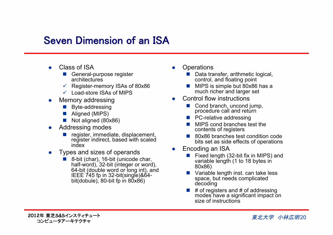
Seven Dimension of an ISA
l Class of ISA n General-purpose register
architectures ü Register-memory ISAs of 80x86 ü Load-store ISAs of MIPS
l Memory addressing n Byte-addressing n Aligned (MIPS) n Not aligned (80x86)
l Addressing modes n register, immediate, displacement,
register indirect, based with scaled index
l Types and sizes of operands n 8-bit (char), 16-bit (unicode char,
half-word), 32-bit (integer or word), 64-bit (double word or long int), and IEEE 745 fp in 32-bit(single)&64-bit(dobule), 80-bit fp in 80x86)
l Operations n Data transfer, arithmetic logical,
control, and floating point n MIPS is simple but 80x86 has a
much richer and larger set l Control flow instructions
n Cond branch, uncond jump, procedure call and return
n PC-relative addressing n MIPS cond branches test the
contents of registers n 80x86 branches test condition code
bits set as side effects of operations l Encoding an ISA
n Fixed length (32-bit fix in MIPS) and variable length (1 to 18 bytes in 80x86)
n Variable length inst. can take less space, but needs complicated decoding
n # of registers and # of addressing modes have a significant impact on size of instructions
2012年 東芝S&Sインスティチュート コンピュータアーキテクチャ
東北大学 小林広明 21
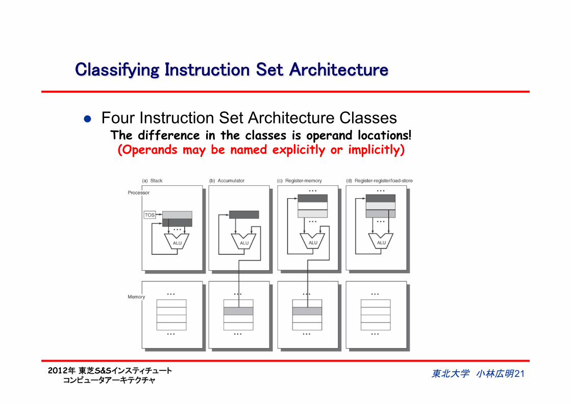
Classifying Instruction Set Architecture
l Four Instruction Set Architecture Classes The difference in the classes is operand locations! (Operands may be named explicitly or implicitly)
2012年 東芝S&Sインスティチュート コンピュータアーキテクチャ
東北大学 小林広明 22
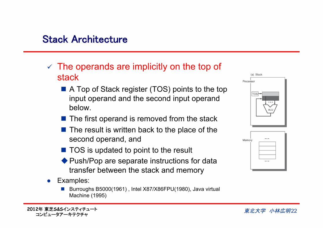
Stack Architecture
ü The operands are implicitly on the top of stack n A Top of Stack register (TOS) points to the top
input operand and the second input operand below.
n The first operand is removed from the stack n The result is written back to the place of the
second operand, and n TOS is updated to point to the result u Push/Pop are separate instructions for data
transfer between the stack and memory l Examples:
n Burroughs B5000(1961) , Intel X87/X86FPU(1980), Java virtual Machine (1995)
2012年 東芝S&Sインスティチュート コンピュータアーキテクチャ
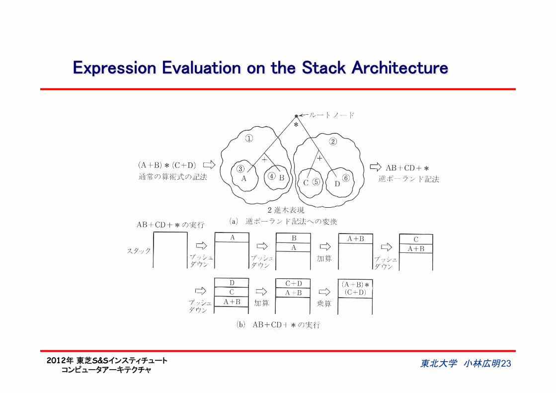
Expression Evaluation on the Stack Architecture
東北大学 小林広明 23
2012年 東芝S&Sインスティチュート コンピュータアーキテクチャ
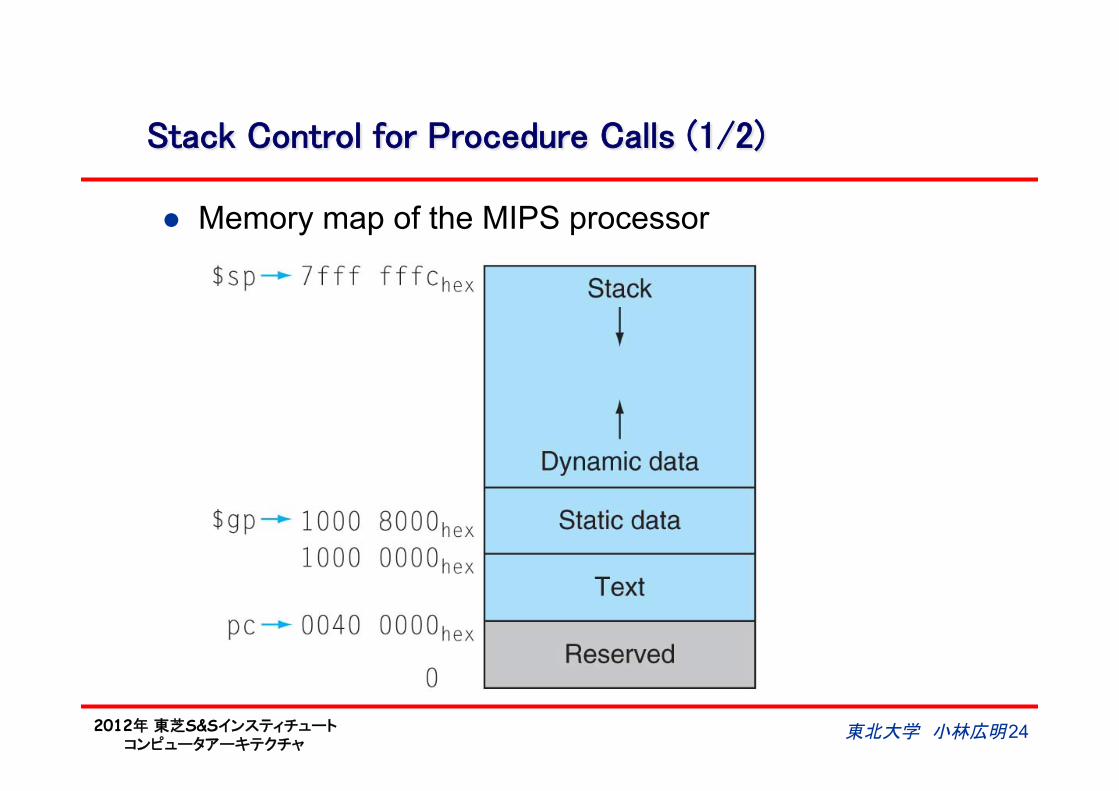
Stack Control for Procedure Calls (1/2)
l Memory map of the MIPS processor
東北大学 小林広明 24
2012年 東芝S&Sインスティチュート コンピュータアーキテクチャ
Stack Control for Procedure Calls (2/2)
東北大学 小林広明 25
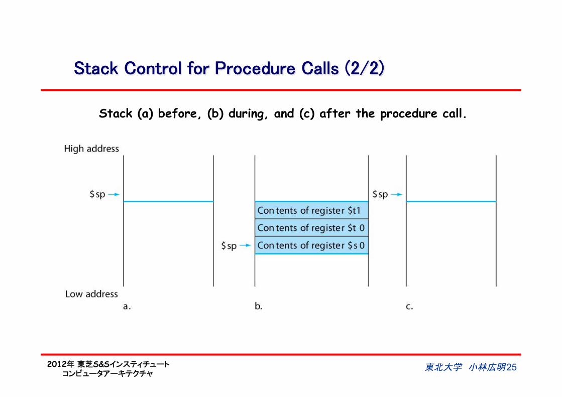
Stack (a) before, (b) during, and (c) after the procedure call.
2012年 東芝S&Sインスティチュート コンピュータアーキテクチャ
東北大学 小林広明 26
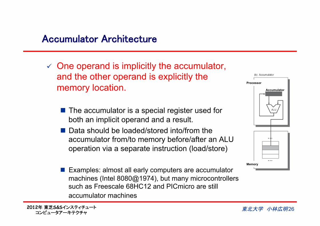
Accumulator Architecture
ü One operand is implicitly the accumulator, and the other operand is explicitly the memory location.
n The accumulator is a special register used for both an implicit operand and a result.
n Data should be loaded/stored into/from the accumulator from/to memory before/after an ALU operation via a separate instruction (load/store)
n Examples: almost all early computers are accumulator machines (Intel 8080@1974), but many microcontrollers such as Freescale 68HC12 and PICmicro are still accumulator machines
Processor
Accumulator
Memory
2012年 東芝S&Sインスティチュート コンピュータアーキテクチャ
東北大学 小林広明 27
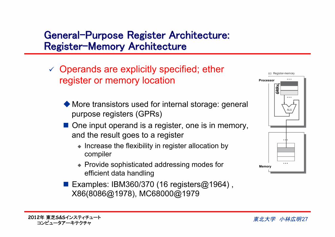
General-Purpose Register Architecture:Register-Memory Architecture
ü Operands are explicitly specified; ether register or memory location
u More transistors used for internal storage: general purpose registers (GPRs)
n One input operand is a register, one is in memory, and the result goes to a register
u Increase the flexibility in register allocation by compiler
u Provide sophisticated addressing modes for efficient data handling
n Examples: IBM360/370 (16 registers@1964) , X86(8086@1978), MC68000@1979
GRRs
Processor
Memory
2012年 東芝S&Sインスティチュート コンピュータアーキテクチャ
東北大学 小林広明 28
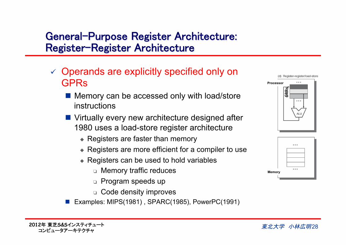
General-Purpose Register Architecture:Register-Register Architecture
ü Operands are explicitly specified only on GPRs n Memory can be accessed only with load/store
instructions n Virtually every new architecture designed after
1980 uses a load-store register architecture u Registers are faster than memory u Registers are more efficient for a compiler to use u Registers can be used to hold variables
Memory traffic reduces Program speeds up Code density improves
n Examples: MIPS(1981) , SPARC(1985), PowerPC(1991)
GRRs
Processor
Memory
2012年 東芝S&Sインスティチュート コンピュータアーキテクチャ
29
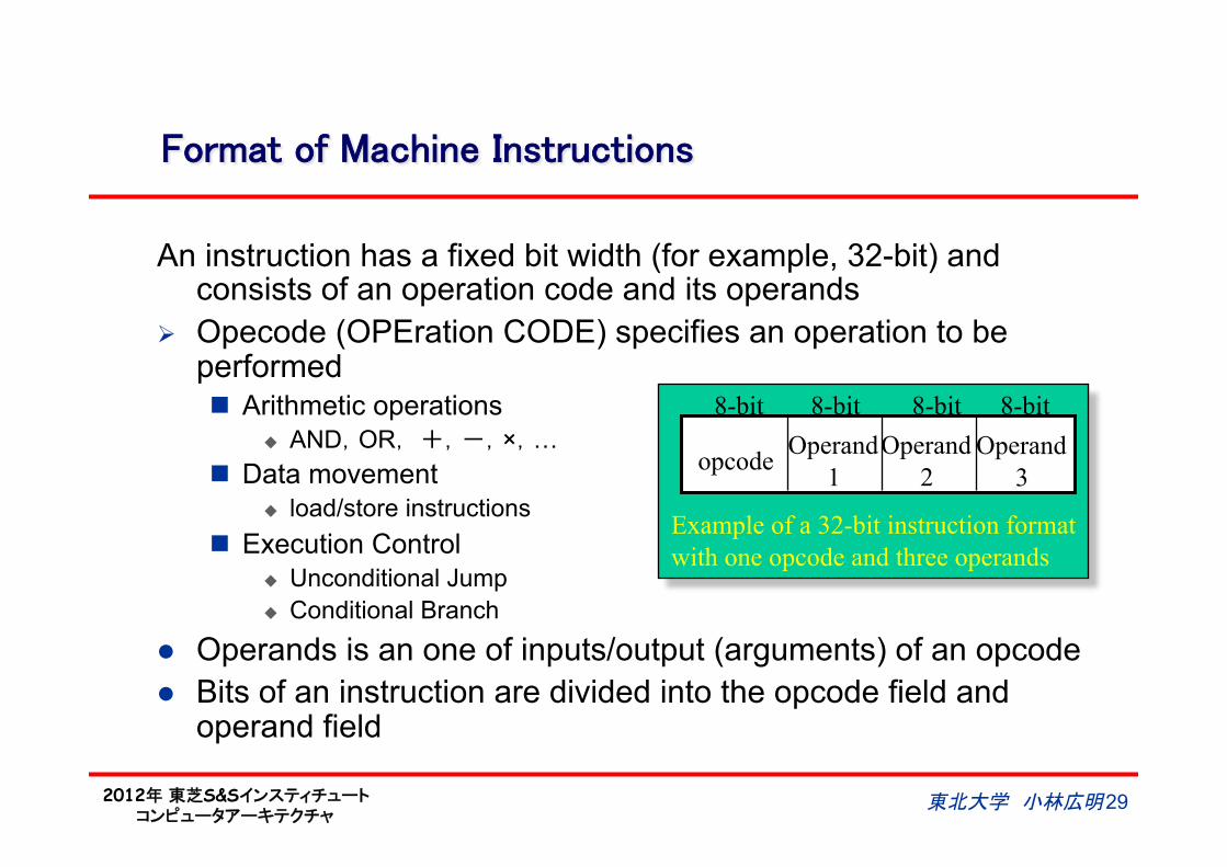
Format of Machine Instructions
An instruction has a fixed bit width (for example, 32-bit) and consists of an operation code and its operands
Ø Opecode (OPEration CODE) specifies an operation to be performed n Arithmetic operations
u AND,OR, +,-,×,… n Data movement
u load/store instructions n Execution Control
u Unconditional Jump u Conditional Branch
l Operands is an one of inputs/output (arguments) of an opcode l Bits of an instruction are divided into the opcode field and
operand field
東北大学 小林広明
opcode Operand
1
Operand
2
Operand
3
Example of a 32-bit instruction format
with one opcode and three operands
8-bit 8-bit 8-bit 8-bit
2012年 東芝S&Sインスティチュート コンピュータアーキテクチャ
30
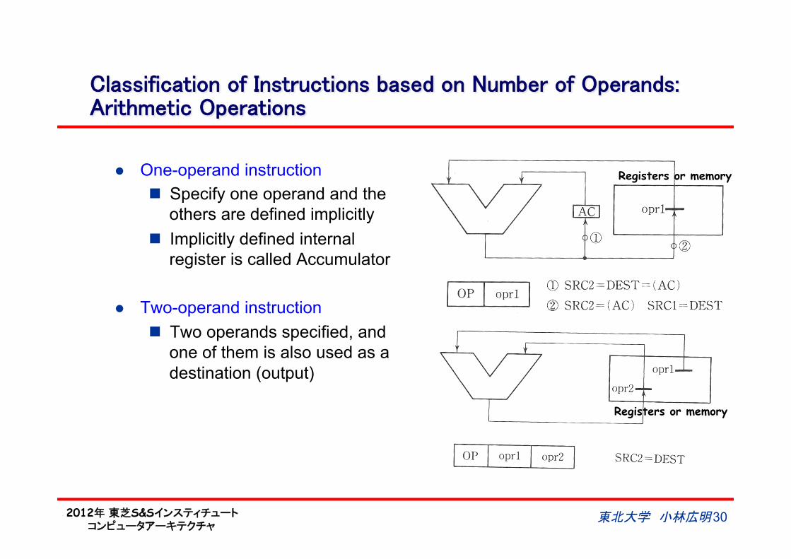
Classification of Instructions based on Number of Operands:Arithmetic Operations
l One-operand instruction n Specify one operand and the
others are defined implicitly n Implicitly defined internal
register is called Accumulator
l Two-operand instruction n Two operands specified, and
one of them is also used as a destination (output)
Registers or memory
Registers or memory
東北大学 小林広明
2012年 東芝S&Sインスティチュート コンピュータアーキテクチャ
31
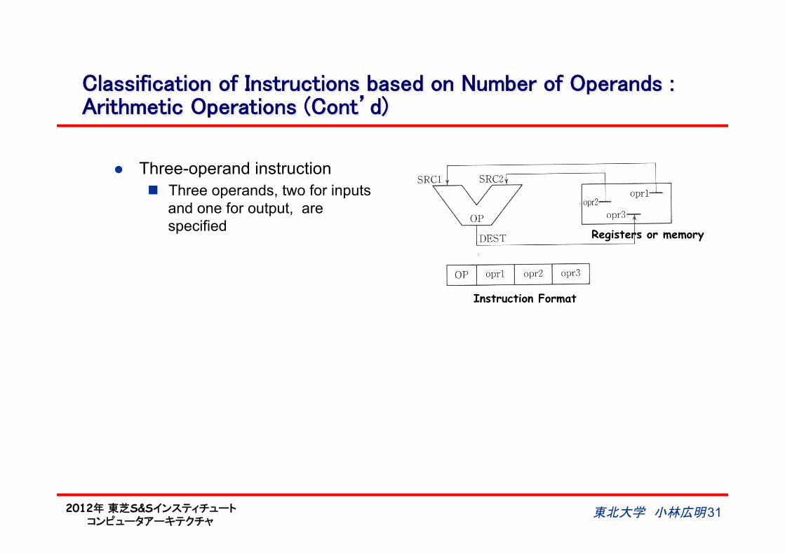
Classification of Instructions based on Number of Operands :Arithmetic Operations (Cont’d)
l Three-operand instruction n Three operands, two for inputs
and one for output, are specified Registers or memory
Instruction Format
東北大学 小林広明
2012年 東芝S&Sインスティチュート コンピュータアーキテクチャ
東北大学 小林広明 32
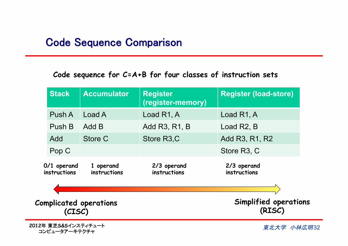
Code Sequence Comparison
Stack Accumulator Register (register-memory)
Register (load-store)
Push A Load A Load R1, A Load R1, A
Push B Add B Add R3, R1, B Load R2, B
Add Store C Store R3,C Add R3, R1, R2
Pop C Store R3, C
Code sequence for C=A+B for four classes of instruction sets
0/1 operand instructions
1 operand instructions
2/3 operand instructions
2/3 operand instructions
Complicated operations (CISC)
Simplified operations (RISC)
2012年 東芝S&Sインスティチュート コンピュータアーキテクチャ
CISC vs. RISC
l CISC: Complex Instruction Set Computer n Has rich instruction sets and is designed to simplify compilation of
high-level languages u Narrowing the gap between high-level languages and machine
instruction u Optimizing code size because compiled programs were often too
large for available memories in 1970s ~ 1980s u IBM 360/370, VAX-11/780, Intel X86 ISA
l RISC: Reduced Instruction Set Computer (1980~) n Has commonly used instructions only and make them fast in
execution. u Make common case fast and keep the system simple
Rarely executed instructions slow the entire control of the system The increase in memory size on computers eliminated the code
size problems arising from high-level languages and enabled operating systems to be written in high-level languages
u Simple instructions and their fixed size and format make pipelining much more efficient, running at higher frequency.
u Intel Xeon (Internal translation from X86 inst. to risc-ops), MIPS, SPARC, PowerPC, PA-RISC, DEC Alpha, ARM, SuperH…
東北大学 小林広明 33
2012年 東芝S&Sインスティチュート コンピュータアーキテクチャ
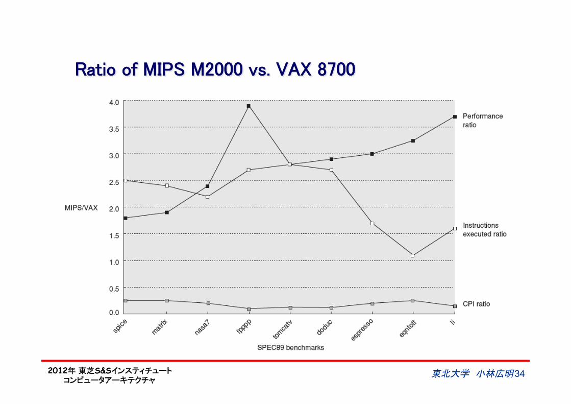
Ratio of MIPS M2000 vs. VAX 8700
東北大学 小林広明 34
2012年 東芝S&Sインスティチュート コンピュータアーキテクチャ
東北大学 小林広明 35
Comparison of GPR Architectures
Number of memory addresses
Maximum number of operands allowed
Type of Architecture Examples
0 3 Load-store Alpha, ARM, MIPS, PowerPC, SPARC, SuperH
1 2 Register-memory IBM 360/370, Intel X86, Motorola 68000, TI TMS320C54x
2 2 Memory-memory VAX (also has three-operand format)
3 3 Memory-memory VAX (also has two-operand format)
Type Advantages Disadvantages
Register-register (0,3)
Simple, fixed-length instruction encoding Simple code generation model. Instructions take similar number of clocks to execute
Higher instruction count than others. More instructions and lower instruction density leads to larger program.
Register-memory(1,2)
Data can be accessed without a separate load instruction first. Instruction format tends to be easy to encode and yields good density.
Operands are not equivalent since a source operand in a binary operation is destroyed. Encoding a register number and a memory address in each instruction may restrict the number of registers Clocks per instruction vary by operand location.
Memory-memory (2,2) or (3,3)
Most compact. Doesn’t waste registers for temporaries.
Large variation in instruction size, especially for three-operand instructions. In addition, large variation in work per instruction. Memory accesses create memory bottleneck. (not used today)
2012年 東芝S&Sインスティチュート コンピュータアーキテクチャ
Memory Addressing: How Instructions and Data are Placed in the Memory
東北大学 小林広明 36
• MIPS uses fixed size instructions (4-byte width), its memory addressing is Byte-addressed and Aligned.
• X86 uses variable size instructions (1-byte to 17-byte width), its memory addressing is Byte-addressed but Not Aligned.

2012年 東芝S&Sインスティチュート コンピュータアーキテクチャ
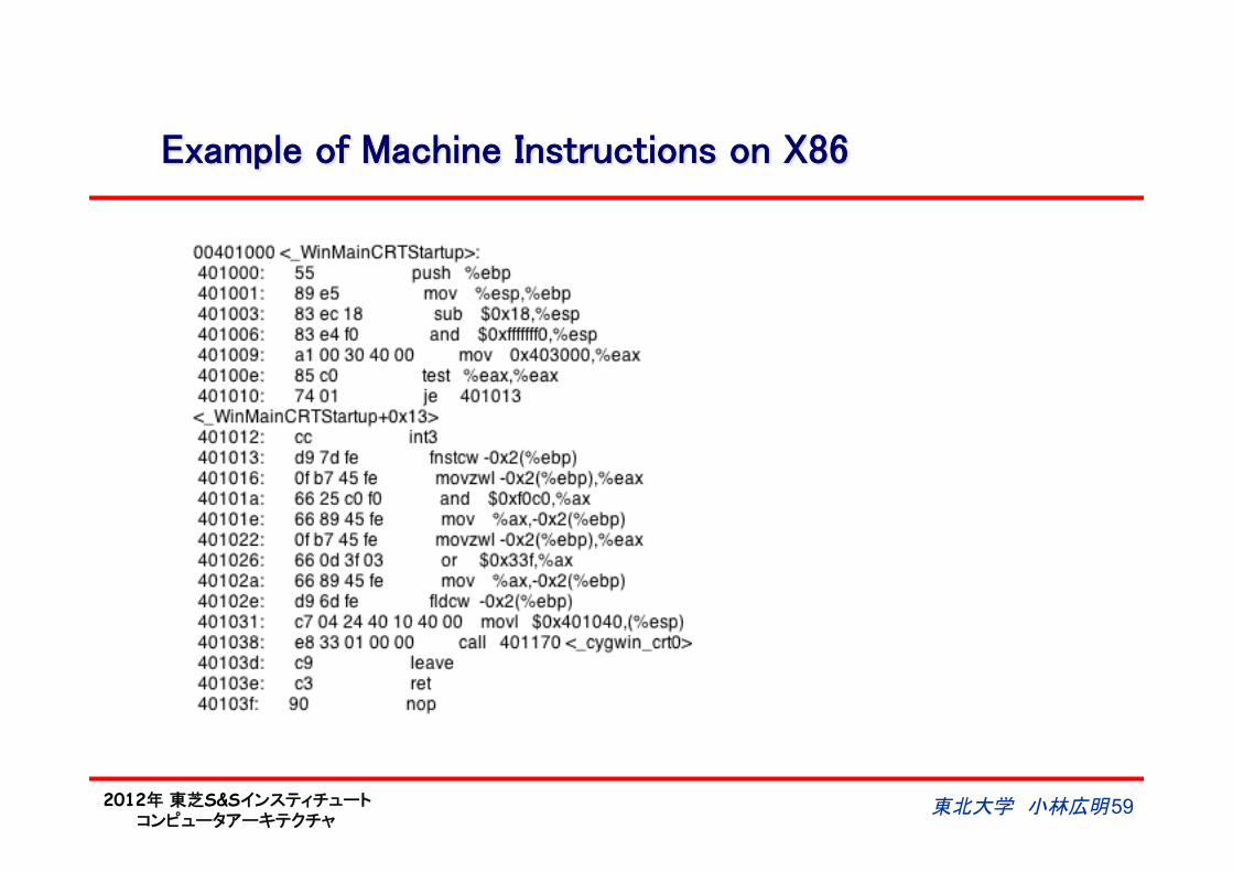
Example of Machine Instructions on X86
東北大学 小林広明 37
2012年 東芝S&Sインスティチュート コンピュータアーキテクチャ
Endianness: Big-Endian vs. Little-Endian (1/2)
l Endianness: the ordering of individually addressable sub-units (words, bytes, or even bits) within a longer data word stored in external memory. n How a 16-, 32- or 64-bit word (multi-byte data) is stored in a byte-addressed
memory??? l Big-Endian: Most significant byte first
n MC6800/68000, PowerPC, IBM System/370, SPARC(until version 9) , JAVA VM
l Little-Endian: Least significant byte first n x86, 6502, Z80, VAX
l Bi-Endian: switchable endianness n ARM, PowerPC, Alpha, SPARC V9, MIPS, PA-RISC, IA-64, Crusoe
東北大学 小林広明 38
2012年 東芝S&Sインスティチュート コンピュータアーキテクチャ
Endianness: Big-Endian vs. Little-Endian (2/2)
東北大学 小林広明 39
Output on a big-endian machine Output on a little-endian machine
2012年 東芝S&Sインスティチュート コンピュータアーキテクチャ
東北大学 小林広明 40
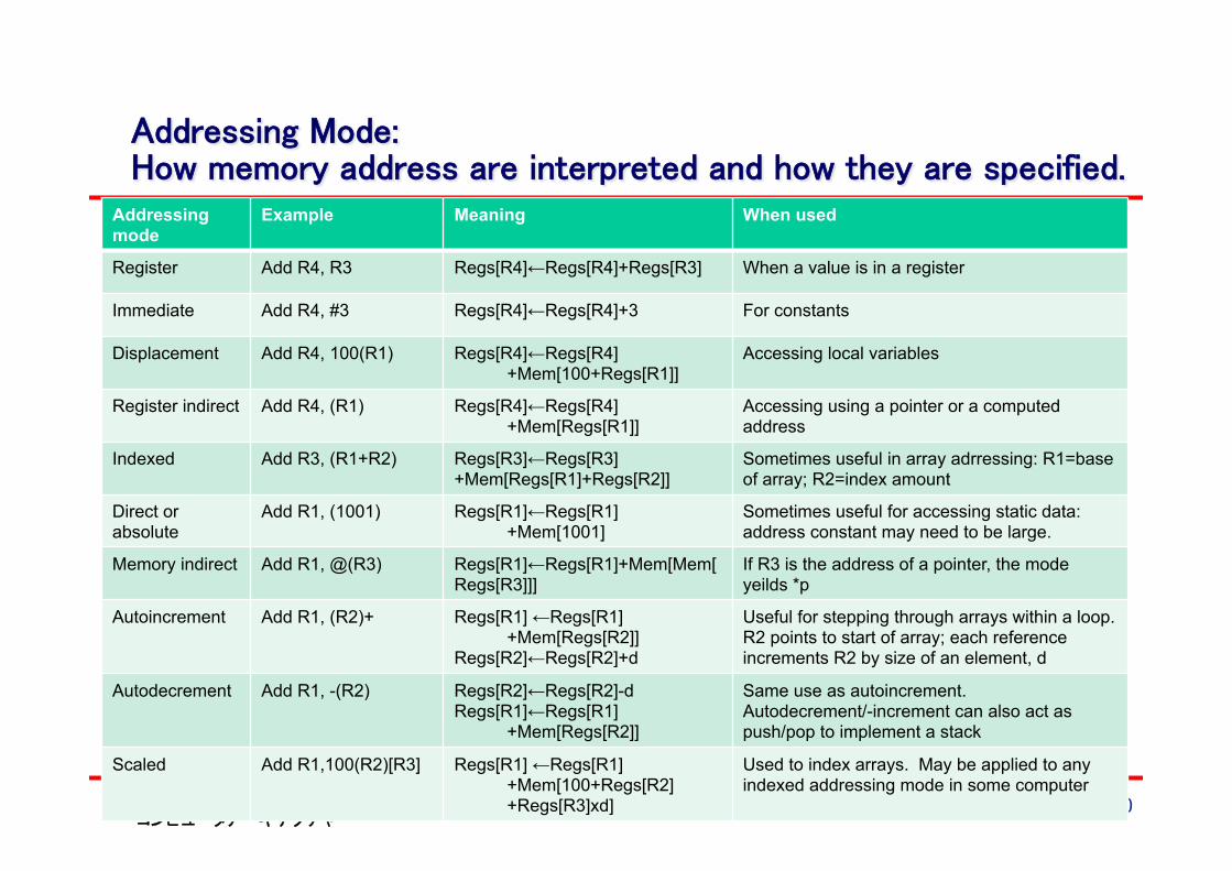
Addressing Mode: How memory address are interpreted and how they are specified.
Addressing mode
Example Meaning When used
Register Add R4, R3 Regs[R4]←Regs[R4]+Regs[R3] When a value is in a register
Immediate Add R4, #3 Regs[R4]←Regs[R4]+3 For constants
Displacement Add R4, 100(R1) Regs[R4]←Regs[R4] +Mem[100+Regs[R1]]
Accessing local variables
Register indirect Add R4, (R1) Regs[R4]←Regs[R4] +Mem[Regs[R1]]
Accessing using a pointer or a computed address
Indexed Add R3, (R1+R2) Regs[R3]←Regs[R3] +Mem[Regs[R1]+Regs[R2]]
Sometimes useful in array adrressing: R1=base of array; R2=index amount
Direct or absolute
Add R1, (1001) Regs[R1]←Regs[R1] +Mem[1001]
Sometimes useful for accessing static data: address constant may need to be large.
Memory indirect Add R1, @(R3) Regs[R1]←Regs[R1]+Mem[Mem[Regs[R3]]]
If R3 is the address of a pointer, the mode yeilds *p
Autoincrement Add R1, (R2)+ Regs[R1] ←Regs[R1] +Mem[Regs[R2]]
Regs[R2]←Regs[R2]+d
Useful for stepping through arrays within a loop. R2 points to start of array; each reference increments R2 by size of an element, d
Autodecrement Add R1, -(R2) Regs[R2]←Regs[R2]-d Regs[R1]←Regs[R1]
+Mem[Regs[R2]]
Same use as autoincrement. Autodecrement/-increment can also act as push/pop to implement a stack
Scaled Add R1,100(R2)[R3] Regs[R1] ←Regs[R1] +Mem[100+Regs[R2] +Regs[R3]xd]
Used to index arrays. May be applied to any indexed addressing mode in some computer
2012年 東芝S&Sインスティチュート コンピュータアーキテクチャ
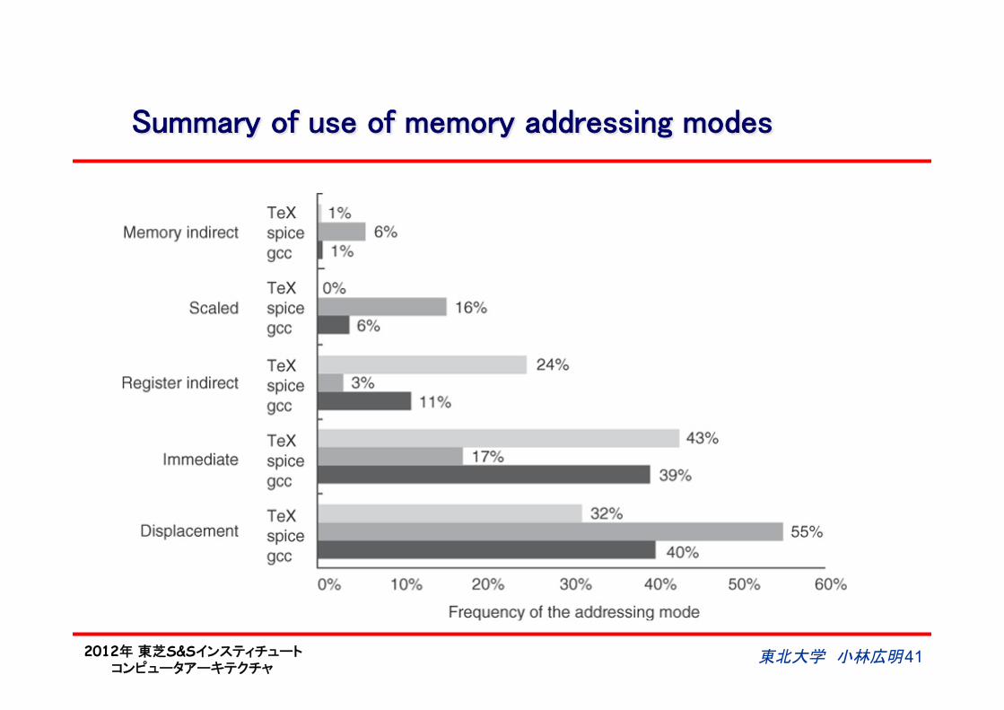
Summary of use of memory addressing modes
東北大学 小林広明 41
2012年 東芝S&Sインスティチュート コンピュータアーキテクチャ
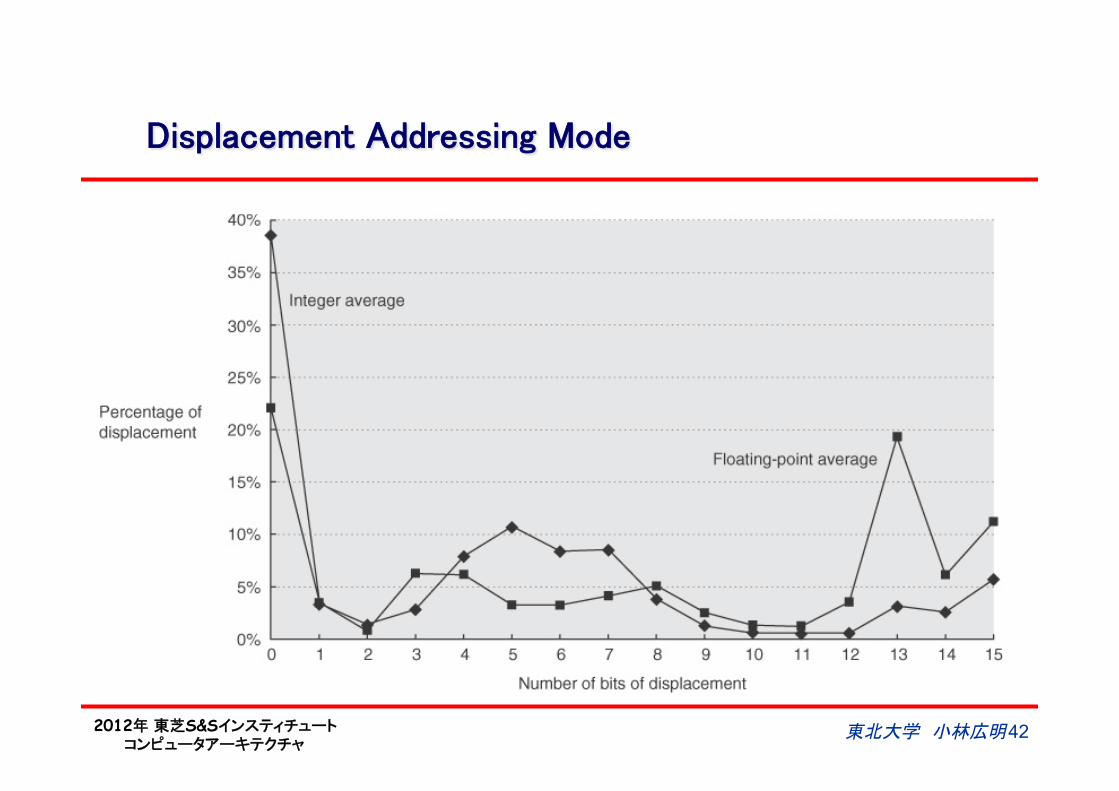
Displacement Addressing Mode
東北大学 小林広明 42
2012年 東芝S&Sインスティチュート コンピュータアーキテクチャ
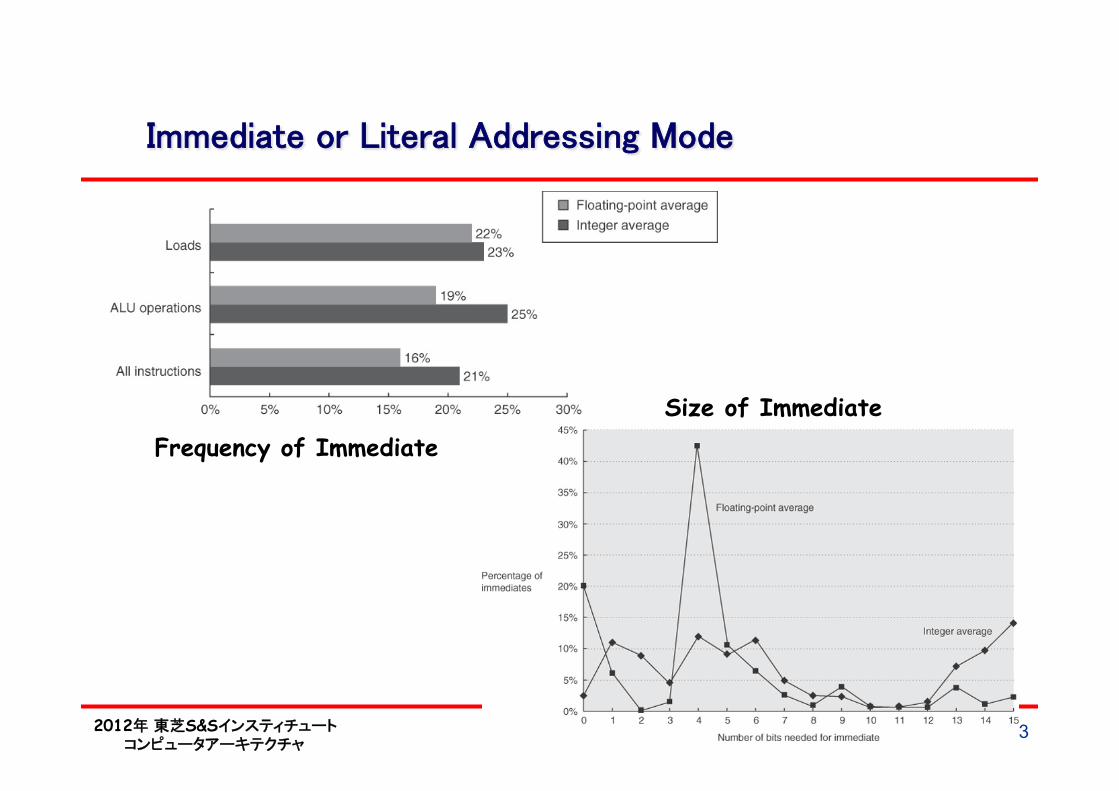
Immediate or Literal Addressing Mode
東北大学 小林広明 43
Frequency of Immediate
Size of Immediate
2012年 東芝S&Sインスティチュート コンピュータアーキテクチャ
東北大学 小林広明 44
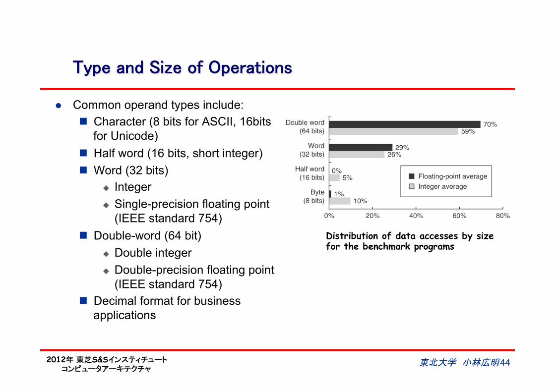
Type and Size of Operations
l Common operand types include: n Character (8 bits for ASCII, 16bits
for Unicode) n Half word (16 bits, short integer) n Word (32 bits)
u Integer u Single-precision floating point
(IEEE standard 754) n Double-word (64 bit)
u Double integer u Double-precision floating point
(IEEE standard 754) n Decimal format for business
applications
Distribution of data accesses by size for the benchmark programs
2012年 東芝S&Sインスティチュート コンピュータアーキテクチャ
Floating-Point Numbers
l Fixed-point notation n Binary point is fixed, e.g.,
rightmost for integers J Easy for arithmetic operations L Representable range limited
n-bit (fixed)
m-bit (fixed)
Integer part sign Binary point
(fixed)
Fraction part
• Floating-point notation – Numbers are presented by a
mantissa (significand) and an exponent, similar to scientific notation
J Representable range extended L Complicated processing needed
for arithmetic operations
p-bit (fixed)
q-bit (fixed)
Mantissa (Significand) exponent
東北大学 小林広明 45
2012年 東芝S&Sインスティチュート コンピュータアーキテクチャ
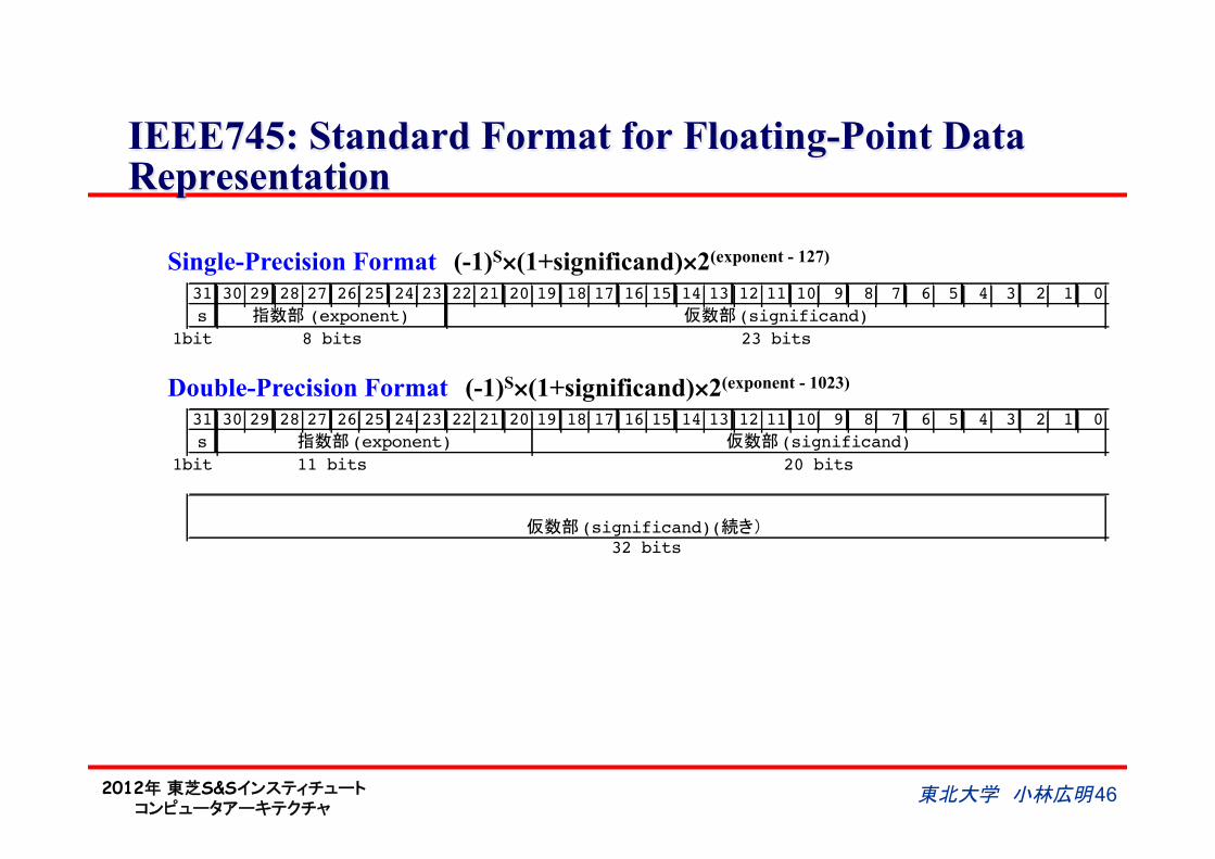
IEEE745: Standard Format for Floating-Point Data Representation
31 30 29 28 27 26 25 24 23 22 21 20 19 18 17 16 15 14 13 12 11 10 9 8 7 6 5 4 3 2 1 0
s ��� (exponent) ���(significand)
8 bits 23 bits
31 30 29 28 27 26 25 24 23 22 21 20 19 18 17 16 15 14 13 12 11 10 9 8 7 6 5 4 3 2 1 0
s ���(exponent) ���(significand)
11 bits 20 bits
���(significand)(���32 bits
1bit
1bit
Single-Precision Format (-1)S×(1+significand)×2(exponent - 127)
Double-Precision Format (-1)S×(1+significand)×2(exponent - 1023)
東北大学 小林広明 46
2012年 東芝S&Sインスティチュート コンピュータアーキテクチャ
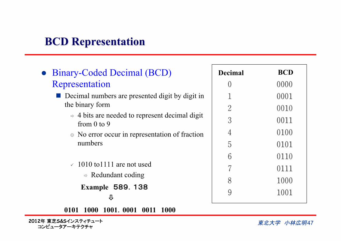
BCD Representation
l Binary-Coded Decimal (BCD) Representation n Decimal numbers are presented digit by digit in
the binary form ð 4 bits are needed to represent decimal digit
from 0 to 9 J No error occur in representation of fraction
numbers
ü 1010 to1111 are not used ð Redundant coding
Example 589.138
ò
0101 1000 1001.0001 0011 1000
Decimal BCD
東北大学 小林広明 47

2012年 東芝S&Sインスティチュート コンピュータアーキテクチャ
Additions on BCD Numbers
l Add 4-bit (BCD digit) by 4-bit from the lower l As there is unused range from 1010 to 1111, if a result of addition of each digit
is greater than 9, add offset 110(6) for compensation and carry generation
Add offset 110
Add offset 110
>1010
carry
東北大学 小林広明 48
2012年 東芝S&Sインスティチュート コンピュータアーキテクチャ
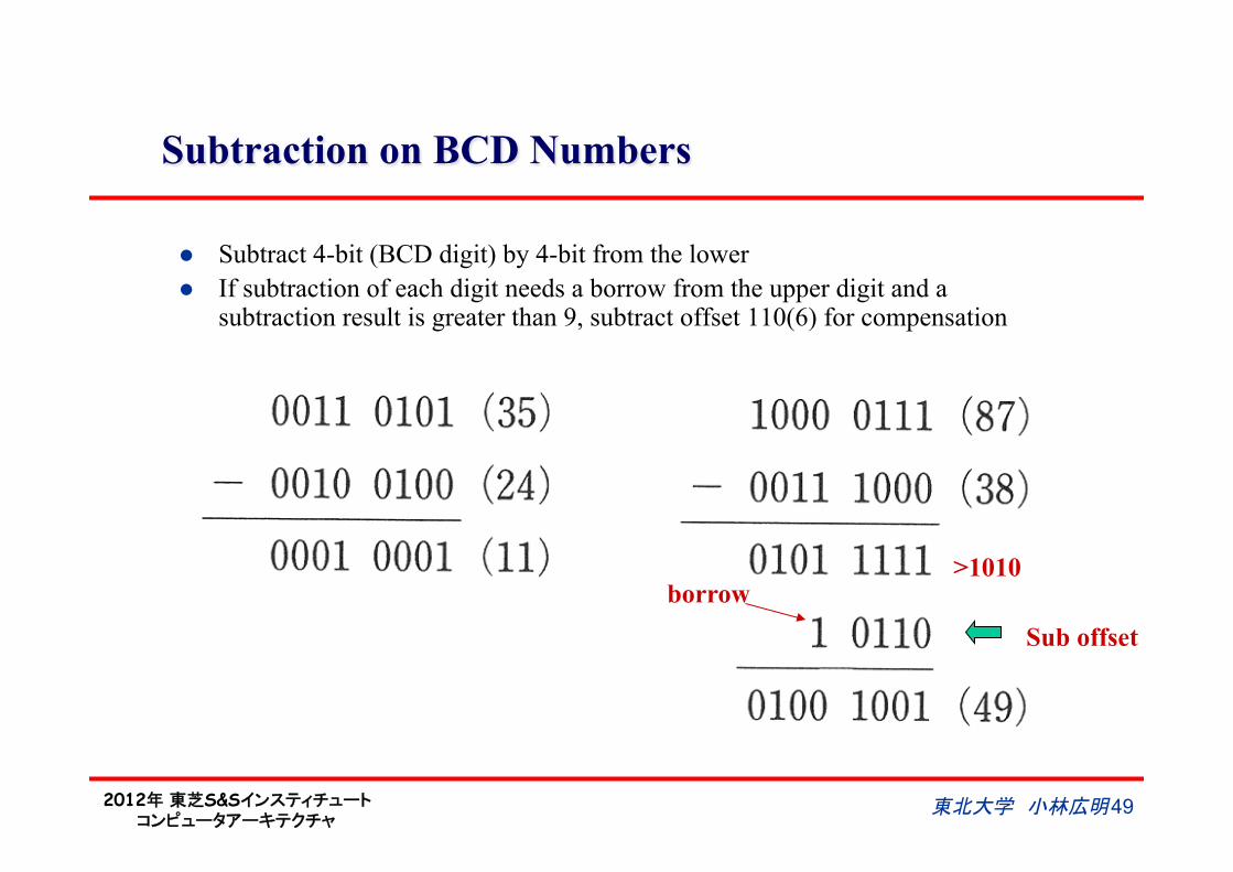
Subtraction on BCD Numbers
l Subtract 4-bit (BCD digit) by 4-bit from the lower l If subtraction of each digit needs a borrow from the upper digit and a
subtraction result is greater than 9, subtract offset 110(6) for compensation
Sub offset
>1010 borrow
東北大学 小林広明 49
2012年 東芝S&Sインスティチュート コンピュータアーキテクチャ
東北大学 小林広明 50
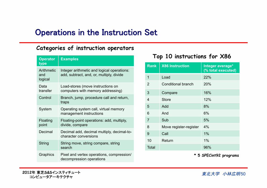
Operations in the Instruction Set
Operator type
Examples
Arithmetic and logical
Integer arithmetic and logical operations: add, subtract, and, or, multiply, divide
Data transfer
Load-stores (move instructions on computers with memory addressing)
Control Branch, jump, procedure call and return, traps
System Operating system call, virtual memory management instructions
Floating point
Floating-point operations: add, multiply, divide, compare
Decimal Decimal add, decimal multiply, decimal-to-character conversions
String String move, string compare, string search
Graphics Pixel and vertex operations, compression/decompression operations
Rank X86 Instruction Integer average* (% total executed)
1 Load 22%
2 Conditional branch 20%
3 Compare 16%
4 Store 12%
5 Add 8%
6 And 6%
7 Sub 5%
8 Move register-register 4%
9 Call 1%
10 Return 1%
Total 96%
Top 10 instructions for X86
Categories of instruction operators
* 5 SPECint92 programs
2012年 東芝S&Sインスティチュート コンピュータアーキテクチャ
東北大学 小林広明 51
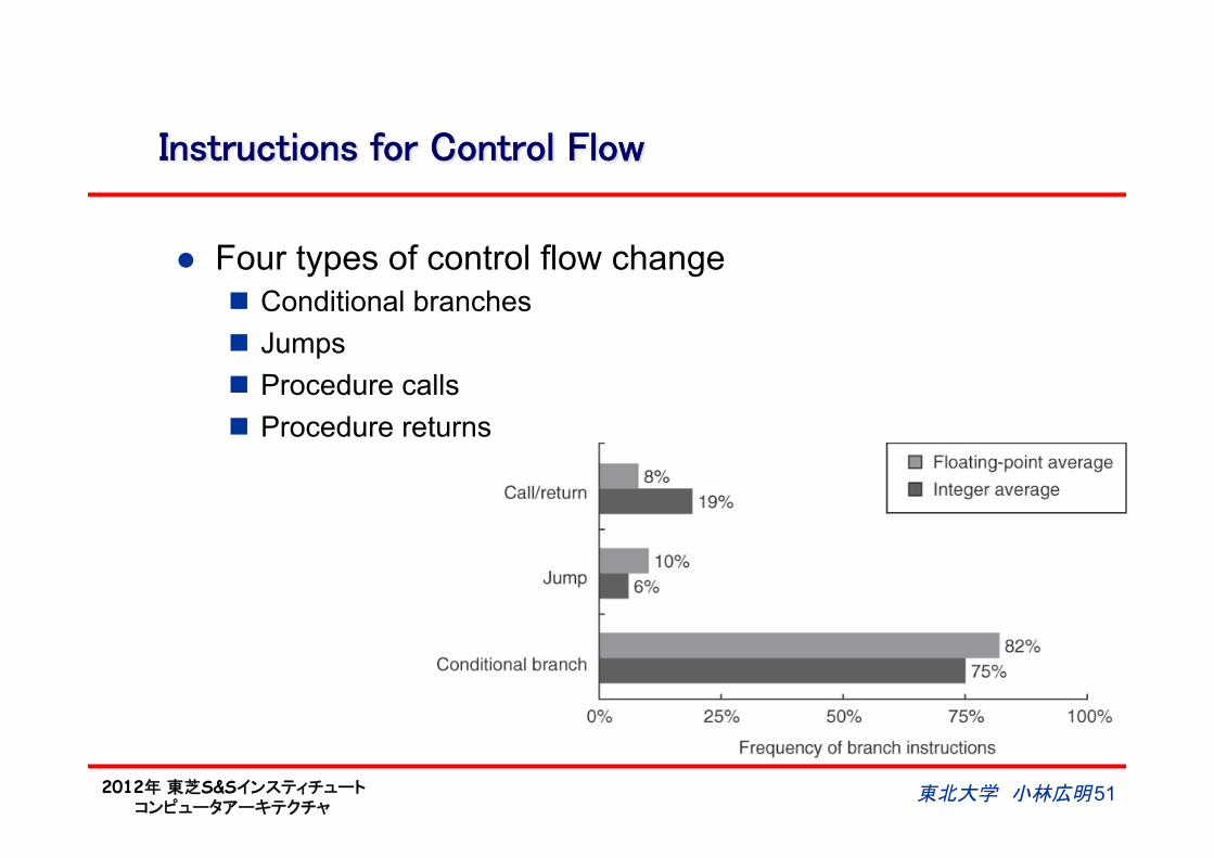
Instructions for Control Flow
l Four types of control flow change n Conditional branches n Jumps n Procedure calls n Procedure returns
2012年 東芝S&Sインスティチュート コンピュータアーキテクチャ
Addressing Modes for Control Flow Instructions
l The most common way to specify the destination is to supply a displacement that is added to the program counter (PC) n PC-relative
l Advantages: n The target is often near the current instruction n Specifying the position relative to the current PC requires
fewer bits. n Allow the code to run independently of where it is loaded
u Position independence u Eliminate some work when the program is linked and is also
useful in programs linked dynamically during execution
東北大学 小林広明 52
2012年 東芝S&Sインスティチュート コンピュータアーキテクチャ
Register Indirect Jump
l Registers are used to implement returns and indirect jumps when the target is not known at compile time n Case or switch statements n Virtual functions or methods in object-oriented languages
like C++ or Java u which allow different routines to be called depending on the
type of the argument n Higher-order functions or function pointers in languages like
C or C++ u which allow functions to be passed as arguments
n Dynamic shared libraries u Which allow a library to be loaded and linked at runtime only
when it is actually invoked by the program rather than loaded and linked statically before the program is run.
東北大学 小林広明 53
2012年 東芝S&Sインスティチュート コンピュータアーキテクチャ
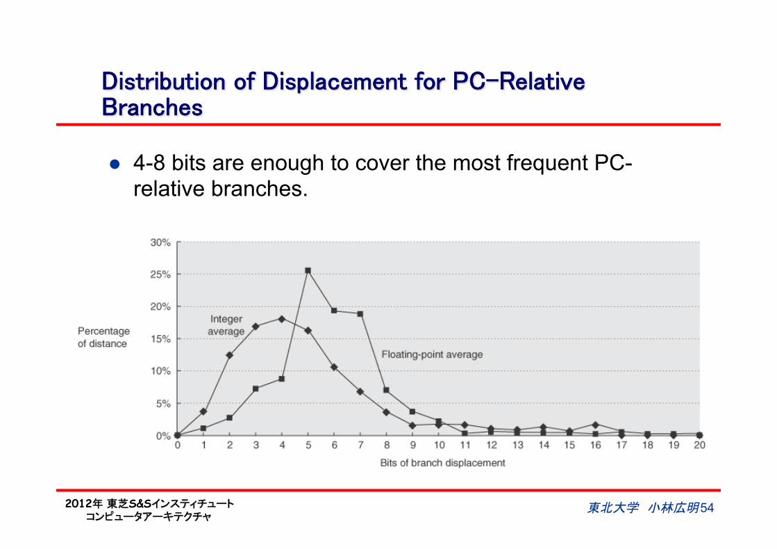
Distribution of Displacement for PC-Relative Branches
l 4-8 bits are enough to cover the most frequent PC-relative branches.
東北大学 小林広明 54
2012年 東芝S&Sインスティチュート コンピュータアーキテクチャ
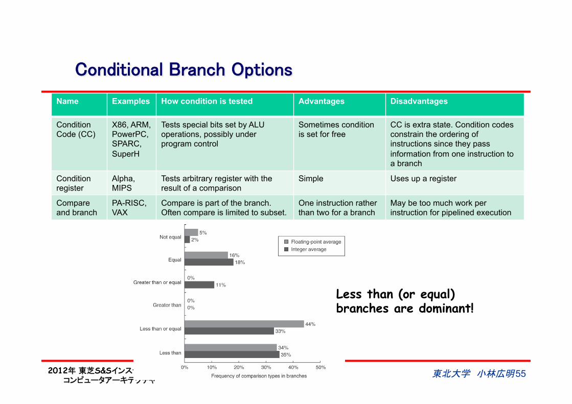
Conditional Branch Options
Name Examples How condition is tested Advantages Disadvantages
Condition Code (CC)
X86, ARM, PowerPC, SPARC, SuperH
Tests special bits set by ALU operations, possibly under program control
Sometimes condition is set for free
CC is extra state. Condition codes constrain the ordering of instructions since they pass information from one instruction to a branch
Condition register
Alpha, MIPS
Tests arbitrary register with the result of a comparison
Simple Uses up a register
Compare and branch
PA-RISC, VAX
Compare is part of the branch. Often compare is limited to subset.
One instruction rather than two for a branch
May be too much work per instruction for pipelined execution
東北大学 小林広明 55
Less than (or equal) branches are dominant!
2012年 東芝S&Sインスティチュート コンピュータアーキテクチャ
東北大学 小林広明 56
Encoding an Instruction Set
l The architect must balance several competing forces n The desire to have as many registers and addressing modes
as possible n The impact of the size of the register and addressing mode
fields on the average instruction size and hence on the average program size
n A desire to have instructions encoded into lengths that will be easy to handle in a pipelined implementation
u Multiples of bytes, rather than a arbitrary bit length u Fixed-length instruction to gain implementation benefits while
sacrificing average code size.
2012年 東芝S&Sインスティチュート コンピュータアーキテクチャ
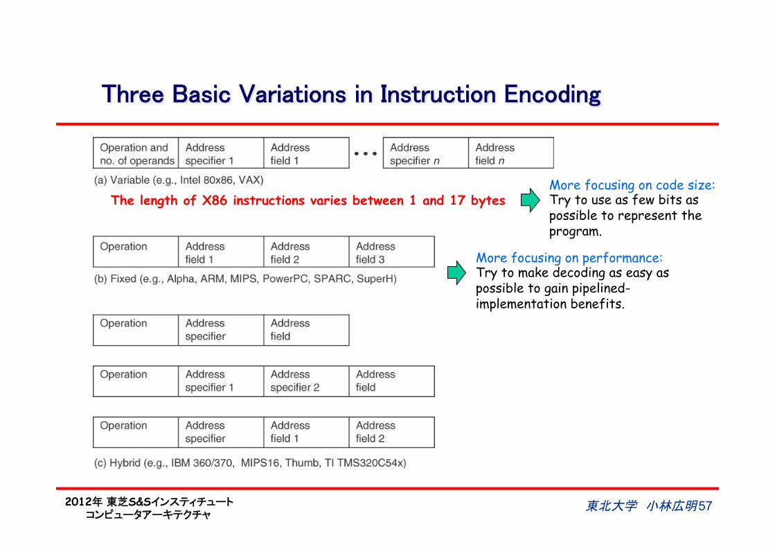
Three Basic Variations in Instruction Encoding
東北大学 小林広明 57
The length of X86 instructions varies between 1 and 17 bytes More focusing on code size: Try to use as few bits as possible to represent the program.
More focusing on performance: Try to make decoding as easy as possible to gain pipelined-implementation benefits.
2012年 東芝S&Sインスティチュート コンピュータアーキテクチャ
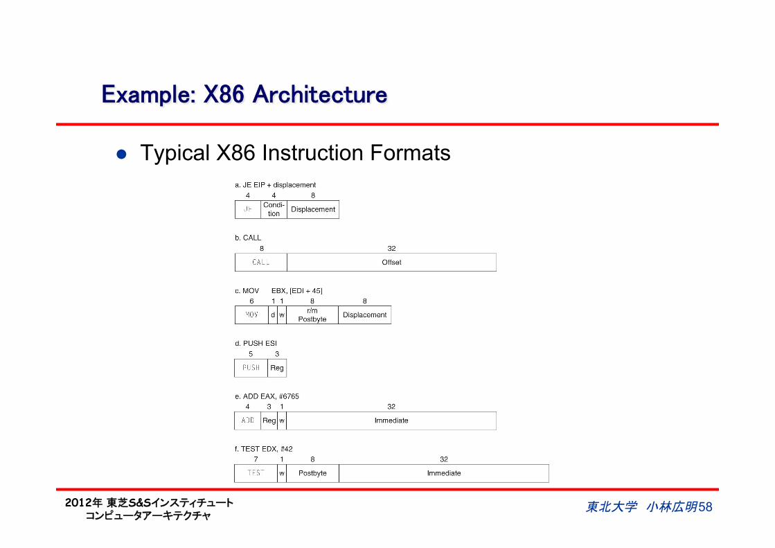
Example: X86 Architecture
l Typical X86 Instruction Formats
東北大学 小林広明 58
2012年 東芝S&Sインスティチュート コンピュータアーキテクチャ
Example of Machine Instructions on X86
東北大学 小林広明 59
2012年 東芝S&Sインスティチュート コンピュータアーキテクチャ
東北大学 小林広明 60
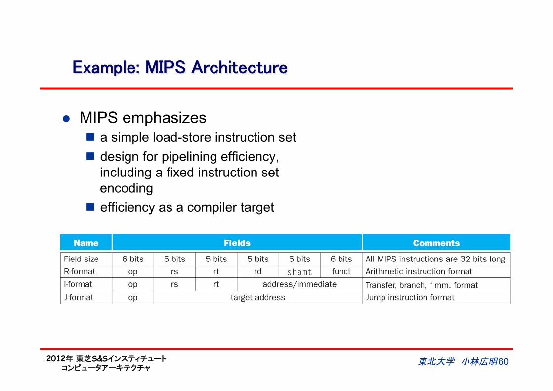
Example: MIPS Architecture
l MIPS emphasizes n a simple load-store instruction set n design for pipelining efficiency,
including a fixed instruction set encoding
n efficiency as a compiler target
2012年 東芝S&Sインスティチュート コンピュータアーキテクチャ
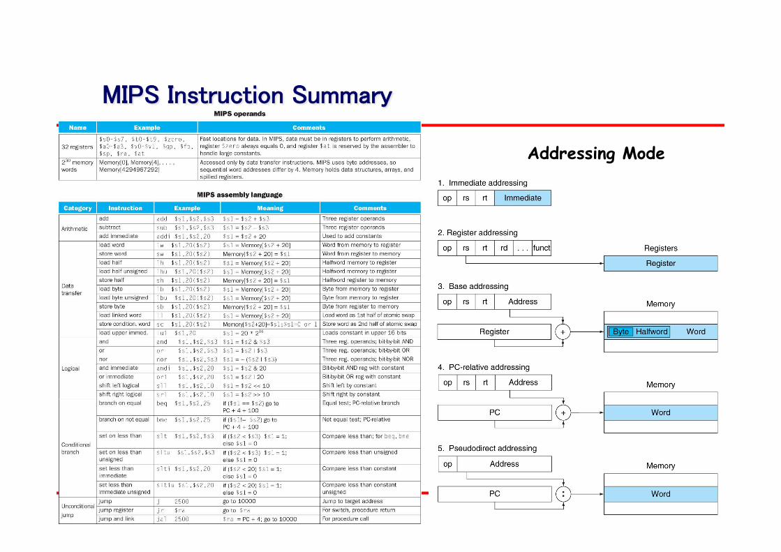
MIPS Instruction Summary
東北大学 小林広明 61
Addressing Mode
2012年 東芝S&Sインスティチュート コンピュータアーキテクチャ
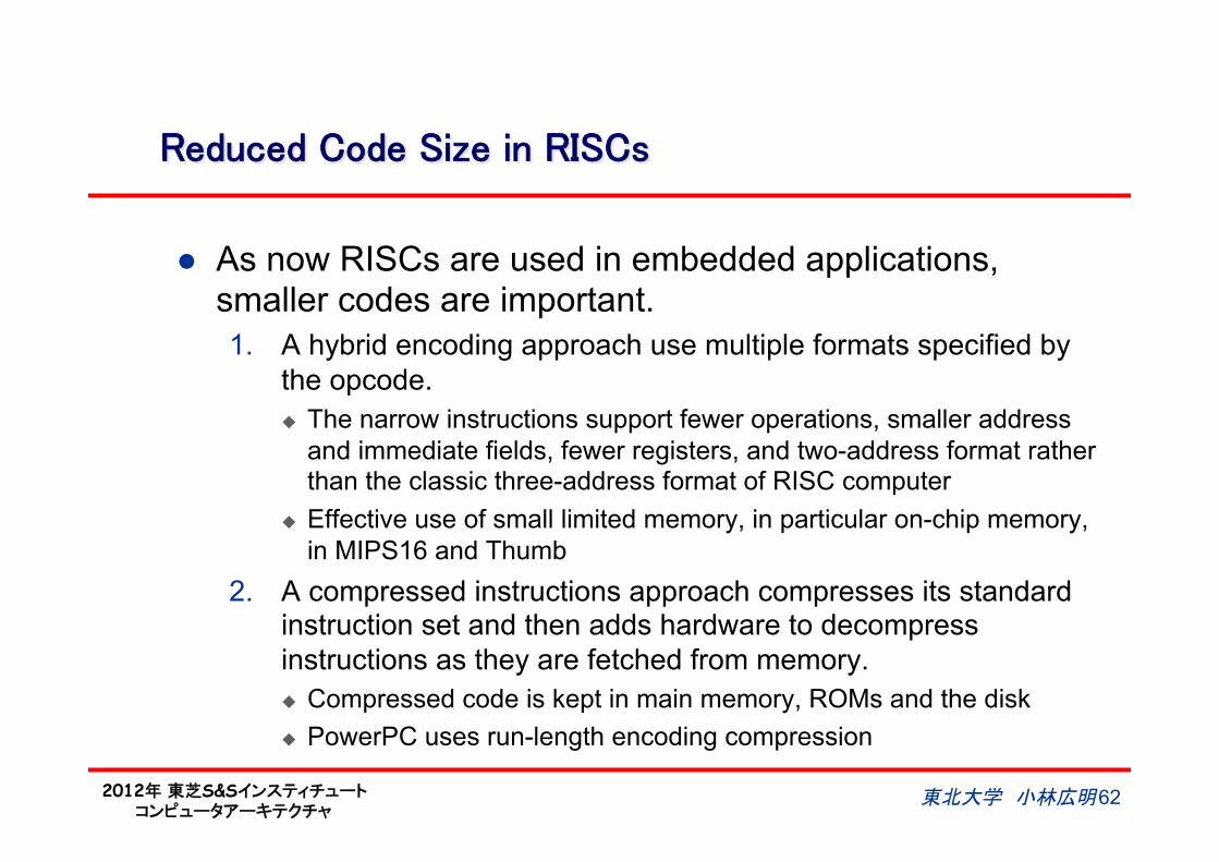
Reduced Code Size in RISCs
l As now RISCs are used in embedded applications, smaller codes are important. 1. A hybrid encoding approach use multiple formats specified by
the opcode. u The narrow instructions support fewer operations, smaller address
and immediate fields, fewer registers, and two-address format rather than the classic three-address format of RISC computer
u Effective use of small limited memory, in particular on-chip memory, in MIPS16 and Thumb
2. A compressed instructions approach compresses its standard instruction set and then adds hardware to decompress instructions as they are fetched from memory. u Compressed code is kept in main memory, ROMs and the disk u PowerPC uses run-length encoding compression
東北大学 小林広明 62
2012年 東芝S&Sインスティチュート コンピュータアーキテクチャ
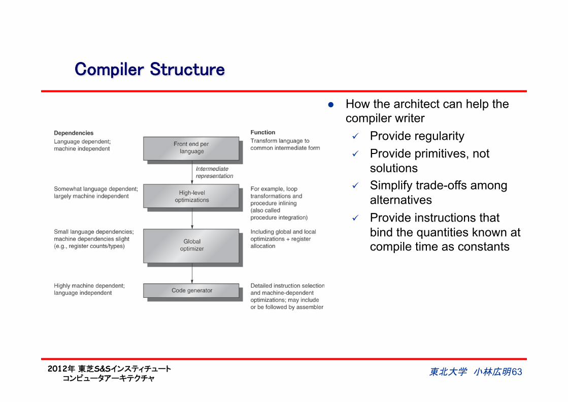
Compiler Structure
東北大学 小林広明 63
l How the architect can help the compiler writer ü Provide regularity ü Provide primitives, not
solutions ü Simplify trade-offs among
alternatives ü Provide instructions that
bind the quantities known at compile time as constants
2012年 東芝S&Sインスティチュート コンピュータアーキテクチャ
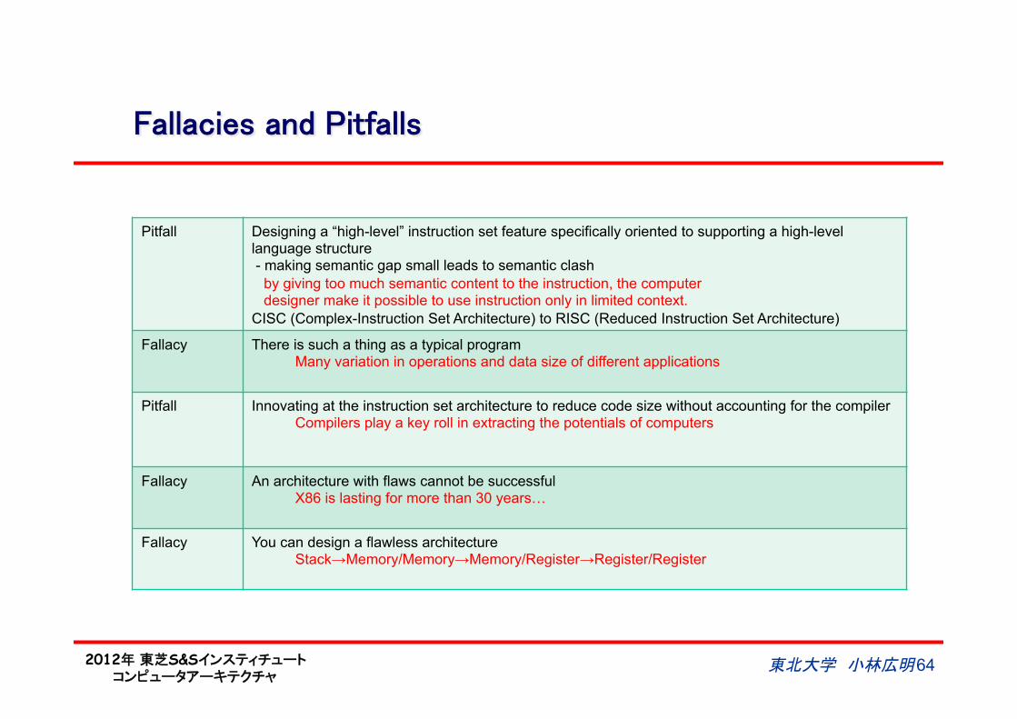
Fallacies and Pitfalls
東北大学 小林広明 64
Pitfall Designing a “high-level” instruction set feature specifically oriented to supporting a high-level language structure - making semantic gap small leads to semantic clash by giving too much semantic content to the instruction, the computer designer make it possible to use instruction only in limited context. CISC (Complex-Instruction Set Architecture) to RISC (Reduced Instruction Set Architecture)
Fallacy There is such a thing as a typical program Many variation in operations and data size of different applications
Pitfall Innovating at the instruction set architecture to reduce code size without accounting for the compiler Compilers play a key roll in extracting the potentials of computers
Fallacy An architecture with flaws cannot be successful X86 is lasting for more than 30 years…
Fallacy You can design a flawless architecture Stack→Memory/Memory→Memory/Register→Register/Register
2012年 東芝S&Sインスティチュート コンピュータアーキテクチャ
東北大学 小林広明 65
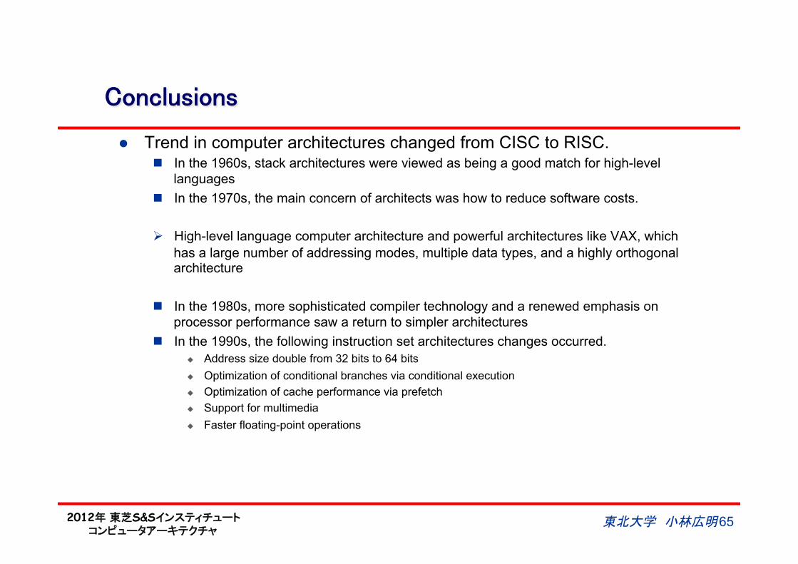
Conclusions
l Trend in computer architectures changed from CISC to RISC. n In the 1960s, stack architectures were viewed as being a good match for high-level
languages n In the 1970s, the main concern of architects was how to reduce software costs.
Ø High-level language computer architecture and powerful architectures like VAX, which has a large number of addressing modes, multiple data types, and a highly orthogonal architecture
n In the 1980s, more sophisticated compiler technology and a renewed emphasis on processor performance saw a return to simpler architectures
n In the 1990s, the following instruction set architectures changes occurred. u Address size double from 32 bits to 64 bits u Optimization of conditional branches via conditional execution u Optimization of cache performance via prefetch u Support for multimedia u Faster floating-point operations


![Sistem Berkas[sequential]](https://img.pdfslide.tips/doc/110x75/5571f97949795991698fa6ee/sistem-berkassequential.jpg)