Embed Size (px)
Citation preview
Chapter 3 Loaders andLinkers

Outline 3.1 Basic Loader Functions 3.2 Machine-Dependent Loader Features 3.3 Machine-Independent Loader Features 3.4 Loader Design Options 3.5 Implementation Examples
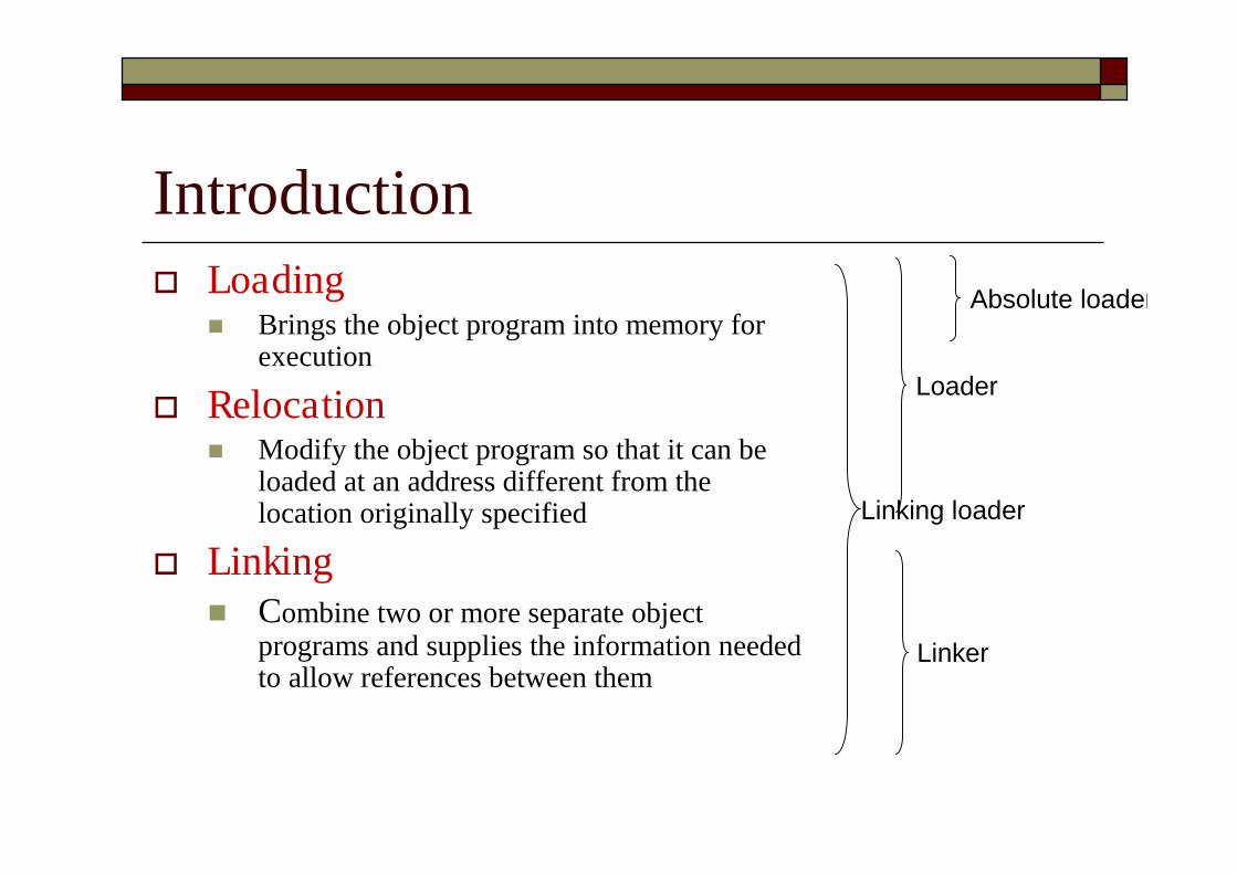
Introduction Loading
Brings the object program into memory forexecution
Relocation Modify the object program so that it can be
loaded at an address different from thelocation originally specified
Linking Combine two or more separate object
programs and supplies the information neededto allow references between them
Absolute loader
Loader
Linking loader
Linker
Overview of Chapter 3 Type of loaders
Assemble-and-go loader Absolute loader (bootstrap loader) Relocating loader (relative loader) Direct linking loader
Design options Linkage editors Dynamic linking Bootstrap loaders

3.1 Basic Loader Functions The most fundamental functions of a loader: Bringing an object program into memory and
starting its execution Design of an Assemble-and-Go Loader
Design of an Absolute Loader
A Simple Bootstrap Loader
3.1.0 Assemble-and-Go Loader Characteristic
The object code is produced directly in memory forimmediate execution after assembly
Advantage Useful for program development and testing
Disadvantage Whenever the assembly program is to be executed, it has
to be assembled again Programs consist of many control sections have to be
coded in the same language
3.1.1 Design of an Absolute Loader Absolute Program (e.g. SIC programs)
Advantage Simple and efficient
Disadvantages The need for programmer to specify the actual address at which it
will be loaded into memory Difficult to use subroutine libraries efficiently
Absolute loader only performs loading function Does not need to perform linking and program relocation. All functions are accomplished in a single pass.
Design of an Absolute Loader (Cont.) In a single pass Check the Header record for program name,
starting address, and length Bring the object program contained in the Text
record to the indicated address No need to perform program linking and
relocation Start the execution by jumping to the address
specified in the End record
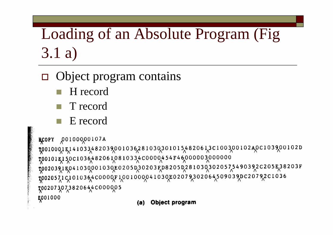
Loading of an Absolute Program (Fig3.1 a) Object program contains H record T record E record
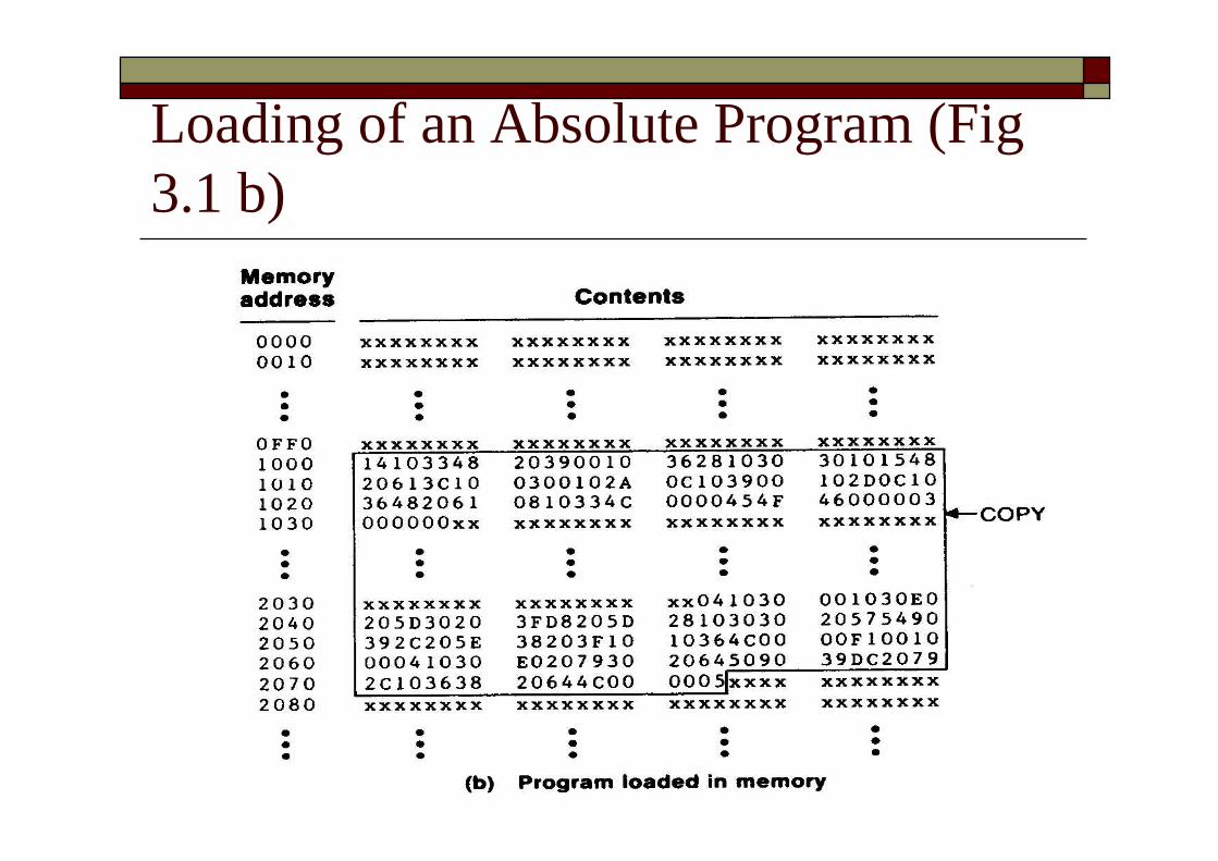
Loading of an Absolute Program (Fig3.1 b)
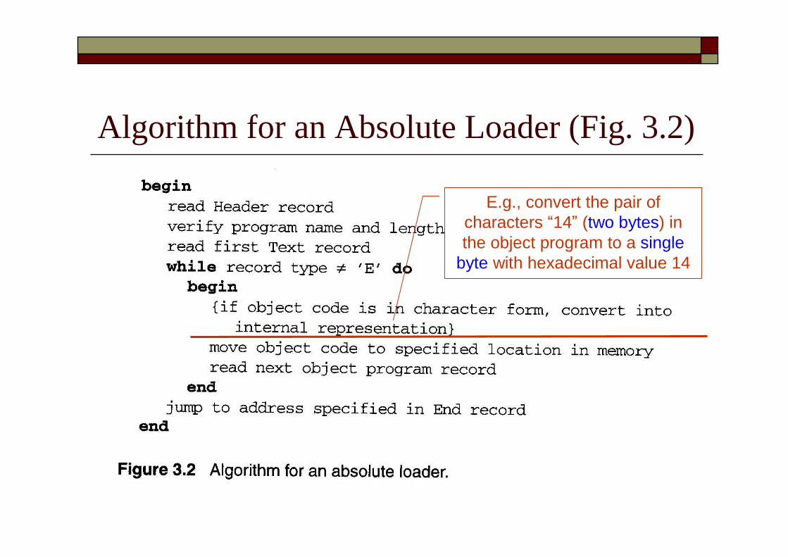
Algorithm for an Absolute Loader (Fig. 3.2)
E.g., convert the pair ofcharacters “14”(two bytes) inthe object program to a single
byte with hexadecimal value 14
Object Code Representation Figure 3.1 (a)
Each byte of assembled code is given using itshexadecimal representation in character form For example, 14 (opcode of STL) occupies two bytes of memory Easy to read by human beings
Each pair of bytes from the object program record must bepacked together into one byte during loading. Inefficient in terms of both space and execution time
Thus, most machine store object programs in abinary form
3.1.2 A Simple Bootstrap Loader Bootstrap Loader When a computer is first turned on or restarted, a
special type of absolute loader, called a bootstraploader is executed In PC, BIOS acts as a bootstrap loader
This bootstrap loads the first program to be runby the computer -- usually an operating system
A Simple Bootstrap Loader (Cont.) Example: a simple SIC/XE bootstrap loader (Fig. 3.3)
The bootstrap itself begins at address 0 in the memory ofthe machine
It loads the OS (or some other program) starting address0x80 The object code from device F1 is always loaded into
consecutive bytes of memory, starting at address 80.
After all the object code from device F1 has been loaded,the bootstraps jumps to address 80 Begin the execution of the program that was loaded.
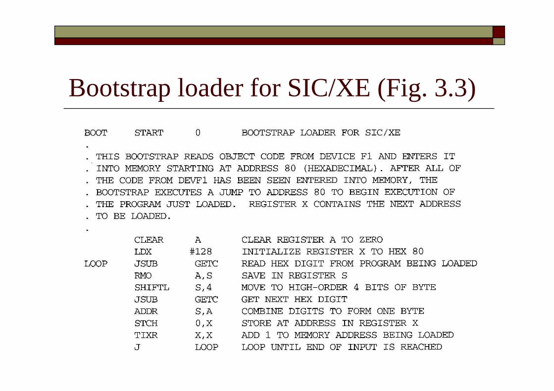
Bootstrap loader for SIC/XE (Fig. 3.3)

Bootstrap loader for SIC/XE (Fig. 3.3)
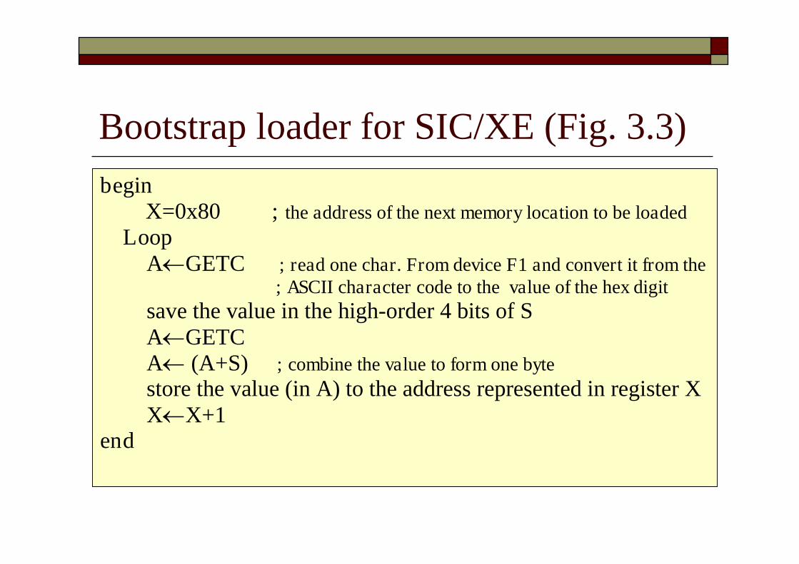
Bootstrap loader for SIC/XE (Fig. 3.3)begin
X=0x80 ; the address of the next memory location to be loadedLoop
AGETC ; read one char. From device F1 and convert it from the; ASCII character code to the value of the hex digit
save the value in the high-order 4 bits of SAGETCA (A+S) ; combine the value to form one bytestore the value (in A) to the address represented in register XXX+1
end

3.2 Machine-Dependent LoaderFeatures Drawback of absolute loaders Programmer needs to specify the actual address at
which it will be loaded into memory. Difficult to run several programs concurrently,
sharing memory between them. Difficult to use subroutine libraries.
Solution: a more complex loader that provides Program relocation Program linking

Machine-Dependent Loader Features(Cont.) 3.2.1 Relocation
3.2.2 Program Linking
3.2.3 Algorithm and Data Structures for aLinking Loader

ReviewSection 2.2.2Program Relocation
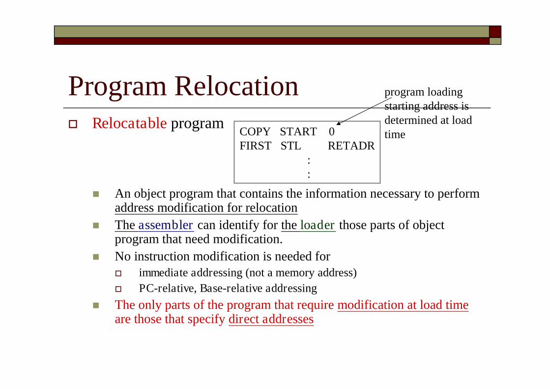
Program Relocation Relocatable program
An object program that contains the information necessary to performaddress modification for relocation
The assembler can identify for the loader those parts of objectprogram that need modification.
No instruction modification is needed for immediate addressing (not a memory address) PC-relative, Base-relative addressing
The only parts of the program that require modification at load timeare those that specify direct addresses
COPY START 0FIRST STL RETADR
::
program loadingstarting address isdetermined at loadtime
Instruction Format vs. RelocatableLoader In SIC/XE
Relative and immediate addressing Do not need to modify their object code after relocation
Extended format Whose values are affected by relocation Need to modify when relocation
In SIC Format 3 with address field
Should be modified SIC does not support PC-relative and base-relative addressing
3.2.1 Relocation Loaders that allow for program relocation are called
relocating loaders or relative loaders. Two methods for specifying relocation as part of the
object program Modification records
Suitable for a small number of relocations required When relative or immediate addressing modes are extensively used
Relocation bits Suitable for a large number of relocations required
When only direct addressing mode can be used in a machine withfixed instruction format (e.g., the standard SIC machine)
Relocation by Modification Record A Modification record is used to describe
each part of the object code that must bechanged when the program is relocated.
Fig 3.4 & 3.5 The only portions of the assembled program that
contain addresses are the extended formatinstructions on lines 15,35,65
The only items whose values are affected byrelocation.
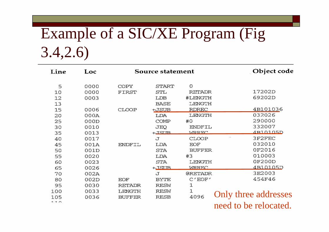
Example of a SIC/XE Program (Fig3.4,2.6)
Only three addressesneed to be relocated.
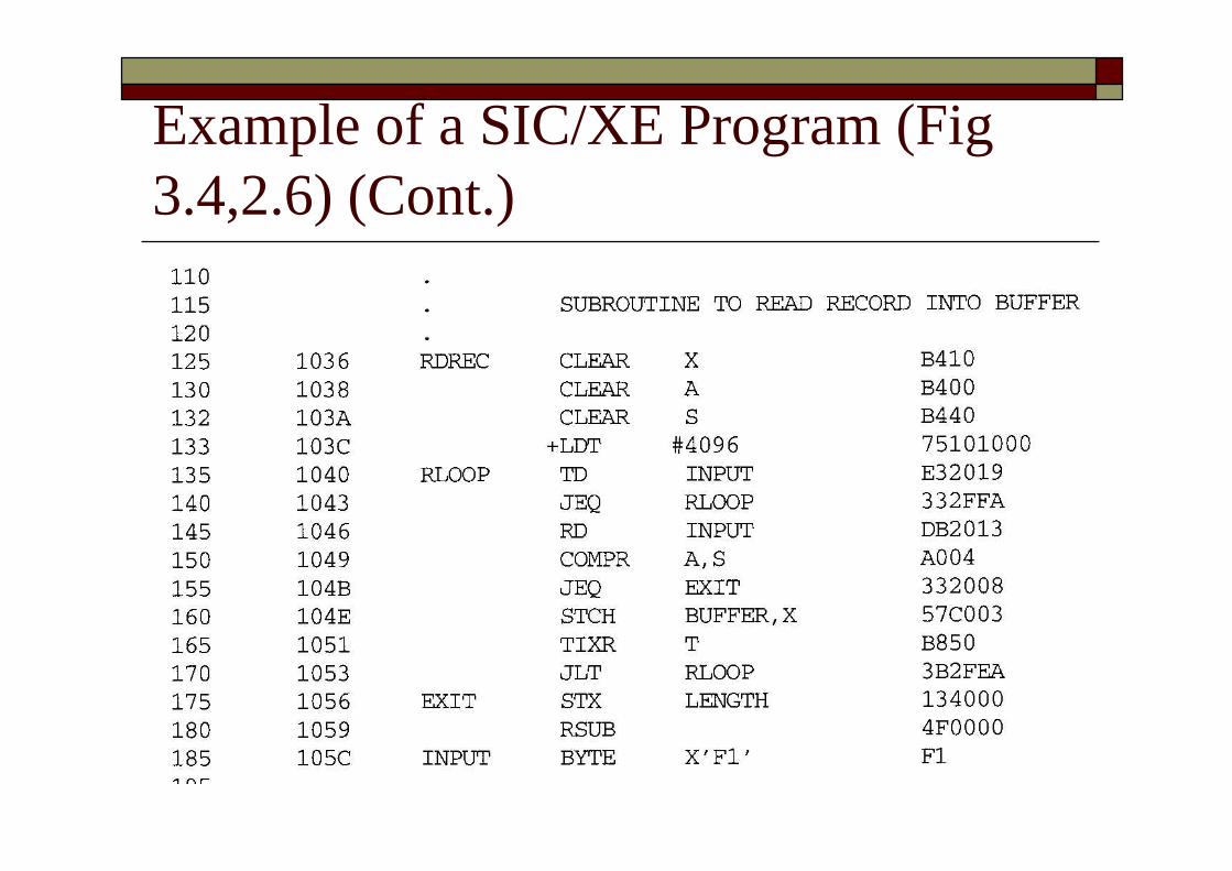
Example of a SIC/XE Program (Fig3.4,2.6) (Cont.)
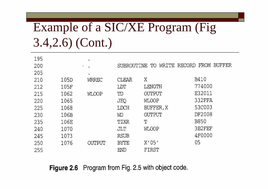
Example of a SIC/XE Program (Fig3.4,2.6) (Cont.)
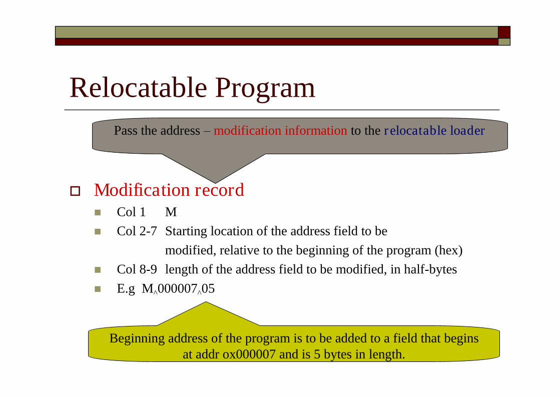
Relocatable Program
Modification record Col 1 M Col 2-7 Starting location of the address field to be
modified, relative to the beginning of the program (hex) Col 8-9 length of the address field to be modified, in half-bytes E.g M^000007^05
Pass the address –modification information to the relocatable loader
Beginning address of the program is to be added to a field that beginsat addr ox000007 and is 5 bytes in length.

Object Program with Relocation byModification Records for Fig 3.5 (Fig 2.8)
Add the starting addressof the program
There is one modification recordfor each address need to be relocated.
Relocation by Modification Record(Cont.) The Modification record scheme is a
convenient means for specifying programrelocation.
However, it is not well suited for use with allmachine architectures See Fig. 3.6.
Relocatable program for a SIC machine Most instructions use direct addressing
Too many modification records
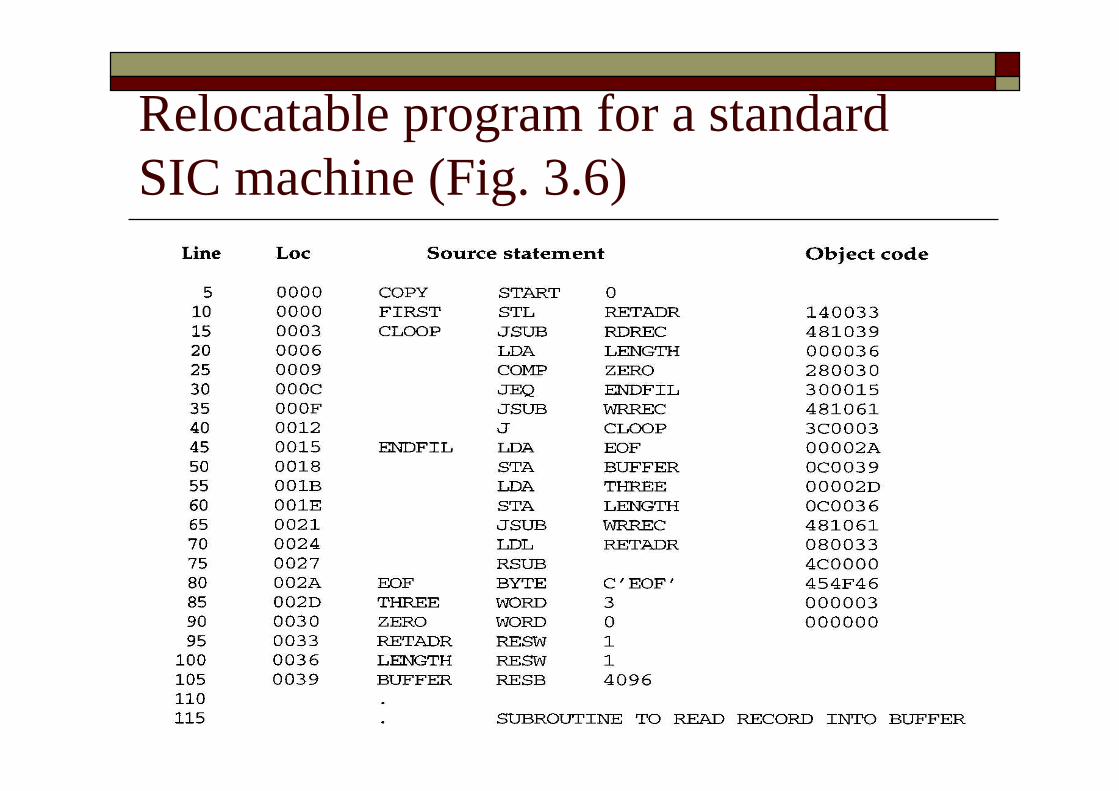
Relocatable program for a standardSIC machine (Fig. 3.6)
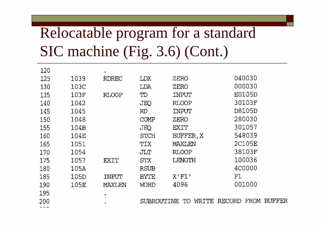
Relocatable program for a standardSIC machine (Fig. 3.6) (Cont.)
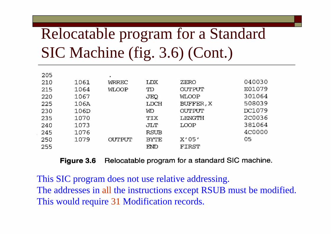
Relocatable program for a StandardSIC Machine (fig. 3.6) (Cont.)
This SIC program does not use relative addressing.The addresses in all the instructions except RSUB must be modified.This would require 31 Modification records.
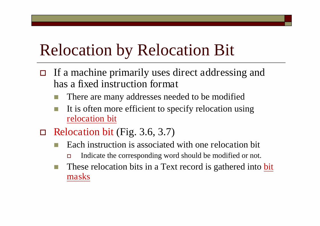
Relocation by Relocation Bit If a machine primarily uses direct addressing and
has a fixed instruction format There are many addresses needed to be modified It is often more efficient to specify relocation using
relocation bit Relocation bit (Fig. 3.6, 3.7)
Each instruction is associated with one relocation bit Indicate the corresponding word should be modified or not.
These relocation bits in a Text record is gathered into bitmasks
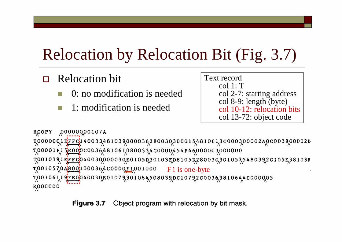
Relocation by Relocation Bit (Fig. 3.7) Relocation bit
0: no modification is needed 1: modification is needed
Text recordcol 1: Tcol 2-7: starting addresscol 8-9: length (byte)col 10-12: relocation bitscol 13-72: object code
F1 is one-byte

Relocation Bits (Cont.) Each bit mask consists of 12 relocation bit in
each Text record Since each text record contains less than 12 words Unused words are set to 0
E.g. FFC=111111111100 for line 10-55 However, only 10 words in the first text record
Relocation Bits (Cont.) Note that, any value that is to be modified
during relocation must coincide with one ofthese 3-byte segments E.g. Begin a new Text record for line 210
Because line 185 has only 1-byte object code (F1) Make the following object code does not align to 3-
byte boundary
3.2.2 Program Linking Control sections Refer to segments of codes that are translated into
independent object program units These control sections could be assembled
together or independently of one another It is necessary to provide some means for linking
control sections together External definitions External references
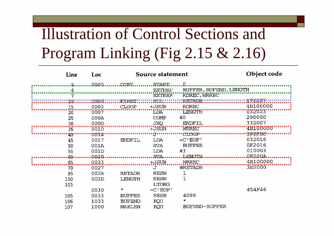
Illustration of Control Sections andProgram Linking (Fig 2.15 & 2.16)
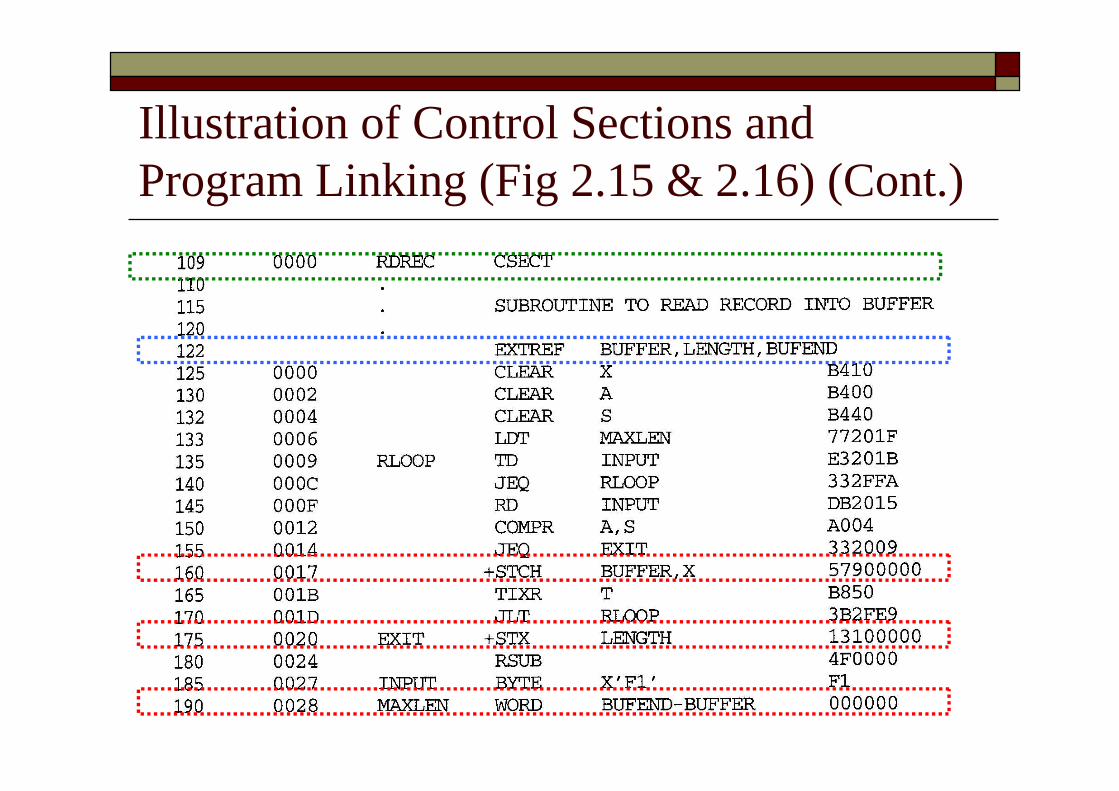
Illustration of Control Sections andProgram Linking (Fig 2.15 & 2.16) (Cont.)
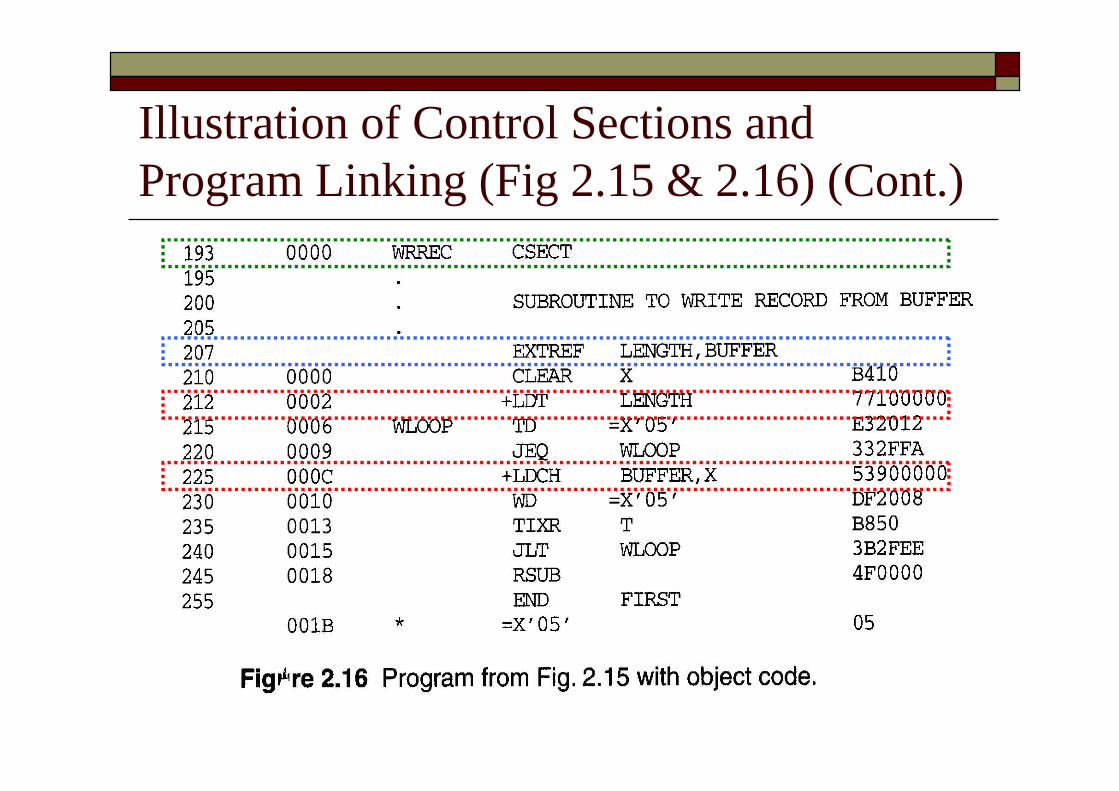
Illustration of Control Sections andProgram Linking (Fig 2.15 & 2.16) (Cont.)
Control Sections and Program Linking(Cont.) Assembler directive: secname CSECT Signals the start of a new control section E.g. 109 RDREC CSECT e.g. 193 WRREC CSECT
External references References between control sections The assembler generates information for each
external reference that will allows the loader toperform the required linking.
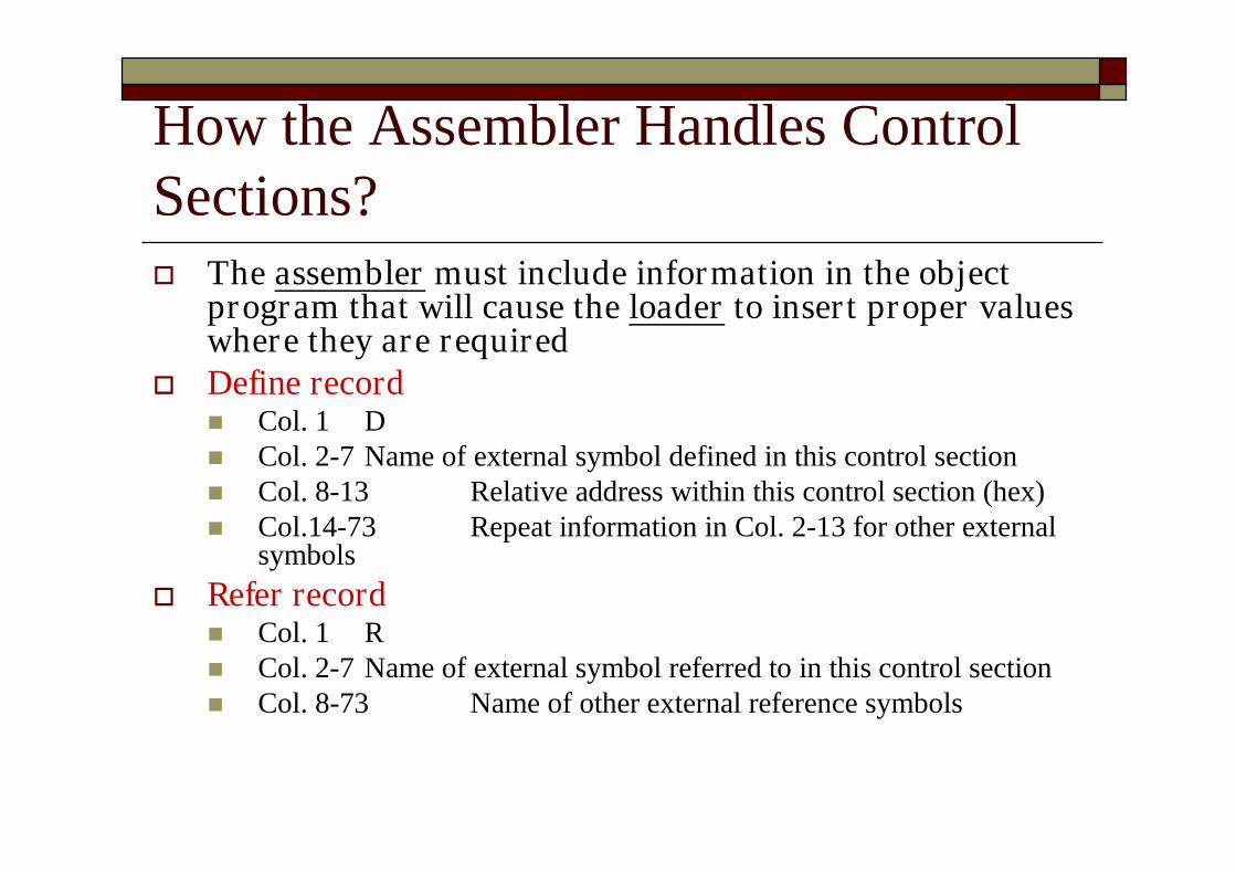
How the Assembler Handles ControlSections? The assembler must include information in the object
program that will cause the loader to insert proper valueswhere they are required
Define record Col. 1 D Col. 2-7 Name of external symbol defined in this control section Col. 8-13 Relative address within this control section (hex) Col.14-73 Repeat information in Col. 2-13 for other external
symbols Refer record
Col. 1 R Col. 2-7 Name of external symbol referred to in this control section Col. 8-73 Name of other external reference symbols
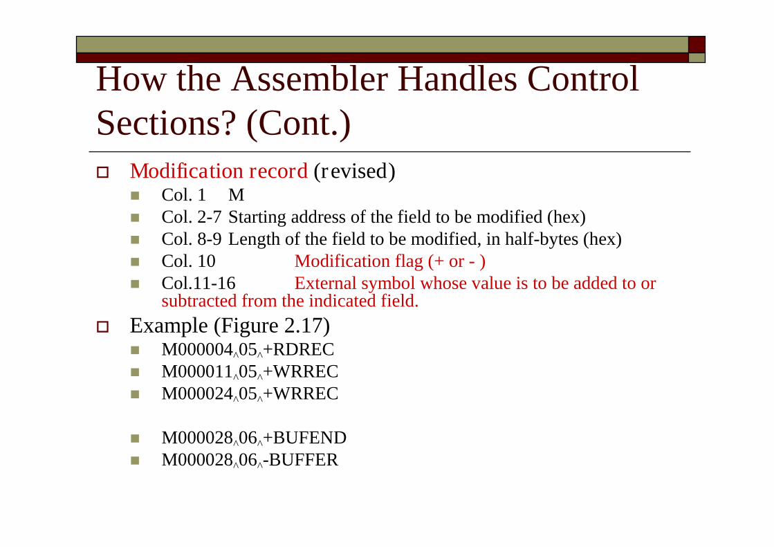
How the Assembler Handles ControlSections? (Cont.) Modification record (revised)
Col. 1 M Col. 2-7 Starting address of the field to be modified (hex) Col. 8-9 Length of the field to be modified, in half-bytes (hex) Col. 10 Modification flag (+ or - ) Col.11-16 External symbol whose value is to be added to or
subtracted from the indicated field. Example (Figure 2.17)
M000004^05^+RDREC M000011^05^+WRREC M000024^05^+WRREC
M000028^06^+BUFEND M000028^06^-BUFFER

Program Linking (Cont.) Goal of program linking Resolve the problems with EXTREF and
EXTDEF from different control sections
Example: Fig. 3.8 and Fig. 3.9
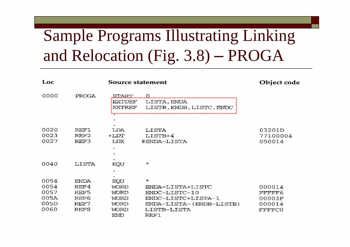
Sample Programs Illustrating Linkingand Relocation (Fig. 3.8) –PROGA

Sample Programs Illustrating Linkingand Relocation (Fig. 3.8) –PROGB
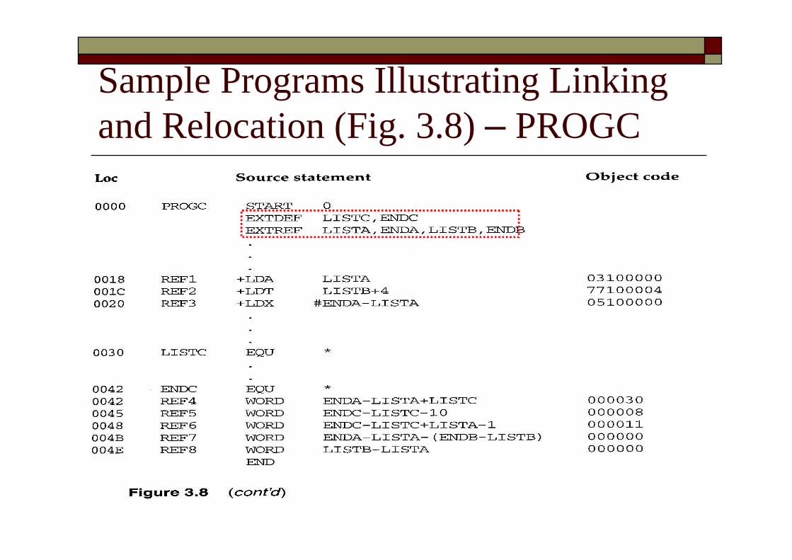
Sample Programs Illustrating Linkingand Relocation (Fig. 3.8) –PROGC

Sample Programs Illustrating Linkingand Relocation Each control section defines a list: Control section A: LISTA --- ENDA Control section B: LISTB --- ENDB Control section C: LISTC --- ENDC
Each control section contains exactly thesame set of references to these lists REF1 through REF3: instruction operands REF4 through REF8: values of data words
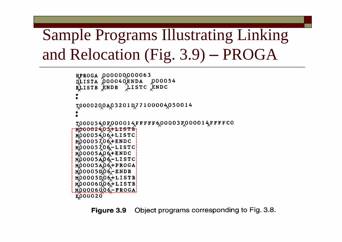
Sample Programs Illustrating Linkingand Relocation (Fig. 3.9) –PROGA

Sample Programs Illustrating Linkingand Relocation (Fig. 3.9) –PROGB

Sample Programs Illustrating Linkingand Relocation (Fig. 3.9) –PROGC

Control section A LISTA is defined within the control section. Its address is available using PC-relative addressing. No modification for relocation or linking is necessary.
Control sections B and C LISTA is an external reference. Its address is not available
An extended-format instruction with address field set to 00000is used.
A modification record is inserted into the object code Instruct the loader to add the value of LISTA to this address field.
REF1 (LISTA)
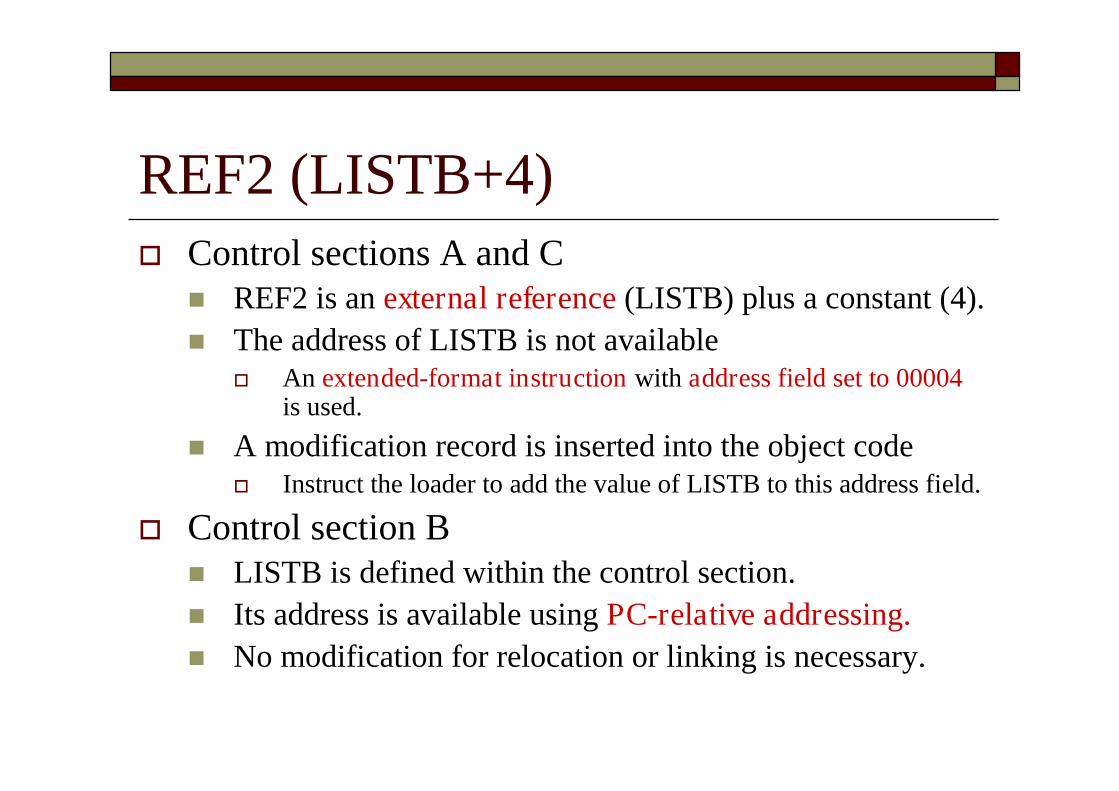
REF2 (LISTB+4) Control sections A and C
REF2 is an external reference (LISTB) plus a constant (4). The address of LISTB is not available
An extended-format instruction with address field set to 00004is used.
A modification record is inserted into the object code Instruct the loader to add the value of LISTB to this address field.
Control section B LISTB is defined within the control section. Its address is available using PC-relative addressing. No modification for relocation or linking is necessary.
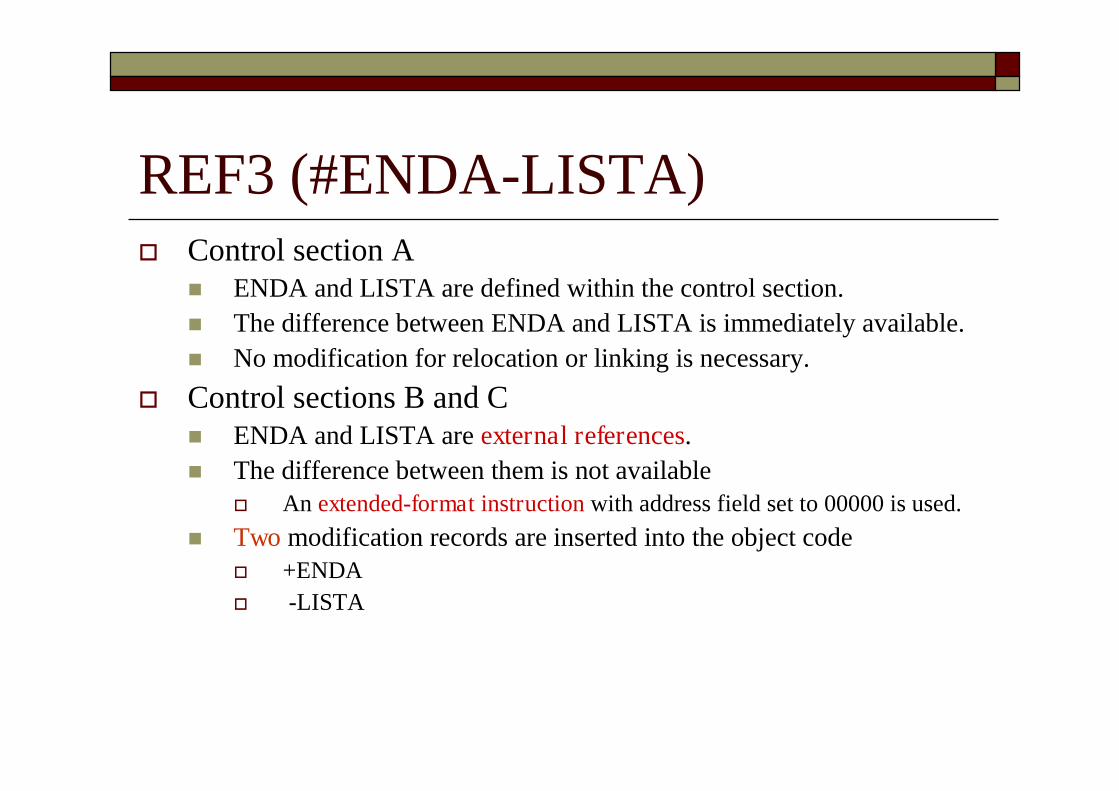
REF3 (#ENDA-LISTA) Control section A
ENDA and LISTA are defined within the control section. The difference between ENDA and LISTA is immediately available. No modification for relocation or linking is necessary.
Control sections B and C ENDA and LISTA are external references. The difference between them is not available
An extended-format instruction with address field set to 00000 is used. Two modification records are inserted into the object code
+ENDA -LISTA

REF4 (ENDA-LISTA+LISTC) Control section A
The values of ENDA and LISTA are internal. Only the value of LISTC is unknown. The address field is initialized as 000014 (ENDA-LISTA). One Modification record is needed for LISTC:
+LISTC Control section B
ENDA, LISTA, and LISTC are all unknown. The address field is initialized as 000000. Three Modification records are needed:
+ENDA -LISTA +LISTC
Control section C LISTC is defined in this control section but ENDA and LISTA are unknown. The address field is initialized as the relative address of LISTC ( 000030) Three Modification records are needed:
+ENDA -LISTA +PROGC (***for relocation***) // Thus, relocation also use modification record

Program Linking Example (Cont.) Suppose the loader sequentially allocate the
address for object programs See Fig. 3.10 Load address for control sections
PROGA 004000 63 PROGB 004063 7F PROGC 0040E2 51
Fig. 3.10 Actual address of LISTC: 0030+PROGC=4112
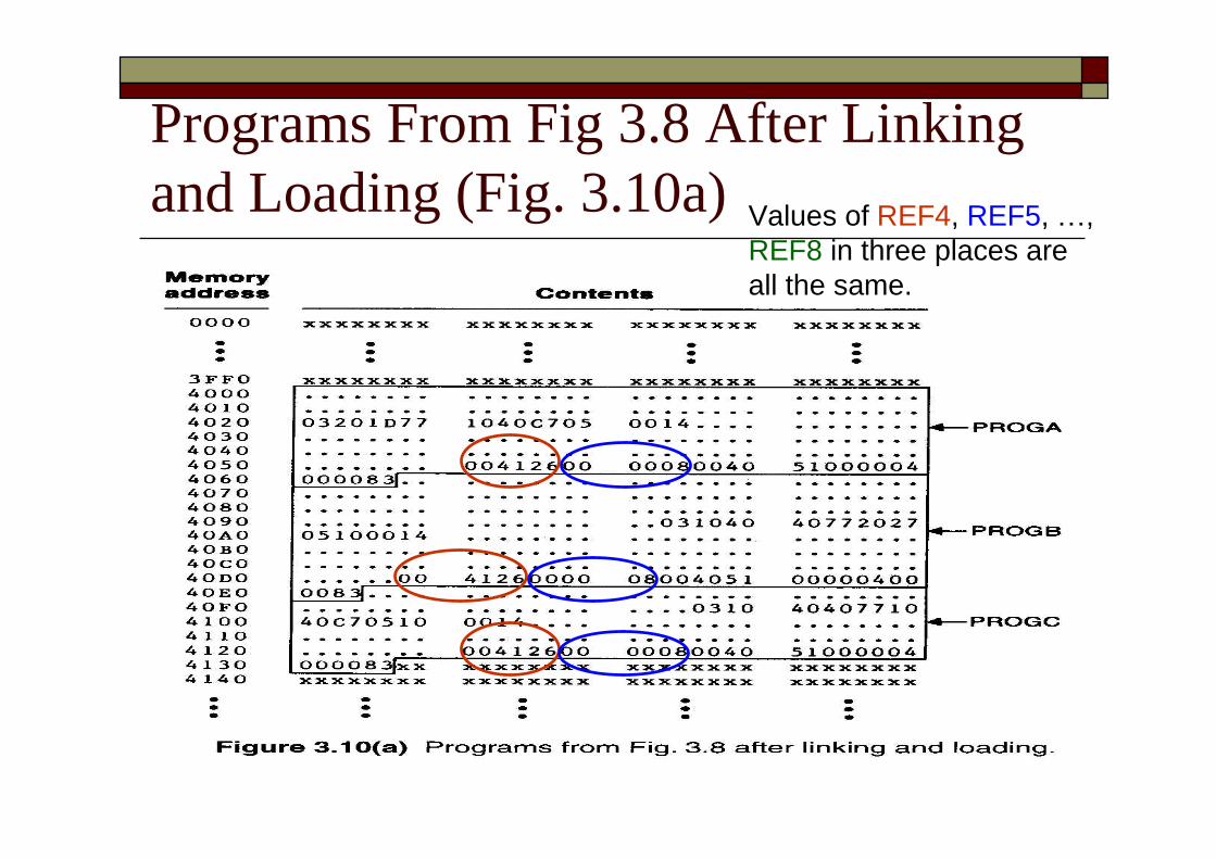
Programs From Fig 3.8 After Linkingand Loading (Fig. 3.10a) Values of REF4, REF5, …,
REF8 in three places areall the same.
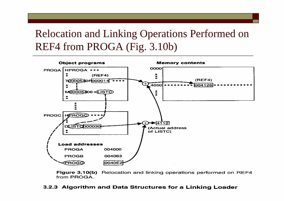
Relocation and Linking Operations Performed onREF4 from PROGA (Fig. 3.10b)
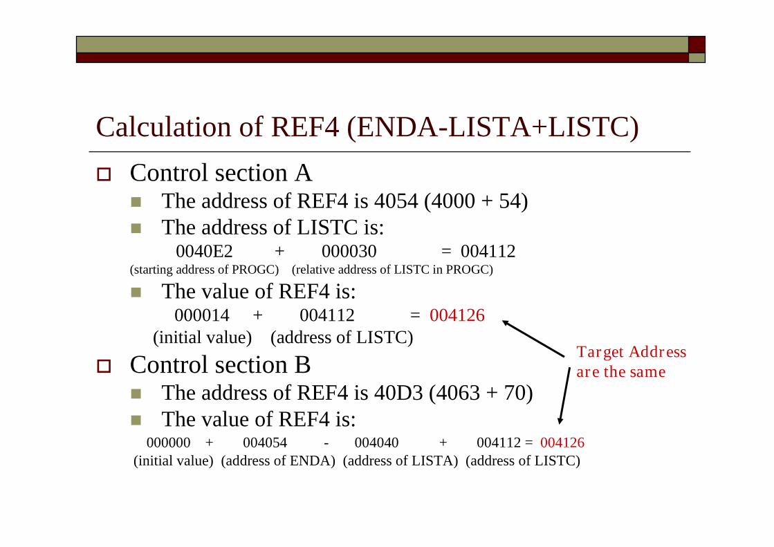
Calculation of REF4 (ENDA-LISTA+LISTC) Control section A
The address of REF4 is 4054 (4000 + 54) The address of LISTC is:
0040E2 + 000030 = 004112(starting address of PROGC) (relative address of LISTC in PROGC)
The value of REF4 is:000014 + 004112 = 004126
(initial value) (address of LISTC)
Control section B The address of REF4 is 40D3 (4063 + 70) The value of REF4 is:
000000 + 004054 - 004040 + 004112 = 004126(initial value) (address of ENDA) (address of LISTA) (address of LISTC)
Target Addressare the same
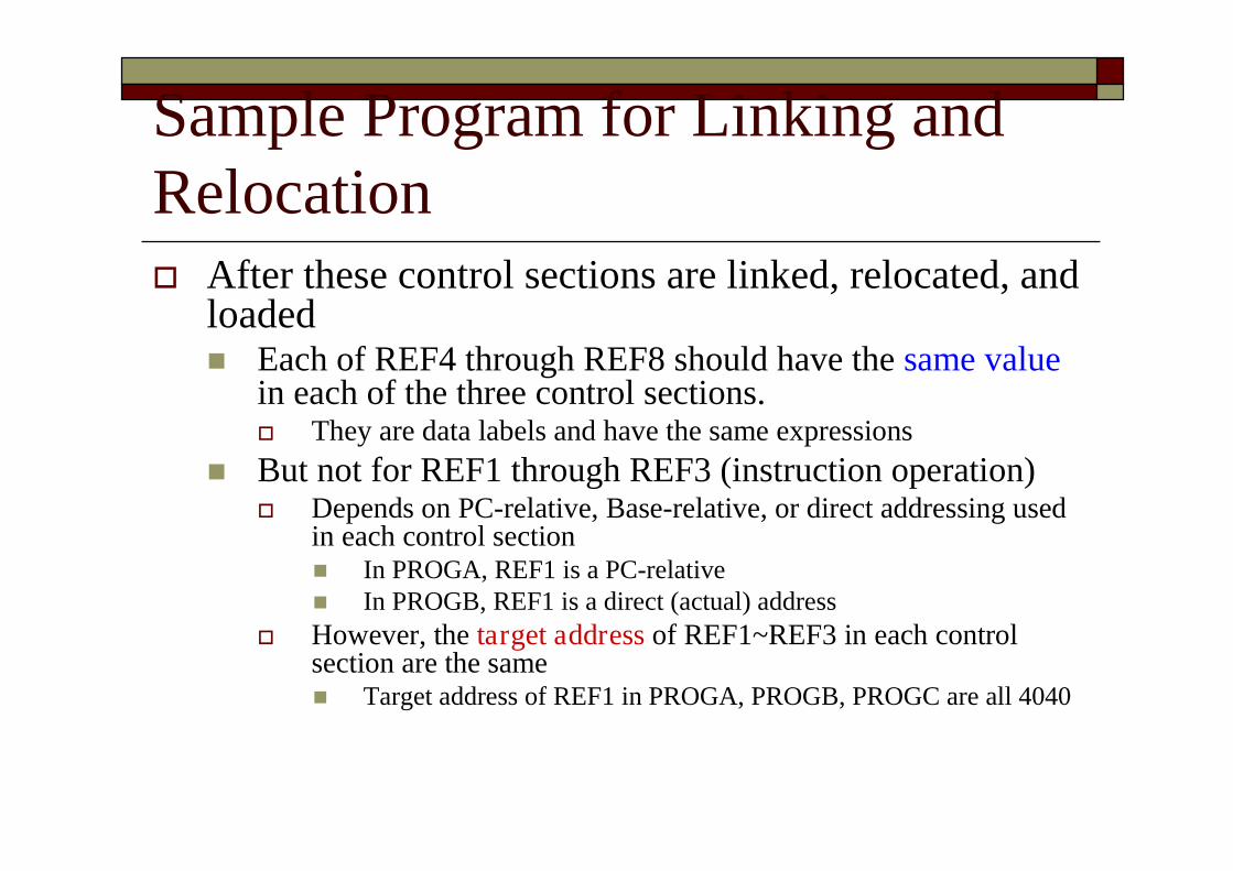
Sample Program for Linking andRelocation After these control sections are linked, relocated, and
loaded Each of REF4 through REF8 should have the same value
in each of the three control sections. They are data labels and have the same expressions
But not for REF1 through REF3 (instruction operation) Depends on PC-relative, Base-relative, or direct addressing used
in each control section In PROGA, REF1 is a PC-relative In PROGB, REF1 is a direct (actual) address
However, the target address of REF1~REF3 in each controlsection are the same Target address of REF1 in PROGA, PROGB, PROGC are all 4040

3.2.3 Algorithm and Data Structure fora Linking Loader Algorithm for a linking (and relocating) loader Modification records are used for relocation
Not use the modification bits So that linking and relocation functions are performed
using the same mechanism.
This type of loader is often found on machines(e.g. SIC/XE) Whose relative addressing makes relocation
unnecessary for most instructions.
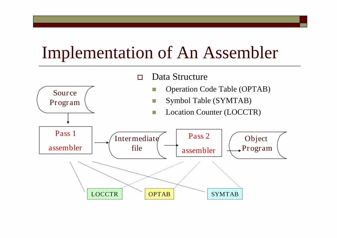
Implementation of An Assembler
Pass 1
assemblerPass 2
assemblerIntermediate
file
OPTAB SYMTABLOCCTR
SourceProgram
ObjectProgram
Data Structure Operation Code Table (OPTAB) Symbol Table (SYMTAB) Location Counter (LOCCTR)
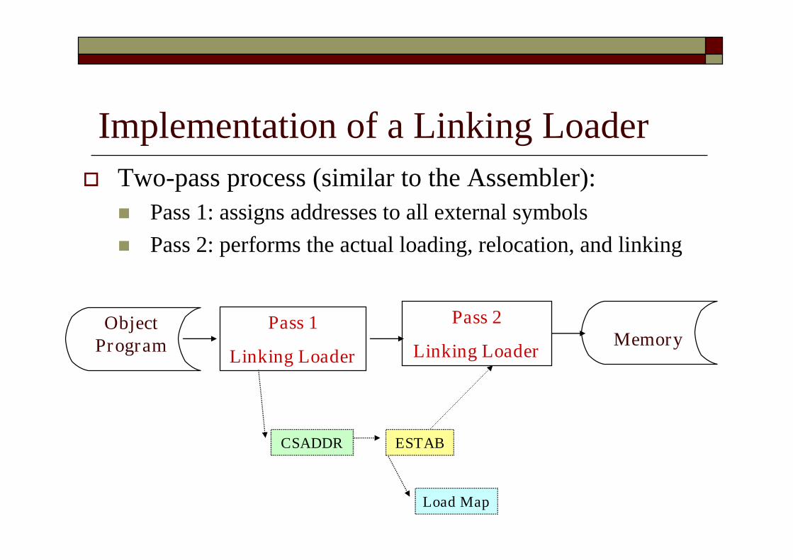
Implementation of a Linking Loader
Pass 1
Linking Loader
Pass 2
Linking Loader
ESTAB
Load Map
CSADDR
ObjectProgram Memory
Two-pass process (similar to the Assembler): Pass 1: assigns addresses to all external symbols Pass 2: performs the actual loading, relocation, and linking

Algorithm for a Linking Loader Input is a set of object programs, i.e., control
sections
A linking loader usually makes two passesover its input, just as an assembler does Pass 1: assign addresses to all external symbols
Pass 2: perform the actual loading, relocation, andlinking
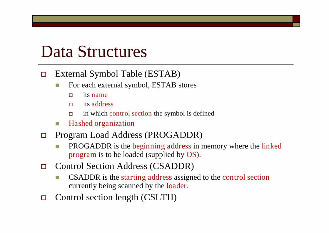
Data Structures External Symbol Table (ESTAB)
For each external symbol, ESTAB stores its name its address in which control section the symbol is defined
Hashed organization
Program Load Address (PROGADDR) PROGADDR is the beginning address in memory where the linked
program is to be loaded (supplied by OS).
Control Section Address (CSADDR) CSADDR is the starting address assigned to the control section
currently being scanned by the loader.
Control section length (CSLTH)
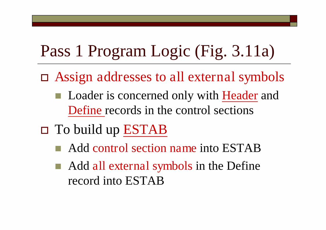
Pass 1 Program Logic (Fig. 3.11a) Assign addresses to all external symbols Loader is concerned only with Header and
Define records in the control sections
To build up ESTAB Add control section name into ESTAB Add all external symbols in the Define
record into ESTAB

(only Header and Define records are concerned)

Load Map ESTAB (External Symbol Table) may also look like Load MAP
+
+

Pass 2 Program Logic (Fig. 3.11b) Perform the actual loading, relocation, and linking When Text record is encountered
Read into the specified address (+CSADDR) When Modification record is encountered
Lookup the symbol in ESTAB This value is then added to or subtracted from the
indicated location in memory When the End record is encountered
Transfer control to the loaded program to begin execution Fig. 3.11(b)
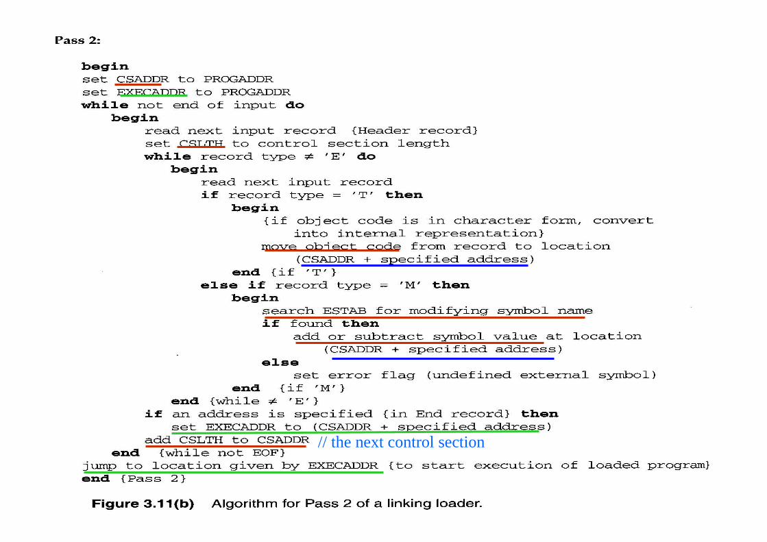
// the next control section
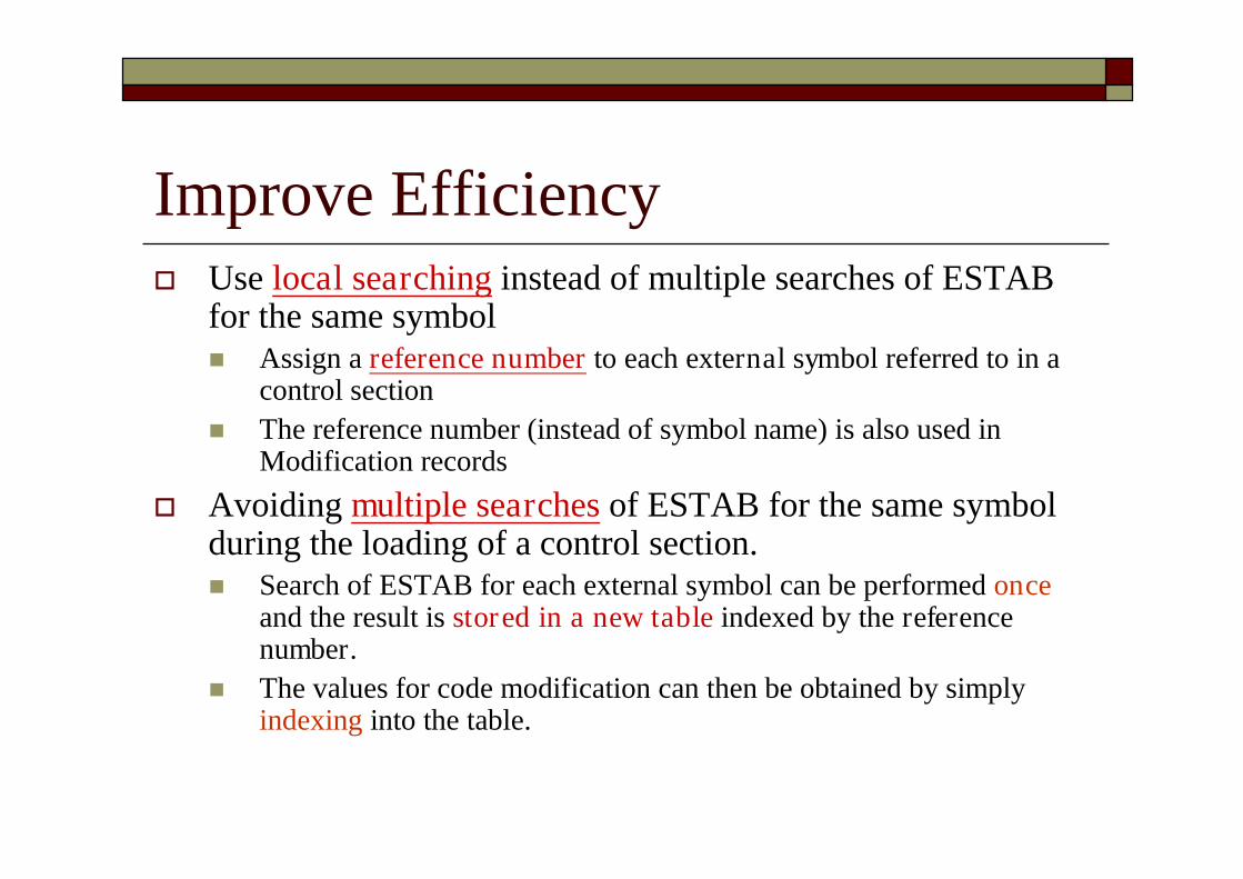
Improve Efficiency Use local searching instead of multiple searches of ESTAB
for the same symbol Assign a reference number to each external symbol referred to in a
control section The reference number (instead of symbol name) is also used in
Modification records
Avoiding multiple searches of ESTAB for the same symbolduring the loading of a control section. Search of ESTAB for each external symbol can be performed once
and the result is stored in a new table indexed by the referencenumber.
The values for code modification can then be obtained by simplyindexing into the table.
Improve Efficiency (Cont.) Implementation 01: control section name other: external reference symbols
Example Fig. 3.12

Object Programs Corresponding to Fig. 3.8 UsingReference Numbers for Code Modification (Fig. 3.12)
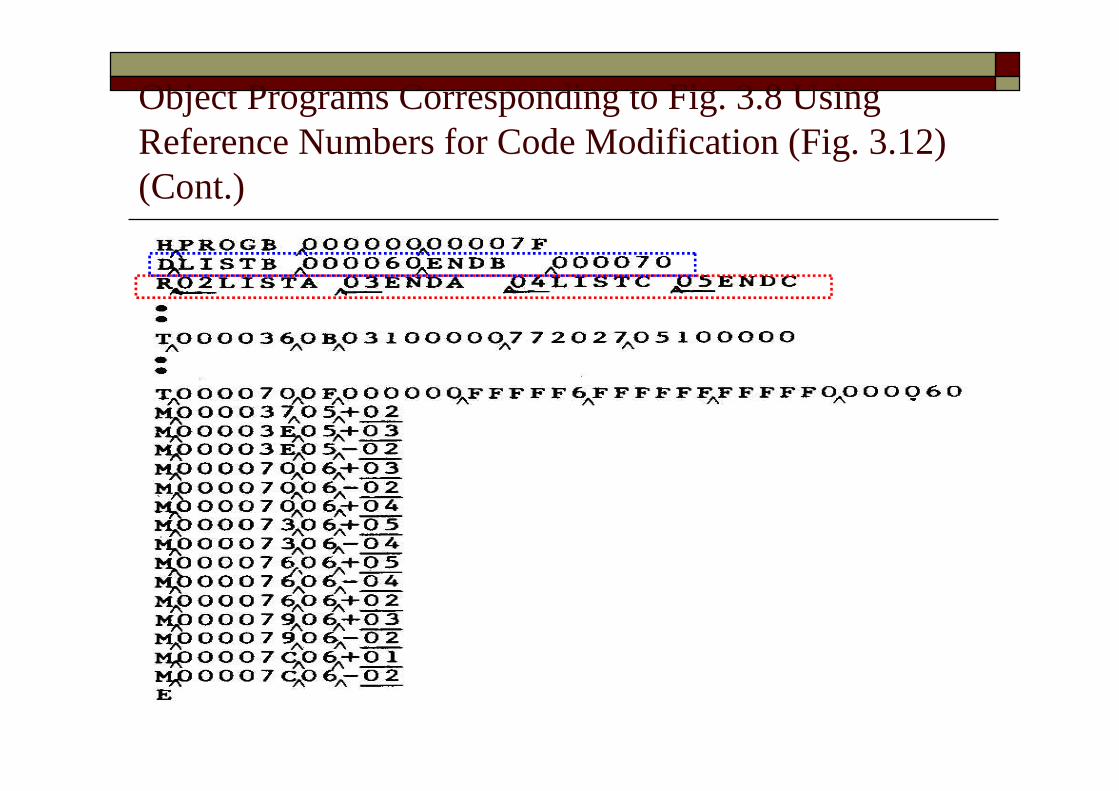
Object Programs Corresponding to Fig. 3.8 UsingReference Numbers for Code Modification (Fig. 3.12)(Cont.)
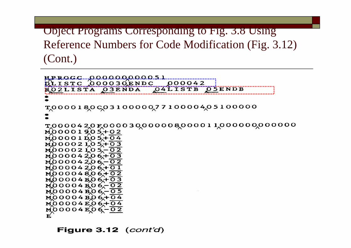
Object Programs Corresponding to Fig. 3.8 UsingReference Numbers for Code Modification (Fig. 3.12)(Cont.)

New Table for Figure 3.12Ref No. Symbol Address
1 PROGA 4000
2 LISTB 40C3
3 ENDB 40D3
4 LISTC 4112
5 ENDC 4124
Ref No. Symbol Address1 PROGB 4063
2 LISTA 4040
3 ENDA 4054
4 LISTC 4112
5 ENDC 4124
Ref No. Symbol Address1 PROGC 4063
2 LISTA 4040
3 ENDA 4054
4 LISTB 40C3
5 ENDB 40D3
PROGA
PROGB PROGC


![[ KLIKNIJ I WPISZ NAZWĘ PRZEDMIOTU ] … · The introduction to object-oriented methods and the object data structures. TEACHING METHODS: Accessible lecture in electronic form; the](https://img.pdfslide.tips/doc/110x75/5f20f2a019108c0ccc48f36f/-kliknij-i-wpisz-nazw-przedmiotu-the-introduction-to-object-oriented-methods.jpg)