Embed Size (px)
Citation preview
© 2008 Cisco Systems, Inc. All rights reserved. Cisco Confidential Presentation_ID 1
Chapter 7: Laptops
IT Essentials 5.0
Presentation_ID 2 © 2008 Cisco Systems, Inc. All rights reserved. Cisco Confidential
Chapter 7 Objectives 7.1 Describe the use and advantages of laptops.
7.2 Identify and describe the display components of a laptop .
7.3 Identify and describe how to manage laptop power settings and options.
7.4 Identify and configure laptop wireless adapters and settings.
7.5 Identify and describe laptop hardware component installation and configuration.
7.6 Identify common preventive maintenance techniques used for laptops.
7.7 Describe how to troubleshoot laptops.
Presentation_ID 3 © 2008 Cisco Systems, Inc. All rights reserved. Cisco Confidential
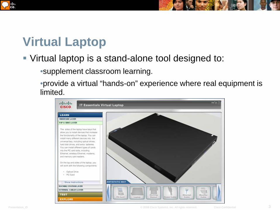
Virtual Laptop Virtual laptop is a stand-alone tool designed to:
•supplement classroom learning. •provide a virtual “hands-on” experience where real equipment is limited.
Presentation_ID 4 © 2008 Cisco Systems, Inc. All rights reserved. Cisco Confidential
Laptops Notebooks and laptops are types of portable
computers.
The most significant feature of a laptop is its compact size. The design of the laptop places the keyboard, screen, and internal components into a small, portable case.
Laptops can be used to take notes in school, present information in a business meeting, or access the Internet in a coffee shop.
Presentation_ID 5 © 2008 Cisco Systems, Inc. All rights reserved. Cisco Confidential
Components of a laptop Common laptop features:
• Integrated display screen in lid • Integrated keyboard •AC power source or rechargeable battery •Hot-swappable drives and peripherals •PC Card or ExpressCard slots •Status indicators, ports, slots, connectors, bays, jacks, vents, and a keyhole are on the exterior of the laptop
Presentation_ID 6 © 2008 Cisco Systems, Inc. All rights reserved. Cisco Confidential
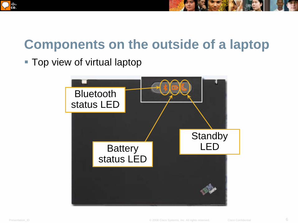
Components on the outside of a laptop Top view of virtual laptop
Bluetooth status LED
Battery status LED
Standby LED
Presentation_ID 7 © 2008 Cisco Systems, Inc. All rights reserved. Cisco Confidential
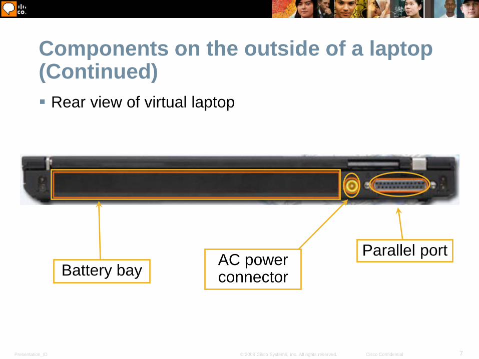
Components on the outside of a laptop (Continued) Rear view of virtual laptop
AC power connector
Parallel port Battery bay
Presentation_ID 8 © 2008 Cisco Systems, Inc. All rights reserved. Cisco Confidential
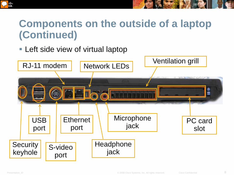
Components on the outside of a laptop (Continued) Left side view of virtual laptop
Security keyhole
USB port
S-video port
Headphone jack
Microphone jack
PC card slot
Ventilation grill RJ-11 modem
Ethernet port
Network LEDs
Presentation_ID 9 © 2008 Cisco Systems, Inc. All rights reserved. Cisco Confidential
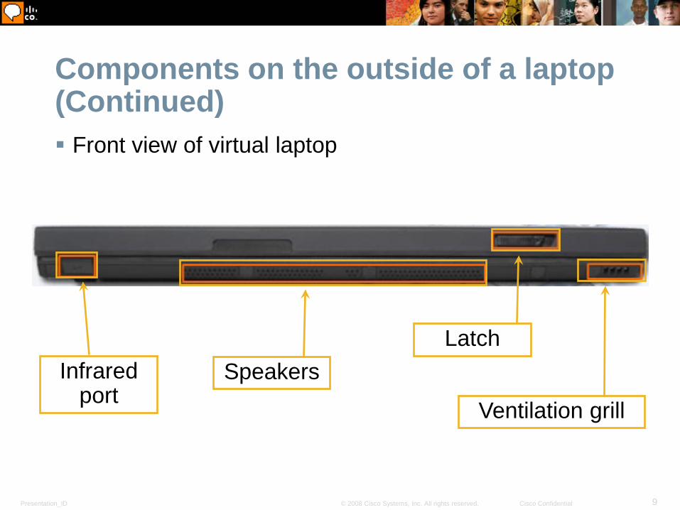
Components on the outside of a laptop (Continued) Front view of virtual laptop
Infrared port
Speakers Latch
Ventilation grill
Presentation_ID 10 © 2008 Cisco Systems, Inc. All rights reserved. Cisco Confidential
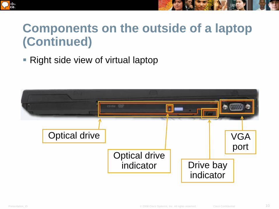
Components on the outside of a laptop (Continued) Right side view of virtual laptop
Optical drive
Optical drive indicator
VGA port
Drive bay indicator
Presentation_ID 11 © 2008 Cisco Systems, Inc. All rights reserved. Cisco Confidential
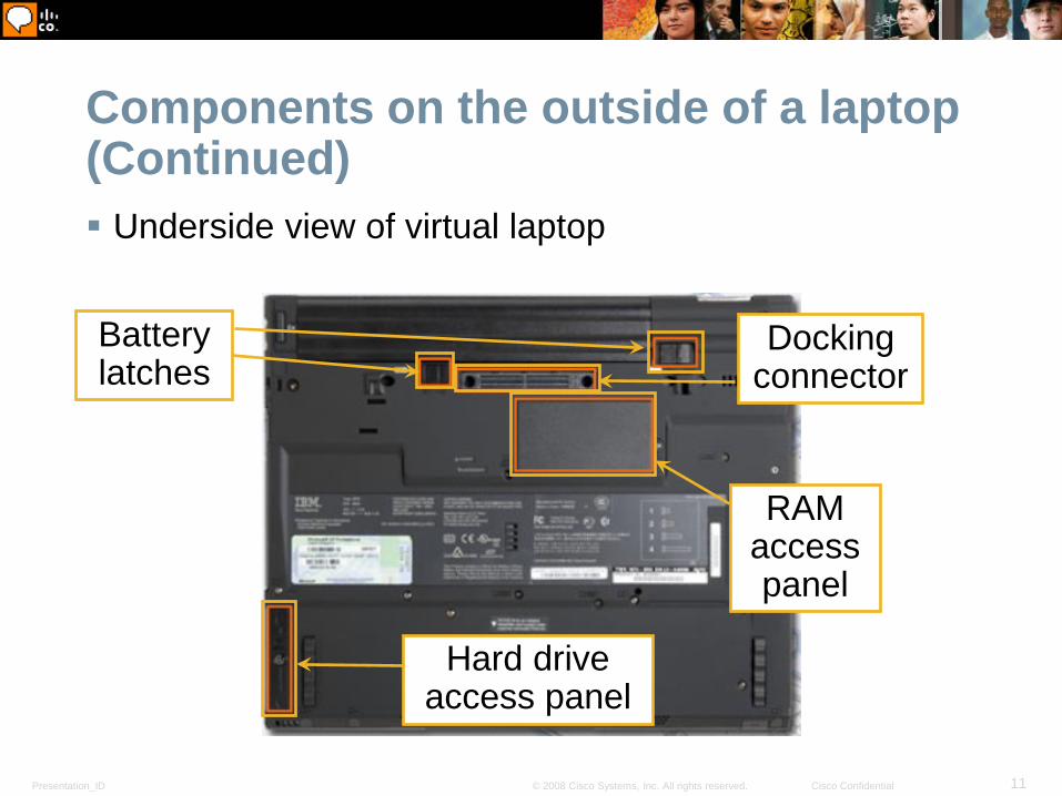
Components on the outside of a laptop (Continued) Underside view of virtual laptop
Hard drive access panel
Battery latches
Docking connector
RAM access panel
Presentation_ID 12 © 2008 Cisco Systems, Inc. All rights reserved. Cisco Confidential
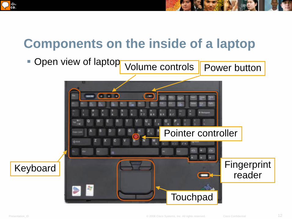
Components on the inside of a laptop Open view of laptop
Keyboard
Volume controls Power button
Touchpad
Pointer controller
Fingerprint reader
Presentation_ID 13 © 2008 Cisco Systems, Inc. All rights reserved. Cisco Confidential
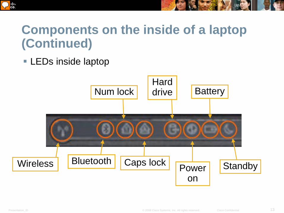
Components on the inside of a laptop (Continued) LEDs inside laptop
Wireless Bluetooth Caps lock
Num lock Hard drive Battery
Power on
Standby
Presentation_ID 14 © 2008 Cisco Systems, Inc. All rights reserved. Cisco Confidential
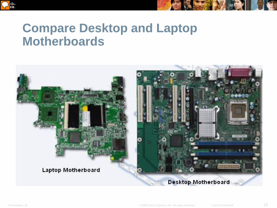
Compare Desktop and Laptop Motherboards
Presentation_ID 15 © 2008 Cisco Systems, Inc. All rights reserved. Cisco Confidential
Laptop Components - Laptop CPU Laptop processors are designed to use less power
and create less heat than desktop processors. As a result, laptop processors do not require cooling devices that are as large as those found in desktops.
Laptop processors also use CPU throttling to modify the clock speed as needed to reduce power consumption and heat. These specially-designed processors allow a laptop to operate longer when using a battery.
Presentation_ID 16 © 2008 Cisco Systems, Inc. All rights reserved. Cisco Confidential
Laptop Components (Continued) Monitor, Fn key, and Function keys F1 through F12
A laptop monitor is a built-in LCD. A desktop monitor can be added to a laptop.
The Fn key is used to activate a second function on a dual-purpose key.
• The feature that is accessed by pressing the Fn key in combination with another key is printed on the key in a smaller font or different color.
The purpose of the Function keys F1-to-F12 depends on the operating system and the application running.
Presentation_ID 17 © 2008 Cisco Systems, Inc. All rights reserved. Cisco Confidential
Laptop Components (Continued)
Port Replicator - may contain a SCSI port, a networking port, PS/2 ports, USB ports, and a game port.
• Docking Station - has the same ports as a port replicator, but adds the ability to connect to PCI cards, additional hard drives, optical drives, and floppy drives.
•A laptop connected to a docking station has the same functionalities as a desktop computer.
Presentation_ID 18 © 2008 Cisco Systems, Inc. All rights reserved. Cisco Confidential
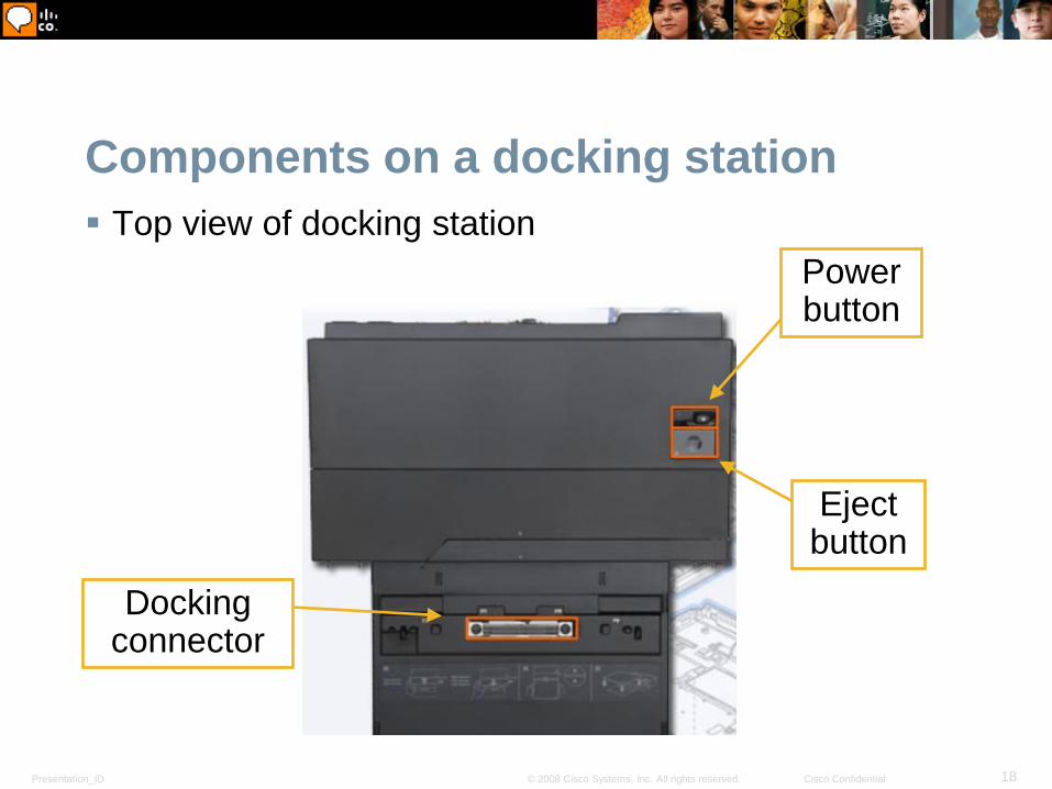
Components on a docking station Top view of docking station
Docking connector
Power button
Eject button
Presentation_ID 19 © 2008 Cisco Systems, Inc. All rights reserved. Cisco Confidential
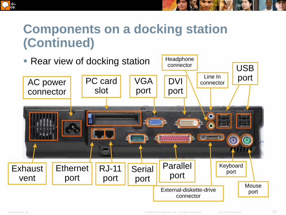
Components on a docking station (Continued) Rear view of docking station
Exhaust vent
AC power connector
PC card slot
Ethernet port
RJ-11 port
Serial port
VGA port
Parallel port
DVI port
External-diskette-drive connector
Headphone connector
Line In connector
USB port
Keyboard port
Mouse port
Presentation_ID 20 © 2008 Cisco Systems, Inc. All rights reserved. Cisco Confidential
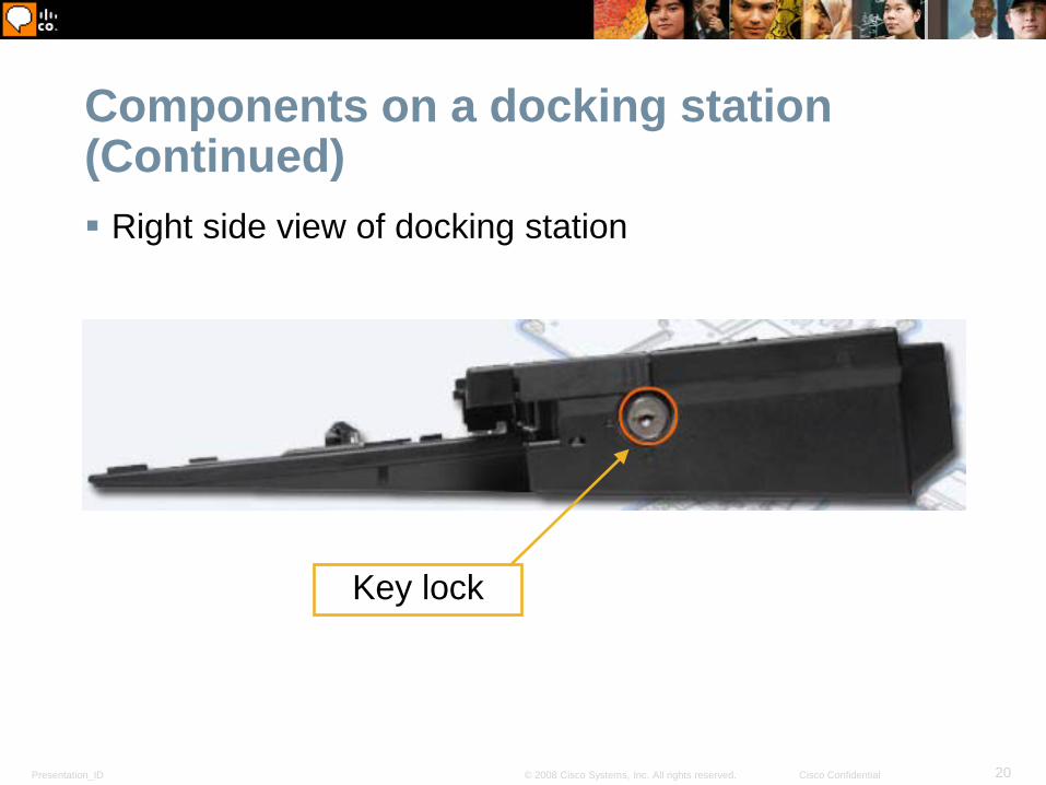
Components on a docking station (Continued) Right side view of docking station
Key lock
Presentation_ID 21 © 2008 Cisco Systems, Inc. All rights reserved. Cisco Confidential
Laptop Display Types Laptop monitors are built-in displays. There are four
types of laptop displays:
LCD - Liquid Crystal Display
LED – Light Emitting Diode - uses less power and has a longer lifespan than LCD monitors
OLED - Organic LED
Plasma – rarely used in laptops due to high power consumption
Presentation_ID 22 © 2008 Cisco Systems, Inc. All rights reserved. Cisco Confidential
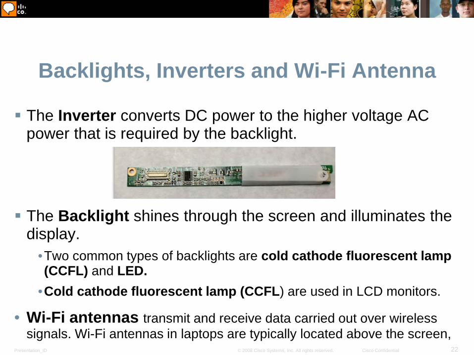
Backlights, Inverters and Wi-Fi Antenna
The Inverter converts DC power to the higher voltage AC power that is required by the backlight.
The Backlight shines through the screen and illuminates the display.
•Two common types of backlights are cold cathode fluorescent lamp (CCFL) and LED.
•Cold cathode fluorescent lamp (CCFL) are used in LCD monitors.
• Wi-Fi antennas transmit and receive data carried out over wireless signals. Wi-Fi antennas in laptops are typically located above the screen,
Presentation_ID 23 © 2008 Cisco Systems, Inc. All rights reserved. Cisco Confidential
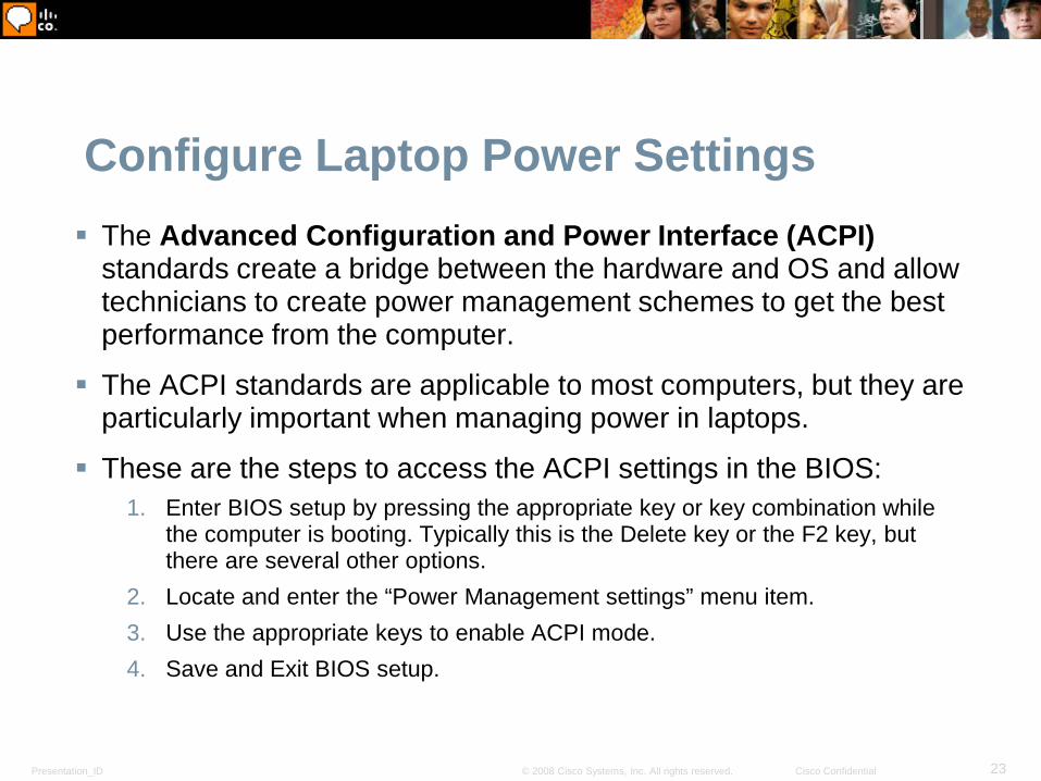
Configure Laptop Power Settings The Advanced Configuration and Power Interface (ACPI)
standards create a bridge between the hardware and OS and allow technicians to create power management schemes to get the best performance from the computer.
The ACPI standards are applicable to most computers, but they are particularly important when managing power in laptops.
These are the steps to access the ACPI settings in the BIOS: 1. Enter BIOS setup by pressing the appropriate key or key combination while
the computer is booting. Typically this is the Delete key or the F2 key, but there are several other options.
2. Locate and enter the “Power Management settings” menu item. 3. Use the appropriate keys to enable ACPI mode. 4. Save and Exit BIOS setup.
Presentation_ID 24 © 2008 Cisco Systems, Inc. All rights reserved. Cisco Confidential
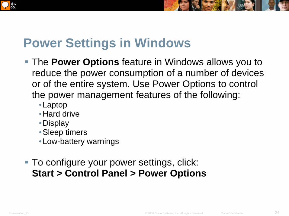
Power Settings in Windows The Power Options feature in Windows allows you to
reduce the power consumption of a number of devices or of the entire system. Use Power Options to control the power management features of the following:
•Laptop •Hard drive •Display •Sleep timers •Low-battery warnings
To configure your power settings, click: Start > Control Panel > Power Options
Presentation_ID 25 © 2008 Cisco Systems, Inc. All rights reserved. Cisco Confidential
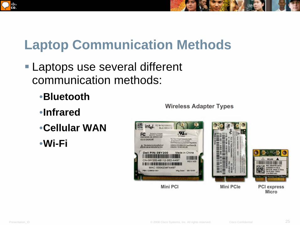
Laptop Communication Methods Laptops use several different
communication methods: •Bluetooth •Infrared •Cellular WAN •Wi-Fi
Presentation_ID 26 © 2008 Cisco Systems, Inc. All rights reserved. Cisco Confidential
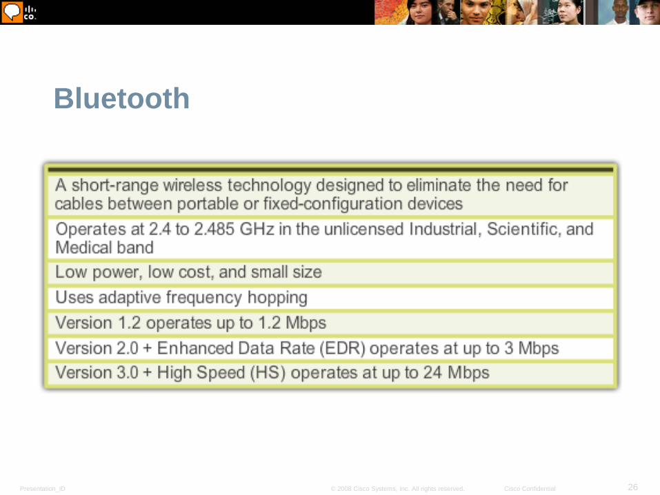
Bluetooth
Presentation_ID 27 © 2008 Cisco Systems, Inc. All rights reserved. Cisco Confidential
Infrared
A short-range, low-throughput wireless technology used as a data transmission medium.
Infrared light signals operate in the lowest light frequency.
Distances are limited to a few feet or meters.
IR cannot penetrate any object that blocks the light signal.
Three types of IR networks: • Line of sight - The signal is transmitted only if there is a clear, unobstructed view between devices.
• Scatter - The signal is bounced off ceilings and walls. • Reflective - The signal is sent to an optical transceiver and is redirected to the receiving device.
Presentation_ID 28 © 2008 Cisco Systems, Inc. All rights reserved. Cisco Confidential
Cellular WAN
To connect a laptop to a cellular WAN, you install an adapter that is designed to work with cellular networks.
•Cellular WAN cards are plug-and-play. • Can be plugged in to the PC card slot or is built in to the laptop.
•Also, access with a USB adapter or by using a mobile hotspot.
Laptops with integrated cellular WAN capabilities require no software installation and no additional antenna or accessories.
Presentation_ID 29 © 2008 Cisco Systems, Inc. All rights reserved. Cisco Confidential
Wi-Fi
Wi-Fi is a wireless technology that provides a simple connection from anywhere within the range of a base station.
Connection distances of 300 feet (91 meters) or more, depending on the environment.
Ease of access makes Wi-Fi a simple solution for network connectivity.
Presentation_ID 30 © 2008 Cisco Systems, Inc. All rights reserved. Cisco Confidential
Wi-Fi Laptops access the internet by using wireless adapters
Mini-PCI - Commonly used by older laptops. Mini-PCI cards have 124 pins and are capable of 802.11a, 802.11b and 802.11g wireless LAN connection standards.
Mini-PCIe - Most common type of wireless card in laptops. Mini-PCIe cards have 54 pins and support all wireless LAN standards.
PCI Express Micro - Commonly found in newer and smaller laptops, such as Ultrabooks, because they are half the size of Mini-PCIe cards.
Presentation_ID 31 © 2008 Cisco Systems, Inc. All rights reserved. Cisco Confidential
Laptop Expansion Options
PC Card or ExpressCard slots used to add functionality such as:
• Wi-Fi connectivity • Ethernet access • USB and FireWire ports • External hard drive access • Additional memory
ExpressCard is the newer model of expansion card and is most commonly used:
• ExpressCard /34 - 34 mm wide • ExpressCard /54 - 54 mm wide
Presentation_ID 32 © 2008 Cisco Systems, Inc. All rights reserved. Cisco Confidential
Laptop Expansion Options
Flash Memory •External Flash Drive •Flash Cards and Flash Card Readers
SODIMM - smaller profile memory chip used by laptops •72-pin and 100-pin configurations for support of 32-bit transfers. •144-pin, 200-pin, and 204-pin configurations for support of 64-bit transfers.
Note: Before purchasing and installing additional RAM, consult the laptop documentation or the website of the manufacturer for form-factor specifications.
Presentation_ID 33 © 2008 Cisco Systems, Inc. All rights reserved. Cisco Confidential
Replacing Hardware Devices
Customer Replaceable Units (CRUs) can be replaced by the customer.
Field Replaceable Units (FRUs) should only be replaced by a qualified field technician typically in a repair center. Repairs include:
• Hardware and software diagnostics • Data transfer and recovery • Hard drive installation and upgrades • RAM installation and upgrades • Keyboard and fan replacement • Internal laptop cleaning • LCD screen repair • LCD inverter and backlight repair
Presentation_ID 34 © 2008 Cisco Systems, Inc. All rights reserved. Cisco Confidential
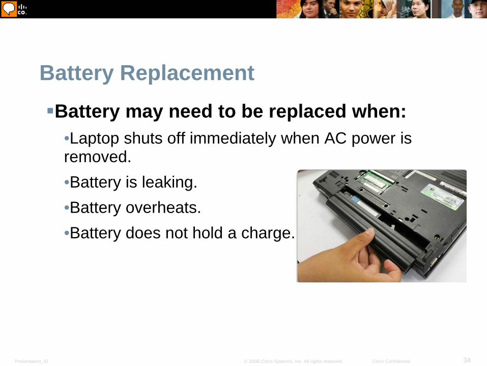
Battery Replacement Battery may need to be replaced when:
•Laptop shuts off immediately when AC power is removed. •Battery is leaking. •Battery overheats. •Battery does not hold a charge.
Presentation_ID 35 © 2008 Cisco Systems, Inc. All rights reserved. Cisco Confidential
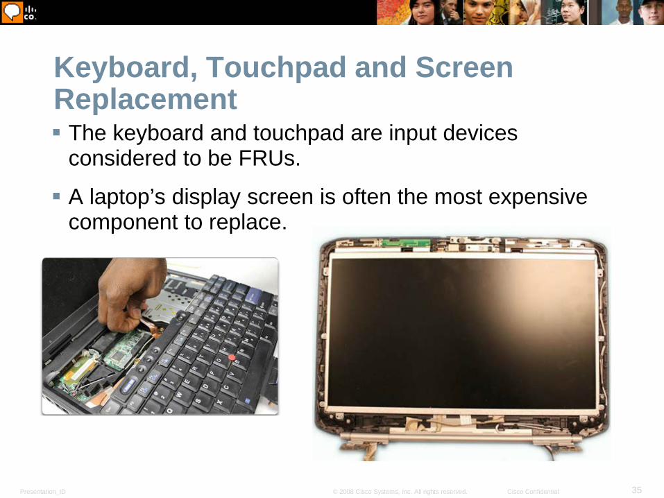
Keyboard, Touchpad and Screen Replacement The keyboard and touchpad are input devices
considered to be FRUs.
A laptop’s display screen is often the most expensive component to replace.
Presentation_ID 36 © 2008 Cisco Systems, Inc. All rights reserved. Cisco Confidential
Hard Drive and Optical Drive Replacement Storage devices are CRUs, unless a warranty requires
technical assistance.
Laptop hard drives are 1.8 in. (4.57 cm.) or 2.5 in. (6.35 cm.) in width.
External USB hard drive connects to a laptop using the USB port.
IEEE 1394 external hard drive connects to the FireWire port.
Presentation_ID 37 © 2008 Cisco Systems, Inc. All rights reserved. Cisco Confidential
Replacing Hardware Devices
Before replacing a wireless card, determine which form factor is required by the laptop.
Before a CPU can be replaced, the technician must remove the fan and heat sink.
•NOTE: A CPU is one of the most fragile components in a laptop. It should be handled with great care.
Before replacing a laptop motherboard, make sure that the replacement meets the design specifications of the laptop model.
Presentation_ID 38 © 2008 Cisco Systems, Inc. All rights reserved. Cisco Confidential
Preventive Maintenance Techniques
The Preventive Maintenance Schedule for laptops should include these standard procedures:
•Cleaning •Hard drive maintenance •Software updates
The most effective preventive maintenance programs require a set of routines to be conducted monthly.
Presentation_ID 39 © 2008 Cisco Systems, Inc. All rights reserved. Cisco Confidential
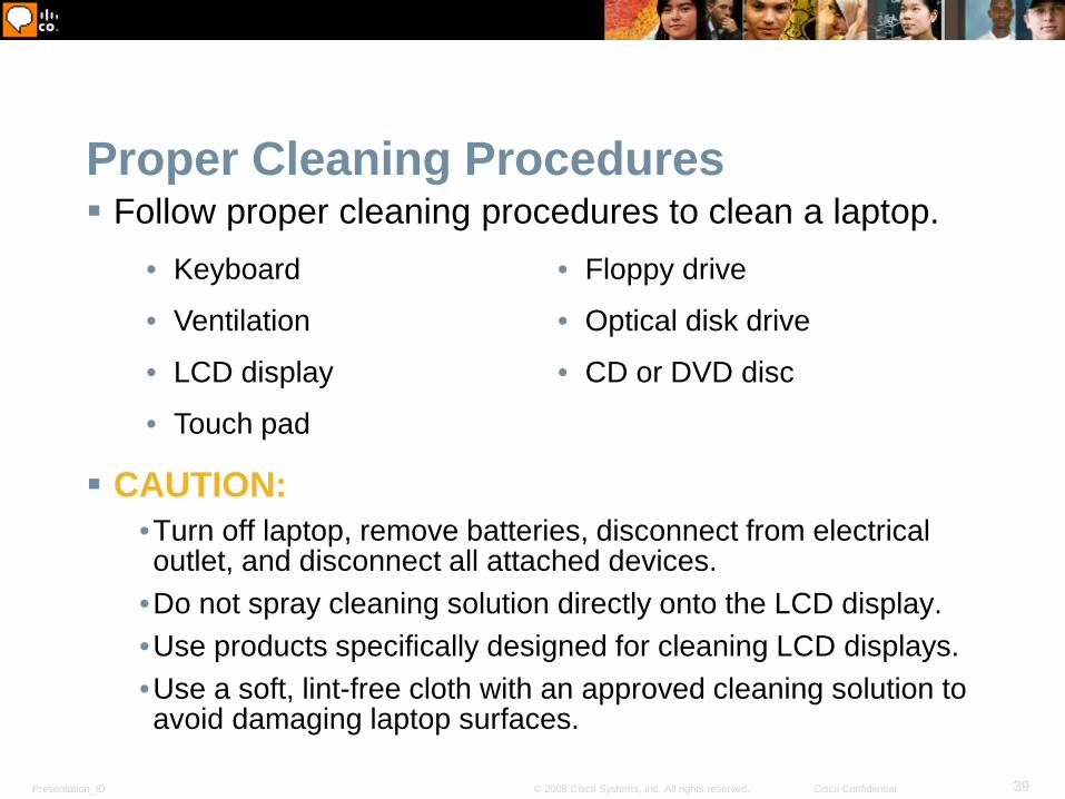
Proper Cleaning Procedures Follow proper cleaning procedures to clean a laptop.
CAUTION: •Turn off laptop, remove batteries, disconnect from electrical outlet, and disconnect all attached devices.
•Do not spray cleaning solution directly onto the LCD display. •Use products specifically designed for cleaning LCD displays. •Use a soft, lint-free cloth with an approved cleaning solution to avoid damaging laptop surfaces.
• Keyboard
• Ventilation
• LCD display
• Touch pad
• Floppy drive
• Optical disk drive
• CD or DVD disc
Presentation_ID 40 © 2008 Cisco Systems, Inc. All rights reserved. Cisco Confidential
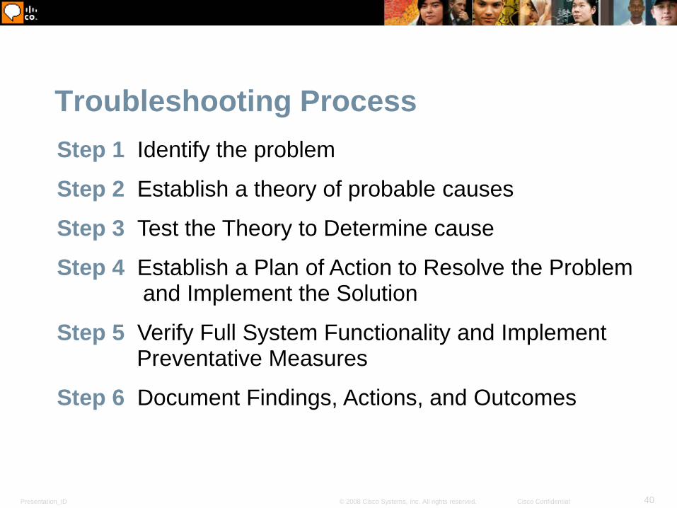
Troubleshooting Process Step 1 Identify the problem Step 2 Establish a theory of probable causes Step 3 Test the Theory to Determine cause Step 4 Establish a Plan of Action to Resolve the Problem
and Implement the Solution Step 5 Verify Full System Functionality and Implement
Preventative Measures Step 6 Document Findings, Actions, and Outcomes
Presentation_ID 41 © 2008 Cisco Systems, Inc. All rights reserved. Cisco Confidential
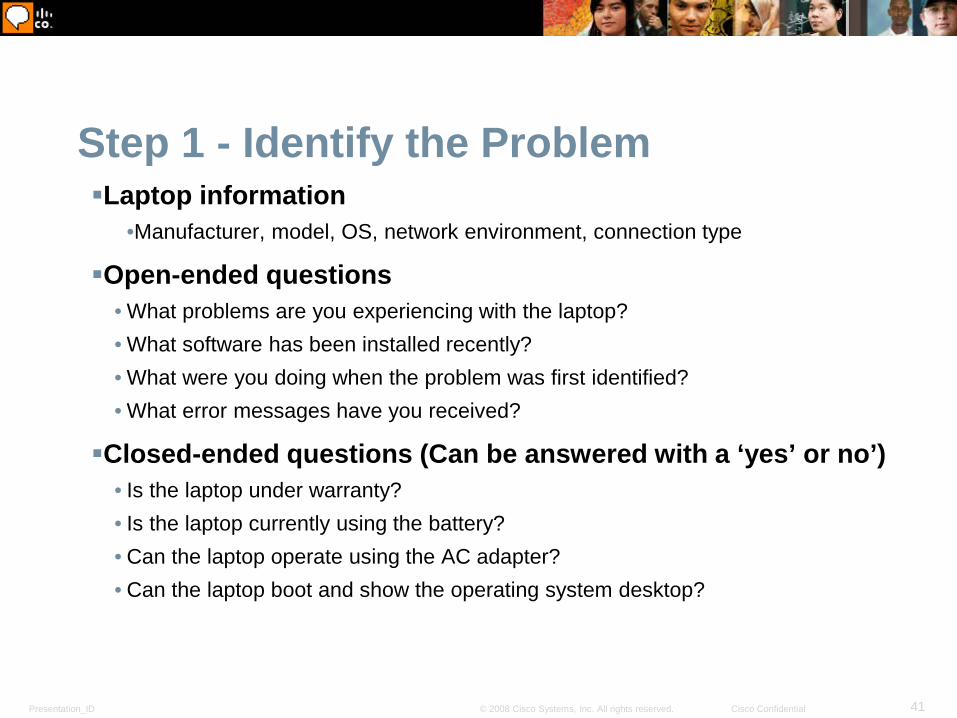
Step 1 - Identify the Problem Laptop information
•Manufacturer, model, OS, network environment, connection type
Open-ended questions • What problems are you experiencing with the laptop? • What software has been installed recently? • What were you doing when the problem was first identified? • What error messages have you received?
Closed-ended questions (Can be answered with a ‘yes’ or no’) • Is the laptop under warranty? • Is the laptop currently using the battery? • Can the laptop operate using the AC adapter? • Can the laptop boot and show the operating system desktop?
Presentation_ID 42 © 2008 Cisco Systems, Inc. All rights reserved. Cisco Confidential
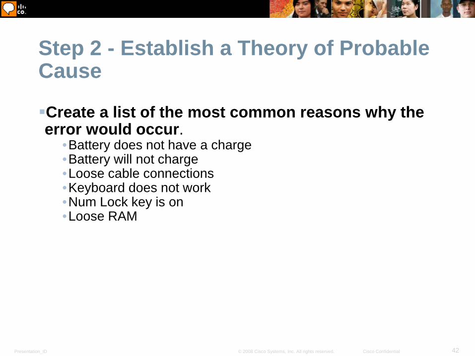
Step 2 - Establish a Theory of Probable Cause Create a list of the most common reasons why the error would occur.
•Battery does not have a charge •Battery will not charge •Loose cable connections •Keyboard does not work •Num Lock key is on •Loose RAM
Presentation_ID 43 © 2008 Cisco Systems, Inc. All rights reserved. Cisco Confidential
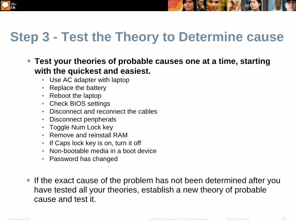
Test your theories of probable causes one at a time, starting with the quickest and easiest.
• Use AC adapter with laptop • Replace the battery • Reboot the laptop • Check BIOS settings • Disconnect and reconnect the cables • Disconnect peripherals • Toggle Num Lock key • Remove and reinstall RAM • If Caps lock key is on, turn it off • Non-bootable media in a boot device • Password has changed
If the exact cause of the problem has not been determined after you have tested all your theories, establish a new theory of probable cause and test it.
Step 3 - Test the Theory to Determine cause
Presentation_ID 44 © 2008 Cisco Systems, Inc. All rights reserved. Cisco Confidential
If a quick procedure does not correct the problem, you might need to research the problem further to establish the exact cause.
Divide larger problems into smaller problems that can be analyzed and solved individually.
Create a list of possible solutions and implement them one at a time. If you implement a possible solution and it does not work, reverse the solution and try another.
Step 4 - Establish a Plan of Action to Resolve the Problem and Implement the Solution
Presentation_ID 45 © 2008 Cisco Systems, Inc. All rights reserved. Cisco Confidential
Verify full system functionality and implement any preventive measures if needed. This ensures that you have not created another problem while repairing the computer.
• Reboot the laptop • Attach all peripherals • Operate laptop using only battery • Print a document from an application • Type sample document to test keyboard • Check Event Viewer for warnings or errors
Have the customer verify the solution and system functionality.
Step 5 - Verify Full System Functionality and Implement Preventative Measures
Presentation_ID 46 © 2008 Cisco Systems, Inc. All rights reserved. Cisco Confidential
Discuss the solution with the customer.
Have the customer confirm that the problem has been solved.
Give the customer all appropriate paperwork Document the process in the work order and in your
technician’s journal: •Problem description •Solution •Components used •Amount of time spent in solving the problem
Step 6 - Document Findings, Actions, and Outcomes
Presentation_ID 47 © 2008 Cisco Systems, Inc. All rights reserved. Cisco Confidential
Common Problems and Solutions Laptop problems can be attributed to hardware,
software, networks, or some combination of the three. Refer to chart in curriculum –Common Problems and
Solutions 7.7.2.1.
Presentation_ID 48 © 2008 Cisco Systems, Inc. All rights reserved. Cisco Confidential
Chapter 7 Summary Laptops are becoming increasingly popular due to reduced costs, lighter
weights, increased capabilities, and longer battery power.
Laptops and desktops have ports that are virtually the same, so peripherals are interchangeable. Laptops can use docking stations or port replicators to quickly connect to desktop peripherals and AC power.
Desktop and laptop components, such as motherboards, are not interchangeable. Additionally, laptop components tend to be proprietary to each manufacturer and designed with unique form factors.
The laptop CPU is designed to use less power and create less heat than the desktop computer.
Functionality of the laptop can be expanded by adding components via PC Card or ExpressCard slots, USB, and Firewire.
Presentation_ID 49 © 2008 Cisco Systems, Inc. All rights reserved. Cisco Confidential
Chapter 7 Summary (Continued) An important component of laptop portability is the ability to run on battery
power. The current method of managing power is through the operating system with the Advanced Configuration and Power Interface (ACPI).
There are several components of a laptop that may need to be replaced. Steps are defined to replace the battery, optical drive, hard drive, memory, and PC Cards.
Preventive maintenance will ensure optimal operation of the laptop. It is important to keep the laptop clean and in safe environments. It is critical to use the correct materials and techniques when cleaning the various components of a laptop. Procedures for cleaning the components are presented.
Presentation_ID 50 © 2008 Cisco Systems, Inc. All rights reserved. Cisco Confidential
Chapter 7 Summary (Continued) Troubleshooting laptop problems requires the technician to identify, repair,
and document the problem.
Check for external problems, such as connection errors, power errors, and function key errors.
Try quick solutions first to solve laptop problems.
Resources for troubleshooting should include the following: other technicians, Internet resources, manufacturers’ FAQs, and online forums.
The final steps in the troubleshooting process are to test the laptop in all scenarios, discuss the solution with the customer, fill out all necessary paperwork and billing documents, and document the solution.

Presentation_ID 51 © 2008 Cisco Systems, Inc. All rights reserved. Cisco Confidential