Embed Size (px)
Citation preview
BUREAU OF DESIGN AND ENVIRONMENT MANUAL
Chapter Fifty-three
PAVEMENT REHABILITATION

Illinois PAVEMENT REHABILITATION July 2014
53-i HARD COPIES UNCONTROLLED
Chapter Fifty-three PAVEMENT REHABILITATION
Table of Contents
Section Page 53-1 PAVEMENT CONDITION AND DISTRESS DATA RESOURCES ......................... 53-1.1
53-1.01 Condition Rating Survey (CRS) ............................................................. 53-1.1 53-1.02 Data Collection Vehicles (DCVs) ........................................................... 53-1.1
53-1.02(a) Data Collection System .................................................. 53-1.1 53-1.02(b) Workstations and Data Access ...................................... 53-1.2 53-1.02(c) Test Requests ................................................................ 53-1.2
53-1.03 Information Databases .......................................................................... 53-1.2
53-1.03(a) Illinois Pavement Feedback System (IPFS) ................... 53-1.2 53-1.03(b) Pavement Management File (PMF) ............................... 53-1.3 53-1.03(c) Illinois Roadway Information System (IRIS) ................... 53-1.3
53-1.04 Rutting, Roughness, and Faulting Data ................................................. 53-1.3
53-1.04(a) Rutting Data ................................................................... 53-1.4 53-1.04(b) International Roughness Index (IRI) .............................. 53-1.4 53-1.04(c) Faulting Data .................................................................. 53-1.5 53-1.04(d) Data Sources ................................................................. 53-1.6
53-2 PAVEMENT DISTRESS TYPES ............................................................................. 53-2.1
53-2.01 Diagnosing Structural and Surface Distresses ...................................... 53-2.1 53-2.02 Hot-Mix Asphalt (HMA) Pavement Distresses ....................................... 53-2.2 53-2.03 Jointed Plain/Reinforced Concrete Pavement (JPCP/JRCP)
Distresses .............................................................................................. 53-2.8 53-2.04 Continuously Reinforced Concrete (CRC) Pavement Distresses .......... 53-2.15 53-2.05 Shoulder Distresses .............................................................................. 53-2.21
53-3 FIELD TESTING OF PAVEMENT STRUCTURES ................................................. 53-3.1
53-3.01 Non-Destructive vs. Destructive Testing ............................................... 53-3.1
53-3.01(a) Major Parameters of Pavement Testing......................... 53-3.1 53-3.01(b) Need for Destructive Testing.......................................... 53-3.2
53-3.02 Pavement Database Systems and Field Observations NDT ............ 53-3.3
53-3.02(a) Application of Pavement Database Systems ................. 53-3.3 53-3.02(b) Supplemental Field Observations .................................. 53-3.3
Illinois PAVEMENT REHABILITATION July 2014
53-ii HARD COPIES UNCONTROLLED
Table of Contents (Continued)
Section Page
53-3.03 Falling Weight Deflectometer (FWD) NDT ........................................ 53-3.3
53-3.03(a) FWD System .................................................................. 53-3.3 53-3.03(b) FWD System Application ............................................... 53-3.3 53-3.03(c) Application of FWD Test Data ........................................ 53-3.4 53-3.03(d) Test Requests ................................................................ 53-3.4
53-3.04 Pavement Friction Testing (PFT) NDT .............................................. 53-3.4
53-3.04(a) PFT System ................................................................... 53-3.4 53-3.04(b) PFT System Application ................................................. 53-3.4 53-3.04(c) Application of PFT Test Data ......................................... 53-3.5 53-3.04(d) Test Requests ................................................................ 53-3.5
53-3.05 Dynamic Cone Penetrometer (DCP) NDT ........................................ 53-3.5
53-3.05(a) DCP System .................................................................. 53-3.5 53-3.05(b) DCP System Application ................................................ 53-3.5 53-3.05(c) Application of DCP Test Data ........................................ 53-3.5 53-3.05(d) Test Requests ................................................................ 53-3.6
53-3.06 Destructive Testing (DT) Methods ......................................................... 53-3.6
53-3.06(a) Pavement Slab Removal ............................................... 53-3.6 53-3.06(b) Pavement Coring ........................................................... 53-3.7 53-3.06(c) Test Responsibilities ...................................................... 53-3.8
53-3.07 Application of Field Test Methods ......................................................... 53-3.8 53-3.08 Guidelines for Material Sampling and Testing of Existing
Hot-Mix Asphalt ..................................................................................... 53-3.13 53-3.08(a) Pavement Coring Process ............................................. 53-3.14 53-3.08(b) Additional Materials/Data to Collect ............................... 53-3.18 53-3.08(c) Core Sample Testing ..................................................... 53-3.19 53-3.08(d) Stripping of HMA Mixtures, Visual Identification, and
Classification .................................................................. 53-3.23 53-3.08(e) Hamburg Wheel Rut Testing .......................................... 53-3.25
53-4 PAVEMENT REHABILITATION METHODS AND STRATEGIES ........................... 53-4.1
53-4.01 Pavement Rehabilitation Methods ......................................................... 53-4.1 53-4.02 Guidelines for Selecting Pavement Rehabilitation Strategies ............... 53-4.22
53-4.02(a) Application Matrices for Rehabilitation Methods ............ 53-4.22 53-4.02(b) Rehabilitation of Bare PCC Pavements ......................... 53-4.22 53-4.02(c) Rehabilitation of HMA Overlaid PCC Pavements .......... 53-4.31
Illinois PAVEMENT REHABILITATION July 2014
53-iii HARD COPIES UNCONTROLLED
Table of Contents (Continued)
Section Page
53-4.03 3P Program ........................................................................................... 53-4.39 53-4.04 Policy Resurfacing Program and Exceptions ........................................ 53-4.41
53-4.04(a) Interstates and Freeways Built Essentially to
Interstate Criteria ........................................................... 53-4.41 53-4.04(b) Other State Maintained Highways ................................. 53-4.42 53-4.04(c) Documentation for Exception Requests ......................... 53-4.45 53-4.04(d) Waterproofing and Surfacing of Bridge Decks ............... 53-4.46 53-4.04(e) Resurfacing of Stabilized Shoulders .............................. 53-4.46 53-4.04(f) Pipe Underdrains ........................................................... 53-4.47
53-4.05 Rehabilitation of Interchange Ramps .................................................... 53-4.48 53-4.06 Rehabilitation of Shoulders .................................................................... 53-4.48
53-4.06(a) General Requirements ................................................... 53-4.48 53-4.06(b) Rehabilitation Alternatives ............................................. 53-4.49 53-4.06(c) Settlement of Bridge Approach Shoulders ..................... 53-4.50 53-4.06(d) Shoulder Rumble Strips ................................................. 53-4.51
53-4.07 Hot-Mix Asphalt (HMA) Design Guidelines ............................................ 53-4.51
53-4.07(a) ESAL Calculation ........................................................... 53-4.54 53-4.07(b) Design Compactive Effort .............................................. 53-4.54 53-4.07(c) Asphalt Binder Selection ................................................ 53-4.55 53-4.07(d) Friction Aggregate .......................................................... 53-4.59
53-4.08 PCC Inlay/Overlay Design Guidelines ................................................... 53-4.61
53-4.08(a) Applicability .................................................................... 53-4.61 53-4.08(b) Limitations ...................................................................... 53-4.61 53-4.08(c) Procedures ..................................................................... 53-4.62
53-5 LIFE-CYCLE COST ANALYSIS (LCCA) FOR REHABILITATION PROJECTS ...... 53-5.1
53-5.01 Purpose of LCCA ................................................................................... 53-5.1 53-5.02 LCCA Procedures .................................................................................. 53-5.1 53-5.03 LCCA Guidelines ................................................................................... 53-5.1

Illinois PAVEMENT REHABILITATION July 2014
53-iv HARD COPIES UNCONTROLLED
Illinois PAVEMENT REHABILITATION February 2017
53-1.1 HARD COPIES UNCONTROLLED
Chapter Fifty-three PAVEMENT REHABILITATION
Chapter 53 documents the Department’s policies and procedures for pavement rehabilitation. It will assist in assessing the pavement, recognizing the difference between structural deficiencies and surface defects, and determining an appropriate rehabilitation strategy for the facility.
53-1 PAVEMENT CONDITION AND DISTRESS DATA RESOURCES
53-1.01 Condition Rating Survey (CRS)
The IDOT Condition Rating Survey (CRS) Program was established in 1974 to assure the uniform collection and inventory of pavement condition data for use by the Department in planning functions. The CRS is a good measure of the subjective view of overall pavement distress conditions. The trend of CRS over time is useful in evaluating the existing pavement and in selecting the rehabilitation alternative. The pavement is categorized according to the following programmatic definitions:
1. Poor (1.0 CRS 4.5). The pavement is critically deficient and in need of immediate improvement.
2. Fair (4.6 CRS 6.0). The pavement is approaching a condition that will likely necessitate a major improvement over the short term.
3. Satisfactory (6.1 CRS 7.5). The pavement is in acceptable condition (low end) to good condition (high end) and not in need of a major improvement, but minimum level to apply pavement preservation treatments.
4. Excellent (7.6 CRS 9.0). The pavement is in excellent condition.
The CRS information is stored in the Illinois Roadway Information System (IRIS). See Section 53-1.03(a) for more information concerning CRS.
53-1.02 Data Collection Vehicles (DCVs)
53-1.02(a) Data Collection System
Since 1993, the Office of Planning and Programming (OPP) has used Data Collection Vehicles (DCVs) to collect information on the entire State-maintained highway system and other pavements, as requested. Using DCVs provides for safer and more effective data collection than a manual survey of the entire highway system, and the Department’s manpower resources are more effectively utilized. The DCV images and sensor data can be used to:
Illinois PAVEMENT REHABILITATION February 2017
53-1.2 HARD COPIES UNCONTROLLED
conduct condition rating surveys (CRS), identify rough roads, identify areas of high rutting, and monitor ride quality.
Information concerning the CRS for the State-maintained system is available from OPP.
The Department also uses DCVs to record data on Interstate pavements annually and on non-Interstate pavements biennially. The OPP publishes an annual report for Interstates based on the automated roughness and rut depth sensor data collected. In addition, inventories of signs, bridges, and guardrails may be compiled without leaving the office.
53-1.02(b) Workstations and Data Access
To access the DCV’s data, workstations are made available to IDOT personnel in each district and in the OPP and the Central Bureau of Materials (CBM). A historical database of the pavement images and sensor information collected is maintained by the Department to assess the pavement performance of highway segments over time. Pavement roughness, rutting, faulting, and CRS information collected by DCVs and processed at workstations is available on the Illinois Roadway Information System (IRIS). See Section 53-1.03(c).
53-1.02(c) Test Requests
If current data from the district or the OPP is unsuitable or unavailable, contact the OPP, System Performance Manager or Engineer of Pavement Technology to request testing. The Department has limited resources available to accommodate special requests for DCVs that are made by districts and local agencies.
53-1.03 Information Databases
The following sections describe the IDOT information databases that are available to the pavement rehabilitation engineer.
53-1.03(a) Illinois Pavement Feedback System (IPFS)
The Illinois Pavement Feedback System (IPFS) database contains historical data on the Interstate and supplemental freeway system. The IPFS includes data on:
original pavement construction; subsequent pavement rehabilitation; pavement distress history; traffic history; CRS history; and IRI, rutting, and faulting history.
Illinois PAVEMENT REHABILITATION February 2017
53-1.3 HARD COPIES UNCONTROLLED
Data is tabulated every 0.1 mile by the marked mile post. Historical information is available for the years of 1994 through 2000. The IPFS is maintained by the OPP Bureau of Research. For additional information on the database or data from later years, contact the Engineer of Pavement Technology in the Bureau of Research.
53-1.03(b) Pavement Management File (PMF)
The Pavement Management File (PMF) database was developed by the BDE and exists as one of the available databases in the IPFS (see Section 53-1.03(a)). The Pavement Review Team (PRT) visually surveys the Illinois Interstate and supplemental freeway system in odd-numbered years using the DCV videos. The pavement priority and distress information collected by the PRT is useful to pavement rehabilitation engineers as it contains original construction and rehabilitation information for individual pavement sections as well as current pavement distress data, traffic data, and past CRS history.
53-1.03(c) Illinois Roadway Information System (IRIS)
The Illinois Roadway Information System (IRIS) database was developed by the OPP and contains an inventory of all highways, both IDOT and non-IDOT. District Bureaus of Program Development are responsible for data collection activities using resources within their respective districts. The data are collected for the entire width between the right-of-way lines for all public highways. IRIS roadway information is collected for two primary reasons to qualify for funding and to prioritize highway rehabilitation needs.
For State highways, the IRIS database includes CRS history, traffic information, legislative information, pavement type, and location reference points. The pavement rutting, roughness, and faulting data contained in IRIS are the average values over the CRS section that were collected in the most recent survey. See Section 53-1.04 for additional information on rutting, roughness, and faulting data. The IRIS data typically are the most recent available from IDOT. There are very little historical CRS data stored in IRIS. However, annual copies of all IRIS files are prepared and retained indefinitely for reference purposes. The IRIS can be accessed through the Department’s IBM mainframe (IMSA System).
For additional information on the database, contact OPP.
53-1.04 Rutting, Roughness, and Faulting Data
Pavement rutting, roughness, and faulting data are collected and processed by the OPP annually on the Interstate system and annually on alternating halves of the primary highway system. This information is available to all IDOT districts to help determine the need for rehabilitation and to assist in selecting the appropriate rehabilitation strategy.
Illinois PAVEMENT REHABILITATION February 2017
53-1.4 HARD COPIES UNCONTROLLED
53-1.04(a) Rutting Data
Pavement rutting data (i.e., rut depth) is collected for both portland cement concrete (PCC) and hot-mix asphalt (HMA) pavement types. Rutting on PCC pavements usually is an indication of pavement wear. The presence and depth of ruts on HMA pavements are a concern. The presence of rutting in HMA pavement types can be an indication of:
excessive pavement wear, an unstable HMA overlay, or a permanent deformation in the pavement structure due to traffic loadings.
Excessively deep pavement ruts can be a significant hazard to drivers. Water can pond in ruts and create a potential for vehicular hydroplaning and excessive spray, which can obscure a driver’s vision.
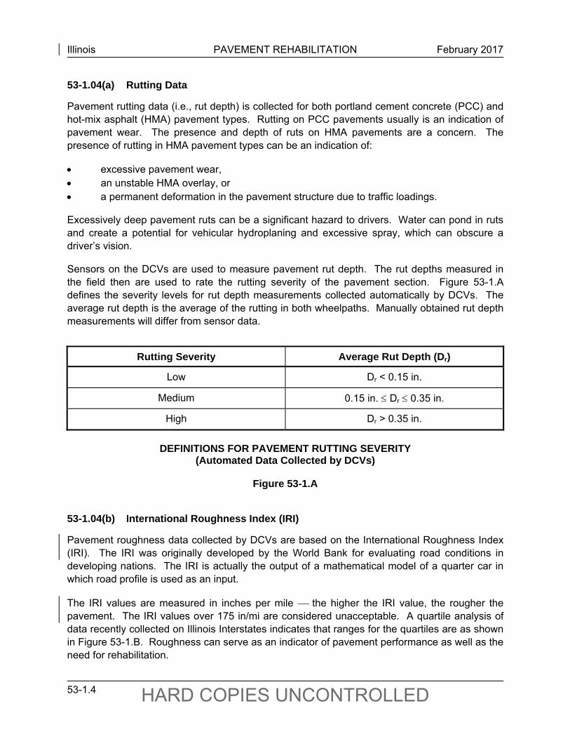
Sensors on the DCVs are used to measure pavement rut depth. The rut depths measured in the field then are used to rate the rutting severity of the pavement section. Figure 53-1.A defines the severity levels for rut depth measurements collected automatically by DCVs. The average rut depth is the average of the rutting in both wheelpaths. Manually obtained rut depth measurements will differ from sensor data.
Rutting Severity Average Rut Depth (Dr)
Low Dr < 0.15 in.
Medium 0.15 in. Dr 0.35 in.
High Dr > 0.35 in.
DEFINITIONS FOR PAVEMENT RUTTING SEVERITY
(Automated Data Collected by DCVs)
Figure 53-1.A
53-1.04(b) International Roughness Index (IRI)
Pavement roughness data collected by DCVs are based on the International Roughness Index (IRI). The IRI was originally developed by the World Bank for evaluating road conditions in developing nations. The IRI is actually the output of a mathematical model of a quarter car in which road profile is used as an input.
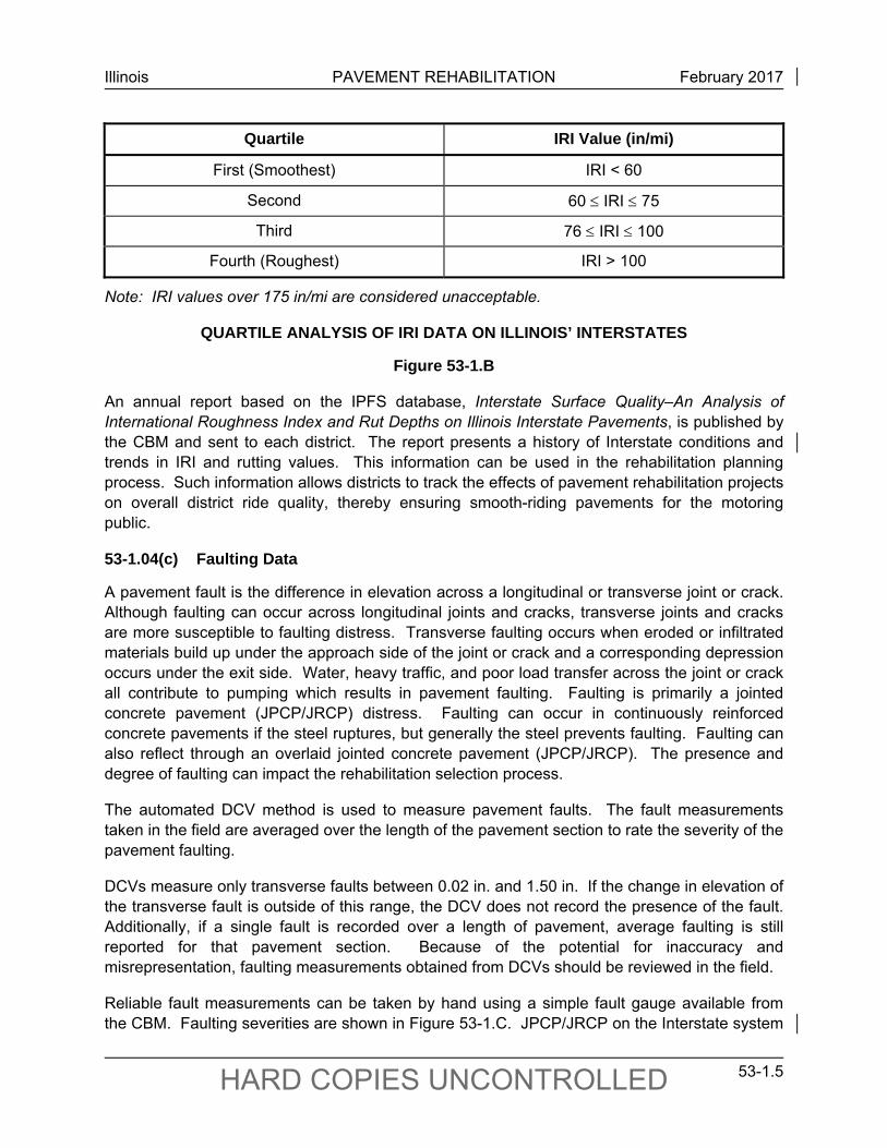
The IRI values are measured in inches per mile the higher the IRI value, the rougher the pavement. The IRI values over 175 in/mi are considered unacceptable. A quartile analysis of data recently collected on Illinois Interstates indicates that ranges for the quartiles are as shown in Figure 53-1.B. Roughness can serve as an indicator of pavement performance as well as the need for rehabilitation.
Illinois PAVEMENT REHABILITATION February 2017
53-1.5 HARD COPIES UNCONTROLLED
Quartile IRI Value (in/mi)
First (Smoothest) IRI < 60
Second 60 IRI 75
Third 76 IRI 100
Fourth (Roughest) IRI > 100
Note: IRI values over 175 in/mi are considered unacceptable.
QUARTILE ANALYSIS OF IRI DATA ON ILLINOIS’ INTERSTATES
Figure 53-1.B
An annual report based on the IPFS database, Interstate Surface Quality–An Analysis of International Roughness Index and Rut Depths on Illinois Interstate Pavements, is published by the CBM and sent to each district. The report presents a history of Interstate conditions and trends in IRI and rutting values. This information can be used in the rehabilitation planning process. Such information allows districts to track the effects of pavement rehabilitation projects on overall district ride quality, thereby ensuring smooth-riding pavements for the motoring public.
53-1.04(c) Faulting Data
A pavement fault is the difference in elevation across a longitudinal or transverse joint or crack. Although faulting can occur across longitudinal joints and cracks, transverse joints and cracks are more susceptible to faulting distress. Transverse faulting occurs when eroded or infiltrated materials build up under the approach side of the joint or crack and a corresponding depression occurs under the exit side. Water, heavy traffic, and poor load transfer across the joint or crack all contribute to pumping which results in pavement faulting. Faulting is primarily a jointed concrete pavement (JPCP/JRCP) distress. Faulting can occur in continuously reinforced concrete pavements if the steel ruptures, but generally the steel prevents faulting. Faulting can also reflect through an overlaid jointed concrete pavement (JPCP/JRCP). The presence and degree of faulting can impact the rehabilitation selection process.
The automated DCV method is used to measure pavement faults. The fault measurements taken in the field are averaged over the length of the pavement section to rate the severity of the pavement faulting.
DCVs measure only transverse faults between 0.02 in. and 1.50 in. If the change in elevation of the transverse fault is outside of this range, the DCV does not record the presence of the fault. Additionally, if a single fault is recorded over a length of pavement, average faulting is still reported for that pavement section. Because of the potential for inaccuracy and misrepresentation, faulting measurements obtained from DCVs should be reviewed in the field.
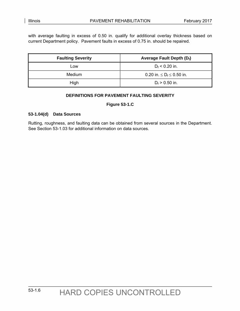
Reliable fault measurements can be taken by hand using a simple fault gauge available from the CBM. Faulting severities are shown in Figure 53-1.C. JPCP/JRCP on the Interstate system
Illinois PAVEMENT REHABILITATION February 2017
53-1.6 HARD COPIES UNCONTROLLED
with average faulting in excess of 0.50 in. qualify for additional overlay thickness based on current Department policy. Pavement faults in excess of 0.75 in. should be repaired.
Faulting Severity Average Fault Depth (Df)
Low Df < 0.20 in.
Medium 0.20 in. Df 0.50 in.
High Df > 0.50 in.
DEFINITIONS FOR PAVEMENT FAULTING SEVERITY
Figure 53-1.C
53-1.04(d) Data Sources
Rutting, roughness, and faulting data can be obtained from several sources in the Department. See Section 53-1.03 for additional information on data sources.
Illinois PAVEMENT REHABILITATION September 2010
53-2.1 HARD COPIES UNCONTROLLED
53-2 PAVEMENT DISTRESS TYPES
Pavement distresses may be indicative of two distinctly different types of failures:
1. Structural Failure. Structural failure is the loss of load carrying capacity of the pavement structure or a breakdown of one or more of the pavement’s structural components or the underlying subgrade of such a magnitude as to make the pavement incapable of sustaining the traffic loads imposed upon its surface.
2. Surface (Functional) Failure. Surface, or functional, failure may or may not be accompanied by structural failure, but it is such that the pavement will not carry out its intended function without causing discomfort to passengers or without causing high stresses in the vehicle that passes over it due to pavement roughness.
It is important to clearly understand the distinction between these two types of failures when identifying and assessing distress types, the cause of failure, and developing rehabilitation strategies. Otherwise, a rehabilitation project may not adequately mitigate the pavement deficiency or may be excessively more costly than necessary. Also, the distress types and severities listed below do not include the distress codes used in the CRS data. These codes may be obtained from OPP.
53-2.01 Diagnosing Structural and Surface Distresses
Identifying and assessing pavement distresses to determine whether or not the pavement is exhibiting a structural or functional failure is paramount. The degree of distress for both structural and surface failures is gradational, and the severity of distress is largely subjective. For example, consider a rigid pavement that has been resurfaced with an HMA overlay. The surface may develop rough spots as a result of breakup in the HMA overlay (i.e., functional failure) without structural breakdown of the underlying rigid structure. Conversely, the same pavement may crack and break up as a result of vehicular overload (i.e., structural failure). Rehabilitation measures for the first situation may consist of resurfacing to restore a smooth-riding surface. However, if the distress represents a structural failure, the entire pavement structure may require major or complete rehabilitation. Selecting the proper rehabilitation method depends on accurate diagnoses of the distress type to obtain a cost-effective rehabilitation. The cause of either of the above example distress conditions may be threefold:
vehicular overload (e.g., excessive gross loads, high repetition of loads, high tire pressures) which can cause either structural or functional failure;
climatic and environmental conditions which can cause surface irregularities and structural weakness (e.g., frost heaving, volume change in soil due to wetting and drying, breakup resulting from freezing and thawing, improper drainage); and
disintegration of paving materials due to freezing and thawing and/or wetting and drying (e.g., “D” cracking, scaling of rigid pavements resulting from nondurable aggregates or ice-removal salts, breakdown of base course materials into fines causing an unstable mix to develop).
Illinois PAVEMENT REHABILITATION September 2010
53-2.2 HARD COPIES UNCONTROLLED
The rehabilitation of pavements in Illinois presents several challenges for the designer. It is essential that the designer be familiar with distress types, causes, and the means for their rehabilitation. While reviewing distresses on a section, the designer must consider the structural integrity of the existing section and select a rehabilitation strategy to address items such as inadequate structure for design traffic, original construction deficiencies, past maintenance, material durability, and geometric limitations.
53-2.02 Hot-Mix Asphalt (HMA) Pavement Distresses
This section applies to both HMA pavements and rigid pavements that have been resurfaced with an HMA overlay. The distresses that may be encountered include the following:
1. Alligator (Fatigue) Cracking. Alligator, or fatigue, cracking is a series of interconnecting cracks forming many-sided, sharp-edged pieces. The cracks develop a pattern resembling chicken wire or the skin of an alligator. The longest side of the pieces is usually less than 1 ft in length. Pattern-type cracking that occurs over an area not subjected to traffic load is rated as block cracking.
a. Severity Levels.
Low. Longitudinal disconnected hairline cracks running parallel to each other. The cracks are not spalled. Initially there may be only a single crack in the wheelpath.
Medium. Further development of low severity fatigue cracking into a pattern of pieces formed by cracks that may be sealed.
High. Medium fatigue cracking has progressed so that pieces are more severely spalled at the edges and may have loosened until the cells rock under traffic. Pumping may exist.
b. Diagnosis. Usually indicates a structural failure in the pavement and can be related to poor subgrade support.
2. Bleeding. Asphalt bleeding, sometimes called flushing, is the presence of excess asphalt binder on the pavement surface. It usually occurs in the wheelpaths. Asphalt material spilled onto the surface from sealing operations or moving vehicles should not be included.
a. Severity Levels. Severity levels are not applicable to this distress type.
b. Diagnosis. By itself, this distress usually indicates a surface failure or material design problem. Excessive areas of bleeding may indicate the presence of stripping in the HMA mixture.
3. Block Cracking. Block cracking, sometimes called area cracking, divides the HMA surface into somewhat rectangular pieces. The blocks can range in size from
Illinois PAVEMENT REHABILITATION September 2010
53-2.3 HARD COPIES UNCONTROLLED
approximately 1 ft2 to 100 ft2. Block cracking normally occurs over a large portion of the pavement area. The cracks usually extend only a short distance into the HMA surface. Block cracking is age and environment related and should not be mistaken for alligator cracking, which is load related.
a. Severity Levels.
Low. Cracks are tight with a mean width 0.25 in. or less. Minor or no spalling is present.
Medium. Crack width is between 0.25 in. and 0.50 in. Cracks may be moderately spalled. Low severity random parallel cracking may exist near the crack or at the intersection of cracks.
High. One or more of the following conditions exist:
crack width is greater than 0.50 in.,
crack is severely spalled, and/or
medium or severe random parallel cracking exists near the crack or at the intersection of the cracks.
b. Diagnosis. By itself, this distress does not usually indicate a structural failure. It is considered a surface failure.
4. Centerline Cracking. Centerline cracking is located along the centerline of the existing surface of two-lane pavements and between lanes of pavements with three or more lanes. The joint formed by the HMA paving operation is included in this distress.
a. Severity Levels.
Low. Cracks are tight with a mean width of 0.25 in. or less. Minor or no spalling present.
Medium. Crack width is between 0.25 in. and 0.50 in. Cracks may be moderately spalled. Low severity random parallel cracking may exist near the crack or at the intersection of cracks.
High. One or more of the following conditions exist:
crack width is greater than 0.50 in.,
crack is severely spalled, and/or
medium or severe random parallel cracking exists near the crack or at the intersection of cracks.
b. Diagnosis. Low severity usually indicates a surface failure. However, a high severity level may indicate a structural failure.
Illinois PAVEMENT REHABILITATION September 2010
53-2.4 HARD COPIES UNCONTROLLED
5. Edge Cracking. Crescent-shaped cracks or fairly continuous cracks that are parallel to and usually within 1 ft to 2 ft of the outer edge of the pavement and are usually load related.
a. Severity Levels.
Low. Cracks with no breakup or raveling.
Medium. Cracks with some breakup or raveling.
High. Cracks with considerable breakup or raveling along the edge.
b. Diagnosis. A low severity usually indicates a surface failure. However, a high severity level may indicate a structural failure.
6. Longitudinal Cracking. Longitudinal cracks are generally parallel to the centerline. They may appear anywhere between the centerline and the outer edge of the outer wheelpath. These cracks may be fairly straight or may meander within the lane width. This distress does not include centerline distress or widening distress.
a. Severity Levels.
Low. Cracks are tight with a mean width of 0.25 in. or less. Minor or no spalling present.
Medium. Crack width is between 0.25 in. to 0.50 in. Cracks may be moderately spalled. Low severity random parallel cracks may exist near the crack or at the intersection of cracks.
High. One or more of the following conditions exist:
crack width is greater than 0.25 in.,
crack is severely spalled, and/or
medium or severe random parallel cracks exist near the crack or at the intersection of cracks.
b. Diagnosis. A low severity level usually indicates a surface failure. However, a high severity level may indicate a structural failure.
7. Permanent Patch Deterioration. A patch is an area where a portion or all of the original pavement slab has been removed and replaced with a permanent type of material (e.g., PCC or HMA). Only permanent patches should be considered.
a. Severity Levels.
Low. Any patch that is present. The patch has little or no deterioration. Cracks and edge joints are tight. Low severity distress may exist. No faulting or settlement has occurred. Patch is rated low severity even if it is in excellent condition.
Illinois PAVEMENT REHABILITATION September 2010
53-2.5 HARD COPIES UNCONTROLLED
Medium. Patch is somewhat deteriorated. Settlement is less than 0.50 in. Cracking, rutting, or shoving has occurred in an HMA patch. Concrete patch may exhibit spalling and/or faulting up to 0.50 in. around the edges and/or cracks.
High. Patch is badly deteriorated either by cracking, faulting, spalling, rutting, humping, or shoving to a condition which requires replacement. Patch may present tire damage potential.
b. Diagnosis. All severity levels may indicate a surface failure or an impending localized structural failure.
8. Potholes and Localized Distress. Potholes and localized distress are bowl-shaped holes of various sizes in the pavement surface. The HMA material has broken into small pieces by fatigue cracking or by localized disintegration of the mixture and the material is removed by traffic. Base failures, poor drainage, and weak or thin HMA layers can contribute to the formation of potholes. This distress does not include reflective “D” cracking as identified by white fines or stains on the surface. Potholes or localized failures associated with cracks or joints are not recorded under this distress.
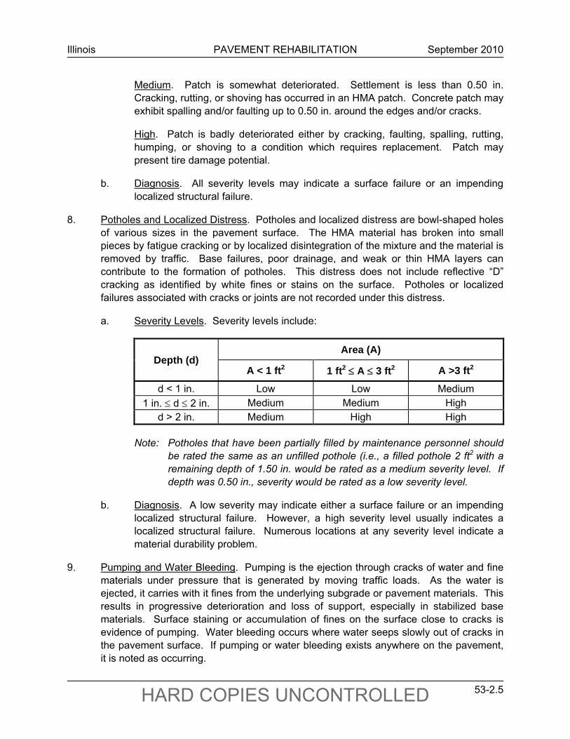
a. Severity Levels. Severity levels include:
Depth (d) Area (A)
A < 1 ft2 1 ft2 A 3 ft2 A >3 ft2
d < 1 in. Low Low Medium
1 in. d 2 in. Medium Medium High d > 2 in. Medium High High
Note: Potholes that have been partially filled by maintenance personnel should
be rated the same as an unfilled pothole (i.e., a filled pothole 2 ft2 with a remaining depth of 1.50 in. would be rated as a medium severity level. If depth was 0.50 in., severity would be rated as a low severity level.
b. Diagnosis. A low severity may indicate either a surface failure or an impending localized structural failure. However, a high severity level usually indicates a localized structural failure. Numerous locations at any severity level indicate a material durability problem.
9. Pumping and Water Bleeding. Pumping is the ejection through cracks of water and fine materials under pressure that is generated by moving traffic loads. As the water is ejected, it carries with it fines from the underlying subgrade or pavement materials. This results in progressive deterioration and loss of support, especially in stabilized base materials. Surface staining or accumulation of fines on the surface close to cracks is evidence of pumping. Water bleeding occurs where water seeps slowly out of cracks in the pavement surface. If pumping or water bleeding exists anywhere on the pavement, it is noted as occurring.
Illinois PAVEMENT REHABILITATION September 2010
53-2.6 HARD COPIES UNCONTROLLED
a. Severity Levels.
Low. Water bleeding exists or water pumping can be observed when heavy vehicular loads pass over the pavement surface. However, no fines can be seen on the surface of the pavement.
Medium. A small amount of pumped material can be observed near cracks in the surface.
High. A significant amount of pumped material exists on the surface near the cracks.
b. Diagnosis. Water bleeding alone may indicate either a surface failure or an impending structural failure. Any level of pumping usually indicates a structural failure.
10. Raveling, Weathering, and Segregation. This distress group is the wearing away of the pavement surface caused by the dislodging of aggregate particles (raveling) and loss of asphalt binder (weathering). Segregation is the result of the coarse and fine components of the HMA mix being unintentionally segregated during construction.
a. Severity Levels.
Low. Wearing away of the aggregate or binder has begun but has not progressed significantly.
Medium. Aggregate and/or binder has worn away. Surface texture is becoming rough and pitted. Loose particles generally exist.
High. Aggregate and/or binder has worn away. Surface texture is very rough and pitted.
b. Diagnosis. By itself, this distress usually indicates a surface failure. However, this distress group is often the starting point for subsequent localized structural failure.
11. Reflective “D” Cracking. Series of interconnecting cracks in the wheelpath or at the outside edge of overlaid “D”-cracked concrete pavement. The surface has an alligator cracking pattern with the seeping of water and fine material from the underlying concrete. Typically, the area is depressed and tends to be found as a localized area of distress.
a. Severity Levels.
Low. Interconnecting cracks in small area (12 in. diameter or less) with little or no fines evident.
Illinois PAVEMENT REHABILITATION September 2010
53-2.7 HARD COPIES UNCONTROLLED
Medium. Area of interconnecting cracks in an area of 12 in. diameter or greater. Any area with a moderate amount of fines evident. Area may be depressed.
High. Any area with severe interconnecting cracking and loss of surface material or evidence of patching. Maintenance patching has been performed or is needed.
b. Diagnosis. Usually indicates a localized structural failure in the pavement.
12. Reflective Widening Cracking. Reflective widening cracking runs parallel to the pavement edge. This type of crack typically occurs 2 ft to 4 ft from the edge of both sides of the pavement and is very straight. In some cases, the crack may occur 6 ft to 8 ft from one edge of the pavement, indicating all of the widening was placed on one side.
a. Severity Levels.
Low. Cracks are tight with a mean width of 0.25 in. or less. Minor or no spalling present.
Medium. Crack width is between 0.25 in. and 0.50 in. Cracks may be moderately spalled. Low severity random parallel cracking may exist near the crack or at the intersection of cracks.
High. One or more of the following conditions exist:
crack width is greater than 0.50 in.,
crack is severely spalled, and/or
medium or severe random parallel cracking exists near the crack or at the intersection of cracks.
b. Diagnosis. A low severity usually indicates a surface failure. However, a high severity level may indicate a structural failure.
13. Rutting. A rut is a surface depression in the wheelpath. Pavement uplift may occur along the sides of the rut. Rutting may be a materials related problem or may be a result of traffic loading.
a. Severity Levels (Based on DCV Sensor Data).
Low. Ruts average less than 0.15 in. deep.
Medium. Ruts average 0.15 in. to 0.35 in. deep.
High. Ruts average more than 0.35 in. deep.
b. Diagnosis. A low severity may indicate either a surface failure or an impending structural failure. However, a high severity level usually indicates a structural failure of the HMA mixture.
Illinois PAVEMENT REHABILITATION September 2010
53-2.8 HARD COPIES UNCONTROLLED
14. Shoving. Shoving is a longitudinal displacement of a localized area of the HMA surface. Shoving is generally caused by braking or accelerating vehicles at locations on hills, curves, and intersections. It also may have associated vertical displacement. Shoving is a form of plastic movement of the HMA mixture.
a. Severity Levels. Severity levels are not applicable to this distress type.
b. Diagnosis. By itself, this distress usually indicates a surface failure. However, excessive displacement that is continuous usually indicates a structural failure of the HMA mixture.
15. Transverse Cracking. Transverse cracks extend across the pavement more or less perpendicular to the centerline. These cracks are caused by the underlying pavement or stabilized base reflecting through the HMA surface. The cracks also may be due to thermal cracking of the HMA surface.
a. Severity Levels.
Low. Cracks are tight with a mean width of 0.25 in. or less. Minor or no spalling present.
Medium. Crack width is between 0.25 in. and 0.50 in. Cracks may be moderately spalled. Low severity random parallel cracking may exist near the crack or at the intersection of cracks.
High. The crack area may be depressed causing severe bump to a vehicle and/or one or more of the following conditions exist:
crack width is greater than 0.50 in.,
crack is severely spalled, and/or
medium or severe random parallel cracking exists near the crack or at the intersection of cracks.
b. Diagnosis. A low severity may indicate either a surface failure or an impending structural failure. However, a high severity level usually indicates extreme vertical movements or a structural failure.
53-2.03 Jointed Plain/Reinforced Concrete Pavement Distresses
The distresses that may be encountered on Jointed Plain Concrete Pavement (JPCP) and Jointed Reinforced Concrete Pavement (JRCP) include the following:
1. Blowups. Most blowups occur during spring and hot summer at transverse joints or wide cracks. Rain or wet pavement just prior to a hot period is closely related to blowups.
Illinois PAVEMENT REHABILITATION September 2010
53-2.9 HARD COPIES UNCONTROLLED
Infiltration of incompressible materials into joints or cracks during cold periods results in high compressive stresses during hot periods. Where this compressive pressure becomes too great, a localized upward movement or shattering of the slab occurs at the joint or crack. Blowups are accelerated due to spalling of material from the slab bottom which creates a reduced joint contact area. The presence of “D” cracking or freeze-thaw damage weakens the concrete near the joint which further increases spalling and blowup potential.
a. Severity Levels.
Low. Blowup has occurred, but only causes some bounce of the vehicle, which creates no discomfort.
Medium. Blowup causes a significant bounce of the vehicle, which creates some discomfort. Temporary patching may have been placed because of the blowup.
High. Blowup causes excessive bounce of the vehicle which creates substantial discomfort, and/or a safety hazard, and/or vehicle damage requiring a reduction in speed for safety. High severity blowups require immediate maintenance due to the safety hazard.
b. Diagnosis. All severity levels indicate an impending structural failure.
2. Corner Breaks. A corner break is a crack that intersects the joints at a distance less than 6 ft on each side measured from the corner of the slab. A corner break extends vertically through the entire slab thickness. Load repetition combined with loss of support, poor load transfer across joint, and thermal curling and moisture warping stresses usually cause corner breaks.
a. Severity Levels.
Low. Crack is tight (hairline). Well-sealed cracks will be considered tight. No faulting or break-up at broken corner exists. Crack is not spalled.
Medium. Crack is working and spalled at low or medium severity. Break-up of broken corner has not occurred. Faulting of crack or joint is less than 0.50 in. Temporary patching may have been placed because of corner break.
High. Crack is spalled at high severity or the corner piece has broken into two or more pieces. If faulting of crack or joint is more than 0.50 in., it will be considered high severity.
b. Diagnosis. A low severity indicates an impending structural failure. However, a high severity level usually indicates a structural failure.
3. “D” Cracking. “D” cracking is a series of closely spaced hairline cracks that usually begins on the PCC pavement slab surface adjacent to transverse and longitudinal joints and cracks and at the free edge of JPCP and JRCP. The surface cracks often appear
Illinois PAVEMENT REHABILITATION September 2010
53-2.10 HARD COPIES UNCONTROLLED
as a darker stained area and may contain a white residue, which leaches from the cracks. Staining alone does not indicate the presence of “D” cracking. “D” cracking is the expansion of susceptible coarse aggregate by the wetting, drying, freezing, and thawing cycles imposed by the Illinois climate.
a. Severity Levels.
Low. The characteristic crack pattern is evident along with staining and leaching. A fan shape spreading of the cracks is also evident. No spalling is present.
Medium. The characteristic crack pattern is very evident and patterns at individual transverse cracks are beginning to join together. Minor spalling is evident and the pavement may produce a hollow sound when thumped. Little or no maintenance patching exists.
High. A high level of spalling is evident and the pavement may produce a hollow sound when thumped. Patching has been performed or is necessary. Considerable loose material exists along the shoulders. A crack pattern is formed between several adjacent transverse cracks.
b. Diagnosis. Indicates a material durability problem and usually indicates a structural failure in the pavement.
4. High Steel Spalling. This distress is the spalling of the concrete surface that results from the placement during construction of the reinforcing steel too high in the cross section of the pavement (i.e., too near to the surface). Usually, the reinforcing steel itself is visible and localized surface distress exists (i.e., an area of slab surface where the concrete has broken into pieces and spalled).
a. Severity Levels.
Low. Spalling is less than 12 in. in diameter or length.
Medium. Spalling is 12 in. to 18 in. in diameter or length.
High. Spalling is over 18 in. in diameter or length.
b. Diagnosis. By itself, this distress usually indicates a surface failure. However, high severity levels, left unattended, may result in a reduced cross section and rupture of reinforcing steel, which may cause localized structural failures.
5. Joint/Crack Faulting. Faulting is the difference in elevation across a joint or crack. Faulting is caused in part by the buildup of loose materials under the approach side of the joint or crack as well as a depression under the exit side. The buildup of eroded or infiltrated materials is caused by pumping from under the exit slab and shoulder (free moisture under pressure) due to heavy traffic loadings. The warp and/or curl upward of the slab near the joint due to moisture and/or temperature gradient contributes to the pumping condition. Lack of load transfer contributes greatly to faulting.
Illinois PAVEMENT REHABILITATION September 2010
53-2.11 HARD COPIES UNCONTROLLED
a. Severity Levels. Based on DCV sensor data.
Low. Average faulting is 0.2 in. or less.
Medium. Average faulting is between 0.2 in. and 0.50 in.
High. Average faulting is greater than 0.50 in.
b. Diagnosis. Any severity level indicates an impending structural failure.
6. Joint/Crack Spalling. Cracking, breaking, chipping, or spalling of slab edges within 2 ft of transverse joints or cracks.
a. Severity Levels.
Low. Spalls less than 3 in. wide, measured to the center of the joint/crack, with loss of material, or spalls with no loss of material and no patching.
Medium. Spalls 3 in. to 6 in. wide, measured to the center of the joint/crack, with loss of material.
High. Spalls greater than 6 in. wide, measured to the center of the joint/crack, with loss of material.
b. Diagnosis. By itself, indicates high compressive forces or incompressible material in joint/crack. At high levels, this distress usually indicates a surface failure.
7. Joint Deterioration. Joint deterioration is the cracking, widening, or faulting of the concrete at a joint.
a. Severity Levels.
Low. Tight hairline cracking around joints with no spalling or faulting.
Medium. The joint has opened to a width less than 1 in. or has 0.25 in. faulting or spalling. The area between the crack and joint has begun to break up but is not dislodged.
High. The joint has opened to a width of greater than 1 in. or has a high level (0.50 in.) of faulting or spalling. The area between the crack and the joint has broken up and pieces are dislodged to the point that tire damage may occur.
b. Diagnosis. A low severity may indicate either a surface failure or an impending structural failure. However, a high severity level usually indicates a structural failure.
8. Longitudinal Cracking. Longitudinal cracks generally occur parallel to the centerline of the pavement but may meander throughout the lane. This does not include centerline distress. They may be the result of concrete shrinkage, warping stresses, improper sawing, or loss of support.
Illinois PAVEMENT REHABILITATION September 2010
53-2.12 HARD COPIES UNCONTROLLED
a. Severity Levels.
Low. Tight hairline crack with no spalling or faulting or a well sealed crack with no visible faulting or spalling. Does not include “Y” or interconnecting cracks.
Medium. Working crack with a moderate or low severity of spalling and/or faulting less than 0.50 in. Includes “Y” and interconnecting cracks with no punchouts or material loss.
High. A crack which exhibits one or more of the following:
width greater than 1 in., high severity level or spalling, and/or faulting of 0.50 in. or more.
High severity includes “Y” and interconnecting cracks with punchouts or material loss. Maintenance patching is present or is needed.
b. Diagnosis. A low severity may indicate an impending structural failure. However, a high severity level usually indicates a structural failure.
9. Map Cracking and Scaling. Map cracking, or crazing, is a network of shallow hairline cracks which extend only through the upper surface of the concrete. It is usually caused by over-finishing the concrete surface. Care must be taken to avoid confusing this distress with “D” cracking. Map cracking usually does not exhibit the staining or leaching associated with “D” cracking nor is a hollow sound produced by thumping the pavement. Scaling is the removal of the thin top surface of the concrete usually associated with map cracking.
a. Severity Levels. Severity levels are not applicable to this distress type.
b. Diagnosis. By itself, this distress usually indicates a surface failure.
10. Permanent Patch Deterioration. A patch is an area where a portion or all of the original concrete slab has been removed and replaced with a permanent type of material (e.g., PCC or HMA). Only permanent patches should be considered. Deterioration of the original concrete slab adjacent to the permanent patch is termed patch adjacent slab deterioration. This may be in the form of spalling of the slab/patch joint, “D” cracking of the slab adjacent to the patch, or a corner break in the adjacent slab. Distress which begins more than 6 ft from the patch is not included in patch adjacent slab deterioration.
a. Severity Levels.
Low. Any patch that is present. Patch has little or no deterioration. Cracks and edge joints are tight. Low severity spalling or raveling may exist. No faulting or settlement has occurred. Patch is rated low severity even if in excellent condition.
Illinois PAVEMENT REHABILITATION September 2010
53-2.13 HARD COPIES UNCONTROLLED
Medium. Patch is somewhat deteriorated. Settlement is less than 0.50 in. Cracking, rutting, or shoving has occurred in an HMA patch. Concrete patch may exhibit spalling and/or faulting up to 0.50 in. around the edges of cracks.
High. Patch is badly deteriorated either by cracking, faulting, spalling, rutting, or shoving to a condition that requires replacement. Patch may present tire damage potential.
b. Diagnosis. A low severity usually indicates a surface failure. However, a high severity level may be either a progressively deteriorated surface condition or an impending localized structural failure.
11. Polished Aggregate. This distress is the wearing away of the surface texture such that a loss of skid resistance can result.
a. Severity Levels. Severity levels are not applicable to this distress type.
b. Diagnosis. By itself, this distress usually indicates a surface failure.
12. Pumping and Water Bleeding. Pumping is the ejection of material by water through joints or cracks, caused by deflection of the slab under moving traffic loads. As the water is ejected, it carries with it particles of gravel, sand, clay, or silt resulting in a progressive loss of pavement support. Surface staining or accumulation of base or subgrade material on the pavement surface close to joints or cracks is evidence of pumping. However, pumping can occur without such evidence, particularly where stabilized bases are used. The observation of water being ejected by heavy traffic loads after a rainstorm can also be used to identify pumping. Water bleeding occurs where water seeps out of joints or cracks.
a. Severity Levels.
Low. Water is forced out of a joint or crack when trucks pass over the joints or cracks; water is forced out of the lane/shoulder joint when trucks pass along the joint; or water bleeding exists. No fines can be seen on the surface of the traffic lanes or shoulder.
Medium. A small amount of pumped material can be observed near some of the joints or cracks on the surface of the traffic lane or shoulder.
High. A significant amount of pumped materials exist on the pavement surface of the traffic lane or shoulder along the joints or cracks.
b. Diagnosis. Water bleeding alone may indicate either a surface failure or an impending structural failure. Any level of pumping usually indicates a structural failure.
13. Transverse Cracking. Transverse cracking of JPCP or JRCP slabs is a normal occurrence and is caused by one or more of the following:
Illinois PAVEMENT REHABILITATION September 2010
53-2.14 HARD COPIES UNCONTROLLED
heavy vehicular load repetition, thermal and moisture gradient stresses, drying shrinkage stresses, loss of subgrade support, and/or non-functioning contraction joints.
a. Severity Levels.
Low. Tight hairline cracks with no spalling or faulting or a well sealed crack with no visible faulting or spalling.
Medium. Working crack with low to medium severity level of spalling and/or faulting less than 0.50 in. Temporary patching may be present.
High. A crack that exhibits one or more of the following:
width greater than 1 in., high severity level of spalling, and/or faulting of 0.50 in. or more.
b. Diagnosis. A low severity may indicate either a surface failure or an impending structural failure. However, a high severity level usually indicates a structural failure.
14. Transverse Joint Seal Damage. The following applies to JPCP or JRCP constructed prior to 2003. Existing preformed joint seals should be evaluated as they do not meet current design dimensions and do require sealing to perform. Joint seal damage is any condition that enables incompressible materials to infiltrate into the joints from the surface or allows significant infiltration of water. Accumulation of incompressible materials within the joints restricts in-slab expansion and may result in the slab buckling, shattering, or spalling. A pliable joint filler that is bonded to the edges of the slabs protects the joints from accumulation of incompressible materials and also reduces the amount of water seeping into the pavement structure. Transverse joint seal damage is rated based on the overall condition of the sealant over the entire pavement section. Typical types of joint seal damage are:
stripping of joint sealant, extrusion of joint sealant, weed growth, hardening of the filler (oxidation), loss of bond to the slab edges, and lack or absence of sealant in the joint.
a. Severity Levels.
Low. Joint sealer is in generally good condition throughout the section. Sealant is performing well with only a minor amount of any of the above types of damage
Illinois PAVEMENT REHABILITATION September 2010
53-2.15 HARD COPIES UNCONTROLLED
present. Little water and no incompressible materials can infiltrate through the joint.
Medium. Joint sealer is in generally fair condition over the entire section with one or more of the above types of damage occurring to a moderate degree. Water can infiltrate the joint fairly easily; some incompressible materials can infiltrate the joint. Sealant needs replacement within 3 years.
High. Joint sealer is in generally poor condition over the entire section with one or more of the above types of damage occurring to a severe degree. Water and incompressible materials can freely infiltrate the joint. Sealant needs immediate replacement.
b. Diagnosis. By itself, this distress usually indicates a failure of the joint material. Prolonged inattention to the problem can lead to surface or even structural failures.
53-2.04 Continuously Reinforced Concrete (CRC) Pavement Distresses
The distresses that may be encountered on continuously reinforced concrete pavements include the following:
1. Blowups. Blowups are caused by a combination of thermal and moisture expansive forces that exceed the pavement system’s ability to absorb in conjunction with a pavement discontinuity. Blowups occur at construction joints or at wide transverse cracks at which the steel has previously ruptured. The result is a localized upward movement (buckling) of the slab at the edges of the crack or construction joint accompanied by shattering of the concrete or crushing of the slab in that area. Rain or wet pavement just prior to a hot period is closely related to blowups.
a. Severity Levels.
Low. Buckling or shattering has occurred, but only causes some bounce of the vehicle which creates no discomfort.
Medium. Buckling or shattering causes a significant bounce of the vehicle which creates some discomfort. Temporary patching has been placed because of a blowup.
High. Buckling or shattering causes excessive bounce of the vehicle which creates substantial discomfort, and/or a safety hazard, and/or vehicle damage, requiring a reduction in speed for safety. High severity blowups require immediate maintenance due to the safety hazard.
b. Diagnosis. All severity levels may indicate an impending structural failure.
Illinois PAVEMENT REHABILITATION September 2010
53-2.16 HARD COPIES UNCONTROLLED
2. Centerline Joint Spalling. Cracking, breaking, chipping, or fraying of slab edges within 2 ft of the centerline (lane-to-lane) joint.
a. Severity Levels.
Low. Spalls less than 3 in. wide, measured to the center of the joint, with loss of material, or spalls with no loss of material and no patching.
Medium. Spalls 3 in. to 6 in. wide, measured to the center of the joint, with loss of material.
High. Spalls greater than 6 in. wide, measured to the center of the joint, with loss of material.
b. Diagnosis. By itself, this distress usually indicates a surface failure.
3. Closed Expansion Joints. Existing CRCP expansion joints which have become closed can result in other failures such as spalling, cracking, or blowups in the pavement.
a. Severity Levels. Severity levels are not applicable to this distress type.
b. Diagnosis. If other distresses are allowed to occur and increase in severity, structural integrity of the pavement may be compromised.
4. Construction Joint Deterioration. Construction joint distress is a breakdown of the concrete or steel at a CRCP construction joint. It often results in a series of closely spaced transverse cracks near the construction joint or a large number of interconnecting cracks. These excessive cracks can, in time, lead to spalling and breakup of the concrete. If an inadequate steel lap or a steel rupture occurs at a construction joint, the result is often spalling and disintegration of the surrounding concrete, and a possible punchout. This can also lead to a readily accessible entrance for water. The primary causes of construction joint distress are poorly consolidated concrete and inadequate steel content or placement.
a. Severity Levels.
Low. Only closely spaced tight cracks with no spalling or faulting occur within 10 ft of each side of the construction joint.
Medium. Some low severity spalling of cracks, or a low severity punchout exists within 10 ft of either side of the construction joint. Temporary patching has been placed.
High. Significant deterioration and breakup exists within 10 ft of the construction joint that requires patching.
b. Diagnosis. A low severity may indicate either a surface failure or an impending structural failure. However, a high severity level usually indicates a structural failure.
Illinois PAVEMENT REHABILITATION September 2010
53-2.17 HARD COPIES UNCONTROLLED
5. “D” Cracking. “D” cracking is a series of closely spaced hairline cracks that usually begins on the CRCP surface adjacent to transverse construction joints, longitudinal joints/cracks, the normal tight transverse cracking pattern, and pavement edge. The surface cracks often appear as a darker stained area and may contain a white residue that leaches from the cracks. Staining alone does not indicate the presence of “D” cracking. “D” cracking is the expansion of susceptible coarse aggregate caused by the wetting, drying, freezing, and thawing cycles imposed by the Illinois climate.
a. Severity Levels.
Low. The characteristic crack pattern is evident along with staining and leaching. A fan shape spreading of the cracks is also evident. No spalling is present.
Medium. The characteristic crack pattern is very evident and patterns at individual transverse cracks are beginning to join together. Minor spalling is evident and the pavement may produce a hollow sound when thumped. Little or no maintenance patching exists.
High. A high level of spalling is evident and the pavement may produce a hollow sound when thumped. Patching has been performed or is necessary. Considerable loose material exists along the shoulders. A crack pattern is formed between several adjacent transverse cracks.
b. Diagnosis. Indicates a materials durability problem and usually indicates a structural failure in the pavement.
6. High Steel Spalling. This distress is the spalling of the concrete surface that results from the placement during construction of the reinforcing steel too high in the cross section of the pavement (i.e., too near to the surface). Usually, the reinforcing steel itself is visible and localized surface distress exists (i.e., an area of slab surface where the concrete has broken into pieces and spalled).
a. Severity Levels.
Low. Spalling is less than 12 in. in diameter or length.
Medium. Spalling is 12 in. to 18 in. in diameter or length.
High. Spalling is over 18 in. in diameter or length.
b. Diagnosis. By itself, this distress usually indicates a surface failure. However, high severity levels, left unattended, may result in a reduced cross section and rupture of reinforcing steel which will cause a localized structural failure.
7. Longitudinal Cracking. Longitudinal cracks generally occur parallel to the centerline of the pavement but may meander throughout the lane. This distress type does not include centerline distress.
Illinois PAVEMENT REHABILITATION September 2010
53-2.18 HARD COPIES UNCONTROLLED
a. Severity Levels.
Low. Tight hairline crack with no spalling or faulting, or a well sealed crack with no visible faulting or spalling. Does not include “Y” or interconnecting cracks.
Medium. Working crack with a moderate or low severity of spalling and/or faulting less than 0.50 in. Includes “Y” and interconnecting cracks with no punchouts or material loss.
High. A crack which exhibits one or more of the following:
width greater than 1 in., a high severity level of spalling, and/or faulting of 0.50 in. or more.
High severity includes “Y” and interconnecting cracks with punchouts or material loss. Maintenance patching may be present or is needed.
b. Diagnosis. A low severity may indicate an impending structural failure. However, a high severity level usually indicates a structural failure.
8. Map Cracking and Scaling. Map cracking, or crazing, is a network of shallow hairline cracks which extend only through the upper surface of the concrete. It is usually caused by over-finishing the concrete surface. Care must be taken to avoid confusing this distress with “D” cracking. Map cracking usually does not exhibit the staining or leaching associated with “D” cracking nor is the hollow sound produced by thumping the pavement. Scaling is the removal of the thin top surface of the concrete usually associated with map cracking.
a. Severity Levels. Severity levels are not applicable to this distress type.
b. Diagnosis. By itself, this distress usually indicates a surface failure.
9. Permanent Patch Deterioration. A patch is an area where a portion or all of the original concrete slab has been removed and replaced with a permanent type of material (e.g., PCC, HMA). Only permanent patches should be considered. Deterioration of the original concrete slab adjacent to the permanent patch is termed patch adjacent slab deterioration. This may be in the form of spalling of the slab/patch joint or “D” cracking of the slab adjacent to the patch. Distress which begins more than 6 ft from the patch is not included in patch adjacent slab deterioration.
a. Severity Levels.
Low. Any patch that is present. Patch has little or no deterioration. Cracks and edge joints are tight. Low severity spalling or raveling may exist. No faulting or settlement has occurred. Patch is rated low severity even if in excellent condition.
Illinois PAVEMENT REHABILITATION September 2010
53-2.19 HARD COPIES UNCONTROLLED
Medium. Patch is somewhat deteriorated. Settlement is less than 0.50 in. Cracking, rutting, or shoving has occurred in an HMA patch. Concrete patch may exhibit spalling and/or faulting up to 0.50 in. around the edges of cracks.
High. Patch is badly deteriorated either by cracking, faulting, spalling, rutting, or shoving to a condition that requires replacement. Patch may present tire damage potential.
b. Diagnosis. A medium severity usually indicates a surface failure. However, a high severity level may be either a progressively deteriorated surface condition or an impending localized structural failure.
10. Polished Aggregate. This distress is the wearing away of the surface texture such that a loss of skid resistance can result.
a. Severity Levels. Severity levels are not applicable to this distress type.
b. Diagnosis. By itself, this distress usually indicates a surface failure.
11. Pumping and Water Bleeding. Pumping is the ejection of material by water through joints or cracks, caused by deflection of the slab under moving traffic loads. As the water is ejected, it carries with it particles of gravel, sand, clay, or silt resulting in a progressive loss of pavement support. Surface staining or accumulation of base or subgrade material on the pavement surface close to joints or cracks is evidence of pumping. However, pumping can occur without such evidence, particularly where stabilized bases are used. The observation of water being ejected by heavy traffic loads after a rainstorm can also be used to identify pumping. Water bleeding occurs where water seeps out of joints or cracks.
a. Severity Levels.
Low. Water is forced out of a joint or crack when trucks pass over the joints or cracks; water is forced out of the lane/shoulder joint when trucks pass along the joint; or water bleeding exists. No fines can be seen on the surface of the traffic lanes or shoulder. There is evidence of the lane/shoulder joint being worn away be high pressure water.
Medium. A small amount of pumped material can be observed near some of the joints or cracks on the surface of the traffic lane or shoulder.
High. A significant amount of pumped materials exist on the pavement surface of the traffic lane or shoulder along the joints or cracks.
b. Diagnosis. Water bleeding alone may indicate either a surface failure or an impending structural failure. Any level of pumping usually indicates a structural failure.
Illinois PAVEMENT REHABILITATION September 2010
53-2.20 HARD COPIES UNCONTROLLED
12. Punchouts. Punchouts are the primary structural failure mode for CRC pavements. This distress is the area enclosed by two closely spaced transverse cracks, and a short longitudinal crack, typically at the edge of the pavement, but can occur elsewhere in the pavement. As cracks deteriorate, aggregate interlock is lost, leading to steel rupture which allows the concrete within these cracks to be punched downward under load. Localized area of the slab has broken or spalled.
a. Severity Levels.
Low. Longitudinal and transverse cracks are fairly tight. Low severity spalling or faulting less than 0.25 in. exists.
Medium. Moderate spalling or faulting 0.25 in. to 0.50 in. exists. Cracks interconnect.
High. Concrete within the area is punched down by more than 0.50 in.; and/or severely spalled or broken. Temporary patching is present or is required.
b. Diagnosis. Usually indicates a structural failure in the pavement.
13. Transverse Cracking. Transverse cracking of CRC pavements is a normal occurrence and is not in itself considered to be a distress. The purpose of the steel reinforcement is to hold the randomly spaced transverse cracks tightly together. However, if the steel ruptures or shears, load transfer across the crack is lost and the crack becomes a potential location for major distress. Crack spalling or faulting are an indication of sheared reinforcing bars. Some cracks may have widened substantially after steel rupture. Note that transverse cracks sometimes run diagonally across the pavement and intersect (“Y” cracks).
a. Severity Levels.
Low. Tight hairline cracks with no faulting, steel rupture, or spalling.
Medium. The crack is open less than 0.50 in. with no steel rupture, faulting is 0.2 in. or less, and/or there is low severity spalling.
High. A crack with steel rupture, medium to high severity spalling, or crack width greater than 0.50 in.
b. Diagnosis. A medium severity may indicate either a surface failure or an impending structural failure. However, a high severity level usually indicates a structural failure.
14. Wide Flange Beam Terminal Joint Distress. Wide flange beam terminal joint distress may prevent the joint from working properly both at the beam and at the expansion joint between the beam and the bridge approach. The flange of the beam may show signs of fatigue cracking.
Illinois PAVEMENT REHABILITATION September 2010
53-2.21 HARD COPIES UNCONTROLLED
a. Severity Levels. Severity levels are not applicable to this distress type.
b. Diagnosis. Structural integrity is being lost if the pavement area near these joints or if the beam itself show signs of distress and special patching may be required. Contact the BDE for assistance in determining a remedial treatment.
53-2.05 Shoulder Distresses
Shoulder distresses typically encountered on highway facilities include the following:
1. Alligator (Fatigue) Cracking. Cracking of the shoulder surface caused by repeated traffic loadings. The individual pieces of material are usually less than 1 ft on the longest side.
a. Severity Levels.
Low. Longitudinal tight cracks running parallel to each other. The cracks are not spalled.
Medium. The cracks are interconnected in the classic pattern with some spalling and a few loose pieces.
High. The cracks are interconnected forming small pieces which are easily removed. Evidence of base failures are evident and accompanied by rutting.
b. Diagnosis. Usually indicates a structural failure.
2. Block Cracking. Block cracks divide the shoulder surface into approximately rectangular pieces with the blocks ranging in size from 1 ft2 to 100 ft2.
a. Severity Levels.
Low. The blocks are outlined by tight cracks 0.25 in. or less in width with little or no spalling.
Medium. The blocks are outlined by cracks greater than 0.25 in. in width with moderate spalling.
High. Blocks are outlined by severely spalled cracks and base failures are evident.
b. Diagnosis. By itself, this distress does not usually indicate a structural failure. It is considered a surface failure.
3. Bridge Approach Pavement/Shoulder Settlement. Existing bridge approaches that were not initially constructed to current IDOT standards frequently exhibit settlement (i.e., a drop in elevation of the approach pavement and/or shoulder surface below the surface of the bridge deck). The cause of this distress usually is the settlement of the backfill material due to voids that exist beneath the bridge approach pavement and/or shoulder.
Illinois PAVEMENT REHABILITATION September 2010
53-2.22 HARD COPIES UNCONTROLLED
a. Severity Levels.
Low. Settlement is less than 2 in. Drainage is not a problem. Voids are not found beneath the bridge approach. The area is no longer continuing to settle.
Medium. Settlement is approximately 2 in. and/or drainage is a concern. Voids are found beneath the bridge approach and the approach area is likely to continue to settle.
High. Settlement is more than 2 in. and/or drainage is a significant problem. Voids are found beneath the bridge approach and the approach area is likely to continue to settle.
b. Diagnosis. Usually indicates a loss of subgrade support.
4. Lane/Shoulder Dropoff. Lane-to-shoulder dropoff occurs wherever there is a difference in elevation between the traffic lane and shoulder. Typically, the outside shoulder settles due to consolidation or settlement of the underlying granular or subgrade material, or pumping of the underlying material. Shoulder heave may occur due to frost action or swelling soils. Granular or soil shoulder dropoff generally is caused from the removal of shoulder material from passing trucks (i.e., wind action).
a. Severity Levels.
Low. There exists between 0.50 in. to 1 in. difference in elevation between the traffic lane and adjacent shoulder.
Medium. There exists between 1 in. to 2 in. difference in elevation between the traffic lane and adjacent shoulder.
High. There exists greater than a 2 in. difference in elevation between the traffic lane and adjacent shoulder.
b. Diagnosis. Usually indicates differential subgrade support between the lane and shoulder.
5. Lane/Shoulder Joint Deterioration. Cracking, breaking, chipping, spalling, or raveling of lane/shoulder joint.
a. Severity Levels.
Low. Cracking and/or spalling less than 3 in. wide.
Medium. Cracking and/or spalling 3 in. to 6 in. wide.
High. Cracking and/or spalling greater than 6 in. wide.
b. Diagnosis. By itself, this distress usually indicates a surface failure.
Illinois PAVEMENT REHABILITATION September 2010
53-2.23 HARD COPIES UNCONTROLLED
6. Lane/Shoulder Separation. Lane-to-shoulder joint separation is the widening of the joint between the edge of the pavement and the shoulder. As this joint deteriorates, it allows water to seep into the pavement structure and creates a maintenance problem. The widening of the joint between the traffic lane and shoulder is due generally to movement in the shoulder or loss of load transfer (steel) across a tied joint. If the joint is tightly closed or well sealed so water cannot enter, then lane-to-shoulder joint separation is not considered a distress. If the shoulder is not paved (i.e., gravel or soil), then the severity is usually rated high. If curbing exists, then it is rated according to the width of the joint between the pavement and curb.
a. Severity Levels.
Low. Joints/cracks having a separation of 0.50 in. to 1 in.
Medium. Joints/cracks that have a separation of 1 in. to 2 in. Several parallel narrow cracks that are beginning to join together also would be classified as medium severity.
High. Cracks that have a separation greater than 2 in. Evidence of a continual need for maintenance patching exists.
b. Diagnosis. A low severity may indicate either a surface failure or an impending structural failure. However, a high severity level usually indicates a structural failure.
7. Transverse Cracking. Transverse cracking is a distress in which the shoulder is cracked transversely at regular intervals. Frequently, grass and weeds are observed growing through the cracks.
a. Severity Levels.
Low. The cracks are tight with no vegetation growing through. Crack spacing is greater than 100 ft apart.
Medium. Cracks are greater than 0.25 in. in width with some vegetation growing through. Crack spacing is between 50 ft and 100 ft.
High. Cracks are very open with a great deal of vegetation growing through. Crack spacing is less than 50 ft.
b. Diagnosis. A low severity may indicate either a surface failure or an impending structural failure. However, a high severity level usually indicates a structural failure.
For additional information on pavement distresses, see the Department’s Manual for Condition Rating Survey and the Strategic Highway Research Program’s Distress Identification Manual.

Illinois PAVEMENT REHABILITATION September 2010
53-2.24 HARD COPIES UNCONTROLLED
Illinois PAVEMENT REHABILITATION February 2017
53-3.1 HARD COPIES UNCONTROLLED
53-3 FIELD TESTING OF PAVEMENT STRUCTURES
53-3.01 Non-Destructive vs. Destructive Testing
In general, field testing methods can be categorized as one of the following methods:
1. Non-Destructive Testing (NDT) Methods. NDT methods provide information about the pavement structure with minimal disruption to traffic operations and without the need to physically disturb the pavement. In this regard, NDT methods are preferred over destructive testing methods. NDT methods include research of historical data, collection of data through field observations, falling weight deflectometer testing, pavement friction testing, and dynamic cone penetrometer testing. Coring is necessary for dynamic cone penetrometer testing under existing pavements. Because of the significant advantages of NDT over destructive testing methods, the designer should continually keep abreast of changes in the field of NDT.
2. Destructive Testing (DT) Methods. DT methods require the physical removal (and subsequent repair) of pavement layer material either to obtain a sample (disturbed or undisturbed) or to conduct an in-place test. DT methods include pavement slab removal, pavement slicing, and pavement coring. Although DT methods provide very reliable information on the in-place pavement structure, such testing has many disadvantages and limitations, particularly when conducted on moderately to heavily traveled highway facilities. Practical restraints in terms of time and money severely limit the number and type of DT methods that can be conducted for routine rehabilitation studies.
53-3.01(a) Major Parameters of Pavement Testing
The designer must accumulate sufficient information on the in-place condition of the pavement structure to determine the precise nature and cause of the pavement distress. The parameters of actual data collection will vary from project to project. For example, if a flexible pavement is experiencing low to medium rutting, less than 0.35 in., the rehabilitation required probably is routine and minimal field sampling and testing programs should be considered. Conversely, a flexible pavement may exhibit extensive rutting, greater than 0.35 in. Such rutting may be the result of many factors including material densification (improper compaction), deformation in the foundation (subgrade), and instability in the HMA mixture. Extensive field testing and data collection may be necessary to pinpoint the exact cause of the distress and to determine an appropriate rehabilitation strategy. Prepare the field sampling and testing program for the rehabilitation study before the scoping stage of Phase I. Field tests typically are requested during the project scoping stage.
The designer is responsible for determining the scope of the data collection process, including field sampling and testing, for the rehabilitation project and for minimizing the cost of the process by avoiding the collection of duplicate or superfluous information. There are, however, several major data parameters that should be considered for any major rehabilitation project. These parameters include:
Illinois PAVEMENT REHABILITATION February 2017
53-3.2 HARD COPIES UNCONTROLLED
pavement deflection response; in situ pavement material characteristics (e.g., modulus, strength, density, stripping); pavement layer thickness; and type of pavement layer material.
When conducting the rehabilitation study, ensure that these parameters are adequately addressed during the data collection, field sampling, and testing program.
53-3.01(b) Need for Destructive Testing
Although NDT methods have significant advantages over DT methods, there will exist circumstances under which DT methods will be appropriate to include in the field sampling and testing program of the rehabilitation study. Consider the following when assessing the need for destructive testing:
1. In Situ Pavement Material Characteristics. NDT methods are preferred over DT methods for obtaining information on in situ pavement material characteristics. However, historic data also may be used with the caveat that in situ pavement material conditions may have changed since the now historic data was collected. Consider the need to conduct destructive tests to verify the pavement material properties which have been obtained by NDT methods. DT methods also may be used to determine underlying drainage conditions and to identify problems in specific layers of the pavement structure.
2. Rigid Pavements. For rigid pavements, one of the more significant material properties influencing performance is the flexural strength of the concrete (i.e. modulus of rupture). General correlations between splitting tensile strength and flexural strength can be obtained from DT methods (e.g., pavement cores).
3. Pavement Layer Thickness and Material Type. It is difficult to use NDT methods to accurately determine pavement layer thickness and material type. Layer thickness and material type usually can be identified from historic pavement information. Although historic pavement data may be available, the extreme importance and sensitivity of these variables usually necessitates the use of some level of DT for verification. At a minimum, pavement coring at randomly selected locations should be considered.
Although NDT methods are largely preferred over DT methods, a technically sound program of data collection, field sampling, and testing for pavement rehabilitation projects should include an appropriate level of complementary DT to ensure data integrity. Doing so will ensure that the rehabilitation alternatives developed will not be based on an inaccurate base of information. This is especially true of structural type distresses where improper rehabilitation treatments can waste resources.
Illinois PAVEMENT REHABILITATION February 2017
53-3.3 HARD COPIES UNCONTROLLED
53-3.02 Pavement Database Systems and Field ObservationsNDT
53-3.02(a) Application of Pavement Database Systems
A review of information that may be available on the pavement section under study is an important initial step in the data collection process of any rehabilitation project. Assessing the applicability of available information will minimize the collecting of duplicate data. See Section 53-1 for information on the types of pavement data that are collected and maintained by the Department.
53-3.02(b) Supplemental Field Observations
The extent of the data collection activities required for a rehabilitation study will vary on a project-by-project basis. A field reconnaissance to verify historic data is invaluable for any rehabilitation study. Such supplemental field trips will allow first-hand observation of pavement distress including pumping, loose materials on shoulder, “D” cracking, and maintenance patches. This first-hand experience is extremely helpful in identifying and verifying pavement distresses and determining whether or not the pavement is exhibiting a surface failure or an existing or potential structural failure. Use these observations to better define the level of field sampling and testing to be conducted for the project.
53-3.03 Falling Weight DeflectometerNDT
53-3.03(a) Falling Weight Deflectometer System
The Falling Weight Deflectometer (FWD) test is an NDT method. It is a non-destructive pavement loading device capable of exerting a load impulse similar in magnitude and duration to a moving truck wheel load. The FWD unit can produce loads from 1,500 lbs to 25,000 lbs. The load is applied to the loading plate by dropping a weight package on a dampening system. The load is measured by a load cell. The resulting pavement deflection is measured by a series of seismic deflection sensors positioned along the pavement’s surface at pre-determined intervals from the loading plate.
53-3.03(b) FWD System Application
One of the most frequent uses of the FWD system is in determining the required overlay thickness for existing flexible pavements. The FWD test data will provide information on the condition of the existing pavement and the level of subgrade support. The uniformity of support along the pavement can be assessed, and weak areas requiring additional overlay thickness can be identified. With the FWD test data, traffic data, the design load, and the desired design period, the designer can determine an appropriate overlay thickness. Designs are possible for flexible pavements and shoulders including granular bases topped with a seal coat and full-depth HMA pavements.
Illinois PAVEMENT REHABILITATION February 2017
53-3.4 HARD COPIES UNCONTROLLED
53-3.03(c) Application of FWD Test Data
The FWD test has numerous applications for the analysis and design of pavement rehabilitation strategies and will help to develop cost-effective maintenance and rehabilitation alternatives.
The FWD test data can be used for the following pavement analyses:
1. PCC Pavements. For PCC pavements, the FWD test data can be used to:
locate areas of poor support beneath jointed concrete pavements, and determine joint load transfer.
2. HMA Pavements. For HMA pavements, the FWD test data can be used to:
determine the structural adequacy of the pavement and identify causes of failure,
determine uniformity of support along a pavement and identify areas of weakness, and
determine overlay thickness requirements.
53-3.03(d) Test Requests
The CBM is available to conduct a limited amount of testing. If FWD testing and analyses are desired, contact the CBM and the OPP Bureau of Research.
53-3.04 Pavement Friction TestingNDT
53-3.04(a) Pavement Friction Testing System
In the Pavement Friction Testing (PFT) system, a treaded tire makes a measurement of the microtexture of the pavement. Microtexture is that quality of aggregates that makes each particle feel rough or smooth to the touch. The rough surfaces penetrate the water film, permitting contact between the tire and the roadway. A smooth tire makes a measurement of the macrotexture of the pavement. Macrotexture is the frictional characteristic that provides escape paths for water between the tire and the pavement. Both macrotexture and microtexture are needed to make a frictionally adequate pavement.
53-3.04(b) PFT System Application
The PFT system is used to obtain smooth and treaded friction numbers for the pavement section under study. The friction numbers represent the frictional properties of the pavement surface. They are used to evaluate the skid resistance of the pavement surface relative to other pavement surfaces and/or to evaluate the change in skid resistance of the pavement surface with time.
Illinois PAVEMENT REHABILITATION February 2017
53-3.5 HARD COPIES UNCONTROLLED
53-3.04(c) Application of PFT Test Data
The friction numbers obtained from the PFT system are used to:
evaluate pavement mixture design practice, provide continued evaluation of experimental projects, evaluate pavement friction of high accident locations under wet pavement conditions, determine pavement frictional characteristics prior to restoration, and target pavement sites for possible rehabilitation.
53-3.04(d) Test Requests
The CBM can perform a limited amount of friction testing. If pavement friction testing and analyses of friction numbers are desired, contact the CBM and OPP Bureau of Research.
53-3.05 Dynamic Cone Penetrometer (DCP) NDT
53-3.05(a) Dynamic Cone Penetrometer System
The Dynamic Cone Penetrometer (DCP) system is an instrument designed to provide a measure of the in situ strength of fine-grained and granular subgrades, granular base and subbase materials, and weakly cemented materials. The DCP instrument measures the penetration rate, in inches per blow, into the pavement and subgrade soil layers. Research has shown a good correlation between penetration rate and the immediate bearing value (IBV) of granular materials and fine-grained subgrade soils. Although the DCP instrument was developed for use on pavements with thin surfacings and natural aggregate sublayers, research has shown that the procedure also can be used on pavements with lightly cemented layers having unconfined compressive strengths of less than 440 psi.
53-3.05(b) DCP System Application
The Department typically uses the DCP system to check subgrade stability during construction, to check depth of material layers, and to provide inputs for the pavement design process. A DCP test can be performed directly through some flexible pavement cross sections or through the subbase and subgrade layers after a pavement core has been removed.
53-3.05(c) Application of DCP Test Data
The DCP test data can be used to ensure subgrade stability. Subgrade stability plays a critical role in the construction and performance of a pavement. The subgrade should be sufficiently stable to:
prevent excessive rutting and shoving during construction, and
Illinois PAVEMENT REHABILITATION February 2017
53-3.6 HARD COPIES UNCONTROLLED
provide adequate support for the placement and compaction of the remaining pavement layers.
The IDOT Subgrade Stability Manual requires an IBV of 6 to 8 for construction purposes. The IBV value can be used to determine the necessary thickness of granular backfill or subgrade modification needed to ensure adequate subgrade stability during construction.
53-3.05(d) Test Requests
If DCP testing and analyses are desired, contact the district geotechnical engineer.
53-3.06 Destructive Testing (DT) Methods
The Destructive Testing (DT) methods are used to verify data obtained by NDT methods and to better examine the in situ condition of the pavement’s structural layers, steel, and subbase materials. In general, DT methods will allow a better determination of patching potential and quantity, but at a greater cost over NDT methods (e.g., sample removal technique, traffic disruption, subsequent pavement repairs). Section 53-3.01 discusses the tradeoffs between NDT and DT methods and the need for destructive testing. The following sections present the DT methods typically used by the Department.
53-3.06(a) Pavement Slab Removal
Pavement slab removal is a DT method that requires the full-depth sawing and removal of a slab of the pavement.
1. Concrete Pavements. For concrete pavements the slab extends across an entire lane width according to Figure 53-3.I; however, the length of the slab varies according to the type of pavement under study (i.e., 4.50 ft long for CRCP and 6 ft long for JPCP/JRCP). Pavement slab removal permits a good visual analysis of patching potential and a complete examination of:
“D” cracking, delamination, disintegration, subbase condition, joint condition, depth of steel, steel condition, depth of sound concrete, and loss of sound concrete in bottom and top of slab.
After the pavement slab is removed, pavement patching will be required to restore the facility and resume traffic operations. The requisite patching may be a temporary patch
Illinois PAVEMENT REHABILITATION February 2017
53-3.7 HARD COPIES UNCONTROLLED
installed by maintenance personnel. Permanent patching then may be included in the upcoming rehabilitation contract.
2. HMA Pavements and Overlays. For HMA pavements and overlays the slab must be at least 12 in. wide and cut in the transverse direction across the entire lane according to Figure 53-3.I. The exposed face of the HMA overlay can be investigated for the presence of rutting in the various lifts. Holding a string line against the exposed face is helpful in determining which layer is significantly contributing to the surficial rutting. The pavement shall be repaired with either HMA or fast curing PCC.
53-3.06(b) Pavement Coring
Pavement coring is a DT method that requires cutting and removing 4 in. to 10 in. diameter core samples from the pavement. This method is much less intrusive than the pavement slab removal method discussed in Section 53-3.06(a). The core samples are obtained from pavements to:
test stability of existing HMA mixes;
perform split tensile testing of all HMA materials;
determine density, air voids, and stripping of all HMA materials;
perform compression testing of PCC;
examine PCC for evidence of “D” cracking, Alkali-Silica Reactivity (ASR), poor consolidation, etc.;
determine horizontal limits of deterioration;
examine HMA/PCC interface bonding condition (bonded or unbonded);
verify HMA and PCC layer thicknesses; and
provide subgrade access for DCP testing.
It may be difficult to obtain an intact full-depth core sample including the stabilized subbase. Subgrade material samples needed for gradation testing may be obtained with an auger.
If split tensile testing of PCC is desired, testing should be performed on 4 in. to 6 in. core samples to obtain a good estimate of flexural strength. For routine pavement evaluation, 4 in. diameter core samples are satisfactory for visual inspection and for HMA mixture testing. For high volume facilities where lane closures are critical,10 in. cores may be a better option. Once in the lab, 4 in. core samples can be taken from the larger 10 in. core for testing.
Guidelines for materials sampling and testing of existing full-depth HMA pavements and overlays of concrete pavements are provided in Section 53-3.08.
Illinois PAVEMENT REHABILITATION February 2017
53-3.8 HARD COPIES UNCONTROLLED
53-3.06(c) Test Responsibilities
The district materials laboratories are responsible for completing all the necessary material testing. Contact the Engineer of Technical and Product Studies in the CBM for assistance, if needed.
53-3.07 Application of Field Test Methods
Figures 53-3.A through 53-3.D provide guidance for selecting appropriate field tests based on the types of distress exhibited by a particular pavement type. Use these to better develop a field sampling and testing program for the rehabilitation study.
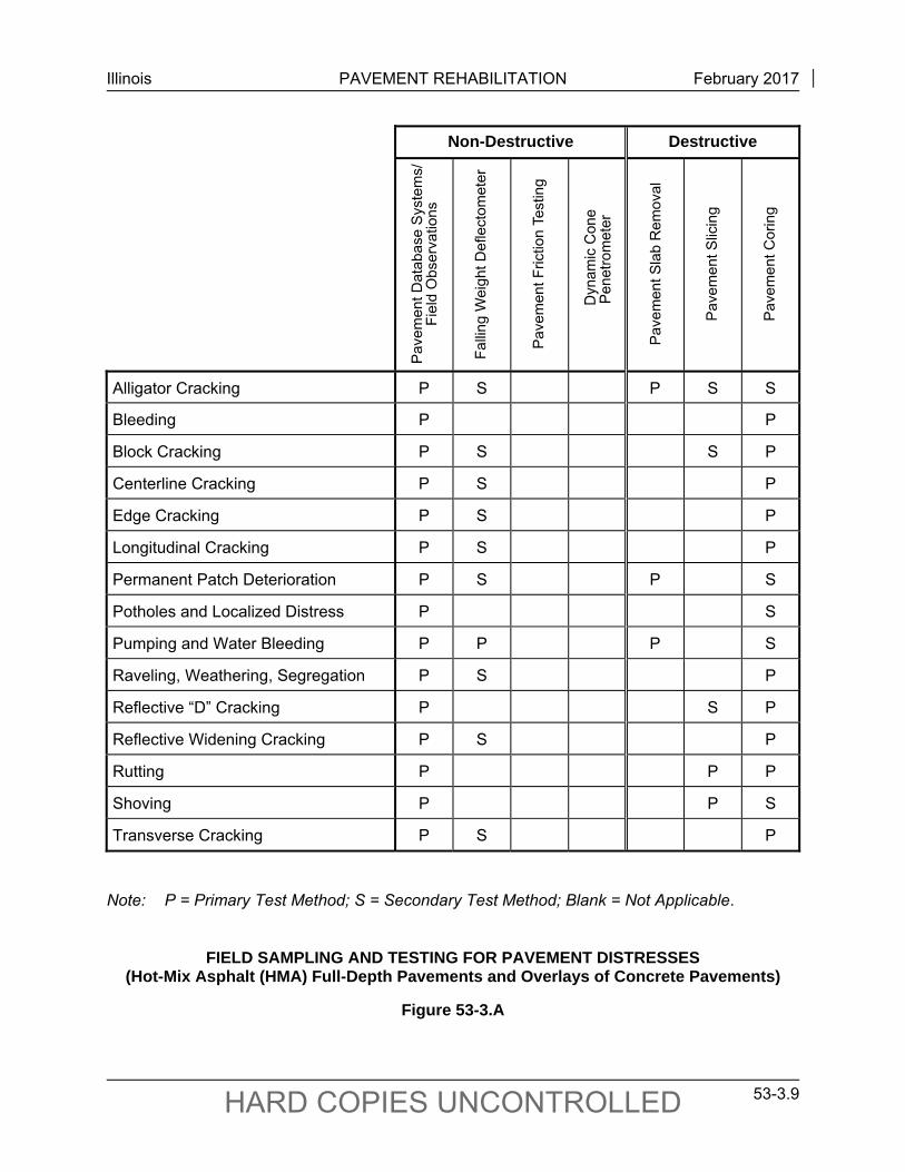
Illinois PAVEMENT REHABILITATION February 2017
53-3.9 HARD COPIES UNCONTROLLED
Non-Destructive Destructive
Alligator Cracking P S P S S
Bleeding P P
Block Cracking P S S P
Centerline Cracking P S P
Edge Cracking P S P
Longitudinal Cracking P S P
Permanent Patch Deterioration P S P S
Potholes and Localized Distress P S
Pumping and Water Bleeding P P P S
Raveling, Weathering, Segregation P S P
Reflective “D” Cracking P S P
Reflective Widening Cracking P S P
Rutting P P P
Shoving P P S
Transverse Cracking P S P
Note: P = Primary Test Method; S = Secondary Test Method; Blank = Not Applicable.
FIELD SAMPLING AND TESTING FOR PAVEMENT DISTRESSES
(Hot-Mix Asphalt (HMA) Full-Depth Pavements and Overlays of Concrete Pavements)
Figure 53-3.A
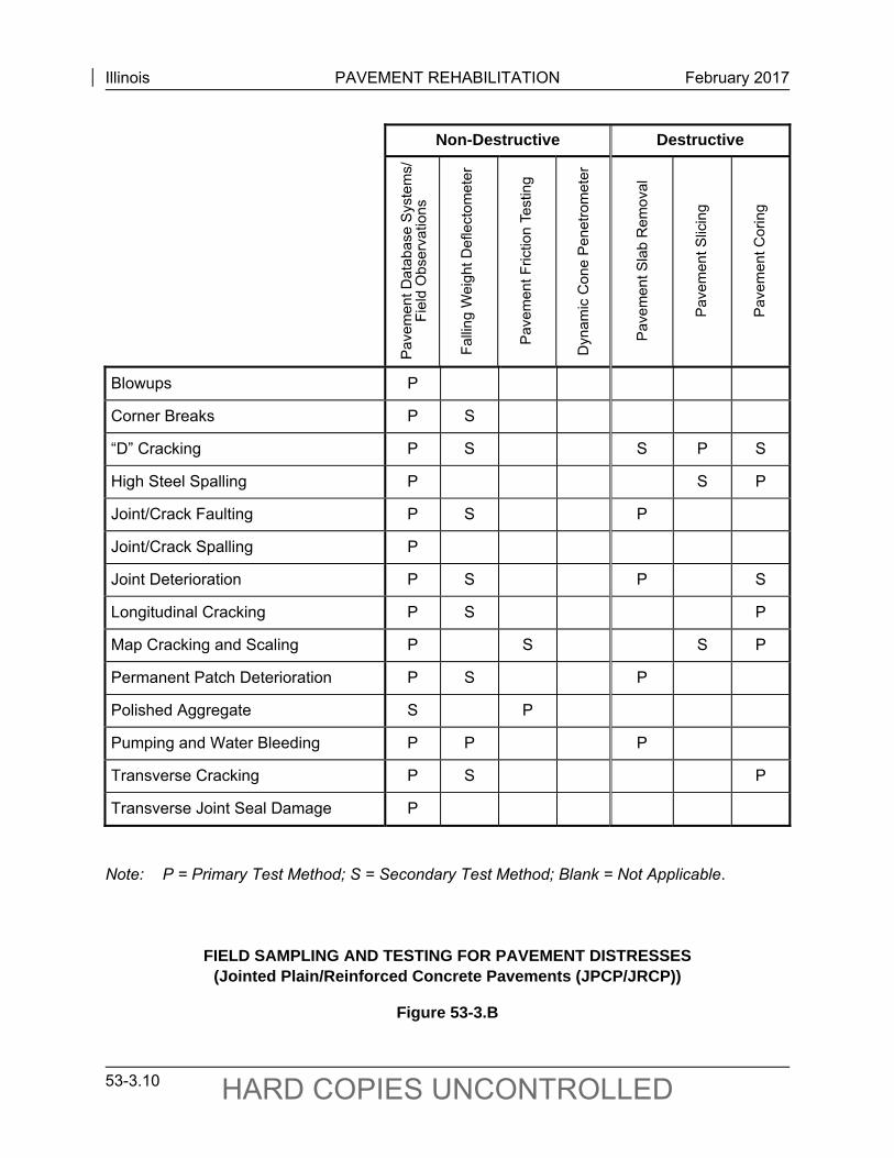
Illinois PAVEMENT REHABILITATION February 2017
53-3.10 HARD COPIES UNCONTROLLED
Non-Destructive Destructive
Blowups P
Corner Breaks P S
“D” Cracking P S S P S
High Steel Spalling P S P
Joint/Crack Faulting P S P
Joint/Crack Spalling P
Joint Deterioration P S P S
Longitudinal Cracking P S P
Map Cracking and Scaling P S S P
Permanent Patch Deterioration P S P
Polished Aggregate S P
Pumping and Water Bleeding P P P
Transverse Cracking P S P
Transverse Joint Seal Damage P
Note: P = Primary Test Method; S = Secondary Test Method; Blank = Not Applicable.
FIELD SAMPLING AND TESTING FOR PAVEMENT DISTRESSES (Jointed Plain/Reinforced Concrete Pavements (JPCP/JRCP))
Figure 53-3.B
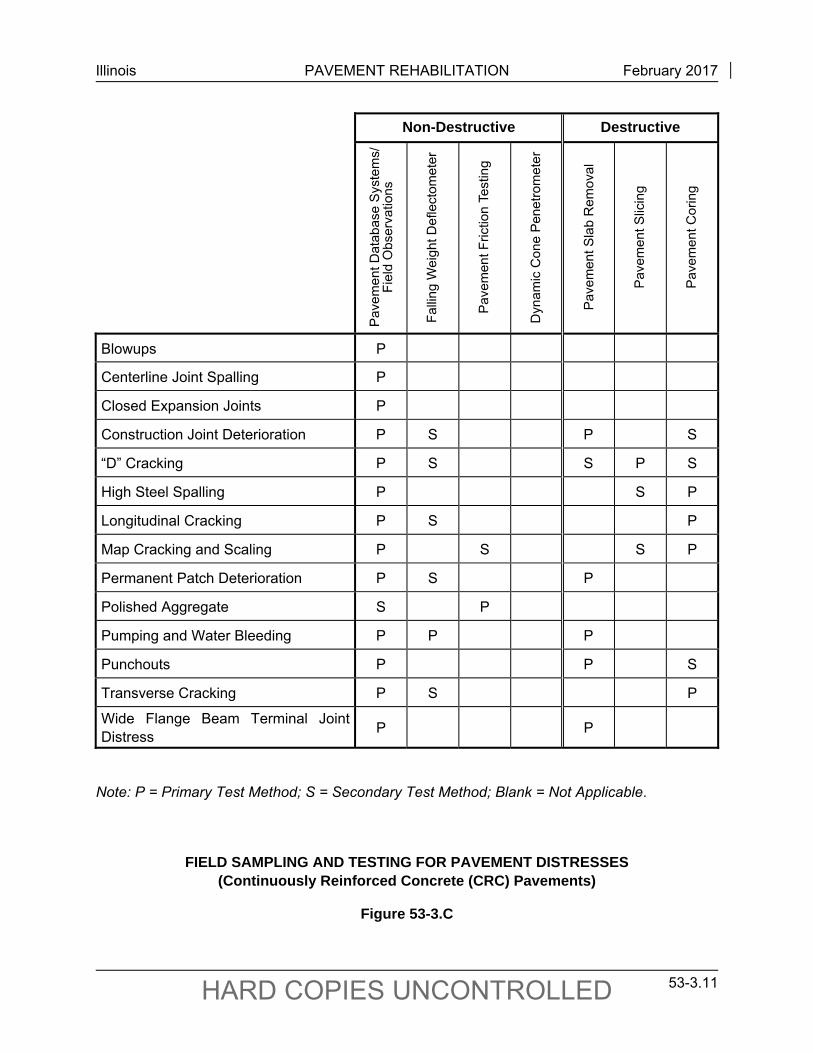
Illinois PAVEMENT REHABILITATION February 2017
53-3.11 HARD COPIES UNCONTROLLED
Non-Destructive Destructive
Blowups P
Centerline Joint Spalling P
Closed Expansion Joints P
Construction Joint Deterioration P S P S
“D” Cracking P S S P S
High Steel Spalling P S P
Longitudinal Cracking P S P
Map Cracking and Scaling P S S P
Permanent Patch Deterioration P S P
Polished Aggregate S P
Pumping and Water Bleeding P P P
Punchouts P P S
Transverse Cracking P S P
Wide Flange Beam Terminal Joint Distress
P P
Note: P = Primary Test Method; S = Secondary Test Method; Blank = Not Applicable.
FIELD SAMPLING AND TESTING FOR PAVEMENT DISTRESSES (Continuously Reinforced Concrete (CRC) Pavements)
Figure 53-3.C
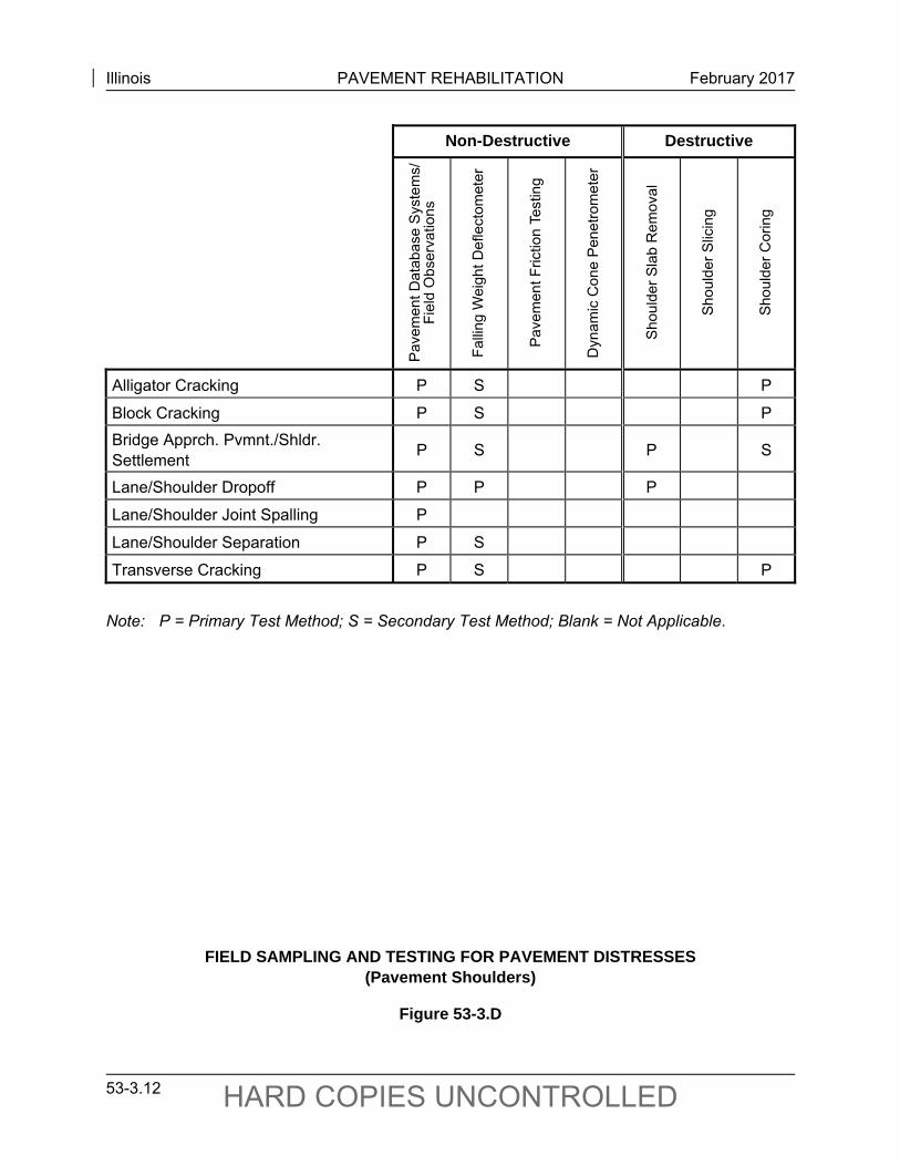
Illinois PAVEMENT REHABILITATION February 2017
53-3.12 HARD COPIES UNCONTROLLED
Non-Destructive Destructive
Alligator Cracking P S P
Block Cracking P S P
Bridge Apprch. Pvmnt./Shldr. Settlement
P S P S
Lane/Shoulder Dropoff P P P
Lane/Shoulder Joint Spalling P
Lane/Shoulder Separation P S
Transverse Cracking P S P
Note: P = Primary Test Method; S = Secondary Test Method; Blank = Not Applicable.
FIELD SAMPLING AND TESTING FOR PAVEMENT DISTRESSES
(Pavement Shoulders)
Figure 53-3.D
Illinois PAVEMENT REHABILITATION February 2017
53-3.13 HARD COPIES UNCONTROLLED
53-3.08 Guidelines for Material Sampling and Testing of Existing Hot-Mix Asphalt
The procedures that follow primarily apply to Hot-Mix Asphalt (HMA) overlays of concrete pavements; however, they can also be applied to full-depth HMA pavements if necessary. Contact the CBM to apply them to full-depth HMA pavement.
The performance and life-span of HMA overlays are subject to numerous variables in Illinois. Poor performance may result from:
a poor design, improper mixture selection, poor quality control of mixture production, poor construction practices, inadequate attention to the existing pavement/overlay conditions, severe overloads, and/or inadequate drainage.
Poor performance may be in the form of rutting, cracking, raveling, and potholing of the HMA overlay.
The typical life-span for a first generation HMA overlay in Illinois is between 12 and 15 years. The life-span of each subsequent HMA overlay is typically reduced from the life-span of the previous HMA overlay. The performance of thin lift overlays, or preventive maintenance activities, is highly dependent upon the quality of the underlying materials. Also, pavements with high truck volumes require stable materials in underlying layers. Illinois history has shown that poor existing pavement conditions, not properly addressed during rehabilitation, can greatly reduce the life-span of a new HMA overlay.
To determine the proper rehabilitation strategy, guide selection of the HMA mixture, and avoid leaving poor performing materials in place, an investigation of the existing pavement shall be performed. This investigation is considered especially critical if plans are being developed to perform a partial-depth mill and overlay of an existing HMA overlay that will be subject to heavy truck traffic. This investigation includes coring the existing pavement followed by laboratory testing for basic volumetric, strength, and durability properties.
Communication between planning personnel, coring personnel, and laboratory personnel is critical for these investigations. The materials testing laboratory shall be contacted prior to the coring operation to ensure that the cores will be tested in the appropriate time frame. In addition, once the testing is complete the materials personnel shall report the results back to the planning personnel with an explanation of the test results.
These guidelines provide assistance to the district planning and materials sections on the appropriate sampling and testing requirements that shall be completed prior to determining a rehabilitation strategy for concrete pavements with HMA overlay(s). Since older in situ mixes can have a variety of durability problems, the designer shall take the approach that on interstate and high-volume primary routes the existing HMA must be removed and the PCC surface must
Illinois PAVEMENT REHABILITATION February 2017
53-3.14 HARD COPIES UNCONTROLLED
be textured by milling, unless it can be proven otherwise. Leaving a 1 in. layer or less of HMA binder course over the PCC pavement is a poor engineering practice.
These guidelines shall be incorporated into the design of all HMA overlays whether the rehabilitation is a single-lift, a standard thickness with two lifts, or a structural overlay. These guidelines shall be followed on all Interstate overlays, sections serving heavily loaded trucks, and pavement sections that have a history of rutting problems. Questions and comments concerning the HMA investigation process may be directed to the HMA Operations Engineer of the CBM.
53-3.08(a) Pavement Coring Process
The pavement coring shall include all of the existing HMA layers and the original concrete pavement. Extreme care shall be used during the extraction process to avoid damaging the core. Screwdrivers, pry bars, and other devices that apply a concentrated force shall not be used as they will damage the cores. If a core sample is damaged by the extraction process, a replacement core shall be taken. Figure 53-3.E is a flowchart outlining the material testing procedures for cores taken from existing pavements.
Form BMPR 11176A “Existing HMA Pavement and Overlay Evaluation Materials Collection Field Report” shall be completed for each core location. Important information on the report includes project information, coring information, and other observations. Once removed, the cores shall be cleaned, blotted dry with a cloth rag to remove excess water, and clearly labeled. The label information shall include the core location, core number, and lift position. Once labeled, each core shall be sealed in a water-tight bag to minimize moisture loss and preserve the in situ condition. Allowing cores to dry will provide false data and can lead to a gross over-estimate of material strength.
The core samples shall then be taken to the appropriate laboratory for testing. It is advised that the cores be placed in a freezer after being delivered to the testing laboratory. Freezing aids in separating the core lifts from each other and allows the cores to remain nearly unchanged from the in situ condition. Return the core samples to the bags as soon as possible after separating lifts. The core samples shall remain bagged until they are tested. The core samples shall be tested as soon as possible after coring in order to acquire the most accurate result for the in situ condition of the material.
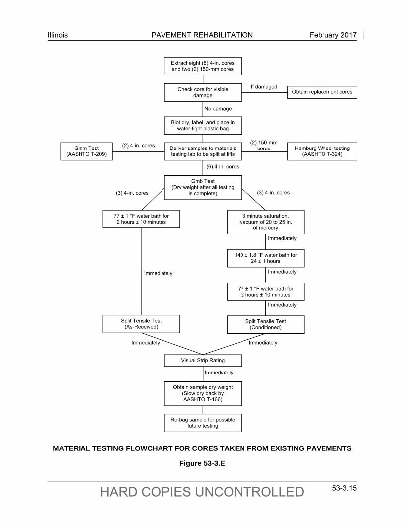
Illinois PAVEMENT REHABILITATION February 2017
53-3.15 HARD COPIES UNCONTROLLED
MATERIAL TESTING FLOWCHART FOR CORES TAKEN FROM EXISTING PAVEMENTS
Figure 53-3.E
(2) 150-mm cores
(3) 4-in. cores (3) 4-in. cores
Immediately Immediately
Immediately
Immediately
Immediately
Immediately
Immediately
(6) 4-in. cores
(2) 4-in. cores
No damage
Extract eight (8) 4-in. cores and two (2) 150-mm cores
Check core for visible damage
Blot dry, label, and place in water-tight plastic bag
Obtain replacement cores
Gmm Test (AASHTO T-209)
Deliver samples to materials testing lab to be split at lifts
Gmb Test (Dry weight after all testing
is complete)
Re-bag sample for possible future testing
Visual Strip Rating
140 ± 1.8 °F water bath for 24 ± 1 hours
77 ± 1 °F water bath for 2 hours ± 10 minutes
Split Tensile Test (Conditioned)
77 ± 1 °F water bath for 2 hours ± 10 minutes
Split Tensile Test (As-Received)
3 minute saturation. Vacuum of 20 to 25 in.
of mercury
If damaged
Obtain sample dry weight (Slow dry back by AASHTO T-166)
Hamburg Wheel testing (AASHTO T-324)
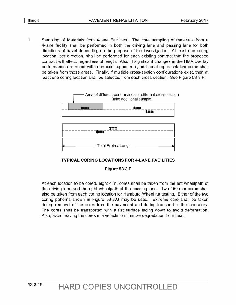
Illinois PAVEMENT REHABILITATION February 2017
53-3.16 HARD COPIES UNCONTROLLED
1. Sampling of Materials from 4-lane Facilities. The core sampling of materials from a
4-lane facility shall be performed in both the driving lane and passing lane for both directions of travel depending on the purpose of the investigation. At least one coring location, per direction, shall be performed for each existing contract that the proposed contract will affect, regardless of length. Also, if significant changes in the HMA overlay performance are noted within an existing contract, additional representative cores shall be taken from those areas. Finally, if multiple cross-section configurations exist, then at least one coring location shall be selected from each cross-section. See Figure 53-3.F.
TYPICAL CORING LOCATIONS FOR 4-LANE FACILITIES
Figure 53-3.F
At each location to be cored, eight 4 in. cores shall be taken from the left wheelpath of the driving lane and the right wheelpath of the passing lane. Two 150-mm cores shall also be taken from each coring location for Hamburg Wheel rut testing. Either of the two coring patterns shown in Figure 53-3.G may be used. Extreme care shall be taken during removal of the cores from the pavement and during transport to the laboratory. The cores shall be transported with a flat surface facing down to avoid deformation. Also, avoid leaving the cores in a vehicle to minimize degradation from heat.
Area of different performance or different cross-section (take additional sample)
Total Project Length
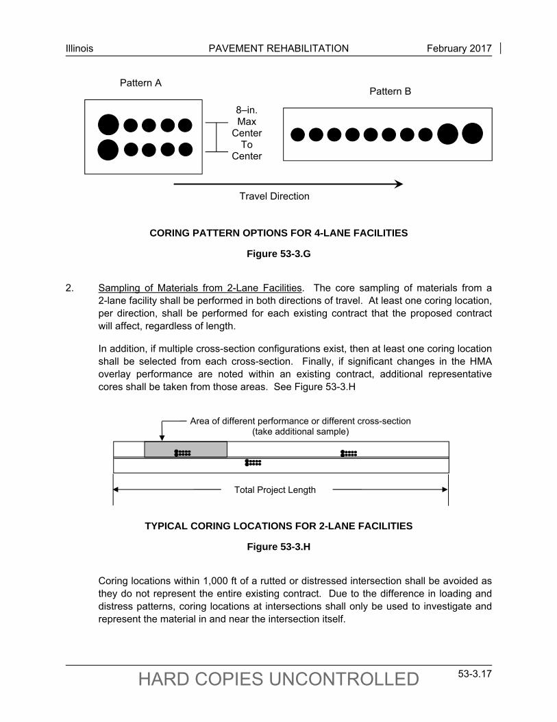
Illinois PAVEMENT REHABILITATION February 2017
53-3.17 HARD COPIES UNCONTROLLED
CORING PATTERN OPTIONS FOR 4-LANE FACILITIES
Figure 53-3.G
2. Sampling of Materials from 2-Lane Facilities. The core sampling of materials from a
2-lane facility shall be performed in both directions of travel. At least one coring location, per direction, shall be performed for each existing contract that the proposed contract will affect, regardless of length.
In addition, if multiple cross-section configurations exist, then at least one coring location shall be selected from each cross-section. Finally, if significant changes in the HMA overlay performance are noted within an existing contract, additional representative cores shall be taken from those areas. See Figure 53-3.H
TYPICAL CORING LOCATIONS FOR 2-LANE FACILITIES
Figure 53-3.H
Coring locations within 1,000 ft of a rutted or distressed intersection shall be avoided as they do not represent the entire existing contract. Due to the difference in loading and distress patterns, coring locations at intersections shall only be used to investigate and represent the material in and near the intersection itself.
Pattern A
Travel Direction
Pattern B
8–in. Max
Center To
Center
Total Project Length
Area of different performance or different cross-section (take additional sample)
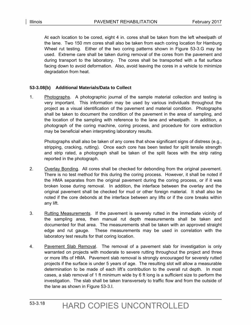
Illinois PAVEMENT REHABILITATION February 2017
53-3.18 HARD COPIES UNCONTROLLED
At each location to be cored, eight 4 in. cores shall be taken from the left wheelpath of the lane. Two 150 mm cores shall also be taken from each coring location for Hamburg Wheel rut testing. Either of the two coring patterns shown in Figure 53-3.G may be used. Extreme care shall be taken during removal of the cores from the pavement and during transport to the laboratory. The cores shall be transported with a flat surface facing down to avoid deformation. Also, avoid leaving the cores in a vehicle to minimize degradation from heat.
53-3.08(b) Additional Materials/Data to Collect
1. Photographs. A photographic journal of the sample material collection and testing is very important. This information may be used by various individuals throughout the project as a visual identification of the pavement and material condition. Photographs shall be taken to document the condition of the pavement in the area of sampling, and the location of the sampling with reference to the lane and wheelpath. In addition, a photograph of the coring machine, coring process, and procedure for core extraction may be beneficial when interpreting laboratory results.
Photographs shall also be taken of any cores that show significant signs of distress (e.g., stripping, cracking, rutting). Once each core has been tested for split tensile strength and strip rated, a photograph shall be taken of the split faces with the strip rating reported in the photograph.
2. Overlay Bonding. All cores shall be checked for debonding from the original pavement. There is no test method for this during the coring process. However, it shall be noted if the HMA separates from the original pavement during the coring process, or if it was broken loose during removal. In addition, the interface between the overlay and the original pavement shall be checked for mud or other foreign material. It shall also be noted if the core debonds at the interface between any lifts or if the core breaks within any lift.
3. Rutting Measurements. If the pavement is severely rutted in the immediate vicinity of the sampling area, then manual rut depth measurements shall be taken and documented for that area. The measurements shall be taken with an approved straight edge and rut gauge. These measurements may be used in correlation with the laboratory test results for that coring location.
4. Pavement Slab Removal. The removal of a pavement slab for investigation is only warranted on projects with moderate to severe rutting throughout the project and three or more lifts of HMA. Pavement slab removal is strongly encouraged for severely rutted projects if the surface is under 5 years of age. The resulting slot will allow a measurable determination to be made of each lift’s contribution to the overall rut depth. In most cases, a slab removal of 1 ft minimum wide by 6 ft long is a sufficient size to perform the investigation. The slab shall be taken transversely to traffic flow and from the outside of the lane as shown in Figure 53-3.I.
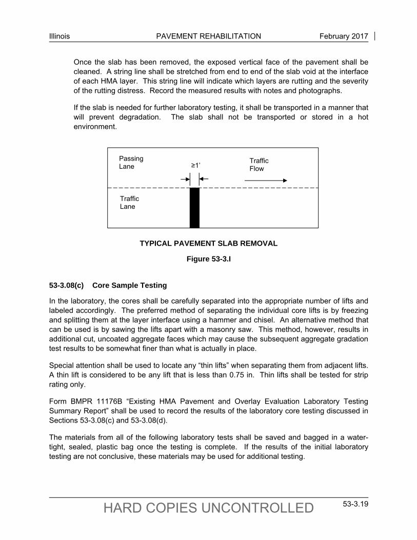
Illinois PAVEMENT REHABILITATION February 2017
53-3.19 HARD COPIES UNCONTROLLED
Once the slab has been removed, the exposed vertical face of the pavement shall be cleaned. A string line shall be stretched from end to end of the slab void at the interface of each HMA layer. This string line will indicate which layers are rutting and the severity of the rutting distress. Record the measured results with notes and photographs.
If the slab is needed for further laboratory testing, it shall be transported in a manner that will prevent degradation. The slab shall not be transported or stored in a hot environment.
TYPICAL PAVEMENT SLAB REMOVAL
Figure 53-3.I
53-3.08(c) Core Sample Testing
In the laboratory, the cores shall be carefully separated into the appropriate number of lifts and labeled accordingly. The preferred method of separating the individual core lifts is by freezing and splitting them at the layer interface using a hammer and chisel. An alternative method that can be used is by sawing the lifts apart with a masonry saw. This method, however, results in additional cut, uncoated aggregate faces which may cause the subsequent aggregate gradation test results to be somewhat finer than what is actually in place.
Special attention shall be used to locate any “thin lifts” when separating them from adjacent lifts. A thin lift is considered to be any lift that is less than 0.75 in. Thin lifts shall be tested for strip rating only.
Form BMPR 11176B “Existing HMA Pavement and Overlay Evaluation Laboratory Testing Summary Report” shall be used to record the results of the laboratory core testing discussed in Sections 53-3.08(c) and 53-3.08(d).
The materials from all of the following laboratory tests shall be saved and bagged in a water-tight, sealed, plastic bag once the testing is complete. If the results of the initial laboratory testing are not conclusive, these materials may be used for additional testing.
≥1’TrafficFlow
Passing Lane
Traffic Lane
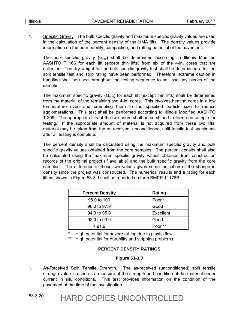
Illinois PAVEMENT REHABILITATION February 2017
53-3.20 HARD COPIES UNCONTROLLED
1. Specific Gravity. The bulk specific gravity and maximum specific gravity values are used in the calculation of the percent density of the HMA lifts. The density values provide information on the permeability, compaction, and rutting potential of the pavement.
The bulk specific gravity (Gmb) shall be determined according to Illinois Modified AASHTO T 166 for each lift (except thin lifts) from six of the 4-in. cores that are collected. The dry weight for the bulk specific gravity test shall be determined after the split tensile test and strip rating have been performed. Therefore, extreme caution in handling shall be used throughout the testing sequence to not lose any pieces of the sample.
The maximum specific gravity (Gmm) for each lift (except thin lifts) shall be determined from the material of the remaining two 4-in. cores. This involves heating cores in a low temperature oven and crumbling them to the specified particle size to reduce agglomerations. This test shall be performed according to Illinois Modified AASHTO T 209. The appropriate lifts of the two cores shall be combined to form one sample for testing. If the appropriate amount of material is not acquired from these two lifts, material may be taken from the as-received, unconditioned, split tensile test specimens after all testing is complete.
The percent density shall be calculated using the maximum specific gravity and bulk specific gravity values obtained from the core samples. The percent density shall also be calculated using the maximum specific gravity values obtained from construction records of the original project (if available) and the bulk specific gravity from the core samples. The difference in these two values gives some indication of the change in density since the project was constructed. The numerical results and a rating for each lift as shown in Figure 53-3.J shall be reported on form BMPR 11176B.
Percent Density Rating 98.0 to 100 Poor *
96.0 to 97.9 Good
94.0 to 95.9 Excellent
92.0 to 93.9 Good
< 91.9 Poor **
* High potential for severe rutting due to plastic flow. ** High potential for durability and stripping problems.
PERCENT DENSITY RATINGS
Figure 53-3.J
1. As-Received Split Tensile Strength. The as-received (unconditioned) split tensile strength value is used as a measure of the strength and condition of the material under current in situ conditions. This test provides information on the condition of the pavement at the time of the investigation.
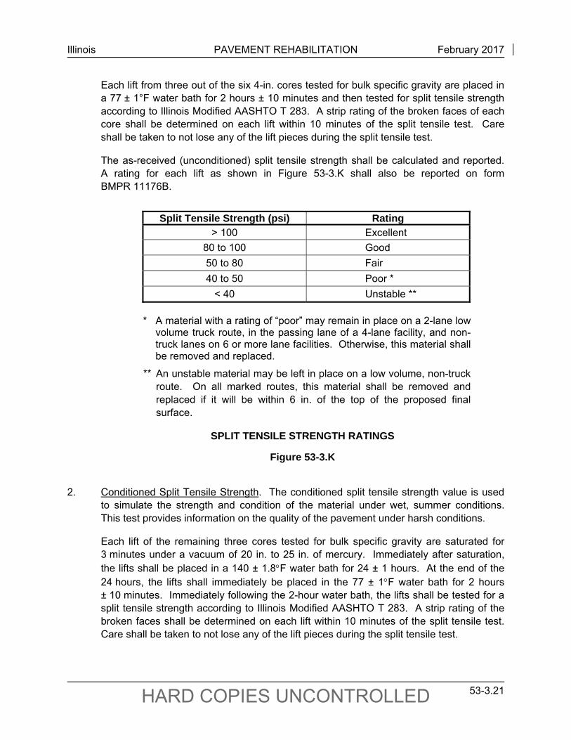
Illinois PAVEMENT REHABILITATION February 2017
53-3.21 HARD COPIES UNCONTROLLED
Each lift from three out of the six 4-in. cores tested for bulk specific gravity are placed in a 77 ± 1°F water bath for 2 hours ± 10 minutes and then tested for split tensile strength according to Illinois Modified AASHTO T 283. A strip rating of the broken faces of each core shall be determined on each lift within 10 minutes of the split tensile test. Care shall be taken to not lose any of the lift pieces during the split tensile test.
The as-received (unconditioned) split tensile strength shall be calculated and reported. A rating for each lift as shown in Figure 53-3.K shall also be reported on form BMPR 11176B.
Split Tensile Strength (psi) Rating
> 100 Excellent
80 to 100 Good
50 to 80 Fair
40 to 50 Poor *
< 40 Unstable **
* A material with a rating of “poor” may remain in place on a 2-lane low
volume truck route, in the passing lane of a 4-lane facility, and non-truck lanes on 6 or more lane facilities. Otherwise, this material shall be removed and replaced.
** An unstable material may be left in place on a low volume, non-truck route. On all marked routes, this material shall be removed and replaced if it will be within 6 in. of the top of the proposed final surface.
SPLIT TENSILE STRENGTH RATINGS
Figure 53-3.K
2. Conditioned Split Tensile Strength. The conditioned split tensile strength value is used
to simulate the strength and condition of the material under wet, summer conditions. This test provides information on the quality of the pavement under harsh conditions.
Each lift of the remaining three cores tested for bulk specific gravity are saturated for 3 minutes under a vacuum of 20 in. to 25 in. of mercury. Immediately after saturation, the lifts shall be placed in a 140 ± 1.8F water bath for 24 ± 1 hours. At the end of the 24 hours, the lifts shall immediately be placed in the 77 ± 1F water bath for 2 hours ± 10 minutes. Immediately following the 2-hour water bath, the lifts shall be tested for a split tensile strength according to Illinois Modified AASHTO T 283. A strip rating of the broken faces shall be determined on each lift within 10 minutes of the split tensile test. Care shall be taken to not lose any of the lift pieces during the split tensile test.
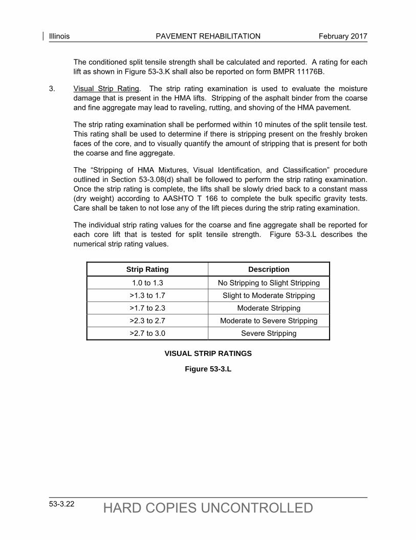
Illinois PAVEMENT REHABILITATION February 2017
53-3.22 HARD COPIES UNCONTROLLED
The conditioned split tensile strength shall be calculated and reported. A rating for each lift as shown in Figure 53-3.K shall also be reported on form BMPR 11176B.
3. Visual Strip Rating. The strip rating examination is used to evaluate the moisture damage that is present in the HMA lifts. Stripping of the asphalt binder from the coarse and fine aggregate may lead to raveling, rutting, and shoving of the HMA pavement.
The strip rating examination shall be performed within 10 minutes of the split tensile test. This rating shall be used to determine if there is stripping present on the freshly broken faces of the core, and to visually quantify the amount of stripping that is present for both the coarse and fine aggregate.
The “Stripping of HMA Mixtures, Visual Identification, and Classification” procedure outlined in Section 53-3.08(d) shall be followed to perform the strip rating examination. Once the strip rating is complete, the lifts shall be slowly dried back to a constant mass (dry weight) according to AASHTO T 166 to complete the bulk specific gravity tests. Care shall be taken to not lose any of the lift pieces during the strip rating examination.
The individual strip rating values for the coarse and fine aggregate shall be reported for each core lift that is tested for split tensile strength. Figure 53-3.L describes the numerical strip rating values.
Strip Rating Description
1.0 to 1.3 No Stripping to Slight Stripping
>1.3 to 1.7 Slight to Moderate Stripping
>1.7 to 2.3 Moderate Stripping
>2.3 to 2.7 Moderate to Severe Stripping
>2.7 to 3.0 Severe Stripping
VISUAL STRIP RATINGS
Figure 53-3.L
Illinois PAVEMENT REHABILITATION February 2017
53-3.23 HARD COPIES UNCONTROLLED
53-3.08(d) Stripping of HMA Mixtures, Visual Identification, and Classification
The following instructions and procedure provide the means to rate the phenomenon known as stripping in numerical terms:
1. Instructions for Visual Strip Rating. The following instructions describe the method to be used for visually identifying and classifying the effect of moisture damage on the adhesion of asphalt binder to the aggregate in HMA mixtures:
a. This procedure shall only be applied to freshly split specimen faces (e.g., those obtained from split tensile testing). The observation of cored, sawed, or chiseled faces shall be avoided, as the true condition of the stripping will be obscured.
b. The rating shall be completed within 10 minutes of splitting for maximum clarity. When the specimens dry out, they may look considerably different. The aggregate surfaces shall be examined carefully to determine if the asphalt was stripped from the aggregate as a result of being “washed” by water before the specimen was split or if the asphalt binder was “ripped apart” near the asphalt binder/aggregate interface during the split tensile test. Also, aggregate surfaces with small, relatively isolated, globules of asphalt are quite likely not stripped.
c. Special attention shall be given to fractured and broken aggregates. Fractured aggregates are those that were cracked during compaction. These fractured aggregates will have a distinct face with a dull or discolored surface. Broken aggregates are those that were broken during the split tensile test. Broken aggregates often occur near the outside surface of the specimen where the compressive forces are greatest. These broken aggregates will also have a distinct broken face, but will have a bright, uncoated surface. The broken aggregates may be a continuation of a crack that was started during compaction. There is no evidence that a broken aggregate was broken entirely under the compressive force of the split tensile test.
d. Coarse aggregate particles shall be defined as those particles retained on the #8 sieve. Fine aggregate particles shall be defined as those particles that will pass through a #8 sieve.
e. When examining the split face, use the entire face area of all the fine particles separately from all the coarse particles on the split face to determine the percentage of the total area that is stripped. Do not use the percent of the area of each individual stone that is stripped to collectively determine the percentage of stripped aggregate particles on the entire split face of the specimen. Also, do not estimate the percentage of aggregate particles that are stripped based on the total number of aggregate particles. (i.e., a small stripped aggregate particle does not affect the entire specimen the same as a large stripped aggregate particle.)
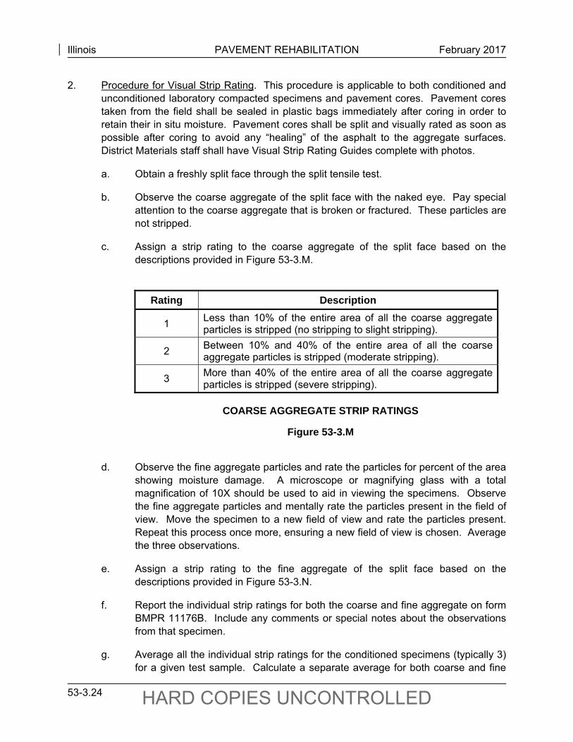
Illinois PAVEMENT REHABILITATION February 2017
53-3.24 HARD COPIES UNCONTROLLED
2. Procedure for Visual Strip Rating. This procedure is applicable to both conditioned and unconditioned laboratory compacted specimens and pavement cores. Pavement cores taken from the field shall be sealed in plastic bags immediately after coring in order to retain their in situ moisture. Pavement cores shall be split and visually rated as soon as possible after coring to avoid any “healing” of the asphalt to the aggregate surfaces. District Materials staff shall have Visual Strip Rating Guides complete with photos.
a. Obtain a freshly split face through the split tensile test.
b. Observe the coarse aggregate of the split face with the naked eye. Pay special attention to the coarse aggregate that is broken or fractured. These particles are not stripped.
c. Assign a strip rating to the coarse aggregate of the split face based on the descriptions provided in Figure 53-3.M.
Rating Description
1 Less than 10% of the entire area of all the coarse aggregate particles is stripped (no stripping to slight stripping).
2 Between 10% and 40% of the entire area of all the coarse aggregate particles is stripped (moderate stripping).
3 More than 40% of the entire area of all the coarse aggregate particles is stripped (severe stripping).
COARSE AGGREGATE STRIP RATINGS
Figure 53-3.M
d. Observe the fine aggregate particles and rate the particles for percent of the area
showing moisture damage. A microscope or magnifying glass with a total magnification of 10X should be used to aid in viewing the specimens. Observe the fine aggregate particles and mentally rate the particles present in the field of view. Move the specimen to a new field of view and rate the particles present. Repeat this process once more, ensuring a new field of view is chosen. Average the three observations.
e. Assign a strip rating to the fine aggregate of the split face based on the descriptions provided in Figure 53-3.N.
f. Report the individual strip ratings for both the coarse and fine aggregate on form BMPR 11176B. Include any comments or special notes about the observations from that specimen.
g. Average all the individual strip ratings for the conditioned specimens (typically 3) for a given test sample. Calculate a separate average for both coarse and fine
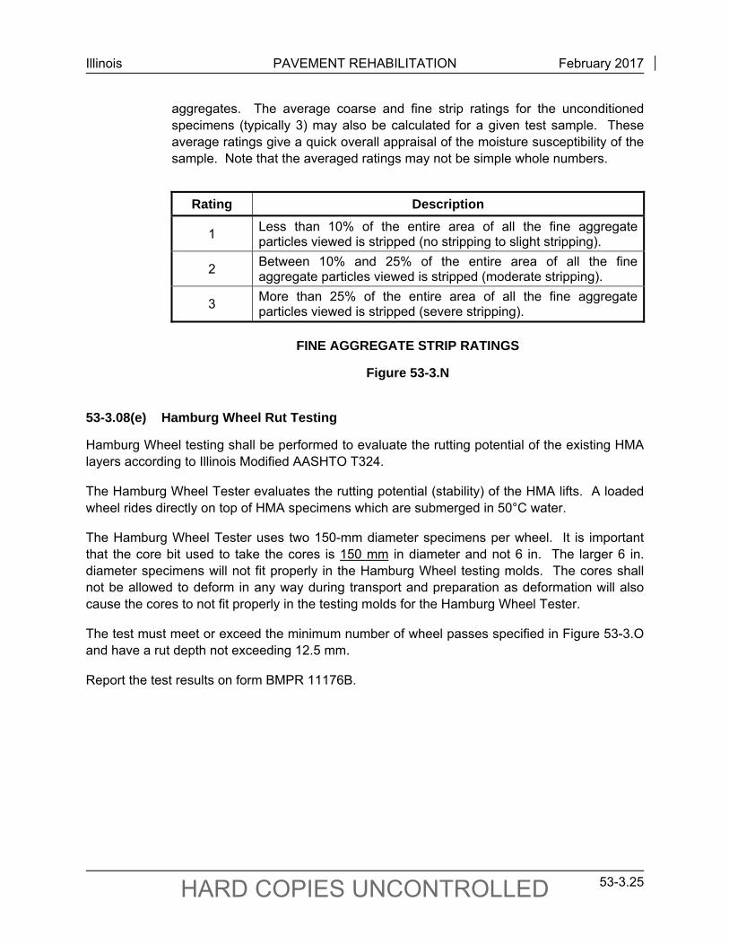
Illinois PAVEMENT REHABILITATION February 2017
53-3.25 HARD COPIES UNCONTROLLED
aggregates. The average coarse and fine strip ratings for the unconditioned specimens (typically 3) may also be calculated for a given test sample. These average ratings give a quick overall appraisal of the moisture susceptibility of the sample. Note that the averaged ratings may not be simple whole numbers.
Rating Description
1 Less than 10% of the entire area of all the fine aggregate particles viewed is stripped (no stripping to slight stripping).
2 Between 10% and 25% of the entire area of all the fine aggregate particles viewed is stripped (moderate stripping).
3 More than 25% of the entire area of all the fine aggregate particles viewed is stripped (severe stripping).
FINE AGGREGATE STRIP RATINGS
Figure 53-3.N
53-3.08(e) Hamburg Wheel Rut Testing
Hamburg Wheel testing shall be performed to evaluate the rutting potential of the existing HMA layers according to Illinois Modified AASHTO T324.
The Hamburg Wheel Tester evaluates the rutting potential (stability) of the HMA lifts. A loaded wheel rides directly on top of HMA specimens which are submerged in 50°C water.
The Hamburg Wheel Tester uses two 150-mm diameter specimens per wheel. It is important that the core bit used to take the cores is 150 mm in diameter and not 6 in. The larger 6 in. diameter specimens will not fit properly in the Hamburg Wheel testing molds. The cores shall not be allowed to deform in any way during transport and preparation as deformation will also cause the cores to not fit properly in the testing molds for the Hamburg Wheel Tester.
The test must meet or exceed the minimum number of wheel passes specified in Figure 53-3.O and have a rut depth not exceeding 12.5 mm.
Report the test results on form BMPR 11176B.
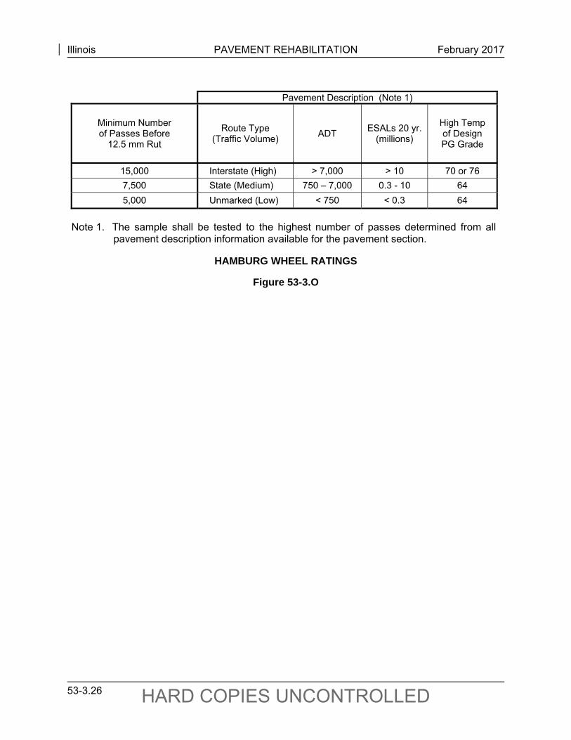
Illinois PAVEMENT REHABILITATION February 2017
53-3.26 HARD COPIES UNCONTROLLED
Pavement Description (Note 1)
Minimum Number of Passes Before
12.5 mm Rut
Route Type (Traffic Volume)
ADT ESALs 20 yr.
(millions)
High Temp of Design PG Grade
15,000 Interstate (High) > 7,000 > 10 70 or 76
7,500 State (Medium) 750 – 7,000 0.3 - 10 64
5,000 Unmarked (Low) < 750 < 0.3 64
Note 1. The sample shall be tested to the highest number of passes determined from all
pavement description information available for the pavement section.
HAMBURG WHEEL RATINGS
Figure 53-3.O
Illinois PAVEMENT REHABILITATION March 2017
53-4.1 HARD COPIES UNCONTROLLED
53-4 PAVEMENT REHABILITATION METHODS AND STRATEGIES
53-4.01 Pavement Rehabilitation Methods
A rehabilitation strategy normally is developed and targeted to address specific deficiencies with a particular pavement type. The strategy usually will be a combination of several rehabilitation techniques or methods that, when completed, will correct deficiencies (i.e., surface failure, structural failure, or both) in the most cost-effective manner. It is critical, therefore, that the designer understands the rehabilitation methods available and their specific applications. The following pages provide brief descriptions of the pavement rehabilitation methods typically used by the Department. Use these descriptions to better understand each rehabilitation method’s purpose and application when developing alternative rehabilitation strategies.
Illinois PAVEMENT REHABILITATION March 2017
53-4.2 HARD COPIES UNCONTROLLED
PAVEMENT REHABILITATION METHOD
Name: Hot-Mix Asphalt (HMA) Overlay (Policy Resurfacing Program)
Application: Pavement Type(s): All Pavements Distress Type(s): Relates to both Surface Failures and Structural Failures
Description and Purpose:
HMA overlays should be specified in accordance with the Department’s policy resurfacing program as discussed in Section 53-4.04. HMA mixture design criteria must be met as outlined in Section 53-4.07.
Special Considerations/Comments:
Consider a request for an additional thickness exception when there is evidence of large areas of structural failure. Consult BDE.
Illinois PAVEMENT REHABILITATION March 2017
53-4.3 HARD COPIES UNCONTROLLED
PAVEMENT REHABILITATION METHOD
Name: HMA Overlay (Structural)
Application: Pavement Type(s): All Pavements Distress Type(s): Structural Failures
Description and Purpose:
Structural HMA overlays should be designed and specified in accordance with the Department’s pavement design guidelines and procedures presented in Chapter 54. HMA mixture design criteria must be met as outlined in Section 53-4.07.
Special Considerations/Comments:
Structural overlays require BDE approval.
Illinois PAVEMENT REHABILITATION March 2017
53-4.4 HARD COPIES UNCONTROLLED
PAVEMENT REHABILITATION METHOD
Name: 3P Program
Application: Pavement Type(s): All Pavements (except Interstates) Distress Type(s): Relates to both Surface Failures and Structural Failures
Description and Purpose:
The 3P Program consists of repairing and resurfacing existing paved roadways. The 3P Program should be implemented in accordance with the procedures and guidelines presented in Section 53-4.03. HMA mixture design criteria must be met as outlined in Section 53-4.07.
Special Considerations/Comments:
The 3P Program is similar to the Policy Resurfacing Program in that the resurfacing thickness and life expectancy are the same; however, a 3P improvement is generally limited to the existing paved roadway (travel lanes plus HMA stabilized shoulders) and patching is limited to 10%.
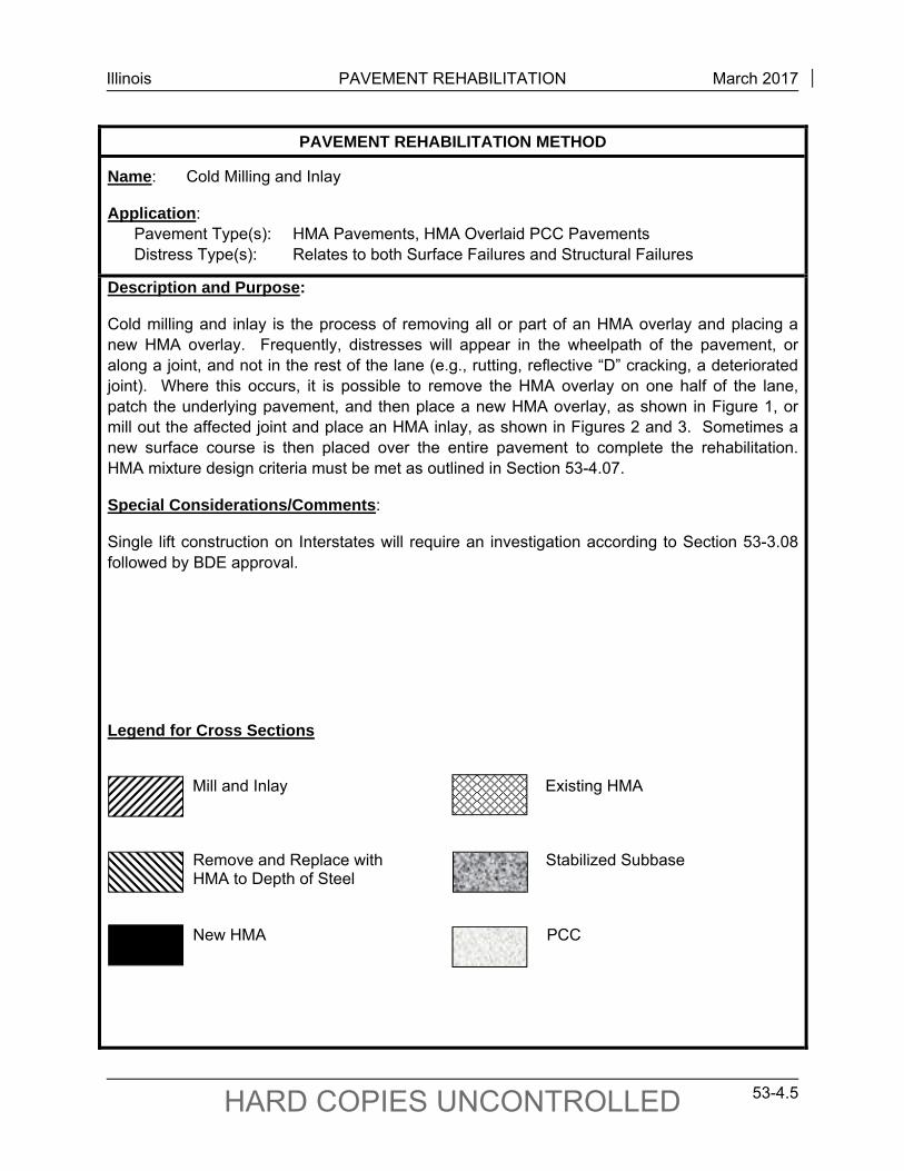
Illinois PAVEMENT REHABILITATION March 2017
53-4.5 HARD COPIES UNCONTROLLED
PAVEMENT REHABILITATION METHOD
Name: Cold Milling and Inlay
Application: Pavement Type(s): HMA Pavements, HMA Overlaid PCC Pavements Distress Type(s): Relates to both Surface Failures and Structural Failures
Description and Purpose:
Cold milling and inlay is the process of removing all or part of an HMA overlay and placing a new HMA overlay. Frequently, distresses will appear in the wheelpath of the pavement, or along a joint, and not in the rest of the lane (e.g., rutting, reflective “D” cracking, a deteriorated joint). Where this occurs, it is possible to remove the HMA overlay on one half of the lane, patch the underlying pavement, and then place a new HMA overlay, as shown in Figure 1, or mill out the affected joint and place an HMA inlay, as shown in Figures 2 and 3. Sometimes a new surface course is then placed over the entire pavement to complete the rehabilitation. HMA mixture design criteria must be met as outlined in Section 53-4.07.
Special Considerations/Comments:
Single lift construction on Interstates will require an investigation according to Section 53-3.08 followed by BDE approval.
Legend for Cross Sections
Mill and Inlay Existing HMA
Remove and Replace with Stabilized Subbase HMA to Depth of Steel
New HMA PCC
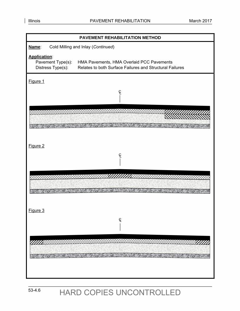
Illinois PAVEMENT REHABILITATION March 2017
53-4.6 HARD COPIES UNCONTROLLED
PAVEMENT REHABILITATION METHOD
Name: Cold Milling and Inlay (Continued)
Application: Pavement Type(s): HMA Pavements, HMA Overlaid PCC Pavements Distress Type(s): Relates to both Surface Failures and Structural Failures
Figure 1 Figure 2 Figure 3
C L
C L
C L
Illinois PAVEMENT REHABILITATION March 2017
53-4.7 HARD COPIES UNCONTROLLED
PAVEMENT REHABILITATION METHOD
Name: Reflective Crack Control
Application: Pavement Type(s): HMA Overlaid PCC Pavements and HMA Pavements Distress Type(s): Relates to Surface Failures
Description and Purpose:
On the basis of the results of field studies conducted by the Department, the following systems have been developed for reflective crack control (RCC) in conjunction with HMA overlays:
1. System A. System A is a non-woven reinforcing fabric (see the Standard Specifications) that is placed on a hot applied liquid asphalt binder over the prepared pavement surface.
2. System B. System B is a prefabricated waterproofing membrane interlayered with woven or non-woven reinforcing fabric that is embedded in a layer of self-adhesive plasticized bitumen (see the Standard Specifications). A primer that is compatible with the membrane is applied on the prepared pavement surface prior to placement of System B.
3. System C. System C is a nonproprietary asphalt-rubber waterproofing membrane interlayer and cover aggregate (see the Standard Specifications) that is placed at a specified application rate on the existing pavement surface.
4. System D. System D is a composite three-layer system composed of a low strength, non-woven, geotextile bottom layer, a viscoelastic membrane middle layer, and high strength, woven geotextile top layer (see the Standard Specifications). A tack coat compatible with the system is placed on the prepared surface prior to placement of System D.
Reflective crack control is classified by the following two general types:
1. Strip Reflective Crack Control (SRCC). SRCC is suitable for use on either rigid or flexible bases and should be considered for all projects that involve resurfacing of proposed or existing widening joints or where longitudinal reflective cracks would conflict with final traffic control markings thus causing confusion to the motorist. Pavement-paved shoulder joints should not be included unless the shoulder is tied to the pavement by means of an effective load-transfer device. Systems A and C should be a minimum of 24 in. wide for SRCC, and System B should be a minimum of 12 in. wide. If present, the SRCC material strip should completely cover alligator cracking.
2. Area Reflective Crack Control (ARCC). ARCC is suitable only for flexible bases (e.g., full-depth HMA, HMA surfaces over aggregate bases, HMA surfaces over deteriorated pozzolanic bases). ARCC is not capable of withstanding the transverse crack – producing thermal tensile stresses and vertical movements under traffic of a PCC pavement (rigid base). If transverse cracks or joints occur at intervals of less than 10 ft, the base (e.g. pozzolanic) can be treated as a flexible base. System B is not suitable for ARCC.
Illinois PAVEMENT REHABILITATION March 2017
53-4.8 HARD COPIES UNCONTROLLED
PAVEMENT REHABILITATION METHOD
Name: Reflective Crack Control (Continued)
Application: Pavement Type(s): HMA Overlaid PCC Pavements and HMA Pavements Distress Type(s): Relates to Surface Failures
RCC Systems A, B, C, and D require a smooth substrate. All cracks should be sealed and depressions should be filled before placing any RCC material. Place Systems A and B materials as low as practical in the pavement structure. However, if after crack sealing and patching, the surface remains uneven for RCC material placement, a leveling binder should be used. System C, being a liquid system, is more forgiving of a rough substrate but, also, occasionally, may require a leveling binder before placement.
Illinois PAVEMENT REHABILITATION March 2017
53-4.9 HARD COPIES UNCONTROLLED
PAVEMENT REHABILITATION METHOD
Name: Full-Depth CRCP Patches (Class A)
Application: Pavement Type(s): CRCP, HMA Overlaid CRCP Distress Type(s): Structural Failures
Description and Purpose:
Class A patching consists of removing the failed pavement area and patching it with a full-depth continuously reinforced PCC patch. Where CRCP facilities are to be patched, it is important to make every attempt to maintain the integrity of the continuous reinforcement. A decision that the pavement distress is so severe that continuity cannot be maintained must be justified by district field testing and subsequent review by the Central Office. In some cases, previous contracts or maintenance activities may have resulted in the use of non-tied PCC or HMA concrete patches being placed on a CRCP facility. Such patches should be replaced with Class A patches when rehabilitation is justified. Obtain BDE approval prior to specifying other than Class A patching for CRCP facilities. Refer to the Highway Standards for Class A patching details. The minimum Class A patch dimensions will be a length of 4.50 ft and a width that includes half the width of the travel lane.
Special Considerations/Comments:
It is not desirable to create the large number of closely spaced joints in a pavement that would result from placing a large number of closely spaced patches. The minimum distance between patches is 15 ft. If less than 15 ft of existing pavement will remain, the entire area between the two patches should be removed and replaced.
If PCC patching is specified on Federal-aid projects, specify the use of an early strength patching mix. Consider early strength patching mix on State-only projects, two-lane, two-way facilities, and multi-lane highways where it is not desirable to close a lane overnight or other traffic control concerns exist. Note that it is very important to specify early strength patching mix for CRCP Class A patching to minimize steel movement in the patch as it cures.
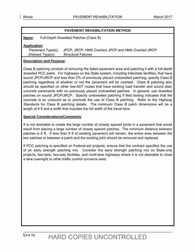
Illinois PAVEMENT REHABILITATION March 2017
53-4.10 HARD COPIES UNCONTROLLED
PAVEMENT REHABILITATION METHOD
Name: Full-Depth Dowelled Patches (Class B)
Application: Pavement Type(s): JPCP, JRCP, HMA Overlaid JPCP and HMA Overlaid JRCP Distress Type(s): Structural Failures
Description and Purpose:
Class B patching consists of removing the failed pavement area and patching it with a full-depth dowelled PCC patch. For highways on the State system, including Interstate facilities, that have sound JPCP/JRCP and less than 2% of previously placed undowelled patching, specify Class B patching regardless of whether or not the pavement will be overlaid. Class B patching also should be specified on other low-ADT routes that have existing load transfer and sound plain concrete pavements with no previously placed undowelled patches. In general, use dowelled patches on sound JPCP/JRCP. Specify undowelled patching if field testing indicates that the concrete is so unsound as to preclude the use of Class B patching. Refer to the Highway Standards for Class B patching details. The minimum Class B patch dimensions will be a length of 6 ft and a width that includes the full width of the travel lane.
Special Considerations/Comments:
It is not desirable to create the large number of closely spaced joints in a pavement that would result from placing a large number of closely spaced patches. The minimum distance between patches is 6 ft. If less than 6 ft of existing pavement will remain, the entire area between the two patches or between a patch and the existing joint should be removed and replaced.
If PCC patching is specified on Federal-aid projects, ensure that the contract specifies the use of an early strength patching mix. Consider the early strength patching mix on State-only projects, two-lane, two-way facilities, and multi-lane highways where it is not desirable to close a lane overnight or other traffic control concerns exist.
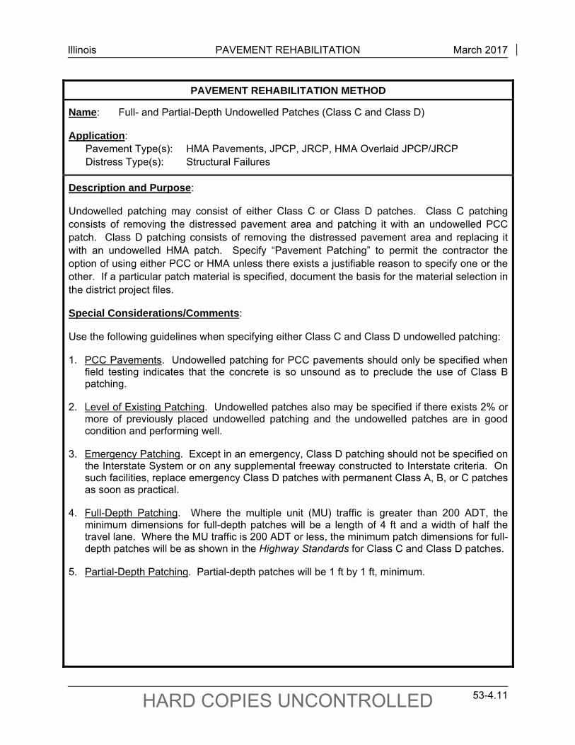
Illinois PAVEMENT REHABILITATION March 2017
53-4.11 HARD COPIES UNCONTROLLED
PAVEMENT REHABILITATION METHOD
Name: Full- and Partial-Depth Undowelled Patches (Class C and Class D)
Application: Pavement Type(s): HMA Pavements, JPCP, JRCP, HMA Overlaid JPCP/JRCP Distress Type(s): Structural Failures
Description and Purpose:
Undowelled patching may consist of either Class C or Class D patches. Class C patching consists of removing the distressed pavement area and patching it with an undowelled PCC patch. Class D patching consists of removing the distressed pavement area and replacing it with an undowelled HMA patch. Specify “Pavement Patching” to permit the contractor the option of using either PCC or HMA unless there exists a justifiable reason to specify one or the other. If a particular patch material is specified, document the basis for the material selection in the district project files.
Special Considerations/Comments:
Use the following guidelines when specifying either Class C and Class D undowelled patching:
1. PCC Pavements. Undowelled patching for PCC pavements should only be specified when field testing indicates that the concrete is so unsound as to preclude the use of Class B patching.
2. Level of Existing Patching. Undowelled patches also may be specified if there exists 2% or more of previously placed undowelled patching and the undowelled patches are in good condition and performing well.
3. Emergency Patching. Except in an emergency, Class D patching should not be specified on the Interstate System or on any supplemental freeway constructed to Interstate criteria. On such facilities, replace emergency Class D patches with permanent Class A, B, or C patches as soon as practical.
4. Full-Depth Patching. Where the multiple unit (MU) traffic is greater than 200 ADT, the minimum dimensions for full-depth patches will be a length of 4 ft and a width of half the travel lane. Where the MU traffic is 200 ADT or less, the minimum patch dimensions for full-depth patches will be as shown in the Highway Standards for Class C and Class D patches.
5. Partial-Depth Patching. Partial-depth patches will be 1 ft by 1 ft, minimum.
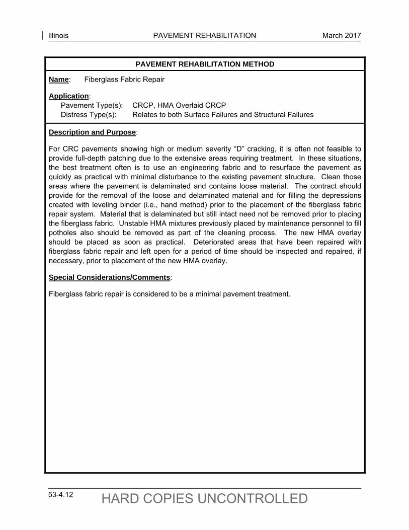
Illinois PAVEMENT REHABILITATION March 2017
53-4.12 HARD COPIES UNCONTROLLED
PAVEMENT REHABILITATION METHOD
Name: Fiberglass Fabric Repair
Application: Pavement Type(s): CRCP, HMA Overlaid CRCP Distress Type(s): Relates to both Surface Failures and Structural Failures
Description and Purpose:
For CRC pavements showing high or medium severity “D” cracking, it is often not feasible to provide full-depth patching due to the extensive areas requiring treatment. In these situations, the best treatment often is to use an engineering fabric and to resurface the pavement as quickly as practical with minimal disturbance to the existing pavement structure. Clean those areas where the pavement is delaminated and contains loose material. The contract should provide for the removal of the loose and delaminated material and for filling the depressions created with leveling binder (i.e., hand method) prior to the placement of the fiberglass fabric repair system. Material that is delaminated but still intact need not be removed prior to placing the fiberglass fabric. Unstable HMA mixtures previously placed by maintenance personnel to fill potholes also should be removed as part of the cleaning process. The new HMA overlay should be placed as soon as practical. Deteriorated areas that have been repaired with fiberglass fabric repair and left open for a period of time should be inspected and repaired, if necessary, prior to placement of the new HMA overlay.
Special Considerations/Comments:
Fiberglass fabric repair is considered to be a minimal pavement treatment.
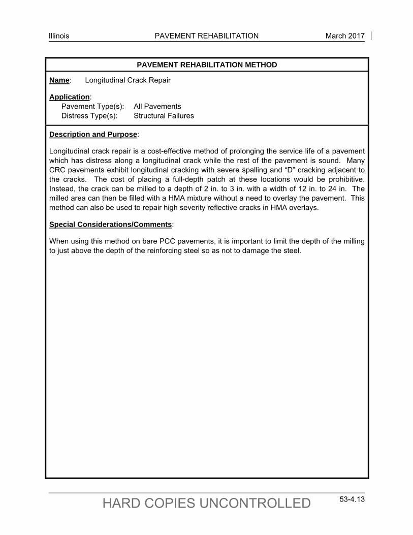
Illinois PAVEMENT REHABILITATION March 2017
53-4.13 HARD COPIES UNCONTROLLED
PAVEMENT REHABILITATION METHOD
Name: Longitudinal Crack Repair
Application: Pavement Type(s): All Pavements Distress Type(s): Structural Failures
Description and Purpose:
Longitudinal crack repair is a cost-effective method of prolonging the service life of a pavement which has distress along a longitudinal crack while the rest of the pavement is sound. Many CRC pavements exhibit longitudinal cracking with severe spalling and “D” cracking adjacent to the cracks. The cost of placing a full-depth patch at these locations would be prohibitive. Instead, the crack can be milled to a depth of 2 in. to 3 in. with a width of 12 in. to 24 in. The milled area can then be filled with a HMA mixture without a need to overlay the pavement. This method can also be used to repair high severity reflective cracks in HMA overlays.
Special Considerations/Comments:
When using this method on bare PCC pavements, it is important to limit the depth of the milling to just above the depth of the reinforcing steel so as not to damage the steel.
Illinois PAVEMENT REHABILITATION March 2017
53-4.14 HARD COPIES UNCONTROLLED
PAVEMENT REHABILITATION METHOD
Name: Underdrains and Longitudinal Edge Drains
Application: Pavement Type(s): All Pavements Distress Type(s): Relates to both Surface Failures and Structural Failures
Description and Purpose:
Subdrainage is an important pavement rehabilitation consideration. Water is a fundamental variable in most problems associated with pavement performance and is directly or indirectly responsible for many pavement distresses. A drainage survey may indicate that underdrains and/or longitudinal edge drains are required to control one or more sources of water in the pavement, thus increasing pavement serviceability and life. Subsurface drainage systems should be designed and constructed with long-term performance and maintenance goals in mind, including periodic inspections to check performance.
Special Considerations/Comments:
The moisture that infiltrates the pavement/shoulder joint usually is the only moisture that can be readily drained. A benefit to installing retrofit longitudinal edge drains is that it will remove the moisture trapped in the slab/base interface. A properly designed and constructed longitudinal edge drain system can, in some cases, improve the long-term load-carrying and distribution properties of the base and subgrade materials. Note that longitudinal edge drains by themselves cannot restore a pavement that is structurally inadequate.
Pavement distress often is accompanied by pumping of the subbase and subgrade material. For this reason, it is important to evaluate the need for underdrain installation. Pipe or drainage mat underdrains will be installed on the Interstate System and other freeway facilities that are designed to Interstate criteria, if they have not been previously installed. Although underdrains are not mandatory on non-Interstate primary facilities, they can be very useful where existing drainage problems exist. Contact the district maintenance personnel for assistance in determining locations where underdrains should be installed. Underdrains should be installed prior to patching unless there are valid reasons to do otherwise.
On rubblizing projects, drainage is very important. An assessment of the existing drains should be made during the design phase, and, if they are not functioning, new underdrains should be installed as the first step in the construction sequence. At the end of the construction sequence, underdrains should be cleaned and flushed out and their functionality ensured.
Illinois PAVEMENT REHABILITATION March 2017
53-4.15 HARD COPIES UNCONTROLLED
PAVEMENT REHABILITATION METHOD
Name: Crack Relief Layers
Application: Pavement Type(s): JPCP/JRCP Pavements, HMA Overlaid JPCP/JRCP Pavements Distress Type(s): Relates to both Surface Failures and Structural Failures
Description and Purpose:
Crack relief layers are used to reduce/retard the amount of reflective cracking in HMA-overlaid JPCP/JRCP pavements. A relatively open-graded aggregate such as CA-7 is mixed with asphalt binder and placed over the deteriorated JPCP/JRCP pavement. HMA binder and surface courses are placed over the crack relief layer. The open-graded nature of the crack relief layer “absorbs” the movement caused by the cracks in the JPCP/JRCP pavement, effectively reducing the stress in HMA binder and surface layers and, thereby, controlling reflective cracking.
Crack relief layers cover over surface defects and cracking, but obvious rocking and pumping patches must be replaced, and base failures patched. Because the crack relief layer may be several inches thick in addition to the standard overlay thickness, this rehabilitation may not be effective in areas with curb and gutter or vertical clearance problems.
Special Considerations/Comments:
Crack relief layers have been used experimentally in Illinois with some success. Approval for use of a crack relief layer must be obtained from the BDE, and an experimental features work plan must be filed with CBM. Contact the Engineer of Technical and Product Studies in the CBM for additional information.
Illinois PAVEMENT REHABILITATION March 2017
53-4.16 HARD COPIES UNCONTROLLED
PAVEMENT REHABILITATION METHOD
Name: Portland Cement Concrete Inlay or Overlay
Application: Pavement Type(s): Hot-Mix Asphalt (HMA) Surfaced Pavements Distress Type(s): Surface Failures
Description and Purpose:
A Portland cement concrete (PCC) inlay or overlay consists of placing 3.0 in. to 6.0 in. of PCC pavement over an existing distressed HMA pavement surface. The existing HMA is first milled to correct profile irregularities and provide a surface for bonding of the inlay or overlay.
A PCC inlay or overlay is suitable for HMA pavements that have a history of rutting and/or shoving. Intersections, with stopping, starting, standing, and turning actions of vehicles, are an example. Other roadways with volumes and types of vehicles that rapidly rut HMA pavements are also good candidates for PCC inlay or overlay.
Special Considerations/Comments:
This rehabilitation strategy is not currently recommended for federal-aid interstates or when the traffic factor exceeds 5.0. Bare concrete or brick areas included in the rehabilitation area should not exceed 5% of the total area. The HMA layer shall be at least 2.50 in. thick. Consider complicated geometrics, utility obstructions, traffic demand, and condition of the existing pavement when selecting this rehabilitation type.
Use of PCC inlays and overlays shall be approved by BDE. Contact the Engineer of Pavement Technology in the CBM for additional information on design.
Illinois PAVEMENT REHABILITATION March 2017
53-4.17 HARD COPIES UNCONTROLLED
PAVEMENT REHABILITATION METHOD
Name: Unbonded Concrete Overlay
Application: Pavement Type(s): PCC Pavements, HMA Overlaid PCC Pavements Distress Type(s): Structural Failures
Description and Purpose:
An unbonded concrete overlay (UCO) consists of an existing concrete pavement, an interlayer, and a PCC overlay. The overlay relies on minimal structural contribution from the existing pavement. Essentially, the two layers function independently. The existing pavement acts as the subbase. The interlayer separates the two pavements. The interlayer retards reflective cracking in the overlay. HMA is an excellent interlayer. The overlay can be JPCP or CRCP. A UCO is an excellent alternative for the structural rehabilitation of deteriorated pavements.
Design inputs include the existing pavement thickness and condition, design life and traffic, subgrade support, and drainage conditions. A preliminary but reasonable estimate of required overlay thickness can be determined by subtracting 1 in from the thickness of a new CRCP calculated using the procedures discussed in Chapter 54. A minimum HMA interlayer thickness of 4 in is recommended.
Special Considerations/Comments:
Consider grade alignment over at-grade structures and vertical clearance between pavement and overhead structures when selecting this rehabilitation method. Long-term planning may be necessary to ensure that structures have sufficient clearance to accommodate a UCO. Due to the increase in pavement grade, side slopes must be modified. This increased slope may require variances from existing policy. Such variances must be approved by the BDE. An additional consideration is how the overlay will be tied to the adjacent pavement or bridge section. Terminal treatments (e.g., lug systems, wide flange beams, special treatments that taper into existing sections) may need to be detailed.
Contact the CBM for assistance in developing UCO designs (i.e., overlay and interlayer thickness requirements, terminal treatments). The suitability of a UCO depends on many factors, and each set of conditions warrants an individualized design. Costs must be considered on a case-by-case basis. Rural sections without overhead structures are ideal locations for UCOs because vertical clearance will not become an issue. Approval for use of UCOs must be obtained from the BDE. Contact the Engineer of Technical and Product Studies in the CBM for additional information.
Illinois PAVEMENT REHABILITATION March 2017
53-4.18 HARD COPIES UNCONTROLLED
PAVEMENT REHABILITATION METHOD
Name: Expansion Joints Application: Pavement Type(s): PCC Pavements, HMA Overlaid PCC Pavements Distress Type(s): Relates to both Surface Failures and Structural Failures
Description and Purpose:
Expansion joints should be visually inspected to determine if they are in working order. If patching is an integral part of the rehabilitation strategy, closed expansion joints should be re-established regardless of the type of patching that is specified.
Special Considerations/Comments:
Consider the following guidelines when re-establishing expansion joints:
1. Jointed Pavements. Consider the following for JPCP and JRCP:
a. Dowelled Patches. Where the pavement requires patching at or near a closed expansion joint, a new joint should be established using a dowelled expansion patch as shown in the Highway Standards for Class B patches. If the joint is closed, but does not require patching, an expansion joint may be formed by sawing the pavement and filling the saw cut with a preformed expansion joint filler material that meets the Standard Specifications for expansion joints.
b. Non-Dowelled Joints. If other than dowelled patches are required and if the pavement is not being resurfaced, a new expansion joint may be formed by sawing the pavement and filling the saw cut with a preformed expansion joint filler material that meets the Standard Specifications.
2. CRC Pavements. If a CRC pavement is being patched with a Class A patch, whether or not the pavement is being resurfaced, existing expansion joints should be re-established using a saw cut filled with preformed expansion joint filler material that meets the Standard Specifications for expansion joints.
Illinois PAVEMENT REHABILITATION March 2017
53-4.19 HARD COPIES UNCONTROLLED
PAVEMENT REHABILITATION METHOD
Name: Lug Areas/Pressure Relief Joints
Application: Pavement Type(s): CRC Pavements, HMA Overlaid CRC Pavements Distress Type(s): Relates to both Surface Failures and Structural Failures
Description and Purpose:
Lug areas that do not show signs of tilting or other similar distresses should not be cut free. If they have previously been cut free and there is no sign of tilting, the continuity of the pavement should be restored through the use of a continuously reinforced patch.
Special Considerations/Comments:
If signs of tilting exist and the pavement surface over the lug area is excessively rough, a 4 in. wide pressure relief joint that is filled with a preformed expansion joint filler material should be provided 150 ft from the lug area. The entire lug system should be subsealed to fill voids, and the area over the lug should be resurfaced to complete the leveling process.
In extreme cases, the lug system should be removed and replaced with a lug system or wide flange beam expansion joint as shown in the Highway Standards.
Illinois PAVEMENT REHABILITATION March 2017
53-4.20 HARD COPIES UNCONTROLLED
PAVEMENT REHABILITATION METHOD
Name: Wide Flange Beam Terminal Joints
Application: Pavement Type(s): CRC Pavements, HMA Overlaid CRC Pavements Distress Type(s): Relates to both Surface Failures and Structural Failures
Description and Purpose:
Existing wide flange beam terminal joints should be closely inspected to determine if the joint is working properly both at the beam and at the expansion joint between the beam and the bridge approach or jointed pavement. In addition, the flange of the beam should be inspected for signs of fatigue cracking.
Special Considerations/Comments:
If the pavement in the area of these joints or the beam itself show signs of distress, special patching details may be required. Contact the BDE for assistance in preparing plans for the proper remedial treatment.
Illinois PAVEMENT REHABILITATION March 2017
53-4.21 HARD COPIES UNCONTROLLED
PAVEMENT REHABILITATION METHOD
Name: Shoulder Rehabilitation
Application: Pavement Type(s): Pavement Shoulders Distress Type(s): Relates to both Surface Failures and Structural Failures
Description and Purpose:
See Section 53-4.06 for information on shoulder rehabilitation methods. HMA mixture design criteria must be met as outlined in Section 53-4.07.
Special Considerations/Comments:
Illinois PAVEMENT REHABILITATION March 2017
53-4.22 HARD COPIES UNCONTROLLED
53-4.02 Guidelines for Selecting Pavement Rehabilitation Strategies
53-4.02(a) Application Matrices for Rehabilitation Methods
Figures 53-4.A through 53-4.D provide guidelines for selecting appropriate rehabilitation methods based on the types of distress exhibited by particular types of pavement. Use these figures to better select rehabilitation methods for the project.
53-4.02(b) Rehabilitation of Bare PCC Pavements
The rehabilitation selection matrices presented in Figure 53-4.E and Figure 53-4.F will assist in the development of rehabilitation alternatives for various conditions of bare PCC pavements. A multiple-bureau district team should be utilized in the decision-making process. These figures are intended to guide the team in developing viable rehabilitation alternatives based on previous knowledge and experience. The following guidelines will apply:
1. Data Collection. It is important to initially determine by a field survey the types of pavement distress being exhibited. This will provide a good indication of the pavement deterioration that can be expected in the future. A second important step is to determine the extent of patching required and the condition of the pavement that is to remain in place. A review of existing records and pavement condition surveys and the implementation of a testing program to further evaluate the condition of the existing pavement structure are essential. See Sections 53-1, 53-2, and 53-3 for additional information on these topics. Use the form presented in Figure 53-4.G to assist in the data collection process. Note that it is not intended that this form become a part of the project report. Rather, it should be used as a guide for data collection and decision making and subsequently saved as background material to support the final decision and to reference for future rehabilitation needs.
2. Surface Condition. Determine the surface condition of the pavement. This includes surface wear, rutting, and polishing.
3. “D” Cracking. Determine where “D” cracking is visible. See Section 53-2 for a description of “D” cracking and associated levels of distress (i.e., Low, Medium, High).
4. New and Existing Patching. Estimate new patching quantities (including replacement of failed existing patches) and determine existing patching quantities. The quantity of existing patching may be obtained from past maintenance and contract records or by a field survey of the existing pavement. Determine whether existing patches are dowelled or tied either by checking previous contracts or by deflection testing. Use the following guidelines to rate new distress:
Low. Less than 0.2% new patching per year. Medium. 0.2% to 0.5% new patching per year. High. Over 0.5% new patching per year.
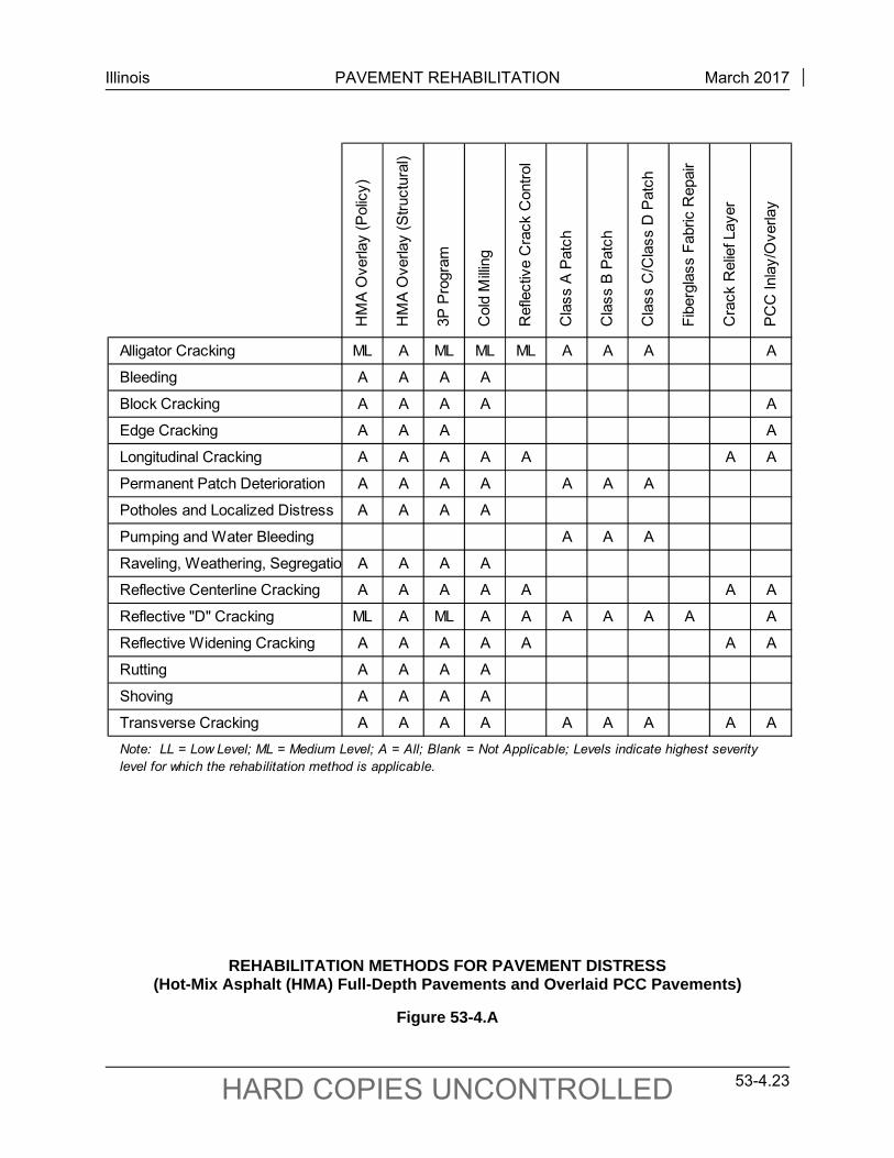
Illinois PAVEMENT REHABILITATION March 2017
53-4.23 HARD COPIES UNCONTROLLED
HM
A O
verla
y (P
olic
y)
HM
A O
verla
y (S
truc
tura
l)
3P
Pro
gram
Col
d M
illin
g
Ref
lect
ive
Cra
ck C
ontr
ol
Cla
ss A
Pat
ch
Cla
ss B
Pat
ch
Cla
ss C
/Cla
ss D
Pat
ch
Fib
ergl
ass
Fab
ric R
epai
r
Cra
ck R
elie
f Lay
er
PC
C In
lay/
Ove
rlay
Alligator Cracking ML A ML ML ML A A A A
Bleeding A A A A
Block Cracking A A A A A
Edge Cracking A A A A
Longitudinal Cracking A A A A A A A
Permanent Patch Deterioration A A A A A A A
Potholes and Localized Distress A A A A
Pumping and Water Bleeding A A A
Raveling, Weathering, Segregatio A A A A
Reflective Centerline Cracking A A A A A A A
Reflective "D" Cracking ML A ML A A A A A A A
Reflective Widening Cracking A A A A A A A
Rutting A A A A
Shoving A A A A
Transverse Cracking A A A A A A A A A
Note: LL = Low Level; ML = Medium Level; A = All; Blank = Not Applicable; Levels indicate highest severity level for which the rehabilitation method is applicable.
REHABILITATION METHODS FOR PAVEMENT DISTRESS (Hot-Mix Asphalt (HMA) Full-Depth Pavements and Overlaid PCC Pavements)
Figure 53-4.A
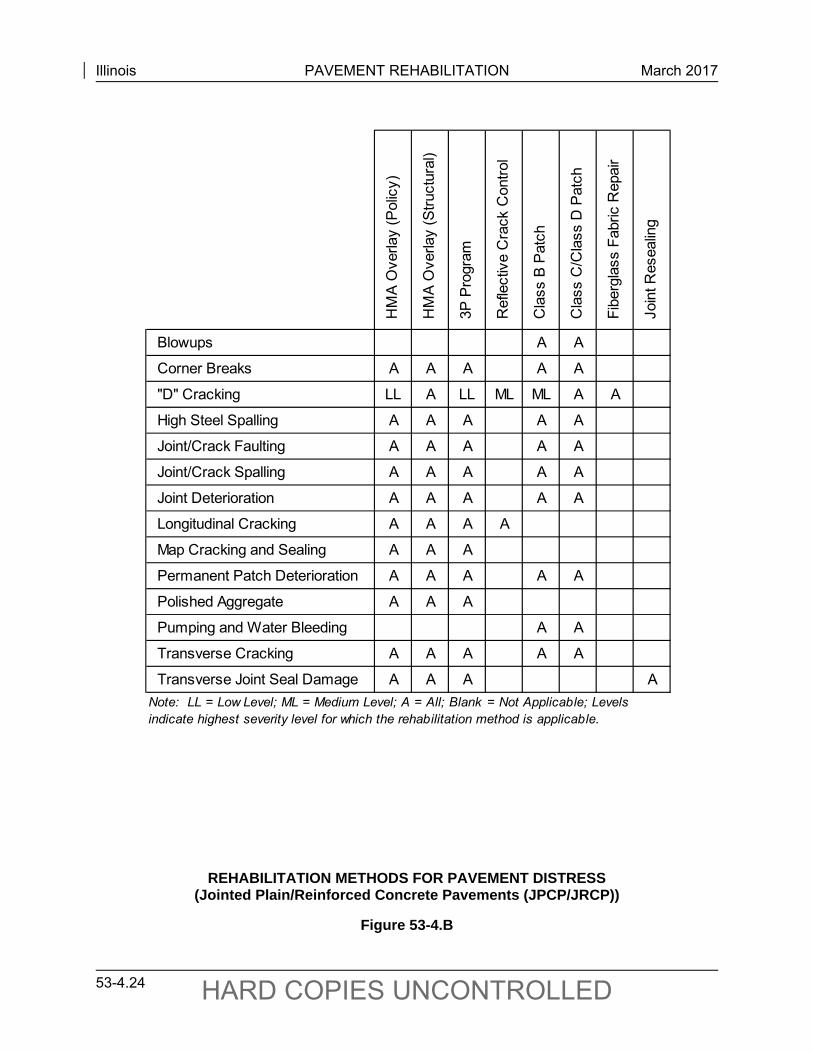
Illinois PAVEMENT REHABILITATION March 2017
53-4.24 HARD COPIES UNCONTROLLED
HM
A O
verla
y (P
olic
y)
HM
A O
verla
y (S
truc
tura
l)
3P
Pro
gram
Ref
lect
ive
Cra
ck C
ontr
ol
Cla
ss B
Pat
ch
Cla
ss C
/Cla
ss D
Pat
ch
Fib
ergl
ass
Fab
ric R
epai
r
Joi
nt R
esea
ling
Blowups A A
Corner Breaks A A A A A
"D" Cracking LL A LL ML ML A A
High Steel Spalling A A A A A
Joint/Crack Faulting A A A A A
Joint/Crack Spalling A A A A A
Joint Deterioration A A A A A
Longitudinal Cracking A A A A
Map Cracking and Sealing A A A
Permanent Patch Deterioration A A A A A
Polished Aggregate A A A
Pumping and Water Bleeding A A
Transverse Cracking A A A A A
Transverse Joint Seal Damage A A A A
Note: LL = Low Level; ML = Medium Level; A = All; Blank = Not Applicable; Levels indicate highest severity level for which the rehabilitation method is applicable.
REHABILITATION METHODS FOR PAVEMENT DISTRESS (Jointed Plain/Reinforced Concrete Pavements (JPCP/JRCP))
Figure 53-4.B
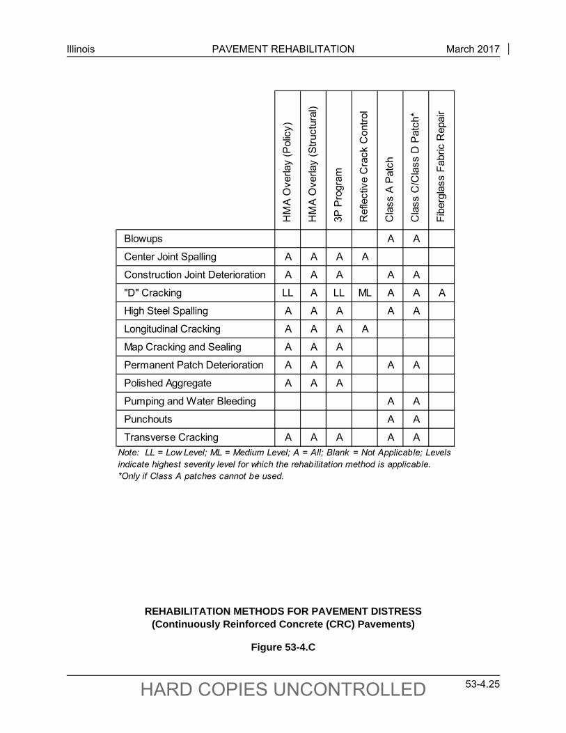
Illinois PAVEMENT REHABILITATION March 2017
53-4.25 HARD COPIES UNCONTROLLED
HM
A O
verla
y (P
olic
y)
HM
A O
verla
y (S
truc
tura
l)
3P
Pro
gram
Ref
lect
ive
Cra
ck C
ontr
ol
Cla
ss A
Pat
ch
Cla
ss C
/Cla
ss D
Pat
ch*
Fib
ergl
ass
Fab
ric R
epai
r
Blowups A A
Center Joint Spalling A A A A
Construction Joint Deterioration A A A A A
"D" Cracking LL A LL ML A A A
High Steel Spalling A A A A A
Longitudinal Cracking A A A A
Map Cracking and Sealing A A A
Permanent Patch Deterioration A A A A A
Polished Aggregate A A A
Pumping and Water Bleeding A A
Punchouts A A
Transverse Cracking A A A A A
Note: LL = Low Level; ML = Medium Level; A = All; Blank = Not Applicable; Levels indicate highest severity level for which the rehabilitation method is applicable. *Only if Class A patches cannot be used.
REHABILITATION METHODS FOR PAVEMENT DISTRESS (Continuously Reinforced Concrete (CRC) Pavements)
Figure 53-4.C
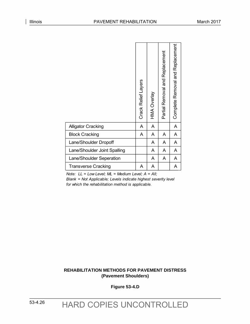
Illinois PAVEMENT REHABILITATION March 2017
53-4.26 HARD COPIES UNCONTROLLED
Cra
ck R
elie
f Lay
ers
HM
A O
verla
y
Par
tial R
emov
al a
nd R
epla
cem
ent
Com
plet
e R
emov
al a
nd R
epla
cem
ent
Alligator Cracking A A A
Block Cracking A A A A
Lane/Shoulder Dropoff A A A
Lane/Shoulder Joint Spalling A A A
Lane/Shoulder Seperation A A A
Transverse Cracking A A A
Note: LL = Low Level; ML = Medium Level; A = All; Blank = Not Applicable; Levels indicate highest severity level for which the rehabilitation method is applicable.
REHABILITATION METHODS FOR PAVEMENT DISTRESS (Pavement Shoulders)
Figure 53-4.D
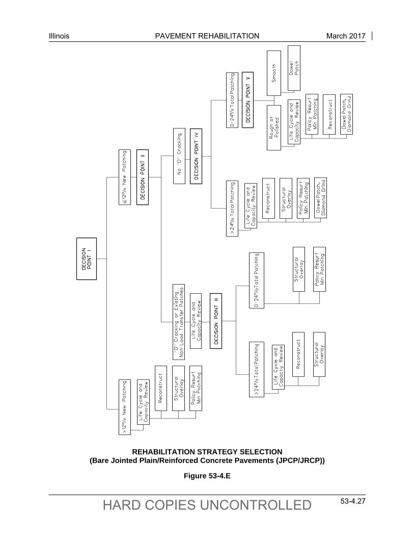
Illinois PAVEMENT REHABILITATION March 2017
53-4.27 HARD COPIES UNCONTROLLED
REHABILITATION STRATEGY SELECTION (Bare Jointed Plain/Reinforced Concrete Pavements (JPCP/JRCP))
Figure 53-4.E
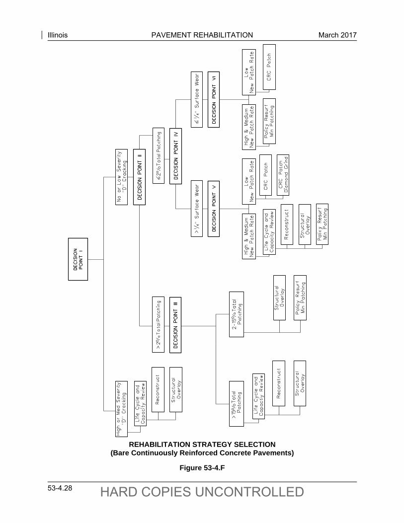
Illinois PAVEMENT REHABILITATION March 2017
53-4.28 HARD COPIES UNCONTROLLED
REHABILITATION STRATEGY SELECTION (Bare Continuously Reinforced Concrete Pavements)
Figure 53-4.F
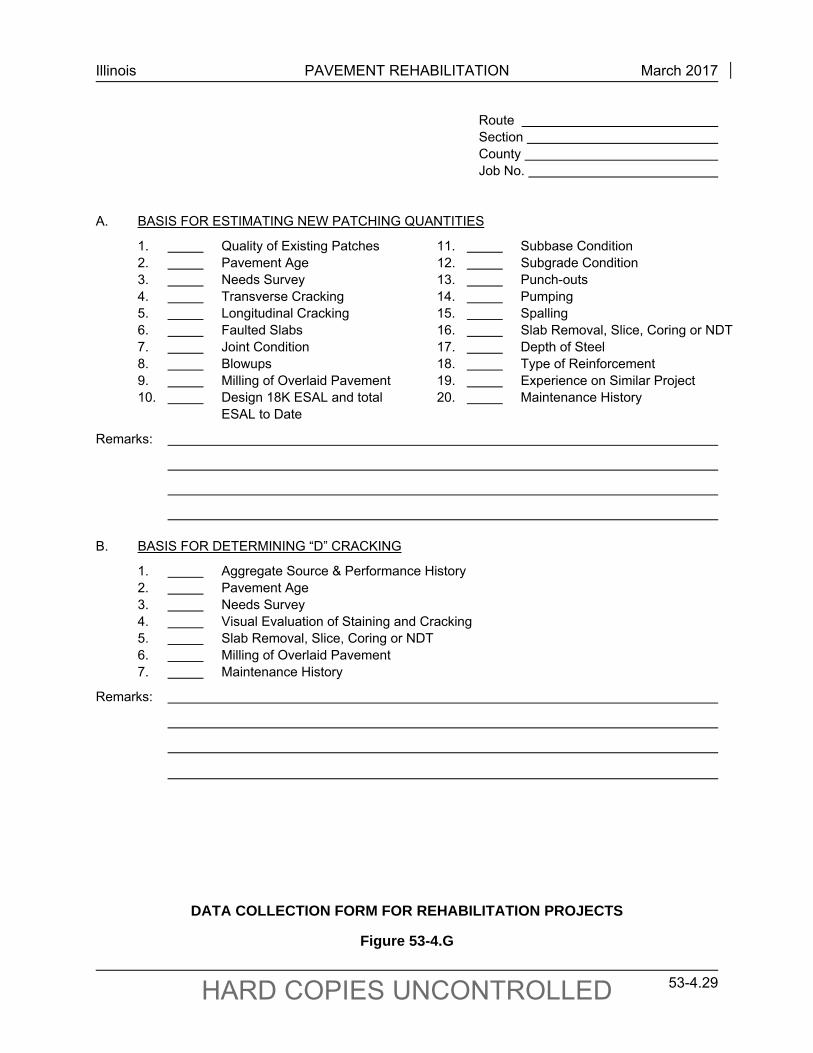
Illinois PAVEMENT REHABILITATION March 2017
53-4.29 HARD COPIES UNCONTROLLED
Route Section County Job No.
A. BASIS FOR ESTIMATING NEW PATCHING QUANTITIES
1. Quality of Existing Patches 11. Subbase Condition 2. Pavement Age 12. Subgrade Condition 3. Needs Survey 13. Punch-outs 4. Transverse Cracking 14. Pumping 5. Longitudinal Cracking 15. Spalling 6. Faulted Slabs 16. Slab Removal, Slice, Coring or NDT 7. Joint Condition 17. Depth of Steel 8. Blowups 18. Type of Reinforcement 9. Milling of Overlaid Pavement 19. Experience on Similar Project 10. Design 18K ESAL and total 20. Maintenance History ESAL to Date
Remarks:
B. BASIS FOR DETERMINING “D” CRACKING
1. Aggregate Source & Performance History 2. Pavement Age 3. Needs Survey 4. Visual Evaluation of Staining and Cracking 5. Slab Removal, Slice, Coring or NDT 6. Milling of Overlaid Pavement 7. Maintenance History
Remarks:
DATA COLLECTION FORM FOR REHABILITATION PROJECTS
Figure 53-4.G
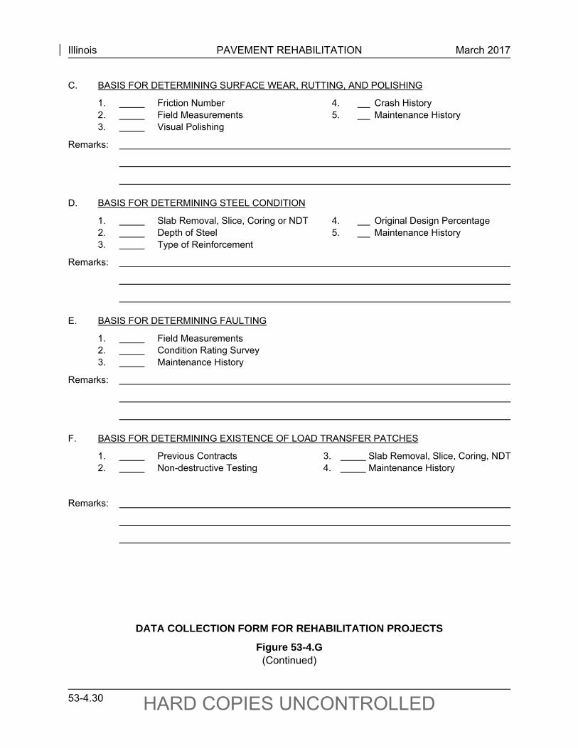
Illinois PAVEMENT REHABILITATION March 2017
53-4.30 HARD COPIES UNCONTROLLED
C. BASIS FOR DETERMINING SURFACE WEAR, RUTTING, AND POLISHING
1. Friction Number 4. Crash History 2. Field Measurements 5. Maintenance History 3. Visual Polishing
Remarks:
D. BASIS FOR DETERMINING STEEL CONDITION
1. Slab Removal, Slice, Coring or NDT 4. Original Design Percentage 2. Depth of Steel 5. Maintenance History 3. Type of Reinforcement
Remarks:
E. BASIS FOR DETERMINING FAULTING
1. Field Measurements 2. Condition Rating Survey 3. Maintenance History
Remarks:
F. BASIS FOR DETERMINING EXISTENCE OF LOAD TRANSFER PATCHES
1. Previous Contracts 3. Slab Removal, Slice, Coring, NDT 2. Non-destructive Testing 4. Maintenance History
Remarks:
DATA COLLECTION FORM FOR REHABILITATION PROJECTS
Figure 53-4.G (Continued)
Illinois PAVEMENT REHABILITATION March 2017
53-4.31 HARD COPIES UNCONTROLLED
5. Total Patching. Determine the total patching quantities. Total patching quantities consist of new patching plus existing patching.
6. Reconstruction. Reconstruction may be in the form of complete removal of the existing pavement and replacement with a new mechanistically designed full-depth flexible or rigid pavement, or it may be in the form of an unbonded concrete overlay or HMA overlay of rubblized PCC having a design consistent with a new full-depth flexible pavement. HMA mixture design criteria must be met as outlined in Section 53-4.07.
7. Structural Overlays. Structural overlays include Unbonded PCC overlays, HMA overlays, and HMA overlays of rubblized PCC that are designed in accordance with the criteria presented in Chapter 54. Unbonded concrete overlays and HMA overlays of rubblized PCC require special design procedures and prior BDE approval. HMA mixture design criteria must be met as outlined in Section 53-4.07.
8. Policy Resurfacing. For a policy resurfacing, use the appropriate thickness guidelines presented in Section 53-4.04. HMA mixture design criteria must be met as outlined in Section 53-4.07.
9. Minimal Patching. Several alternatives may result in a recommendation for minimal patching. Patch only areas showing structural problems (i.e., areas exhibiting pumping or movement or significant loss of materials). Minimal patching may be either full-depth or partial-depth (CRC, dowelled, or HMA) depending on existing pavement condition and previous types of patching. Fiberglass repair system treatment may be used in lieu of patching on CRC pavements with “D” cracking. HMA and undowelled PCC patching only should be used on low-volume or badly deteriorated pavements. Note that drainage should be addressed in areas that exhibit pumping.
10. Life Cycle and Capacity Review. Where reconstruction or a structural overlay are identified as rehabilitation candidates, a review of the pavement’s life cycle (i.e., cost, future distress, user delay problems) and capacity should be conducted to assist in the final selection. See Section 53-5.
11. Other Factors. Other factors that should be considered when making the final selection include ADT, shoulder condition, reinforcement condition, subdrainage condition, traffic control operations, constraints (e.g., bridge clearances, ramps, side slopes), desired life of the rehabilitation, condition of adjacent pavements, and costs.
53-4.02(c) Rehabilitation of HMA Overlaid PCC Pavements
The predominant distresses observed in HMA overlaid PCC pavements are reflective cracking, block cracking, localized distress due to “D” cracking in the PCC, HMA patch deterioration, rutting, stripping, weathering, and raveling. The degree to which these distresses affect the life of the HMA overlay depends on the traffic level, the thickness of the HMA overlay, the quality of the HMA mix, the type of original slab (e.g., JRCP, CRCP), and whether or not the PCC exhibits
Illinois PAVEMENT REHABILITATION March 2017
53-4.32 HARD COPIES UNCONTROLLED
“D” cracking. Project-level evaluation of HMA overlaid PCC pavement rehabilitation should include distress surveying, nondestructive testing, coring, and materials testing.
An HMA overlaid PCC pavement is structurally deficient if it does not have sufficient structural capacity to support the anticipated traffic over its design life. The assessment of a pavement’s structural adequacy must be made within the context of a specific rehabilitation strategy because this will define the point of failure (i.e., if the pavement has a structural deficiency, its rehabilitation must incorporate a structural improvement or the rehabilitation will be short-lived). The rehabilitation strategies for HMA overlaid PCC pavements are as follows:
additional HMA overlay, unbonded concrete overlay, PCC Inlay/Overlay, HMA overlay of rubblized PCC, and reconstruction of one or both traffic lanes.
The decision matrices presented in Figures 53-4.H and 53-4.I will assist in the development of rehabilitation alternatives for various conditions of HMA overlaid PCC pavements. A district multiple-bureau team should be utilized in the decision-making process. These figures are intended to guide the team in developing viable rehabilitation alternatives based on previous knowledge and experience. The following guidelines will apply:
1. Underlying Philosophy. The recommended approach to rehabilitating an HMA overlaid PCC pavement is based on providing the lowest total life-cycle cost over the design period. To the extent practicable, select a rehabilitation strategy that is likely to require future HMA surface rehabilitation but will not require extensive future repair to the underlying layers. The key factor in this approach is the soundness of the existing pavement. The designer must differentiate those candidate pavements that will adequately perform as composite pavements, both now and in the future, from those that will not due to severe deterioration. If the underlying slab is not structurally sound due to either extensively deteriorated transverse cracks or disintegration from “D” cracking, significant repairs and thicker overlays will be required. In such cases, consider other rehabilitation strategies (e.g., HMA overlay of rubblized PCC, unbonded concrete overlay, reconstruction/inlaying).
2. Data Collection. The data collection guidelines presented in Section 53-4.02(b) for rehabilitation of bare PCC pavements also apply to rehabilitation of HMA overlaid pavements.
3. Original PCC Pavement Type. Determine the original PCC pavement from historical data (see Section 53-1). There are significant differences in how an HMA overlay performs on JPCP/JRCP and CRCP, especially those with and without “D” cracking. Thus, somewhat different guidelines are presented in the decision matrices for each pavement type.
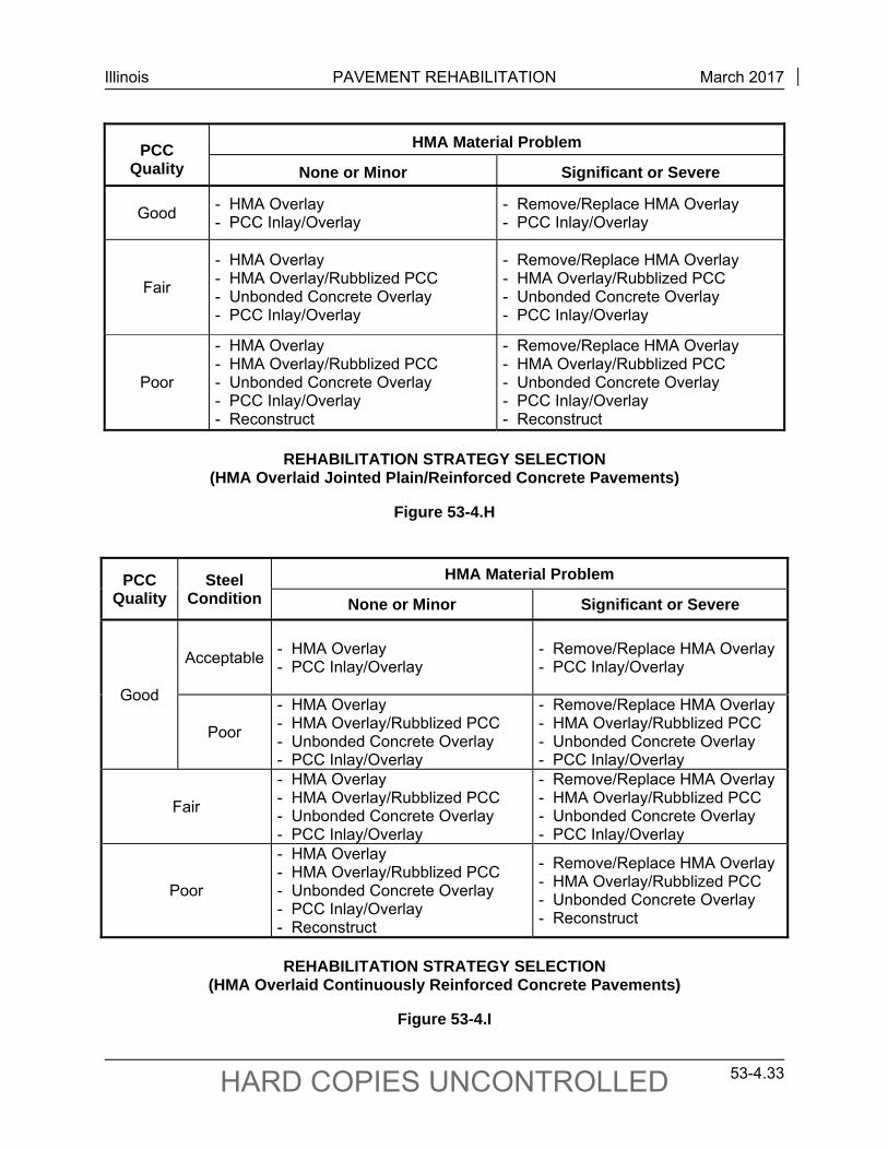
Illinois PAVEMENT REHABILITATION March 2017
53-4.33 HARD COPIES UNCONTROLLED
PCC Quality
HMA Material Problem
None or Minor Significant or Severe
Good - HMA Overlay - PCC Inlay/Overlay
- Remove/Replace HMA Overlay - PCC Inlay/Overlay
Fair
- HMA Overlay - HMA Overlay/Rubblized PCC - Unbonded Concrete Overlay - PCC Inlay/Overlay
- Remove/Replace HMA Overlay - HMA Overlay/Rubblized PCC - Unbonded Concrete Overlay - PCC Inlay/Overlay
Poor
- HMA Overlay - HMA Overlay/Rubblized PCC - Unbonded Concrete Overlay - PCC Inlay/Overlay - Reconstruct
- Remove/Replace HMA Overlay - HMA Overlay/Rubblized PCC - Unbonded Concrete Overlay - PCC Inlay/Overlay - Reconstruct
REHABILITATION STRATEGY SELECTION
(HMA Overlaid Jointed Plain/Reinforced Concrete Pavements)
Figure 53-4.H
PCC Quality
Steel Condition
HMA Material Problem
None or Minor Significant or Severe
Good
Acceptable - HMA Overlay - PCC Inlay/Overlay
- Remove/Replace HMA Overlay - PCC Inlay/Overlay
Poor
- HMA Overlay - HMA Overlay/Rubblized PCC - Unbonded Concrete Overlay - PCC Inlay/Overlay
- Remove/Replace HMA Overlay - HMA Overlay/Rubblized PCC - Unbonded Concrete Overlay - PCC Inlay/Overlay
Fair
- HMA Overlay - HMA Overlay/Rubblized PCC - Unbonded Concrete Overlay - PCC Inlay/Overlay
- Remove/Replace HMA Overlay - HMA Overlay/Rubblized PCC - Unbonded Concrete Overlay - PCC Inlay/Overlay
Poor
- HMA Overlay - HMA Overlay/Rubblized PCC - Unbonded Concrete Overlay - PCC Inlay/Overlay - Reconstruct
- Remove/Replace HMA Overlay - HMA Overlay/Rubblized PCC - Unbonded Concrete Overlay - Reconstruct
REHABILITATION STRATEGY SELECTION
(HMA Overlaid Continuously Reinforced Concrete Pavements)
Figure 53-4.I
Illinois PAVEMENT REHABILITATION March 2017
53-4.34 HARD COPIES UNCONTROLLED
1. PCC Quality. The PCC core condition, “D” cracking, and total repair area are factors that are considered in assigning an overall PCC quality rating (i.e., Good, Fair, Poor). Select the worst rating as the overall PCC quality rating. Consider the following guidelines when making this determination:
a. PCC Core Condition. The condition of cores taken during the field testing process can be used to give a guide to the condition of the PCC pavement. Core condition is rated according to the following:
Good. Core is recovered intact except that a tight vertical crack may be present. Core thickness is equal to or exceeds the design thickness of the pavement. Compressive strengths, if tested, equal or exceeding 3500 psi.
Fair. Core is recovered essentially intact except that a single vertical crack and/or a single horizontal crack may be present. Small hairline cracks may be present. Core thickness is no more than 10 percent less than design thickness. Compressive strengths, if tested, equal or exceed 3000 psi.
Poor. Core is not able to be recovered intact or compressive strengths, if tested, are less than 3000 psi.
b. “D” Cracking Severity. The “D” cracking severity rating is assigned based on the extent and severity of visible distress in the existing HMA overlay reflected from underlying “D” cracking deterioration in the PCC slab (e.g., localized failures, “D” cracked joints and cracks, centerline deterioration). Consider coring in selected areas when determining the extent of “D” cracking. “D” cracking is rated according to the following:
Good. No evidence or knowledge of “D” cracking problems exist; or the PCC slab is known to have “D” cracking, but no “D” cracking distress is visible at the pavement surface. Core samples near joints and cracks are largely intact.
Fair. Some “D” cracking distress is visible on surface of the HMA overlay. Core samples show more than half of the concrete thickness intact.
Poor. Extensive “D” cracking distress is visible on the surface of the HMA overlay. Core samples show less than half of the concrete thickness intact.
c. Total Percent Area of Repair. The rating for the total percent area of repair is based on the sum of the percent area of existing repairs plus the percent area of new repairs needed. Although these quantities will be needed for each traffic lane to estimate total costs for the alternative in an economic analysis, only use
Illinois PAVEMENT REHABILITATION March 2017
53-4.35 HARD COPIES UNCONTROLLED
the outer traffic lane quantities to determine the total percent area of repair for PCC quality rating. Use the following guidelines when making this determination:
Percent Area of Existing Repairs. Although repairs placed after the first overlay will be visible, the percent area of existing repairs is difficult to estimate because such repairs will not be visible unless their joints have reflected through. One option is to conduct a field survey to count the repairs evidenced by reflective cracks and placed after the overlay. This usually is accurate for JPCP/JRCP, however, it is very inaccurate for CRC pavements because many reinforced concrete repairs never develop reflective cracks. A second option is to search historical maintenance and contract records to determine the quantity of repairs placed since original construction.
Percent Area of New Repairs Needed. Determine the number of deteriorated reflective cracks and localized failures and prorate the result in number per mile. The percent area of required new full-depth repairs is computed by multiplying the number of repair locations by the mean area per repair (e.g., 72 ft2 for a typical repair size of 6 ft by 12 ft), dividing the lane area per mile (e.g., 63,360 ft2 which equals 12 ft by 5,280 ft), and multiplying by 100.
Non-Load Transfer/Disintegrated Repairs. If a second HMA overlay is planned, existing PCC repairs that are not reinforced in CRC pavements or dowelled in JPCP/JRCP should ideally be replaced and, therefore, should be counted as new repairs needed. Full-depth HMA patches and undowelled or unreinforced PCC repairs have poor load transfer and will cause rapid propagation and deterioration of reflective cracks in the HMA overlay. Consult maintenance records to determine if existing PCC repairs have dowels or reinforcement. Count any new repairs needed to replace existing deteriorated repairs once as new repairs. Do not duplicate their quantity when adding new and existing repair quantities. Count HMA patches and deteriorated repairs as new repairs rather than existing repairs because, unless these repairs are replaced, any new HMA overlay will need to be thicker to compensate for the affect that reflective cracking will have on performance. The number of needed new repairs which are not placed is a factor in the second HMA overlay thickness design.
Quality Rating. Use Figure 53-4.J to rate total percent area of repair.
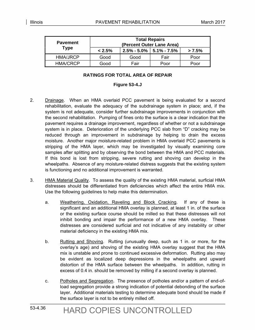
Illinois PAVEMENT REHABILITATION March 2017
53-4.36 HARD COPIES UNCONTROLLED
Pavement Type
Total Repairs (Percent Outer Lane Area)
< 2.5% 2.5% - 5.0% 5.1% - 7.5% > 7.5% HMA/JRCP Good Good Fair Poor HMA/CRCP Good Fair Poor Poor
RATINGS FOR TOTAL AREA OF REPAIR
Figure 53-4.J
2. Drainage. When an HMA overlaid PCC pavement is being evaluated for a second
rehabilitation, evaluate the adequacy of the subdrainage system in place; and, if the system is not adequate, consider further subdrainage improvements in conjunction with the second rehabilitation. Pumping of fines onto the surface is a clear indication that the pavement requires a drainage improvement, regardless of whether or not a subdrainage system is in place. Deterioration of the underlying PCC slab from “D” cracking may be reduced through an improvement in subdrainage by helping to drain the excess moisture. Another major moisture-related problem in HMA overlaid PCC pavements is stripping of the HMA layer, which may be investigated by visually examining core samples after splitting and by observing the bond between the HMA and PCC materials. If this bond is lost from stripping, severe rutting and shoving can develop in the wheelpaths. Absence of any moisture-related distress suggests that the existing system is functioning and no additional improvement is warranted.
3. HMA Material Quality. To assess the quality of the existing HMA material, surficial HMA distresses should be differentiated from deficiencies which affect the entire HMA mix. Use the following guidelines to help make this determination.
a. Weathering, Oxidation, Raveling and Block Cracking. If any of these is significant and an additional HMA overlay is planned, at least 1 in. of the surface or the existing surface course should be milled so that these distresses will not inhibit bonding and impair the performance of a new HMA overlay. These distresses are considered surficial and not indicative of any instability or other material deficiency in the existing HMA mix.
b. Rutting and Shoving. Rutting (unusually deep, such as 1 in. or more, for the overlay’s age) and shoving of the existing HMA overlay suggest that the HMA mix is unstable and prone to continued excessive deformation. Rutting also may be evident as localized deep depressions in the wheelpaths and upward distortion of the HMA surface between the wheelpaths. In addition, rutting in excess of 0.4 in. should be removed by milling if a second overlay is planned.
c. Potholes and Segregation. The presence of potholes and/or a pattern of end-of-load segregation provide a strong indication of potential debonding of the surface layer. Additional materials testing to determine adequate bond should be made if the surface layer is not to be entirely milled off.
Illinois PAVEMENT REHABILITATION March 2017
53-4.37 HARD COPIES UNCONTROLLED
d. Reflective Cracking. Reflective cracking of underlying JPCP/JRCP joints, cracks, and patches can significantly impact the ride quality of an HMA overlay. Thinner overlays are quickly cracked, and the ride, as measured by IRI, will become rougher. For those pavements with premature failure of the first generation HMA overlay due to severe faulting or rocking of the underlying slabs, consideration should be given to an unbonded concrete overlay, HMA overlay of rubblized PCC, or complete reconstruction.
e. Bleeding. Bleeding of excess asphalt binder to the pavement surface represents a material degradation due to mixture composition or construction. These areas are prone to rutting, shoving, and a loss of surface texture. Excessive areas of bleeding may indicate the presence of stripping in the HMA mixture.
f. Tensile Strength. Tensile strength values provide a strong indication of material degradation. Consideration should be given to remove layers with poor tensile strength before placing a subsequent overlay.
g. Stripping. Stripping (i.e., loss of bond between the asphalt binder and the aggregate in the mix), represents diminished structural capacity of the HMA surface. This distress indicates a material deficiency that affects the full thickness of the HMA overlay. If a second HMA overlay is planned and this distress is significant in the existing HMA, give serious consideration to complete removal of the existing HMA overlay prior to placement of any new overlay. Loss of bond between the HMA overlay and the concrete slab also may result from stripping. If this has occurred, the entire HMA overlay should be removed.
4. Steel Condition in CRCP. In some CRC pavements, the steel reinforcement may have corroded to the extent that many wide cracks have developed that eventually will rupture and need to be repaired. The steel’s condition may be examined by coring through cracks at positions where longitudinal bars are located. The following definitions apply to typical transverse cracks that have developed in CRCP, and not to cracks that have already opened because of steel rupture.
a. Acceptable. Bar condition at transverse cracks varies from “free of corrosion” (almost new condition) to “heavy corrosion with pitting” (no significant cross-sectional area lost).
b. Poor. Bar condition at transverse cracks exhibits advanced corrosion accompanied by a marked reduction in cross-sectional area (necking down). If 10% or more of the bar samples are rated as “Poor,” the overall steel condition should be rated as “Poor.”
5. Other Factors. Other factors that should be considered in developing a complete rehabilitation strategy include adequacy of existing subdrainage, shoulder condition, traffic control options, geometric constraints (e.g., ramps, side slopes, right-of-way, overhead clearances), and the desired design life of the rehabilitation.
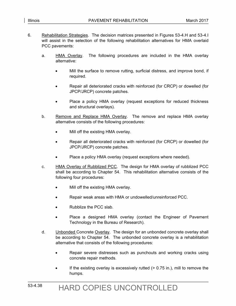
Illinois PAVEMENT REHABILITATION March 2017
53-4.38 HARD COPIES UNCONTROLLED
6. Rehabilitation Strategies. The decision matrices presented in Figures 53-4.H and 53-4.I will assist in the selection of the following rehabilitation alternatives for HMA overlaid PCC pavements:
a. HMA Overlay. The following procedures are included in the HMA overlay alternative:
Mill the surface to remove rutting, surficial distress, and improve bond, if required.
Repair all deteriorated cracks with reinforced (for CRCP) or dowelled (for JPCP/JRCP) concrete patches.
Place a policy HMA overlay (request exceptions for reduced thickness and structural overlays).
b. Remove and Replace HMA Overlay. The remove and replace HMA overlay alternative consists of the following procedures:
Mill off the existing HMA overlay.
Repair all deteriorated cracks with reinforced (for CRCP) or dowelled (for JPCP/JRCP) concrete patches.
Place a policy HMA overlay (request exceptions where needed).
c. HMA Overlay of Rubblized PCC. The design for HMA overlay of rubblized PCC shall be according to Chapter 54. This rehabilitation alternative consists of the following four procedures:
Mill off the existing HMA overlay.
Repair weak areas with HMA or undowelled/unreinforced PCC.
Rubblize the PCC slab.
Place a designed HMA overlay (contact the Engineer of Pavement Technology in the Bureau of Research).
d. Unbonded Concrete Overlay. The design for an unbonded concrete overlay shall be according to Chapter 54. The unbonded concrete overlay is a rehabilitation alternative that consists of the following procedures:
Repair severe distresses such as punchouts and working cracks using concrete repair methods.
If the existing overlay is excessively rutted (> 0.75 in.), mill to remove the humps.
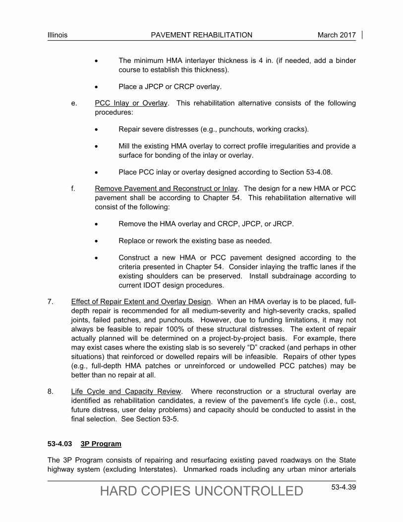
Illinois PAVEMENT REHABILITATION March 2017
53-4.39 HARD COPIES UNCONTROLLED
The minimum HMA interlayer thickness is 4 in. (if needed, add a binder course to establish this thickness).
Place a JPCP or CRCP overlay.
e. PCC Inlay or Overlay. This rehabilitation alternative consists of the following procedures:
Repair severe distresses (e.g., punchouts, working cracks).
Mill the existing HMA overlay to correct profile irregularities and provide a surface for bonding of the inlay or overlay.
Place PCC inlay or overlay designed according to Section 53-4.08.
f. Remove Pavement and Reconstruct or Inlay. The design for a new HMA or PCC pavement shall be according to Chapter 54. This rehabilitation alternative will consist of the following:
Remove the HMA overlay and CRCP, JPCP, or JRCP.
Replace or rework the existing base as needed.
Construct a new HMA or PCC pavement designed according to the criteria presented in Chapter 54. Consider inlaying the traffic lanes if the existing shoulders can be preserved. Install subdrainage according to current IDOT design procedures.
7. Effect of Repair Extent and Overlay Design. When an HMA overlay is to be placed, full-depth repair is recommended for all medium-severity and high-severity cracks, spalled joints, failed patches, and punchouts. However, due to funding limitations, it may not always be feasible to repair 100% of these structural distresses. The extent of repair actually planned will be determined on a project-by-project basis. For example, there may exist cases where the existing slab is so severely “D” cracked (and perhaps in other situations) that reinforced or dowelled repairs will be infeasible. Repairs of other types (e.g., full-depth HMA patches or unreinforced or undowelled PCC patches) may be better than no repair at all.
8. Life Cycle and Capacity Review. Where reconstruction or a structural overlay are identified as rehabilitation candidates, a review of the pavement’s life cycle (i.e., cost, future distress, user delay problems) and capacity should be conducted to assist in the final selection. See Section 53-5.
53-4.03 3P Program
The 3P Program consists of repairing and resurfacing existing paved roadways on the State highway system (excluding Interstates). Unmarked roads including any urban minor arterials
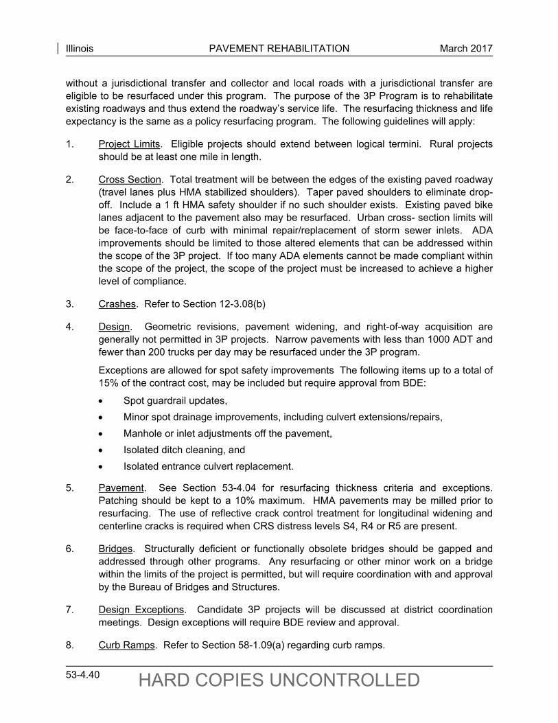
Illinois PAVEMENT REHABILITATION March 2017
53-4.40 HARD COPIES UNCONTROLLED
without a jurisdictional transfer and collector and local roads with a jurisdictional transfer are eligible to be resurfaced under this program. The purpose of the 3P Program is to rehabilitate existing roadways and thus extend the roadway’s service life. The resurfacing thickness and life expectancy is the same as a policy resurfacing program. The following guidelines will apply:
1. Project Limits. Eligible projects should extend between logical termini. Rural projects should be at least one mile in length.
2. Cross Section. Total treatment will be between the edges of the existing paved roadway (travel lanes plus HMA stabilized shoulders). Taper paved shoulders to eliminate drop-off. Include a 1 ft HMA safety shoulder if no such shoulder exists. Existing paved bike lanes adjacent to the pavement also may be resurfaced. Urban cross- section limits will be face-to-face of curb with minimal repair/replacement of storm sewer inlets. ADA improvements should be limited to those altered elements that can be addressed within the scope of the 3P project. If too many ADA elements cannot be made compliant within the scope of the project, the scope of the project must be increased to achieve a higher level of compliance.
3. Crashes. Refer to Section 12-3.08(b)
4. Design. Geometric revisions, pavement widening, and right-of-way acquisition are generally not permitted in 3P projects. Narrow pavements with less than 1000 ADT and fewer than 200 trucks per day may be resurfaced under the 3P program.
Exceptions are allowed for spot safety improvements The following items up to a total of 15% of the contract cost, may be included but require approval from BDE:
Spot guardrail updates,
Minor spot drainage improvements, including culvert extensions/repairs,
Manhole or inlet adjustments off the pavement,
Isolated ditch cleaning, and
Isolated entrance culvert replacement.
5. Pavement. See Section 53-4.04 for resurfacing thickness criteria and exceptions. Patching should be kept to a 10% maximum. HMA pavements may be milled prior to resurfacing. The use of reflective crack control treatment for longitudinal widening and centerline cracks is required when CRS distress levels S4, R4 or R5 are present.
6. Bridges. Structurally deficient or functionally obsolete bridges should be gapped and addressed through other programs. Any resurfacing or other minor work on a bridge within the limits of the project is permitted, but will require coordination with and approval by the Bureau of Bridges and Structures.
7. Design Exceptions. Candidate 3P projects will be discussed at district coordination meetings. Design exceptions will require BDE review and approval.
8. Curb Ramps. Refer to Section 58-1.09(a) regarding curb ramps.
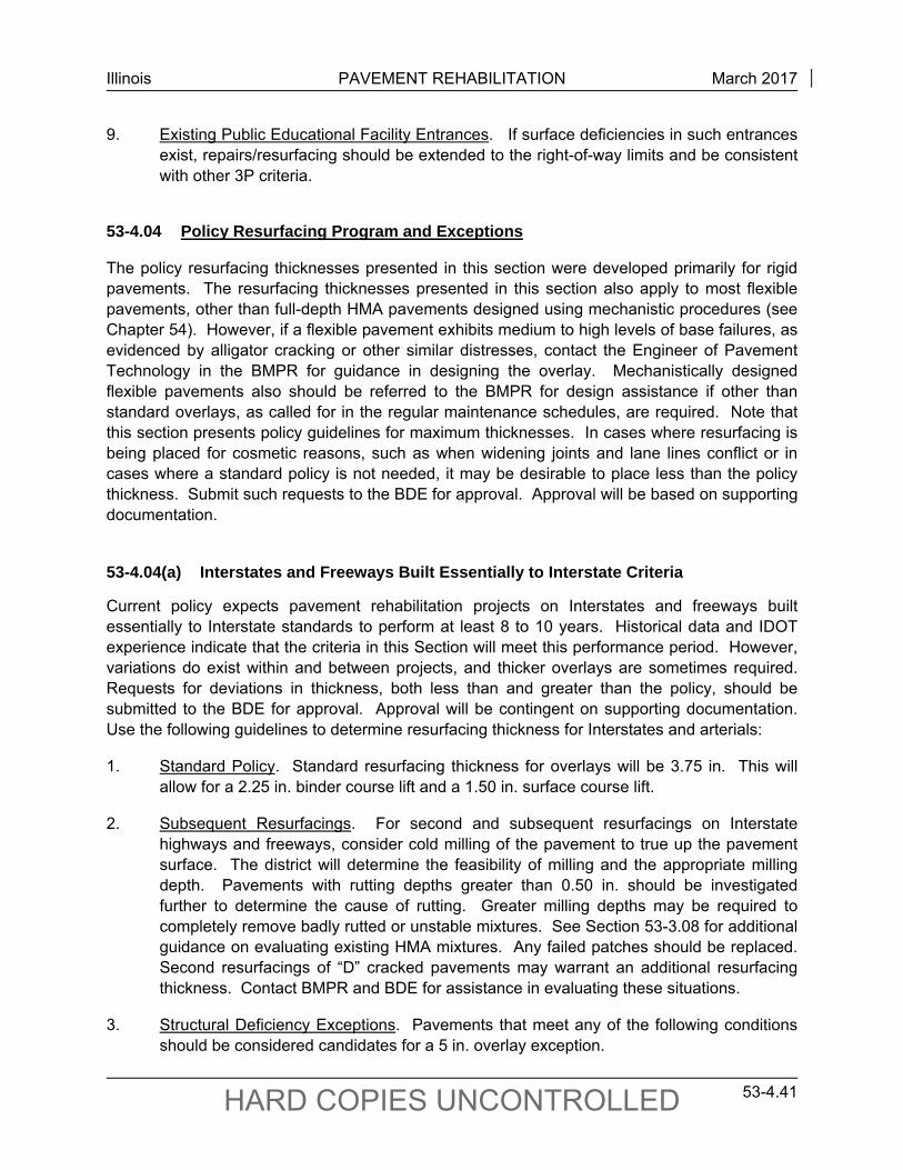
Illinois PAVEMENT REHABILITATION March 2017
53-4.41 HARD COPIES UNCONTROLLED
9. Existing Public Educational Facility Entrances. If surface deficiencies in such entrances exist, repairs/resurfacing should be extended to the right-of-way limits and be consistent with other 3P criteria.
53-4.04 Policy Resurfacing Program and Exceptions
The policy resurfacing thicknesses presented in this section were developed primarily for rigid pavements. The resurfacing thicknesses presented in this section also apply to most flexible pavements, other than full-depth HMA pavements designed using mechanistic procedures (see Chapter 54). However, if a flexible pavement exhibits medium to high levels of base failures, as evidenced by alligator cracking or other similar distresses, contact the Engineer of Pavement Technology in the BMPR for guidance in designing the overlay. Mechanistically designed flexible pavements also should be referred to the BMPR for design assistance if other than standard overlays, as called for in the regular maintenance schedules, are required. Note that this section presents policy guidelines for maximum thicknesses. In cases where resurfacing is being placed for cosmetic reasons, such as when widening joints and lane lines conflict or in cases where a standard policy is not needed, it may be desirable to place less than the policy thickness. Submit such requests to the BDE for approval. Approval will be based on supporting documentation.
53-4.04(a) Interstates and Freeways Built Essentially to Interstate Criteria
Current policy expects pavement rehabilitation projects on Interstates and freeways built essentially to Interstate standards to perform at least 8 to 10 years. Historical data and IDOT experience indicate that the criteria in this Section will meet this performance period. However, variations do exist within and between projects, and thicker overlays are sometimes required. Requests for deviations in thickness, both less than and greater than the policy, should be submitted to the BDE for approval. Approval will be contingent on supporting documentation. Use the following guidelines to determine resurfacing thickness for Interstates and arterials:
1. Standard Policy. Standard resurfacing thickness for overlays will be 3.75 in. This will allow for a 2.25 in. binder course lift and a 1.50 in. surface course lift.
2. Subsequent Resurfacings. For second and subsequent resurfacings on Interstate highways and freeways, consider cold milling of the pavement to true up the pavement surface. The district will determine the feasibility of milling and the appropriate milling depth. Pavements with rutting depths greater than 0.50 in. should be investigated further to determine the cause of rutting. Greater milling depths may be required to completely remove badly rutted or unstable mixtures. See Section 53-3.08 for additional guidance on evaluating existing HMA mixtures. Any failed patches should be replaced. Second resurfacings of “D” cracked pavements may warrant an additional resurfacing thickness. Contact BMPR and BDE for assistance in evaluating these situations.
3. Structural Deficiency Exceptions. Pavements that meet any of the following conditions should be considered candidates for a 5 in. overlay exception.
Illinois PAVEMENT REHABILITATION March 2017
53-4.42 HARD COPIES UNCONTROLLED
JPCP/JRCP with medium to high levels of “D” cracking over at least 30% of the project and CRC pavements that exhibit low to medium levels of “D” cracking over at least 30% of the project;
JPCP/JRCP and CRCP with excessive total patching quantities which can be reduced by the additional overlay thickness;
JPCP/JRCP with average faulting in excess of 0.50 in. (faults in excess of 0.75 in. should be patched); and/or
JPCP/JRCP and CRCP with current traffic levels in excess of 7,500 heavy commercial units per day.
4. Surface Mixture Exceptions. Use of SMA mixtures may be appropriate on certain high volume routes. Districts may request a thickness variance in order to use SMA mixtures. No additional project funding will be granted for the use of SMA mixtures.
53-4.04(b) Other State Maintained Highways
Current policy expects pavement rehabilitation projects on other State maintained highways to perform for least 8 years. Historical data and IDOT experience indicate that, for the majority of previously resurfaced pavements, a 2.25 in. overlay will exceed the required performance period. Cold milling to remove rutting and similar pavement distresses also should be considered. Variations do exist within and between projects, and thicker overlays are sometimes required. Requests for deviations in thickness, both less than and greater than the policy should be submitted to the BDE for approval. Approval will be contingent on supporting documentation. Use the following guidelines to determine resurfacing thickness for other State maintained highways:
1. Standard Policy. Standard resurfacing thickness calls for a 2.25 in. overlay. On those highways where the existing concrete has not been resurfaced, or where widening is being placed, the standard overlay thickness should be increased to 2.50 in. Projects should be designed to these criteria, unless an exception can be justified.
2. Exception 1 Jurisdictional Transfer. Requests for additional resurfacing thickness will be approved only if the transfer is approved by the accepting agency. The amount of additional thickness should be held to the minimum that will allow the transfer to be accomplished. A field review conducted by the Pavement Review Team may be required for projects that include unusual or experimental treatments.
3. Exception 2 Consistency. Projects that border on new or reconstructed sections with 15 year or greater design periods may qualify for additional thickness. Design the overlay for the same design period using the composite pavement design method that is presented in Chapter 54. Projects that contain an urban cross section with new curb and gutter also may qualify for additional thickness. Design the overlay for a 15-year design period using the composite pavement design method. Ensure that design
Illinois PAVEMENT REHABILITATION March 2017
53-4.43 HARD COPIES UNCONTROLLED
calculations accompany any request to the BDE. Figure 53-4.K presents coefficients (based on average conditions) that may be used to evaluate new and old pavement materials at various periods to determining the thickness of the structural overlay required.
4. Exception 3 Profile Corrections. Current policy requires a cross slope of 1.5% for new construction to promote cross drainage and prevent the ponding of water on the pavement surface. Most existing pavements constructed with circular crowns contain adequate cross slope to achieve this objective. For this reason, crown correction normally will not be required in resurfacing contracts. Where, due to uneven settlement or other reasons, a minimum cross slope of 1% is not available, first consider cold milling to obtain the proper crown. If cold milling is not feasible, prepare plans for crown correction using a 1.5% cross slope for the required resurfacing thickness.
5. Exception 4 Structural Deficiency. The following pavements may qualify for a 3.75 in. overlay:
pavements with severe base failures;
JPCP/JRCP and CRCP with excessive total patching quantities that can be reduced by the additional overlay thickness;
JPCP/JRCP with average faulting in excess of 0.50 in.;
JPCP/JRCP, CRCP, and overlaid PCC pavements exhibiting “D” cracking; and
pavements with a current CRS rating of 3.9 and less.
6. Exception 5 Heavy Traffic. Class I, II, and III primary highways with heavy traffic that have not been previously resurfaced will be eligible for additional resurfacing thickness as shown in Figure 53-4.L. The current ADT will be used for eligibility determination and should be submitted with the request. First and subsequent resurfacing projects for which substantial increases in traffic are expected (as in the case of detours), and projects for which commercial traffic travels fully loaded in one direction and empty in the other will be considered special cases and will be referred to the BDE and BMPR for analysis.
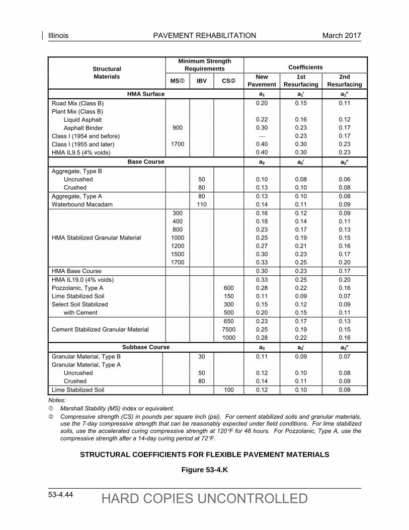
Illinois PAVEMENT REHABILITATION March 2017
53-4.44 HARD COPIES UNCONTROLLED
Structural Materials
Minimum Strength Requirements Coefficients
MS IBV CS NewPavement
1st Resurfacing
2nd Resurfacing
HMA Surface a1 a1 a1
Road Mix (Class B) 0.20 0.15 0.11
Plant Mix (Class B)
Liquid Asphalt 0.22 0.16 0.12
Asphalt Binder 900 0.30 0.23 0.17
Class I (1954 and before) 0.23 0.17
Class I (1955 and later) 1700 0.40 0.30 0.23
HMA IL9.5 (4% voids) 0.40 0.30 0.23
Base Course a2 a2 a2
Aggregate, Type B Uncrushed 50 0.10 0.08 0.06 Crushed 80 0.13 0.10 0.08
Aggregate, Type A 80 0.13 0.10 0.08 Waterbound Macadam 110 0.14 0.11 0.09
HMA Stabilized Granular Material
300 0.16 0.12 0.09 400 0.18 0.14 0.11 800 0.23 0.17 0.13
1000 0.25 0.19 0.15 1200 0.27 0.21 0.16 1500 0.30 0.23 0.17 1700 0.33 0.25 0.20
HMA Base Course 0.30 0.23 0.17
HMA IL19.0 (4% voids) 0.33 0.25 0.20 Pozzolanic, Type A 600 0.28 0.22 0.16 Lime Stabilized Soil 150 0.11 0.09 0.07 Select Soil Stabilized 300 0.15 0.12 0.09 with Cement 500 0.20 0.15 0.11
Cement Stabilized Granular Material 650 0.23 0.17 0.13 7500 0.25 0.19 0.15 1000 0.28 0.22 0.16
Subbase Course a3 a3 a3 Granular Material, Type B 30 0.11 0.09 0.07 Granular Material, Type A Uncrushed 50 0.12 0.10 0.08 Crushed 80 0.14 0.11 0.09
Lime Stabilized Soil 100 0.12 0.10 0.08
Notes: Marshall Stability (MS) index or equivalent. Compressive strength (CS) in pounds per square inch (psi). For cement stabilized soils and granular materials,
use the 7-day compressive strength that can be reasonably expected under field conditions. For lime stabilized soils, use the accelerated curing compressive strength at 120F for 48 hours. For Pozzolanic, Type A, use the compressive strength after a 14-day curing period at 72F.
STRUCTURAL COEFFICIENTS FOR FLEXIBLE PAVEMENT MATERIALS
Figure 53-4.K
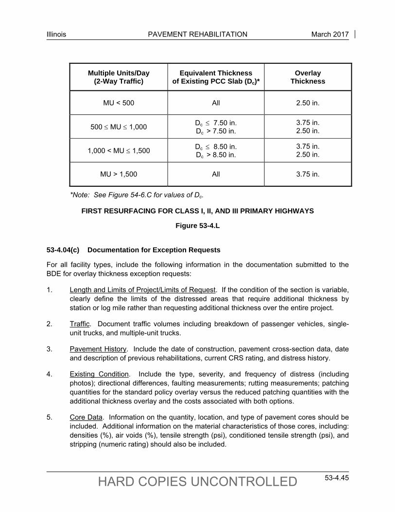
Illinois PAVEMENT REHABILITATION March 2017
53-4.45 HARD COPIES UNCONTROLLED
Multiple Units/Day (2-Way Traffic)
Equivalent Thickness of Existing PCC Slab (Dc)*
Overlay Thickness
MU < 500 All 2.50 in.
500 MU 1,000 Dc 7.50 in. Dc > 7.50 in.
3.75 in. 2.50 in.
1,000 < MU 1,500 Dc 8.50 in. Dc > 8.50 in.
3.75 in. 2.50 in.
MU > 1,500 All 3.75 in.
*Note: See Figure 54-6.C for values of Dc.
FIRST RESURFACING FOR CLASS I, II, AND III PRIMARY HIGHWAYS
Figure 53-4.L
53-4.04(c) Documentation for Exception Requests
For all facility types, include the following information in the documentation submitted to the BDE for overlay thickness exception requests:
1. Length and Limits of Project/Limits of Request. If the condition of the section is variable, clearly define the limits of the distressed areas that require additional thickness by station or log mile rather than requesting additional thickness over the entire project.
2. Traffic. Document traffic volumes including breakdown of passenger vehicles, single-unit trucks, and multiple-unit trucks.
3. Pavement History. Include the date of construction, pavement cross-section data, date and description of previous rehabilitations, current CRS rating, and distress history.
4. Existing Condition. Include the type, severity, and frequency of distress (including photos); directional differences, faulting measurements; rutting measurements; patching quantities for the standard policy overlay versus the reduced patching quantities with the additional thickness overlay and the costs associated with both options.
5. Core Data. Information on the quantity, location, and type of pavement cores should be included. Additional information on the material characteristics of those cores, including: densities (%), air voids (%), tensile strength (psi), conditioned tensile strength (psi), and stripping (numeric rating) should also be included.
Illinois PAVEMENT REHABILITATION March 2017
53-4.46 HARD COPIES UNCONTROLLED
6. Calculations and Estimates. Include all relevant supporting calculations and cost estimates.
7. Other. Include any other supporting evidence and test data and photographs.
Usually, the required documentation can be contained in a simple memo that will not require extensive work on the part of the designer. Based on the content of the submittal, the total length of the project, and the percent of the project for which additional or reduced overlay thickness is requested, a joint field review with the district and the Pavement Review Team (PRT) may be warranted.
The PRT consists of members from the BDE, BMPR, and OPP as well as the district. The PRT serves a vital role in the selection of appropriate and cost-effective rehabilitation strategies for individual projects and assists in identifying and prioritizing rehabilitation strategies that provide long-lasting, high-quality rehabilitations without compromising the overall quality of the highway network. Additionally, the PRT is responsible for conducting Statewide reviews of all Interstates.
In many cases, a joint field trip with the PRT will not be necessary if the exception request is of a standard nature or involves minor deviations. It is often possible for the PRT to review the pavement section using the CRS video logging database. To facilitate such reviews, include the Tape Set Number and Frame Reference in the request. If the request is properly documented in such cases, the PRT may grant the exception without a need for additional action.
53-4.04(d) Waterproofing and Surfacing of Bridge Decks
It is extremely difficult to obtain the desired density in the HMA surface course for lift thickness less than 1.75 in. because 0.50 in. of the overlay thickness will be reserved for the waterproofing membrane system (i.e., membrane plus sand asphalt protection layer). This would result in a thin lift of HMA surface course remaining which cannot be compacted to the required density. The minimum HMA surface course thickness that can be adequately compacted is 1.25 in. for an IL-9.5 mixture. Therefore, for all projects on which plans are developed for waterproofing and surfacing bridge decks, specify a minimum 1.75 in. thick overlay for an IL-9.5 mixture to adequately accommodate both the waterproofing membrane system and the HMA surface course.
53-4.04(e) Resurfacing of Stabilized Shoulders
Stabilized shoulders should be resurfaced in conjunction with pavement resurfacing. The following guidelines apply:
1. Rehabilitation. Survey existing stabilized shoulders to determine their condition and the type and amount of work necessary to properly repair the base. Specify shoulder resurfacing to the nominal thickness of the resurfaced pavement. Guidelines for shoulder rehabilitation are presented in Section 53-4.06.
Illinois PAVEMENT REHABILITATION March 2017
53-4.47 HARD COPIES UNCONTROLLED
2. Cross Section. For Interstate highways, the width of shoulder stabilization should equal the nominal width of the existing stabilized shoulder, except that in no case will the resurfaced shoulder width be less than 10 ft right and 4 ft left. However, where the existing stabilized shoulder also is current design width for new construction, the top width of the resurfacing may be reduced at the rate of 1 in. for each 1 in. of resurfacing thickness. The shoulder cross slope may be increased from 4% to a maximum of 6%, except where adjacent to superelevated pavements where the high side shoulder should be sloped so that the algebraic difference between the pavement and shoulder slopes does not exceed 8%. Make spot checks of the elevation of the outer edge of the shoulder and determine a shoulder slope that will provide for a minimum thickness of new HMA material of not less than 1.50 in. Show this shoulder slope on the typical cross sections included in the plans.
3. Heavy Trucks. Where the existing Interstate shoulder width is 10 ft and heavy truck DHV is 250 or more, stabilized shoulder widths may be increased to 12 ft.
4. Underdrains. Consider using the material excavated from the pipe underdrain trench to bring the area outside of the stabilized shoulders to the proper level after resurfacing the shoulders. If this material is to be utilized, include a special provision requiring the contractor to limit the top size of the material to 3 in. If this material is unsatisfactory or if underdrains are not placed on the project, specify the use of Aggregate Shoulders, Type B.
53-4.04(f) Pipe Underdrains
If longitudinal pipe underdrains have not been previously installed under the shoulders on Interstate highways or supplemental freeways constructed to Interstate criteria, they should be installed as part of the rehabilitation strategy. Ensure that underdrain installation is conducted prior to patching, unless there exists a valid reason to do otherwise. Only specify underdrain installation on primary facilities where existing drainage problems warrant.
See the Highway Standards for underdrain installation details for Interstate highways. Depending on the type of underdrain material specified, it may be necessary to adjust the depth of the underdrain to accommodate outfall drainage into existing shallow roadside ditches. Ensure the depth is sufficient to prevent overstressing the underdrain material. Generally, pipe will not be overstressed if the trench depth is 24 in. or greater. Consult the Engineer of Technical and Product Studies in the BMPR for guidance if it is necessary to place pipe in shallower trenches. A special provision to limit the type of underdrain material may be necessary when these conditions exist. In addition, if deep roadside ditches or high fills are encountered, give consideration to shifting the locations of pipe drain laterals to avoid outfall onto the long steep slopes. Replace any aggregate outlets of existing outfall pipe drains with concrete headwall outlets. If pipe underdrains have been installed on a previous contract, conduct an investigation to determine the need for cleaning or repairing the underdrain system.
Illinois PAVEMENT REHABILITATION March 2017
53-4.48 HARD COPIES UNCONTROLLED
53-4.05 Rehabilitation of Interchange Ramps
Two practices are currently being utilized by the Department for the rehabilitation of interchange ramps. These practices are staged ramp construction and temporary ramp closure. The most common practice is staged ramp construction which utilizes half of the ramp pavement width and adjacent shoulder to carry traffic while the remaining ramp pavement and opposite shoulder work is performed. Staging allows traffic patterns to be maintained, but involves hazardous driving and working conditions, longer construction times, and higher construction costs. Temporary ramp closures provide for a safer work zone, shorter construction time, and lower construction costs but do require adverse public travel. Each interchange should be evaluated on a case-by-case basis to determine which practice to use.
Temporary ramp closure should receive first consideration. The impact of temporary ramp closure on local businesses, schools, residential areas, and emergency services should be evaluated to determine if it is acceptable from a local public relations standpoint. If the ramp closure impacts are not acceptable, then use the staged ramp construction alternative. If the staged ramp construction alternative is used, the existing shoulders should be evaluated for their ability to handle the additional traffic load. If the impacts of temporary ramp closure are acceptable, the detour for the ramp closure should be evaluated in the same manner as other detours in a Transportation Management Plan (see Chapter 13). An economical comparison then can be made between the two practices.
If pavement patching will be performed during staged ramp construction, ensure that no open holes, broken pavement, or partially filled holes remain overnight. If project conditions justify leaving patch excavation open overnight, document this fact in the project files and forward a copy to the BDE for approval.
53-4.06 Rehabilitation of Shoulders
53-4.06(a) General Requirements
The following general requirements apply to Interstate shoulder rehabilitation:
1. Subsurface Drainage. Where practical, design pipe underdrains in accordance with the Highway Standards. Pipe underdrains may be installed shallower than that shown in the Highway Standards if existing roadway ditches so dictate. The depth generally should not be less than 24 in. to prevent overstressing the pipe. Consult the BMPR if it is necessary to place the pipe in shallow trenches.
2. Pipe Drain Outlets. Specify concrete headwalls to replace aggregate outlets on existing pipe drains.
3. Shoulder Width. Reconstructed HMA shoulders should conform to existing shoulder width or policy width, whichever is less. Minimum mainline shoulder widths will be 10 ft right and 4 ft left. For Interstate ramps, the minimum shoulder width is 4 ft left and 6 ft right.
Illinois PAVEMENT REHABILITATION March 2017
53-4.49 HARD COPIES UNCONTROLLED
4. Shoulder Wedge. The existing earthen wedge at the outer edge of the stabilized portion of the shoulder will be removed and replaced with Aggregate Shoulders, Type B or material salvaged from the existing shoulder. In areas where the existing guardrail is in good condition and it has been determined that drainage of the shoulder subgrade is not a problem, the wedge may remain in place. However, if the contractor must remove the guardrail to construct the stabilized portion of shoulder, then the wedge also should be replaced.
5. Shoulder Slopes. Where the rehabilitation requires more than a surface treatment, provide shoulder cross-slopes as shown in the Highway Standards.
6. Shoulder Thickness. For shoulders requiring rehabilitation other than a surface treatment or minimal HMA overlay, the shoulder thickness at the pavement edge will be the same as the pavement thickness, but not less than 8 in., and the outer edge will not be less than 8 in. In the Chicago Metropolitan Area, the minimum thickness will be 12 in.
53-4.06(b) Rehabilitation Alternatives
Depending on the condition, thickness, and composition of the existing shoulder, rehabilitation may consist of one of the following alternatives:
1. Surface Treatment. Consider an emulsion seal where the asphaltic matrix has oxidized to the point that there exists raveling potential. An A-1 or A-2 surface treatment may be specified where the shoulder structure is basically sound but the surface course exhibits segregation or raveling. Patch isolated areas of distress prior to placing the surface treatment.
2. HMA Overlay on Granular or Stabilized Base. An HMA overlay with new or recycled material may be utilized where deterioration is restricted to the top few inches of surface and where the existing shoulder structure has considerable thickness, a portion of which can be used as a base for the new shoulder. In such cases, it may be necessary to mill existing shoulders to place sufficient overlay thickness. The rehabilitated shoulder section should have a minimum flexible structural number of 2.78 to be equivalent to an 8 in. full-depth HMA shoulder and a minimum structural number of 4.24 to be equivalent to a 12 in. shoulder (see Chapter 54). For HMA material, assign a coefficient of 0.33 when determining the structural number. For granular bases, use a coefficient of 0.11 for uncrushed and 0.13 for crushed granular bases. Cement and HMA stabilized bases that are in sound condition should be assigned coefficients of 0.28 and 0.33, respectively. Unsound stabilized bases should be assigned the appropriate coefficient for granular material.
3. Partial Removal and Replacement. Existing shoulders where the majority of distress is confined to a location 1 ft to 2 ft adjacent to the pavement or outer edge may be rehabilitated by replacing the distressed areas with a full-depth HMA mixture meeting the minimum thickness criteria. A surface treatment also may be necessary to seal the remaining portion of the existing shoulder and to avoid a patchwork appearance. In
Illinois PAVEMENT REHABILITATION March 2017
53-4.50 HARD COPIES UNCONTROLLED
such cases, document the details of the general condition survey, location, nature, and extent of distress to justify that less than total removal and replacement will be practical and cost-effective.
4. Complete Removal and Replacement. Where complete removal and replacement (new or recycled mix) is required, provide a shoulder thickness in accordance with the minimum thickness and structural number criteria. If partial or complete removal and replacement is required, consider recycling the existing material in place. Contact the BMPR for assistance in determining recycling potential and in evaluating the structural adequacy of the existing shoulder.
5. Shoulder Drop-off. Where the shoulder drop-off at the pavement edge exceeds 1.50 in. but no other shoulder rehabilitation is necessary, ensure that the deficiency is corrected in the rehabilitation strategy. Use a tapered wedge of either a suitable HMA mixture or emulsion stabilized cold mix.
6. High-Use Areas. Give special attention to shoulders in high-use areas (e.g., weigh stations, rest areas) where repeated truck parking is observed. At such locations, it may be necessary to design a stronger shoulder structure to accommodate the additional weight of loaded trucks.
53-4.06(c) Settlement of Bridge Approach Shoulders
Existing bridge approaches constructed to previous design criteria may exhibit evidence of voids under the approach pavement and shoulders. The presence of voids usually results in the settlement of the bridge approach pavement and shoulders due to the settlement of the backfill material at the abutments. The Department’s current Highway Standards provides adequate treatment of this potential problem. Use these criteria on all future construction projects that involve State-maintained bridges and stabilized shoulders. Also, consider this treatment on those projects involving State-maintained bridges and turf or aggregate shoulders. All four corners of the bridge structure should be treated. If drainage is not required, omit the inlet as directed in the Highway Standards. Coordinate with the district Bureau of Operations to verify problem locations at existing bridges and consider the following guidelines when developing shoulder rehabilitation strategies:
1. Major Settling (Unstable). If major bridge approach shoulder settlement (i.e., 2 in. or greater) exists and continues to settle (or a drainage problem exists) and the bridge is within the limits of a proposed construction project, include Bridge Approach Shoulder Pavement as part of the contract. Shoulders in these areas should be excavated and voids under the bridge approach pavement slabs should be filled by mudjacking or by other approved methods (e.g., undersealing using either cement grout or high density foam). Use expansion anchor ties to tie the approach shoulder pavement to both the approach pavement and the abutment.
2. Major Settling (Stable). If major settlement exists but the area is no longer continuing to settle and the bridge is within the limits of a proposed construction project, it may be
Illinois PAVEMENT REHABILITATION March 2017
53-4.51 HARD COPIES UNCONTROLLED
sufficient to include shoulder resurfacing as part of the contract (filling low spots to provide a level surface). Contact the district Bureau of Operations for assistance in making this determination.
3. Consolidated Bridge Approach Rehabilitation Projects. If the distress conditions listed in Item 1 or 2 above exist at two or more bridges but no other road construction is planned for the area, consolidate the bridge approach shoulder rehabilitation work into a single set of project plans.
4. Minor Settling. If settlement is minor (i.e., less than 2 in.) and drainage is not a problem, use field tests to verify those locations where voids are suspect beneath the approach pavement and shoulders. If voids exist, shoulder rehabilitation should be provided as described above. If the presence of voids is not found to exist beneath the approach pavement or shoulders, the district Bureau of Operations will provide the necessary corrective treatment to keep the shoulders up to grade.
5. Guardrails. During the implementation of shoulder rehabilitation work, ensure that proper guardrail post positioning is maintained to shield the bridge ends (see the Highway Standards). Problems may be encountered when placing Bridge Approach Shoulder Pavement adjacent to some wingwall and end post configurations. If problems are encountered, consider using oversized or double blockouts to correct the problem. Consult the BDE for assistance with such problems.
53-4.06(d) Shoulder Rumble Strips
Shoulder rumble strips are an effective method to reduce run-off-the-road crashes. They provide a very cost effective means of alerting motorists that they are drifting off the pavement. They do, however, present difficulties for bicyclists and pedestrians. Refer to Section 34-2.02(e) for a complete discussion.
53-4.07 Hot-Mix Asphalt (HMA) Design Guidelines
These guidelines apply to all HMA construction. Although the guidelines may list all of the available options, the District Materials Engineer should always be consulted for the determination of each aspect of the HMA criteria.
Figure 53-4.M was designed to accommodate HMA mixtures and is required to be completed and inserted into the General Notes of the project plans for each HMA mixture application specified. Use the following guidelines to complete the table in Figure 53-4.M:
1. Location(s). Specify, by route number or stationing, the location(s) where the mix will be placed.
2. Mixture Use(s). Corresponds to the generic description of the mixture(s) (i.e., surface course, level binder, base course, shoulders, etc.). On full-depth projects, specify the lift (e.g., “full-depth, lower binder,” “full-depth, top binder,” or “full-depth, surface”).
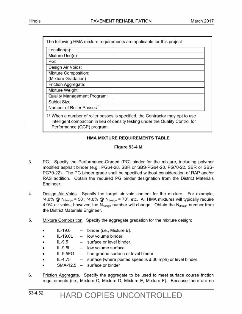
Illinois PAVEMENT REHABILITATION March 2017
53-4.52 HARD COPIES UNCONTROLLED
The following HMA mixture requirements are applicable for this project:
Location(s): Mixture Use(s): PG: Design Air Voids: Mixture Composition: (Mixture Gradation)
Friction Aggregate: Mixture Weight: Quality Management Program: Sublot Size: Number of Roller Passes 1/
1/ When a number of roller passes is specified, the Contractor may opt to use intelligent compaction in lieu of density testing under the Quality Control for Performance (QCP) program.
HMA MIXTURE REQUIREMENTS TABLE
Figure 53-4.M
3. PG. Specify the Performance-Graded (PG) binder for the mixture, including polymer
modified asphalt binder (e.g., PG64-28, SBR or SBS-PG64-28, PG70-22, SBR or SBS-PG70-22). The PG binder grade shall be specified without consideration of RAP and/or RAS addition. Obtain the required PG binder designation from the District Materials Engineer.
4. Design Air Voids. Specify the target air void content for the mixture. For example, “4.0% @ Ndesign = 50”, “4.0% @ Ndesign = 70”, etc. All HMA mixtures will typically require 4.0% air voids; however, the Ndesign number will change. Obtain the Ndesign number from the District Materials Engineer.
5. Mixture Composition. Specify the aggregate gradation for the mixture design:
IL-19.0 – binder (i.e., Mixture B). IL-19.0L – low volume binder. IL-9.5 – surface or level binder. IL-9.5L – low volume surface. IL-9.5FG – fine-graded surface or level binder. IL-4.75 – surface (where posted speed is ≤ 30 mph) or level binder. SMA-12.5 – surface or binder
6. Friction Aggregate. Specify the aggregate to be used to meet surface course friction requirements (i.e., Mixture C, Mixture D, Mixture E, Mixture F). Because there are no
Illinois PAVEMENT REHABILITATION March 2017
53-4.53 HARD COPIES UNCONTROLLED
friction requirements for binder courses, leave this entry blank when specifying binder courses. Refer to Section 53-4.07(d) for additional information.
7. Mixture Weight. Specify the unit weight used to determine the plan quantities for HMA surface course. Use 112.0 lb/sq yd/in. thickness as the unit weight for typical standard mixes using natural aggregate. For a specialty mix design, such as those using synthetic aggregates with differing unit weights (e.g., air-cooled blast furnace slag (light) or steel slag (heavy)), the designer should consult the District Materials Engineer to determine the anticipated unit weight.
8. Quality Management Program. Specify which quality management program will be used for each mixture use listed in Item 2 above. If a mixture has multiple applications, more than one management program can be provided. Options include: Pay-For-Performance (PFP), Quality Control for Performance (QCP), and Quality Control/Quality Assurance (QC/QA).
a. PFP. PFP utilizes pay adjustments based upon percent within limits statistical calculations. PFP should be specified for interstate, freeway and expressway binder and surface mixtures; and full-depth pavement projects having a minimum quantity of 8000 tons (7260 metric tons) per mix. PFP may also be considered for smaller projects where a more accurate measure of quality is desired. PFP should not be used on:
leveling binder; incidental surfacing (e.g. entrances, minor sideroads); temporary pavements; shoulders, unless they are used as auxiliary lanes, patching; or applications where the mixture thickness is less than 3 times the nominal
maximum aggregate size.
b. QCP. QCP utilizes step-based pay adjustments and should be specified for:
mainline mixture quantities between 1,200 and 8,000 tons (1,016 and 7,620 metric tons);
shoulder applications that are greater than 8 feet (2.4 meters) wide and having quantities of 1,200 tons (1,016 metric tons) and greater; and
leveling binder applications that are 1,200 tons (1,016 metric tons) and greater.
c. QC/QA. The use of QC/QA is limited to:
mixtures with quantities less than 1,200 tons (1,016 metric tons), shoulders placed with a road widener, and patching or incidental surfacing (e.g. entrances, minor sideroads).
9. Sublot Size. The sublot size for QCP and PFP will typically be 1000 tons. On rare occasions, the sublot size may be reduced to lower the payment risk for smaller tonnage
Illinois PAVEMENT REHABILITATION March 2017
53-4.54 HARD COPIES UNCONTROLLED
projects. Sublot size is not applicable when the QC/QA quality management program is used.
10. Number of Roller Passes. To give the Contractor the option of using intelligent compaction in lieu of density testing for variable depth leveling binder (i.e. used to correct cross-slope or rutting) placed under the QCP quality management program, specify the number of passes (typically 5 passes or 7 passes) the rollers must make over the leveling binder to ensure enough compactive effort is being applied.
53-4.07(a) ESAL Calculation
Use Section 54-2.01(c) to calculate ESALs for the design lane. To select the PG binder and design compactive effort (Ndesign), the ESAL value, equivalent to the Traffic Factor (TF), is calculated according to the equations in Figure 54-5.B. Use a Design Period (DP) of 20 years. In this application, the calculation is purely to determine the mixture design parameters; actual pavement/thickness design may require a different design period and/or TF calculation. Minimum structural design traffic levels should be ignored for mixture design purposes.
It is recommended that each district designate a single individual to coordinate ESAL calculations. In instances where major routes cross district borders, it is recommended that the ESAL counts be confirmed between districts.
53-4.07(b) Design Compactive Effort
The design compactive effort is expressed as an Ndesign number, which is selected based on the estimated 20-year ESAL loading of the traffic lane.
Figure 53-4.N lists the design compactive effort (Ndesign) required for the different levels of traffic loading and describes the typical roadway application. Consult the District Materials Engineer for the appropriate Ndesign value.
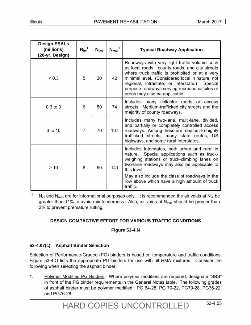
Illinois PAVEMENT REHABILITATION March 2017
53-4.55 HARD COPIES UNCONTROLLED
Design ESALs (millions)
(20-yr. Design) Nini
1 Ndes Nmax
1 Typical Roadway Application
< 0.3 5 30 42
Roadways with very light traffic volume such as local roads, county roads, and city streets where truck traffic is prohibited or at a very minimal level. (Considered local in nature; not regional, intrastate, or interstate.) Special purpose roadways serving recreational sites or areas may also be applicable.
0.3 to 3 6 50 74 Includes many collector roads or access streets. Medium-trafficked city streets and the majority of county roadways.
3 to 10 7 70 107
Includes many two-lane, multi-lane, divided, and partially or completely controlled access roadways. Among these are medium-to-highly trafficked streets, many state routes, US highways, and some rural Interstates.
> 10 8 90 141
Includes Interstates, both urban and rural in nature. Special applications such as truck-weighing stations or truck-climbing lanes on two-lane roadways may also be applicable to this level.
May also include the class of roadways in the row above which have a high amount of truck traffic.
1 Nini and Nmax are for informational purposes only. It is recommended the air voids at Nini be greater than 11% to avoid mix tenderness. Also, air voids at Nmax should be greater than 2% to prevent premature rutting.
DESIGN COMPACTIVE EFFORT FOR VARIOUS TRAFFIC CONDITIONS
Figure 53-4.N
53-4.07(c) Asphalt Binder Selection
Selection of Performance-Graded (PG) binders is based on temperature and traffic conditions. Figure 53-4.O lists the appropriate PG binders for use with all HMA mixtures. Consider the following when selecting the asphalt binder:
1. Polymer Modified PG Binders. Where polymer modifiers are required, designate “SBS” in front of the PG binder requirements in the General Notes table. The following grades of asphalt binder must be polymer modified: PG 64-28, PG 70-22, PG70-28, PG76-22, and PG76-28.
Illinois PAVEMENT REHABILITATION March 2017
53-4.56 HARD COPIES UNCONTROLLED
2. Overlays of PCC or Composite Pavements. Overlays of PCC or composite pavements should use the grades shown in Figure 53-4.O for a standard traffic level. Adjustments to this grade are dependent upon conditions such as slow moving traffic, high ESALs, or standing traffic. These modifications should be made for the corresponding Ndesign number and/or ESAL number. The appropriate asphalt binder grade should then be reported on the General Notes table of the plans.
3. Full-Depth HMA Pavements or Overlays of Full-Depth HMA Pavements. Full-depth HMA pavements or overlays of full-depth HMA pavements should be designed using the PG binders shown in Figure 53-4.O. The appropriate binder grade should be reported on the General Notes table of the project plans.
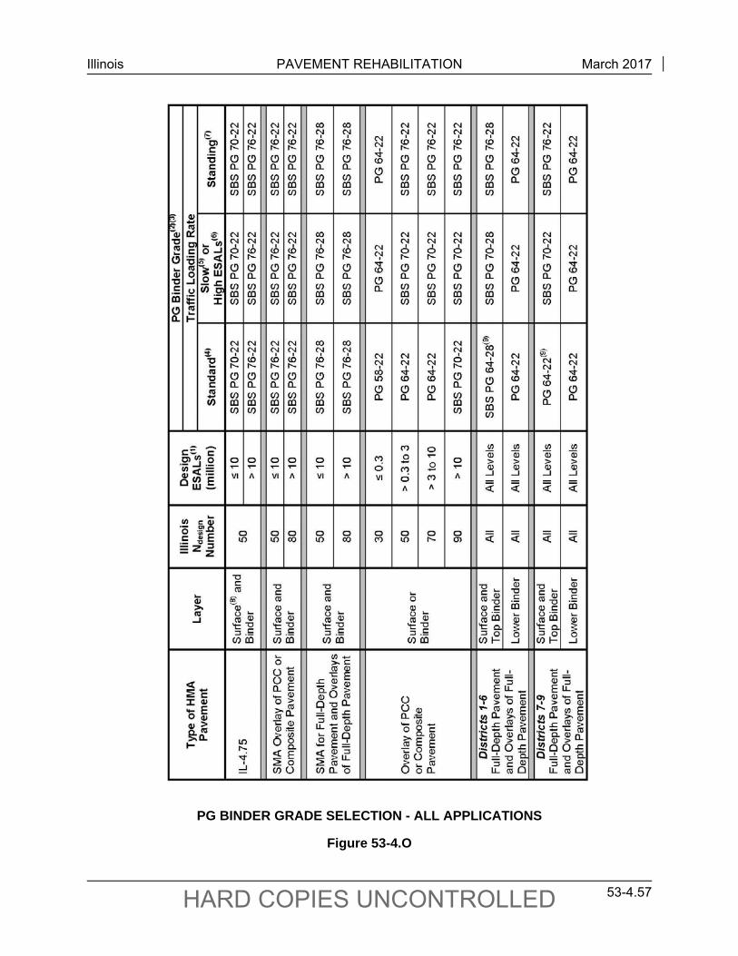
Illinois PAVEMENT REHABILITATION March 2017
53-4.57 HARD COPIES UNCONTROLLED
PG BINDER GRADE SELECTION - ALL APPLICATIONS
Figure 53-4.O
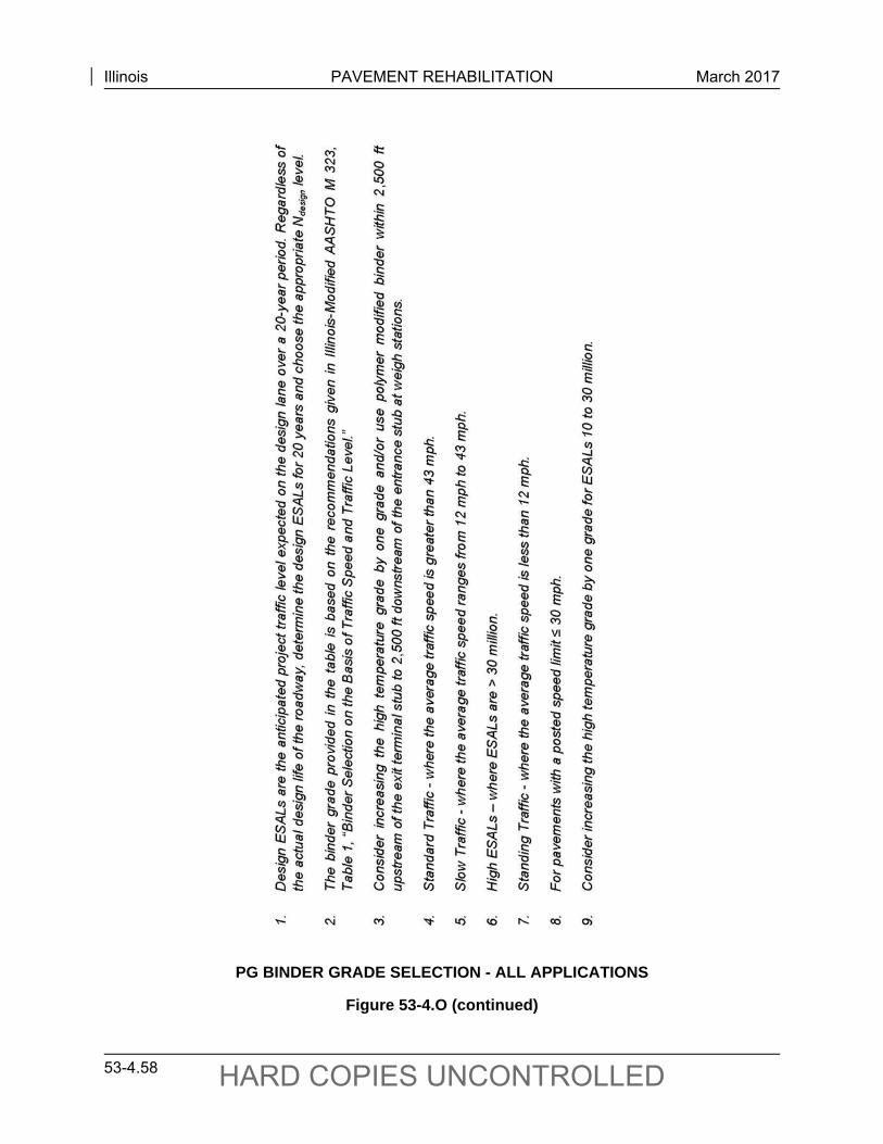
Illinois PAVEMENT REHABILITATION March 2017
53-4.58 HARD COPIES UNCONTROLLED
PG BINDER GRADE SELECTION - ALL APPLICATIONS
Figure 53-4.O (continued)
Illinois PAVEMENT REHABILITATION March 2017
53-4.59 HARD COPIES UNCONTROLLED
53-4.07(d) Friction Aggregate
An HMA surface course must be specified for each rehabilitation/resurfacing project. Section 11-2.02(f) gives safety analysis procedures to determine risks contributing to substantive safety problems.
Before the appropriate mix is selected, determine whether or not pavement surface friction is contributing to a substantive safety problem at the site. Presence of “wet pavement” crashes alone is not sufficient, as other risks related to wet weather may be present. For example, inadequate warning signage or visibility of stop or maneuver areas, unexpected geometric conditions, rutting, lack of surface drainage, inadequate pavement cross slope, or excess spray from vehicle tires may be more important than surface friction for locations of wet pavement crashes. Review of crash reports including narratives and sketches, site reviews during wet conditions, and surface friction testing should be included in an analysis of wet pavement crashes. Pavement friction testing may be requested according to the Bureau of Materials and Physical Research Pavement Technology Advisory-“Testing Pavement Friction” (PTA-T3), http://idot.illinois.gov/Assets/uploads/files/Transportation-System/Research/Pavement-Technology-Advisories/Testing-and-Data-Collection-Series/PTAT3.pdf.
If the segment demonstrates a pattern of wet pavement crashes, identification of the risks contributing to the crash pattern will help to indicate the appropriate countermeasures, possibly including improved positive guidance, geometric changes, surface to full-depth repairs of rutting, improved drainage or cross slope, or improved surface texture (pavement grooving) or resurfacing with appropriate friction aggregate.
It is not desirable to specify short, closely spaced segments of special high-quality friction mixes (i.e., patchwork surfacing). If a higher-quality friction mix treatment is required at more than one location on a project and the distance between locations is less than 1,000 ft, the gaps should also be treated with the higher-quality mix. Also, if the special treatment is required on more than 50 percent of the project, it should be used throughout the entire project.
Four surface course mixtures have been developed that will provide adequate skid resistance for various Average Daily Traffic (ADT) levels: Mixtures C, D, E, and F. Figure 53-4.P designates the ADT levels allowable for each of the surface course mixtures.
It is expected that the application of friction aggregate according to Figure 53-4.P will address most pavement friction needs. However, some conditions create friction demands exceeding typical conditions anticipated by this tabulation. Examples include locations where problem identification shows a pattern of wet pavement related crashes and one of the following conditions:
on grades exceeding 3.5%;
locations with a heavy commercial vehicle (HCV) volume (Single Units plus Multiple Units) exceeding 400 per day and equal to 25% or more of the total ADT (Note – 25% HCV represents about 15% of State System mileage);
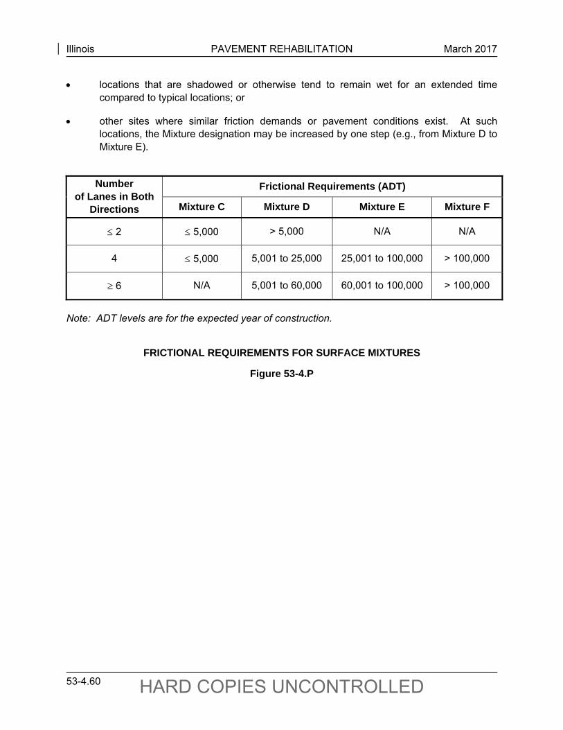
Illinois PAVEMENT REHABILITATION March 2017
53-4.60 HARD COPIES UNCONTROLLED
locations that are shadowed or otherwise tend to remain wet for an extended time compared to typical locations; or
other sites where similar friction demands or pavement conditions exist. At such locations, the Mixture designation may be increased by one step (e.g., from Mixture D to Mixture E).
Number
of Lanes in Both Directions
Frictional Requirements (ADT)
Mixture C Mixture D Mixture E Mixture F
2 5,000 > 5,000 N/A N/A
4 5,000 5,001 to 25,000 25,001 to 100,000 > 100,000
6 N/A 5,001 to 60,000 60,001 to 100,000 > 100,000
Note: ADT levels are for the expected year of construction.
FRICTIONAL REQUIREMENTS FOR SURFACE MIXTURES
Figure 53-4.P
Illinois PAVEMENT REHABILITATION March 2017
53-4.61 HARD COPIES UNCONTROLLED
53-4.08 PCC Inlay/Overlay Design Guidelines
The stopping, starting, standing, and turning actions of vehicles at intersections or other locations may create rutting and other severe conditions for pavement structures with HMA surfaces. The volume and type of vehicles may also distress HMA surfaces. Standing water in ruts (e.g., from rain events) may create a hydroplaning hazard. In addition, snow and ice left in the ruts after snowplowing may be hazardous to the traveling public. Therefore, a PCC inlay/overlay may be a better alternative than HMA. The PCC inlay/overlay has no risk for rutting and a longer service life may be achieved.
A PCC inlay/overlay consists of placing a thin concrete layer on an existing HMA surface. Construction of an inlay/overlay includes milling the existing rutted HMA to correct longitudinal profile and cross-slope irregularities and providing a surface for bonding of the overlay. A PCC inlay/overlay may be considered as an alternative at intersections or other locations where HMA overlays have shown a tendency to rut or have shortened performance lives.
Synthetic fibers are required where the inlay/overlay is 4.0 in. or less, and optional where it exceeds 4.0 in. The synthetic fibers currently used are much different from the fibers originally used in inlay/overlay projects. The original fibers used were mainly to prevent plastic shrinkage cracks. The new fibers will provide structural reinforcement, which will increase flexural toughness and cracking resistance.
These procedures do not apply to a thickness greater than 6.0 in. which is considered an unbonded concrete inlay/overlay.
53-4.08(a) Applicability
These guidelines have been prepared for a rehabilitation strategy that involves a 3.0 in. to 6.0 in. PCC inlay/overlay bonded to a pavement structure that has an HMA surface. This rehabilitation strategy has been previously known as ultrathin whitetopping.
These guidelines may be used to evaluate pavement at an existing intersection or other locations to determine if use of a PCC inlay/overlay is feasible and constructible. These guidelines also contain design steps needed to successfully complete this option. A PCC inlay/overlay requires a thorough review of the existing pavement structure, as well as close attention to utility, profile, and elevation adjustments. This technique requires a bonding action to the underlying HMA surface and multiple joints at an early age to control cracking and curling stresses within the inlay/overlay.
These guidelines are to be followed to review the existing pavement structure, identify design considerations, and prepare a request for review and approval of a PCC inlay/overlay system.
53-4.08(b) Limitations
Performance of PCC inlay/overlay sections can be variable because of the underlying pavement structure. The designer should consider the general constructability of a PCC inlay/overlay at

Illinois PAVEMENT REHABILITATION March 2017
53-4.62 HARD COPIES UNCONTROLLED
the selected location. The existing HMA layer that is to remain in place shall be a minimum of 2.5 in. thick. If a portion of the PCC inlay/overlay in excess of 5% will be bonded directly to bare concrete, brick, or other old slabs of concrete, this rehabilitation method shall not be used. The 5% limitation is to allow for existing concrete patches or other existing pavement features. Construction is also hindered by complicated geometrics, utility obstructions, traffic demand, and condition of the existing pavement.
The term PCC inlay can be defined as a very minor or no change in grade; and, as such, could limit its use in areas where profile adjustments would be limited (e.g., with existing curb and gutter sections). A PCC overlay would be used where profile grade adjustments are feasible.
This alternative rehabilitation strategy shall apply to Class I, II, III, and IV pavements, but shall not be used for Federal-aid Interstates or when the traffic factor (based on the rigid pavement equations) exceeds 5.0.
53-4.08(c) Procedures
All proposed PCC inlay/overlay projects must be submitted to BDE for approval. The request should be documented in a “PCC Inlay/Overlay Project Request Report” and should include the following:
a report of the preliminary and detailed pavement investigations,
existing and proposed cross sections,
existing and projected traffic information,
construction sequencing and proposed traffic control,
a cost analysis for each rehabilitation alternative, and
a summary on why a PCC inlay/overlay is the preferred method of rehabilitation over other alternatives.
Guidelines regarding the items to be included in the report and other design details for a PCC inlay/overlay are discussed in the following sections. The designer should review all requirements and do preliminary calculations to check the feasibility of this process before proceeding with some of the detailed investigations.
1. Review of Existing Pavement Structure. A thorough investigation of the existing pavement structure should be conducted. The purpose of this investigation is to determine if the section in question is suitable for a PCC inlay/overlay. It is essential that only appropriate sections be selected for this rehabilitation option.
a. Preliminary Pavement Investigation, Design, and Traffic Factor Considerations. The designer should research past rehabilitation attempts as well as future plans for the area that surrounds the intersection/roadway. Research of past
Illinois PAVEMENT REHABILITATION March 2017
53-4.63 HARD COPIES UNCONTROLLED
rehabilitation attempts will provide information on why past rehabilitation methods have not performed as designed. Insight into future plans for the pavement and area surrounding the project may influence the design of the rehabilitation. The designer should check to see if any of the limitations of this application apply.
If it appears that a PCC inlay/overlay can be constructed, then a detailed pavement investigation is necessary to verify the constructability of the inlay/overlay.
b. Detailed Pavement Investigation. Upon completion of the preliminary investigation, a detailed pavement coring plan should be developed and administered according to Section 53-3.08. In general, cores will be taken to represent all pavement cross sections and all locations within the project. The coring plan should be completed to specifically address the following points:
total pavement thickness and thickness for each layer of concrete or HMA detected;
condition, tensile strength, and presence of stripping for each HMA layer;
condition, compressive strength (optional), presence of D-cracking, and presence of alkali-silica reaction for each concrete layer; and
identification of locations where patching or alternative rehabilitation methods are recommended.
In addition to the coring plan, a general inspection of project limits should be completed. In general, the inspection will address items such as geometrics, drainage, utilities, and surface abnormalities. More specifically, the inspection should address the following points:
intersection of pavement crowns (multi-leg intersections);
location of drop inlets;
location of loop detectors for traffic signals (detector loops would be installed into the milled surface);
location of sewer manholes, water valves, and all other utility obstructions;
location of existing surface patches;
location of high-severity distresses;
location of HMA rutting exceeding 0.35 in.; and
clearances for overheads.
Illinois PAVEMENT REHABILITATION March 2017
53-4.64 HARD COPIES UNCONTROLLED
c. Existing and Projected Average Daily Traffic. An accurate count of the existing Average Daily Traffic (ADT) with a breakdown of percentages for passenger vehicles, single unit, and multiple unit trucks should be performed. In addition, estimates for the projected ADT and classification breakdown should be developed for the design period.
Upon completion of coring and inspection procedures, and collection of traffic data, a report should be created to document this information.
2. Identify Design Considerations. There are several design issues that must be considered before a PCC inlay/overlay project can be submitted for review and approval. A list of issues that may be resolved prior to the submittal of a design is as follows:
a. Design Period. The design period to be used for this rehabilitation strategy is 15 years.
b. Cost Alternatives. A cost analysis of several different rehabilitation options is required. Cost analyses include initial construction cost, annual maintenance cost, and expected lifespan of the rehabilitation option. However, the annual maintenance cost information involving an inlay/overlay using the new stronger synthetic fibers is currently limited. It is suggested to contact the Bureau of Materials and Physical Research for assistance. Cost alternatives may also include various options within the same rehabilitation technique.
c. Drainage Considerations. Maintaining proper drainage through design and during construction is important. During construction, maintaining drainage is especially critical for projects that include an inlay.
d. Pavement Preparation and Profile. The existing pavement surface shall be milled to correct longitudinal profile and cross-slope irregularities, remove any foreign materials, and remove oxidized HMA from the surface. Milling will also increase the surface area for bonding of the PCC inlay/overlay. If patching will be required on the project, the designer needs to keep in mind that the five percent limitation for bonding the PCC inlay/overlay to concrete still applies. Refer to Section 53-4.08(c)1.a.
e. Thickness Design and Joint Spacing. The PCC inlay/overlay thickness design is based on traffic factor, underlying HMA thickness, panel size, and fibers/no fibers. The inlay/overlay shall be 3.0 in. to 6.0 in. with 0.50 in. increments allowed.
The traffic factor shall be determined according to the applicable equation for each pavement class using the equations in Section 54-4.01(g). Based on the traffic factor, the thickness of the underlying HMA material, panel size, and fibers/no fibers, the PCC inlay/overlay thickness may be determined either from Figures 53-4.Q through 53-4.X or by using a computer program which is available from BDE: www.dot.il.gov/desenv/pdp.html.
Illinois PAVEMENT REHABILITATION March 2017
53-4.65 HARD COPIES UNCONTROLLED
This program allows the designer to input the traffic factor, the thickness of the underlying HMA material, panel size, and fibers/no fibers to calculate the PCC inlay/overlay thickness. The result from the program is rounded up to the nearest 0.50 in.
The thicknesses shown in Figures 53-4.Q through 53-4.X were calculated using the computer program with the following default values as design inputs:
Elastic Modulus of HMA Layer (EAC) = 350,000 psi Elastic Modulus of PCC Overlay or Inlay (EC) = 3,600,000 psi Modulus of Rupture (MOR) = 750 psi Modulus of Subgrade (k)= 100 pci Coefficient of Thermal Expansion (CTE) = 5.5 x 10⁻⁶ in./in./°F Percent of Panels with Cracking (Pcr) = 20% Reliability Factor (R) = 85% Temperature Gradient (∆T) = -1.4 °F/in. Occurrence of Temperature Gradient (% Time) = 58%
A key to the success of a PCC inlay/overlay is longitudinal and transverse joints. These joints are hand tooled into plastic concrete or sawed into hardened concrete to provide stress relief induced by drying shrinkage and curling of concrete. Hand tooled joints are not used on mainline pavement with a posted speed limit greater than 40 mph because they may not be as smooth as a sawed joint, resulting in a rougher ride. The joints should be laid out on a regular pattern for both longitudinal and transverse directions (to form squares) based on the spacing used to determine the thickness. No skewed joints will be allowed.
Transverse and longitudinal joints should be laid out to match joints, utility obstructions, and geometrics of the existing pavement when PCC pavement is exposed during milling. When feasible, longitudinal joints should be laid out to avoid the wheelpath areas of the traveling lanes. The layout of all transverse and longitudinal joints should be detailed on the plan sheets.
The cost of sawing may significantly influence the cost of an inlay/overlay. A thicker inlay/overlay may be more economical than a thinner one because the greater thickness may increase the joint spacing, resulting in less sawing. In addition, the use of synthetic fibers for inlays/overlays greater than 4.0 in. may be more economical than inlays/overlays without them because the synthetic fibers may increase the joint spacing. Again, the amount of sawing is reduced.
The following list defines the variables shown in Figures 53-4.Q through 53-4.X.
R150,3 = Residual Strength Ratio (percent); where the net deflection is calculated as L/150 (L = span length) and is limited to 3 mm.
hac = Thickness of existing hot-mix asphalt remaining after milling.
hc = Thickness of new PCC inlay/overlay.
L = Joint spacing for longitudinal and transverse directions.
Illinois PAVEMENT REHABILITATION March 2017
53-4.66 HARD COPIES UNCONTROLLED
f. Final Finish. Locations with a posted speed limit greater than 40 mph shall use a Type A final finish. All other locations shall use a rough broom final finish struck perpendicular to the direction of traffic flow in lieu of a Type B final finish. The rough broom finish shall be used across the entire surface area of the inlay/overlay including any hand-tooled joints.
g. Traffic Control. The control of traffic through the project must be considered and well established prior to time of construction. The best alternative for traffic control is to completely close the project to traffic. This alternative may be difficult for urban projects; however, somewhat easier for rural projects. If closure to traffic is not possible, traffic control must be established that will effectively move traffic through the project with minimal disruption to construction operations and traffic flow. Traffic control that can be left unattended overnight must be anticipated for each stage of construction.
h. Construction Staging. Construction staging for a PCC inlay/overlay project must be considered with respect to the construction timeframe and traffic flow through the project. The project must be staged in such a way that continuous traffic flow will be maintained. Construction staging must also consider the geometrics of the project and any lane to lane drop off restrictions that may be present with the overlay thickness.
These inlays/overlays have a traffic opening strength of 550 psi flexural or 3,000 psi compressive. The current PCC mix design specified may obtain the opening strength in as little as three days if properly proportioned. If the inlay/overlay must be opened to traffic in a shorter time frame, consult the District Materials Office for an acceptable high-early-strength PCC mixture.
3. Request for Review and Approval. Upon Completion of the PCC inlay/overlay investigation, the completed “PCC Inlay/Overlay Project Request Report” should be submitted to BDE for review and approval.
If the program is used in lieu of Figures 53-4.Q through 53-4.X to determine the thickness, the PCC Inlay/Overlay Project Request Report must include copies of the screens from the program indicating the inputs used for the design.
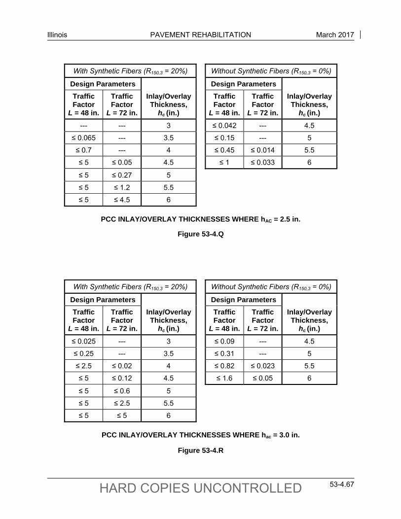
Illinois PAVEMENT REHABILITATION March 2017
53-4.67 HARD COPIES UNCONTROLLED
With Synthetic Fibers (R150,3 = 20%) Without Synthetic Fibers (R150,3 = 0%)
Design Parameters Design Parameters
Traffic Factor
L = 48 in.
Traffic Factor
L = 72 in.
Inlay/Overlay Thickness,
hc (in.)
Traffic Factor
L = 48 in.
Traffic Factor
L = 72 in.
Inlay/Overlay Thickness,
hc (in.)
--- --- 3 ≤ 0.042 --- 4.5
≤ 0.065 --- 3.5 ≤ 0.15 --- 5
≤ 0.7 --- 4 ≤ 0.45 ≤ 0.014 5.5
≤ 5 ≤ 0.05 4.5 ≤ 1 ≤ 0.033 6
≤ 5 ≤ 0.27 5
≤ 5 ≤ 1.2 5.5
≤ 5 ≤ 4.5 6
PCC INLAY/OVERLAY THICKNESSES WHERE hAC = 2.5 in.
Figure 53-4.Q
With Synthetic Fibers (R150,3 = 20%) Without Synthetic Fibers (R150,3 = 0%)
Design Parameters Design Parameters
Traffic Factor
L = 48 in.
Traffic Factor
L = 72 in.
Inlay/Overlay Thickness,
hc (in.)
Traffic Factor
L = 48 in.
Traffic Factor
L = 72 in.
Inlay/Overlay Thickness,
hc (in.)
≤ 0.025 --- 3 ≤ 0.09 --- 4.5
≤ 0.25 --- 3.5 ≤ 0.31 --- 5
≤ 2.5 ≤ 0.02 4 ≤ 0.82 ≤ 0.023 5.5
≤ 5 ≤ 0.12 4.5 ≤ 1.6 ≤ 0.05 6
≤ 5 ≤ 0.6 5
≤ 5 ≤ 2.5 5.5
≤ 5 ≤ 5 6
PCC INLAY/OVERLAY THICKNESSES WHERE hac = 3.0 in.
Figure 53-4.R
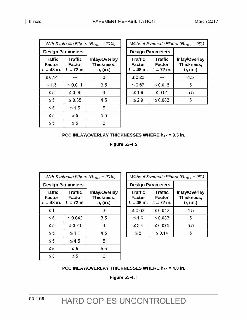
Illinois PAVEMENT REHABILITATION March 2017
53-4.68 HARD COPIES UNCONTROLLED
With Synthetic Fibers (R150,3 = 20%) Without Synthetic Fibers (R150,3 = 0%)
Design Parameters Design Parameters
Traffic Factor
L = 48 in.
Traffic Factor
L = 72 in.
Inlay/Overlay Thickness,
hc (in.)
Traffic Factor
L = 48 in.
Traffic Factor
L = 72 in.
Inlay/Overlay Thickness,
hc (in.)
≤ 0.14 --- 3 ≤ 0.23 --- 4.5
≤ 1.3 ≤ 0.011 3.5 ≤ 0.67 ≤ 0.016 5
≤ 5 ≤ 0.06 4 ≤ 1.6 ≤ 0.04 5.5
≤ 5 ≤ 0.35 4.5 ≤ 2.9 ≤ 0.083 6
≤ 5 ≤ 1.5 5
≤ 5 ≤ 5 5.5
≤ 5 ≤ 5 6
PCC INLAY/OVERLAY THICKNESSES WHERE hAC = 3.5 in.
Figure 53-4.S
With Synthetic Fibers (R150,3 = 20%) Without Synthetic Fibers (R150,3 = 0%)
Design Parameters Design Parameters
Traffic Factor
L = 48 in.
Traffic Factor
L = 72 in.
Inlay/Overlay Thickness,
hc (in.)
Traffic Factor
L = 48 in.
Traffic Factor
L = 72 in.
Inlay/Overlay Thickness,
hc (in.)
≤ 1 --- 3 ≤ 0.63 ≤ 0.012 4.5
≤ 5 ≤ 0.042 3.5 ≤ 1.6 ≤ 0.033 5
≤ 5 ≤ 0.21 4 ≤ 3.4 ≤ 0.075 5.5
≤ 5 ≤ 1.1 4.5 ≤ 5 ≤ 0.14 6
≤ 5 ≤ 4.5 5
≤ 5 ≤ 5 5.5
≤ 5 ≤ 5 6
PCC INLAY/OVERLAY THICKNESSES WHERE hAC = 4.0 in.
Figure 53-4.T
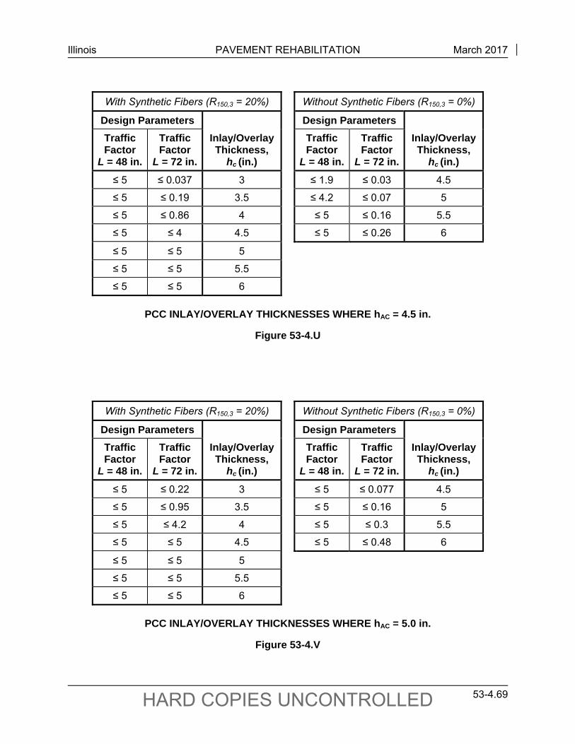
Illinois PAVEMENT REHABILITATION March 2017
53-4.69 HARD COPIES UNCONTROLLED
With Synthetic Fibers (R150,3 = 20%) Without Synthetic Fibers (R150,3 = 0%)
Design Parameters Design Parameters
Traffic Factor
L = 48 in.
Traffic Factor
L = 72 in.
Inlay/Overlay Thickness,
hc (in.)
Traffic Factor
L = 48 in.
Traffic Factor
L = 72 in.
Inlay/Overlay Thickness,
hc (in.)
≤ 5 ≤ 0.037 3 ≤ 1.9 ≤ 0.03 4.5
≤ 5 ≤ 0.19 3.5 ≤ 4.2 ≤ 0.07 5
≤ 5 ≤ 0.86 4 ≤ 5 ≤ 0.16 5.5
≤ 5 ≤ 4 4.5 ≤ 5 ≤ 0.26 6
≤ 5 ≤ 5 5
≤ 5 ≤ 5 5.5
≤ 5 ≤ 5 6
PCC INLAY/OVERLAY THICKNESSES WHERE hAC = 4.5 in.
Figure 53-4.U
With Synthetic Fibers (R150,3 = 20%) Without Synthetic Fibers (R150,3 = 0%)
Design Parameters Design Parameters
Traffic Factor
L = 48 in.
Traffic Factor
L = 72 in.
Inlay/Overlay Thickness,
hc (in.)
Traffic Factor
L = 48 in.
Traffic Factor
L = 72 in.
Inlay/Overlay Thickness,
hc (in.)
≤ 5 ≤ 0.22 3 ≤ 5 ≤ 0.077 4.5
≤ 5 ≤ 0.95 3.5 ≤ 5 ≤ 0.16 5
≤ 5 ≤ 4.2 4 ≤ 5 ≤ 0.3 5.5
≤ 5 ≤ 5 4.5 ≤ 5 ≤ 0.48 6
≤ 5 ≤ 5 5
≤ 5 ≤ 5 5.5
≤ 5 ≤ 5 6
PCC INLAY/OVERLAY THICKNESSES WHERE hAC = 5.0 in.
Figure 53-4.V
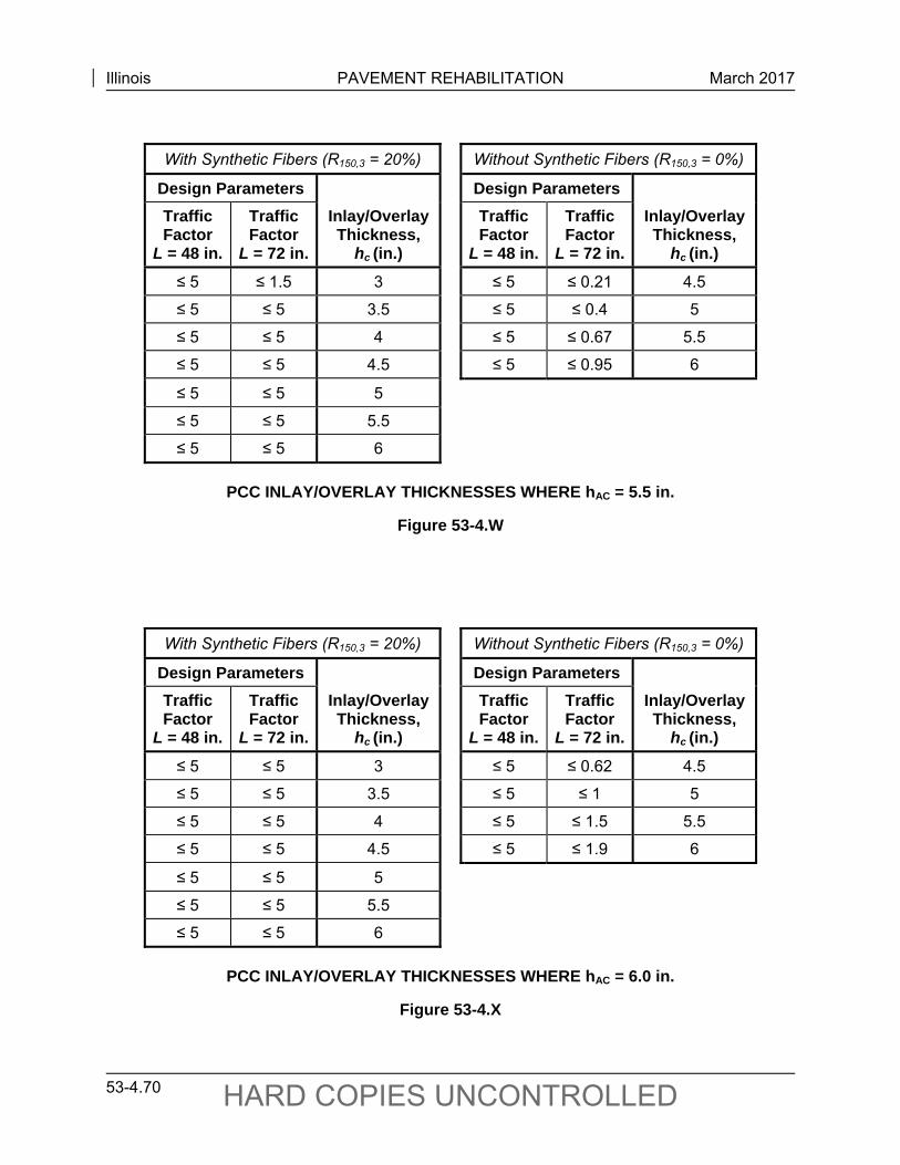
Illinois PAVEMENT REHABILITATION March 2017
53-4.70 HARD COPIES UNCONTROLLED
With Synthetic Fibers (R150,3 = 20%) Without Synthetic Fibers (R150,3 = 0%)
Design Parameters Design Parameters
Traffic Factor
L = 48 in.
Traffic Factor
L = 72 in.
Inlay/Overlay Thickness,
hc (in.)
Traffic Factor
L = 48 in.
Traffic Factor
L = 72 in.
Inlay/Overlay Thickness,
hc (in.)
≤ 5 ≤ 1.5 3 ≤ 5 ≤ 0.21 4.5
≤ 5 ≤ 5 3.5 ≤ 5 ≤ 0.4 5
≤ 5 ≤ 5 4 ≤ 5 ≤ 0.67 5.5
≤ 5 ≤ 5 4.5 ≤ 5 ≤ 0.95 6
≤ 5 ≤ 5 5
≤ 5 ≤ 5 5.5
≤ 5 ≤ 5 6
PCC INLAY/OVERLAY THICKNESSES WHERE hAC = 5.5 in.
Figure 53-4.W
With Synthetic Fibers (R150,3 = 20%) Without Synthetic Fibers (R150,3 = 0%)
Design Parameters Design Parameters
Traffic Factor
L = 48 in.
Traffic Factor
L = 72 in.
Inlay/Overlay Thickness,
hc (in.)
Traffic Factor
L = 48 in.
Traffic Factor
L = 72 in.
Inlay/Overlay Thickness,
hc (in.)
≤ 5 ≤ 5 3 ≤ 5 ≤ 0.62 4.5
≤ 5 ≤ 5 3.5 ≤ 5 ≤ 1 5
≤ 5 ≤ 5 4 ≤ 5 ≤ 1.5 5.5
≤ 5 ≤ 5 4.5 ≤ 5 ≤ 1.9 6
≤ 5 ≤ 5 5
≤ 5 ≤ 5 5.5
≤ 5 ≤ 5 6
PCC INLAY/OVERLAY THICKNESSES WHERE hAC = 6.0 in.
Figure 53-4.X
Illinois PAVEMENT REHABILITATION September 2010
53-5.1 HARD COPIES UNCONTROLLED
53-5 LIFE-CYCLE COST ANALYSIS FOR REHABILITATION PROJECTS
This section provides guidance on conducting Life-Cycle Cost Analyses (LCCA) for pavement rehabilitation projects to assess the long-term cost effectiveness of alternative rehabilitation strategies.
53-5.01 Purpose of LCCA
The LCCA is an analytical technique, based on the principles of economic analysis, that evaluates the overall long-term economic efficiency among competing alternative rehabilitation strategies. LCCA does not, however, address equity issues. It incorporates initial and discounted future Department, user, and other relevant costs over the life of candidate alternatives. LCCA attempts to identify the best value for investment expenditures (i.e., the lowest long-term cost that satisfies the performance objective). Note that LCCA is a decision support tool, and the results of using LCCA are not decisions in and of themselves. The logical analytical evaluation framework that life-cycle cost analyses foster is as important as the LCCA results themselves. It is essential that all impacts be accurate for LCCA results to be meaningful.
53-5.02 LCCA Procedures
The LCCA should be conducted as early in the project development cycle as practicable. For rehabilitation projects, the appropriate time for conducting the LCCA is during the alternatives evaluation stage of Phase I. The level of detail included in the LCCA should be consistent with the level of investment. Typical LCCA models that are based on primary rehabilitation strategies can be used to reduce unnecessarily repetitive analyses.
The LCCA need only consider differential costs among rehabilitation alternatives. Costs common to all alternatives will cancel out and should not be included in the analysis. Inclusion of all potential LCCA factors in every analysis is counterproductive; however, all LCCA factors and assumptions should be addressed, even if only limited to an explanation of the rationale for not including eliminated factors in detail. Sunk costs, which are irrelevant to the analysis, should not be included.
53-5.03 LCCA Guidelines
Consider the following guidelines when conducting life-cycle costs analyses to assess rehabilitation project alternatives:
11. LCCA Analysis Period. The LCCA analysis period, or the time horizon over which rehabilitation alternatives are evaluated, should be sufficient to reflect long-term cost differences associated with reasonable strategies. An analysis period of 30 to 40 years is reasonable for rehabilitation projects.
Illinois PAVEMENT REHABILITATION September 2010
53-5.2 HARD COPIES UNCONTROLLED
12. Economic Efficiency Indicator. Net present value (NPV) is the economic efficiency indicator of choice. The uniform equivalent annual cost (UEAC) indicator is also acceptable, but should be derived from NPV. Computation of benefit/cost (B/C) ratios are generally not recommended because of the difficulty in determining costs and benefits for B/C ratios.
13. Dollar Type. Future cost and benefit streams should be estimated in constant dollars and discounted to the present using a real discount rate. Although nominal dollars can be used with nominal discount rates, use of real/constant dollars and real discount rates eliminates the need to estimate and include an inflation premium. In any given LCCA, real/constant or nominal dollars must not be mixed (i.e., all costs must be in real dollars or all costs must be in nominal dollars). Furthermore, the discount rate selected must be consistent with the dollar type used (i.e., use real cost and real discount rate or nominal cost and nominal discount rate).
14. Discount Rate. The Department uses a discount rate of 3% for new pavements and this rate is acceptable for rehabilitation.
15. Overhead Costs. Although most analyses include traditional Department construction costs, some do not fully account for the Departments engineering and construction management overhead. This can be a serious oversight on short-lived rehabilitation projects as the Department’s design processes potentially lengthen in an era of downsizing.
16. Annual Maintenance Costs. Routine, reactive-type annual maintenance costs have only a marginal effect on NPV. They are hard to obtain, generally very small in comparison to initial construction and rehabilitation costs, and differentials between competing rehabilitation strategies are usually very small, particularly when discounted over a 30- to 40-year analysis period.
17. User Costs. User costs are the travel time delay, vehicle operating, and crash costs incurred by highway users. The LCCA should primarily focus on work zone user cost differences between alternatives, especially on travel delay when demand exceeds work zone capacity for an alternative. User costs are heavily influenced by the current and future traffic demands, facility capacity, circuitous detours, and the timing, duration, and frequency of work zone-induced capacity restrictions. Directional hourly traffic demand forecasts for the analysis year in question are essential for determining work zone user costs. The vehicle classes analyzed should include passenger vehicles, single-unit trucks, and combination trucks. See Chapter 13 for additional information on work zone user costs.
18. Salvage Value. Salvage value should be based on the remaining life of an alternative at the end of the analysis period.