Embed Size (px)
Citation preview

Programming Guide of 6300
Table of Contents
General Information........................................................................................................................... 1-1.1 Introduction................................................................................................................................ 1-1.2 DIP Switches on the GPIB Card..................................................................................................1-
1.2.1 GPIB Address...................................................................................................................... 1-1.2.2 Other DIP Switches............................................................................................................. 1-
1.3 GPIB Capability of the electronic loads......................................................................................1-
Introduction to Programming............................................................................................................. 2-2.1 Basic Definition.......................................................................................................................... 2-2.2 Numerical Data Formats............................................................................................................. 2-2.3 Character Data Formats..............................................................................................................2-2.4 Separators and Terminators......................................................................................................... 2-
Language Dictionary........................................................................................................................... 3-3.1 COMMON COMMANDS.......................................................................................................... 3-3.2 SPECIFIC COMMANDS............................................................................................................3-
3.2.1 ABORT sub-system............................................................................................................. 3-3.2.2 CHANNEL sub-system.......................................................................................................3-3.2.3 CONDITION sub-system....................................................................................................3-3.2.4 CURRENT sub-system........................................................................................................ 3-3.2.5 IDENTIFICATION sub-system...........................................................................................3-3.2.6 INPUT sub-system..............................................................................................................3-3.2.7 LOAD sub-system........................................................................................................... 3-183.2.8 MEASURE sub-system.......................................................................................................3-3.2.9 MODE sub-system..............................................................................................................3-3.2.10 NOISE sub-system............................................................................................................ 3-3.2.11 POWER sub-system..........................................................................................................3-3.2.12 PROTECTION sub-system............................................................................................3-313.2.13 RELAY sub-system.......................................................................................................3-323.2.14 RESISTANCE sub-system.................................................................................................3-3.2.15 RUN sub-system................................................................................................................ 3-3.2.16 SPECIFICATION sub-system............................................................................................3-3.2.17 STATUS sub-system......................................................................................................... 3-3.2.18 TIME sub-system.............................................................................................................. 3-3.2.19 TRIGGER sub-system.......................................................................................................3-3.2.20 VOLTAGE sub-system......................................................................................................3-
Status Reporting.................................................................................................................................. 4-4.1 Introduction................................................................................................................................ 4-4.2 Register Information in Common................................................................................................4-4.3 Channel Status............................................................................................................................ 4-4.4 Channel Summary...................................................................................................................... 4-4.5 Questionable Status.................................................................................................................... 4-4.6 Output Queue............................................................................................................................. 4-4.7 Standard Event Status................................................................................................................. 4-4.8 Status Byte register..................................................................................................................... 4-4.9 Service Request Enable register..................................................................................................4-
i

Chapter 1
General Information
1.1 IntroductionThe user’s manual describes how to program 6300 series electronic load using the front panel keys. This PROGRAMMING GUIDE describes how to program the 6300 series electronic load remotely from a GPIB controller.
The command set introduced on this PROGRAMMING GUIDE applies to the Chroma 6300 series electronic load including 63006, 63010, 63025, and 63030 equipped with the optional GPIB Card.
1.2 DIP Switches on the GPIB Card
1.2.1 GPIB Address
Before the user can program the electronic load remotely via a GPIB computer, the user needs to know its GPIB address. Each device connected to the GPIB interface has a unique address assigned to it. Such address allows the system controller to communicate with individual devices. Setting GPIB address of an individual mainframe, the Chroma 6304, is done with an 8-bit DIP switch on a GPIB card at the rear panel of it. Five bits, from A1 to A5, are GPIB address bits which offer addressing space from 0 to 30. For details, please refer to the following illustration and table.
ON
A1A2A3A4A5
SHIELD GNDMASTER/SLAVEPON-SRQ
A8:A7:A6:
1-1

Table 1-1 GPIB address
AddressA5 A4 A3 A2 A1AddressA5 A4 A3 A2 A1
00 0 0 0 0161 0 0 0 0
10 0 0 0 1171 0 0 0 1
20 0 0 1 0181 0 0 1 0
30 0 0 1 1191 0 0 1 1
40 0 1 0 0201 0 1 0 0
50 0 1 0 1211 0 1 0 1
60 0 1 1 0221 0 1 1 0
70 0 1 1 1231 0 1 1 1
80 1 0 0 0241 1 0 0 0
90 1 0 0 1251 1 0 0 1
100 1 0 1 0261 1 0 1 0
110 1 0 1 1271 1 0 1 1
120 1 1 0 0281 1 1 0 0
130 1 1 0 1291 1 1 0 1
140 1 1 1 0301 1 1 1 0

150 1 1 1 1
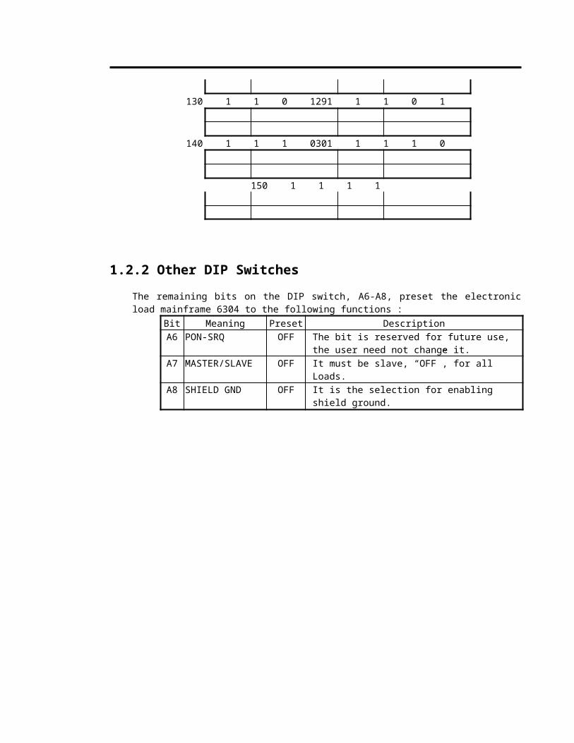
1.2.2 Other DIP Switches
The remaining bits on the DIP switch, A6-A8, preset the electronic load mainframe 6304 to the following functions :
Bit Meaning Preset DescriptionA6 PON-SRQ OFF The bit is reserved for future use, the user need not
change it.A7 MASTER/SLAVE OFF It must be slave, “OFF”, for all Loads.A8 SHIELD GND OFF It is the selection for enabling shield ground.
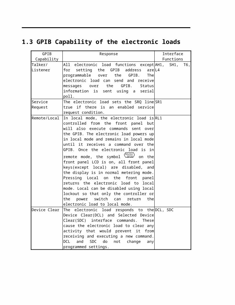
1.3 GPIB Capability of the electronic loads
GPIB Capability Response Interface FunctionsTalker/Listener All electronic load functions except for setting the GPIB
address are programmable over the GPIB. The electronic load can send and receive messages over the GPIB. Status information is sent using a serial poll.
AH1, SH1, T6, L4
Service Request The electronic load sets the SRQ line true if there is an enabled service request condition.
SR1
Remote/Local In local mode, the electronic load is controlled from the front panel but will also execute commands sent over the GPIB. The electronic load powers up in local mode and remains in local mode until it receives a command over the GPIB. Once the electronic load is in remote mode,
the symbol RS232 GPIB on the front panel LCD is on, all front
panel keys(except local) are disabled, and the display is in normal metering mode. Pressing Local on the front panel returns the electronic load to local mode. Local can be disabled using local lockout so that only the controller or the power switch can return the electronic load to local mode.
RL1
Device Clear The electronic load responds to the Device Clear(DCL) and Selected Device Clear(SDC) interface commands. These cause the electronic load to clear any activity that would prevent it from receiving and executing a new command. DCL and SDC do not change any programmed settings.
DCL, SDC
Chapter 2
Introduction to Programming
2.1 Basic Definition
GPIB statement includes instrument control and query commands. A command statement sends an instruction to the electronic load and a query command requests information from the electronic load.
Simple Command
The simplest command statement consists of a command, or keyword, usually followed by a parameter or data:LOAD ONor TRIG
Compound CommandWhen two or more keywords are connected by colons(:), it creates a compound command statement. The last keyword usually is followed by a parameter or data:CURRent : A 3or CONDition : VOLTage : RANGe H
Query CommandA simple query command consists of a keyword followed by a question mark:
VOLT?CURR?
or CHAN?Forms of Keywords
Every keyword has two forms:Long-Form The word is spelled out completely to identify its function. For
instance, CURRENT, VOLTAGE, and TRIGGER are long-form keywords.
Short-Form The word contains only the first three or four letters of the long-form. For instance, CURR, VOLT, and TRIG are short-form keywords.
In keyword definitions and diagrams in this guide, the short-form part of each keyword is emphasized in UPPER-CASE letters to help the user remember it. However, The electronic load will accept Volt, volt, voltage, VOLTAGE, volTAGE, etc. regardless of which form the user applies. If the keywords is incompletely, for example, “VOL” or “curre”, it will not be recognized.
2-1

Introduction to Programming
2.2 Numerical Data Formats
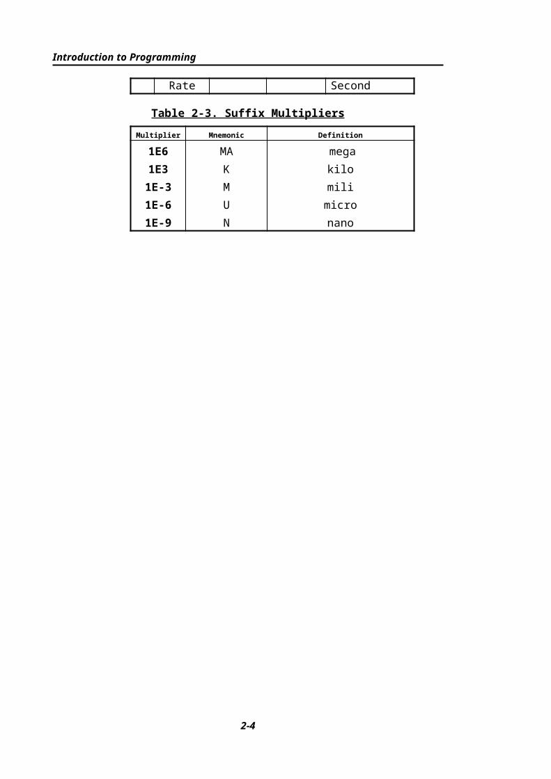
The Chroma 6300 electronic load accepts the numerical data type listed in Table 2-1. Numeric data may be followed by a suffix that dimensions the data. A suffix may be preceded by multiplier. The Chroma 6300 makes use of the suffixes listed in Table 2-2 and multipliers listed in Table 2-3.
Table 2-1. Numerical Data Type
Symbol Description Example
NR1 Digits with no decimal point. The decimal point is assumed to be to the right of the least-significant digit.
123, 0123
NR2 Digits with a decimal point. 123., 12.3, 0.123, .123NR3 Digit with a decimal point and a exponent. 1.23E+3, 1.23E-3NRf Flexible decimal form that includes NR1 or NR2 or NR3. 123, 12.3, 1.23E+3
NRf+ Expanded decimal form that includes NRf and MIN, MAX. MIN and MAX are the minimum and maximum limit values for the parameter.
123, 12.3, 1.23E+3, MIN, MAX
Table 2-2. Suffix ElementsMode Class Preferred Suffix Secondary Suffix Referenced Unit
CC Current A AmpereCR Resistance OHM
MOHMOhmMegohm
CV Amplitude V VoltCP Power W WattAll Frequency HZ
MHZHertzMegahertz
All Time S SecondMS Minisecond
All Slew Rate A/s Amperes/Second
Table 2-3. Suffix Multipliers
Multiplier Mnemonic Definition
1E6 MA mega1E3 K kilo1E-3 M mili1E-6 U micro1E-9 N nano
2-2

Introduction to Programming
2.3 Character Data Formats
For command statements, the <NRf+> data format permits entry of required characters. For query statements, character strings may be returned in either of the forms shown in the following Table, depending on the length of the returned string.
SymbolCharacter Form
crdCharacter Response Data. Permits the return of up to 12 characters.
aardArbitrary ASCII Response Data. Permits the return of undelimited 7-bit ASCII. This data type is an implied message terminator (refer to “Separators and Terminators”).
2.4 Separators and TerminatorsIn addition to keywords and parameters, GPIB program statements require the following :
Data Separators:Data must be separated from the previous command keyword by a space. This is shown in examples as a space (CURR 3) and on diagrams by the letters SP inside a circle.
Keyword Separators: Keywords (or headers) are separated by a colon (:), a semicolon(;), or both. For example :
Ÿ LOAD:SHOR ONŸ MEAS:CURR?;POW?Ÿ CURR:A 16;:VOLT:A 15
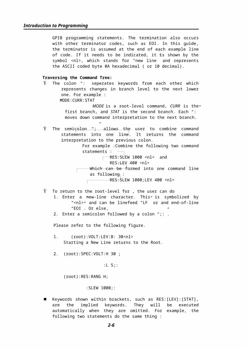
Program Line Separators: A terminator informs GPIB that it has reached the end of a statement. Normally, this is sent automatically by your GPIB programming statements. The termination also occurs with other terminator codes, such as EOI. In this guide, the terminator is assumed at the end of each example line of code. If it needs to be indicated, it is shown by the symbol <nl>, which stands for “new line” and represents the ASCII coded byte 0A hexadecimal ( or 10 decimal).
Traversing the Command Tree:Ÿ The colon “:” seperates keywords from each other which represents changes in branch
level to the next lower one. For example :MODE:CURR:STAT
MODE is a root-level command, CURR is the first branch, and STAT is the second branch. Each “:” moves down command interpretation to the next branch.
2-3

Introduction to Programming
Ÿ The semicolon “;” allows the user to combine command statements into one line. It returns the command interpretation to the previous colon.
For example :Combine the following two command statements :RES:SLEW 1000 <nl> andRES:LEV 400 <nl>
Which can be formed into one command line as following :RES:SLEW 1000;LEV 400 <nl>
Ÿ To return to the root-level for , the user can do1. Enter a new-line character. This is symbolized by “<nl>” and can be linefeed
“LF” or and end-of-line “EOI”. Or else,2. Enter a semicolon followed by a colon “;:”.
Please refer to the following figure.
1. (root):VOLT:LEV:B: 30<nl>Starting a New Line returns to the Root.
2. (root):SPEC:VOLT:H 30 ;
:L 5;:
(root):RES:RANG H;
:SLEW 1000;:
n Keywords shown within brackets, such as RES:[LEV]:[STAT], are the implied keywords. They will be executed automatically when they are omitted. For example, the following two statements do the same thing :
RES:LEV 30RES 30
Under most cases, implied keywords are omitted as the above example. Sometimes the user may use them in order to make the semicolon move the branch level in the desired way. For example,
RES 4:SLEW 50 is an incorrect positioning.This statement can be corrected in the following way :
RES LEV 4;SLEW 50or
RES 4;RES:SLEW 50
2-4
Chapter 3
Language DictionaryCommands for operating the 6300 Electronic Load remotely are grouped into sub-systems. Each command belonging to the same sub-system is arranged in alphabetic order. A syntax chart of the sub-system is given leading the commands belonging to the same group. Sub-systems are then ordered alphabetically according to their names in the following sections.
3.1 COMMON COMMANDSCommon commands defined by the IEEE488.2 standard are generic commands and queries. The first part of the language dictionary covers these commands. Each of them has a leading “*”.
3-1

Language Dictionary
<aard>
<NR1>
<NR1>
<NR1>
<NR1>
<NRf>
<NRf>
<NRf>
<NRf>
SP
SP
SP
SP
*STB?
*SRE?
*SAV
*SRE
*RST
*RCL
*IDN?
*ESR?
*ESE?
*ESE
*CLS
;
*CLS Clear Status CommandType : Device StatusDescription : The *CLS command executes the following actions :
1. Clear these registers<1> Channel Status Event registers for all channels<2> Channel Summary Event register<3> Questionable Status Event register<4> Standard Event Status Event register<5> Operation Status Event register
2. Clear the Error Queue3. If “Clear Status Command” immediately follows a program message
terminator (<nl>), then the “Output Queue” and the MAV bit are also cleared.
3-2
Language Dictionary
Syntax : *CLSParameters : nil
*ESE Standard Event Status Enable Command/QueryType : Device StatusDescription :This command sets the condition of the Standard Event Status Enable register, which
determines which events of the Standard Event Status Event register (see *ESR?¡are allowed to set the ESB (Event Summary Bit) of the Status Byte register. A "1" in the bit position enable the corresponding event. All of the enable events of the Standard Event Status Event register are logically ORed to cause the ESB (bit 5) of the Status Byte register to be set. See Chapter 4 - Status Reporting for description of all three register.
Syntax : ESE <NRf>Parameters : 0 to 255Example : *ESE 48 This command enables the CME and EXE events of the Standard
Event Status Event registerQuery Syntax : *ESE?Return Parameters : <NR1>Query Example : *ESE? This query returns current setting of "Standard Event Status
Enable".
*ESR? Standard Event Status register QueryType : Device StatusDescription :This query reads the Standard Event Status register. Reading the register clears it. See
Chapter 4 - Status Reporting detailed explanation of this register. Standard Event Status Event register
Bit Position 7 6 5 4 3 2 1 0Condition 0 0 CME EXE DDE QYE 0 0Bit Weight 128 64 32 16 8 4 2 1
Query Syntax : *ESR?Return Parameters : <NR1>Query Example : *ESR? returns status readings of Standard Event Status register.Return Example : 48
*IDN? Identification QueryType : System InterfaceDescription :This query requests the Electronic Frame (6304) to identify itself.Query Syntax : *IDN?Return Parameters : <aard>Query Example : *IDN?
String InformationCHROMA Manufacture 6304 Model
0 Always return zero c.xx.xx Revision level of the primary interference firmware
Return Example : CHROMA ATE,6304,0,C,3.04
*RCL Recall Instrument State Command
3-3

Language Dictionary
Type : Device StatusDescription : This command restore the electronic load to a state that was previously stored in
memory with the *SAV command to the specified location (see *SAV ).Syntax : *RCL <NRf>Parameters : 0 to 99Example : *RCL 50
*SAV Save CommandType : Device StatusDescription : This command stores the present state of the single electronic load and the states of
all channels of the multiple load in a specified location in memory.Syntax : *SAV <NRf>Parameters : 0 to 99Example : *SAV 50
*SRE Service Request Enable Command/QueryType : Device StatusDescription : This command sets the condition of the Service Request Enable register,
which determines which events of the Status Byte register (see *STB) are allowed to set the MSS( Master Status Summary) bit. A "1" in the bit position enable bits are logically ORed to cause Bit 6( the Master Summary Status Bit ) of the Status Byte register to be set. See "Chapter 4 - Status Reporting" for more detail concerning the Status Byte register.
Syntax : *SRE <NRf>Parameters : 0 to 255Example : *SRE 20 Enable the CSUM and MAV bit of the Service Request EnableQuery Syntax : *SRE?Return Parameters : <NR1>Query Example : *SRE? Returns current setting for "Service Request Enable"
*STB? Read Status Byte QueryType : Device StatusDescription : This query reads the Status Byte register. Note that the MSS (Master Summary
Status) bit and not the RQS bit is return in Bit 6. This bit indicates whether or the electronic load has at least one reason for requesting service. *STB? does not clear the Status Byte register, which is cleared only whensubsequent action has cleared all its set bits. Refer to "Chapter 4 - Status Reporting" for more information about this register.
Status Byte registerBit Position 7 6 5 4 3 2 1 0Condition 0 MSS ESB MAV QUES CSUM 0 0Bit Weight 128 64 32 16 8 4 2 1
Query Syntax : *STB?Return Parameters : <NR1>Query Example : *STB? Returns contents of "Status Byte"Return Example : 20
3-4

Language Dictionary
3.2 SPECIFIC COMMANDS The 6300 series products equipped with the following specific GPIB commands.
3.2.1 ABORT sub-system
:ABORt
ABORtType : All ChannelApplies to : 63030, 63025, 63010, 63006Description : Set all electronic loads to be "OFF"Syntax : ABORt
3.2.2 CHANNEL sub-system
<NR1>
MAX
MIN
<NRf+>
sp
?
sp:LOAD:CHANnel
CHANnal:[LOAD]Type : Channel IndependentApplies to : 6304Description : To Select a specific channel by which the coming channel-specific command
will be received and executed.Syntax : CHANnel <NRf+>Parameters : 1 ~ 4Example : CHAN 1 sets specific channel as "1"
CHAN MAX sets specific channel as "4"CHAN MIN sets specific channel as "1"
Query Syntax : CHAN?CHAN? MAXCHAN? MIN
Return Parameters : <NR1>Query Example : CHAN? returns current specific channel
CHAN? MAX returns maximum specific channel CHAN? MIN returns minimum specific channel
3-5

Language Dictionary
Return Example : 3
3-6
Language Dictionary
3.2.3 CONDITION sub-system
<NR2>
:OFF
<CHAR>
<aard>
<NR2>
<NRf>
OFF/0
OFF/0
ON/1
<NRf>
ON/1
OFF/0
ON/1
OFF/0
ON/1
DC
AC
sp
sp
sp
sp
sp
sp
?
sp
:HOLD
:AND
:IMMediate
:OR
:OUTPut
:TIMing
:SPECical
:VINSw
:VINType
<NRf>sp:SYNCsource:CHANnel
?
?
suffix
L
H
<NRf>sp
<NRf> suffixsp
:RANGe
:B
:A
:ON
:VOLTage:CONDition
CONDition:VOLTage:ONType : Channel-Specific
3-7

Language Dictionary
Applies to : 63030, 63025, 63010, 63006Description : Set Voltage of Sink Current On.Syntax : CONDition:VOLTage:ON <NRf> [suffix]Parameters : For valid voltage range, refer to respective specification.Example : COND:VOLT:ON 1 sets Von=1V.
COND:VOLT:ON 300mV sets Von=300mV.Query Syntax : CONDition:VOLTage:ON?Return Parameters : <NR2> [Unit=Voltage]Query Example : COND:VOLT:ON? returns setting Von value.Return Example : 3.5
CONDition:VOLTage:AType : Channel-SpecificApplies to : 63030, 63025, 63010, 63006, 6305Description : Set voltage value of point A for Timing MeasurementSyntax : CONDition:VOLTage:A <NRf> [suffix]Parameters : For valid value range, refer to respective specification.Example : COND:VOLT:A 2 set that value as 2V.
COND:VOLT:A 300E-3 set that value as 300mV.Query Syntax : CONDition:VOLTage:A?Return Parameters : <NR2> [Unit :Voltage]Query Example : COND:VOLT:A? returns the setting voltage value of point A
for timing measurement.
CONDition:VOLTage:BType : Channel-SpecificApplies to : 63030, 63025, 63010, 63006, 6305Description : Set voltage value of point B for Timing Measurement.Syntax : CONDition:VOLTage:B <NRf> [suffix]Parameters : For valid value range, refer to respective specification.Example : COND:VOLT:B 2 sets that value as 2V.
COND:VOLT:B 300E-3 sets that value as 300mV.Query Syntax : CONDition:VOLTage:B?Return Parameters : <NR2> [Unit=Voltage]Query Example : COND:VOLT:B? returns setting voltage value of point B for
timing measurement.Return Example : 5.25
CONDition:VOLTage:RANGeType : Channel-SpecificApplies to : 63030, 63025, 63010, 63006Description : Set full-range for voltage measurement.Syntax : CONDition:VOLTage:RANGEe <NRf> [suffix]Parameters : value ranges depend on Load Module. For details, refer to specificationExample : COND:VOLT:RANG 5 sets full-range as Low, for example, in 63030.
COND:VOLT:RANG 30V sets full-range as High, for example, in 63030.
COND:VOLT:RANG H sets full-range as High.COND:VOLT:RANG L sets full-range as Low.
Query Syntax : CONDition:VOLTage:RANGe?Return Parameters : <NR2> [Unit = Voltage]
3-8

Language Dictionary
Query Example : COND:VOLT:RANG? returns Voltage rangeReturn Example : 16
CONDition:CHANnel:SYNCsourceType : Channel IndependentApplies to : 6304Description : Set channel number as to match with the 6305 for timing measurement.Syntax : CONDition:CHANnel:SYNCsouce <NRf>Parameters : 1 ~ 4Example : COND:CHAN:SYNC 1 sets it while the 6305 locates at channel No. 1.
CONDition:VINTypeType : Channel-SpecificApplies to : 6305Description : Set which type for voltage input.Syntax : CONDition:VINTypeParameters : AC, DCExample : COND:VINT AC sets voltage input as AC.
COND:VINT DC sets voltage input as DC.Query Syntax : CONDition:VINType?Return Parameters : <CHAR>Query Example : COND:VINT?returns input voltage type. Return Example : AC
CONDition:VINSwType : Channel-SpecificApplies to : 6305Description : Set the switch for inputs connected to output terminals.Syntax : CONDition:VINSwParameters : ON, OFFExample : COND:VINS ON sets “ON” connection of input to output. COND:VINS OFF sets “OFF” connection of input to output.
CONDition:SPECicalType : Channel-SpecificApplies to : 6305Description : To set output voltage trigger condition.Syntax : CONDition:SPECical ON
CONDition:SPECical OFFParameters : ON, OFFExample : COND:SPEC ON sets output trigger by “EXTA” or “EXTB”. COND:SPEC OFF sets output trigger by “AC” or “DC”.
CONDition:TIMingType : All Channel Applies to : 63030, 63025, 63010, 63006, 6305Description : Switching On or Off the Timing Measure function.Syntax : CONDition:TIMing ON
CONDition:TIMing OFF
3-9

Language Dictionary
Parameters : ON, OFFExample : COND:TIM ON sets Timing Measurement ON.
COND:TIM OFF sets Timing Measurement OFF.
CONDition:OUTPutType : Channel-SpecificApplies to : 6305, 6307Description : Set output condition of the output port which is stored in the 8-BIT register.Syntax : CONDition:OUTPut <NRf>
CONDition:OUTPut:IMMediate <NRf>CONDition:OUTPut:AND <NRf>CONDition:OUTPut:OR <NRf>
Parameters : 0 ~ 255Example : CONDition:OUTPut 24 sets the output register as “24” in
order that output enables while triggered.
CONDition:OUTPut:IMMediate 33 sets the output register as “33” in order that output enables immediately.
CONDition:OUTPut:AND 40 sets the output register to be value of the T-output port ANDed with “40”; the output enables while triggered, and the output register is not changed.
CONDition:OUTPut:OR 56 sets the output register to be value of the T-ouput port ORed with “56”; the output enables while triggered, and the output register is not changed.
CONDition:HOLDType : Channel-SpecificApplies to : 63030, 63025, 63010, 63006Description : This command sets the way received data are held.Syntax : CONDition:HOLD ON
CONDition:HOLD OFFParameters : ON, OFFExample : COND:HOLD ON sets to hold received data on registered data buffer.
COND:HOLD OFF sets to copy data from registered data buffer to working data buffer.
3-10

Language Dictionary
3.2.4 CURRENT sub-system
<NR2>
<NR2>
<NR2>
<NR2>
<NR2>
:CURRent
MAX
MIN
suffix<NRf+>
sp
?
sp
:T2
:T1:TIME
MAX
MIN
suffix<NRf+>
sp
?
sp
:FALL:DYNamic
:RISE:STATic:SLEW
MAX
MIN
suffix
L
H
<NRf+>
sp
?
sp:RANGe
spMAX
MIN
suffix<NRf+>
?
sp
:L
:H:DYNamic
MAX
MINsp
?:B
suffix<NRf+>sp:A:STATic:LEVel
CURRent:[LEVel]:[STATic]Type : Channel-SpecificApplies to : 63030, 63025, 63010, 63006Description : Set Static Load Current during constant current mode.Syntax : CURRent:[LEVel]:[STATic]:A <NRf+> [suffix]
CURRent:[LEVel]:[STATic]:B <NRf+> [suffix]Parameters : For valid value range, refer to respective specification
3-11

Language Dictionary
Example : CURR:A 20 sets Constant Current = 20A for Static Load A. CURR:B 10A sets Constant Current = 10A for Static Load B.
CURR:A MAX sets Constant Current = maximum value for Static Load A.
CURR:B MIN sets Constant Current = minimum value for Static Load B.
Query Syntax : CURRent:[LEVel]:[STATic]:A? CURRent:[LEVel]:[STATic]:B? CURRent:[LEVel]:[STATic]:A? MAX
CURRent:[LEVel]:[STATic]:B? MINReturn Parameters : <NR2> [Unit : Ampere]Query Example : CURR:A? returns setting current value of the Static Load A.
CURR:B? returns setting current value of the Static Load B.CURR:A? MAX returns the maximum programmable current value of
the Static Load A.CURR:B? MIN returns the minimum programmable current value of
the Static Load B.Return Example : 3.12
CURRent:[LEVel]:[DYNamic]Type : Channel-SpecificApplies to : 63030, 63025, 63010, 63006Description : Set Dynamic Load Current during constant current mode.Syntax : CURRent:[LEVel]:[DYNamic]:H <NRf+> [suffix]
CURRent:[LEVel]:[DYNamic]:L <NRf+> [suffix]Parameters : For valid value range, refer to respective specification.Example : CURR:H 20 sets dynamic load parameter H=20A.
CURR:L 10A sets dynamic load parameter L=10A.CURR:H MAX sets dynamic load parameter H=maximum value.CURR:L MIN sets dynamic load parameter L=minimum value.
Query Syntax : CURRent:[LEVel]:[DYNamic]:H? CURRent:[LEVel]:[DYNamic]:L? CURRent:[LEVel]:[DYNamic]:H? MAX CURRent:[LEVel]:[DYNamic]:L? MINReturn Parameters : <NR2> [Unit=Ampere]Query Example : CURR:H? returns setting current in dynamic load H.
CURR:L? returns setting current in dynamic load L.CURR:H? MAX returns maximum current under present full-range for
dynamic load H.CURR:L? MIN returns minimum VALUE current under present full-
range for dynamic load L.Return Example : 35.6
CURRent:RANGeType : Channel-SpecificApplies to : 63030, 63025, 63010, 63006Description : Select the full-range of current range during constant current mode.Syntax : CURRent:RANGe <NRf+> [suffix]Parameters : For valid value range, refer to respective specification.Example : CURR:RANG 6A sets full-range of current as 6A. (It is the lower
scale in 63030, for instance.)
3-12
Language Dictionary
CURR:RANG MAX sets full-range of current as the higher.CURR:RANG MIN sets full-range of current as the lower.
Query Syntax : CURRent:RANGe?CURRent:RANGe? MAXCURRent:RANGe? MIN
Return Parameters : <NR2> [Unit=Ampere]Query Example : CURR:RANG? returns the present full-range current range.
CURR:RANG? MAX returns the maximum programmable current range.
CURR:RANG? MIN returns the mininum programmable current range.Return Example : 6
CURRent:SLEWType : Channel-SpecificApplies to : 63030, 63025, 63010, 63006Description : Set Current Slew rate during constant Current modeSyntax : CURRent:SLEW:STATic:RISE <NRf+> [suffix]
CURRent:SLEW:STATic:FALL <NRf+> [suffix] CURRent:SLEW:DYNamic:RISE <NRf+> [suffix] CURRent:SLEW:DYNamic:FALL <NRf+> [suffix]
Parameters : For valid value range, refer to respective specification.Example : CURR:SLEW:STAT:RISE 2.5 sets rise slew rate as
2.5A/uS of static load. CURR:SLEW:STAT:FALL 1A/uS sets fall slew rate as 1A/uS of
static load. CURR:SLEW:DYN:RISE MAX sets rise slew rate as
maximum valueof dynamic load.
CURR:SLEW:DYN:FALL MIN sets fall slew rate as minimum value of dynamic load.
Query Syntax : CURRent:SLEW:STATic:RISE?CURRent:SLEW:STATic:FALL? MAXCURRent:SLEW:DYNamic:RISE?CURRent:SLEW:DYNamic:FALL? MIN
Return Parameters : <NR2> [Unit=A/uS]Query Example : CURR:SLEW:STAT:RISE? returns rise slew rate of static load.
CURR:SLEW:STAT:RISE? MAX returns programmable rise slew rate of the maximum for static load.
CURR:SLEW:DYN:FALL? returns fall slew rate of dynamic load.
CURR:SLEW:DYN:FALL? MIN returns programmable fall slew rate of the minimum for dynamic load.
Return Example : 2.5
CURRent:TIMEType : Channel-SpecificApplies to : 63030, 63025, 63010, 63006Description : Set the duration parameter T1, or T2 of dynamic load.Syntax : CURRent:TIME:T1 <NRf+> [suffix]
CURRent:TIME:T2 <NRf+> [suffix]
3-13
Language Dictionary
Parameters : For valid value range, refer to respective specification.Example : CURRent:TIME:T1 10mS sets duration T1=10mS.
CURRent:TIME:T2 2S sets duration T1=2S.CURRent:TIME:T1 MAX sets duration T1 as the maximum value.
CURRent:TIME:T2 MIN sets duration T2 as the minimum value.Query Syntax : CURRent:TIME:T1?
CURRent:TIME:T1? MAXCURRent:TIME:T2? MIN
Return Parameters : <NR2> [Unit=Sec]Query Example : CURR:TIME:T1? returns the present duration parameter
T1. CURR:TIME:T1? MAX returns the maximum programmable
duration parameter T1.CURR:TIME:T2? MIN returns the minimum programmable
duration parameter T2.Return Example : 0.15
3-14

Language Dictionary
3.2.5 IDENTIFICATION sub-system
<aard>?:ID
ID?Type : Channel-SpecificDescription : This query requests the module to identify itself.Query Syntax : ID?Return Parameters : <aard>Query Example : ID?
String InformationCHROMA Manufacturer63030 Model0 Always return zeroc.xx.xx Revision of the primary interface firmware
Return Example : CHROMA,63030,0,C.3.04
3-15

Language Dictionary
3.2.6 INPUT sub-system
<NR2>
suffix<NRf>
?
sp:LIMit:INPut :CURRent
INPut:[CURRent]:LIMitType : Channel-SpecificApplies to : 6305
Description : Set or Return the limitation of input current.Syntax : INPut:[CURRent]:LIMit <NRf> [suffix]Parameters : For valid value range, refer to respective specification.Example : INP:LIM 30A sets the input current limit as 30A.Query Syntax : INPut:[CURRent]:LIMit?Return Parameters : <NR2> [Unit=Ampere]Query Example : INP:LIM? returns the present input current limit.Return Example : 80
3-16

Language Dictionary
3.2.7 LOAD sub-system
<NR1>
<NR1>
?
sp
sp
?
OFF/0
ON/1
OFF/0
ON/1:STATe:SHORt
:STATe:LOAD
LOAD:[STATe]
Type : Channel-SpecificApplies to : 63030, 63025, 63010, 63006Description : The LOAD command makes the electronic load active or inactive.Syntax : LOAD:[STATe] ON
LOAD:[STATe] OFFParameters : ON, OFFExample : LOAD ON activates the electronic load. LOAD OFF inactivates the electronic load.Query Syntax : LOAD:[STATe]?Return Parameters : <NR1>Query Example : LOAD? returns if the electronic load is active.Return Example : 1
LOAD:SHORt:[STATe]Type : Channel-SpecificApplies to : 63030, 63025, 63010, 63006Description : To activate or inactivate short-circuited simulation.Syntax : LOAD:SHORt:[STATe]Example : LOAD:SHOR ON activates short-circuited simulation.
LOAD:SHOR OFF inactivates short-circuited simulation.Parameters : ON, OFFQuery Syntax : LOAD:SHORt:[STATe]?Return Parameters : <NR1>Query Example : LOAD:SHOR? returns if the short-circuited simu-
lation is active.Return Example : 1
3-17

Language Dictionary
3.2.8 MEASURE sub-system
3-18

Language Dictionary
<NR2>
<NR2>
<NR2>
<NR2>
<NR2>
<NR2>
<aard>
<NR2>
<NR2>
<NR2>
<NR2>
?
?
?
<NRf>sp
?
?
?
?
?
?
?
:VPKLow
:VPKHigh
:PORT
:FREQency
:EXTTiming
:VPRe
:ITRip
:RING
:TIMing
sp
?
LOAD
UUT:INPut
:NOISe
:AC
?
?
?
?
:DC
:POWer
:VOLTage
:DC
:DC:CURRent:MEASure
:BATTtiming
3-19
Language Dictionary
MEASure:CURRent:[DC]?Type : Channel-SpecificApplies to : 63030, 63025, 63010, 63006Description : To return current measured at the input of the electronic load.Query Syntax : MEASure:CURRent:[DC]?Return Parameters : <NR2> [Unit=Ampere]Query Example : MEAS:CURR? returns present loading current.Return Example : 3.15
MEASure:POWer:[DC]?Type : Channel-SpecificApplies to : 63030, 63025, 63010, 63006Description : To return power measured at the input of the electronic load.Query Syntax : MEASure:POWer:[DC]?Return Parameters : <NR2> [Unit=Watt]Query Example : MEAS:POW? returns present power dissipation.
MEASure:VOLTage:[DC]?Type : Channel-SpecificApplies to : 63030, 63025, 63010, 63006, 6308Description : This function returns DC voltage measured at the input of the electronic load.Query Syntax : MEASure:VOLTage:[DC]?Return Parameters : <NR2> [Unit=Voltage]Query Example : MEAS:VOLT? returns present input DC voltage.Return Example : 8.12
MEASure:VOLTage:[DC]Type : Channel-SpecificApplies to : 6308Description : This funtion initiates measuring input DC voltage.Syntax : MEASure:VOLTage:[DC]Parameters : nilExample : MEAS:VOLT returns present input DC voltage.
MEASure:VOLTage:ACType : Channel-SpecificApplies to : 6308Description : This function initiates measuring input AC voltage.Syntax : MEASure:VOLTage:ACParameters : nilExample : MEAS:VOLT:AC initiates measuring input AC voltage.Query Syntax : MEASure:VOLTage:AC?Return Parameters : <NR2> [Unit=Voltage]Query Example : MEAS:VOLT:AC? returns present input AC voltage.Return Example : 12
MEASure:NOISe?Type : Channel-SpecificApplies to : 63030, 63025, 63010, 63006Description : This function returns NOISE voltage level at the input of the electronic load.
3-20

Language Dictionary
Query Syntax : MEASure:NOISe?Return Parameters : <NR2> [Unit=Voltage]Example : MEAS:NOIS? returns the NOISE measurement
readings.Return Example : 0.05
MEASure:INPutType : Channel-SpecificApplies to : 63030, 63025, 63010, 63006Description : To select which ends the electronic load measures voltages.Syntax : MEASure:INPut:UUT
MEASure:INPut LOADParameters : UUT, LOADExample : MEAS:INP:UUT
MEAS:INP:LOADQuery Syntax : MEASure:INPut?Return Parameters : <CHAR>Query Example : MEAS:INP? returns which ends it measures.Return Example : UUT
MEASure:TIMing?Type : Channel-SpecificApplies to : 63030, 63025, 63010, 63006Description : This command returns Timing Measurement reading.Query Syntax : MEASure:TIMing?Return Parameters : <NR2> [Unit=mSec]Example : MEAS:TIM? returns Timing Measurement reading.Return Example : 0.125
MEASure:RING?Type : Channel-SpecificApplies to : 6305Description : This command returns Ring times of the PG(POWER GOOD) signal.Query Syntax : MEASure:RING?Return Parameters : <NR2>Example : MEAS:RING? returns Ring times of the PG (POWER GOOD) signal.Return Example : 2
MEASure:ITRip?Type : Channel-SpecificApplies to : 63030, 63025, 63010, 63006Description : This command returns setting current value during constant current mode for
Timing Measurement.Query Syntax : MEASure:ITRip?Return Parameters : <NR2> [Unit=Ampere]Example : MEAS:ITR? returns setting current during constant current mode.Return Example : 5.12
MEASure:VPRe?
3-21

Language Dictionary
Type : Channel-SpecificApplies to : 63030, 63025, 63010, 63006Description : This command returns voltage measurement reading at the last TRIG:NEXT
command during Timing Measurement.Query Syntax : MEASure:VPRe?Return Parameters : <NR2> [Unit=Voltage]Example : MEAS:VPR? returns voltage reading when the last TRIG:NEXT
command executes.Return Example : 12.45
MEASure:EXTT?Type : Channel-SpecificApplies to : 6305Description : This function returns duration between trigger to EXT-A or EXT-B.Query Syntax : MEASure:EXTT?Return Parameters : <NR2> [Unit=mSec]Example : MEAS:EXTT? returns timing measurement value of EXT-A, EXT-B.Return Example : 1.345
MEASure:FREQuencyType : Channel-SpecificApplies to : 6308Description : This command initiates frequency measurement.Syntax : MEASure:FREQuencyParameters : nilExample : MEAS:FREQ initiates frequency measurement.Query Syntax : MEASure:FREQuency?Return Parameters : <NR2> [Unit=Hz]Query Example : MEAS:FREQ? returns frequency readings.Return Example : 100.45
MEASure:PORTType : Channel-SpecificApplies to : 6308Description : This function sets the input port of measurement.Syntax : MEASure:PORTParameters : 0 ~ 10Example : MEAS:PORT 4 sets the input port as number 4.
MEASure:VPKHighType : Channel-SpecificApplies to : 63030, 63025, 63010, 63006 Description : The test of dynamic load, and the measurement of VPK+. Query Syntax : MEASure:VPKHigh?Parameters : nilExample : MEAS:VPKHReturn Example : 10.2
MEASure:VPKLow
3-22

Language Dictionary
Type : Channel-SpecificApplies to : 63030, 63025, 63010, 63006 Description : The test of dynamic load, and the measurement of VPK-. Query Syntax : MEASure:VPKLow?Parameters : nilExample : MEAS:VPKLReturn Example : 10.2
MEASure:BATTtiming
Type : Channel-SpecificApplies to : 63030, 63025, 63010, 63006 Description : The measurement of the time of battery charge.Query Syntax : MEASure:BATTtiming?Parameters : nilExample : MEAS:BATTReturn Example : 1000
3-23

Language Dictionary
3.2.9 MODE sub-system
<aard>?
:POWer
:DYNamic
:STATic
:VOLTage
:DYNamic
:EXTernal
:B
:B
:B
:A
:A
:A
:A
:B
:STATic:CURRent
:RESistance
:MODE
MODE:CURRent
Type : Channel-SpecificApplies to : 63030, 63025, 63010, 63006Description : This command sets constant current mode for each operation.Syntax : MODE:CURRent[:STATic]:A
MODE:CURRent[:STATic]:BMODE:CURRent:EXTernalMODE:CURRent:DYNamic
Parameters : nilExample : MODE:CURR:A sets constant current mode for Static Load A.
MODE:CURR:B sets constant current mode for Static Load B. MODE:CURR:EXT sets constant current mode for Load sinked by External
signal.MODE:CURR:DYN sets constant current mode for Dynamic
Load.
3-24

Language Dictionary
MODE:RESistanceType : Channel-SpecificApplies to : 63030, 63025, 63010, 63006Description : This command sets constant resistance mode for each operation.Syntax : MODE:RESistance[:STATic]:A
MODE:RESistance[:STATic]:BMODE:RESistance:DYNamic
Parameters : nilExample : MODE:RES:A sets constant resistance mode for Static Load A.
MODE:RES:B sets constant resistance mode for Static Load B.MODE:RES:DYN sets constant resistance mode for Dynamic Load.
MODE:VOLTageType : Channel-SpecificApplies to : 63030, 63025, 63010, 63006Description : This command sets constant voltage mode for each operation.Syntax : MODE:VOLTage:A
MODE:VOLTage:BParameters : nilExample : MODE:VOLT:A sets constant voltage mode for Static Load A.
MODE:VOLT:B sets constant voltage mode for Static Load B.
MODE:POWerType : Channel-SpecificApplies to : 63030, 63025, 63010, 63006Description : This command sets constant power mode for each operation.Syntax : MODE:POWer:A
MODE:POWer:BParameters : nilExample : MODE:POW:A sets constant power mode for Static Load A.
MODE:POW:B sets constant power mode for Static Load B.
MODE?Type : Channel-SpecificApplies to : 63030, 63025, 63010, 63006Description : This function returns operational modes of the electronic load.Query Syntax : MODE?Return Parameters : <aard>Query Example : MODE? returns the operational modes.Return Example : CURR,A,H returns constant current mode static A high
range.CURR,B,L returns constant current mode static A low range.CURR,D,H returns constant current mode dynamic high range.
CURR,E,L returns constant current mode dynamic low range.
3-25

Language Dictionary
3.2.10 NOISE sub-system
<NR1>
<NR1>
sp
?
sp
sp
?
MAX
MIN
L
H
suffix<NRf+>
suffix<NRf+>
:RANGe
:NOISe :BANDwidth
NOISe:BANDwidthType : Channel-SpecificApplies to : 63030, 63025, 63010, 63006Description : This command sets the Filter of the Noise measurement.Syntax : NOISe:BANDwidth <NRf> [suffix]Parameters : For valid value range, refer to respective specification.Example : NOIS:BAND 1000 sets the filter of the Noise measurement as
1000Hz.NOIS:BAND 10KHz sets the filter of the Noise measurement as
10KHz.NOIS:BAND 100KHz sets the filter of the Noise measurement as
100KHz.NOIS:BAND 1MHz sets the filter of the Noise measurement as
1MHz.NOIS:BAND 20MHz sets the filter of the Noise measurement as
20MHz.Query Syntax : NOISe:BANDwidth?Return Parameters : <NR2> [Unit=Hz]Query Example : NOIS:BAND?Return Example : 1000
NOISe:RANGeType : Channel-SpecificApplies to : 63030, 63025, 63010, 63006Description : This command selects the full-range of the Noise
measurement.Syntax : NOISe:RANGe <NRf+> [suffix]
3-26

Language Dictionary
NOISe:RANGe HNOISe:RANGe L
Parameters : For valid value range, refer to respective specification.Example : NOIS:RANG 0.4 sets the range as the lower.
NOIS:RANG H sets the range as the higher.NOIS:RANG L sets the range as the lower.
Query Syntax : NOISe:RANGe?NOISe:RANGe? MAXNOISe:RANGe? MIN
Return Parameters : <NR2> [Unit=Hz]Query Example : NOIS:RANG?returns present full-range value of the noise measurement.
NOIS:RANG? MAX returns maximum value of the present full-range of the Noise measurement.
NOIS:RANG? MIN returns minimum value of the present full-range of the Noise measurement.
Return Example : 1000
3-27

Language Dictionary
3.2.11 POWER sub-system
<NR2>
<NR2>
<NR2>
:POWer
MAX
MIN
suffix<NRf+>
sp
?
sp
:FALL
:RISE:SLEW
MAX
MIN
suffix
L
H
<NRf+>
sp
?
sp:RANGe
MAX
MINsp
?:B
suffix<NRf+>sp:A:LEVel
POWer:[LEVel]Type : Channel-SpecificApplies to : 63030, 63025, 63010, 63006Description : This command sets the power level of the electronic load during constant
power mode.Syntax : POWer:[LEVel] A <NRf+> [suffix]
POWer:[LEVel] B <NRf+> [suffix]Parameters : For valid value range, refer to respective specification.Example : POW:A 30W
POW:B 100Query Syntax : POWer:[LEVel]:A?
POWer:[LEVel]:B?POWer:[LEVel]:? MAXPOWer:[LEVel]:? MIN
Return Parameters : <NR2> [Unit=Watt]Query Example : POW:A? returns setting power level of the Static A.
POW:B? returns setting power level of the Static B. POW:A? MAX returns maximum programmable power level of the
Static A under present full-range.POW:B? MIN returns minimum programmable power level of the Static B
under present full-range.
3-28
Language Dictionary
Return Example : 15.5
POWer:RANGeType : Channel-SpecificApplies to : 63030, 63025, 63010, 63006Description : This command sets full-range of power during constant power mode.Syntax : POWer:RANGe <NRf+> [suffix]
POWer:RANGe HPOWer:RANGe L
Parameters : For valid value range, refer to respective specification.Example : POW:RANG 30W sets power full-range as the lower for 63030, for
instance.POW:RANG MAX sets power full-range as the higher.POW:RANG MIN sets power full-range as the lower.
Query Syntax : POWer:RANGe?POWer:RANGe? MAXPOWer:RANGe? MIN
Return Parameters : <NR2> [Unit=Watt]Query Example : POW:RANGe? returns value of the power full-range.
POW:RANG? MAX returns maximum programmable value of the present power full-range.
POW:RANG? MIN returns minimum programmable value of the present power full-range.
Return Example : 300
POWer:SLEWType : Channel-SpecificApplies to : 63030, 63025, 63010, 63006Description : This command sets current slew rate during constant power mode.Syntax : POWer:SLEW:RISE <NRf+> [suffix]
POWer:SLEW:FALL <NRf+> [suffix]Parameters : For valid value range, refer to respective specification.Example : POW:SLEW:RISE 2.5 sets rise slew rate as 2.5A/uS.
POW:SLEW:FALL 1A/uS sets fall slew rate as 1A/uS.POW:SLEW:RISE MAX sets rise slew rate as the maximum value.
POW:SLEW:FALL MIN sets fall slew rate as the minimum value.Query Syntax : POWer:SLEW:RISE?
POWer:SLEW:FALL? MAXReturn Parameters : <NR2> [Unit=A/uS]Query Example : POW:SLEW:RISE? returns rise slew rate.
POW:SLEW:RISE? MAX returns maximum programmable value of the rise slew rate.
Return Example : 2.5
3-29

Language Dictionary
3.2.12 PROTECTION sub-system
<NR1>?
:CLEAr:PROTection
PROTection:CLEarType : Channel-SpecificApplies to : 63030, 63025, 63010, 63006Description : This command resets or returns status of the electronic load.Syntax : PROTection:CLEarParameters : For valid value range, refer to respective specification.Example : PROT:CLEQuery Syntax : PROTection:CLEar? Return Parameters : <NR1>Bit Position 15 14 13 12 11 10 9 8 7 6 5 4 3 2 1 0Condition 0 0 0 OV RV 0 0 0 0 0 0 OT OP 0 OC 0Bit Weight 4096 2048 128 16 8 2Query Example : PROT:CLE? returns status of the electronic load.Return Example : 24
3-30

Language Dictionary
3.2.13 RELAY sub-system
<NRf>
<NRf>
sp
sp
:FLOat
:OVP:RELay
RELay:OVPType : Channel-SpecificApplies to : 6307Description : To set OVP relaySyntax : RELay:OVP <NRf>Parameters : 0 ~ 3Example : REL:OVP 3
RELay:FLOatType : Channel-SpecificApplies to : 6307Description : To set FLOAT relaySyntax : RELay:FLOat <NRf>Parameters : 0 ~ 15Example : REL:FLO 12
3-31

Language Dictionary
3.2.14 RESISTANCE sub-system
MAX
<NR2>
:RESistance
<NR2>
<NR2>
<NR2>
<NR2>
MAX
MIN
suffix<NRf+
sp
?
sp
:T
:T:TIME
MIN
suffix<NRf+
sp
?
sp
:FALL:DYNamic
:RISE:STATic:SLEW
MAX
MIN
suffix
L
H
<NRf+
sp
?
sp:RANGe
spMAX
MIN
suffix<NRf+>
?
sp
:L
:H:DYNamic
MAX
MINsp
?:B
suffix<NRf+>
sp:A:STATic:LEVel
RESistance:[LEVel]:[STATic]Type : Channel-SpecificApplies to : 63030, 63025, 63010, 63006Description : This function sets static resistance level during constant
resistance mode.Syntax : RESistance:[LEVel]:[STATic]:A <NRf+>
RESistance:[LEVel]:[STATic]:B <NRf+>
3-32

Language Dictionary
Parameters : For valid value range, refer to respective specification.Example : RES:A 20 OHM sets Static Constant Load Resistance A as 20 ohm.
RES:B 10 OHM sets Static Constant Load Resistance B as 10 ohm.RES:A MAX sets Static Constant Load Resistance A as maximum
value.RES:B MIN sets Static Constant Load Resistance B as minimum
value.Query Syntax : RESistance:[LEVel]:[STATic]:A?
RESistance:[LEVel]:[STATic]:B?RESistance:[LEVel]:[STATic]:A? MAXRESistance:[LEVel]:[STATic]:B? MIN
Return Parameters : <NR2> [Unit=OHM]Query Example : RES:A? returns setting resistance of the Static Load A.
RES:B? returns setting resistance of the Static Load B.RES:A? MAX returns maximum programmable resistance of the Static
A under the present full-range.RES:B? MIN returns minimum programmable resistance of the Static
B under the present full-range.Return Example : 100
RESistance:[LEVel]:[DYNamic]Type : Channel-SpecificApplies to : 63030, 63025, 63010, 63006Description : This function sets the dynamic loading resistance during the constant
resistance mode.Syntax : RESistance:[LEVel]:[DYNamic]:H <NRf+>
RESistance:[LEVel]:[DYNamic]:L <NRf+>Parameters : For valid value range, refer to respective specification.Example : RES:H 20 OHM sets Dynamic Load Resistance H as 20
ohm. RES:L 10 OHM sets Dynamic Load Resistance L as 10
ohm. RES:H MAX sets Dynamic Load Resistance H as maximum value.RES:L MIN sets Dynamic Load Resistance L as minimum value.
Query Syntax : RESistance:[LEVel]:[DYNamic]:H? RESistance:[LEVel]:[DYNamic]:L? RESistance:[LEVel]:[DYNamic]:H? MAX
RESistance:[LEVel]:[DYNamic]:L? MINReturn Parameters : <NR2> [Unit=OHM]Query Example : RES:H? returns setting resistance of Dynamic Load H.
RES:L? returns setting resistance of Dynamic Load L.RES:H? MAX returns the maximum programmable resistance of
Dynamic Load H under present scale.RES:L? MIN returns the minimum programmable resistance of
Dynamic Load L under present scale.Return Example : 10
RESistance:RANGeType : Channel-SpecificApplies to : 63030, 63025, 63010, 63006Description : To select full-range range of resistance during constant resistance mode.
3-33

Language Dictionary
Syntax : RESistance:RANGe <NRf+>Parameters : For valid value range, refer to respective specification.Example : RES:RANG 1 sets resistance full-range as the lower. For
example, the 63030. RES:RANG MAX sets resistance full-range as the higher.RES:RANG MIN sets resistance full-range as the lower.
Query Syntax : RESistance:RANGe?RESistance:RANGe? MAXRESistance:RANGe? MIN
Return Parameters : <NR2> [Unit=OHM]Query Example : RES:RANG? returns resistance full-range.
RES:RANG? MAX returns maximum programmable value of resistance.
RES:RANG? MIN returns minimum programmable value of resistance.
Return Example : 6
RESistance:SLEWType : Channel-SpecificApplies to : 63030, 63025, 63010, 63006Description : This command sets resistive slew rate during constant resistance mode.Syntax : RESistance:SLEW:STATic:RISE <NRf+>
RESistance:SLEW:STATic:FALL <NRf+>RESistance:SLEW:DYNamic:RISE <NRf+>RESistance:SLEW:DYNamic:FALL <NRf+>
Parameters : For valid value range, refer to respective specification.Example : RES:SLEW:STAT:RISE 2.5 sets static resistive rise slew as 2.5A/uS.
RES:SLEW:STAT:FALL 1A/uS sets static resistive fall slew as 1A/uS.RES:SLEW:DYN:RISE MAX sets dynamic resistive rise slew as the
maximum programmable value. RES:SLEW:DYN:FALL MIN sets dynamic resistive fall slew as
the minimum programmable value.
Query Syntax : RESistance:SLEW:STATic:RISE?RESistance:SLEW:STATic:FALL? MAXRESistance:SLEW:DYNamic:RISE?RESistance:SLEW:DYNamic:FALL? MIN
Return Parameters : <NR2> [Unit=A/uS]Query Example : RES:SLEW:STAT:RISE? returns static resistive rise slew rate.
RES:SLEW:STAT:RISE? MAX returns maximum value of static resistive rise slew rate.
RES:SLEW:DYN:FALL? returns dynamic resistive fall slew rate.
RES:SLEW:DYN:FALL? MIN returns minimum value of dynamic resistive fall slew rate.
Return Example : 2.5
RESistance:TIMEType : Channel-Specific
3-34

Language Dictionary
Applies to : 63030, 63025, 63010, 63006Description : This function sets duration parameter T1 or T2 of the Dynamic Load.Syntax : RESistance:TIME:T1 <NRf+>
RESistance:TIME:T2 <NRf+>Parameters : For valid value range, refer to respective specification.Example : RES:TIME:T1 10mS sets the duration T1 as 10mS.
RES:TIME:T2 2S sets the duration T2 as 2S.RES:TIME:T1 MAX sets the duration T1 as the maximum
programmable value.RES:TIME:T2 MIN sets the duration T2 as the minimum
programmable value.Query Syntax : RESistance:TIME:T1?
RESistance:TIME:T1? MAXRESistance:TIME:T2? MIN
Return Parameters : <NR2> [Unit=Sec]Query Example : RES:TIME:T1? returns the setting duration T1.
RES:TIME:T1? MAX returns the maximum programmable value of duration T1.
RES:TIME:T2? MIN returns the minimum programmable value of duration T2.
Return Example : 0.15
3-35

Language Dictionary
3.2.15 RUN sub-system
:OCP
:RUN
RUNType : All ChannelApplies to : 63030, 63025, 63010, 63006Description : This command sets all electronic loads “ON”.Syntax : RUN
RUN:OCPType : All ChannelApplies to : 63030, 63025, 63010, 63006Description : This command sets all electronic loads and timing measurement
“ON”.Syntax : RUN:OCP
3-36

Language Dictionary
3.2.16 SPECIFICATION sub-system
<NR2>:C
sp
?
:L
:H:DYNamic suffix<NRf+>
?
sp
:H sp
?
:L
:C
<aard>
<NR1>
<NR2>?
suffix<NRf>
PERCENT
VALUE:UNIT
:NOISe
:CURRent
:VOLTage
:NOISe
:CURRent
:VOLTage:PASS:SPECification
SPECification:[PASS]:VOLTage?Type : Channel-SpecificApplies to : 63030, 63025, 63010, 63006Description : This function requests GO-NO-GO result reference to voltage specification.Query Syntax : SPECification:[PASS]:VOLTage?Return Parameters : <NR1>Query Example : SPEC:VOLT? returns voltage GO-NO-GO result.Return Example : 1
SPECification:[PASS]:CURRent?Type : Channel-SpecificApplies to : 63030, 63025, 63010, 63006Description : This function requests GO-NO-GO result reference to current specification.
3-37

Language Dictionary
Query Syntax : SPECification:[PASS]:CURRent?Return Parameters : <NR1>Query Example : SPEC:CURR? returns current GO-NO-GO result.Return Example : 0
SPECification:[PASS]:NOISe?Type : Channel-SpecificApplies to : 63030, 63025, 63010, 63006Description : This function returns GO-NO-GO result reference to noise specification.Query Syntax : SPECification:[PASS]:NOISe?Return Parameters : <NR1>Query Example : SPEC:NOIS? returns noise GO-NO-GO result.Return Example : 1
SPECification:VOLTage:UNITType : Channel-SpecificApplies to : 63030, 63025, 63010, 63006Description : This command sets or returns the way to input voltage specification.Syntax : SPECification:VOLTage:UNIT VALUE
SPECification:VOLTage:UNIT PERCENTParameters : For valid value range, refer to respective specification.Example : SPEC:VOLT:UNIT VALUE sets input voltage specification by
value.SPEC:VOLT:UNIT PERCENT sets input voltage specification by
percentage.Query Syntax : SPECification:VOLTage:UNIT?Return Parameters : <CHAR> VALUE PERCENTQuery Example : SPEC:VOLT:UNIT? returns the way to input voltage
specification.Return Example : VALUE
SPECification:CURRent:UNITType : Channel-SpecificApplies to : 63030, 63025, 63010, 63006Description : This command sets or returns the way to input current specification by
percent or by value.Syntax : SPECification:CURRent:UNIT VALUE
SPECification:CURRent:UNIT PERCENTParameters : For valid value range, refer to respective specification.Example : SPEC:CURR:UNIT VALUE sets input current specification by
value.SPEC:CURR:UNIT PERCENT sets input current specification by
percentage.Query Syntax : SPECification:CURRent:UNIT?Return Parameters : <CHAR> VALUE PERCENT
Query Example : SPEC:CURR:UNIT? returns the way to input current specification.Return Example : PERCENT
SPECification:NOISe:UNIT
3-38

Language Dictionary
Type : Channel-SpecificApplies to : 63030, 63025, 63010, 63006Description : This command sets or returns the way to input noise voltage specification.Syntax : SPECification:NOISe:UNIT VALUE
SPECification:NOISe:UNIT PERCENTParameters : For valid value range, refer to respective specification.Example : SPEC:NOIS:UNIT VALUE sets input noise voltage specification
by value. SPEC:NOIS:UNIT PERCNET sets input noise voltage specification
by percentage.Query Syntax : SPECification:NOISe:UNIT?Return Parameters : <CHAR> VALUE PERCENTQuery Example : SPEC:NOIS:UNIT? returns the way to input noise voltage
specification.Return Example : VALUE
SPECification:VOLTageType : Channel-SpecificApplies to : 63030, 63025, 63010, 63006Description : This function sets or returns voltage specification.Syntax : SPECification:VOLTage:H
SPECification:VOLTage:LSPECification:VOLTage:C
Parameters : For valid value range, refer to respective specification.Example : SPEC:VOLT:H <NRf> [suffix] sets voltage specification H.
SPEC:VOLT:L <NRf> [suffix] sets voltage specification L.SPEC:VOLT:C <NRf> [suffix] sets voltage specification C.
Query Syntax : SPECification:VOLTage:H?SPECification:VOLTage:L?SPECification:VOLTage:C?
Return Parameters : <NR2> [Unit=Voltage]Query Example : SPEC:VOLT:H? returns setting voltage specification H.
SPEC:VOLT:L? returns setting voltage specification L.SPEC:VOLT:C? returns setting voltage specification C.
Return Example : 4.75
SPECification:CURRentType : Channel-SpecificApplies to : 63030, 63025, 63010, 63006Description : This function sets or returns current specification.Syntax : SPECification:CURRent:H
SPECification:CURRent:LSPECification:CURRent:C
Parameters : For valid value range, refer to respective specification.Example : SPEC:CURR:H <NRf> [suffix] sets current specification H.
SPEC:CURR:L <NRf> [suffix] sets current specification L.SPEC:CURR:C <NRf> [suffix] sets current specification C.
Query Syntax : SPECification:CURRent:H?SPECification:CURRent:L?SPECification:CURRent:C?
Return Parameters : <NR2> [Unit=Ampere]
3-39

Language Dictionary
Query Example : SPEC:CURR:H? returns current specification H. SPEC:CURR:L? returns current specification L.
SPEC:CURR:C? returns current specification C.Return Example : 4.75
SPECification:NOISeType : Channel-SpecificApplies to : 63030, 63025, 63010, 63006Description : This function sets or returns specification of noise voltage.Syntax : SPECification:NOISe:H
SPECification:NOISe:LSPECification:NOISe:C
Parameters : For valid value range, refer to respective specification.Example : SPEC:NOIS:H<NRf>[suffix] sets noise voltage specification H.
SPEC:NOIS:L<NRf>[suffix] sets noise voltage specification L.SPEC:NOIS:C<NRf>[suffix] sets noise voltage specification C.
Query Syntax : SPECification:NOISe:H?SPECification:NOISe:L?SPECification:NOISe:C?
Return Parameters : <NR2> [Unit=Voltage]Query Example : SPEC:NOIS:H? returns noise voltage specification H.
SPEC:NOIS:L? returns noise voltage specification L.SPEC:NOIS:C? returns noise voltage specification C.
Return Example : 2.50
3-40

Language Dictionary
3.2.17 STATUS sub-system
<NR1>
<NR1>
<NR1>
<NR1>
<NR1>
<NR1>
<NR1>
<NR1>
<NR1>
<NRf>
<NRf>
<NRf>
<NRf>
?
?
sp
?
sp
?
?
?
sp
?
sp
?
?
sp
:NTRansition
:EVENt
:ENABle
:CONDition
:EVENt
:NTRansition
:ENABle
:PTRansition
:QUEStionable
:CSUMmary
:EVENt
:PTRansition
:ENABLe
<NRf>
?:CONDition:CHANnel:STATus
STATus:CHANnel:CONDitionType : Channel-SpecificApplies to : 63030, 63025, 63010, 63006, 6305Description : This function returns Real-time channel status.Query Syntax : STATus:CHANnel:CONDition?Return Parameters : <NR1>
Bit Configuration of Channel Status registerBit Position 15 14 13 12 11 10 9 8 7 6 5 4 3 2 1 0Condition 0 0 0 OV RV 0 0 0 OS 0 0 OT OP 0 OC 0
3-41

Language Dictionary
Bit Weight 4096 2048 128 16 8 2
Query Example : STAT:CHAN:COND? returns status of the electronic load.Return Example : 2048
STATus:CHANnel:ENABleType : Channel-SpecificApplies to : 6304Description : Mask for selecting which bits in the Event register are allowed to be summed
into the corresponding channel bit of the Channel Summary Event register.Syntax : STATus:CHANnel:ENABleParameters : 0 ~ 65535Example : STAT:CHAN:ENABl 24Query Syntax : STATus:CHANnel:ENABleReturn Parameters : <NR1>Query Example : STAT:CHAN:ENABL? returns contents of the Status Channel Enable
register.Return Example : 24
STATus:CHANnel:EVENt?Type : Channel-SpecificApplies to : 6304Description : This function records all channel events that occurred since the last time the
register was read and resets the Channel Event register. Query Syntax : STATus:CHANnel:EVENt?Return Parameters : <NR1>Query Example : STAT:CHAN:EVEN? reads and resets Channel Event register.Return Example : 24
STATus:CHANnel:PTRansition/NTRansitionType : Channel-SpecificApplies to : 6304Description : Programmable filters that determine what type of transition (0-to-1 or 1-to-0)
in the Condition register will set the corresponding bit the Event register.Syntax : STATus:CHANnel:PTRansition/NTRansition <NRf>Parameters : 0 ~ 65535Example : STAT:CHAN:PTR 8 sets OP(over power bit 3) as 1-to-0.
STAT:CHAN:NTR 8 sets OP(over power bit 3) as 0-to-1.Query Syntax : STATus:CHANnel:PTRansition?
STATus:CHANnel:NTRansition?Return Parameters : <NR1>Query Example : STAT:CHAN:PTR? inquires setting of Channel PTRansition.Return Example : 8
STATus:CSUMmary:ENABleType : Channel-SpecificApplies to : 6304
3-42

Language Dictionary
Description : Mask for selecting which bits in the Channel Event register area allowed to be summed into the CSUM(Channel Summary)bit of the Status Byte register.
Syntax : STATus:CSUMmary:ENABleParameters :Bit Configuration of Channel Summary register
Bit Position 4 3 2 1 0Channel 4 3 2 1 NUBit Weight 16 8 4 2 1
Example : STAT:CSUM:ENAB 3Query Syntax : STATus:CSUMmary:ENABle?Return Parameters : <NR1>Query Example : STAT:CSUM:ENAB? returns setting of Channel Summary Enable
registerReturn Example : 3
STATus:CSUMmary:EVENtType : Channel-SpecificApplies to : 6304Description : Indicates all channels on which an enable STAT:CHAN Event has occurred since
last time the register was read.Syntax : STATus:CSUMmary:EVENtParameters :Bit Configuration of Channel Summary register
Bit Position 4 3 2 1 0Channel 4 3 2 1 NUBit Weight 16 8 4 2 1
Example : STAT:CSUM:EVEN 3Query Syntax : STATus:CSUMmary:EVENt?Return Parameters : <NR1>Query Example : STAT:CSUM:EVEN? returns setting of the Channel
Ptransition/NtransitionReturn Example : 3
STATus:QUEStionable:CONDitionType : Channel-SpecificApplies to : 6304Description : Real-time("live") recording of Questionable dataQuery Syntax : STATus:QUEStionable:CONDition?Return Parameters : <NR1>Query Example : STAT:QUES:COND? returns the channel status.Return Example : 2048
STATus:QUEStionable:ENABleType : Channel-SpecificApplies to : 6304Description : Mask for selecting which bits on the Event register are allowed to be
summed into the QUES bit of the Status Byte register.Syntax : STATus:QUEStionable:ENABleParameters :
3-43

Language Dictionary
Bit Configuration of Questionable Status registerBit Position 15 14 13 12 11 10 9 8 7 6 5 4 3 2 1 0Condition 0 0 0 OV RV 0 0 0 OS 0 0 TE PE 0 CE 0Bit Weight 4096 2048 128 16 8 2Example : STAT:QUES:ENAB 24Query Syntax : STATus:QUEStionable:ENABle?Return Parameters : <NR1>Query Example : STAT:QUES:ENAB returns setting of the Status Questionable
Enable register.Return Example : 24
STATus:QUEStionable:EVENt?Type : Channel-SpecificApplies to : 6304Description : Records all Questionable condition that occurred since the lasttime the
register was read.Query Syntax : STATus:QUEStionable:EVENt?Return Parameters : <NR1>Query Example : STAT:QUES:EVEN? returns contents of the Questionable Event
register.Return Example : 24
STATus:QUEStionable:PTRansition/NTRansitionType : Channel-SpecificApplies to : 6304Description : Programmable filters determining what type of transition (0-to-1 or 1-to-0)
in the Condition register will set the corresponding bit of the Event register.Syntax : STATus:QUEStionable:PTRansition/NTRansition <NRf>Parameters : 0 ~ 65535Example : STAT:QUES:PTR 8 sets OP(over power bit 3) as 1-to-0.
STAT:QUES:NTR 8 sets OP(over power bit 3) as 0-to-1.Query Syntax : STATus:QUEStionable:PTRansition? STATus:QUEStionable:NTRansition?Return Parameters : <NR1>Query Example : STAT:QUES:PTR? returns setting on the QUEStionable
Ptransition/Ntransition.Return Example : 8
3-44

Language Dictionary
3.2.18 TIME sub-system
sp suffix<NRf>:VPKDelay
suffix<NRf>sp
:DVIN
:OFFPhase
:ONPHase
:LIMit:TIME
TIME:LIMitType : Channel-SpecificApplies to : 63030, 63025, 63010, 63006, 6305Description : This command sets limitation of Timing Measurement.Syntax : TIME:LIMit <NRf> [suffix]Parameters : 0 ~ 42949672940 [Unit=mS]Example : TIME:LIM 10000
TIME:ONPHaseType : Channel-SpecificApplies to : 6305Description : This command sets delay time to “ON” after zero cross of the AC signal.Syntax : TIME:ONPHase <NRf> [suffix]Parameters : 0 ~ 65.535 [Unit=mS]Example : TIME:ONPH 100
TIME:OFFPhaseType : Channel-SpecificApplies to : 6305Description : This command sets delay time to “OFF” after zero cross of the AC signal.Syntax : TIME:OFFPhase <NRf> [suffix]Parameters : 0 ~ 65.535 [Unit=mS]Example : TIME:OFFP 16.6
3-45

Language Dictionary
TIME:DVINType : Channel-SpecificApplies to : 6305Description : This command sets delay time to “OFF” after zero cross of the AC signal.Syntax : TIME:OFFPhase <NRf> [suffix]Parameters : 0 ~ 65.535 [Unit=mS]Example : TIME:OFFP 16.6
TIME:VPKDelayType : Channel-SpecificApplies to : 63030, 63025, 63010, 63006Description : The decision of the specification measurement of the dynamic load. After loading
on, Delay decides the time of measurement.Syntax : TIME:VPKDelay <NRf> [suffix]Parameters : 50 ~ 1600 [Unit=mS]Example : TIME:VPKD 100
3-46

Language Dictionary
3.2.19 TRIGGER sub-system
:OCP
FALL
RISE
L
H
EXTB
EXTA
ON/1
FALL
RISE
L
H
sp
sp
sp
sp
:SLOPe
:NEXT
:PORT
:SLOPe
EXTA
:END
:SOURce:STARt
SW
VSYNC
VB
VA
EXTB
sp:TRIGger
TRIGger:STARt:SOURceType : Channel-SpecificApplies to : 63030, 63025, 63010, 63006, 6305Description : This command sets trigger source for Timing Measurement.Syntax : TRIGger:STARt:SOURce
3-47

Language Dictionary
Parameters : EXTA, EXTB, VA, VB, VSYNC, SWExample : TRIG:STAR:SOUR VA sets trigger source for Timing Measurement as VA.
TRIGger:STARt:SLOPeType : Channel-SpecificApplies to : 63030, 63025, 63010, 63006, 6305Description : This command sets trigger edge of the source for Timing Measurement.Syntax : TRIGger:STARt:SLOPeParameters : H, L, RISE, FALLExample : TRIG:STAR:SLOP RISE sets triggered by the rising edge of the source for
Timing Measure
TRIGger:END:SOURceType : Channel-SpecificApplies to : 63030, 63025, 63010, 63006, 6305Description : This command sets the source triggered by which the Timing Measurement stops.Syntax : TRIGger:END:SOURceParameters : EXTA, EXTB, VA, VB, VSYNC, SWExample : TRIG:END:SOUR VB sets to stop Timing Measurement by VB.
TRIGger:END:SLOPeType : Channel-SpecificApplies to : 63030, 63025, 63010, 63006, 6305Description : This command sets the slop of the trigger source for stopping Timing Measurement.Syntax : TRIGger:END:SLOPeParameters : H, L, RISE, FALLExample : TRIG:END:SLOP FALL sets the falling edge of the trigger source to stop
Timing Measurement.
TRIGger:PORTType : Channel-SpecificApplies to : 6305Description : This command sets the source for Trigger Port while COND:SPEC ONSyntax : TRIGger:PORTParameters : EXTA, EXTBExample : TRIG:PORT EXTA sets the Trigger Port comes from EXTA.
TRIGger:NEXTType : Channel-SpecificApplies to : 63030, 63025, 63010, 63006, 6305Description : This function sets to Measure Timing reading at next [INP ON] while measures
voltage reading at Timing Measure.Syntax : TRIGger:NEXTParameters : nilExample : TRIG:NEXT
TRIGger:NEXT:OCPType : Channel-SpecificApplies to : 63030, 63025, 63010, 63006, 6305
3-48

Language Dictionary
Description : This command reads values of Vpre and Irpe.Syntax : TRIGger:NEXT:OCPParameters : nilExample : TRIG:NEXT:OCP
TRIGger:SLOPeType : Channel-SpecificApplies to : 6305Description : This function sets slop of the Trigger Port when COND:SPEC ON.Syntax : TRIGger:SLOPeParameters : H, L, RISE, FALLExample : TRIG:SLOP H sets slop of the Trigger Port as High Level.
3-49

Language Dictionary
3.2.20 VOLTAGE sub-system
<NR2>
<NR2>
sp
?
:B ?
sp
sp
:A
MAX
MIN
suffix<NRf+>
MAX
MIN
<NRf+> suffixsp
:CURRent
:LEVel:VOLTage
VOLTage:[LEVel]Type : Channel-SpecificApplies to : 63030, 63025, 63010, 63006Description : This command sets voltage of static load during constant voltage mode.Syntax : VOLTage:[LEVel]:A <NRf+> [suffix]
VOLTage:[LEVel]:B <NRf+> [suffix]Parameters : For valid value range, refer to respective specification.Example : VOLT:A 8 sets voltage of Static Load A as 8V.
VOLT:B 24V sets voltage of Static Load B as 24V.VOLT:A MAX sets voltage of Static Load A as the maximum value.VOLT:B MIN sets voltage of Static Load B as the minimum value.
Query Syntax : VOLTage:[LEVel]:A?VOLTage:[LEVel]:B?VOLTage:[LEVel]:A? MAXVOLTage:[LEVel]:B? MIN
Return Parameters : <NR2> [Unit=Voltage]Query Example : VOLT:A? returns setting voltage value of Static Load A.
VOLT:B? returns setting voltage value of Static Load B.VOLT:A? MAX returns maximum programmable voltage value of Static
Load A.VOLT:B? MIN returns minimum programmable voltage value of Static
Load B.Return Example : 24
VOLTage:CURRentType : Channel-SpecificApplies to : 63030, 63025, 63010, 63006
3-50

Language Dictionary
Description : This command sets current of static load during constant voltage mode.Syntax : VOLTage:CURRent <NRf+> [suffix]Parameters : For valid value range, refer to specification of respective Load modules.Example : VOLT:CURR 3 sets loading current as 3A during constant
voltage mode.VOLT:CURR MAX sets loading current as the maximum VALUE
during constant voltage mode.VOLT:CURR MIN sets loading current as the minimum value
during constant voltage mode.Query Syntax : VOLTage:CURRent?
VOLTage:CURRent? MAXVOLTage:CURRent? MIN
Return Parameters : <NR2> [Unit=Amper]Query Example : VOLT:CURR? returns setting loading current during constant voltage mode.
VOLT:CURR? MAX returns the maximum programmable current during constant voltage mode.
VOLT:CURR? MIN returns the minimum programmable current during constant voltage mode.
Return Example : 3
3-51

Chapter 4
Status Reporting
4.1 IntroductionThis chapter discusses the status data structure of the Chroma 6300 series electronic load as shown in Figure 4-1. The standard registers, such as the Event Status register group, the Output Queue, the Status Byte and Service Request Enable registers perform standard GPIB functions and are defined in IEEE-488.2 Standard Digital Interface for Programmable Instrumentation. Other status register groups implement the specific status reporting requirements of the electronic load. The Channel Status and Channel Summary groups are used by multiple channel of electronic load to enable status information to be kept at its own Status register of each channel.
4.2 Register Information in Common■Condition registerThe condition register represents the present status of electronic load signals. Reading the condition register does not change the state of its bits. Only changes in electronic load conditions change the contents of this register.■ PTR/NTR Filter ¡ Event registerThe Event register captures changes in conditions corresponds to condition bits in a condition register, or to a specific condition in the electronic load. An event becomes true when the associated condition makes one of the following electronic load-defined transitions:
Positive TRansition (0 - to - 1 )Negative TRansition (1 - to - 0 )Positive or Negative TRansition (1-to-0 or 0-to-1)
The PTR/NTR filters determine what type of condition transitions set the bits in the Event register. Channel Status, Questionable Status, allow transitions to be programmed. Other register groups, i.e. Channel Summary, Standard Event Status register group use an implied Rise(0-to-1) condition transition to set bits in the Event register. Reading an Event register clears the register(all bits set to zero).■Enable registerThe Enable register can be programmed to enable which bits in the corresponding Event register are logically-ORed into the Channel Summary bit.
4-1

Status Reporting
Table 4-1 Bit Description of Channel Status
MnemonicBitValueMeaning
OC12Overcurrent. When an overcurrent condition has occurred on a channel, Bit 1 is set and remains set until the overcurrent condition is removed and PROT:CLE is programmed.
OP38Overpower. An overpower condition has occurred on a channel, Bit 3 is set and remain set until the overpower condition is removed and PROT:CLE is programmed.
OT416Overtemperature. When overtemperature condition has occurred on a channel, Bit 4 is set and the channel is turned off. It remains set until the channel has cooled down well below the overtemperature trip point and PROT:CLE is programmed.
OS7128During timing measurement, when COND:TIM ON bit 7 is clear for starting timing measurement; it is set “1” upon completion.
RV112048Reverse voltage on input. When a channel has a reverse voltage applied to it, Bit 11 is set. It remains set until the reverse voltage is removed and PROT:CLE is programmed.
OV124096Overvoltage. When an overvoltage condition has occurred on a channel, Bit 12 is set and remain set until the overvoltage condition is removed and PROT:CLE is programmed.
4.3 Channel Status
4-2

Status Reporting
■ The Channel Status register offers the user one or more channel status conditions, which indicate the presence of certain errors or faults, have occurred on specific channel. Table 4-1 describes the channel status conditions that apply to the Chroma 6300.
■ When the bits of the Channel Status Condition register are set the corresponding condition is true.
■ Program the PTR/NTR filter to select which way of a condition transition on a bit in the Channel Status Condition register will set the corresponding bit in the Event registers.
■ The Channel Status Enable register can be programmed to specify which channel status event bits are logically-ORed to become the corresponding channel bit in the Channel Summary Event register.
4.4 Channel Summary
■ The Channel Summary registers summarize the channel status conditions of up to 4 channels.
■ When an enabled bit in the Channel Status Event register is set, it causes the corresponding channel bit in the Channel Summary Event register to be set.
■ Reading the Event register resets it to zero.
■ The Channel Summary Enable register can be programmed to specify which channel summary event bits from the existing channels are logically-ORed to become Bit 2 (CSUM bit) in the Status Byte register.
4.5 Questionable Status
■ The Questionable Status registers offer the user that one or more questionable status conditions, which indicate the presence of certain errors or faults, have occurred on at least one channel. Table 4-2 lists the questionable status conditions that apply to the Chroma 6300 electronic load. These conditions are the same as the channel status conditions,. Refer to Table 4-1 for a complete description.
■ When corresponding bit of Questionable Status Condition register is set, the indicated condition is true.
4-3
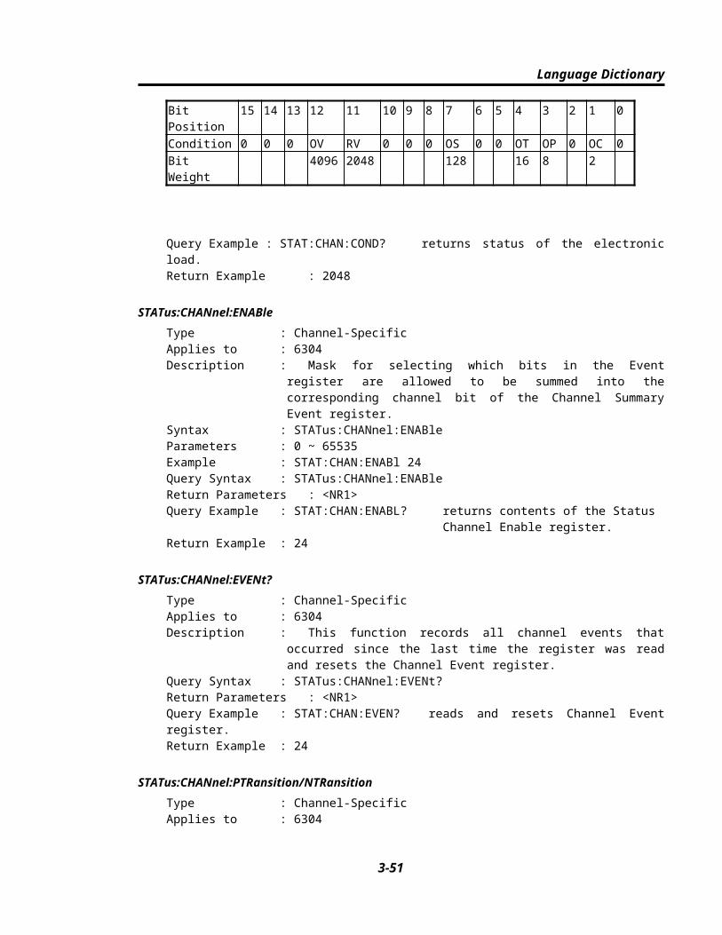
Status Reporting
■ Program the PTR/NTR filter to select which way of a condition transition on a bit in the Questionable Status Condition register will set the corresponding bit in the Event registers.
■ Reading the Questionable Status Event register resets it to zero.
■ The Questionable status Enable register can be programmed to specify which questionable status event bits are logically-ORed to become Bit 5(ESB bit) in the Status Byte register.
Table 4-2. Bit Description of Questionable Status
MnemonicBitValueMeaning
CE/OC12Current Error (Overcurrent).
PE/OP38Power Error (Overpower).
TE/OT416Temperature Error (Overtemperature).
OS7128Timing measurement end.
RV112048Reverse voltage on input.
OV124096Overvoltage.
4.6 Output Queue
4-4

Status Reporting
■ The Output Queue stores output messages until they are read from the electronic load.
■ The Output Queue stores messages sequentially on a FIFO (First-In, First-Out) basis.
■ When there is data in the queue, it sets it 4 (MAV bit) in the Status Byte register.
4.7 Standard Event Status
■ All programming errors that have occurred will set one or more of the error bits in the Standard Event Status register. Table 4-3 describes the standard events that apply to the Chroma 6300 electronic load.
■ Reading the Standard Event Status register resets it to zero.
■ The Standard Event Enable register can be programmed to specify which standard event bits are logically-ORed to become Bit 5 (ESB bit) in the Status Byte register.
Table 4-3 Bit Description of Standard Event Status
MnemonicBitValueMeaning
QYE24Query Error. The output queue was read when no data was present or the data in the queue was lost.
DDE38Device Dependent Error. Memory was lost, or self-test failed.
EXE416Execution Error. A command parameter was outside the legal range or inconsistent with the electronic load‘s operation, or the command could not be executed due to some operating condition.
4-5

Status Reporting
CME532Command Error. A syntax or semantic error has occurred or the electronic load received a <GET> within a program message.
4.8 Status Byte register
■ The Status Byte register summarizes all of the status events from all status registers. Table 4-4 describes the status events that apply to the electronic load.
■ The Status Byte register can be read with a serial poll or *STB? query.
■ The RQS bit is the only bit that is automatically cleared after a serial poll.
■ When the Status Byte register is read with a *STB? query, Bit 6 of the Status Byte register will contain the MSS bit. The MSS bit indicates that the load has at least one reason for requesting service. *STB? does not affect the status byte.
■ The Status Byte register is cleared by *CLS command.
Status Byte Bit Description.
Table 4-4 Bit Description of Status Byte
MnemonicBitValueMeaning
CSUM2
4Channel Summary. Indicates if an enabled channel event has occurred. Affected by Channel Condition, Channel Event and Channel Summary Event registers.
QUES38Questionable. Indicates if an enabled questionable event has occurred.
4-6

Status Reporting
MAV416Message Available. Indicates if the Output Queue contains data.
ESB532Event Status Bit. Indicates if an enabled standard event has occurred.
RQS/MSS664Request Service/Master Summary Status. During a serial poll, RQS is returned and cleared. For an *STB? query, MSS is returned without being cleared.
4.9 Service Request Enable register
■ The Service Request Enable register can be programmed to specify which bits in the Status Byte register will generate service requests.
4-7


![Reg Form LH 19 & XH2 [fillable form]](https://img.pdfslide.tips/doc/110x75/568c52f51a28ab4916b8c715/reg-form-lh-19-xh2-fillable-form.jpg)
