Embed Size (px)
Citation preview
J. Aerosp.Technol. Manag., São José dos Campos, Vol.2, No.2, pp. 211-218, May-Aug., 2010 211
José A. Orlowski de Garcia*Instituto de Aeronáutica e Espaço
São José dos Campos – [email protected]
Gérson Luiz de LimaInstituto Nacional de Pesquisas Espaciais
São José dos Campos – [email protected]
Wilson D. Bocallão PereiraInstituto de Aeronáutica e Espaço
São José dos Campos – [email protected]
Valdir Alves GuimarãesUnivers. Estadual Paulista
Guaratinguetá – [email protected]
Carlos de Moura NetoInstituto Tecnológico de Aeronáutica
São José dos Campos – [email protected]
Ronaldo Pinheiro R. ParanhosUniversidade Estadual do Norte Fluminense
Rio de Janeiro – [email protected]
* author for correspondence
Characterization of titanium welded joints by the orbital gas tungsten arc welding process for aerospace applicationAbstract: In this work, three welding programs for orbital gas tungsten arc welding (GTAW), previously developed, were used, using pulsed current and increasing speed (#A), constant current (#B) and pulsed current and decreasing current (#C). One of these should be used for the propulsion system of the Satellite CBERS (China – Brazil Earth Resources Satellite). Welded joints using tubes of commercially pure titanium were obtained with these procedures, which were characterized by means of mechanical and metallographic tests. The obtained results showed that the three welding procedures produce welded joints free of defects and with adequate shape. Although small differences on mechanical properties and on microstructure have been observed, the three welding programs attained compatible results with international standards used in the aerospace segment. The welding program #B, due to the reduced heat input used, was considered to obtain slightly advantage over the others.
Keywords: Orbital GTAW, Titanium, Satellite.
INTRODUCTION
Orbital welding was developed at the beginning of the 1960’s to provide the aerospace industry with the basic conditions to manufacture highly reliable components.
The existence of failures of joints in hydraulic systems joined by fittings that had been exposed to vibrations and mechanical stresses – during flights at speeds close to that of the speed of sound – brought about the need for a more reliable joining technology. In this way, the orbital system was developed from the already existing gas tungsten arc welding (GTAW) process (Henon, 1998; Henon, n.d.; Orbimatic, n.d.).
The orbital GTAW system is used in the industrial welding of tubes and ducts of diverse sized diameters and thicknesses in situations where quality and productivity go hand in hand. The minimal heat input permits distortion control and the retaining of dimensional accuracy (Orbimatic, n.d.; Mannion, 1999; Henon, n.d.; Morgan and Henon, 1999; Brond and Henon, 2000; Littlewood and Henon, 2000).
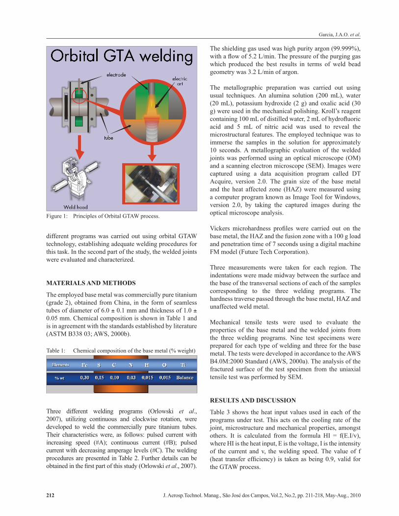
The welding of small diameter tubes with reduced thickness involves square butt joint and single pass. The tubes are maintained in a fixed position, while the electrode moves along the joint, forming a homogeneous weld bead whose properties are close to those of the base metal. The operation is carried out in an inert gas environment which is responsible for shielding the extremities of the electrode, the fusion zone and the heated regions of the component against atmospheric contamination (Mannion, 1999; Morgan and Henon, 1999; Arc Machines, Inc., 2001). Figure 1 shows the principles of orbital GTAW.
The success of orbital GTAW technology applied in the aerospace sector depends not only on the programming of the primary welding parameters, but also on a series of boundary/outlying conditions (chemical composition of the material, setup requirements, type and purity of the gases, type and geometry of the electrode, amongst others) which, together, provide the consistency and quality of the welded components.
This study is part of an important national effort which allows the Brazilian aerospace industry to develop part of the technology to build satellites. In the first part of the study (Orlowski et al., 2007), the development of three
Received: 06/05/10 Accepted: 09/06/10
doi: 10.5028/jatm.2010.02026710
Garcia, J.A.O. et al.
J. Aerosp.Technol. Manag., São José dos Campos, Vol.2, No.2, pp. 211-218, May-Aug., 2010212
different programs was carried out using orbital GTAW technology, establishing adequate welding procedures for this task. In the second part of the study, the welded joints were evaluated and characterized.
MATERIALS AND METHODS
The employed base metal was commercially pure titanium (grade 2), obtained from China, in the form of seamless tubes of diameter of 6.0 ± 0.1 mm and thickness of 1.0 ± 0.05 mm. Chemical composition is shown in Table 1 and is in agreement with the standards established by literature (ASTM B338 03; AWS, 2000b).
The shielding gas used was high purity argon (99.999%), with a flow of 5.2 L/min. The pressure of the purging gas which produced the best results in terms of weld bead geometry was 3.2 L/min of argon.
The metallographic preparation was carried out using usual techniques. An alumina solution (200 mL), water (20 mL), potassium hydroxide (2 g) and oxalic acid (30 g) were used in the mechanical polishing. Kroll’s reagent containing 100 mL of distilled water, 2 mL of hydrofluoric acid and 5 mL of nitric acid was used to reveal the microstructural features. The employed technique was to immerse the samples in the solution for approximately 10 seconds. A metallographic evaluation of the welded joints was performed using an optical microscope (OM) and a scanning electron microscope (SEM). Images were captured using a data acquisition program called DT Acquire, version 2.0. The grain size of the base metal and the heat affected zone (HAZ) were measured using a computer program known as Image Tool for Windows, version 2.0, by taking the captured images during the optical microscope analysis.
Vickers microhardness profiles were carried out on the base metal, the HAZ and the fusion zone with a 100 g load and penetration time of 7 seconds using a digital machine FM model (Future Tech Corporation).
Three measurements were taken for each region. The indentations were made midway between the surface and the base of the transversal sections of each of the samples corresponding to the three welding programs. The hardness traverse passed through the base metal, HAZ and unaffected weld metal.
Mechanical tensile tests were used to evaluate the properties of the base metal and the welded joints from the three welding programs. Nine test specimens were prepared for each type of welding and three for the base metal. The tests were developed in accordance to the AWS B4.0M:2000 Standard (AWS, 2000a). The analysis of the fractured surface of the test specimen from the uniaxial tensile test was performed by SEM.
RESULTS AND DISCUSSION
Table 3 shows the heat input values used in each of the programs under test. This acts on the cooling rate of the joint, microstructure and mechanical properties, amongst others. It is calculated from the formula HI = f(E.I/v), where HI is the heat input, E is the voltage, I is the intensity of the current and v, the welding speed. The value of f (heat transfer efficiency) is taken as being 0.9, valid for the GTAW process.
Figure 1: Principles of Orbital GTAW process.
Table 1: Chemical composition of the base metal (% weight)
Three different welding programs (Orlowski et al., 2007), utilizing continuous and clockwise rotation, were developed to weld the commercially pure titanium tubes. Their characteristics were, as follows: pulsed current with increasing speed (#A); continuous current (#B); pulsed current with decreasing amperage levels (#C). The welding procedures are presented in Table 2. Further details can be obtained in the first part of this study (Orlowski et al., 2007).
Characterization of titanium welded joints by the orbital gas tungsten arc welding process for aerospace application
J. Aerosp.Technol. Manag., São José dos Campos, Vol.2, No.2, pp. 211-218, May-Aug., 2010 213
as iron, present in the form of impurities in commercially pure titanium, stabilizes β phase elevating by up to 5% – in quantitative terms – its presence in the matrix.
Specifically in the case of titanium, the fusion zone is characterized by temperatures above the solidus line of the material. In the HAZ, the temperature levels reach values above that of the allotropic transformation, β
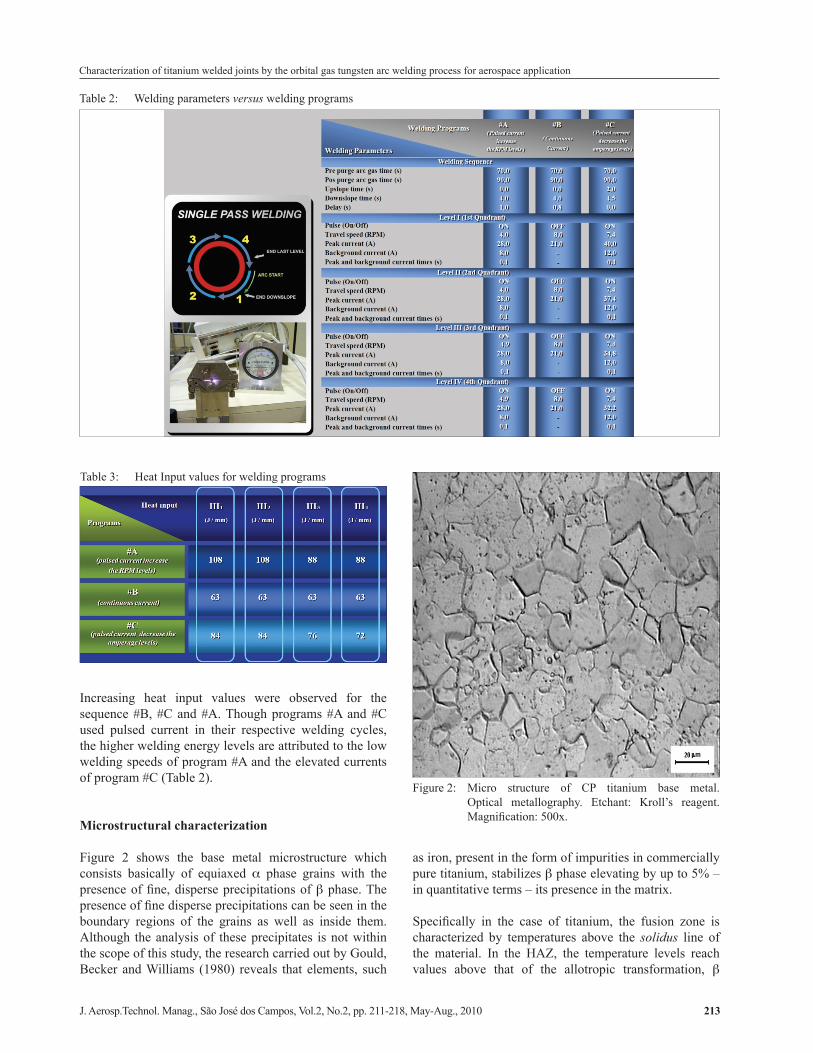
Table 2: Welding parameters versus welding programs
Table 3: Heat Input values for welding programs
Increasing heat input values were observed for the sequence #B, #C and #A. Though programs #A and #C used pulsed current in their respective welding cycles, the higher welding energy levels are attributed to the low welding speeds of program #A and the elevated currents of program #C (Table 2).
Microstructural characterization
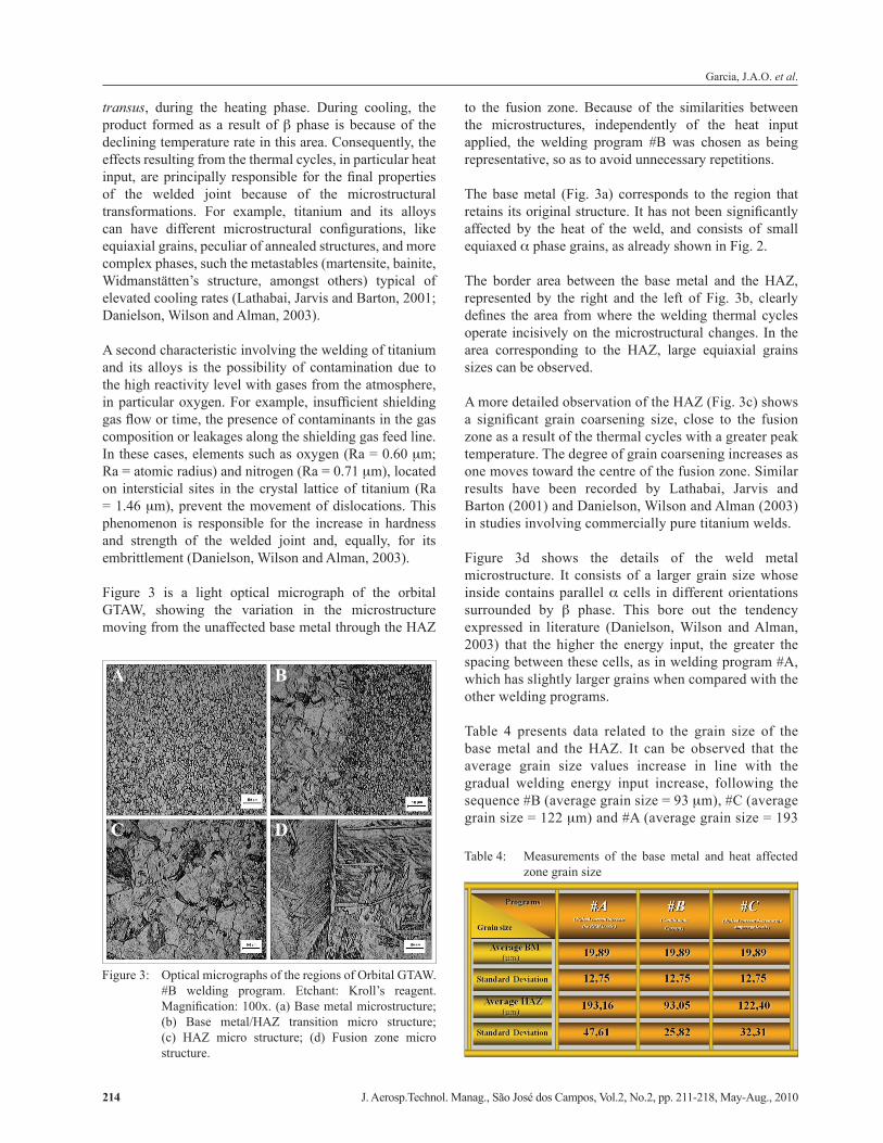
Figure 2 shows the base metal microstructure which consists basically of equiaxed α phase grains with the presence of fine, disperse precipitations of β phase. The presence of fine disperse precipitations can be seen in the boundary regions of the grains as well as inside them. Although the analysis of these precipitates is not within the scope of this study, the research carried out by Gould, Becker and Williams (1980) reveals that elements, such
Figure 2: Micro structure of CP titanium base metal. Optical metallography. Etchant: Kroll’s reagent. Magnification: 500x.
Garcia, J.A.O. et al.
J. Aerosp.Technol. Manag., São José dos Campos, Vol.2, No.2, pp. 211-218, May-Aug., 2010214
transus, during the heating phase. During cooling, the product formed as a result of β phase is because of the declining temperature rate in this area. Consequently, the effects resulting from the thermal cycles, in particular heat input, are principally responsible for the final properties of the welded joint because of the microstructural transformations. For example, titanium and its alloys can have different microstructural configurations, like equiaxial grains, peculiar of annealed structures, and more complex phases, such the metastables (martensite, bainite, Widmanstätten’s structure, amongst others) typical of elevated cooling rates (Lathabai, Jarvis and Barton, 2001; Danielson, Wilson and Alman, 2003).
A second characteristic involving the welding of titanium and its alloys is the possibility of contamination due to the high reactivity level with gases from the atmosphere, in particular oxygen. For example, insufficient shielding gas flow or time, the presence of contaminants in the gas composition or leakages along the shielding gas feed line. In these cases, elements such as oxygen (Ra = 0.60 μm; Ra = atomic radius) and nitrogen (Ra = 0.71 μm), located on intersticial sites in the crystal lattice of titanium (Ra = 1.46 μm), prevent the movement of dislocations. This phenomenon is responsible for the increase in hardness and strength of the welded joint and, equally, for its embrittlement (Danielson, Wilson and Alman, 2003).
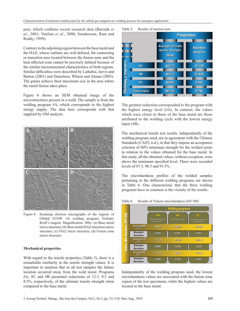
Figure 3 is a light optical micrograph of the orbital GTAW, showing the variation in the microstructure moving from the unaffected base metal through the HAZ
to the fusion zone. Because of the similarities between the microstructures, independently of the heat input applied, the welding program #B was chosen as being representative, so as to avoid unnecessary repetitions.
The base metal (Fig. 3a) corresponds to the region that retains its original structure. It has not been significantly affected by the heat of the weld, and consists of small equiaxed α phase grains, as already shown in Fig. 2.
The border area between the base metal and the HAZ, represented by the right and the left of Fig. 3b, clearly defines the area from where the welding thermal cycles operate incisively on the microstructural changes. In the area corresponding to the HAZ, large equiaxial grains sizes can be observed.
A more detailed observation of the HAZ (Fig. 3c) shows a significant grain coarsening size, close to the fusion zone as a result of the thermal cycles with a greater peak temperature. The degree of grain coarsening increases as one moves toward the centre of the fusion zone. Similar results have been recorded by Lathabai, Jarvis and Barton (2001) and Danielson, Wilson and Alman (2003) in studies involving commercially pure titanium welds.
Figure 3d shows the details of the weld metal microstructure. It consists of a larger grain size whose inside contains parallel α cells in different orientations surrounded by β phase. This bore out the tendency expressed in literature (Danielson, Wilson and Alman, 2003) that the higher the energy input, the greater the spacing between these cells, as in welding program #A, which has slightly larger grains when compared with the other welding programs.
Table 4 presents data related to the grain size of the base metal and the HAZ. It can be observed that the average grain size values increase in line with the gradual welding energy input increase, following the sequence #B (average grain size = 93 μm), #C (average grain size = 122 μm) and #A (average grain size = 193
Table 4: Measurements of the base metal and heat affected zone grain size
A B
C D
Figure 3: Optical micrographs of the regions of Orbital GTAW. #B welding program. Etchant: Kroll’s reagent. Magnification: 100x. (a) Base metal microstructure; (b) Base metal/HAZ transition micro structure; (c) HAZ micro structure; (d) Fusion zone micro structure.
Characterization of titanium welded joints by the orbital gas tungsten arc welding process for aerospace application
J. Aerosp.Technol. Manag., São José dos Campos, Vol.2, No.2, pp. 211-218, May-Aug., 2010 215
μm), which confirms recent research data (Barreda et al., 2001; Yunlian et al., 2000; Sundaresan, Ram and Reddy, 1999).
Contrary to the adjoining region between the base metal and the HAZ, whose outlines are well defined, the connecting or transition area located between the fusion zone and the heat affected zone cannot be precisely defined because of the similar microstructural characteristics of both regions. Similar difficulties were described by Lathabai, Jarvis and Barton (2001) and Danielson, Wilson and Alman (2003). The grains achieve their maximum size in the area where the metal fusion takes place.
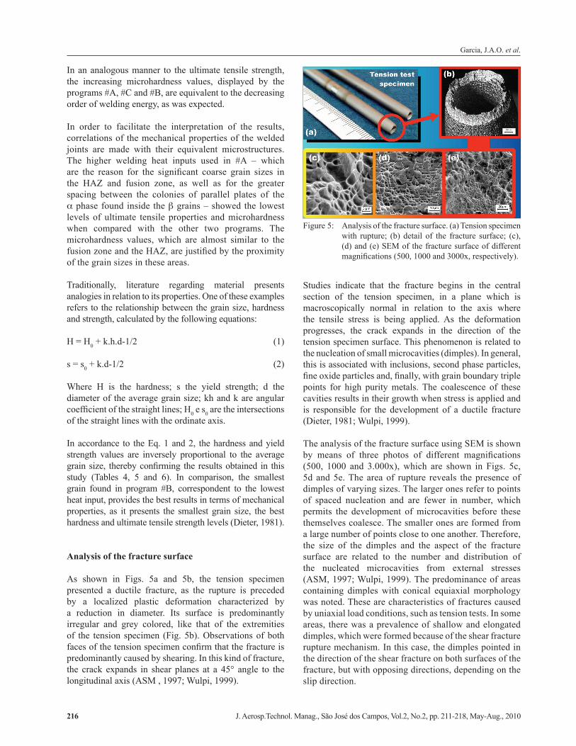
Figure 4 shows an SEM obtained image of the microstructures present in a weld. The sample is from the welding program #A, which corresponds to the highest energy supply. The data here corresponds with that supplied by OM analysis.
The greatest reduction corresponded to the program with the highest energy level (#A). In contrast, the values which were closer to those of the base metal are those attributed to the welding cycle with the lowest energy input (#B).
The mechanical tensile test results, independently of the welding program used, are in agreement with the Chinese Standards (CAST, n.d.), in that they impose an acceptance criterion of 80% minimum strength for the welded joints in relation to the values obtained for the base metal. In this study, all the obtained values, without exception, were above the minimum specified level. There were recorded levels of 87.5, 90.5 and 91.5%.
The microhardness profiles of the welded samples pertaining to the different welding programs are shown in Table 6. One characteristic that the three welding programs have in common is the vicinity of the results.
A B
C D
Figure 4: Scanning electron micrographs of the regions of Orbital GTAW. #A welding program. Etchant: Kroll’s reagent. Magnification: 500x. (a) Base metal micro structure; (b) Base metal/HAZ transition micro structure; (c) HAZ micro structure; (d) Fusion zone micro structure.
Table 5: Results of tension tests
Mechanical properties
With regard to the tensile properties (Table 5), there is a remarkable similarity in the tensile strength values. It is important to mention that in all test samples the failure location occurred away from the weld metal. Programs #A, #C and #B presented reductions of 12.5, 9.5 and 8.5%, respectively, of the ultimate tensile strength when compared to the base metal.
Table 6: Results of Vickers microhardness (HV100)
Independently of the welding program used, the lowest microhardness values are associated with the fusion zone region of the test specimens, while the highest values are located in the base metal.
Garcia, J.A.O. et al.
J. Aerosp.Technol. Manag., São José dos Campos, Vol.2, No.2, pp. 211-218, May-Aug., 2010216
In an analogous manner to the ultimate tensile strength, the increasing microhardness values, displayed by the programs #A, #C and #B, are equivalent to the decreasing order of welding energy, as was expected.
In order to facilitate the interpretation of the results, correlations of the mechanical properties of the welded joints are made with their equivalent microstructures. The higher welding heat inputs used in #A – which are the reason for the significant coarse grain sizes in the HAZ and fusion zone, as well as for the greater spacing between the colonies of parallel plates of the α phase found inside the β grains – showed the lowest levels of ultimate tensile properties and microhardness when compared with the other two programs. The microhardness values, which are almost similar to the fusion zone and the HAZ, are justified by the proximity of the grain sizes in these areas.
Traditionally, literature regarding material presents analogies in relation to its properties. One of these examples refers to the relationship between the grain size, hardness and strength, calculated by the following equations:
H = H0 + k.h.d-1/2 (1)
s = s0 + k.d-1/2 (2)
Where H is the hardness; s the yield strength; d the diameter of the average grain size; kh and k are angular coefficient of the straight lines; H0 e s0 are the intersections of the straight lines with the ordinate axis.
In accordance to the Eq. 1 and 2, the hardness and yield strength values are inversely proportional to the average grain size, thereby confirming the results obtained in this study (Tables 4, 5 and 6). In comparison, the smallest grain found in program #B, correspondent to the lowest heat input, provides the best results in terms of mechanical properties, as it presents the smallest grain size, the best hardness and ultimate tensile strength levels (Dieter, 1981).
Analysis of the fracture surface
As shown in Figs. 5a and 5b, the tension specimen presented a ductile fracture, as the rupture is preceded by a localized plastic deformation characterized by a reduction in diameter. Its surface is predominantly irregular and grey colored, like that of the extremities of the tension specimen (Fig. 5b). Observations of both faces of the tension specimen confirm that the fracture is predominantly caused by shearing. In this kind of fracture, the crack expands in shear planes at a 45° angle to the longitudinal axis (ASM , 1997; Wulpi, 1999).
Studies indicate that the fracture begins in the central section of the tension specimen, in a plane which is macroscopically normal in relation to the axis where the tensile stress is being applied. As the deformation progresses, the crack expands in the direction of the tension specimen surface. This phenomenon is related to the nucleation of small microcavities (dimples). In general, this is associated with inclusions, second phase particles, fine oxide particles and, finally, with grain boundary triple points for high purity metals. The coalescence of these cavities results in their growth when stress is applied and is responsible for the development of a ductile fracture (Dieter, 1981; Wulpi, 1999).
The analysis of the fracture surface using SEM is shown by means of three photos of different magnifications (500, 1000 and 3.000x), which are shown in Figs. 5c, 5d and 5e. The area of rupture reveals the presence of dimples of varying sizes. The larger ones refer to points of spaced nucleation and are fewer in number, which permits the development of microcavities before these themselves coalesce. The smaller ones are formed from a large number of points close to one another. Therefore, the size of the dimples and the aspect of the fracture surface are related to the number and distribution of the nucleated microcavities from external stresses (ASM, 1997; Wulpi, 1999). The predominance of areas containing dimples with conical equiaxial morphology was noted. These are characteristics of fractures caused by uniaxial load conditions, such as tension tests. In some areas, there was a prevalence of shallow and elongated dimples, which were formed because of the shear fracture rupture mechanism. In this case, the dimples pointed in the direction of the shear fracture on both surfaces of the fracture, but with opposing directions, depending on the slip direction.
Figure 5: Analysis of the fracture surface. (a) Tension specimen with rupture; (b) detail of the fracture surface; (c), (d) and (e) SEM of the fracture surface of different magnifications (500, 1000 and 3000x, respectively).
Characterization of titanium welded joints by the orbital gas tungsten arc welding process for aerospace application
J. Aerosp.Technol. Manag., São José dos Campos, Vol.2, No.2, pp. 211-218, May-Aug., 2010 217
On the contrary, where there were tear fractures, the dimples indicated a one-way fracture, determined by the coalescing mechanisms of the microcavities (Dieter, 1981; ASM, 1997; Wulpi, 1999).
In short, the fracture is located in a part of the test specimen about 31 mm away from the center of the weld bead. The temperature levels reached here are not sufficient for eventual microstructure transformations. There was no evidence of cracks, pores or inclusions.
CONCLUSIONS
Programs #A, #B e #C, developed for Orbital GTAW of titanium tubes, proved to be adequate and displayed satisfactory mechanical results for the welded joint.
Program #A (pulsed current and increasing speed) produced a weld bead with a lower hardness and ultimate tensile values, which was attributed to the greater grain size and spacing between the colonies of parallel plates of α phase. Both of these are characterized by a low cooling rate.
Program #B (continuous current), correspondent to a lower heat input value, provided the best result between the hardness and mechanical properties due to the smaller grain size.
REFERENCES
American Society for Metals (ASM), 1997, “Fractography”, 9th ed, ASM, Ohio, USA.
American Welding Society (AWS), 2000a, “AWS B4.0M:2000. Standard methods for mechanical testing of welds”, AWS, Miami, FL, USA.
American Welding Society (AWS), 2000b, “AWS D10.6/ D10.6M:2000. Recommended practices for gas tungsten arc welding of titanium pipping and tubing”, AWS, Miami, FL, USA.
Arc Machines, Inc., 2001, “Orbital welding delivers treatment plant on time”. Welding Journal, Mar., pp. 51-52.
Barreda, J.L., et al., 2001, “Electron bean welded high thickness Ti6Al4V plates using filler metal of similar and different composition to the basic plate”. Vacuum, Vol. 62, No 2-3, pp.143-150. doi: 10.1016/S0042-207X(00)00454-1.
Brond, A., Henon, B.K, 2000, “Orbital welding technology for pharmaceutical piping systems”. Latin
American Phamaceutical Show, Centro Costa Salguero, Buenos Aires, Argentina, Available at: <http://www.arcmachines.com/appPages/atw02.html>. Access on Oct 24, 2001.
Chinese Academy of Space Technology (CAST), n.d., “Chinese Standard CBERS propulsion subsystem pipe integrating and welding requirement (specification)”.
Chinese Academy of Space Technology (CAST), n.d., “Chinese Standard CBERS propulsion subsystem pipe leakage check requirement (specification)”.
Danielson, P., Wilson, R., Alman, D, 2003, “Microstructure of titanium welds”, Advanced Material & Processes, Vol. 161, No 2, pp. 39-42.
Dieter, G.E., 1981, “Metalurgia mecânica”, 2nd ed, Ed. Guanabara Koogan, Rio de Janeiro, Brazil, 653p.
Gould, J.E., Becker, D., Williams, J.C., 1980, “Microstructural characterization of titanium weldments”, In: Kossowski, R., Glicksman, M.E. (Eds.), “Physical Metallurgy of Metal Joinning”, The Metallurgical Society of AIME, Warrendale, PA, USA, pp. 199-221.
Henon, B.K., n.d., “Matsushita completes ultra high purity nitrogen system reducing contaminants to PPB levels”. Available at: <http://www.arcmachines.com/appPages/masca02.html>. Access on Oct 22, 2001.
Henon, B.K., n.d., “Practical application of orbital tube and pipe welding”, Reprinted of Practical Welding Today. Available at: <http://www.arcmachines.com/appPages/pract02.html>. Access on Nov 17, 2001.
Henon, B.K., 1998, “Orbital welding of small diameter tubing”, Reprinted of Tube International, 03/1998, Available at: <http://www.arcmachines.com/appPages/smalldia02.html>. Access on Oct 24, 2001.
Lathabai, S., Jarvis, B.L., Barton, K.J., 2001, “Comparison of keyhole and conventional gas tungsten arc welds in commercially pure titanium”, Materials Science and Engineering A, Vol. 299, No 1-2, pp. 81-93. doi: 10.1016/S0921-5093(00)01408-8.
Littlewood, G., Henon, B.K., 2000, “A case study of the installation of an orbitally welded higienic piping system”. Reprinted of Pharmaceutical Technology Europe, 03/2000. Available at: <http://www.arcmachines.com/appPages/pharmeo02.html>. Access on Oct 10, 2001.
Mannion, B., 1999, “The fundamentals of orbital welding”, Welding Design and Fabrication, Feb., pp. 22-26.
Garcia, J.A.O. et al.
J. Aerosp.Technol. Manag., São José dos Campos, Vol.2, No.2, pp. 211-218, May-Aug., 2010218
Morgan, J., Henon, B.K., 1999, “Discovering applications for orbital fusion welding”. Reprinted of The Tube & Pipe Journal, 03/1999. Available at: <http://www.arcmachines.com/appPages/tpj02.html>. Access on Oct 24, 2001.
Orbimatic, n.d., “Origins and development of orbital welding”, Available at: <http://www.subcontractingtalk.com/news/orb/orb131.html>, Access on Apr 11, 2003.
Orlowski J.A.G, et al., 2007, “Development of the Welding Technology of Titanium by the Orbital TIG Process for the Brazilian Airspace Segment. Part 1: Experimental Setup”. Soldagem & Inspeção, Vol. 12, No 1, pp.46-54.
Sundaresan, S., Ram, G.D.J., Reddy, G.M., 1999, “Microstructural refinement of weld fusion zones in α–β titanium alloys using pulsed current welding”. Materials
Science & Engineering A, Vol. 262, No 1-2, pp. 88-100. doi: 10.1016/S0921-5093(98)01010-7.
Wulpi, D.J., 1999, “Understanding how components fail”. 2nd ed. ASM International, Ohio, USA, 262p.
Yung, W.K.C, et al., 1997, “An investigation into welding parameters affecting the tensile properties of titanium welds”. Journal of Materials Processing Technology, Vol. 63, No 1-3, pp. 759-764. doi: 10.1016/S0924-0136(96)02719-7.
Yunlian, Q., et al., 2000, “Electron beam welding, laser beam welding and gas tungsten arc welding of titanium sheet”. Materials Science & Engineering A, Vol. 280, No 1, pp. 177-181. doi: 10.1016/S0921-5093(99)00662-0.