Embed Size (px)
DESCRIPTION
Chequered Plate design
Citation preview
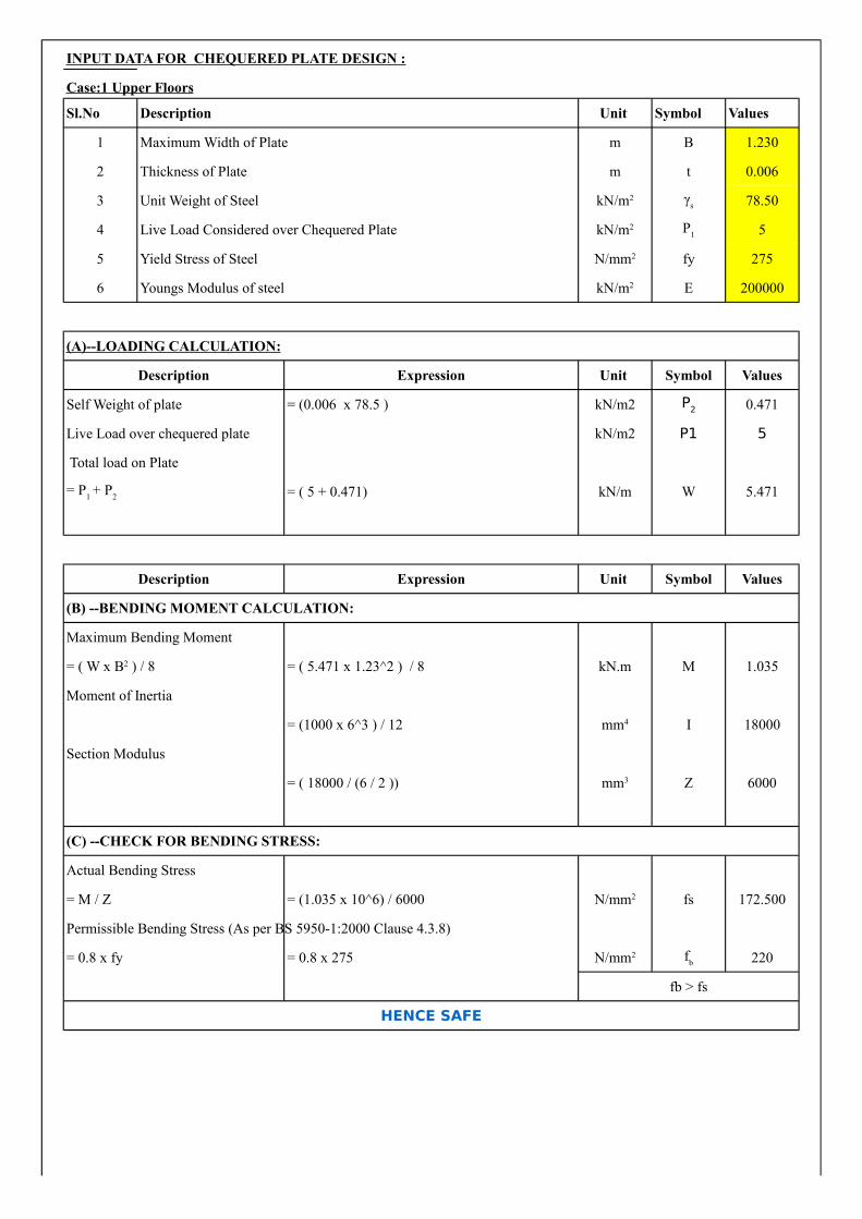
INPUT DATA FOR CHEQUERED PLATE DESIGN :
Case:1 Upper Floors
Sl.No Description Unit Symbol Values
1 Maximum Width of Plate m B 1.230
2 Thickness of Plate m t 0.006
3 Unit Weight of Steel 78.50
4 Live Load Considered over Chequered Plate 5
5 Yield Stress of Steel fy 275
6 Youngs Modulus of steel E 200000
(A)--LOADING CALCULATION:
Description Expression Unit Symbol Values
Self Weight of plate = (0.006 x 78.5 ) kN/m2 0.471
Live Load over chequered plate kN/m2 P1 5
Total load on Plate
= ( 5 + 0.471) kN/m W 5.471
Description Expression Unit Symbol Values
(B) --BENDING MOMENT CALCULATION:
Maximum Bending Moment
= ( 5.471 x 1.23^2 ) / 8 kN.m M 1.035
Moment of Inertia
= (1000 x 6^3 ) / 12 I 18000
Section Modulus
= ( 18000 / (6 / 2 )) Z 6000
(C) --CHECK FOR BENDING STRESS:
Actual Bending Stress
= M / Z = (1.035 x 10^6) / 6000 fs 172.500
Permissible Bending Stress (As per BS 5950-1:2000 Clause 4.3.8)
= 0.8 x fy = 0.8 x 275 220
fb > fs
HENCE SAFE
kN/m2 γs
kN/m2 P1
N/mm2
kN/m2
P2
= P1 + P
2
= ( W x B2 ) / 8
mm4
mm3
N/mm2
N/mm2 fb
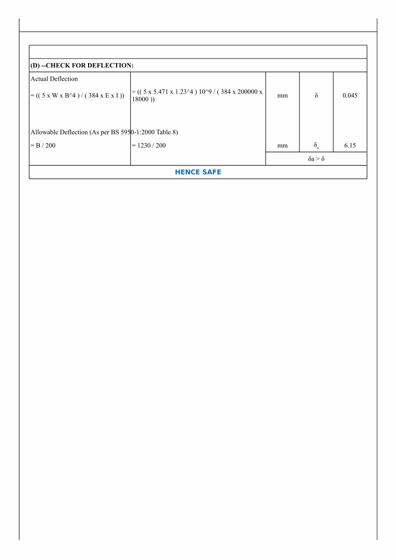
(D) --CHECK FOR DEFLECTION:
Actual Deflection
= (( 5 x W x B^4 ) / ( 384 x E x I )) mm δ 0.045
Allowable Deflection (As per BS 5950-1:2000 Table 8)
= B / 200 = 1230 / 200 mm 6.15
δa > δ
HENCE SAFE
= (( 5 x 5.471 x 1.23^4 ) 10^9 / ( 384 x 200000 x 18000 ))
δa

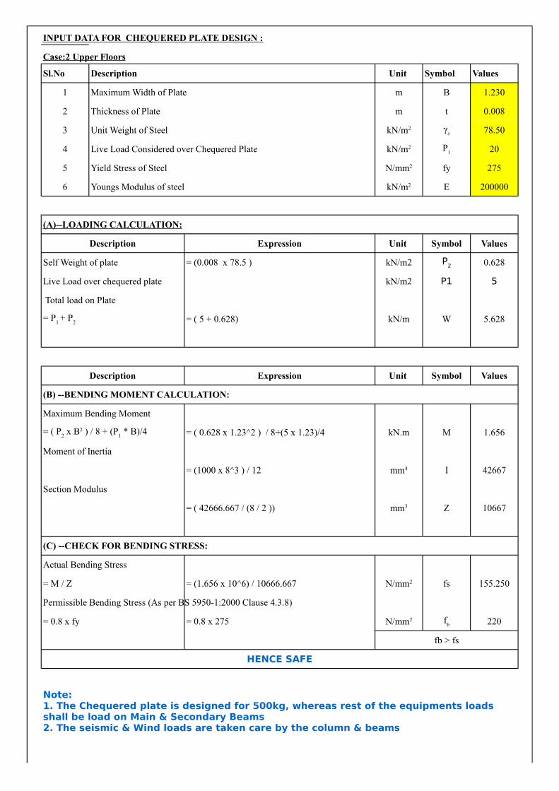
INPUT DATA FOR CHEQUERED PLATE DESIGN :
Case:2 Upper Floors
Sl.No Description Unit Symbol Values
1 Maximum Width of Plate m B 1.230
2 Thickness of Plate m t 0.008
3 Unit Weight of Steel 78.50
4 Live Load Considered over Chequered Plate 20
5 Yield Stress of Steel fy 275
6 Youngs Modulus of steel E 200000
(A)--LOADING CALCULATION:
Description Expression Unit Symbol Values
Self Weight of plate = (0.008 x 78.5 ) kN/m2 0.628
Live Load over chequered plate kN/m2 P1 5
Total load on Plate
= ( 5 + 0.628) kN/m W 5.628
Description Expression Unit Symbol Values
(B) --BENDING MOMENT CALCULATION:
Maximum Bending Moment
= ( 0.628 x 1.23^2 ) / 8+(5 x 1.23)/4 kN.m M 1.656
Moment of Inertia
= (1000 x 8^3 ) / 12 I 42667
Section Modulus
= ( 42666.667 / (8 / 2 )) Z 10667
(C) --CHECK FOR BENDING STRESS:
Actual Bending Stress
= M / Z = (1.656 x 10^6) / 10666.667 fs 155.250
Permissible Bending Stress (As per BS 5950-1:2000 Clause 4.3.8)
= 0.8 x fy = 0.8 x 275 220
fb > fs
HENCE SAFE
kN/m2 γs
kN/m2 P1
N/mm2
kN/m2
P2
= P1 + P
2
= ( P2 x B2 ) / 8 + (P
1 * B)/4
mm4
mm3
N/mm2
N/mm2 fb
Note: 1. The Chequered plate is designed for 500kg, whereas rest of the equipments loads shall be load on Main & Secondary Beams2. The seismic & Wind loads are taken care by the column & beams
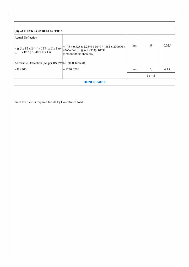
(D) --CHECK FOR DEFLECTION:
Actual Deflection
mm δ 0.025
Allowable Deflection (As per BS 5950-1:2000 Table 8)
= B / 200 = 1230 / 200 mm 6.15
δa > δ
HENCE SAFE
8mm thk plate is required for 500kg Concetrated load
= (( 5 x P2 x B^4 ) / ( 384 x E x I ))+ (( P1 x B^3 ) / ( 48 x E x I ))
= (( 5 x 0.628 x 1.23^4 ) 10^9 / ( 384 x 200000 x 42666.667 ))+((5x1.23^3)x10^9/(48x200000x42666.667)
δa

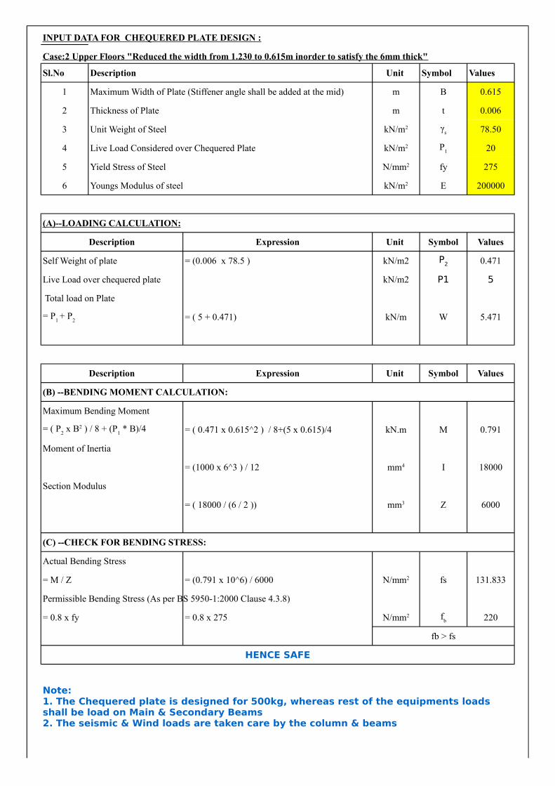
INPUT DATA FOR CHEQUERED PLATE DESIGN :
Case:2 Upper Floors "Reduced the width from 1.230 to 0.615m inorder to satisfy the 6mm thick"
Sl.No Description Unit Symbol Values
1 Maximum Width of Plate (Stiffener angle shall be added at the mid) m B 0.615
2 Thickness of Plate m t 0.006
3 Unit Weight of Steel 78.50
4 Live Load Considered over Chequered Plate 20
5 Yield Stress of Steel fy 275
6 Youngs Modulus of steel E 200000
(A)--LOADING CALCULATION:
Description Expression Unit Symbol Values
Self Weight of plate = (0.006 x 78.5 ) kN/m2 0.471
Live Load over chequered plate kN/m2 P1 5
Total load on Plate
= ( 5 + 0.471) kN/m W 5.471
Description Expression Unit Symbol Values
(B) --BENDING MOMENT CALCULATION:
Maximum Bending Moment
= ( 0.471 x 0.615^2 ) / 8+(5 x 0.615)/4 kN.m M 0.791
Moment of Inertia
= (1000 x 6^3 ) / 12 I 18000
Section Modulus
= ( 18000 / (6 / 2 )) Z 6000
(C) --CHECK FOR BENDING STRESS:
Actual Bending Stress
= M / Z = (0.791 x 10^6) / 6000 fs 131.833
Permissible Bending Stress (As per BS 5950-1:2000 Clause 4.3.8)
= 0.8 x fy = 0.8 x 275 220
fb > fs
HENCE SAFE
kN/m2 γs
kN/m2 P1
N/mm2
kN/m2
P2
= P1 + P
2
= ( P2 x B2 ) / 8 + (P
1 * B)/4
mm4
mm3
N/mm2
N/mm2 fb
Note: 1. The Chequered plate is designed for 500kg, whereas rest of the equipments loads shall be load on Main & Secondary Beams2. The seismic & Wind loads are taken care by the column & beams
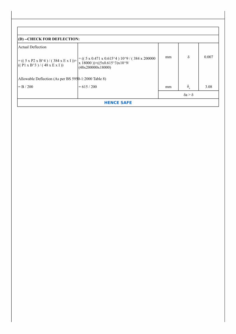
(D) --CHECK FOR DEFLECTION:
Actual Deflection
mm δ 0.007
Allowable Deflection (As per BS 5950-1:2000 Table 8)
= B / 200 = 615 / 200 mm 3.08
δa > δ
HENCE SAFE
= (( 5 x P2 x B^4 ) / ( 384 x E x I ))+ (( P1 x B^3 ) / ( 48 x E x I ))
= (( 5 x 0.471 x 0.615^4 ) 10^9 / ( 384 x 200000 x 18000 ))+((5x0.615^3)x10^9/(48x200000x18000)
δa

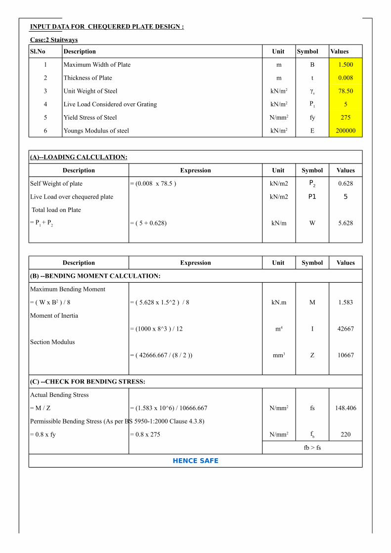
INPUT DATA FOR CHEQUERED PLATE DESIGN :
Case:2 Staitways
Sl.No Description Unit Symbol Values
1 Maximum Width of Plate m B 1.500
2 Thickness of Plate m t 0.008
3 Unit Weight of Steel 78.50
4 Live Load Considered over Grating 5
5 Yield Stress of Steel fy 275
6 Youngs Modulus of steel E 200000
(A)--LOADING CALCULATION:
Description Expression Unit Symbol Values
Self Weight of plate = (0.008 x 78.5 ) kN/m2 0.628
Live Load over chequered plate kN/m2 P1 5
Total load on Plate
= ( 5 + 0.628) kN/m W 5.628
Description Expression Unit Symbol Values
(B) --BENDING MOMENT CALCULATION:
Maximum Bending Moment
= ( 5.628 x 1.5^2 ) / 8 kN.m M 1.583
Moment of Inertia
= (1000 x 8^3 ) / 12 I 42667
Section Modulus
= ( 42666.667 / (8 / 2 )) Z 10667
(C) --CHECK FOR BENDING STRESS:
Actual Bending Stress
= M / Z = (1.583 x 10^6) / 10666.667 fs 148.406
Permissible Bending Stress (As per BS 5950-1:2000 Clause 4.3.8)
= 0.8 x fy = 0.8 x 275 220
fb > fs
HENCE SAFE
kN/m2 γs
kN/m2 P1
N/mm2
kN/m2
P2
= P1 + P
2
= ( W x B2 ) / 8
m4
mm3
N/mm2
N/mm2 fb
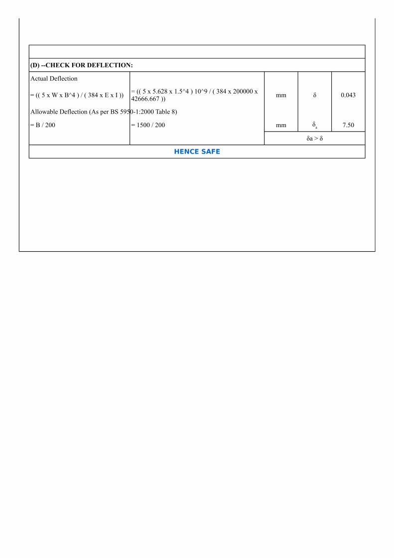
(D) --CHECK FOR DEFLECTION:
Actual Deflection
= (( 5 x W x B^4 ) / ( 384 x E x I )) mm δ 0.043
Allowable Deflection (As per BS 5950-1:2000 Table 8)
= B / 200 = 1500 / 200 mm 7.50
δa > δ
HENCE SAFE
= (( 5 x 5.628 x 1.5^4 ) 10^9 / ( 384 x 200000 x 42666.667 ))
δa
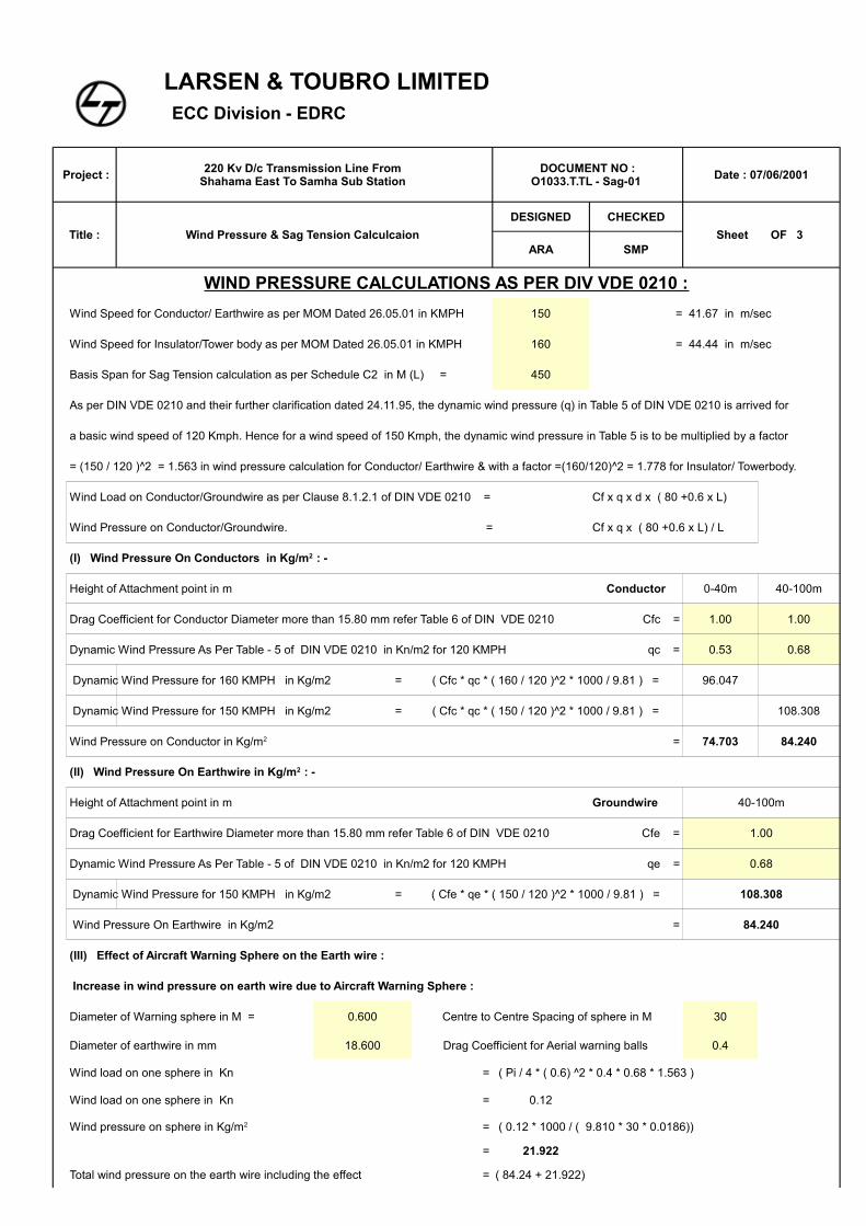
LARSEN & TOUBRO LIMITED ECC Division - EDRC
Project : Date : 07/06/2001
Title : Wind Pressure & Sag Tension Calculcaion
DESIGNED CHECKED
Sheet OF 3 ARA SMP
WIND PRESSURE CALCULATIONS AS PER DIV VDE 0210 :
Wind Speed for Conductor/ Earthwire as per MOM Dated 26.05.01 in KMPH 150 = 41.67 in m/sec
Wind Speed for Insulator/Tower body as per MOM Dated 26.05.01 in KMPH 160 = 44.44 in m/sec
Basis Span for Sag Tension calculation as per Schedule C2 in M (L) = 450
As per DIN VDE 0210 and their further clarification dated 24.11.95, the dynamic wind pressure (q) in Table 5 of DIN VDE 0210 is arrived for
a basic wind speed of 120 Kmph. Hence for a wind speed of 150 Kmph, the dynamic wind pressure in Table 5 is to be multiplied by a factor
= (150 / 120 )^2 = 1.563 in wind pressure calculation for Conductor/ Earthwire & with a factor =(160/120)^2 = 1.778 for Insulator/ Towerbody.
Wind Load on Conductor/Groundwire as per Clause 8.1.2.1 of DIN VDE 0210 = Cf x q x d x ( 80 +0.6 x L)
Wind Pressure on Conductor/Groundwire. = Cf x q x ( 80 +0.6 x L) / L
Height of Attachment point in m Conductor 0-40m 40-100m
Drag Coefficient for Conductor Diameter more than 15.80 mm refer Table 6 of DIN VDE 0210 Cfc = 1.00 1.00
Dynamic Wind Pressure As Per Table - 5 of DIN VDE 0210 in Kn/m2 for 120 KMPH qc = 0.53 0.68
Dynamic Wind Pressure for 160 KMPH in Kg/m2 = ( Cfc * qc * ( 160 / 120 )^2 * 1000 / 9.81 ) = 96.047
Dynamic Wind Pressure for 150 KMPH in Kg/m2 = ( Cfc * qc * ( 150 / 120 )^2 * 1000 / 9.81 ) = 108.308
= 74.703 84.240
Height of Attachment point in m Groundwire 40-100m
Drag Coefficient for Earthwire Diameter more than 15.80 mm refer Table 6 of DIN VDE 0210 Cfe = 1.00
Dynamic Wind Pressure As Per Table - 5 of DIN VDE 0210 in Kn/m2 for 120 KMPH qe = 0.68
Dynamic Wind Pressure for 150 KMPH in Kg/m2 = ( Cfe * qe * ( 150 / 120 )^2 * 1000 / 9.81 ) = 108.308
Wind Pressure On Earthwire in Kg/m2 = 84.240
(III) Effect of Aircraft Warning Sphere on the Earth wire :
Increase in wind pressure on earth wire due to Aircraft Warning Sphere :
Diameter of Warning sphere in M = 0.600 Centre to Centre Spacing of sphere in M 30
Diameter of earthwire in mm 18.600 Drag Coefficient for Aerial warning balls 0.4
Wind load on one sphere in Kn = ( Pi / 4 * ( 0.6) ^2 * 0.4 * 0.68 * 1.563 )
Wind load on one sphere in Kn = 0.12
= ( 0.12 * 1000 / ( 9.810 * 30 * 0.0186))
= 21.922
Total wind pressure on the earth wire including the effect = ( 84.24 + 21.922)
220 Kv D/c Transmission Line From Shahama East To Samha Sub Station
DOCUMENT NO : O1033.T.TL - Sag-01
(I) Wind Pressure On Conductors in Kg/m2 : -
Wind Pressure on Conductor in Kg/m2
(II) Wind Pressure On Earthwire in Kg/m2 : -
Wind pressure on sphere in Kg/m2
LARSEN & TOUBRO LIMITED ECC Division - EDRC
Project : Date : 07/06/2001
Title : Wind Pressure & Sag Tension Calculcaion
DESIGNED CHECKED
Sheet OF 3 ARA SMP
220 Kv D/c Transmission Line From Shahama East To Samha Sub Station
DOCUMENT NO : O1033.T.TL - Sag-01
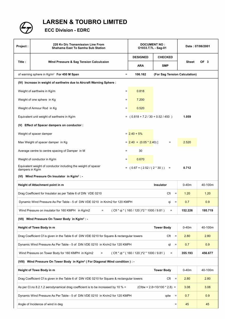
= 106.162 (For Sag Tension Calculation)
(IV) Increase in weight of earthwire due to Aircraft Warning Sphere :
Weight of earthwire in Kg/m = 0.818
Weight of one sphere in Kg = 7.200
Weight of Armour Rod in Kg = 0.520
Equivalent unit weight of earthwire in Kg/m = ( 0.818 + 7.2 / 30 + 0.52 / 450 ) 1.059
(V) Effect of Spacer dampers on conductor :
Weight of spacer damper = 2.40 + 5%
Max Weight of spacer damper in Kg = 2.40 + (0.05 * 2.40) ] = 2.520
Average centre to centre spacing of Damper in M = 30
Weight of conductor in Kg/m = 0.670
= ( 0.67 + ( 2.52 / ( 2 * 30 ) ) = 0.712
Height of Attachment point in m Insulator 0-40m 40-100m
Drag Coefficient for Insulator as per Table 6 of DIN VDE 0210 Cfi = 1.20 1.20
Dynamic Wind Pressure As Per Table - 5 of DIN VDE 0210 in Kn/m2 for 120 KMPH qi = 0.7 0.9
Wind Pressure on insulator for 160 KMPH in Kg/m2 = ( Cfi * qi * ( 160 / 120 )^2 * 1000 / 9.81 ) = 152.226 195.719
Height of Towe Body in m Tower Body 0-40m 40-100m
Drag Coefficient Cf is given in the Table 6 of DIN VDE 0210 for Square & rectangular towers Cft = 2.80 2.80
Dynamic Wind Pressure As Per Table - 5 of DIN VDE 0210 in Kn/m2 for 120 KMPH qt = 0.7 0.9
Wind Pressure on Tower Body for 160 KMPH in Kg/m2 = ( Cft * qt * ( 160 / 120 )^2 * 1000 / 9.81 ) = 355.193 456.677
Height of Towe Body in m Tower Body 0-40m 40-100m
Drag Coefficient Cf is given in the Table 6 of DIN VDE 0210 for Square & rectangular towers Cft = 2.80 2.80
As per Cl.no 8.2.1.2 aerodynamical drag coefficient is to be increased by 10 % = (Cfdw = 2.8+10/100 * 2.8) = 3.08 3.08
Dynamic Wind Pressure As Per Table - 5 of DIN VDE 0210 in Kn/m2 for 120 KMPH qdw = 0.7 0.9
Angle of Incidence of wind in deg = 45 45
of warning sphere in Kg/m2 For 450 M Span
Equivalent weight of conductor including the weight of spacer dampers in Kg/m
(VI) Wind Pressure On Insulator in Kg/m2 : -
(VII) Wind Pressure On Tower Body in Kg/m2 : -
(VIII) Wind Pressure On Tower Body in Kg/m2 ( For Diagonal Wind condition ) : -
LARSEN & TOUBRO LIMITED ECC Division - EDRC
Project : Date : 07/06/2001
Title : Wind Pressure & Sag Tension Calculcaion
DESIGNED CHECKED
Sheet OF 3 ARA SMP
220 Kv D/c Transmission Line From Shahama East To Samha Sub Station
DOCUMENT NO : O1033.T.TL - Sag-01
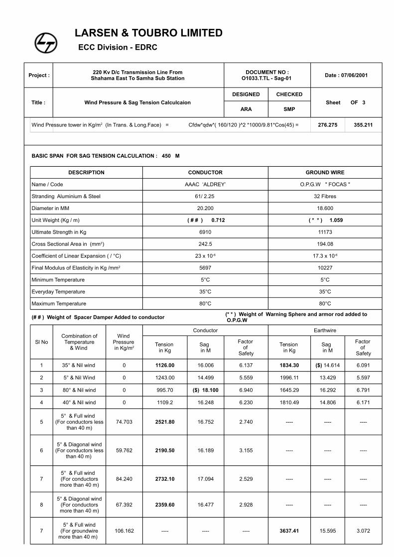
Cfdw*qdw*( 160/120 )^2 *1000/9.81*Cos(45) = 276.275 355.211
BASIC SPAN FOR SAG TENSION CALCULATION : 450 M
DESCRIPTION CONDUCTOR GROUND WIRE
Name / Code AAAC ‘ALDREY’ O.P.G.W " FOCAS "
Stranding Aluminium & Steel 61/ 2.25 32 Fibres
Diameter in MM 20.200 18.600
Unit Weight (Kg / m) ( # # ) 0.712 ( * * ) 1.059
Ultimate Strength in Kg 6910 11173
242.5 194.08
5697 10227
Minimum Temperature 5°C 5°C
Everyday Temperature 35°C 35°C
Maximum Temperature 80°C 80°C
(# # ) Weight of Spacer Damper Added to conductor
Sl No
Conductor Earthwire
1 35° & Nil wind 0 1126.00 16.006 6.137 1834.30 6.091
2 5° & Nil Wind 0 1243.00 14.499 5.559 1996.11 13.429 5.597
3 80° & Nil wind 0 995.70 ($) 18.100 6.940 1645.29 16.292 6.791
4 40° & Nil wind 0 1109.2 16.248 6.230 1810.49 14.806 6.171
5 74.703 2521.80 16.752 2.740 ---- ---- ----
6 59.762 2190.50 16.189 3.155 ---- ---- ----
7 84.240 2732.10 17.094 2.529 ---- ---- ----
8 67.392 2359.60 16.477 2.928 ---- ---- ----
7 106.162 ---- ---- ---- 3637.41 15.595 3.072
Wind Pressure tower in Kg/m2 (In Trans. & Long.Face) =
Cross Sectional Area in (mm2)
Coefficient of Linear Expansion ( / °C) 23 x 10-6 17.3 x 10⁻⁶
Final Modulus of Elasticity in Kg /mm2
(* * ) Weight of Warning Sphere and armor rod added to O.P.G.W
Combination of Temperature
& Wind
Wind Pressure in Kg/m2
Tension in Kg
Sag in M
Factor of
Safety
Tension in Kg
Sag in M
Factor of
Safety
($) 14.614
5° & Full wind (For conductors less
than 40 m)
5° & Diagonal wind(For conductors less
than 40 m)
5° & Full wind (For conductors more than 40 m)
5° & Diagonal wind(For conductors more than 40 m)
5° & Full wind(For groundwire
more than 40 m)
LARSEN & TOUBRO LIMITED ECC Division - EDRC
Project : Date : 07/06/2001
Title : Wind Pressure & Sag Tension Calculcaion
DESIGNED CHECKED
Sheet OF 3 ARA SMP
220 Kv D/c Transmission Line From Shahama East To Samha Sub Station
DOCUMENT NO : O1033.T.TL - Sag-01
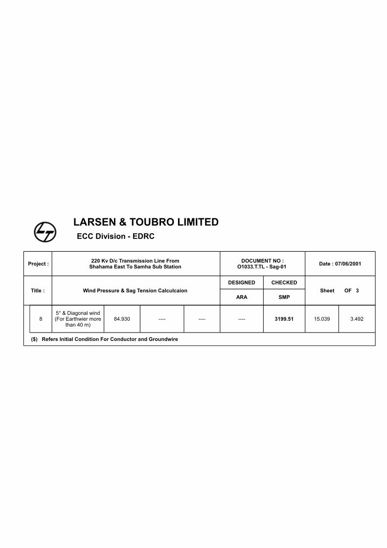
8 84.930 ---- ---- ---- 3199.51 15.039 3.492
($) Refers Initial Condition For Conductor and Groundwire
5° & Diagonal wind(For Earthwier more
than 40 m)
LARSEN & TOUBRO LIMITED
ECC DIVISION - EDRC
Project : Date : 27/07/2001
Title :
Designed Checked
Sheet OF 3 Ara Smp
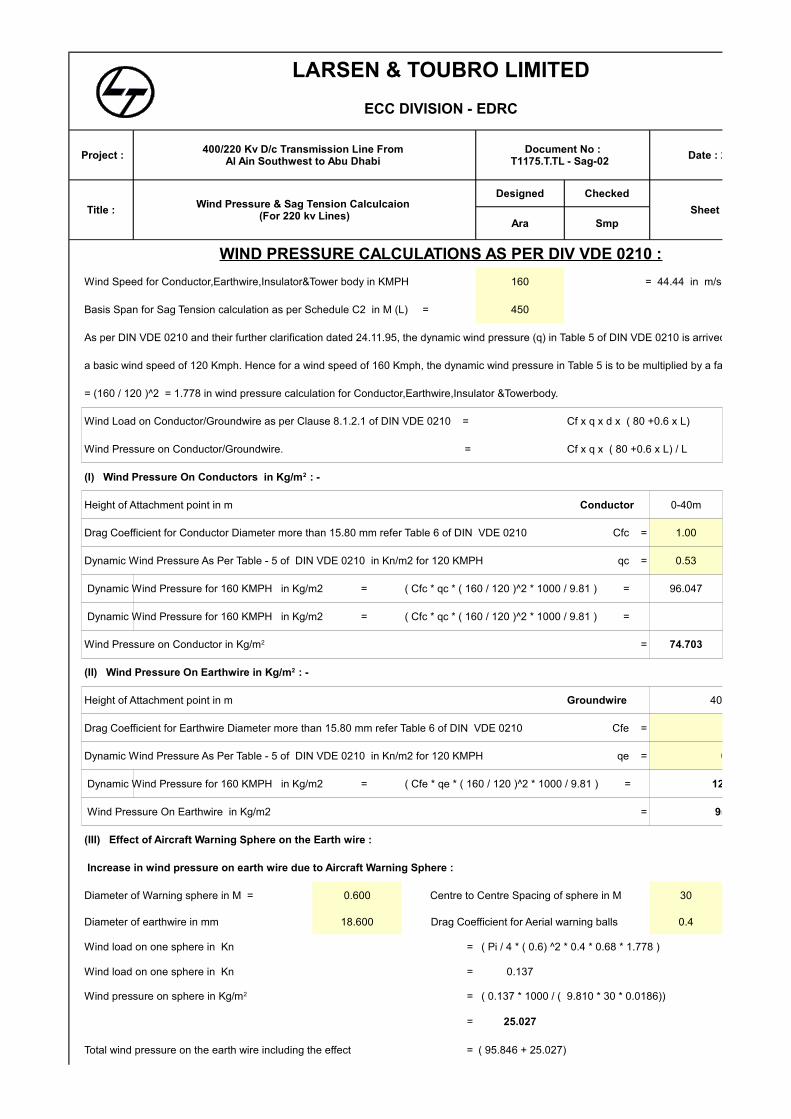
WIND PRESSURE CALCULATIONS AS PER DIV VDE 0210 :
Wind Speed for Conductor,Earthwire,Insulator&Tower body in KMPH 160 = 44.44 in m/sec
Basis Span for Sag Tension calculation as per Schedule C2 in M (L) = 450
As per DIN VDE 0210 and their further clarification dated 24.11.95, the dynamic wind pressure (q) in Table 5 of DIN VDE 0210 is arrived for
a basic wind speed of 120 Kmph. Hence for a wind speed of 160 Kmph, the dynamic wind pressure in Table 5 is to be multiplied by a factor
= (160 / 120 )^2 = 1.778 in wind pressure calculation for Conductor,Earthwire,Insulator &Towerbody.
Wind Load on Conductor/Groundwire as per Clause 8.1.2.1 of DIN VDE 0210 = Cf x q x d x ( 80 +0.6 x L)
Wind Pressure on Conductor/Groundwire. = Cf x q x ( 80 +0.6 x L) / L
Height of Attachment point in m Conductor 0-40m
Drag Coefficient for Conductor Diameter more than 15.80 mm refer Table 6 of DIN VDE 0210 Cfc = 1.00
Dynamic Wind Pressure As Per Table - 5 of DIN VDE 0210 in Kn/m2 for 120 KMPH qc = 0.53
Dynamic Wind Pressure for 160 KMPH in Kg/m2 = ( Cfc * qc * ( 160 / 120 )^2 * 1000 / 9.81 ) = 96.047
Dynamic Wind Pressure for 160 KMPH in Kg/m2 = ( Cfc * qc * ( 160 / 120 )^2 * 1000 / 9.81 ) =
= 74.703
Height of Attachment point in m Groundwire 40-100m
Drag Coefficient for Earthwire Diameter more than 15.80 mm refer Table 6 of DIN VDE 0210 Cfe = 1.00
Dynamic Wind Pressure As Per Table - 5 of DIN VDE 0210 in Kn/m2 for 120 KMPH qe = 0.68
Dynamic Wind Pressure for 160 KMPH in Kg/m2 = ( Cfe * qe * ( 160 / 120 )^2 * 1000 / 9.81 ) = 123.230
Wind Pressure On Earthwire in Kg/m2 = 95.846
(III) Effect of Aircraft Warning Sphere on the Earth wire :
Increase in wind pressure on earth wire due to Aircraft Warning Sphere :
Diameter of Warning sphere in M = 0.600 Centre to Centre Spacing of sphere in M 30
Diameter of earthwire in mm 18.600 Drag Coefficient for Aerial warning balls 0.4
Wind load on one sphere in Kn = ( Pi / 4 * ( 0.6) ^2 * 0.4 * 0.68 * 1.778 )
Wind load on one sphere in Kn = 0.137
= ( 0.137 * 1000 / ( 9.810 * 30 * 0.0186))
= 25.027
Total wind pressure on the earth wire including the effect = ( 95.846 + 25.027)
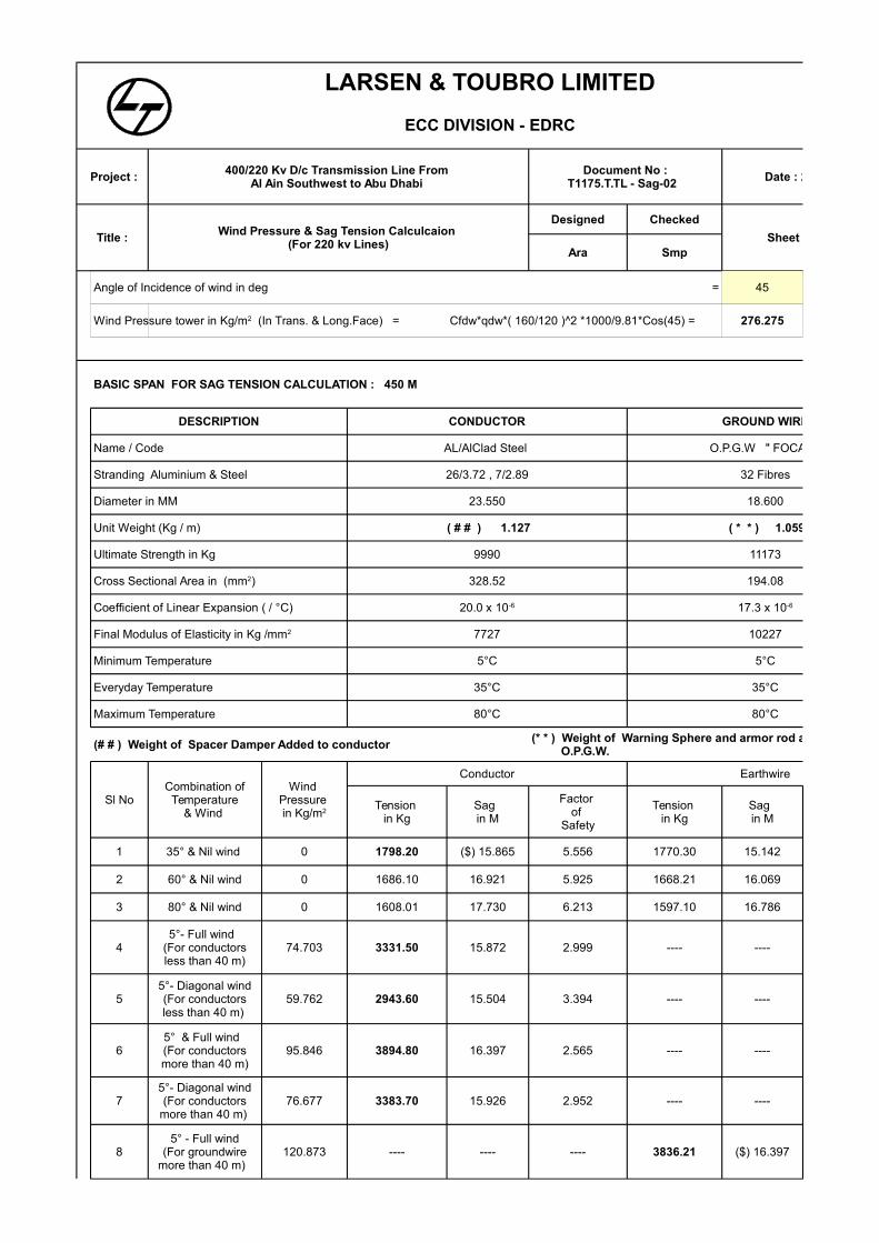
400/220 Kv D/c Transmission Line From Al Ain Southwest to Abu Dhabi
Document No :T1175.T.TL - Sag-02
Wind Pressure & Sag Tension Calculcaion (For 220 kv Lines)
(I) Wind Pressure On Conductors in Kg/m2 : -
Wind Pressure on Conductor in Kg/m2
(II) Wind Pressure On Earthwire in Kg/m2 : -
Wind pressure on sphere in Kg/m2
LARSEN & TOUBRO LIMITED
ECC DIVISION - EDRC
Project : Date : 27/07/2001
Title :
Designed Checked
Sheet OF 3 Ara Smp
400/220 Kv D/c Transmission Line From Al Ain Southwest to Abu Dhabi
Document No :T1175.T.TL - Sag-02
Wind Pressure & Sag Tension Calculcaion (For 220 kv Lines)
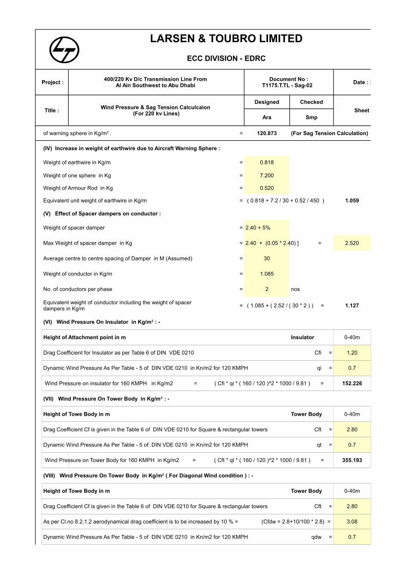
= 120.873 (For Sag Tension Calculation)
(IV) Increase in weight of earthwire due to Aircraft Warning Sphere :
Weight of earthwire in Kg/m = 0.818
Weight of one sphere in Kg = 7.200
Weight of Armour Rod in Kg = 0.520
Equivalent unit weight of earthwire in Kg/m = ( 0.818 + 7.2 / 30 + 0.52 / 450 ) 1.059
(V) Effect of Spacer dampers on conductor :
Weight of spacer damper = 2.40 + 5%
Max Weight of spacer damper in Kg = 2.40 + (0.05 * 2.40) ] = 2.520
Average centre to centre spacing of Damper in M (Assumed) = 30
Weight of conductor in Kg/m = 1.085
No. of conductors per phase = 2 nos
= ( 1.085 + ( 2.52 / ( 30 * 2 ) ) = 1.127
Height of Attachment point in m Insulator 0-40m
Drag Coefficient for Insulator as per Table 6 of DIN VDE 0210 Cfi = 1.20
Dynamic Wind Pressure As Per Table - 5 of DIN VDE 0210 in Kn/m2 for 120 KMPH qi = 0.7
Wind Pressure on insulator for 160 KMPH in Kg/m2 = ( Cfi * qi * ( 160 / 120 )^2 * 1000 / 9.81 ) = 152.226
Height of Towe Body in m Tower Body 0-40m
Drag Coefficient Cf is given in the Table 6 of DIN VDE 0210 for Square & rectangular towers Cft = 2.80
Dynamic Wind Pressure As Per Table - 5 of DIN VDE 0210 in Kn/m2 for 120 KMPH qt = 0.7
Wind Pressure on Tower Body for 160 KMPH in Kg/m2 = ( Cft * qt * ( 160 / 120 )^2 * 1000 / 9.81 ) = 355.193
Height of Towe Body in m Tower Body 0-40m
Drag Coefficient Cf is given in the Table 6 of DIN VDE 0210 for Square & rectangular towers Cft = 2.80
As per Cl.no 8.2.1.2 aerodynamical drag coefficient is to be increased by 10 % = (Cfdw = 2.8+10/100 * 2.8) = 3.08
Dynamic Wind Pressure As Per Table - 5 of DIN VDE 0210 in Kn/m2 for 120 KMPH qdw = 0.7
of warning sphere in Kg/m2 .
Equivalent weight of conductor including the weight of spacer dampers in Kg/m
(VI) Wind Pressure On Insulator in Kg/m2 : -
(VII) Wind Pressure On Tower Body in Kg/m2 : -
(VIII) Wind Pressure On Tower Body in Kg/m2 ( For Diagonal Wind condition ) : -
LARSEN & TOUBRO LIMITED
ECC DIVISION - EDRC
Project : Date : 27/07/2001
Title :
Designed Checked
Sheet OF 3 Ara Smp
400/220 Kv D/c Transmission Line From Al Ain Southwest to Abu Dhabi
Document No :T1175.T.TL - Sag-02
Wind Pressure & Sag Tension Calculcaion (For 220 kv Lines)
Angle of Incidence of wind in deg = 45
Cfdw*qdw*( 160/120 )^2 *1000/9.81*Cos(45) = 276.275
BASIC SPAN FOR SAG TENSION CALCULATION : 450 M
DESCRIPTION CONDUCTOR GROUND WIRE
Name / Code AL/AlClad Steel O.P.G.W " FOCAS "
Stranding Aluminium & Steel 26/3.72 , 7/2.89 32 Fibres
Diameter in MM 23.550 18.600
Unit Weight (Kg / m) ( # # ) 1.127 ( * * ) 1.059
Ultimate Strength in Kg 9990 11173
328.52 194.08
7727 10227
Minimum Temperature 5°C 5°C
Everyday Temperature 35°C 35°C
Maximum Temperature 80°C 80°C
(# # ) Weight of Spacer Damper Added to conductor
Sl No
Conductor Earthwire
1 35° & Nil wind 0 1798.20 ($) 15.865 5.556 1770.30 15.142
2 60° & Nil wind 0 1686.10 16.921 5.925 1668.21 16.069
3 80° & Nil wind 0 1608.01 17.730 6.213 1597.10 16.786
4 74.703 3331.50 15.872 2.999 ---- ----
5 59.762 2943.60 15.504 3.394 ---- ----
6 95.846 3894.80 16.397 2.565 ---- ----
7 76.677 3383.70 15.926 2.952 ---- ----
8 120.873 ---- ---- ---- 3836.21 ($) 16.397
Wind Pressure tower in Kg/m2 (In Trans. & Long.Face) =
Cross Sectional Area in (mm2)
Coefficient of Linear Expansion ( / °C) 20.0 x 10⁻⁶ 17.3 x 10⁻⁶
Final Modulus of Elasticity in Kg /mm2
(* * ) Weight of Warning Sphere and armor rod added to O.P.G.W.
Combination of Temperature
& Wind
Wind Pressure in Kg/m2
Tension in Kg
Sag in M
Factor of
Safety
Tension in Kg
Sag in M
5°- Full wind (For conductors less than 40 m)
5°- Diagonal wind(For conductors less than 40 m)
5° & Full wind (For conductors more than 40 m)
5°- Diagonal wind(For conductors
more than 40 m)
5° - Full wind(For groundwire
more than 40 m)
LARSEN & TOUBRO LIMITED
ECC DIVISION - EDRC
Project : Date : 27/07/2001
Title :
Designed Checked
Sheet OF 3 Ara Smp
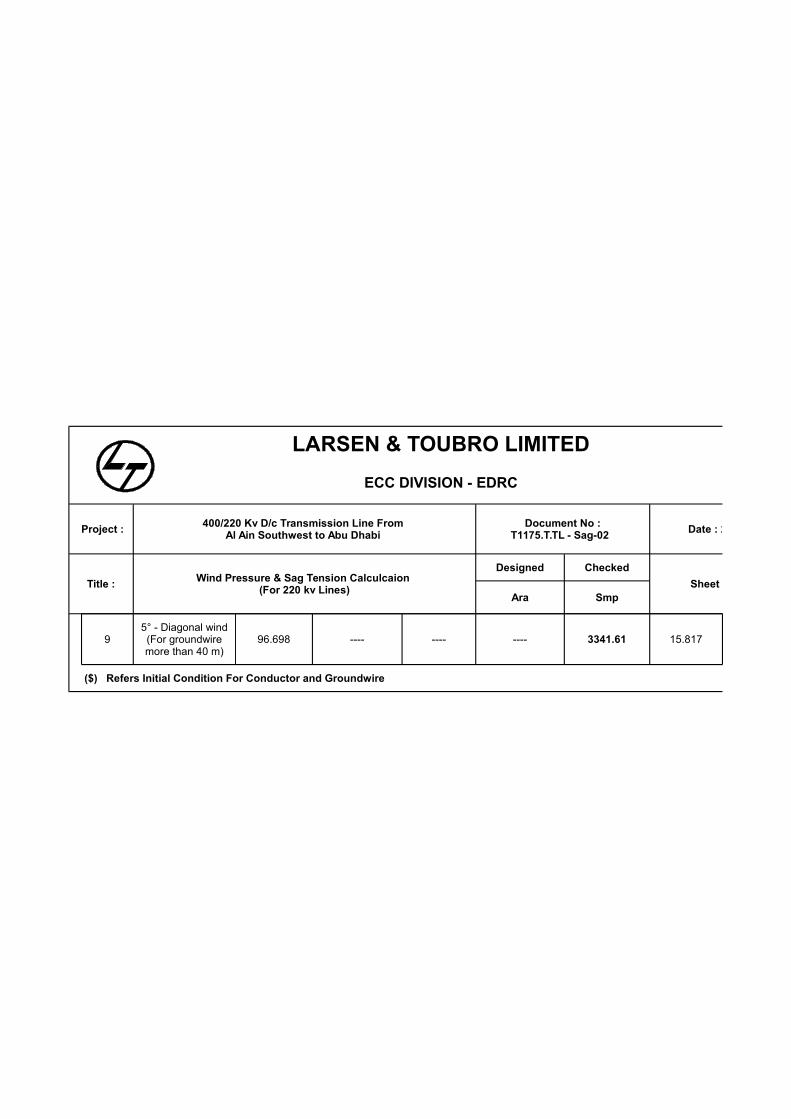
400/220 Kv D/c Transmission Line From Al Ain Southwest to Abu Dhabi
Document No :T1175.T.TL - Sag-02
Wind Pressure & Sag Tension Calculcaion (For 220 kv Lines)
9 96.698 ---- ---- ---- 3341.61 15.817
($) Refers Initial Condition For Conductor and Groundwire
5° - Diagonal wind(For groundwire more than 40 m)

LARSEN & TOUBRO LIMITED
ECC DIVISION - EDRC
Date : 27/07/2001
Sheet OF 3
WIND PRESSURE CALCULATIONS AS PER DIV VDE 0210 :
= 44.44 in m/sec
As per DIN VDE 0210 and their further clarification dated 24.11.95, the dynamic wind pressure (q) in Table 5 of DIN VDE 0210 is arrived for
a basic wind speed of 120 Kmph. Hence for a wind speed of 160 Kmph, the dynamic wind pressure in Table 5 is to be multiplied by a factor
40-100m
1.00
0.68
123.230
95.846
40-100m
1.00
0.68
123.230
95.846
LARSEN & TOUBRO LIMITED
ECC DIVISION - EDRC
Date : 27/07/2001
Sheet OF 3
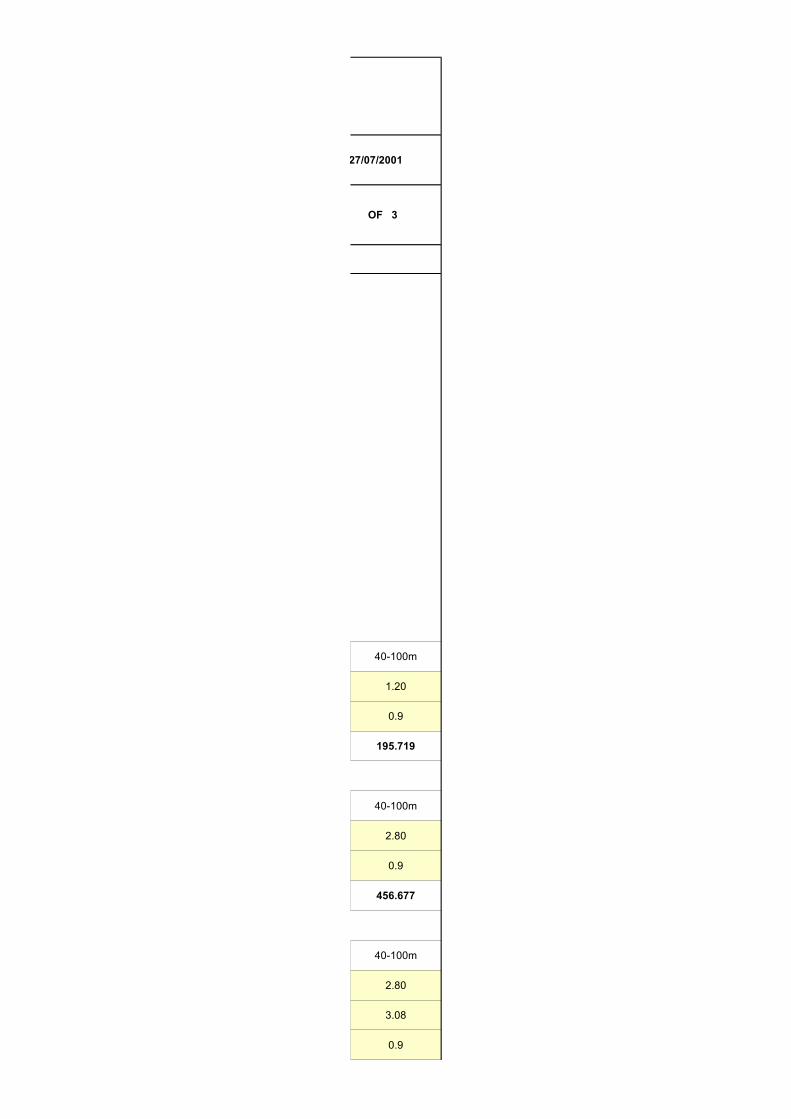
40-100m
1.20
0.9
195.719
40-100m
2.80
0.9
456.677
40-100m
2.80
3.08
0.9
LARSEN & TOUBRO LIMITED
ECC DIVISION - EDRC
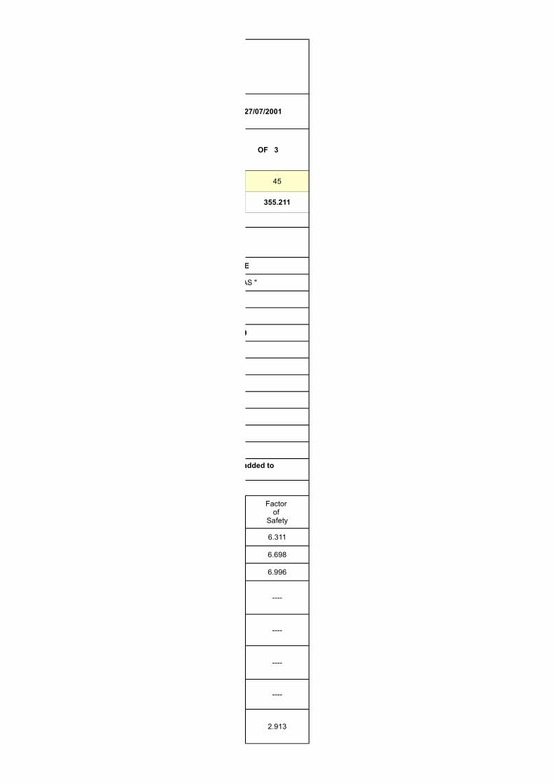
Date : 27/07/2001
Sheet OF 3
45
355.211
GROUND WIRE
O.P.G.W " FOCAS "
32 Fibres
18.600
( * * ) 1.059
11173
194.08
10227
5°C
35°C
80°C
Earthwire
6.311
6.698
6.996
----
----
----
----
2.913
17.3 x 10⁻⁶
(* * ) Weight of Warning Sphere and armor rod added to O.P.G.W.
Factor of
Safety
LARSEN & TOUBRO LIMITED
ECC DIVISION - EDRC
Date : 27/07/2001
Sheet OF 3
3.344