Embed Size (px)
Citation preview
CIAOGREEN
C.S.I.
EN INSTALLER AND USER MANUAL
ES MANUAL DE INSTALACIÓN Y USO
PT MANUAL PARA INSTALAÇÃO E USO
HU TELEPÍT I ÉS FELHASZNÁLÓI KÉZIKÖNYV
DE HANDBUCH FÜR DIE MONTAGE UND BENUTZUNG
SL NAVODILA ZA VGRADITEV, PRIKLJU ITEV IN UPORABO
HR PRIRU NIK ZA MONTAŽU I KORIŠTENJE
SRB PRIRU NIK ZA MONTAŽU I KORIŠ ENJE
MANUAL DE INSTALARE SI UTILIZARERO
NÁVOD NA INSTALACI A POUŽITÍ CZ
TR TES SATÇI VE KULLANICI KILAVUZU
PL INSTRUKCJA OBS UGI, INSTALACJI I KONSERWACJI KOT A GAZOWEGO
2
CIAO GREEN C.S.I.
06940694CL6033
06940694CL6033
Ciao Green C.S.I. boilers comply with the essential requirements of the following Directives:- Gas Appliance Directive 2009/142/EC- Ef ciency Directive 92/42/EEC - Electromagnetic Compatibility Directive 2004/108/EC- Low Voltage Directive 2006/95/EC- Regulation 677 for condensation boilers
and therefore bears the EC marking
La caldera Ciao Green C.S.I. es conforme a los requisitos fundamentales de las siguientes Directivas:- Directiva Gas 2009/142/CE- Directiva Rendimientos 92/42/CEE - Directiva Compatibilidad Electromagnética 2004/108/CE- Directiva Baja Tensión 2006/95/CE- Norma 677 para calderas de condensación
por lo tanto posee el Marcado CE
06940694CL6033
A caldeira Ciao Green C.S.I. está em conformidade com os requisitos essenciais das seguintes Directivas:- Directiva de gás 2009/142/CE- Directiva de Rendimentos 92/42/CEE - Directiva de Compatibilidade Electromagnética 2004/108/CE- Directiva Baixa tensão 2006/95/CE- Regulação 677 para caldeiras de condensação
portanto, é titular da marcação CE
06940694CL6033
A Ciao Green C.S.I. kazán megfelel az alábbi irányelvek alapvet követelményeinek:- Gázüzem berendezésekr l szóló 2009/142/EK irányelv- Melegvízkazánokról szóló 92/42/EGK irányelv - Elektromágneses összeférhet ségr l szóló 2004/108/EK irányelv- Kisfeszültség berendezésekr l szóló 2006/95/EK irányelv- Kondenzációs kazánokra vonatkozó 677 sz. szabvány
továbbá CE jelzéssel rendelkezik
06940694CL6033
Der Kessel Ciao Green C.S.I. entspricht den wesentlichen Anforderungen der folgenden Richtlinien:- Gas-Richtlinie 2009/142/EG- Wirkungsgradrichtlinie 92/42/EWG - Richtlinie über die elektromagnetische Verträglichkeit 2004/108/EG- Niederspannungsrichtlinie 2006/95/EG- Normen für Kondensationskessel 677
und besitzt daher die CE-Kennung
EN
ES
PT
HU
DE
06940694CL6033
ROCentrala Ciao Green C.S.I. este în conformitate cu cerin ele esen iale ale urm toarelor Directive:- Directiva de Gaz 2009/142/CE- Directiva de Randament 92/42/CEE- Directiva de Compatibilitate Electromagnetic 2004/108/CE- Directiva de Joas Tensiune 2006/95/CE- Regulamentul 677 referitor la boilerele cu condensare
astfel, poart marca CE
3
CIAO GREEN C.S.I.
06940694CL6033
Kotel Ciao Green C.S.I. je skladen z bistvenimi zahtevami naslednjih direktiv:- Direktiva o napravah na plinsko gorivo 2009/142/ES- Direktiva o izkoristkih 92/42/EGS - Direktiva o elektromagnetni združljivosti 2004/108/ES- Direktiva o nizkonapetostni opremi 2006/95/ES- Uredba o kondenzacijskih kotlih 677
zato je nosilec CE oznake
06940694CL6033
Kotao Ciao Green C.S.I. u skladu je s temeljnim zahtjevima iz slijede ih Direktiva:- Direktiva za plin 2009/142/CE- Direktiva o u incima 92/42/CEE - Direktiva o elektromagnetskoj kompatibilnosti 2004/108/CE- Direktiva o niskom naponu 2006/95/CE- Norme za kondenzacijske kotlove 677
stoga nosi oznaku CE
06940694CL6033
Kotao Ciao Green C.S.I. je usaglašen sa osnovnim zahtevima slede ih direktiva:- Direktivom za plinske ure aje 2009/142/EC- Direktivom o e kasnosti 92/42/EEC - Direktivom o elektromagnetnoj kompatibilnosti 2004/108/EC- Direktivom za niskonaponske ure aje 2006/95/EC- Norme za kondenzacione kotlove 677
zbog ega je nosilac CE oznake
SL
HR
SRB
CZ
06940694CL6033
Ciao Green C.S.I. - kotle jsou v souladu se záladními požadavky následujících sm rnic:- Sm rnice pro plynová za ízení 2009/142/CE- Sm rnice o výkonnosti a ú innosti kotl 92/42/CEE- Sm rnice o elektromagnetické kompatibilit 2004/108/CE- Sm rnice o nízkém nap tí 2006/95/CE- Kotle Prohlášení kondenza ní EN 677
Proto je nositelem ozna ení CE.
06940694CL6033
Ciao Green C.S.I. kazan , a a daki Yönetmelikler taraf ndan öngörülen gerekliliklere uygundur:- 2009/142/CE gaz yönetmeli i- 92/42/CEE Performans yönetmeli i - 2004/108/CE Elektromanyetik Uyumluluk Yönetmeli i- 2006/95/CE Alçak gerilim yönetmeli i- EN 677 yo u mal kazan düzenlemesi
Bu nedenle CE markas na sahiptir
TR
06940694CL6033
Ciao Green C.S.I. spe nia podstawowe wymagania nast puj cych rozporz dze :- Rozporz dzenie dot. gazu 2009/142/EWG- Rozporz dzenie dot. sprawno ci 92/42/EWG- Rozporz dzenie dot. zgodno ci elektromagnetycznej 2004/108/EWG- Rozporz dzenie dot. niskiego napi cia 2006/95/EWG- Rozporz dzenie dot. kot ów kondensacyjnych EN 677
I w zwi zku z powy szym posiada znak CE.
PL
4
CIAO GREEN C.S.I.
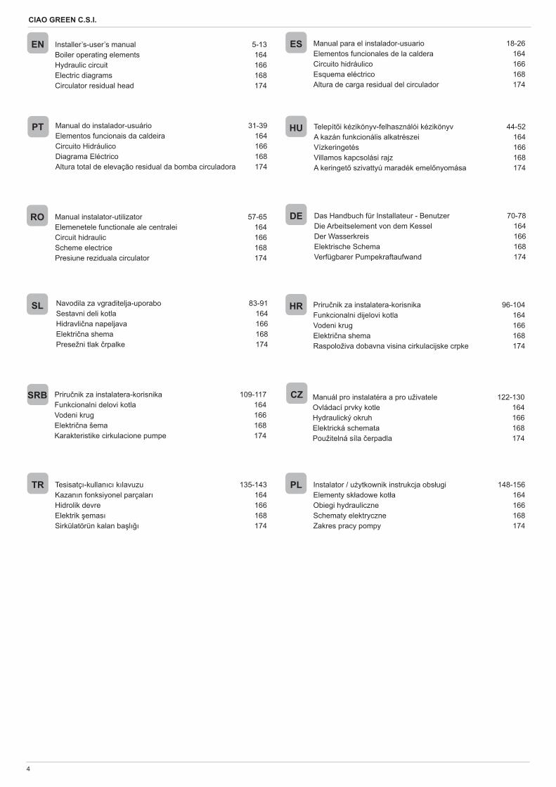
Installer’s-user’s manual 5-13Boiler operating elements 164Hydraulic circuit 166Electric diagrams 168Circulator residual head 174
EN ES
HU
DE
SL HR
Manual para el instalador-usuario 18-26Elementos funcionales de la caldera 164Circuito hidráulico 166Esquema eléctrico 168Altura de carga residual del circulador 174
Manual do instalador-usuário 31-39Elementos funcionais da caldeira 164Circuito Hidráulico 166Diagrama Eléctrico 168Altura total de elevação residual da bomba circuladora 174
Telepít i kézikönyv-felhasználói kézikönyv 44-52A kazán funkcionális alkatrészei 164Vízkeringetés 166Villamos kapcsolási rajz 168A keringet szivattyú maradék emel nyomása 174
Das Handbuch für Installateur - Benutzer 70-78Die Arbeitselement von dem Kessel 164Der Wasserkreis 166Elektrische Schema 168Verfügbarer Pumpekraftaufwand 174
Navodila za vgraditelja-uporabo 83-91Sestavni deli kotla 164Hidravli na napeljava 166Elektri na shema 168Presežni tlak rpalke 174
Priru nik za instalatera-korisnika 96-104Funkcionalni dijelovi kotla 164Vodeni krug 166Elektri na shema 168Raspoloživa dobavna visina cirkulacijske crpke 174
Priru nik za instalatera-korisnika 109-117Funkcionalni delovi kotla 164Vodeni krug 166Elektri na šema 168Karakteristike cirkulacione pumpe 174
SRB
RO Manual instalator-utilizator 57-65Elemenetele functionale ale centralei 164Circuit hidraulic 166Scheme electrice 168Presiune reziduala circulator 174
PT
CZ Manuál pro instalatéra a pro uživatele 122-130Ovládací prvky kotle 164Hydraulický okruh 166Elektrická schemata 168Použitelná síla erpadla 174
Tesisatç -kullan c k lavuzu 135-143Kazan n fonksiyonel parçalar 164Hidrolik devre 166Elektrik emas 168Sirkülatörün kalan ba l 174
Instalator / u ytkownik instrukcja obs ugi 148-156Elementy sk adowe kot a 164Obiegi hydrauliczne 166Schematy elektryczne 168Zakres pracy pompy 174
TR PL
5
ENGLISH
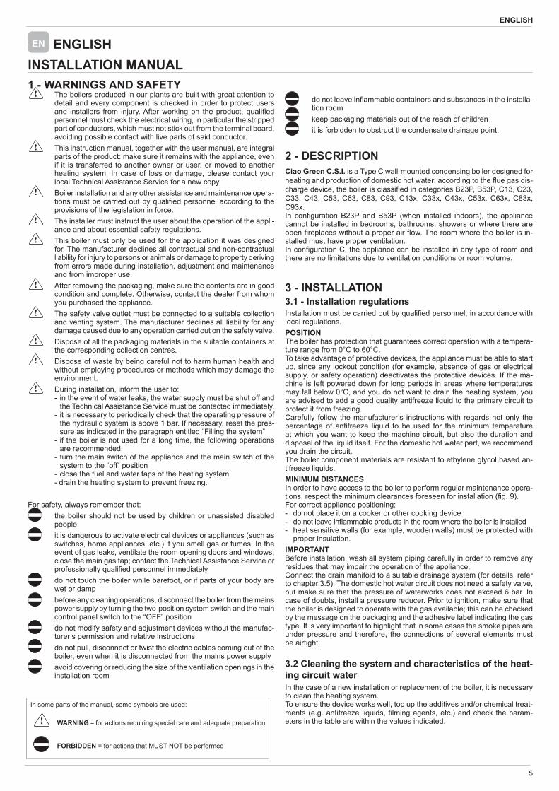
1 - WARNINGS AND SAFETY The boilers produced in our plants are built with great attention to
detail and every component is checked in order to protect users and installers from injury. After working on the product, quali ed personnel must check the electrical wiring, in particular the stripped part of conductors, which must not stick out from the terminal board, avoiding possible contact with live parts of said conductor.
This instruction manual, together with the user manual, are integral parts of the product: make sure it remains with the appliance, even if it is transferred to another owner or user, or moved to another heating system. In case of loss or damage, please contact your local Technical Assistance Service for a new copy.
Boiler installation and any other assistance and maintenance opera-tions must be carried out by quali ed personnel according to the provisions of the legislation in force.
The installer must instruct the user about the operation of the appli-ance and about essential safety regulations.
This boiler must only be used for the application it was designed for. The manufacturer declines all contractual and non-contractual liability for injury to persons or animals or damage to property deriving from errors made during installation, adjustment and maintenance and from improper use.
After removing the packaging, make sure the contents are in good condition and complete. Otherwise, contact the dealer from whom you purchased the appliance.
The safety valve outlet must be connected to a suitable collection and venting system. The manufacturer declines all liability for any damage caused due to any operation carried out on the safety valve.
Dispose of all the packaging materials in the suitable containers at the corresponding collection centres.
Dispose of waste by being careful not to harm human health and without employing procedures or methods which may damage the environment.
During installation, inform the user to: - in the event of water leaks, the water supply must be shut off and
the Technical Assistance Service must be contacted immediately. - it is necessary to periodically check that the operating pressure of
the hydraulic system is above 1 bar. If necessary, reset the pres-sure as indicated in the paragraph entitled “Filling the system”
- if the boiler is not used for a long time, the following operations are recommended:
- turn the main switch of the appliance and the main switch of the system to the “off” position
- close the fuel and water taps of the heating system - drain the heating system to prevent freezing.
For safety, always remember that: the boiler should not be used by children or unassisted disabled
people it is dangerous to activate electrical devices or appliances (such as
switches, home appliances, etc.) if you smell gas or fumes. In the event of gas leaks, ventilate the room opening doors and windows; close the main gas tap; contact the Technical Assistance Service or professionally quali ed personnel immediately
do not touch the boiler while barefoot, or if parts of your body are wet or damp
before any cleaning operations, disconnect the boiler from the mains power supply by turning the two-position system switch and the main control panel switch to the “OFF” position
do not modify safety and adjustment devices without the manufac-turer’s permission and relative instructions
do not pull, disconnect or twist the electric cables coming out of the boiler, even when it is disconnected from the mains power supply
avoid covering or reducing the size of the ventilation openings in the installation room
INSTALLATION MANUALEN ENGLISH
do not leave in ammable containers and substances in the installa-tion room
keep packaging materials out of the reach of children it is forbidden to obstruct the condensate drainage point.
2 - DESCRIPTIONCiao Green C.S.I. is a Type C wall-mounted condensing boiler designed for heating and production of domestic hot water: according to the ue gas dis-charge device, the boiler is classi ed in categories B23P, B53P, C13, C23, C33, C43, C53, C63, C83, C93, C13x, C33x, C43x, C53x, C63x, C83x, C93x.In con guration B23P and B53P (when installed indoors), the appliance cannot be installed in bedrooms, bathrooms, showers or where there are open replaces without a proper air ow. The room where the boiler is in-stalled must have proper ventilation. In con guration C, the appliance can be installed in any type of room and there are no limitations due to ventilation conditions or room volume.
3 - INSTALLATION3.1 - Installation regulationsInstallation must be carried out by quali ed personnel, in accordance with local regulations.POSITIONThe boiler has protection that guarantees correct operation with a tempera-ture range from 0°C to 60°C.To take advantage of protective devices, the appliance must be able to start up, since any lockout condition (for example, absence of gas or electrical supply, or safety operation) deactivates the protective devices. If the ma-chine is left powered down for long periods in areas where temperatures may fall below 0°C, and you do not want to drain the heating system, you are advised to add a good quality antifreeze liquid to the primary circuit to protect it from freezing. Carefully follow the manufacturer’s instructions with regards not only the percentage of antifreeze liquid to be used for the minimum temperature at which you want to keep the machine circuit, but also the duration and disposal of the liquid itself. For the domestic hot water part, we recommend you drain the circuit.The boiler component materials are resistant to ethylene glycol based an-tifreeze liquids. MINIMUM DISTANCESIn order to have access to the boiler to perform regular maintenance opera-tions, respect the minimum clearances foreseen for installation ( g. 9).For correct appliance positioning:- do not place it on a cooker or other cooking device- do not leave in ammable products in the room where the boiler is installed- heat sensitive walls (for example, wooden walls) must be protected with
proper insulation.IMPORTANTBefore installation, wash all system piping carefully in order to remove any residues that may impair the operation of the appliance.Connect the drain manifold to a suitable drainage system (for details, refer to chapter 3.5). The domestic hot water circuit does not need a safety valve, but make sure that the pressure of waterworks does not exceed 6 bar. In case of doubts, install a pressure reducer. Prior to ignition, make sure that the boiler is designed to operate with the gas available; this can be checked by the message on the packaging and the adhesive label indicating the gas type. It is very important to highlight that in some cases the smoke pipes are under pressure and therefore, the connections of several elements must be airtight.
3.2 Cleaning the system and characteristics of the heat-ing circuit waterIn the case of a new installation or replacement of the boiler, it is necessary to clean the heating system. To ensure the device works well, top up the additives and/or chemical treat-ments (e.g. antifreeze liquids, lming agents, etc.) and check the param-eters in the table are within the values indicated.
In some parts of the manual, some symbols are used:
WARNING = for actions requiring special care and adequate preparation
FORBIDDEN = for actions that MUST NOT be performed
6
CIAO GREEN C.S.I.
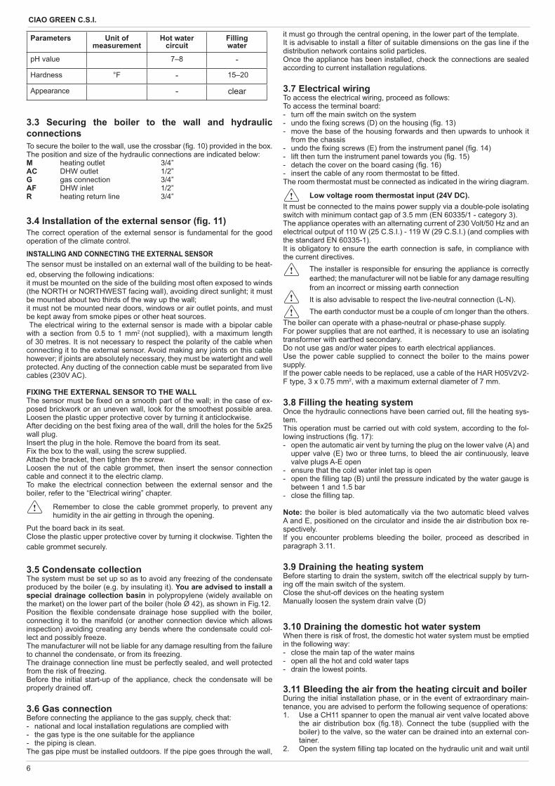
Parameters Unit of measurement
Hot watercircuit
Fillingwater
pH value 7–8 -
Hardness °F - 15–20
Appearance - clear
3.3 Securing the boiler to the wall and hydraulic connectionsTo secure the boiler to the wall, use the crossbar ( g. 10) provided in the box. The position and size of the hydraulic connections are indicated below:M heating outlet 3/4”AC DHW outlet 1/2”G gas connection 3/4”AF DHW inlet 1/2”R heating return line 3/4”
3.4 Installation of the external sensor ( g. 11) The correct operation of the external sensor is fundamental for the good operation of the climate control.
INSTALLING AND CONNECTING THE EXTERNAL SENSORThe sensor must be installed on an external wall of the building to be heat-ed, observing the following indications:it must be mounted on the side of the building most often exposed to winds (the NORTH or NORTHWEST facing wall), avoiding direct sunlight; it must be mounted about two thirds of the way up the wall;it must not be mounted near doors, windows or air outlet points, and must be kept away from smoke pipes or other heat sources. The electrical wiring to the external sensor is made with a bipolar cable with a section from 0.5 to 1 mm2 (not supplied), with a maximum length of 30 metres. It is not necessary to respect the polarity of the cable when connecting it to the external sensor. Avoid making any joints on this cable however; if joints are absolutely necessary, they must be watertight and well protected. Any ducting of the connection cable must be separated from live cables (230V AC).
FIXING THE EXTERNAL SENSOR TO THE WALLThe sensor must be xed on a smooth part of the wall; in the case of ex-posed brickwork or an uneven wall, look for the smoothest possible area. Loosen the plastic upper protective cover by turning it anticlockwise. After deciding on the best xing area of the wall, drill the holes for the 5x25 wall plug.Insert the plug in the hole. Remove the board from its seat.Fix the box to the wall, using the screw supplied. Attach the bracket, then tighten the screw.Loosen the nut of the cable grommet, then insert the sensor connection cable and connect it to the electric clamp. To make the electrical connection between the external sensor and the boiler, refer to the “Electrical wiring” chapter.
Remember to close the cable grommet properly, to prevent any humidity in the air getting in through the opening.
Put the board back in its seat.Close the plastic upper protective cover by turning it clockwise. Tighten the cable grommet securely.
3.5 Condensate collectionThe system must be set up so as to avoid any freezing of the condensate produced by the boiler (e.g. by insulating it). You are advised to install a special drainage collection basin in polypropylene (widely available on the market) on the lower part of the boiler (hole Ø 42), as shown in Fig.12.Position the exible condensate drainage hose supplied with the boiler, connecting it to the manifold (or another connection device which allows inspection) avoiding creating any bends where the condensate could col-lect and possibly freeze.The manufacturer will not be liable for any damage resulting from the failure to channel the condensate, or from its freezing.The drainage connection line must be perfectly sealed, and well protected from the risk of freezing.Before the initial start-up of the appliance, check the condensate will be properly drained off.
3.6 Gas connectionBefore connecting the appliance to the gas supply, check that:- national and local installation regulations are complied with- the gas type is the one suitable for the appliance- the piping is clean.The gas pipe must be installed outdoors. If the pipe goes through the wall,
it must go through the central opening, in the lower part of the template.It is advisable to install a lter of suitable dimensions on the gas line if the distribution network contains solid particles.Once the appliance has been installed, check the connections are sealed according to current installation regulations.
3.7 Electrical wiringTo access the electrical wiring, proceed as follows:To access the terminal board:- turn off the main switch on the system- undo the xing screws (D) on the housing ( g. 13)- move the base of the housing forwards and then upwards to unhook it
from the chassis- undo the xing screws (E) from the instrument panel ( g. 14)- lift then turn the instrument panel towards you ( g. 15)- detach the cover on the board casing ( g. 16)- insert the cable of any room thermostat to be tted. The room thermostat must be connected as indicated in the wiring diagram.
Low voltage room thermostat input (24V DC).It must be connected to the mains power supply via a double-pole isolating switch with minimum contact gap of 3.5 mm (EN 60335/1 - category 3). The appliance operates with an alternating current of 230 Volt/50 Hz and an electrical output of 110 W (25 C.S.I.) - 119 W (29 C.S.I.) (and complies with the standard EN 60335-1).It is obligatory to ensure the earth connection is safe, in compliance with the current directives.
The installer is responsible for ensuring the appliance is correctly earthed; the manufacturer will not be liable for any damage resulting from an incorrect or missing earth connection
It is also advisable to respect the live-neutral connection (L-N). The earth conductor must be a couple of cm longer than the others.
The boiler can operate with a phase-neutral or phase-phase supply.For power supplies that are not earthed, it is necessary to use an isolating transformer with earthed secondary.Do not use gas and/or water pipes to earth electrical appliances. Use the power cable supplied to connect the boiler to the mains power supply.If the power cable needs to be replaced, use a cable of the HAR H05V2V2-F type, 3 x 0.75 mm2, with a maximum external diameter of 7 mm.
3.8 Filling the heating systemOnce the hydraulic connections have been carried out, ll the heating sys-tem. This operation must be carried out with cold system, according to the fol-lowing instructions ( g. 17):- open the automatic air vent by turning the plug on the lower valve (A) and
upper valve (E) two or three turns, to bleed the air continuously, leave valve plugs A-E open
- ensure that the cold water inlet tap is open- open the lling tap (B) until the pressure indicated by the water gauge is
between 1 and 1.5 bar- close the lling tap.
Note: the boiler is bled automatically via the two automatic bleed valves A and E, positioned on the circulator and inside the air distribution box re-spectively.If you encounter problems bleeding the boiler, proceed as described in paragraph 3.11.
3.9 Draining the heating systemBefore starting to drain the system, switch off the electrical supply by turn-ing off the main switch of the system.Close the shut-off devices on the heating systemManually loosen the system drain valve (D)
3.10 Draining the domestic hot water systemWhen there is risk of frost, the domestic hot water system must be emptied in the following way:- close the main tap of the water mains- open all the hot and cold water taps- drain the lowest points.
3.11 Bleeding the air from the heating circuit and boilerDuring the initial installation phase, or in the event of extraordinary main-tenance, you are advised to perform the following sequence of operations:1. Use a CH11 spanner to open the manual air vent valve located above
the air distribution box ( g.18). Connect the tube (supplied with the boiler) to the valve, so the water can be drained into an external con-tainer.
2. Open the system lling tap located on the hydraulic unit and wait until
7
ENGLISH
water begins to drain out of the valve.3. Switch on the electricity supply to the boiler, leaving the gas tap turned off.4. Activate a heat request via the room thermostat or the remote control
panel, so that the 3-way valve goes into heating mode.5. Activate a DHW request as follows: instantaneous boilers: open a tap, for 30 seconds every minute so
that the three-way valve switches from heating to domestic hot water and vice versa about ten times. In this situation, the boiler will go into alarm mode due to the absence of gas, so it must be reset every time this happens.
heat-only boilers connected to an external storage tank: activate the thermostat on the storage tank;
6. Carry on with the sequence until only water leaks out of the manual air vent valve, and the air ow has stopped. Close the manual air vent valve.
7. Check the system pressure level is correct (the ideal level is 1 bar).8. Turn off the system lling tap.9. Turn on the gas tap and ignite the boiler.
3.12 Flue gas discharge and air suctionObserve local legislation regarding ue gas discharge.Flue gases are discharged from a centrifugal fan located inside the combus-tion chamber and the control board constantly checks that this is working correctly. The boiler is supplied without the ue gas discharge/air suction kit, since it is possible to use the accessories for appliance with a forced draught sealed chamber that better adapts to the installation characteristics. For ue gas extraction and the restoration of boiler combustion air, it is essential to only use certi ed piping. Connection must be carried out correctly as indicated in the instructions supplied as standard with the ue gas accessories. Multiple appliances can be connected to a single smoke pipe provided that each is a sealed chamber-type appliance. The boiler is a Type C appliance (sealed chamber), and must therefore have a safe connection to the ue gas discharge pipe and to the combustion air suction pipe; these both carry their contents outside, and are essential for the operation of the appliance.
POSSIBLE OUTLET CONFIGURATIONS (FIG. 24)B23P/B53P Suction indoors and discharge outdoorsC13-C13x Discharge via concentric wall outlet. The pipes may leave the boiler independently, but the outlets must be concentric or suf ciently close together to be subjected to similar wind conditions (within 50 cm)C23 Discharge via concentric outlet in common smoke pipe (suction and discharge in the same pipe)C33-C33x Discharge via concentric roof outlet. Outlets as for C13C43-C43x Discharge and suction in common separate smoke pipes, but subjected to similar wind conditionsC53-C53x Separate discharge and suction lines on wall or roof and in areas with different pressures. The discharge and suction lines must never be positioned on opposite wallsC63-C63x Discharge and suction lines using pipes marketed and certi ed separately (1856/1)C83-C83x Discharge via single or common smoke pipe and wall suction lineC93-C93x Discharge on roof (similar to C33) and air suction from a single existing smoke pipe
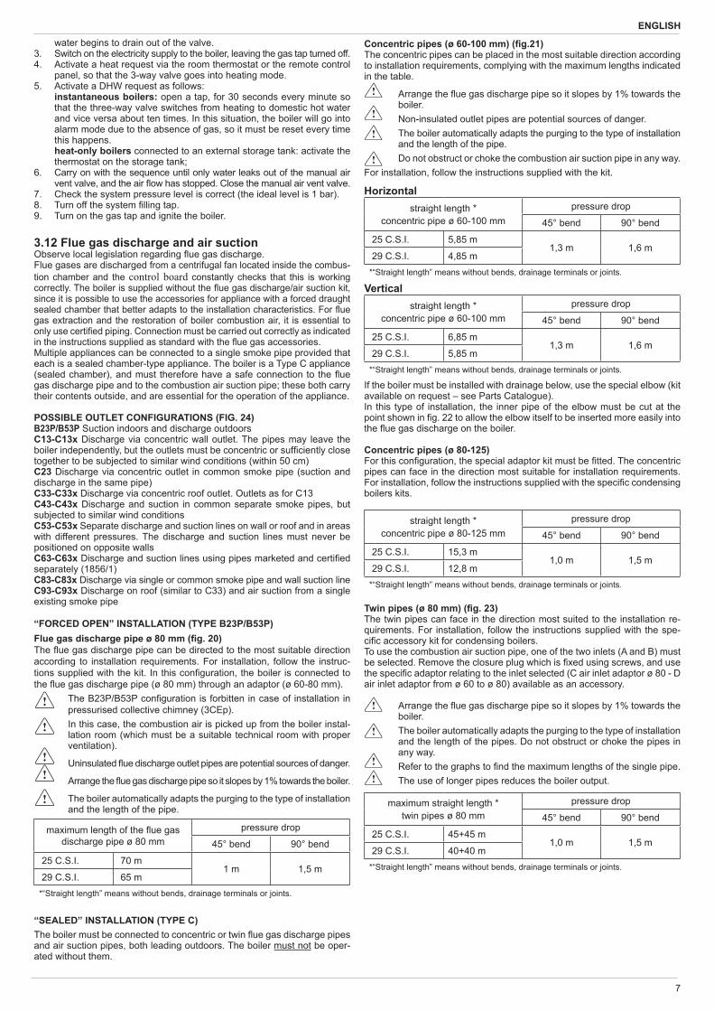
“FORCED OPEN” INSTALLATION (TYPE B23P/B53P)Flue gas discharge pipe ø 80 mm ( g. 20)The ue gas discharge pipe can be directed to the most suitable direction according to installation requirements. For installation, follow the instruc-tions supplied with the kit. In this con guration, the boiler is connected to the ue gas discharge pipe (ø 80 mm) through an adaptor (ø 60-80 mm).
The B23P/B53P con guration is forbitten in case of installation in pressurised collective chimney (3CEp).
In this case, the combustion air is picked up from the boiler instal-lation room (which must be a suitable technical room with proper ventilation).
Uninsulated ue discharge outlet pipes are potential sources of danger.
Arrange the ue gas discharge pipe so it slopes by 1% towards the boiler.
The boiler automatically adapts the purging to the type of installation and the length of the pipe.
maximum length of the ue gasdischarge pipe ø 80 mm
pressure drop
45° bend 90° bend
25 C.S.I. 70 m1 m 1,5 m
29 C.S.I. 65 m*“Straight length” means without bends, drainage terminals or joints.
“SEALED” INSTALLATION (TYPE C)The boiler must be connected to concentric or twin ue gas discharge pipes and air suction pipes, both leading outdoors. The boiler must not be oper-ated without them.
Concentric pipes (ø 60-100 mm) ( g.21)The concentric pipes can be placed in the most suitable direction according to installation requirements, complying with the maximum lengths indicated in the table.
Arrange the ue gas discharge pipe so it slopes by 1% towards the boiler.
Non-insulated outlet pipes are potential sources of danger. The boiler automatically adapts the purging to the type of installation
and the length of the pipe. Do not obstruct or choke the combustion air suction pipe in any way.
For installation, follow the instructions supplied with the kit.
Horizontalstraight length *
concentric pipe ø 60-100 mmpressure drop
45° bend 90° bend
25 C.S.I. 5,85 m1,3 m 1,6 m
29 C.S.I. 4,85 m*“Straight length” means without bends, drainage terminals or joints.
Verticalstraight length *
concentric pipe ø 60-100 mmpressure drop
45° bend 90° bend
25 C.S.I. 6,85 m1,3 m 1,6 m
29 C.S.I. 5,85 m*“Straight length” means without bends, drainage terminals or joints.
If the boiler must be installed with drainage below, use the special elbow (kit available on request – see Parts Catalogue).In this type of installation, the inner pipe of the elbow must be cut at the point shown in g. 22 to allow the elbow itself to be inserted more easily into the ue gas discharge on the boiler.
Concentric pipes (ø 80-125)For this con guration, the special adaptor kit must be tted. The concentric pipes can face in the direction most suitable for installation requirements. For installation, follow the instructions supplied with the speci c condensing boilers kits.
straight length *concentric pipe ø 80-125 mm
pressure drop
45° bend 90° bend
25 C.S.I. 15,3 m1,0 m 1,5 m
29 C.S.I. 12,8 m*“Straight length” means without bends, drainage terminals or joints.
Twin pipes (ø 80 mm) ( g. 23)The twin pipes can face in the direction most suited to the installation re-quirements. For installation, follow the instructions supplied with the spe-ci c accessory kit for condensing boilers.To use the combustion air suction pipe, one of the two inlets (A and B) must be selected. Remove the closure plug which is xed using screws, and use the speci c adaptor relating to the inlet selected (C air inlet adaptor ø 80 - D air inlet adaptor from ø 60 to ø 80) available as an accessory.
Arrange the ue gas discharge pipe so it slopes by 1% towards the boiler.
The boiler automatically adapts the purging to the type of installation and the length of the pipes. Do not obstruct or choke the pipes in any way.
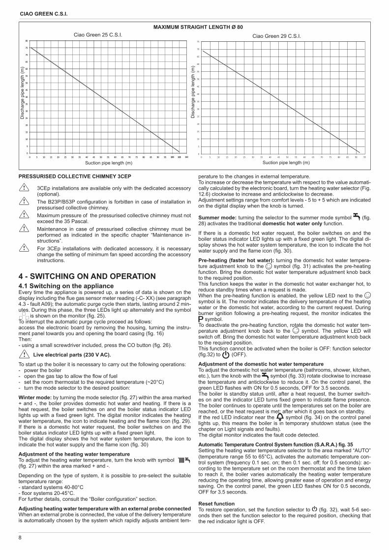
Refer to the graphs to nd the maximum lengths of the single pipe. The use of longer pipes reduces the boiler output.
maximum straight length *twin pipes ø 80 mm
pressure drop
45° bend 90° bend
25 C.S.I. 45+45 m1,0 m 1,5 m
29 C.S.I. 40+40 m*“Straight length” means without bends, drainage terminals or joints.
8
CIAO GREEN C.S.I.
Suction pipe length (m)
Dis
char
ge p
ipe
leng
th (m
)
80
0
5
10
15
20
25
30
35
40
45
50
55
60
65
70
75
0 5 10 15 20 25 30 35 40 45 50 55 60 65 70 75 80 85 90 95 100100 105105 1101100
5
10
15
20
25
30
35
40
45
50
55
60
65
70
75
0 5 10 15 20 25 30 35 40 45 50 55 60 65 70 75 80 85 90 95
MAXIMUM STRAIGHT LENGTH Ø 80Ciao Green 25 C.S.I. Ciao Green 29 C.S.I.
Dis
char
ge p
ipe
leng
th (m
)
Suction pipe length (m)
PRESSURISED COLLECTIVE CHIMNEY 3CEP
3CEp installations are available only with the dedicated accessory (optional).
The B23P/B53P con guration is forbitten in case of installation in pressurised collective chimney.
Maximum pressure of the pressurised collective chimney must not exceed the 35 Pascal.
Maintenance in case of pressurised collective chimney must be performed as indicated in the speci c chapter “Maintenance in-structions”.
For 3CEp installations with dedicated accessory, it is necessary change the setting of minimum fan speed according the accessory instructions.
4 - SWITCHING ON AND OPERATION4.1 Switching on the applianceEvery time the appliance is powered up, a series of data is shown on the display including the ue gas sensor meter reading (-C- XX) (see paragraph 4.3 - fault A09); the automatic purge cycle then starts, lasting around 2 min-utes. During this phase, the three LEDs light up alternately and the symbol
is shown on the monitor ( g. 25). To interrupt the automatic purge cycle proceed as follows:access the electronic board by removing the housing, turning the instru-ment panel towards you and opening the board casing ( g. 16)Then:- using a small screwdriver included, press the CO button ( g. 26).
Live electrical parts (230 V AC).
To start up the boiler it is necessary to carry out the following operations:- power the boiler- open the gas tap to allow the ow of fuel - set the room thermostat to the required temperature (~20°C)- turn the mode selector to the desired position:
Winter mode: by turning the mode selector ( g. 27) within the area marked + and -, the boiler provides domestic hot water and heating. If there is a heat request, the boiler switches on and the boiler status indicator LED lights up with a xed green light. The digital monitor indicates the heating water temperature, the icon to indicate heating and the ame icon ( g. 29).If there is a domestic hot water request, the boiler switches on and the boiler status indicator LED lights up with a xed green light.The digital display shows the hot water system temperature, the icon to indicate the hot water supply and the ame icon ( g. 30)
Adjustment of the heating water temperature To adjust the heating water temperature, turn the knob with symbol ( g. 27) within the area marked + and -.
Depending on the type of system, it is possible to pre-select the suitable temperature range:- standard systems 40-80°C- oor systems 20-45°C.For further details, consult the “Boiler con guration” section.
Adjusting heating water temperature with an external probe connectedWhen an external probe is connected, the value of the delivery temperature is automatically chosen by the system which rapidly adjusts ambient tem-
perature to the changes in external temperature.To increase or decrease the temperature with respect to the value automati-cally calculated by the electronic board, turn the heating water selector (Fig. 12.6) clockwise to increase and anticlockwise to decrease.Adjustment settings range from comfort levels - 5 to + 5 which are indicated on the digital display when the knob is turned.
Summer mode: turning the selector to the summer mode symbol ( g. 28) activates the traditional domestic hot water only function.
If there is a domestic hot water request, the boiler switches on and the boiler status indicator LED lights up with a xed green light. The digital di-splay shows the hot water system temperature, the icon to indicate the hot water supply and the ame icon ( g. 30).
Pre-heating (faster hot water): turning the domestic hot water tempera-ture adjustment knob to the symbol ( g. 31) activates the pre-heating function. Bring the domestic hot water temperature adjustment knob back to the required position.This function keeps the water in the domestic hot water exchanger hot, to reduce standby times when a request is made.When the pre-heating function is enabled, the yellow LED next to the symbol is lit. The monitor indicates the delivery temperature of the heating water or the domestic hot water, according to the current request. During burner ignition following a pre-heating request, the monitor indicates the
symbol.To deactivate the pre-heating function, rotate the domestic hot water tem-perature adjustment knob back to the symbol. The yellow LED will switch off. Bring the domestic hot water temperature adjustment knob back to the required position.This function cannot be activated when the boiler is OFF: function selector ( g.32) to (OFF).
Adjustment of the domestic hot water temperatureTo adjust the domestic hot water temperature (bathrooms, shower, kitchen, etc.), turn the knob with the symbol ( g. 33) rotate clockwise to increase the temperature and anticlockwise to reduce it. On the control panel, the green LED ashes with ON for 0.5 seconds, OFF for 3.5 seconds.The boiler is standby status until, after a heat request, the burner switch-es on and the indicator LED turns xed green to indicate ame presence. The boiler continues to operate until the temperatures set on the boiler are reached, or the heat request is met; after which it goes back on standby.If the red LED indicator near the symbol ( g. 34) on the control panel lights up, this means the boiler is in temporary shutdown status (see the chapter on Light signals and faults).The digital monitor indicates the fault code detected.
Automatic Temperature Control System function (S.A.R.A.) g. 35Setting the heating water temperature selector to the area marked “AUTO” (temperature range 55 to 65°C), activates the automatic temperature con-trol system (frequency 0.1 sec. on; then 0.1 sec. off; for 0.5 seconds): ac-cording to the temperature set on the room thermostat and the time taken to reach it, the boiler varies automatically the heating water temperature reducing the operating time, allowing greater ease of operation and energy saving. On the control panel, the green LED ashes ON for 0.5 seconds, OFF for 3.5 seconds.
Reset functionTo restore operation, set the function selector to ( g. 32), wait 5-6 sec-onds then set the function selector to the required position, checking that the red indicator light is OFF.
9
ENGLISH
At this point the boiler will automatically start and the red lamp switches on in green.N.B. If the attempt to reset the appliance does not activate operation, contact the Technical Assistance Service.
4.2 Switching offTemporary switch-offIn case of absence for short periods of time, set the mode selector ( g. 32) to (OFF).In this way (leaving the electricity and fuel supplies enabled), the boiler is protected by the following systems:Anti-frost device: when the temperature of the water in the boiler falls below 5°C, the circulator and, if necessary, the burner are activated at minimum output levels to bring the water temperature back to the values for safety (35°C). During the anti-frost cycle, the symbol ( g. 36) appears on the digital monitor.Circulator anti-blocking function: an operation cycle is activated every 24 hours.
Switching off for long periodsIn case of absence for long periods of time, set the mode selector ( g. 32) to (OFF). Turn the main system switch OFF. Close the fuel and water taps of the heating and domestic hot water system. In this case, anti-frost device is deactivated: drain the systems, in case of risk of frost.
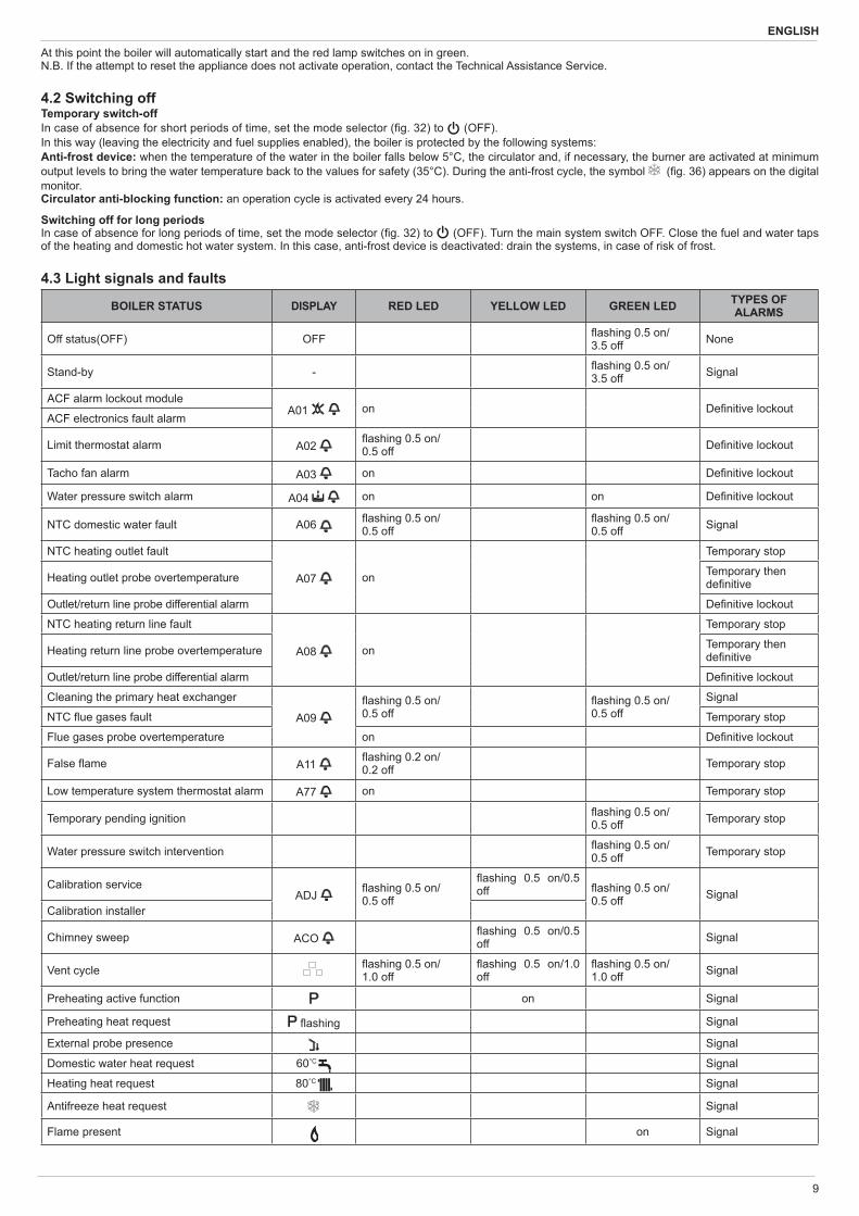
4.3 Light signals and faults
BOILER STATUS DISPLAY RED LED YELLOW LED GREEN LED TYPES OF ALARMS
Off status(OFF) OFF ashing 0.5 on/3.5 off None
Stand-by - ashing 0.5 on/3.5 off Signal
ACF alarm lockout moduleA01 on De nitive lockout
ACF electronics fault alarm
Limit thermostat alarm A02 ashing 0.5 on/0.5 off De nitive lockout
Tacho fan alarm A03 on De nitive lockout
Water pressure switch alarm A04 on on De nitive lockout
NTC domestic water fault A06 ashing 0.5 on/0.5 off
ashing 0.5 on/0.5 off Signal
NTC heating outlet fault
A07 on
Temporary stop
Heating outlet probe overtemperature Temporary then de nitive
Outlet/return line probe differential alarm De nitive lockout
NTC heating return line fault
A08 on
Temporary stop
Heating return line probe overtemperature Temporary then de nitive
Outlet/return line probe differential alarm De nitive lockout
Cleaning the primary heat exchanger
A09 ashing 0.5 on/0.5 off
ashing 0.5 on/0.5 off
Signal
NTC ue gases fault Temporary stop
Flue gases probe overtemperature on De nitive lockout
False ame A11 ashing 0.2 on/0.2 off Temporary stop
Low temperature system thermostat alarm A77 on Temporary stop
Temporary pending ignition ashing 0.5 on/0.5 off Temporary stop
Water pressure switch intervention ashing 0.5 on/0.5 off Temporary stop
Calibration serviceADJ ashing 0.5 on/
0.5 off
ashing 0.5 on/0.5 off ashing 0.5 on/
0.5 off SignalCalibration installer
Chimney sweep ACO ashing 0.5 on/0.5 off Signal
Vent cycle ashing 0.5 on/1.0 off
ashing 0.5 on/1.0 off
ashing 0.5 on/1.0 off Signal
Preheating active function on Signal
Preheating heat request ashing Signal
External probe presence Signal
Domestic water heat request 60°C Signal
Heating heat request 80°C Signal
Antifreeze heat request Signal
Flame present on Signal
10
CIAO GREEN C.S.I.
To restore operation (deactivate alarms):Faults A 01-02-03Position the function selector to (OFF), wait 5-6 seconds then set it to the required position (summer mode) or (winter mode).If the reset attempts do not reactivate the boiler, contact the Technical As-sistance Centre.Fault A 04In addition to the fault code, the digital display shows the symbol .Check the pressure value indicated by the water gauge: if it is less than 0.3 bar, position the function selector to (OFF) and adjust the lling tap until the pressure reaches a value between 1 and 1.5 bar. Then position the mode selector to the desired position (summer) or (winter). The boiler will perform one purge cycle lasting approximately 2 minutes. If pressure drops are frequent, request the intervention of the Technical As-sistance Service.Fault A 06The boiler operates normally but cannot reliably maintain a constant do-mestic hot water temperature, which remains set at around 50°C. Contact the Technical Assistance Centre.Fault A 07 - A 08Contact the Technical Assistance Centre.Fault A 09 with xed red LED litPosition the function selector to (OFF), wait 5-6 seconds then set it to the required position (summer mode) or (winter mode). If the reset attempts do not reactivate the boiler, request the intervention of the Technical As-sistance Service.Fault A 09 with ashing red and green LEDsThe boiler is equipped with an auto-diagnostic system which, based on the total number of hours in certain operating conditions, can signal the need to clean the primary exchanger (alarm code 09 with ashing red and green LEDs and ue gas meter >2,500). Once the cleaning operation has been completed, using the special kit supplied as an accessory, the total hour meter will need to be reset to zero as follows: - switch off the power supply- remove the housing - loosen the xing screw then turn the instrument panel- loosen the xing screws on the cover (F) to access the terminal board ( g. 16) - while the boiler is powered up, using a small screwdriver included, press
the CO button ( g. 26) for at least 4 seconds, to check the meter has been reset, power down then power up the boiler; the meter reading is shown on the monitor after the “-C-” sign.
Live electrical parts (230 V AC).
Note: the meter resetting procedure should be carried out after each in-depth cleaning of the primary exchanger or if this latter is replaced. To check the status of the total hour meter, multiply the reading by 100 (e.g. reading of 18 = 1800 total hours; reading of 1 = 100 total hours).The boiler continues to operate normally even when the alarm is activated.Fault A 77This is an automatic-reset fault, if the boiler does not restart, contact the Technical Assistance Centre.Fixed yellow LED Pre-heating function activated Flashing yellow LEDCombustion analysis in progress.
4.4 Alarm recordsThe “ALARM RECORDS” function starts automatically once the display has been on for 2 hours, or immediately by setting the P1 parameter to 1. The records include all the latest alarms, up to a maximum of 5 alarms, and they are displayed in sequence by pushing and releasing the P1 button on the display board. If the records are empty (P0=0) or if tracking the same is disabled (P1=0), the display function is not available. Alarms are displayed in reverse order compared to the order in which they occurred: this means that the last alarm generated is the rst to be displayed. To delete the alarms records, simply set parameter P0 to 0. NOTE: To get to the P1 button the cover on the control panel must be remo-ved and the display board must be identi ed ( g. 37a).
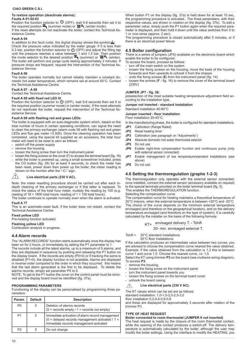
PROGRAMMING PARAMETERS Functioning of the display can be personalised by programming three pa-rameters:
Param. Default Description
P0 0 Deletion of alarms records (0 = records empty / 1 = records not empty)
P1 0 Immediate activation of alarm record management (0 = delayed records management activated / 1 = immediate records management activated
P2 0 Do not change
envisaged delivery T. - TshiftKT= 20- min. envisaged external T.
When button P1 on the display ( g. 37a) is held down for at least 10 sec, the programming procedure is activated. The three parameters, with their respective values, are shown in rotation on the display ( g. 37b). To edit a parameter value, simply push the P1 button again when the required para-meter is displayed, and then hold it down until the value switches from 0 to 1 or vice-versa (approx. 2 sec). The programming procedure is closed automatically after 5 minutes, or if there is an electrical power failure
4.5 Boiler con guration There is a series of jumpers (JPX) available on the electronic board which enable the boiler to be con gured.To access the board, proceed as follows:- turn off the main switch on the system- loosen the xing screws on the housing, move the base of the housing
forwards and then upwards to unhook it from the chassis- undo the xing screws (E) from the instrument panel ( g. 14) - loosen the screws (F - g. 16) to remove the cover of the terminal board
(230V)
JUMPER JP7 - g. 38: preselection of the most suitable heating temperature adjustment eld ac-cording to the installation type. Jumper not inserted - standard installationStandard installation 40-80°CJumper inserted - oor installationFloor installation 20-45°C.In the manufacturing phase, the boiler is con gured for standard installations.JP1 Calibration (Range Rated)JP2 Reset heating timerJP3 Calibration (see paragraph on “Adjustments”)JP4 Absolute domestic hot water thermostat selectorJP5 Do not use JP6 Enable night-time compensation function and continuous pump (only
with external sensor connected)JP7 Enable management of low temperature/standard installations (see
above) JP8 Do not use
4.6 Setting the thermoregulation (graphs 1-2-3)The thermoregulation only operates with the external sensor connected; once installed, connect the external sensor (accessory available on request) to the special terminals provided on the boiler terminal board ( g. 5).This enables the THERMOREGULATION function.Selecting the compensation curveThe compensation curve for heating maintains a theoretical temperature of 20°C indoors, when the external temperature is between +20°C and -20°C. The choice of the curve depends on the minimum external temperature envisaged (and therefore on the geographical location), and on the delivery temperature envisaged (and therefore on the type of system). It is carefully calculated by the installer on the basis of the following formula:
Tshift = 30°C standard installations 25°C oor installations If the calculation produces an intermediate value between two curves, you are advised to choose the compensation curve nearest the value obtained.Example: if the value obtained from the calculation is 1,3 this is between curve 1 and curve 1,5. Choose the nearest curve, i.e. 1,5.Select the KT using trimmer P3 on the board (see multiwire wiring diagram).To access P3:- remove the housing, - loosen the xing screw on the instrument panel- turn the instrument panel towards you- loosen the xing screws on the terminal board cover- unhook the board casing Live electrical parts (230 V AC).
The KT values which can be set are as follows:standard installation: 1,0-1,5-2,0-2,5-3,0 oor installation 0,2-0,4-0,6-0,8 and these are displayed for approximately 3 seconds after rotation of the trimmer P3.
TYPE OF HEAT REQUESTBoiler connected to room thermostat (JUMPER 6 not inserted)The heat request is made by the closure of the room thermostat contact, while the opening of the contact produces a switch-off. The delivery tem-perature is automatically calculated by the boiler, although the user may modify the boiler settings. Using the interface to modify the HEATING, you
11
ENGLISH
will not have the HEATING SET-POINT value available, but a value that you can set as preferred between 15 and 25°C. The modi cation of this value will not directly modify the delivery temperature, but will automatically affect the calculation that determines the value of that temperature, altering the reference temperature in the system (0 = 20°C).Boiler connected to a programmable timer (JUMPER JP6 inserted)With the contact closed, the heat request is made by the delivery sensor, on the basis of the external temperature, to obtain a nominal indoor tempera-ture on DAY level (20°C). With the contact open, the boiler is not switched off, but the weather curve is reduced (parallel shift) to NIGHT level (16°C). This activates the night-time function. The delivery temperature is automati-cally calculated by the boiler, although the user may modify the boiler set-tings. Using the interface to modify the HEATING, you will not have the HEATING SET-POINT value available, but a value that you can set as pre-ferred between 25 and 15°C. The modi cation of this value will not directly modify the delivery temperature, but will automatically affect the calculation that determines the value of that temperature, altering the reference tempera-ture in the system (0 = 20°C for DAY level, and 16°C for NIGHT level).
4.7 AdjustmentsThe boiler has already been adjusted by the manufacturer during produc-tion. If the adjustments need to be made again, for example after extraordi-nary maintenance, replacement of the gas valve, or conversion from meth-ane gas to LPG, observe the following procedures.The adjustment of the maximum and minimum output, and of the maximum and minimum heating and of slow switch-on, must be made strictly in the sequence indicated, and only by quali ed personnel only:- disconnect the boiler from the power supply- turn the heating water temperature selector to its maximum - loosen the xing screws (E) on the instrument panel ( g. 14)- lift then turn the instrument panel towards you - loosen the xing screws on the cover (F) to access the terminal board ( g. 16) - insert the jumpers JP1 and JP3 ( g. 40)- power up the boilerThe three LEDs on the instrument panel ash simultaneously and the dis-play shows “ADJ” for approximately 4 secondsNext change the following parameters:1 - Domestic hot water/absolute maximum2 - Minimum3 - Heating maximum4 - Slow switch-onas follows:- turn the heating water temperature selector to set the required value - press the CO button using a small screwdriver included ( g. 26) and then
skip to the calibration of the next parameter.
Live electrical parts (230 V AC).
The following icons light up on the monitor:1. during domestic hot water/absolute maximum calibration 2. during minimum calibration3. during heating maximum calibration4. during slow switch-on calibration
End the procedure by removing jumpers JP1 and JP3 to store these set val-ues in the memory. The function can be ended at any time without storing the set values in the memory and retaining the original values as follows:- remove jumpers JP1 and JP3 before all 4 parameters have been set- set the function selector to (OFF/RESET) - cut the power supply 15 minutes after it is connected.
Calibration can be carried out without powering up the boiler. By turning the heating selection knob, the monitor automatically
shows the number of rotations, expressed in hundreds (e.g. 25 = 2,500 rpm).
For 3CEp installations with dedicated accessory, it is necessary change the setting of minimum fan speed according the accessory instructions.
The function for visualizing the setting parameters is activated by the func-tion selector in summer and in winter, by pressing the CO button on the circuit board, either with or without request for heat. This function cannot be activated when connected to a remote control. Upon activating the function the setting parameters are visualized in the order given below, each for 2 seconds. Each parameter is displayed together with its corresponding icon and fan rotation speed measured in hundreds
1. Maximum
2. Minimum
3. Max. heating
4. Slow ignition P5. Max. preset heating
GAS VALVE CALIBRATION- Connect the boiler to the power supply- Open the gas tap- Set the function selector to (OFF/RESET) (monitor off)- Loosen the screws (E), remove the housing, then lower the instrument
panel towards you ( g. 14)- Loosen the xing screws on the cover (F) to access the terminal board
( g. 16) - Using a small screwdriver included, press the CO button ( g. 26)
Live electrical parts (230 V AC).
- Wait for burner ignition. The display shows “ACO” and the yellow LED ashes. The boiler oper-
ates at maximum heat output. The “combustion analysis” function remains active for a limited time (15
min); if a delivery temperature of 90°C is reached, the burner is switched off. It will be switched back on when this temperature drops below 78°C.
- Insert the analyser probe in the ports provided in the air distribution box, after removing the screws from the cover ( g. 41)
- Press the “combustion analysis” button a second time to reach the num-ber of rotations corresponding to the maximum domestic hot water output (table 1); the yellow LED continues to ash while the red LED is xed
- Check the CO2 value: (table 3) if the value does not match the value given in the table, use the gas valve maximum adjustment screw
- Press the “combustion analysis” button a third time to reach the number of rotations corresponding to the minimum output (table 2); the yellow LED continues to ash while the green LED is xed
- Check the CO2 value: (table 4) if the value does not match the value given in the table, use the gas valve minimum adjustment screw
- To exit the “combustion analysis” function, turn the control knob- Remove the ue gas probe and re t the plug- Close the instrument panel and re t the housing.
The “combustion analysis” function is automatically deactivated if the board triggers an alarm. In the event of a fault during the combustion analysis cycle, carry out the reset procedure.
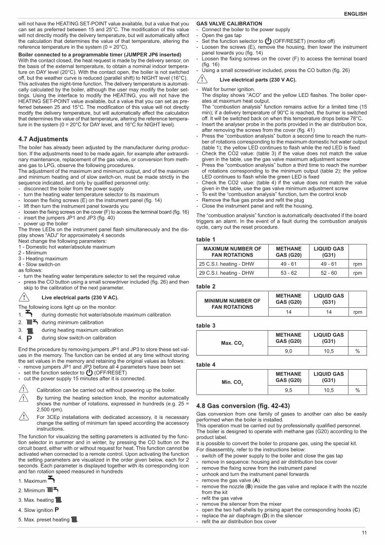
table 1MAXIMUM NUMBER OF
FAN ROTATIONSMETHANE GAS (G20)
LIQUID GAS (G31)
25 C.S.I. heating - DHW 49 - 61 49 - 61 rpm
29 C.S.I. heating - DHW 53 - 62 52 - 60 rpm
table 2
MINIMUM NUMBER OF FAN ROTATIONS
METHANE GAS (G20)
LIQUID GAS (G31)
14 14 rpm
table 3
Max. CO2
METHANE GAS (G20)
LIQUID GAS (G31)
9,0 10,5 %
table 4
Min. CO2
METHANE GAS (G20)
LIQUID GAS (G31)
9,5 10,5 %
4.8 Gas conversion ( g. 42-43)Gas conversion from one family of gases to another can also be easily performed when the boiler is installed.This operation must be carried out by professionally quali ed personnel.The boiler is designed to operate with methane gas (G20) according to the product label.It is possible to convert the boiler to propane gas, using the special kit.For disassembly, refer to the instructions below:- switch off the power supply to the boiler and close the gas tap- remove in sequence: housing and air distribution box cover- remove the xing screw from the instrument panel- unhook and turn the instrument panel forwards- remove the gas valve (A)- remove the nozzle (B) inside the gas valve and replace it with the nozzle
from the kit- re t the gas valve- remove the silencer from the mixer- open the two half-shells by prising apart the corresponding hooks (C)- replace the air diaphragm (D) in the silencer - re t the air distribution box cover
12
CIAO GREEN C.S.I.
- re-power the boiler and turn on the gas tapAdjust the boiler as described in the chapter entitled “Adjustments” with reference to the information on LPG.
Conversion must be carried out by quali ed personnel. Once the conversion is complete, af x the new identi cation
label supplied in the kit.
4.9 Checking the combustion parametersTo carry out the combustion analysis, proceed as follows: - set the main switch of the installation to the “OFF” position - loosen the xing screws (D) on the housing ( g. 13) - move the base of the housing forwards and then upwards to unhook it
from the chassis - loosen the xing screws (E) on the instrument panel ( g. 14) - lift then turn the instrument panel towards you - loosen the xing screws on the cover (F) to access the terminal board ( g. 16) - using a small screwdriver included, press the CO button ( g. 26)
Live electrical parts (230 V AC).
- Wait for burner ignition. The display shows “ACO”, the yellow LED ash-es and the boiler operates at maximum heat output.
- insert the analyser probe in the ports provided in the air distribution box, after removing the screws from the cover ( g. 41)
- check that the CO2 values match those given in the table, if the value shown is different, change it as indicated in the chapter entitled “Gas valve calibration”.
- perform the combustion check.
Then: - remove the analyser probe and close the sockets for combustion analy-
sis with the special screw - close the instrument panel and re t the housing
The ue gas analysis probe must be fully inserted as far as pos-sible.
IMPORTANTEven during the combustion analysis phase, the function that switches the boiler off when the water temperature reaches the maximum limit (about 90°C) remains enabled.
5 MAINTENANCEThe appliance must be systematically controlled at regular intervals to make sure it works correctly and ef ciently and conforms to legislative pro-visions in force.The frequency of controls depends on the conditions of installation and usage, it being anyhow necessary to have a complete check carried out by authorized personnel from the Servicing Centre every year.- Check and compare the boiler’s performance with the relative speci ca-
tions. Any cause of visible deterioration must be immediately identi ed and eliminated.
- Closely inspect the boiler for signs of damages or deterioration, particu-larly with the drainage and aspiration system and electrical apparatus.
- Check and adjust – where necessary – all the burner’s parameters.- Check and adjust – where necessary – the system’s pressure.- Analyze combustion. Compare results with the product’s speci cation. Any loss in performance must be identi ed and corrected by nding and
eliminating the cause.- Make sure the main heat exchanger is clean and free of any residuals or
obstruction.- Check and clean – where necessary – the condensation tray to make
sure it works properly.
IMPORTANT: always switch off the power to the appliance and close the gas by the gas cock on the boiler before carrying out any maintenance and cleaning jobs on the boiler.Do not clean the appliance or any latter part with ammable substances (e.g. petrol, alcohol, etc.).Do not clean panelling, enamelled and plastic parts with paint solvents.Panels must be cleaned with ordinary soap and water only.
The ame side of the burner is made of state-of-the-art material.Being fragile:- be particularly careful when handling, mounting or dismantling the burner
and adjacent components (e.g. electrodes, insulation panelling etc.)- avoid direct contact with any cleaning appliance (e.g. brushes, aspira-
tors, blowers, etc.).
This component does not need any maintenance, please do not remove it from its housing, save where the O-ring may have to be replaced.The manufacturer declines all responsibility in cases of damages due to failing to observe the above.
MAINTENANCE FOR PRESSURISED COLLECTIVE CHIMNEY (3CEP)In the event of maintenance operations on the boiler which require the ue gas pipes to be disconnected, a cap should be placed on the open element originating from the pressurised smoke pipe.Failure to adhere to the guidelines provided can compromise the security of persons and animals due to potential leakages of carbon monoxide from the smoke pipe.
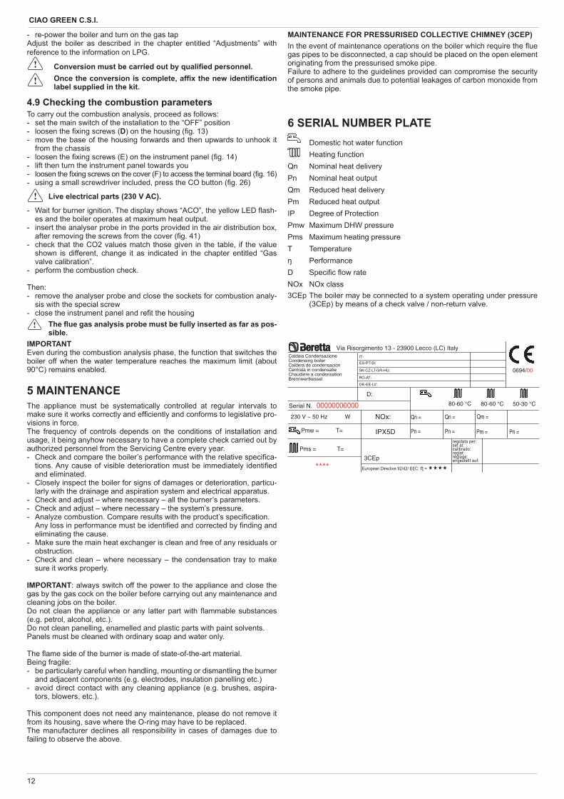
6 SERIAL NUMBER PLATE Domestic hot water function
Heating functionQn Nominal heat deliveryPn Nominal heat outputQm Reduced heat deliveryPm Reduced heat outputIP Degree of ProtectionPmw Maximum DHW pressurePms Maximum heating pressureT Temperature
PerformanceD Speci c ow rateNOx NOx class3CEp The boiler may be connected to a system operating under pressure
(3CEp) by means of a check valve / non-return valve.
0694/00
Serial N. 00000000000230 V ~ 50 Hz W
****
NOx:
Pms = T=
η
Caldaia CondensazioneCondensing boilerCaldera de condensaciónCentrala in condensatieChaudiere a condensationBrennwertkessel
regolata per:set at:calibrado:reglat:réglage:engestellt auf:
Via Risorgimento 13 - 23900 Lecco (LC) Italy
SK-CZ-LT-GR-HU:
IPX5D
RO-AT:
Pmw = T=
D:
80-60 °C 80-60 °C 50-30 °C
Qn =
Pn =
Qn =
Pn =
Qm =
Pm = Pn =
DK-EE-LV:
ES-PT-SI:
IT:
3CEp
13
ENGLISH
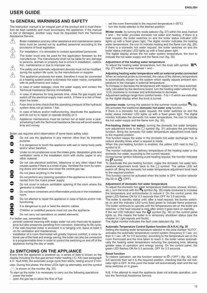
USER GUIDE 1a GENERAL WARNINGS AND SAFETY The instruction manual is an integral part of the product and it must there-fore be kept carefully and must accompany the appliance; if the manual is lost or damaged, another copy must be requested from the Technical Assistance Service.
Boiler installation and any other assistance and maintenance opera-tions must be carried out by quali ed personnel according to the provisions of local legislation.
For installation, it is advisable to contact specialised personnel. The boiler must only be used for the application foreseen by the
manufacturer. The manufacturer shall not be liable for any damage to persons, animals or property due to errors in installation, calibra-tion, maintenance or due to improper use.
The safety and automatic adjustment devices must not be modi ed, during the system life cycle, by the manufacturer or supplier.
This appliance produces hot water, therefore it must be connected to a heating system and/or a domestic hot water mains, compatible with its performance and output.
In case of water leakage, close the water supply and contact the Technical Assistance Service immediately.
In case of absence for long periods time, close the gas supply and switch off the electrical supply main switch. If there is a risk of frost, drain the boiler.
From time to time check that the operating pressure of the hydraulic system does not go below 1 bar.
In case of failure and/or malfunctioning, deactivate the appliance, and do not try to repair or operate directly on it.
Appliance maintenance must be carried out at least once a year: scheduling it with the Technical Assistance Service will avoid wasting time and money.
Boiler use requires strict observation of some basic safety rules: Do not use the appliance in any manner other than its intended
purpose. It is dangerous to touch the appliance with wet or damp body parts
and/or when barefoot. Under no circumstances cover the intake grids, dissipation grids and
ventilation vents in the installation room with cloths, paper or any other material.
Do not use electrical switches, telephone or any other object that causes sparks if there is a smell of gas. Ventilate the room by open-ing doors and windows and close the central gas tap.
Do not place anything in the boiler. Do not perform any cleaning operation if the appliance is not discon-
nected from the mains power supply. Do not cover or reduce ventilation opening of the room where the
generator is installed. Do not leave containers and in ammable products in the installation
room. Do not attempt to repair the appliance in case of failure and/or mal-
functioning. It is dangerous to pull or twist the electric cables. Children or unskilled persons must not use the appliance. Do not carry out operations on sealed elements.
For better use, remember that:- periodic external cleaning with soapy water not only improves its appear-
ance but also preserves panelling from corrosion, extending its life cycle;- if the wall-mounted boiler is enclosed in a hanging unit, leave at least 5
cm for ventilation and maintenance;- installation of a room thermostat will greatly improve comfort, a more ra-
tional use of the heat and energy saving; the boiler can also be connected to a programmable timer in order to control the switching on and off of the appliance during the day or week.
2a SWITCHING ON THE APPLIANCEEvery time the appliance is powered up, a series of data is shown on the display including the ue gas sensor meter reading (-C- XX) (see paragraph 4.3 - fault A09); the automatic purge cycle then starts, lasting around 2 min-utes. During this phase, the three LEDs light up alternately and the symbol
is shown on the monitor ( g. 25). To start up the boiler it is necessary to carry out the following operations:- power the boiler- open the gas tap to allow the ow of fuel
- set the room thermostat to the required temperature (~20°C)- turn the mode selector to the desired position:
Winter mode: by turning the mode selector ( g. 27) within the area marked + and -, the boiler provides domestic hot water and heating. If there is a heat request, the boiler switches on and the boiler status indicator LED lights up with a xed green light. The digital monitor indicates the heating water temperature, the icon to indicate heating and the ame icon ( g. 29).If there is a domestic hot water request, the boiler switches on and the boiler status indicator LED lights up with a xed green light.The digital display shows the hot water system temperature, the icon to indicate the hot water supply and the ame icon ( g. 30).
Adjustment of the heating water temperature To adjust the heating water temperature, turn the knob with symbol ( g. 27) within the area marked + and -.
Adjusting heating water temperature with an external probe connectedWhen an external probe is connected, the value of the delivery temperature is automatically chosen by the system which rapidly adjusts ambient tem-perature to the changes in external temperature.To increase or decrease the temperature with respect to the value automati-cally calculated by the electronic board, turn the heating water selector (Fig. 12.6) clockwise to increase and anticlockwise to decrease.Adjustment settings range from comfort levels - 5 to + 5 which are indicated on the digital display when the knob is turned.
Summer mode: turning the selector to the summer mode symbol ( g. 28) activates the traditional domestic hot water only function. If there is a domestic hot water request, the boiler switches on and the boiler status indicator LED lights up with a xed green light. The digital monitor indicates the domestic hot water temperature, the icon to indicate the hot water supply and the ame icon ( g. 30).
Pre-heating (faster hot water): turning the domestic hot water tempera-ture adjustment knob to the symbol ( g. 31) activates the pre-heating function. Bring the domestic hot water temperature adjustment knob back to the required position.This function keeps the water in the domestic hot water exchanger hot, to reduce standby times when a request is made.When the pre-heating function is enabled, the yellow LED next to the symbol is lit.The monitor indicates the delivery temperature of the heating water or the domestic hot water, according to the current request.During burner ignition following a pre-heating request, the monitor indicates the symbol.To deactivate the pre-heating function, rotate the domestic hot water tem-perature adjustment knob back to the symbol. The yellow LED will switch off. Bring the domestic hot water temperature adjustment knob back to the required position.This function cannot be activated when the boiler is OFF: function selector ( g.32) to (OFF).
Adjustment of domestic hot water temperatureTo adjust the domestic hot water temperature (bathrooms, shower, kitchen, etc.), turn the knob with the symbol ( g. 28) rotate clockwise to increase the temperature and anticlockwise to reduce it. On the control panel, the green LED ashes ON for 0.5 seconds then OFF for 3.5 seconds.The boiler is standby status until, after a heat request, the burner switch-es on and the indicator LED turns xed green to indicate ame presence. The boiler continues to operate until the temperatures set on the boiler are reached, or the heat request is met; after which it goes back on standby.If the red LED indicator near the symbol ( g. 34) on the control panel lights up, this means the boiler is in temporary shutdown status (see the chapter on Light signals and faults).The digital monitor indicates the fault code detected ( g. 34).
Automatic Temperature Control System function (S.A.R.A.) g. 35Setting the heating water temperature selector to the area marked “AUTO”, activates the automatic temperature control system (frequency 0.1 sec. on; then 0.1 sec. off; for 0.5 seconds): according to the temperature set on the room thermostat and the time taken to reach it, the boiler varies automati-cally the heating water temperature reducing the operating time, allowing greater ease of operation and energy saving. On the control panel, the green LED ashes ON for 0.5 seconds, OFF for 3.5 seconds.
Reset functionTo restore operation, set the function selector to (“OFF”) ( g. 32), wait 5-6 seconds then set it to the required position, checking that the red indi-cator light is OFF. At this point the boiler will automatically start and the red lamp switches on in green.
N.B. If the attempt to reset the appliance does not activate operation, con-tact the Technical Assistance Service.
14
CIAO GREEN C.S.I.
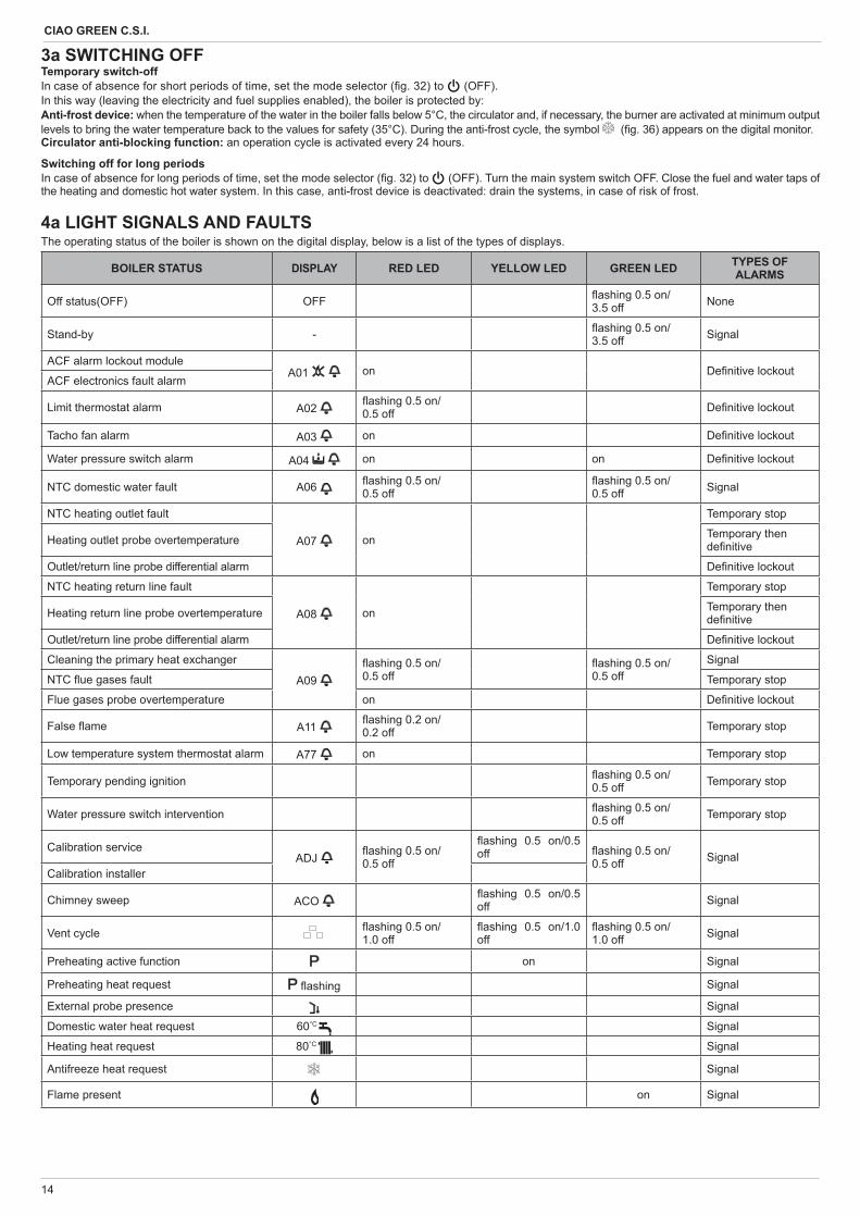
3a SWITCHING OFFTemporary switch-offIn case of absence for short periods of time, set the mode selector ( g. 32) to (OFF).In this way (leaving the electricity and fuel supplies enabled), the boiler is protected by:Anti-frost device: when the temperature of the water in the boiler falls below 5°C, the circulator and, if necessary, the burner are activated at minimum output levels to bring the water temperature back to the values for safety (35°C). During the anti-frost cycle, the symbol ( g. 36) appears on the digital monitor.Circulator anti-blocking function: an operation cycle is activated every 24 hours.
Switching off for long periodsIn case of absence for long periods of time, set the mode selector ( g. 32) to (OFF). Turn the main system switch OFF. Close the fuel and water taps of the heating and domestic hot water system. In this case, anti-frost device is deactivated: drain the systems, in case of risk of frost.
4a LIGHT SIGNALS AND FAULTSThe operating status of the boiler is shown on the digital display, below is a list of the types of displays.
BOILER STATUS DISPLAY RED LED YELLOW LED GREEN LED TYPES OF ALARMS
Off status(OFF) OFF ashing 0.5 on/3.5 off None
Stand-by - ashing 0.5 on/3.5 off Signal
ACF alarm lockout moduleA01 on De nitive lockout
ACF electronics fault alarm
Limit thermostat alarm A02 ashing 0.5 on/0.5 off De nitive lockout
Tacho fan alarm A03 on De nitive lockout
Water pressure switch alarm A04 on on De nitive lockout
NTC domestic water fault A06 ashing 0.5 on/0.5 off
ashing 0.5 on/0.5 off Signal
NTC heating outlet fault
A07 on
Temporary stop
Heating outlet probe overtemperature Temporary then de nitive
Outlet/return line probe differential alarm De nitive lockout
NTC heating return line fault
A08 on
Temporary stop
Heating return line probe overtemperature Temporary then de nitive
Outlet/return line probe differential alarm De nitive lockout
Cleaning the primary heat exchanger
A09 ashing 0.5 on/0.5 off
ashing 0.5 on/0.5 off
Signal
NTC ue gases fault Temporary stop
Flue gases probe overtemperature on De nitive lockout
False ame A11 ashing 0.2 on/0.2 off Temporary stop
Low temperature system thermostat alarm A77 on Temporary stop
Temporary pending ignition ashing 0.5 on/0.5 off Temporary stop
Water pressure switch intervention ashing 0.5 on/0.5 off Temporary stop
Calibration serviceADJ ashing 0.5 on/
0.5 off
ashing 0.5 on/0.5 off ashing 0.5 on/
0.5 off SignalCalibration installer
Chimney sweep ACO ashing 0.5 on/0.5 off Signal
Vent cycle ashing 0.5 on/1.0 off
ashing 0.5 on/1.0 off
ashing 0.5 on/1.0 off Signal
Preheating active function on Signal
Preheating heat request ashing Signal
External probe presence Signal
Domestic water heat request 60°C Signal
Heating heat request 80°C Signal
Antifreeze heat request Signal
Flame present on Signal
15
ENGLISH
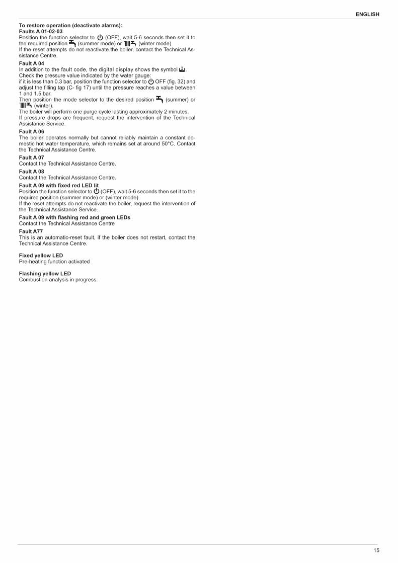
To restore operation (deactivate alarms):Faults A 01-02-03Position the function selector to (OFF), wait 5-6 seconds then set it to the required position (summer mode) or (winter mode).If the reset attempts do not reactivate the boiler, contact the Technical As-sistance Centre.Fault A 04In addition to the fault code, the digital display shows the symbol .Check the pressure value indicated by the water gauge:if it is less than 0.3 bar, position the function selector to OFF ( g. 32) and adjust the lling tap (C- g 17) until the pressure reaches a value between 1 and 1.5 bar.Then position the mode selector to the desired position (summer) or
(winter).The boiler will perform one purge cycle lasting approximately 2 minutes. If pressure drops are frequent, request the intervention of the Technical Assistance Service.Fault A 06The boiler operates normally but cannot reliably maintain a constant do-mestic hot water temperature, which remains set at around 50°C. Contact the Technical Assistance Centre.Fault A 07Contact the Technical Assistance Centre.Fault A 08Contact the Technical Assistance Centre.Fault A 09 with xed red LED litPosition the function selector to (OFF), wait 5-6 seconds then set it to the required position (summer mode) or (winter mode).If the reset attempts do not reactivate the boiler, request the intervention of the Technical Assistance Service.Fault A 09 with ashing red and green LEDsContact the Technical Assistance CentreFault A77This is an automatic-reset fault, if the boiler does not restart, contact the Technical Assistance Centre.
Fixed yellow LEDPre-heating function activated
Flashing yellow LEDCombustion analysis in progress.
16
CIAO GREEN C.S.I.
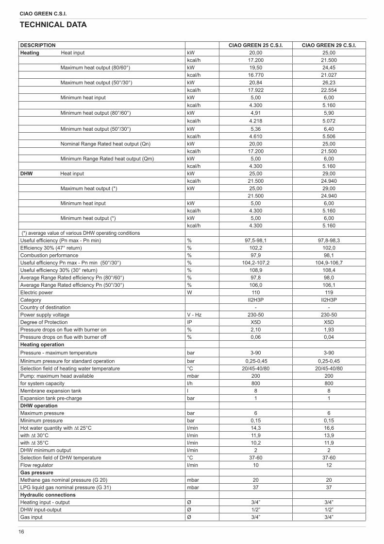
DESCRIPTION CIAO GREEN 25 C.S.I. CIAO GREEN 29 C.S.I.Heating Heat input kW 20,00 25,00
kcal/h 17.200 21.500Maximum heat output (80/60°) kW 19,50 24,45
kcal/h 16.770 21.027Maximum heat output (50°/30°) kW 20,84 26,23
kcal/h 17.922 22.554Minimum heat input kW 5,00 6,00
kcal/h 4.300 5.160Minimum heat output (80°/60°) kW 4,91 5,90
kcal/h 4.218 5.072Minimum heat output (50°/30°) kW 5,36 6,40
kcal/h 4.610 5.506Nominal Range Rated heat output (Qn) kW 20,00 25,00
kcal/h 17.200 21.500Minimum Range Rated heat output (Qm) kW 5,00 6,00
kcal/h 4.300 5.160DHW Heat input kW 25,00 29,00
kcal/h 21.500 24.940Maximum heat output (*) kW 25,00 29,00
21.500 24.940Minimum heat input kW 5,00 6,00
kcal/h 4.300 5.160Minimum heat output (*) kW 5,00 6,00
kcal/h 4.300 5.160 (*) average value of various DHW operating conditionsUseful ef ciency (Pn max - Pn min) % 97,5-98,1 97,8-98,3Ef ciency 30% (47° return) % 102,2 102,0Combustion performance % 97,9 98,1Useful ef ciency Pn max - Pn min (50°/30°) % 104,2-107,2 104,9-106,7Useful ef ciency 30% (30° return) % 108,9 108,4Average Range Rated ef ciency Pn (80°/60°) % 97,8 98,0Average Range Rated ef ciency Pn (50°/30°) % 106,0 106,1Electric power W 110 119Category II2H3P II2H3PCountry of destination - -Power supply voltage V - Hz 230-50 230-50Degree of Protection IP X5D X5DPressure drops on ue with burner on % 2,10 1,93 Pressure drops on ue with burner off % 0,06 0,04Heating operationPressure - maximum temperature bar 3-90 3-90Minimum pressure for standard operation bar 0,25-0,45 0,25-0,45Selection eld of heating water temperature °C 20/45-40/80 20/45-40/80 Pump: maximum head available mbar 200 200for system capacity l/h 800 800Membrane expansion tank l 8 8Expansion tank pre-charge bar 1 1DHW operationMaximum pressure bar 6 6Minimum pressure bar 0,15 0,15Hot water quantity with t 25°C l/min 14,3 16,6with t 30°C l/min 11,9 13,9with t 35°C l/min 10,2 11,9DHW minimum output l/min 2 2Selection eld of DHW temperature °C 37-60 37-60Flow regulator l/min 10 12Gas pressureMethane gas nominal pressure (G 20) mbar 20 20LPG liquid gas nominal pressure (G 31) mbar 37 37Hydraulic connectionsHeating input - output Ø 3/4” 3/4”DHW input-output Ø 1/2” 1/2”Gas input Ø 3/4” 3/4”
TECHNICAL DATA
17
ENGLISH
Multigas table
DESCRIPTION CIAO GREEN 25 C.S.I. CIAO GREEN 29 C.S.I.
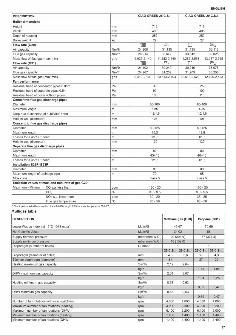
Boiler dimensionsHeight mm 715 715Width mm 405 405Depth of housing mm 250 250Boiler weight kg 27 27Flow rate (G20)Air capacity Nm3/h 24,908 31,135 31,135 36,116Flue gas capacity Nm3/h 26,914 33,642 33,642 39,025Mass ow of ue gas (max-min) gr/s 9,025-2,140 11,282-2,140 11,282-2,568 13,087-2,568Flow rate (G31)Air capacity Nm3/h 24,192 30,240 30,240 35,078Flue gas capacity Nm3/h 24,267 31,209 31,209 36,203Mass ow of ue gas (max-min) gr/s 8,410-2,103 10,513-2,103 10,513-2,523 12,195-2,523Fan performanceResidual head of concentric pipes 0.85m Pa 30 25Residual head of separate pipes 0.5m Pa 90 100Residual head of boiler without pipes Pa 100 110Concentric ue gas discharge pipesDiameter mm 60-100 60-100Maximum length m 5,85 4,85Drop due to insertion of a 45°/90° bend m 1,3/1,6 1,3/1,6Hole in wall (diameter) mm 105 105Concentric ue gas discharge pipesDiameter mm 80-125 80-125Maximum length m 15,3 12,8Losses for a 45°/90° bend m 1/1,5 1/1,5Hole in wall (diameter) mm 130 130Separate ue gas discharge pipesDiameter mm 80 80Maximum length m 45+45 40+40Losses for a 45°/90° bend m 1/1,5 1/1,5Installation B23P–B53PDiameter mm 80 80Maximum length of drainage pipe m 70 65NOx class class 5 class 5Emission values at max. and min. rate of gas G20*Maximum - Minimum CO s.a. less than ppm 180 - 20 160 - 20 CO2 % 9,0 - 9,5 9,0 - 9,5 NOx s.a. lower than ppm 30 - 20 35 - 25 Flue gas temperature °C 65 - 58 63 - 58
* Check performed with concentric pipe ø 60-100, length 0.85m - water temperature 80-60°C
DESCRIPTION Methane gas (G20) Propane (G31)
Lower Wobbe index (at 15°C-1013 mbar) MJ/m3S 45,67 70,69Net Calori c Value MJ/m3S 34,02 88Supply nominal pressure mbar (mm W.C.) 20 (203,9) 37 (377,3)Supply minimum pressure mbar (mm W.C.) 10 (102,0)Diaphragm (number of holes) Number 1 1
25 C.S.I. 29 C.S.I. 25 C.S.I. 29 C.S.I.Diaphragm (diameter of holes) mm 4,8 5,6 3,8 4,3Silencer diaphragm (diameter) mm 31 - 27 29Heating maximum gas capacity Sm3/h 2,12 2,64
kg/h 1,55 1,94DHW maximum gas capacity Sm3/h 2,64 3,07
kg/h 1,94 2,25Heating minimum gas capacity Sm3/h 0,53 0,63
kg/h 0,39 0,47DHW minimum gas capacity Sm3/h 0,53 0,63
kg/h 0,39 0,47Number of fan rotations with slow switch-on rpm 4.000 4.000 4.000 4.000Maximum number of fan rotations (heating) rpm 4.900 5.300 4.900 5.200Maximum number of fan rotations (DHW) rpm 6.100 6.200 6.100 6.000Minimum number of fan rotations (heating) rpm 1.400 1.400 1.400 1.400Minimum number of fan rotations (DHW) rpm 1.400 1.400 1.400 1.400
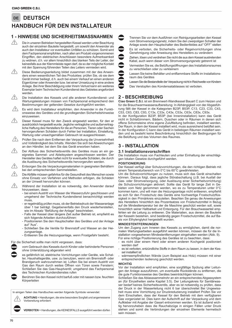
CIAO GREEN C.S.I.
70
CIAO GREEN C.S.I.
70
HANDBUCH FÜR DEN INSTALLATEURDE DEUTSCH
1 - HINWEISE UND SICHERHEITSMASSNAHMEN Die in unseren Betrieben hergestellten Kessel werden unter Beachtung
auch der einzelnen Bauteile hergestellt, um sowohl den Anwender als auch den Installateur vor eventuellen Unfällen zu schützen. Somit wird dem Fachpersonal empfohlen, nach allen am Produkt vorgenommenen Eingriffen, den elektrischen Anschlüssen besondere Aufmerksamkeit zu widmen, d.h. vor allem hinsichtlich des blanken Teils der Leiter, der keinesfalls aus der Klemmleiste ragen darf, da so der mögliche Kontakt mit den Spannung führenden Teilen des Leiters vermieden wird.
Diese Bedienungsanleitung bildet zusammen mit der des Anwen-ders einen wesentlichen Teil des Produktes: prüfen Sie, ob sie dem Gerät immer beiliegt, d.h. auch bei einem Verkauf an einen anderen Eigentümer oder Anwender bzw. bei einer Umsetzung in eine andere Anlage. Bei ihrer Beschädigung oder ihrem Verlust kann ein weiteres Exemplar beim Technischen Kundendienst des Gebietes angefordert werden.
Die Installation des Kessels und alle anderen Kundendienst- und Wartungsleistungen müssen von Fachpersonal entsprechend den Bestimmungen der geltenden Gesetze durchgeführt werden.
Es wird dem Installateur empfohlen, den Anwender in die Funkti-onsweise des Gerätes und die grundlegenden Sicherheitshinweise einzuweisen.
Dieser Kessel muss für den Zweck eingesetzt werden, für den er ausdrücklich hergestellt wurde. Jegliche vertragliche und außervertrag-liche Haftung des Herstellers für die an Personen, Tieren oder Sachen hervorgerufenen Schäden durch Fehler bei Installation, Einstellung, Wartung oder unsachgemäßen Gebrauch ist ausgeschlossen.
Prüfen Sie nach dem Entfernen der Verpackung die Unversehrtheit und Vollständigkeit des Inhalts. Wenden Sie sich bei Abweichungen an den Händler, bei dem Sie das Gerät erworben haben.
Der Ab uss des Sicherheitsventils des Gerätes muss an ein ge-eignetes Sammel- und Ableitsystem angeschlossen werden. Der Hersteller des Gerätes haftet nicht für eventuelle Schäden, die durch die Auslösung des Sicherheitsventils hervorgerufen werden.
Entsorgen Sie die Verpackungsmaterialien in geeigneten Behältern bei den entsprechenden Sammelstellen.
Die Abfälle müssen gefahrlos für die Gesundheit des Menschen sowie ohne Einsatz von Verfahren und Methoden erfolgen, die Schäden an der Umwelt hervorrufen können.
Während der Installation ist es notwendig, den Anwender darauf hinzuweisen, dass:
- bei einem Austritt von Wasser die Wasserzufuhr geschlossen und umgehend der Technische Kundendienst benachrichtigt werden muss,
- er regelmäßig prüfen muss, ob der Betriebsdruck der Wasseranlage über 1 bar beträgt. Gegebenenfalls den Druck wiederherstellen, wie im Absatz “Befüllung der Anlage” beschrieben.
- Falls der Kessel über längere Zeit außer Betrieb ist, emp ehlt es sich folgende Arbeiten durchzuführen:
- Positionieren Sie den Hauptschalter des Gerätes und der Anlage auf “Aus”.
- Schließen Sie die Ventile für Brennstoff und Wasser an der Hei-zungsanlage.
- Entleeren Sie die Heizungsanlage, wenn Frostgefahr besteht.
Für die Sicherheit sollte man nicht vergessen, dass: vom Gebrauch des Kessels durch Kinder oder behinderte Personen
ohne Unterstützung abgeraten wird es gefährlich ist, elektrische Vorrichtungen oder Geräte, wie Schal-
ter, Haushaltsgeräte, usw. zu benutzen, wenn ein Brennstoff- oder Brandgeruch wahrzunehmen ist. Lüften Sie bei einem Austritt von Gas den Raum durch weites Öffnen von Türen sowie Fenstern; Schließen Sie das Gas-Hauptventil; umgehend das Fachpersonal des Technischen Kundendienstes rufen
Berühren Sie den Kessel nicht barfuß oder mit nassen bzw. feuchten Körperteilen
Trennen Sie vor dem Ausführen von Reinigungsarbeiten den Kessel vom Stromversorgungsnetz, indem Sie den zweipoligen Schalter der Anlage sowie den Hauptschalter des Bedienfeldes auf “OFF” stellen
Es ist verboten, die Sicherheits- oder Regelvorrichtungen ohne Genehmigung oder Anweisung des Herstellers zu verändern
Ziehen, lösen und verdrehen Sie nicht die aus dem Kessel austretenden Kabel, auch wenn dieser vom Stromversorgungsnetz getrennt ist
Vermeiden Sie es, die Belüftungsöffnungen des Installationsraumes zu verschließen oder zu verkleinern
Lassen Sie keine Behälter und ent ammbare Stoffe im Installations-raum des Gerätes
Lassen Sie die Bestandteile der Verpackung nicht in Reichweite von Kindern Das Verstopfen des Kondensatablasses ist verboten.
2 - BESCHREIBUNGCiao Green C.S.I. ist ein Brennwert-Wandkessel Bauart C zum Heizen und für die Brauchwarmwasseraufbereitung: In Abhängigkeit von der Abgasfüh-rung fällt der Kessel in die Kategorien B23P, B53P, C13, C23, C33, C43, C53, C63, C83, C93, C13x, C33x, C43x, C53x, C63x, C83x, C93x.In der Kon guration B23P, B53P (bei Inneninstallation) kann das Gerät nicht in Schlafzimmern, Bädern, Duschen oder in Räumen in denen sich offene Schornsteine ohne eigene Zuluftleitung be nden, installiert werden. Der Raum, in dem der Kessel installiert wird, muss ausreichend belüftet sein. In der Kon guration C kann das Gerät in beliebigen Räumen installiert wer-den und es besteht keine Beschränkung hinsichtlich der Bedingungen für die Belüftung und das Volumen des Raumes.
3 - INSTALLATION3.1 InstallationsvorschriftenDie Installation muss von Fachleuten und unter Einhaltung der einschlägi-gen lokalen Gesetze durchgeführt werden.POSITIONIERUNGDer Kessel verfügt über Schutzvorrichtungen, die den richtigen Betrieb mit einem Temperaturbereich von 0°C bis 60°C gewährleisten.Um die Schutzvorrichtungen zu nutzen, muss sich das Gerät einschalten können. Daraus folgt, dass jegliche Störabschaltung (z.B. bei Ausfall der Gas- oder Stromversorgung, oder Auslösung einer Sicherheitvorrichtung) die Schutzvorrichtungen aktiviert. Sollte das Gerät für lange Zeit in Ge-bieten vom Netz genommen werden, wo es zu Temperaturen unter 0°C kommen kann, und will man die Heizungsanlage nicht entleeren, emp ehlt es sich für den Frostschutz des Geräts eine hochwertige Frostschutz üs-sigkeit in den Primärkreis einzuleiten. Beachten Sie genau die Anweisungen des Herstellers hinsichtlich des Prozentsatzes von Frostschutzmittel in Bezug auf die Mindesttemperatur bei der die Maschine geschützt werden soll, sowie hinsichtlich seiner Haltbarkeit und Entsorgung. Für den Brauchwasserteil emp-fehlen wir die Leitung zu entleeren. Die Materialien, aus denen die Bauteile der Kesseln bestehen, sind beständig gegen Frostschutzmittel, die auf Ba-sis von Ethylenglykol hergestellt wurden. MINDESTENTFERNUNGENUm den Zugang zum Inneren des Kessels zu ermöglichen, damit die nor-malen Wartungsarbeiten ausgeführt werden können, müssen die für die In-stallation vorgesehenen Mindestentfernungen eingehalten werden (Abb. 9).Für eine richtige Positionierung des Gerätes ist zu beachten, dass:- es nicht über einem Herd oder einem anderen Kochgerät positioniert
werden darf- es ist verboten, entzündliche Stoffe in dem Raum zu lassen, in dem der Kes-
sel installiert ist- wärmeemp ndlichen Wände (zum Beispiel aus Holz) müssen mit einer
entsprechenden Isolierung geschützt werden.WICHTIGVor der Installation wird empfohlen, eine sorgfältige Spülung aller Leitun-gen der Anlage auszuführen, um eventuelle Rückstände zu entfernen, die die gute Funktionsweise des Gerätes beeinträchtigen können.Schließen Sie das Ablasssammelrohr an ein entsprechendes Abgassystem an (für Einzelheiten siehe Kapitel 3.5). Der Leitungskreis für Sanitärwas-ser bedarf keines Sicherheitsventils, aber es ist notwendig zu prüfen, dass der Druck in der Wasserleitung nicht 6 bar überschreitet Bei Ungewiss-heit muss eine Vorrichtung zur Druckreduzierung installiert Prüfen Sie vor dem Einschalten, dass der Kessel für den Betrieb mit dem verfügbaren Gas vorgerüstet ist. Dies kann der Aufschrift auf der Verpackung und dem Aufkleber mit Angabe der Gasart entnommen werden. Es ist äußerst wich-tig hervorzuheben dass die Rauchabzüge in einigen Fällen unter Druck stehen und somit die Verbindungen der einzelnen Elemente hermetisch sein müssen.
In einigen Teilen des Handbuches werden folgende Symbole verwendet:
ACHTUNG = Handlungen, die eine besondere Sorgfalt und angemessene Vorbereitung erfordern
VERBOTEN = Handlungen, die KEINESFALLS ausgeführt werden dürfen
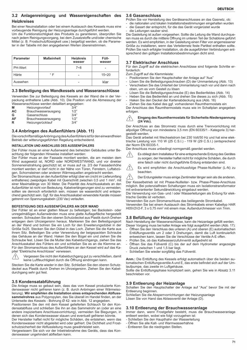
DEUTSCH
71
DEUTSCH
71
3.2 Anlagenreinigung und Wassereigenschaften des Heizkreises Bei einer Neuinstallation oder bei einem Austausch des Kessels muss eine vorbeugende Reinigung der Heizungsanlage durchgeführt werden. Um die Funktionstüchtigkeit des Produkts zu garantieren, überprüfen Sie nach jedem Reinigungsvorgang, bei dem Zusatzstoffe und/oder chemische Mittel (z. B. Frostschutz üssigkeit usw.) beigefügt werden, ob die Parame-ter in der Tabelle mit den angegebenen Werten übereinstimmen.
Parameter Maßeinheit Heizkreiswasser
Füll-wasser
PH-Wert 7÷8 -
Härte ° F - 15÷20
Aussehen - klar
3.3 Befestigung des Wandkessels und Wasseranschlüsse Verwenden Sie zur Befestigung des Kessels an der Wand die in der Ver-packung enthaltene Latte (Abb. 10). Die Position und die Abmessung der Wasseranschlüsse werden detailliert angegeben:M Heizungsvorlauf 3/4”AC Brauchwasserausgang 1/2”G Gasanschluss 3/4”AF Brauchwasserausgang 1/2”R Heizungsrücklauf 3/4”
3.4 Anbringen des Außenfühlers (Abb. 11) Die vorschriftsmäßige Anbringung des Außenfühlers ist für den einwandfreienBetrieb der witterungsgeführten Regelung entscheidend.
INSTALLATION UND ANSCHLUSS DES AUSSENFÜHLERS Der Fühler muss an einer Außenwand des beheizten Gebäudes unter Be-achtung der folgenden Hinweise installiert werden:Der Fühler muss an der Fassade montiert werden, die am meisten dem Wind ausgesetzt ist, NORD oder NORDWESTWAND, und vor direkter Sonneneinstrahlung geschützt ist; er muss auf ca. 2/3 der Fassadenhöhe montiert werden; er darf nicht in der Nähe von Türen, Fenstern, Luftabzü-gen, Schornsteinen oder anderen Wärmequellen angebracht werden.Der Stromanschluss an den Außenfühler erfolgt über ein (nicht im Lieferumfang enthaltenes) zweipoliges Kabel mit Querschnitt zwischen 0,5 und 1 mm2, mit einer Maximallänge von 30 Meter. Die Polarität des Anschlusskabels an den Außenfühler ist nicht von Bedeutung. Kabelverlängerungen sind zu vermeiden; sollten sie dennoch erforderlich sein, müssen sie wasserdicht und entspre-chend geschützt sein. Ggf. für das Anschlusskabel verwendete Kanäle müssen getrennt von Spannungskabeln (230 Vac) verlaufen.
BEFESTIGUNG DES AUSSENFÜHLERS AN DER WAND Der Fühler ist an einer glatten Mauer zu befestigen; bei Backstein- oder unregelmäßigen Außenwänden muss eine glatte Au age äche hergestelltwerden. Schrauben Sie den oberen Schutzdeckel aus Plastik durch Drehen entgegen dem Uhrzeigersinn heraus. Markieren Sie den Befestigungsort an der Wand und bohren Sie ein Loch für den Erweiterungsdübel in der Größe 5x25. Stecken Sie den Dübel in das Loch. Ziehen Sie die Karte aus ihrem Sitz. Befestigen Sie unter Verwendung der beigepackten Schraube das Gehäuse an der Wand. Haken Sie den Bügel ein und ziehen Sie die Schraube fest. Lösen Sie die Mutter des Kabeldurchgangs, ziehen Sie das Anschlusskabel des Fühlers ein und schließen Sie es an die Klemme an. Für den Stromanschluss des Außenfühlers an den Kessel wird auf das Ka-pitel “Elektrische Anschlüsse” verwiesen.
Vergessen Sie nicht den Kabeldurchgang gut zu verschließen, damit keine Luftfeuchtigkeit durch die Öffnung eindringen kann.
Stecken Sie die Karte wieder in den Sitz. Schließen Sie den oberen Schutz-deckel aus Plastik durch Drehen im Uhrzeigersinn. Ziehen Sie den Kabel-durchgang sehr gut fest.
3.5 KondensatabführungDie Anlage muss so gebaut sein, dass das vom Kessel produzierte Kon-denswasser nicht gefrieren kann (z. B. durch Anbringen einer Wärmeiso-lierung). Wir empfehlen die Installation eines entsprechenden Ab uss-sammelrohres aus Polypropylen, das Sie überall im Handel nden, an der Unterseite des Kessels - Bohrung Ø 42- wie in Abb. 12 angegeben.Positionieren Sie den mit dem Kessel gelieferten Schlauch für den Kon-densatab uss und schließen Sie ihn an das Sammelrohr an (oder an eine andere inspizierbare Anschlussvorrichtung), vermeiden Sie Biegungen, in denen sich das Kondenswasser stauen und eventuell gefrieren könnte.Der Hersteller haftet nicht für mögliche Schäden, die entstehen, wenn das Kondenswasser nicht abgeleitet wird oder gefriert. Die Dichtheit und Frost-schutzsicherheit der Ab ussleitung muss gewährleistet sein.Vergewissern Sie sich vor der Inbetriebnahme des Geräts, dass das Kon-denswasser ungehindert ab ießen kann.
3.6 GasanschlussPrüfen Sie vor Herstellung des Geräteanschlusses an das Gasnetz, ob:- die nationalen und lokalen Installationsbestimmungen eingehalten wurden- die Gasart der entspricht, für die das Gerät vorgerüstet wurde- die Leitungen sauber sind.Die Gasleitung ist außen vorgesehen. Sollte die Leitung die Wand durchque-ren muss es durch die mittlere Öffnung im unteren Teil der Schablone geführt werden. Es wird empfohlen, in der Gasleitung einen Filter von angemessener Größe zu installieren, wenn das Verteilernetz feste Partikel enthalten sollte. Prüfen Sie nach erfolgter Installation, ob die ausgeführten Verbindungen ent-sprechend den gültigen Installationsbestimmungen dicht sind.
3.7 Elektrischer AnschlussFür den Zugriff auf die elektrischen Anschlüsse sind folgende Schritte er-forderlich:Zum Zugriff auf die Klemmleiste:- Positionieren Sie den Hauptschalter der Anlage auf “Aus”- Lösen Sie die Befestigungsschrauben (D) der Ummantelung (Abb. 13)- Verschieben Sie das Unterteil der Ummantelung nach vor und dann nach
oben, um es vom Gestell zu lösen- Lösen Sie die Befestigungsschraube (E) des Bedienfeldes (Abb. 14)- Heben Sie das Bedienfeld an und drehen Sie dieses zu sich (Abb. 15)- Haken Sie den Deckel der Kartenabdeckung aus (Abb. 16)- Ziehen Sie das Kabel des ggf. vorhandenen Raumthermostats ein Der Anschluss des Raumthermostats muss wie im Schaltplan angegeben erfolgen.
Eingang des Raumthermostats für Sicherheits-Niederspannung (24 Vdc).
Der Anschluss an das Stromnetz muss durch eine Trennvorrichtung mit allpoliger Öffnung von mindestens 3,5 mm (EN 60335/1 - Kategorie 3) her-gestellt werden. Das Gerät arbeitet mit Wechselstrom bei 230 Volt/50 Hz und hat eine elek-trische Leistung von 110 W (25 C.S.I.) - 119 W (29 C.S.I.) (entsprechend der Norm EN 60335-1.Der Anschluss muss unbedingt normgemäß geerdet werden.
Es obliegt dem Installateur für eine entsprechende Erdung des Gerätes zu sorgen; der Hersteller haftet nicht für mögliche Schäden, die durch eine falsch oder nicht durchgeführte Erdung entstanden sind.
Es wird empfohlen die Anschlussfolge Phase-Nullleiter (L-N) zu beachten.
Der Erdungsleiter muss einige Zentimeter länger sein als die anderen.Der Kesselbetrieb ist mit Phase-Nullleiter- bzw. Phase-Phase-Anschluss möglich. Bei potenzialfreien Schaltungen muss ein Isolationstransformator mit erdverankerter Sekundärwicklung eingebaut werden.Die Verwendung von Gas- und / oder Wasserleitungen als Erdung für elek-trische Geräte ist verboten. Verwenden Sie zum Stromanschluss das beiliegende Stromkabel.Verwenden Sie bei einem Austausch des Stromkabels einen Kabeltyp HAR H05V2V2-F, 3 x 0,75 mm2 mit einem max. Außendurchmesser von 7mm.
3.8 Befüllung der HeizungsanlageNach Herstellung der Wasseranschlüsse, kann die Heizanlage gefüllt werden. Dieser Vorgang muss bei kalter Anlage wie folgt ausgeführt werden (Abb. 17):- Öffnen Sie den Verschluss des unteren (A) und oberen (E) automatischen
Entlüftungsventils um 2 oder 3 Drehungen, damit die Luft kontinuierlich entweichen kann, lassen Sie die Verschlüsse der Ventile A-E offen.
- Prüfen Sie, ob das Kaltwasserzufuhrventil aufgedreht ist- Öffnen Sie das Füllventil (C) bis der auf dem Hydrometer angezeigte
Druck zwischen 1 und 1,5 bar liegt. - Schließen Sie wieder sorgfältig das Füllventil.
Anm.: Die Entlüftung des Kessels erfolgt automatisch über die beiden au-tomatischen Entlüftungsventile A und E, das erste be ndet sich auf der Um-laufpumpe, das zweite im Luftgehäuse.Sollte die Entlüftungsphase kompliziert sein, gehen Sie wie in Absatz 3.11 beschrieben vor.
3.9 Entleerung der HeizanlageSchalten Sie den Hauptschalter der Anlage auf “Aus” bevor Sie mit der Entleerung beginnen.Schließen Sie die Absperrvorrichtungen der HeizungsanlageLösen Sie von Hand das Ablassventil der Anlage (D).
3.10 Entleerung der BrauchwasseranlageImmer dann, wenn Frostgefahr besteht, muss die Brauchwasseranlage entleert werden, wobei wie folgt vorzugehen ist:- Schließen Sie den Haupthahn der Wasserleitung- Öffnen Sie alle Kalt- und Warmwasserhähne- Entleeren Sie die niedrigsten Stellen.
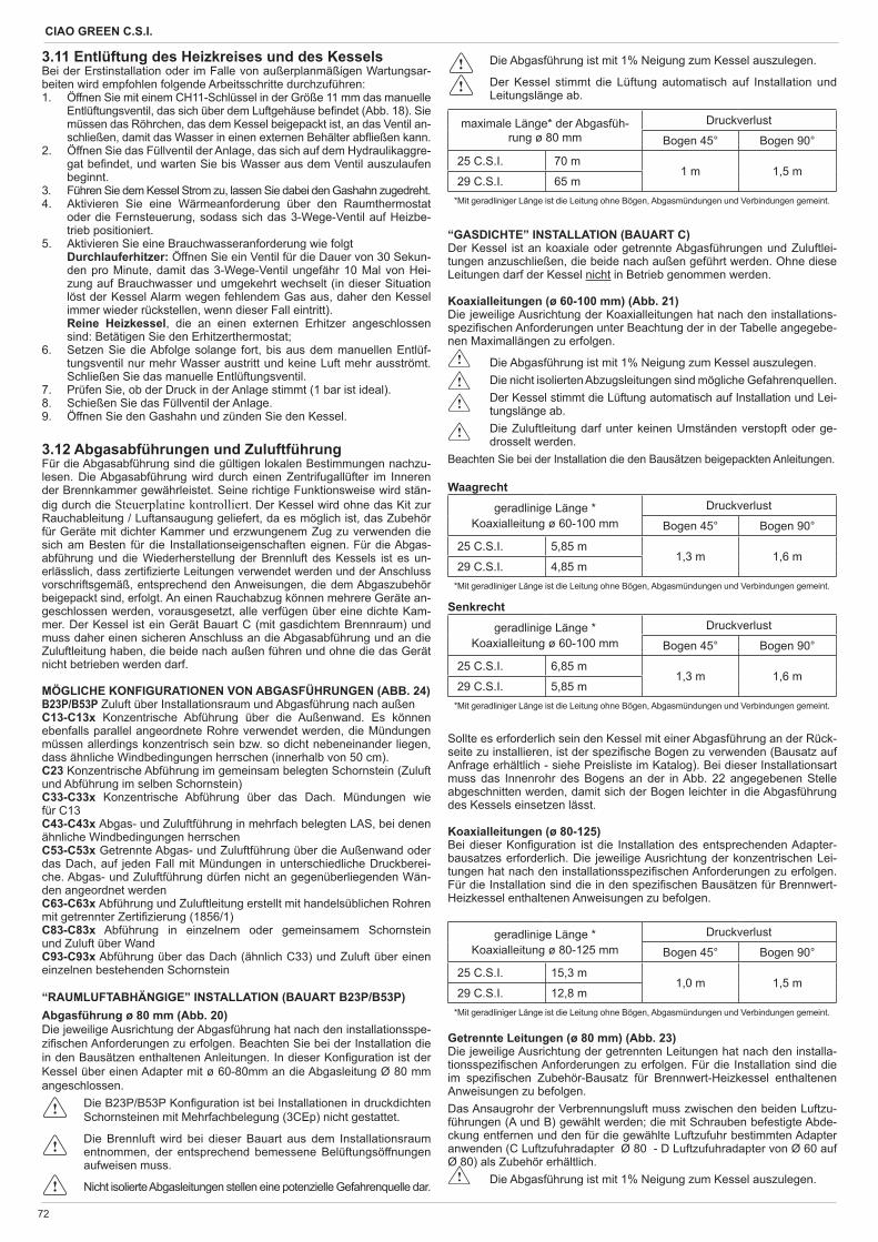
CIAO GREEN C.S.I.
72
3.11 Entlüftung des Heizkreises und des Kessels Bei der Erstinstallation oder im Falle von außerplanmäßigen Wartungsar-beiten wird empfohlen folgende Arbeitsschritte durchzuführen:1. Öffnen Sie mit einem CH11-Schlüssel in der Größe 11 mm das manuelle
Entlüftungsventil, das sich über dem Luftgehäuse be ndet (Abb. 18). Sie müssen das Röhrchen, das dem Kessel beigepackt ist, an das Ventil an-schließen, damit das Wasser in einen externen Behälter ab ießen kann.
2. Öffnen Sie das Füllventil der Anlage, das sich auf dem Hydraulikaggre-gat be ndet, und warten Sie bis Wasser aus dem Ventil auszulaufen beginnt.
3. Führen Sie dem Kessel Strom zu, lassen Sie dabei den Gashahn zugedreht.4. Aktivieren Sie eine Wärmeanforderung über den Raumthermostat
oder die Fernsteuerung, sodass sich das 3-Wege-Ventil auf Heizbe-trieb positioniert.
5. Aktivieren Sie eine Brauchwasseranforderung wie folgt Durchlauferhitzer: Öffnen Sie ein Ventil für die Dauer von 30 Sekun-
den pro Minute, damit das 3-Wege-Ventil ungefähr 10 Mal von Hei-zung auf Brauchwasser und umgekehrt wechselt (in dieser Situation löst der Kessel Alarm wegen fehlendem Gas aus, daher den Kessel immer wieder rückstellen, wenn dieser Fall eintritt).
Reine Heizkessel, die an einen externen Erhitzer angeschlossen sind: Betätigen Sie den Erhitzerthermostat;
6. Setzen Sie die Abfolge solange fort, bis aus dem manuellen Entlüf-tungsventil nur mehr Wasser austritt und keine Luft mehr ausströmt. Schließen Sie das manuelle Entlüftungsventil.
7. Prüfen Sie, ob der Druck in der Anlage stimmt (1 bar ist ideal).8. Schießen Sie das Füllventil der Anlage.9. Öffnen Sie den Gashahn und zünden Sie den Kessel.
3.12 Abgasabführungen und ZuluftführungFür die Abgasabführung sind die gültigen lokalen Bestimmungen nachzu-lesen. Die Abgasabführung wird durch einen Zentrifugallüfter im Inneren der Brennkammer gewährleistet. Seine richtige Funktionsweise wird stän-dig durch die Steuerplatine kontrolliert. Der Kessel wird ohne das Kit zur Rauchableitung / Luftansaugung geliefert, da es möglich ist, das Zubehör für Geräte mit dichter Kammer und erzwungenem Zug zu verwenden die sich am Besten für die Installationseigenschaften eignen. Für die Abgas-abführung und die Wiederherstellung der Brennluft des Kessels ist es un-erlässlich, dass zerti zierte Leitungen verwendet werden und der Anschluss vorschriftsgemäß, entsprechend den Anweisungen, die dem Abgaszubehör beigepackt sind, erfolgt. An einen Rauchabzug können mehrere Geräte an-geschlossen werden, vorausgesetzt, alle verfügen über eine dichte Kam-mer. Der Kessel ist ein Gerät Bauart C (mit gasdichtem Brennraum) und muss daher einen sicheren Anschluss an die Abgasabführung und an die Zuluftleitung haben, die beide nach außen führen und ohne die das Gerät nicht betrieben werden darf.
MÖGLICHE KONFIGURATIONEN VON ABGASFÜHRUNGEN (ABB. 24)B23P/B53P Zuluft über Installationsraum und Abgasführung nach außenC13-C13x Konzentrische Abführung über die Außenwand. Es können ebenfalls parallel angeordnete Rohre verwendet werden, die Mündungen müssen allerdings konzentrisch sein bzw. so dicht nebeneinander liegen, dass ähnliche Windbedingungen herrschen (innerhalb von 50 cm).C23 Konzentrische Abführung im gemeinsam belegten Schornstein (Zuluft und Abführung im selben Schornstein)C33-C33x Konzentrische Abführung über das Dach. Mündungen wiefür C13C43-C43x Abgas- und Zuluftführung in mehrfach belegten LAS, bei denen ähnliche Windbedingungen herrschenC53-C53x Getrennte Abgas- und Zuluftführung über die Außenwand oder das Dach, auf jeden Fall mit Mündungen in unterschiedliche Druckberei-che. Abgas- und Zuluftführung dürfen nicht an gegenüberliegenden Wän-den angeordnet werdenC63-C63x Abführung und Zuluftleitung erstellt mit handelsüblichen Rohren mit getrennter Zerti zierung (1856/1)C83-C83x Abführung in einzelnem oder gemeinsamem Schornsteinund Zuluft über WandC93-C93x Abführung über das Dach (ähnlich C33) und Zuluft über einen einzelnen bestehenden Schornstein
“RAUMLUFTABHÄNGIGE” INSTALLATION (BAUART B23P/B53P)Abgasführung ø 80 mm (Abb. 20)Die jeweilige Ausrichtung der Abgasführung hat nach den installationsspe-zi schen Anforderungen zu erfolgen. Beachten Sie bei der Installation die in den Bausätzen enthaltenen Anleitungen. In dieser Kon guration ist der Kessel über einen Adapter mit ø 60-80mm an die Abgasleitung Ø 80 mm angeschlossen.
Die B23P/B53P Kon guration ist bei Installationen in druckdichten Schornsteinen mit Mehrfachbelegung (3CEp) nicht gestattet.
Die Brennluft wird bei dieser Bauart aus dem Installationsraum entnommen, der entsprechend bemessene Belüftungsöffnungen aufweisen muss.
Nicht isolierte Abgasleitungen stellen eine potenzielle Gefahrenquelle dar.
Die Abgasführung ist mit 1% Neigung zum Kessel auszulegen.
Der Kessel stimmt die Lüftung automatisch auf Installation und Leitungslänge ab.
maximale Länge* der Abgasfüh-rung ø 80 mm
Druckverlust
Bogen 45° Bogen 90°
25 C.S.I. 70 m1 m 1,5 m
29 C.S.I. 65 m*Mit geradliniger Länge ist die Leitung ohne Bögen, Abgasmündungen und Verbindungen gemeint.
“GASDICHTE” INSTALLATION (BAUART C) Der Kessel ist an koaxiale oder getrennte Abgasführungen und Zuluftlei-tungen anzuschließen, die beide nach außen geführt werden. Ohne diese Leitungen darf der Kessel nicht in Betrieb genommen werden.
Koaxialleitungen (ø 60-100 mm) (Abb. 21)Die jeweilige Ausrichtung der Koaxialleitungen hat nach den installations-spezi schen Anforderungen unter Beachtung der in der Tabelle angegebe-nen Maximallängen zu erfolgen.
Die Abgasführung ist mit 1% Neigung zum Kessel auszulegen. Die nicht isolierten Abzugsleitungen sind mögliche Gefahrenquellen. Der Kessel stimmt die Lüftung automatisch auf Installation und Lei-
tungslänge ab. Die Zuluftleitung darf unter keinen Umständen verstopft oder ge-
drosselt werden.Beachten Sie bei der Installation die den Bausätzen beigepackten Anleitungen.
Waagrecht
geradlinige Länge *Koaxialleitung ø 60-100 mm
Druckverlust
Bogen 45° Bogen 90°
25 C.S.I. 5,85 m1,3 m 1,6 m
29 C.S.I. 4,85 m*Mit geradliniger Länge ist die Leitung ohne Bögen, Abgasmündungen und Verbindungen gemeint.
Senkrecht
geradlinige Länge *Koaxialleitung ø 60-100 mm
Druckverlust
Bogen 45° Bogen 90°
25 C.S.I. 6,85 m1,3 m 1,6 m
29 C.S.I. 5,85 m*Mit geradliniger Länge ist die Leitung ohne Bögen, Abgasmündungen und Verbindungen gemeint.
Sollte es erforderlich sein den Kessel mit einer Abgasführung an der Rück-seite zu installieren, ist der spezi sche Bogen zu verwenden (Bausatz auf Anfrage erhältlich - siehe Preisliste im Katalog). Bei dieser Installationsart muss das Innenrohr des Bogens an der in Abb. 22 angegebenen Stelle abgeschnitten werden, damit sich der Bogen leichter in die Abgasführung des Kessels einsetzen lässt.
Koaxialleitungen (ø 80-125)Bei dieser Kon guration ist die Installation des entsprechenden Adapter-bausatzes erforderlich. Die jeweilige Ausrichtung der konzentrischen Lei-tungen hat nach den installationsspezi schen Anforderungen zu erfolgen. Für die Installation sind die in den spezi schen Bausätzen für Brennwert-Heizkessel enthaltenen Anweisungen zu befolgen.
geradlinige Länge * Koaxialleitung ø 80-125 mm
Druckverlust
Bogen 45° Bogen 90°
25 C.S.I. 15,3 m1,0 m 1,5 m
29 C.S.I. 12,8 m*Mit geradliniger Länge ist die Leitung ohne Bögen, Abgasmündungen und Verbindungen gemeint.
Getrennte Leitungen (ø 80 mm) (Abb. 23)Die jeweilige Ausrichtung der getrennten Leitungen hat nach den installa-tionsspezi schen Anforderungen zu erfolgen. Für die Installation sind die im spezi schen Zubehör-Bausatz für Brennwert-Heizkessel enthaltenen Anweisungen zu befolgen.Das Ansaugrohr der Verbrennungsluft muss zwischen den beiden Luftzu-führungen (A und B) gewählt werden; die mit Schrauben befestigte Abde-ckung entfernen und den für die gewählte Luftzufuhr bestimmten Adapter anwenden (C Luftzufuhradapter Ø 80 - D Luftzufuhradapter von Ø 60 auf Ø 80) als Zubehör erhältlich.
Die Abgasführung ist mit 1% Neigung zum Kessel auszulegen.
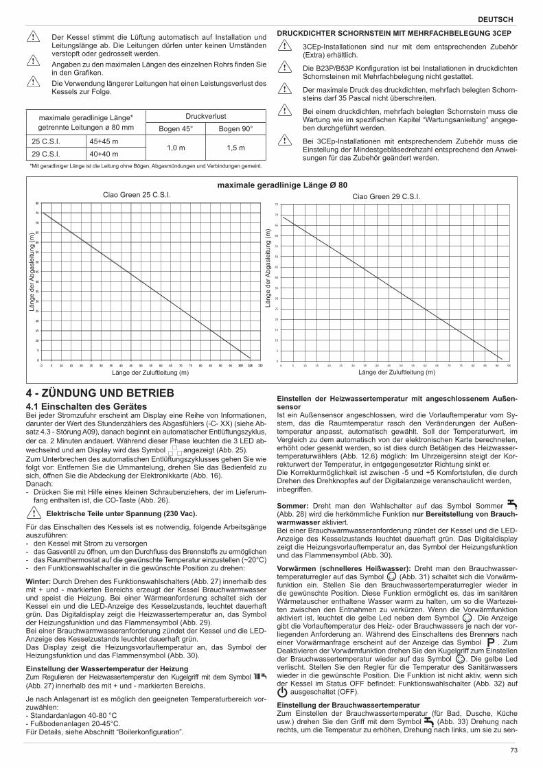
DEUTSCH
73
4 - ZÜNDUNG UND BETRIEB4.1 Einschalten des GerätesBei jeder Stromzufuhr erscheint am Display eine Reihe von Informationen, darunter der Wert des Stundenzählers des Abgasfühlers (-C- XX) (siehe Ab-satz 4.3 - Störung A09), danach beginnt ein automatischer Entlüftungszyklus, der ca. 2 Minuten andauert. Während dieser Phase leuchten die 3 LED ab-wechselnd und am Display wird das Symbol angezeigt (Abb. 25). Zum Unterbrechen des automatischen Entlüftungszyklusses gehen Sie wie folgt vor: Entfernen Sie die Ummantelung, drehen Sie das Bedienfeld zu sich, öffnen Sie die Abdeckung der Elektronikkarte (Abb. 16).Danach:- Drücken Sie mit Hilfe eines kleinen Schraubenziehers, der im Lieferum-
fang enthalten ist, die CO-Taste (Abb. 26).
Elektrische Teile unter Spannung (230 Vac).
Für das Einschalten des Kessels ist es notwendig, folgende Arbeitsgänge auszuführen:- den Kessel mit Strom zu versorgen- das Gasventil zu öffnen, um den Durch uss des Brennstoffs zu ermöglichen - das Raumthermostat auf die gewünschte Temperatur einzustellen (~20°C)- den Funktionswahlschalter in die gewünschte Position zu drehen:
Winter: Durch Drehen des Funktionswahlschalters (Abb. 27) innerhalb des mit + und - markierten Bereichs erzeugt der Kessel Brauchwarmwasser und speist die Heizung. Bei einer Wärmeanforderung schaltet sich der Kessel ein und die LED-Anzeige des Kesselzustands, leuchtet dauerhaft grün. Das Digitaldisplay zeigt die Heizwassertemperatur an, das Symbol der Heizungsfunktion und das Flammensymbol (Abb. 29).Bei einer Brauchwarmwasseranforderung zündet der Kessel und die LED-Anzeige des Kesselzustands leuchtet dauerhaft grün.Das Display zeigt die Heizungsvorlauftemperatur an, das Symbol der Heizungsfunktion und das Flammensymbol (Abb. 30).
Einstellung der Wassertemperatur der Heizung Zum Regulieren der Heizwassertemperatur den Kugelgriff mit dem Symbol (Abb. 27) innerhalb des mit + und - markierten Bereichs.
Je nach Anlagenart ist es möglich den geeigneten Temperaturbereich vor-zuwählen:- Standardanlagen 40-80 °C- Fußbodenanlagen 20-45°C.Für Details, siehe Abschnitt “Boilerkon guration”.
Länge der Zuluftleitung (m)
Läng
e de
r Abg
asle
itung
(m)
80
0
5
10
15
20
25
30
35
40
45
50
55
60
65
70
75
0 5 10 15 20 25 30 35 40 45 50 55 60 65 70 75 80 85 90 95 100100 105105 1101100
5
10
15
20
25
30
35
40
45
50
55
60
65
70
75
0 5 10 15 20 25 30 35 40 45 50 55 60 65 70 75 80 85 90 95
maximale geradlinige Länge Ø 80Ciao Green 25 C.S.I. Ciao Green 29 C.S.I.
Länge der Zuluftleitung (m)
Läng
e de
r Abg
asle
itung
(m)
Der Kessel stimmt die Lüftung automatisch auf Installation und Leitungslänge ab. Die Leitungen dürfen unter keinen Umständen verstopft oder gedrosselt werden.
Angaben zu den maximalen Längen des einzelnen Rohrs nden Sie in den Gra ken.
Die Verwendung längerer Leitungen hat einen Leistungsverlust des Kessels zur Folge.
maximale geradlinige Länge* getrennte Leitungen ø 80 mm
Druckverlust
Bogen 45° Bogen 90°
25 C.S.I. 45+45 m1,0 m 1,5 m
29 C.S.I. 40+40 m*Mit geradliniger Länge ist die Leitung ohne Bögen, Abgasmündungen und Verbindungen gemeint.
DRUCKDICHTER SCHORNSTEIN MIT MEHRFACHBELEGUNG 3CEP
3CEp-Installationen sind nur mit dem entsprechenden Zubehör (Extra) erhältlich.
Die B23P/B53P Kon guration ist bei Installationen in druckdichten Schornsteinen mit Mehrfachbelegung nicht gestattet.
Der maximale Druck des druckdichten, mehrfach belegten Schorn-steins darf 35 Pascal nicht überschreiten.
Bei einem druckdichten, mehrfach belegten Schornstein muss die Wartung wie im spezi schen Kapitel “Wartungsanleitung” angege-ben durchgeführt werden.
Bei 3CEp-Installationen mit entsprechendem Zubehör muss die Einstellung der Mindestgebläsedrehzahl entsprechend den Anwei-sungen für das Zubehör geändert werden.
Einstellen der Heizwassertemperatur mit angeschlossenem Außen-sensorIst ein Außensensor angeschlossen, wird die Vorlauftemperatur vom Sy-stem, das die Raumtemperatur rasch den Veränderungen der Außen-temperatur anpasst, automatisch gewählt. Soll der Temperaturwert, im Vergleich zu dem automatisch von der elektronischen Karte berechneten, erhöht oder gesenkt werden, so ist dies durch Betätigen des Heizwasser-temperaturwählers (Abb. 12.6) möglich: Im Uhrzeigersinn steigt der Kor-rekturwert der Temperatur, in entgegengesetzter Richtung sinkt er.Die Korrekturmöglichkeit ist zwischen -5 und +5 Komfortstufen, die durch Drehen des Drehknopfes auf der Digitalanzeige veranschaulicht werden,inbegriffen.
Sommer: Dreht man den Wahlschalter auf das Symbol Sommer (Abb. 28) wird die herkömmliche Funktion nur Bereitstellung von Brauch-warmwasser aktiviert. Bei einer Brauchwarmwasseranforderung zündet der Kessel und die LED-Anzeige des Kesselzustands leuchtet dauerhaft grün. Das Digitaldisplay zeigt die Heizungsvorlauftemperatur an, das Symbol der Heizungsfunktion und das Flammensymbol (Abb. 30).
Vorwärmen (schnelleres Heißwasser): Dreht man den Brauchwasser-temperaturregler auf das Symbol (Abb. 31) schaltet sich die Vorwärm-funktion ein. Stellen Sie den Brauchwassertemperaturregler wieder in die gewünschte Position. Diese Funktion ermöglicht es, das im sanitären Wärmetauscher enthaltene Wasser warm zu halten, um so die Wartezei-ten zwischen den Entnahmen zu verkürzen. Wenn die Vorwärmfunktion aktiviert ist, leuchtet die gelbe Led neben dem Symbol . Die Anzeige gibt die Vorlauftemperatur des Heiz- oder Brauchwassers je nach der vor-liegenden Anforderung an. Während des Einschaltens des Brenners nach einer Vorwärmanfrage erscheint auf der Anzeige das Symbol . Zum Deaktivieren der Vorwärmfunktion drehen Sie den Kugelgriff zum Einstellen der Brauchwassertemperatur wieder auf das Symbol . Die gelbe Led verlischt. Stellen Sie den Regler für die Temperatur des Sanitärwassers wieder in die gewünschte Position. Die Funktion ist nicht aktiv, wenn sich der Kessel im Status OFF be ndet: Funktionswahlschalter (Abb. 32) auf
ausgeschaltet (OFF).
Einstellung der BrauchwassertemperaturZum Einstellen der Brauchwassertemperatur (für Bad, Dusche, Küche usw.) drehen Sie den Griff mit dem Symbol (Abb. 33) Drehung nach rechts, um die Temperatur zu erhöhen, Drehung nach links, um sie zu sen-
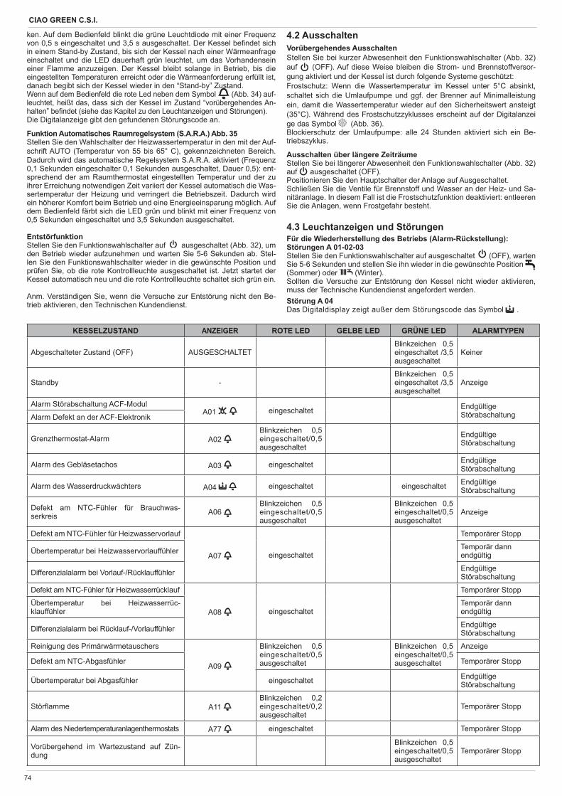
CIAO GREEN C.S.I.
74
4.2 AusschaltenVorübergehendes AusschaltenStellen Sie bei kurzer Abwesenheit den Funktionswahlschalter (Abb. 32) auf (OFF). Auf diese Weise bleiben die Strom- und Brennstoffversor-gung aktiviert und der Kessel ist durch folgende Systeme geschützt:Frostschutz: Wenn die Wassertemperatur im Kessel unter 5°C absinkt, schaltet sich die Umlaufpumpe und ggf. der Brenner auf Minimalleistung ein, damit die Wassertemperatur wieder auf den Sicherheitswert ansteigt (35°C). Während des Frostschutzzyklusses erscheint auf der Digitalanzei ge das Symbol (Abb. 36).Blockierschutz der Umlaufpumpe: alle 24 Stunden aktiviert sich ein Be-triebszyklus.
Ausschalten über längere ZeiträumeStellen Sie bei längerer Abwesenheit den Funktionswahlschalter (Abb. 32) auf ausgeschaltet (OFF).Positionieren Sie den Hauptschalter der Anlage auf Ausgeschaltet.Schließen Sie die Ventile für Brennstoff und Wasser an der Heiz- und Sa-nitäranlage. In diesem Fall ist die Frostschutzfunktion deaktiviert: entleeren Sie die Anlagen, wenn Frostgefahr besteht.
4.3 Leuchtanzeigen und StörungenFür die Wiederherstellung des Betriebs (Alarm-Rückstellung):Störungen A 01-02-03Stellen Sie den Funktionswahlschalter auf ausgeschaltet (OFF), warten Sie 5-6 Sekunden und stellen Sie ihn wieder in die gewünschte Position (Sommer) oder (Winter).Sollten die Versuche zur Entstörung den Kessel nicht wieder aktivieren, muss der Technische Kundendienst angefordert werden.Störung A 04Das Digitaldisplay zeigt außer dem Störungscode das Symbol .
ken. Auf dem Bedienfeld blinkt die grüne Leuchtdiode mit einer Frequenz von 0,5 s eingeschaltet und 3,5 s ausgeschaltet. Der Kessel be ndet sich in einem Stand-by Zustand, bis sich der Kessel nach einer Wärmeanfrage einschaltet und die LED dauerhaft grün leuchtet, um das Vorhandensein einer Flamme anzuzeigen. Der Kessel bleibt solange in Betrieb, bis die eingestellten Temperaturen erreicht oder die Wärmeanforderung erfüllt ist, danach begibt sich der Kessel wieder in den “Stand-by” Zustand.Wenn auf dem Bedienfeld die rote Led neben dem Symbol (Abb. 34) auf-leuchtet, heißt das, dass sich der Kessel im Zustand “vorübergehendes An-halten” be ndet (siehe das Kapitel zu den Leuchtanzeigen und Störungen).Die Digitalanzeige gibt den gefundenen Störungscode an.
Funktion Automatisches Raumregelsystem (S.A.R.A.) Abb. 35Stellen Sie den Wahlschalter der Heizwassertemperatur in den mit der Auf-schrift AUTO (Temperatur von 55 bis 65° C), gekennzeichneten Bereich. Dadurch wird das automatische Regelsystem S.A.R.A. aktiviert (Frequenz 0,1 Sekunden eingeschalter 0,1 Sekunden ausgeschaltet, Dauer 0,5): ent-sprechend der am Raumthermostat eingestellten Temperatur und der zu ihrer Erreichung notwendigen Zeit variiert der Kessel automatisch die Was-sertemperatur der Heizung und verringert die Betriebszeit. Dadurch wird ein höherer Komfort beim Betrieb und eine Energieeinsparung möglich. Auf dem Bedienfeld färbt sich die LED grün und blinkt mit einer Frequenz von 0,5 Sekunden eingeschaltet und 3,5 Sekunden ausgeschaltet.
EntstörfunktionStellen Sie den Funktionswahlschalter auf ausgeschaltet (Abb. 32), um den Betrieb wieder aufzunehmen und warten Sie 5-6 Sekunden ab. Stel-len Sie den Funktionswahlschalter wieder in die gewünschte Position und prüfen Sie, ob die rote Kontrollleuchte ausgeschaltet ist. Jetzt startet der Kessel automatisch neu und die rote Kontrollleuchte schaltet sich grün ein.
Anm. Verständigen Sie, wenn die Versuche zur Entstörung nicht den Be-trieb aktivieren, den Technischen Kundendienst.
KESSELZUSTAND ANZEIGER ROTE LED GELBE LED GRÜNE LED ALARMTYPEN
Abgeschalteter Zustand (OFF) AUSGESCHALTETBlinkzeichen 0,5 eingeschaltet /3,5 ausgeschaltet
Keiner
Standby -Blinkzeichen 0,5 eingeschaltet /3,5 ausgeschaltet
Anzeige
Alarm Störabschaltung ACF-ModulA01 eingeschaltet Endgültige
StörabschaltungAlarm Defekt an der ACF-Elektronik
Grenzthermostat-Alarm A02 Blinkzeichen 0,5 eingeschaltet/0,5 ausgeschaltet
EndgültigeStörabschaltung
Alarm des Gebläsetachos A03 eingeschaltet EndgültigeStörabschaltung
Alarm des Wasserdruckwächters A04 eingeschaltet eingeschaltet EndgültigeStörabschaltung
Defekt am NTC-Fühler für Brauchwas-serkreis A06
Blinkzeichen 0,5 eingeschaltet/0,5 ausgeschaltet
Blinkzeichen 0,5 eingeschaltet/0,5 ausgeschaltet
Anzeige
Defekt am NTC-Fühler für Heizwasservorlauf
A07 eingeschaltet
Temporärer Stopp
Übertemperatur bei Heizwasservorlauffühler Temporär dann endgültig
Differenzialalarm bei Vorlauf-/Rücklauffühler EndgültigeStörabschaltung
Defekt am NTC-Fühler für Heizwasserrücklauf
A08 eingeschaltet
Temporärer Stopp
Übertemperatur bei Heizwasserrüc-klauffühler
Temporär dann endgültig
Differenzialalarm bei Rücklauf-/Vorlauffühler EndgültigeStörabschaltung
Reinigung des Primärwärmetauschers
A09
Blinkzeichen 0,5 eingeschaltet/0,5 ausgeschaltet
Blinkzeichen 0,5 eingeschaltet/0,5 ausgeschaltet
Anzeige
Defekt am NTC-Abgasfühler Temporärer Stopp
Übertemperatur bei Abgasfühler eingeschaltet EndgültigeStörabschaltung
Stör amme A11 Blinkzeichen 0,2 eingeschaltet/0,2 ausgeschaltet
Temporärer Stopp
Alarm des Niedertemperaturanlagenthermostats A77 eingeschaltet Temporärer Stopp
Vorübergehend im Wartezustand auf Zün-dung
Blinkzeichen 0,5 eingeschaltet/0,5 ausgeschaltet
Temporärer Stopp
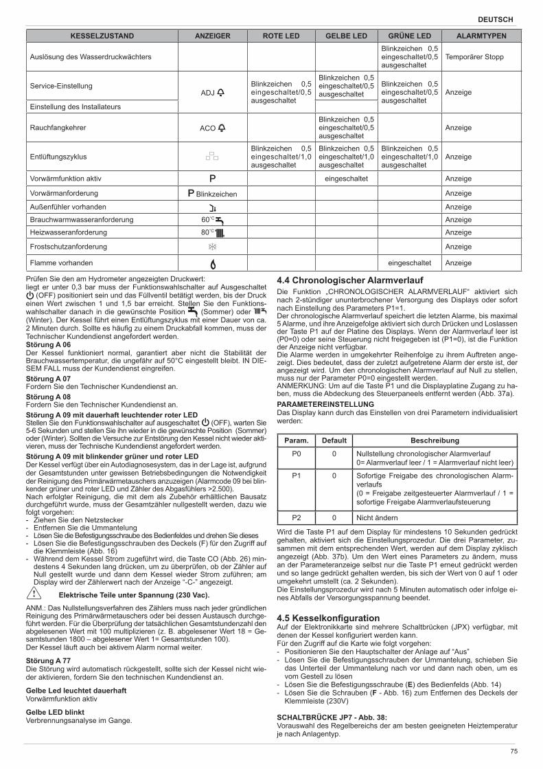
DEUTSCH
75
Prüfen Sie den am Hydrometer angezeigten Druckwert:liegt er unter 0,3 bar muss der Funktionswahlschalter auf Ausgeschaltet
(OFF) positioniert sein und das Füllventil betätigt werden, bis der Druck einen Wert zwischen 1 und 1,5 bar erreicht. Stellen Sie den Funktions-wahlschalter danach in die gewünschte Position (Sommer) oder (Winter). Der Kessel führt einen Entlüftungszyklus mit einer Dauer von ca. 2 Minuten durch. Sollte es häu g zu einem Druckabfall kommen, muss der Technischer Kundendienst angefordert werden.Störung A 06Der Kessel funktioniert normal, garantiert aber nicht die Stabilität der Brauchwassertemperatur, die ungefähr auf 50°C eingestellt bleibt. IN DIE-SEM FALL muss der Kundendienst eingreifen.Störung A 07Fordern Sie den Technischer Kundendienst an.Störung A 08Fordern Sie den Technischer Kundendienst an.Störung A 09 mit dauerhaft leuchtender roter LEDStellen Sie den Funktionswahlschalter auf ausgeschaltet (OFF), warten Sie 5-6 Sekunden und stellen Sie ihn wieder in die gewünschte Position (Sommer) oder (Winter). Sollten die Versuche zur Entstörung den Kessel nicht wieder akti-vieren, muss der Technische Kundendienst angefordert werden.Störung A 09 mit blinkender grüner und roter LED Der Kessel verfügt über ein Autodiagnosesystem, das in der Lage ist, aufgrund der Gesamtstunden unter gewissen Betriebsbedingungen die Notwendigkeit der Reinigung des Primärwärmetauschers anzuzeigen (Alarmcode 09 bei blin-kender grüner und roter LED und Zähler des Abgasfühlers >2.500). Nach erfolgter Reinigung, die mit dem als Zubehör erhältlichen Bausatz durchgeführt wurde, muss der Gesamtzähler nullgestellt werden, dazu wie folgt vorgehen: - Ziehen Sie den Netzstecker- Entfernen Sie die Ummantelung - Lösen Sie die Befestigungsschraube des Bedienfeldes und drehen Sie dieses- Lösen Sie die Befestigungsschrauben des Deckels (F) für den Zugriff auf
die Klemmleiste (Abb. 16) - Während dem Kessel Strom zugeführt wird, die Taste CO (Abb. 26) min-
destens 4 Sekunden lang drücken, um zu überprüfen, ob der Zähler auf Null gestellt wurde und dann dem Kessel wieder Strom zuführen; am Display wird der Zählerwert nach der Anzeige “-C-” angezeigt.
Elektrische Teile unter Spannung (230 Vac).
ANM.: Das Nullstellungsverfahren des Zählers muss nach jeder gründlichen Reinigung des Primärwärmetauschers oder bei dessen Austausch durchge-führt werden. Für die Überprüfung der tatsächlichen Gesamtstundenzahl den abgelesenen Wert mit 100 multiplizieren (z. B. abgelesener Wert 18 = Ge-samtstunden 1800 – abgelesener Wert 1= Gesamtstunden 100).Der Kessel läuft auch bei aktivem Alarm normal weiter.
Störung A 77Die Störung wird automatisch rückgestellt, sollte sich der Kessel nicht wie-der aktivieren, fordern Sie den technischen Kundendienst an.
Gelbe Led leuchtet dauerhaftVorwärmfunktion aktiv
Gelbe LED blinktVerbrennungsanalyse im Gange.
4.4 Chronologischer Alarmverlauf Die Funktion „CHRONOLOGISCHER ALARMVERLAUF“ aktiviert sich nach 2-stündiger ununterbrochener Versorgung des Displays oder sofort nach Einstellung des Parameters P1=1.Der chronologische Alarmverlauf speichert die letzten Alarme, bis maximal 5 Alarme, und ihre Anzeigefolge aktiviert sich durch Drücken und Loslassen der Taste P1 auf der Platine des Displays. Wenn der Alarmverlauf leer ist (P0=0) oder seine Steuerung nicht freigegeben ist (P1=0), ist die Funktion der Anzeige nicht verfügbar.Die Alarme werden in umgekehrter Reihenfolge zu ihrem Auftreten ange-zeigt. Dies bedeutet, dass der zuletzt aufgetretene Alarm der erste ist, der angezeigt wird. Um den chronologischen Alarmverlauf auf Null zu stellen, muss nur der Parameter P0=0 eingestellt werden.ANMERKUNG: Um auf die Taste P1 und die Displayplatine Zugang zu ha-ben, muss die Abdeckung des Steuerpaneels entfernt werden (Abb. 37a).PARAMETEREINSTELLUNGDas Display kann durch das Einstellen von drei Parametern individualisiert werden:
Param. Default Beschreibung
P0 0 Nullstellung chronologischer Alarmverlauf0= Alarmverlauf leer / 1 = Alarmverlauf nicht leer)
P1 0 Sofortige Freigabe des chronologischen Alarm-verlaufs(0 = Freigabe zeitgesteuerter Alarmverlauf / 1 = sofortige Freigabe Alarmverlaufsteuerung
P2 0 Nicht ändern
Wird die Taste P1 auf dem Display für mindestens 10 Sekunden gedrückt gehalten, aktiviert sich die Einstellungsprozedur. Die drei Parameter, zu-sammen mit dem entsprechenden Wert, werden auf dem Display zyklisch angezeigt (Abb. 37b). Um den Wert eines Parameters zu ändern, muss an der Parameteranzeige selbst nur die Taste P1 erneut gedrückt werden und so lange gedrückt gehalten werden, bis sich der Wert von 0 auf 1 oder umgekehrt umstellt (ca. 2 Sekunden).Die Einstellungsprozedur wird nach 5 Minuten automatisch oder infolge ei-nes Abfalls der Versorgungsspannung beendet.
4.5 Kesselkon guration Auf der Elektronikkarte sind mehrere Schaltbrücken (JPX) verfügbar, mit denen der Kessel kon guriert werden kann.Für den Zugriff auf die Karte wie folgt vorgehen:- Positionieren Sie den Hauptschalter der Anlage auf “Aus”- Lösen Sie die Befestigungsschrauben der Ummantelung, schieben Sie
das Unterteil der Ummantelung nach vor und dann nach oben, um es vom Gestell zu lösen
- Lösen Sie die Befestigungsschraube (E) des Bedienfelds (Abb. 14) - Lösen Sie die Schrauben (F - Abb. 16) zum Entfernen des Deckels der
Klemmleiste (230V)
SCHALTBRÜCKE JP7 - Abb. 38: Vorauswahl des Regelbereichs der am besten geeigneten Heiztemperatur je nach Anlagentyp.
KESSELZUSTAND ANZEIGER ROTE LED GELBE LED GRÜNE LED ALARMTYPEN
Auslösung des WasserdruckwächtersBlinkzeichen 0,5 eingeschaltet/0,5 ausgeschaltet
Temporärer Stopp
Service-EinstellungADJ
Blinkzeichen 0,5 eingeschaltet/0,5 ausgeschaltet
Blinkzeichen 0,5 eingeschaltet/0,5 ausgeschaltet
Blinkzeichen 0,5 eingeschaltet/0,5 ausgeschaltet
Anzeige
Einstellung des Installateurs
Rauchfangkehrer ACO Blinkzeichen 0,5 eingeschaltet/0,5 ausgeschaltet
Anzeige
EntlüftungszyklusBlinkzeichen 0,5 eingeschaltet/1,0 ausgeschaltet
Blinkzeichen 0,5 eingeschaltet/1,0 ausgeschaltet
Blinkzeichen 0,5 eingeschaltet/1,0 ausgeschaltet
Anzeige
Vorwärmfunktion aktiv eingeschaltet Anzeige
Vorwärmanforderung Blinkzeichen Anzeige
Außenfühler vorhanden Anzeige
Brauchwarmwasseranforderung 60°C Anzeige
Heizwasseranforderung 80°C Anzeige
Frostschutzanforderung Anzeige
Flamme vorhanden eingeschaltet Anzeige
CIAO GREEN C.S.I.
76
Schaltbrücke nicht eingefügt - StandardanlageStandardanlage 40-80 °CSchaltbrücke eingefügt - FußbodenanlageFußbodenanlage 20-45 °C.Werkseitig wurde der Kessel für Standardanlagen kon guriert.
JP1 Einstellung (Range Rated)JP2 Nullstellung HeizungstimerJP3 Einstellung (siehe Absatz “Einstellungen”)JP4 Wahlschalter absolute BrauchwasserthermostateJP5 nicht verwenden JP6 Aktivierung der Funktion Nachtabsenkung und Pumpe in Dauerbetrieb
(nur bei angeschlossenem Außenfühler)JP7 Aktivierung der Steuerung für Standard-/Niedertemperaturanlagen (sie-
he oben) JP8 nicht verwenden
4.6 Einstellung der Temperaturregelung (Gra ken 1-2-3)Die Temperaturregelung funktioniert nur bei angeschlossenem Außenfüh-ler, deshalb muss der - als Zubehör auf Anfrage erhältliche - Außenfühler nach der Installation an die vorgesehenen Anschlüsse an der Klemmleis-te des Kessels angeschlossen werden (Abb. 5). Auf diese Weise wird die Funktion TEMPERATURREGELUNG aktiviert.Auswahl der KompensationskurveDie Kompensationsheizkurve sorgt dafür, dass bei Außentemperaturen im Bereich -20 bis +20°C eine theoretische Raumtemperatur von 20°C gehal-ten wird. Die Festlegung der Heizkurve hängt von der min. Soll-Außentem-peratur (d.h. vom Installationsort) und der Soll-Vorlauftemperatur (d.h. vom Anlagentyp) ab, wobei die Berechnung der Kurve durch den Installateur nach folgender Formel erfolgen muss:
Tshift = 30°C Standardanlagen 25°C Fußbodenanlagen Wenn sich aus der Berechnung ein Zwischenwert zwischen zwei Kurven ergibt, emp ehlt es sich die Kompensationskurve zu wählen, die näher am erzielten Wert liegt. Beispiel: ergibt sich aus der Berechnung ein Wert von 1,3 liegt dieser zwischen der Kurve 1 und der Kurve 1,5. In diesem Fall die näher gelegene Kurve wählen, also 1,5. Die Auswahl des KT muss durch Betätigen des auf der Platine vorhandenen Trimmers P3 durchgeführt wer-den (siehe feindrähtiger Schaltplan).Für den Zugriff auf P3:- Entfernen Sie die Ummantelung - Lösen Sie die Befestigungsschraube des Bedienfelds- Drehen Sie die Bedienfeld zu sich- Lösen Sie die Befestigungsschrauben des Deckels der Klemmleiste- Lösen Sie die Abdeckung der Karte
Elektrische Teile unter Spannung (230 Vac).
Folgende KT-Werte sind einstellbar:Standardanlage: 1,0-1,5-2,0-2,5-3,0Fußbodenanlage 0,2-0,4-0,6-0,8 und werden für die Dauer von ca. 3 Sekunden nach dem Drehen des Trim-mers P3 am Display angezeigt.
ART DER WÄRMEANFORDERUNGBei Anschluss eines Raumthermostats an den Kessel (SCHALTBRÜ-CKE 6 nicht eingefügt)Die Wärmeanforderung erfolgt durch Schließen des Kontakts des Raum-thermostats, die Öffnung des Kontakts bewirkt hingegen die Abschaltung. Die Vorlauftemperatur wird vom Kessel automatisch berechnet, lässt sich aber durch den Benutzer ändern. Aktiviert man die Schnittstelle zum Än-dern der HEIZUNG ist der HEIZ-SOLLWERT nicht verfügbar, sondern ein Wert, der nach Belieben zwischen 15 e 25°C eingestellt werden kann. Der Eingriff auf diesen Wert ändert nicht direkt die Vorlauftemperatur, sondern wirkt sich auf die Berechnung aus, die den Vorlaufwert durch Ändern der Bezugstemperatur im System (0 = 20°C). automatisch bestimmt.Bei Anschluss einer Programmuhr an den Kessel (SCHALTBRÜCKE JP6 eingefügt)Bei geschlossenem Kontakt wird die Wärmeanforderung vom Vorlauffühler aufgrund der Außentemperatur durchgeführt, um eine Nenn-Raumtempe-ratur auf der Stufe TAG (20 °C) zu haben. Das Öffnen des Kontakts be-stimmt nicht das Abschalten, sondern eine Absenkung (Parallelverschie-bung) der Heizkurve auf die Stufe NACHT (16 °C). Auf diese Weise wird die Nachtabsenkung aktiviert. Die Vorlauftemperatur wird vom Kessel auto-matisch berechnet, lässt sich aber durch den Benutzer ändern. Aktiviert man die Schnittstelle zum Ändern der HEIZUNG ist der HEI-ZUNGSSOLLWERT nicht verfügbar, sondern ein Wert, der nach Belieben zwischen 25 e 15°C eingestellt werden kann. Der Eingriff auf diesen Wert ändert nicht direkt die Vorlauftemperatur sondern wirkt sich auf die Berech-nung aus, die den Vorlaufwert durch Ändern der Bezugstemperatur im Sys-tem (0 = 20°C, für die Stufe TAG, 16 °C für die Stufe NACHT). automatisch bestimmt.
4.7 EinstellungenDer Kessel wurde bereits während der Produktion vom Hersteller eingestellt. Sollte es jedoch notwendig sein, die Einstellungen erneut durchzuführen, wie zum Beispiel nach einer außergewöhnlichen Wartung, nach dem Austausch des Gasventils oder nach einer Umrüstung von Erdgas auf Flüssiggas, füh-ren Sie die nachfolgend beschriebenen Arbeitsgänge aus.Die Einstellungen für Mindest- und Höchstleistung, für maximale Heizwas-sertemperatur und Langsamzündung müssen unbedingt in der angegebe-nen Reihenfolge und ausschließlich von quali ziertem Personal durchge-führt werden:- Trennen Sie die Stromzufuhr zum Kessel- Stellen Sie den Wahlschalter für die Heizwassertemperatur auf den
Höchstwert - Lösen Sie die Befestigungsschraube (E) des Bedienfelds (Abb. 14)- Heben Sie das Bedienfeld an und drehen Sie dieses zu sich - Lösen Sie die Befestigungsschrauben des Deckels (F) für den Zugriff auf
die Klemmleiste (Abb. 16) - Fügen Sie die Schaltbrücken JP1 und JP3 ein (Abb. 40)- Führen Sie dem Kessel Strom zuDie 3 LED auf dem Bedienfeld blinken gleichzeitig und das Display zeigt ca. 4 Sekunden lang “ADJ” an Ändern Sie die folgenden Parameter:1 - Absoluter/Brauchwasser Maximalwert2 - Mindestwert3 - Maximalwert für Heizung4 - Langsamzündungwie nachfolgend beschrieben:- Drehen Sie den Wahlschalter für die Heizwassertemperatur, um den ge-
wünschten Wert einzustellen. - Drücken Sie mit Hilfe eines kleinen Schraubenziehers, der im Lieferum-
fang enthalten ist, die CO-Taste (Abb. 26) und nehmen Sie die Einstel-lung des nächsten Parameters vor.
Elektrische Teile unter Spannung (230 Vac).
Am Display leuchten die folgenden Symbole auf:1. während der Einstellung des absoluten/Brauchwasser Maximalwertes2. während der Einstellung des Mindestwertes3. während der Einstellung des Maximalwertes für die Heizung4. während der Einstellung Langsamzündung
Beenden Sie den Vorgang durch Entfernen der Schaltbrücken JP1 und JP3 zum Speichern der auf diese Weise eingestellten Werte.Die Funktion kann zu jedem beliebigen Moment unter Beibehaltung der ur-sprünglichen Werte ohne Speichern der eingestellten Werte beendet werden:- durch Entfernen der Schaltbrücken JP1 und JP3, bevor alle 4 Parameter
eingestellt wurden- durch Stellen des Funktionswahlschalters auf OFF/RESET - durch Trennen der Stromzufuhr - 15 Minuten nach der Aktivierung.
Die Einstellung bewirkt nicht das Zünden des Kessels. Durch Drehen des Kugelgriffs für die Auswahl Heizung wird auto-
matisch am Display die Anzahl an Umdrehungen ausgedrückt in Hundert angezeigt (Beispiel 25 = 2500 U/Min).
Bei 3CEp-Installationen mit entsprechendem Zubehör muss die Einstellung der Mindestgebläsedrehzahl entsprechend den An-weisungen für das Zubehör geändert werden.
Die Anzeige der Einstellungsparameter wird mit dem Funktionsschalter Sommer oder Winter aktiviert, indem die auf der Karte vorhandene Taste CO gedrückt wird, unabhängig davon, ob Wärme angefordert wird oder nicht.Die Funktion kann nicht aktiviert werden, wenn eine Fernsteuerung ange-schlossen ist.Wenn die Funktion aktiviert ist, werden die Einstellungsparameter in der unten angegebenen Reihenfolge für 2 Sekunden angezeigt. Neben jedem Parameter werden das entsprechende Symbol und die in Hunderten aus-gedrückte Drehzahl des Ventilators angezeigt.1. Maximal 2. Minimal 3. Heizung maximal 4. Langsame Einschaltung P5. Maximale Heizung reguliert
EINSTELLUNG DES GASVENTILS- Führen Sie dem Kessel Strom zu- Öffnen Sie den Gashahn- Stellen Sie den Funktionswahlschalter auf OFF/RESET (Display aus-
geschaltet)- Entfernen Sie die Ummantelung, senken Sie das Bedienfeld zu sich hin,
nachdem Sie die Schraube (E) gelöst haben (Abb. 14)- Lösen Sie die Befestigungsschrauben des Deckels (F) für den Zugriff auf
die Klemmleiste (Abb. 16) - Drücken Sie mit Hilfe eines kleinen Schraubenziehers, der im Lieferum-
fang enthalten ist, die CO-Taste (Abb. 26).
Soll-Vorlauftemperatur - TshiftKT= 20- min. Soll-Außentemperatur
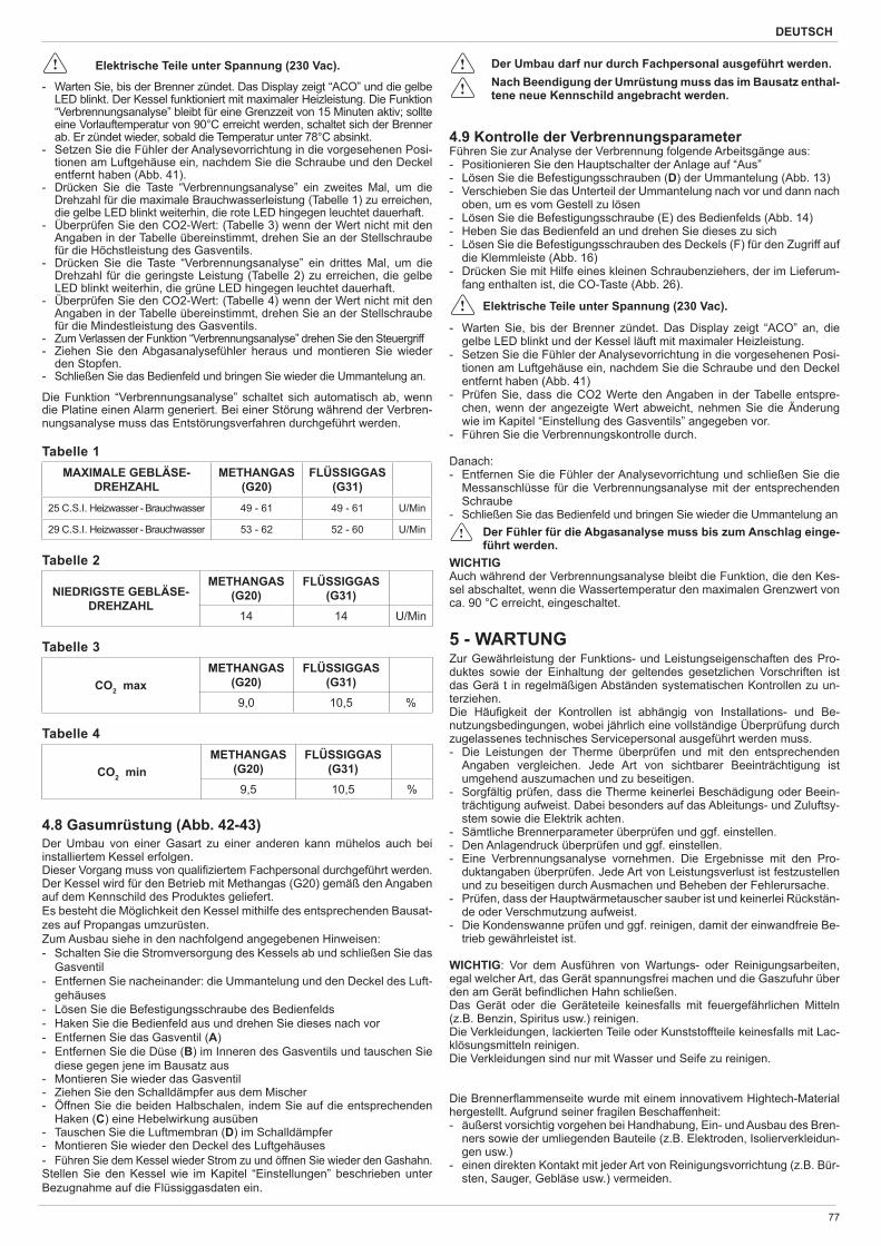
DEUTSCH
77
Elektrische Teile unter Spannung (230 Vac).
- Warten Sie, bis der Brenner zündet. Das Display zeigt “ACO” und die gelbe LED blinkt. Der Kessel funktioniert mit maximaler Heizleistung. Die Funktion “Verbrennungsanalyse” bleibt für eine Grenzzeit von 15 Minuten aktiv; sollte eine Vorlauftemperatur von 90°C erreicht werden, schaltet sich der Brenner ab. Er zündet wieder, sobald die Temperatur unter 78°C absinkt.
- Setzen Sie die Fühler der Analysevorrichtung in die vorgesehenen Posi-tionen am Luftgehäuse ein, nachdem Sie die Schraube und den Deckel entfernt haben (Abb. 41).
- Drücken Sie die Taste “Verbrennungsanalyse” ein zweites Mal, um die Drehzahl für die maximale Brauchwasserleistung (Tabelle 1) zu erreichen, die gelbe LED blinkt weiterhin, die rote LED hingegen leuchtet dauerhaft.
- Überprüfen Sie den CO2-Wert: (Tabelle 3) wenn der Wert nicht mit den Angaben in der Tabelle übereinstimmt, drehen Sie an der Stellschraube für die Höchstleistung des Gasventils.
- Drücken Sie die Taste “Verbrennungsanalyse” ein drittes Mal, um die Drehzahl für die geringste Leistung (Tabelle 2) zu erreichen, die gelbe LED blinkt weiterhin, die grüne LED hingegen leuchtet dauerhaft.
- Überprüfen Sie den CO2-Wert: (Tabelle 4) wenn der Wert nicht mit den Angaben in der Tabelle übereinstimmt, drehen Sie an der Stellschraube für die Mindestleistung des Gasventils.
- Zum Verlassen der Funktion “Verbrennungsanalyse” drehen Sie den Steuergriff- Ziehen Sie den Abgasanalysefühler heraus und montieren Sie wieder
den Stopfen.- Schließen Sie das Bedienfeld und bringen Sie wieder die Ummantelung an.
Die Funktion “Verbrennungsanalyse” schaltet sich automatisch ab, wenn die Platine einen Alarm generiert. Bei einer Störung während der Verbren-nungsanalyse muss das Entstörungsverfahren durchgeführt werden.
Tabelle 1MAXIMALE GEBLÄSE-
DREHZAHL METHANGAS
(G20)FLÜSSIGGAS
(G31)
25 C.S.I. Heizwasser - Brauchwasser 49 - 61 49 - 61 U/Min
29 C.S.I. Heizwasser - Brauchwasser 53 - 62 52 - 60 U/Min
Tabelle 2
NIEDRIGSTE GEBLÄSE-DREHZAHL
METHANGAS (G20)
FLÜSSIGGAS (G31)
14 14 U/Min
Tabelle 3
CO2 maxMETHANGAS
(G20)FLÜSSIGGAS
(G31)9,0 10,5 %
Tabelle 4
CO2 minMETHANGAS
(G20)FLÜSSIGGAS
(G31)9,5 10,5 %
4.8 Gasumrüstung (Abb. 42-43)Der Umbau von einer Gasart zu einer anderen kann mühelos auch bei installiertem Kessel erfolgen.Dieser Vorgang muss von quali ziertem Fachpersonal durchgeführt werden.Der Kessel wird für den Betrieb mit Methangas (G20) gemäß den Angaben auf dem Kennschild des Produktes geliefert.Es besteht die Möglichkeit den Kessel mithilfe des entsprechenden Bausat-zes auf Propangas umzurüsten.Zum Ausbau siehe in den nachfolgend angegebenen Hinweisen:- Schalten Sie die Stromversorgung des Kessels ab und schließen Sie das
Gasventil- Entfernen Sie nacheinander: die Ummantelung und den Deckel des Luft-
gehäuses- Lösen Sie die Befestigungsschraube des Bedienfelds- Haken Sie die Bedienfeld aus und drehen Sie dieses nach vor- Entfernen Sie das Gasventil (A)- Entfernen Sie die Düse (B) im Inneren des Gasventils und tauschen Sie
diese gegen jene im Bausatz aus- Montieren Sie wieder das Gasventil- Ziehen Sie den Schalldämpfer aus dem Mischer- Öffnen Sie die beiden Halbschalen, indem Sie auf die entsprechenden
Haken (C) eine Hebelwirkung ausüben- Tauschen Sie die Luftmembran (D) im Schalldämpfer - Montieren Sie wieder den Deckel des Luftgehäuses- Führen Sie dem Kessel wieder Strom zu und öffnen Sie wieder den Gashahn.Stellen Sie den Kessel wie im Kapitel “Einstellungen” beschrieben unter Bezugnahme auf die Flüssiggasdaten ein.
Der Umbau darf nur durch Fachpersonal ausgeführt werden. Nach Beendigung der Umrüstung muss das im Bausatz enthal-
tene neue Kennschild angebracht werden.
4.9 Kontrolle der VerbrennungsparameterFühren Sie zur Analyse der Verbrennung folgende Arbeitsgänge aus: - Positionieren Sie den Hauptschalter der Anlage auf “Aus” - Lösen Sie die Befestigungsschrauben (D) der Ummantelung (Abb. 13) - Verschieben Sie das Unterteil der Ummantelung nach vor und dann nach
oben, um es vom Gestell zu lösen - Lösen Sie die Befestigungsschraube (E) des Bedienfelds (Abb. 14) - Heben Sie das Bedienfeld an und drehen Sie dieses zu sich - Lösen Sie die Befestigungsschrauben des Deckels (F) für den Zugriff auf
die Klemmleiste (Abb. 16) - Drücken Sie mit Hilfe eines kleinen Schraubenziehers, der im Lieferum-
fang enthalten ist, die CO-Taste (Abb. 26).
Elektrische Teile unter Spannung (230 Vac).
- Warten Sie, bis der Brenner zündet. Das Display zeigt “ACO” an, die gelbe LED blinkt und der Kessel läuft mit maximaler Heizleistung.
- Setzen Sie die Fühler der Analysevorrichtung in die vorgesehenen Posi-tionen am Luftgehäuse ein, nachdem Sie die Schraube und den Deckel entfernt haben (Abb. 41)
- Prüfen Sie, dass die CO2 Werte den Angaben in der Tabelle entspre-chen, wenn der angezeigte Wert abweicht, nehmen Sie die Änderung wie im Kapitel “Einstellung des Gasventils” angegeben vor.
- Führen Sie die Verbrennungskontrolle durch.
Danach: - Entfernen Sie die Fühler der Analysevorrichtung und schließen Sie die
Messanschlüsse für die Verbrennungsanalyse mit der entsprechenden Schraube
- Schließen Sie das Bedienfeld und bringen Sie wieder die Ummantelung an Der Fühler für die Abgasanalyse muss bis zum Anschlag einge-
führt werden.WICHTIGAuch während der Verbrennungsanalyse bleibt die Funktion, die den Kes-sel abschaltet, wenn die Wassertemperatur den maximalen Grenzwert von ca. 90 °C erreicht, eingeschaltet.
5 - WARTUNGZur Gewährleistung der Funktions- und Leistungseigenschaften des Pro-duktes sowie der Einhaltung der geltendes gesetzlichen Vorschriften ist das Gerä t in regelmäßigen Abständen systematischen Kontrollen zu un-terziehen.Die Häu gkeit der Kontrollen ist abhängig von Installations- und Be-nutzungsbedingungen, wobei jährlich eine vollständige Überprüfung durch zugelassenes technisches Servicepersonal ausgeführt werden muss. - Die Leistungen der Therme überprüfen und mit den entsprechenden
Angaben vergleichen. Jede Art von sichtbarer Beeinträchtigung ist umgehend auszumachen und zu beseitigen.
- Sorgfältig prüfen, dass die Therme keinerlei Beschädigung oder Beein-trächtigung aufweist. Dabei besonders auf das Ableitungs- und Zuluftsy-stem sowie die Elektrik achten.
- Sämtliche Brennerparameter überprüfen und ggf. einstellen.- Den Anlagendruck überprüfen und ggf. einstellen.- Eine Verbrennungsanalyse vornehmen. Die Ergebnisse mit den Pro-
duktangaben überprüfen. Jede Art von Leistungsverlust ist festzustellen und zu beseitigen durch Ausmachen und Beheben der Fehlerursache.
- Prüfen, dass der Hauptwärmetauscher sauber ist und keinerlei Rückstän-de oder Verschmutzung aufweist.
- Die Kondenswanne prüfen und ggf. reinigen, damit der einwandfreie Be-trieb gewährleistet ist.
WICHTIG: Vor dem Ausführen von Wartungs- oder Reinigungsarbeiten, egal welcher Art, das Gerät spannungsfrei machen und die Gaszufuhr über den am Gerät be ndlichen Hahn schließen.Das Gerät oder die Geräteteile keinesfalls mit feuergefährlichen Mitteln (z.B. Benzin, Spiritus usw.) reinigen.Die Verkleidungen, lackierten Teile oder Kunststoffteile keinesfalls mit Lac-klösungsmitteln reinigen.Die Verkleidungen sind nur mit Wasser und Seife zu reinigen.
Die Brenner ammenseite wurde mit einem innovativem Hightech-Material hergestellt. Aufgrund seiner fragilen Beschaffenheit:- äußerst vorsichtig vorgehen bei Handhabung, Ein- und Ausbau des Bren-
ners sowie der umliegenden Bauteile (z.B. Elektroden, Isolierverkleidun-gen usw.)
- einen direkten Kontakt mit jeder Art von Reinigungsvorrichtung (z.B. Bür-sten, Sauger, Gebläse usw.) vermeiden.
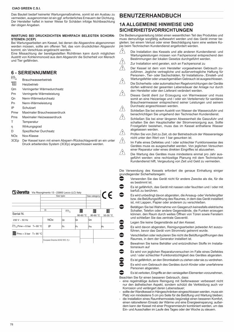
CIAO GREEN C.S.I.
78
Serial N.
230 V ~ 50 Hz NOx:
Pms = 3 bar T= 90 °C
����������� ����������������
Via Risorgimento 13 - 23900 Lecco (LC) ItalyGas type: Gas category:
IPPmw = 6 bar T= 60 °C
D:
80-60 °C 80-60 °C 50-30 °C
Qn
Pn
Qn
Pn
Qm
Pm Pn
Das Bauteil bedarf keinerlei Wartungsmaßnahme, somit ist ein Ausbau zu vermeiden, ausgenommen ist ein ggf. erforderliches Erneuern der Dichtung.Der Hersteller haftet in keiner Weise für Schäden infolge Nichtbeachtung der obigen Angaben.
WARTUNG BEI DRUCKDICHTEN MEHRFACH BELEGTEN SCHORN-STEINEN (3CEP)Bei Wartungsarbeiten am Kessel, bei denen die Abgasrohre abgenommen werden müssen, sollte am offenen Teil, das vom druckdichten Abgasrohr kommt, ein Verschluss angebracht werden.Eine Missachtung der bereitgestellten Richtlinien kann durch möglichen Austritt von Kohlenmonoxid aus dem Abgasrohr die Sicherheit von Mensch und Tier gefährden.
6 - SERIENNUMMER Brauchwasserbetrieb
HeizbetriebQm Verringerter WärmedurchsatzPm Verringerte WärmeleistungQn Nenn-WärmedurchsatzPn Nenn-WärmeleistungIP SchutzartPmw Maximaler BrauchwasserdruckPms Maximaler HeizwasserdruckT Temperatur
WirkungsgradD Spezi scher DurchsatzNOx Nox-Klasse3CEp Der Kessel kann mit einem Absperr-/Rückschlagventil an ein unter
Druck arbeitendes System (3CEp) angeschlossen werden.
BENUTZERHANDBUCH 1A ALLGEMEINE HINWEISE UND SICHERHEITSVORRICHTUNGENDie Bedienungsanleitung bildet einen wesentlichen Teil des Produktes und muss demzufolge sorgfältig aufbewahrt werden und das Gerät immer be-gleiten; bei einem Verlust oder einer Beschädigung kann eine weitere Ko-pie beim Technischen Kundendienst angefordert werden.
Die Installation des Kessels und alle anderen Kundendienst- und Wartungsleistungen müssen von Fachpersonal entsprechend den Bestimmungen der lokalen Gesetze durchgeführt werden.
Zur Installation wird geraten, sich an Fachpersonal zu Der Kessel ist dem vom Hersteller vorgesehenen Gebrauch zu-
zuführen. Jegliche vertragliche und außervertragliche Haftung für Personen-, Tier- oder Sachschäden, für Installations-, Einstell- und Wartungsfehler oder unsachgemäßen Gebrauch ist ausgeschlossen.
Die Sicherheits- oder automatischen Regelvorrichtungen der Geräte dürfen während der gesamten Lebensdauer der Anlage nur durch den Hersteller oder den Lieferant verändert werden.
Dieses Gerät dient zur Erzeugung von Warmwasser und muss somit an eine Heizanlage und / oder ein Verteilernetz für sanitäres Brauchwarmwasser entsprechend seiner Leistungen und seinem Durchsatz angeschlossen werden.
Schließen Sie bei einem Austritt von Wasser die Wasserzufuhr und benachrichtigen Sie umgehend den Technischen Kundendienst.
Schließen Sie bei einer längeren Abwesenheit die Gaszufuhr und schalten Sie den Hauptschalter der Stromversorgung aus. Sollte Frostgefahr bestehen, muss das im Kessel enthaltene Wasser abgelassen werden.
Prüfen Sie von Zeit zu Zeit, ob der Betriebsdruck der Wasseranlage nicht unter den Wert von 1 bar gesunken ist.
Im Falle eines Defektes und / oder schlechter Funktionsweise des Gerätes muss es ausgeschaltet werden. Von jeglichen Versuchen einer Reparatur oder eines direkten Eingriffes ist abzusehen.
Die Wartung des Gerätes muss mindestens einmal pro Jahr aus-geführt werden: eine rechtzeitige Planung mit dem Technischen Kundendienst hilft, Vergeudung von Zeit und Geld zu vermeiden.
Die Verwendung des Kessels erfordert die genaue Einhaltung einiger grundlegender Sicherheitsregeln:
Verwenden Sie das Gerät nicht für andere Zwecke als die, für die es bestimmt ist.
Es ist gefährlich, das Gerät mit nassen oder feuchten und / oder mit barfuß zu berühren.
Es wird unbedingt davon abgeraten, die Ansaug- oder Verteilergitter bzw. die Belüftungsöffnung des Raumes, in dem das Gerät installiert ist, mit Lappen, Papier oder anderem zu verschließen.
Betätigen Sie bei Wahrnahme von Gasgeruch keinesfalls elektrische Schalter, Telefon oder andere Gegenstände, die Funken erzeugen können. den Raum durch weites Öffnen von Türen sowie Fenstern und schließen Sie das zentrale Gasventil.
Legen Sie keine Gegenstände auf den Kessel. Es wird davon abgeraten, Reinigungsarbeiten jedweder Art auszu-
führen, bevor das Gerät vom Stromnetz getrennt wurde. Verschließen oder reduzieren Sie nicht die Belüftungsöffnungen des
Raumes, in dem der Generator installiert ist. Bewahren Sie keine Behälter und entzündlichen Stoffe im Installa-
tionsraum auf Es wird von jeglichen Reparaturversuchen im Falle eines Defektes
und / oder schlechter Funktionstüchtigkeit des Gerätes abgeraten. Es ist gefährlich, an den Stromkabeln zu ziehen oder sie zu verdrehen. Es wird vom Gebrauch des Gerätes durch Kinder oder unerfahrene
Personen abgeraten. Es ist verboten, Eingriffe an den versiegelten Elementen vorzunehmen.
Beachten Sie für einen besseren Gebrauch, dass:- eine regelmäßige äußere Reinigung mit Seifenwasser verbessert nicht
nur den ästhetischen Aspekt, sondern schützt die Verkleidung auch vor Korrosion und verlängert deren Lebensdauer;
- sollte der Wandkessel in Hängeschränken eingeschlossen werden, muss ein Platz von mindestens 5 cm pro Seite für die Belüftung und Wartung bleiben;
- die Installation eines Raumthermostats begünstigt einen besseren Komfort, einen rationelleren Einsatz der Wärme und eine Energieeinsparung; außer-dem kann der Kessel mit einer Programmieruhr kombiniert werden, um das Ein- und Ausschalten im Laufe des Tages oder der Woche zu steuern.
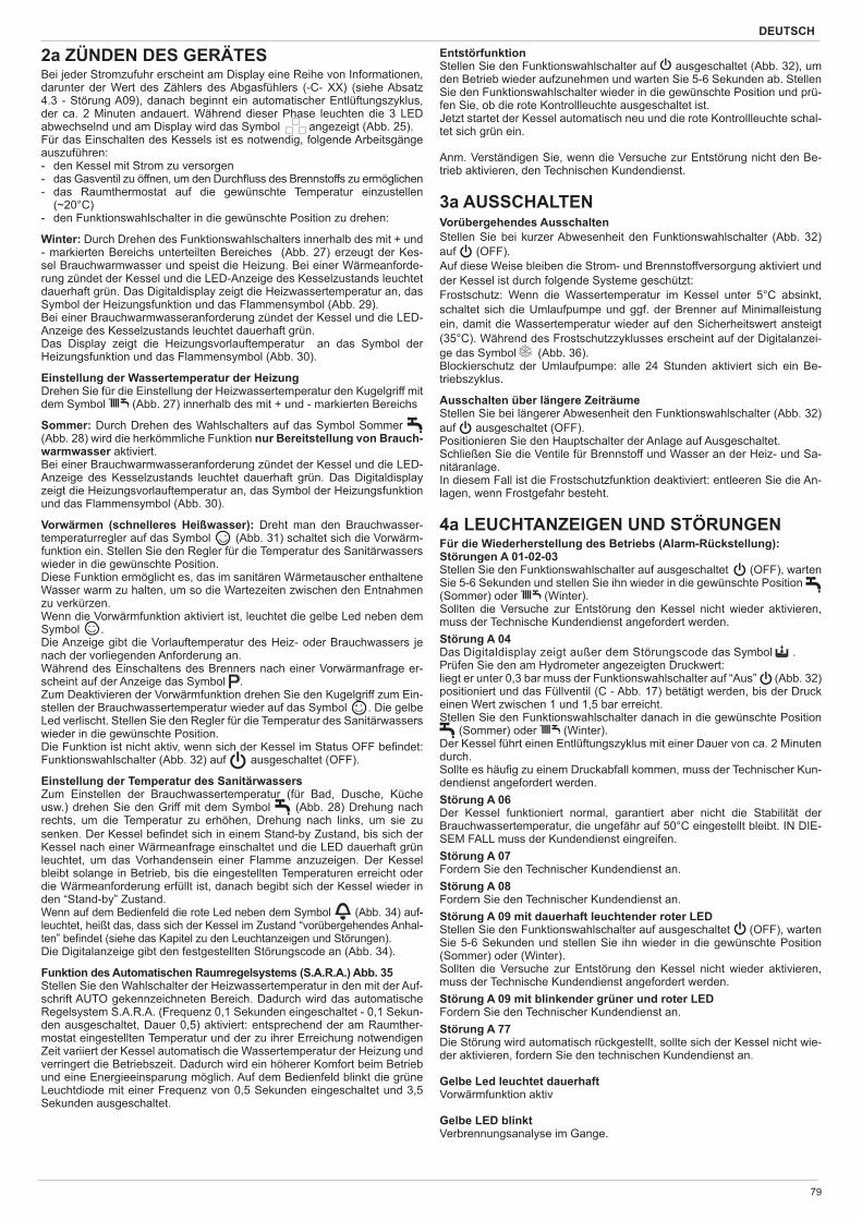
DEUTSCH
79
2a ZÜNDEN DES GERÄTESBei jeder Stromzufuhr erscheint am Display eine Reihe von Informationen, darunter der Wert des Zählers des Abgasfühlers (-C- XX) (siehe Absatz 4.3 - Störung A09), danach beginnt ein automatischer Entlüftungszyklus, der ca. 2 Minuten andauert. Während dieser Phase leuchten die 3 LED abwechselnd und am Display wird das Symbol angezeigt (Abb. 25). Für das Einschalten des Kessels ist es notwendig, folgende Arbeitsgänge auszuführen:- den Kessel mit Strom zu versorgen- das Gasventil zu öffnen, um den Durch uss des Brennstoffs zu ermöglichen - das Raumthermostat auf die gewünschte Temperatur einzustellen
(~20°C)- den Funktionswahlschalter in die gewünschte Position zu drehen:
Winter: Durch Drehen des Funktionswahlschalters innerhalb des mit + und - markierten Bereichs unterteilten Bereiches (Abb. 27) erzeugt der Kes-sel Brauchwarmwasser und speist die Heizung. Bei einer Wärmeanforde-rung zündet der Kessel und die LED-Anzeige des Kesselzustands leuchtet dauerhaft grün. Das Digitaldisplay zeigt die Heizwassertemperatur an, das Symbol der Heizungsfunktion und das Flammensymbol (Abb. 29).Bei einer Brauchwarmwasseranforderung zündet der Kessel und die LED-Anzeige des Kesselzustands leuchtet dauerhaft grün.Das Display zeigt die Heizungsvorlauftemperatur an das Symbol der Heizungsfunktion und das Flammensymbol (Abb. 30).
Einstellung der Wassertemperatur der Heizung Drehen Sie für die Einstellung der Heizwassertemperatur den Kugelgriff mit dem Symbol (Abb. 27) innerhalb des mit + und - markierten Bereichs
Sommer: Durch Drehen des Wahlschalters auf das Symbol Sommer (Abb. 28) wird die herkömmliche Funktion nur Bereitstellung von Brauch-warmwasser aktiviert. Bei einer Brauchwarmwasseranforderung zündet der Kessel und die LED-Anzeige des Kesselzustands leuchtet dauerhaft grün. Das Digitaldisplay zeigt die Heizungsvorlauftemperatur an, das Symbol der Heizungsfunktion und das Flammensymbol (Abb. 30).
Vorwärmen (schnelleres Heißwasser): Dreht man den Brauchwasser-temperaturregler auf das Symbol (Abb. 31) schaltet sich die Vorwärm-funktion ein. Stellen Sie den Regler für die Temperatur des Sanitärwassers wieder in die gewünschte Position.Diese Funktion ermöglicht es, das im sanitären Wärmetauscher enthaltene Wasser warm zu halten, um so die Wartezeiten zwischen den Entnahmen zu verkürzen.Wenn die Vorwärmfunktion aktiviert ist, leuchtet die gelbe Led neben dem Symbol .Die Anzeige gibt die Vorlauftemperatur des Heiz- oder Brauchwassers je nach der vorliegenden Anforderung an.Während des Einschaltens des Brenners nach einer Vorwärmanfrage er-scheint auf der Anzeige das Symbol .Zum Deaktivieren der Vorwärmfunktion drehen Sie den Kugelgriff zum Ein-stellen der Brauchwassertemperatur wieder auf das Symbol . Die gelbe Led verlischt. Stellen Sie den Regler für die Temperatur des Sanitärwassers wieder in die gewünschte Position.Die Funktion ist nicht aktiv, wenn sich der Kessel im Status OFF be ndet: Funktionswahlschalter (Abb. 32) auf ausgeschaltet (OFF).
Einstellung der Temperatur des SanitärwassersZum Einstellen der Brauchwassertemperatur (für Bad, Dusche, Küche usw.) drehen Sie den Griff mit dem Symbol (Abb. 28) Drehung nach rechts, um die Temperatur zu erhöhen, Drehung nach links, um sie zu senken. Der Kessel be ndet sich in einem Stand-by Zustand, bis sich der Kessel nach einer Wärmeanfrage einschaltet und die LED dauerhaft grün leuchtet, um das Vorhandensein einer Flamme anzuzeigen. Der Kessel bleibt solange in Betrieb, bis die eingestellten Temperaturen erreicht oder die Wärmeanforderung erfüllt ist, danach begibt sich der Kessel wieder in den “Stand-by” Zustand.Wenn auf dem Bedienfeld die rote Led neben dem Symbol (Abb. 34) auf-leuchtet, heißt das, dass sich der Kessel im Zustand “vorübergehendes Anhal-ten” be ndet (siehe das Kapitel zu den Leuchtanzeigen und Störungen).Die Digitalanzeige gibt den festgestellten Störungscode an (Abb. 34).
Funktion des Automatischen Raumregelsystems (S.A.R.A.) Abb. 35Stellen Sie den Wahlschalter der Heizwassertemperatur in den mit der Auf-schrift AUTO gekennzeichneten Bereich. Dadurch wird das automatische Regelsystem S.A.R.A. (Frequenz 0,1 Sekunden eingeschaltet - 0,1 Sekun-den ausgeschaltet, Dauer 0,5) aktiviert: entsprechend der am Raumther-mostat eingestellten Temperatur und der zu ihrer Erreichung notwendigen Zeit variiert der Kessel automatisch die Wassertemperatur der Heizung und verringert die Betriebszeit. Dadurch wird ein höherer Komfort beim Betrieb und eine Energieeinsparung möglich. Auf dem Bedienfeld blinkt die grüne Leuchtdiode mit einer Frequenz von 0,5 Sekunden eingeschaltet und 3,5 Sekunden ausgeschaltet.
EntstörfunktionStellen Sie den Funktionswahlschalter auf ausgeschaltet (Abb. 32), um den Betrieb wieder aufzunehmen und warten Sie 5-6 Sekunden ab. Stellen Sie den Funktionswahlschalter wieder in die gewünschte Position und prü-fen Sie, ob die rote Kontrollleuchte ausgeschaltet ist.Jetzt startet der Kessel automatisch neu und die rote Kontrollleuchte schal-tet sich grün ein.
Anm. Verständigen Sie, wenn die Versuche zur Entstörung nicht den Be-trieb aktivieren, den Technischen Kundendienst.
3a AUSSCHALTENVorübergehendes AusschaltenStellen Sie bei kurzer Abwesenheit den Funktionswahlschalter (Abb. 32) auf (OFF).Auf diese Weise bleiben die Strom- und Brennstoffversorgung aktiviert und der Kessel ist durch folgende Systeme geschützt:Frostschutz: Wenn die Wassertemperatur im Kessel unter 5°C absinkt, schaltet sich die Umlaufpumpe und ggf. der Brenner auf Minimalleistung ein, damit die Wassertemperatur wieder auf den Sicherheitswert ansteigt (35°C). Während des Frostschutzzyklusses erscheint auf der Digitalanzei-ge das Symbol (Abb. 36).Blockierschutz der Umlaufpumpe: alle 24 Stunden aktiviert sich ein Be-triebszyklus.
Ausschalten über längere ZeiträumeStellen Sie bei längerer Abwesenheit den Funktionswahlschalter (Abb. 32) auf ausgeschaltet (OFF).Positionieren Sie den Hauptschalter der Anlage auf Ausgeschaltet.Schließen Sie die Ventile für Brennstoff und Wasser an der Heiz- und Sa-nitäranlage.In diesem Fall ist die Frostschutzfunktion deaktiviert: entleeren Sie die An-lagen, wenn Frostgefahr besteht.
4a LEUCHTANZEIGEN UND STÖRUNGENFür die Wiederherstellung des Betriebs (Alarm-Rückstellung):Störungen A 01-02-03Stellen Sie den Funktionswahlschalter auf ausgeschaltet (OFF), warten Sie 5-6 Sekunden und stellen Sie ihn wieder in die gewünschte Position (Sommer) oder (Winter).Sollten die Versuche zur Entstörung den Kessel nicht wieder aktivieren, muss der Technische Kundendienst angefordert werden.Störung A 04Das Digitaldisplay zeigt außer dem Störungscode das Symbol .Prüfen Sie den am Hydrometer angezeigten Druckwert:liegt er unter 0,3 bar muss der Funktionswahlschalter auf “Aus” (Abb. 32) positioniert und das Füllventil (C - Abb. 17) betätigt werden, bis der Druck einen Wert zwischen 1 und 1,5 bar erreicht.Stellen Sie den Funktionswahlschalter danach in die gewünschte Position
(Sommer) oder (Winter).Der Kessel führt einen Entlüftungszyklus mit einer Dauer von ca. 2 Minuten durch. Sollte es häu g zu einem Druckabfall kommen, muss der Technischer Kun-dendienst angefordert werden.Störung A 06Der Kessel funktioniert normal, garantiert aber nicht die Stabilität der Brauchwassertemperatur, die ungefähr auf 50°C eingestellt bleibt. IN DIE-SEM FALL muss der Kundendienst eingreifen.Störung A 07Fordern Sie den Technischer Kundendienst an.Störung A 08Fordern Sie den Technischer Kundendienst an.Störung A 09 mit dauerhaft leuchtender roter LEDStellen Sie den Funktionswahlschalter auf ausgeschaltet (OFF), warten Sie 5-6 Sekunden und stellen Sie ihn wieder in die gewünschte Position (Sommer) oder (Winter).Sollten die Versuche zur Entstörung den Kessel nicht wieder aktivieren, muss der Technische Kundendienst angefordert werden.Störung A 09 mit blinkender grüner und roter LEDFordern Sie den Technischer Kundendienst an.Störung A 77Die Störung wird automatisch rückgestellt, sollte sich der Kessel nicht wie-der aktivieren, fordern Sie den technischen Kundendienst an.
Gelbe Led leuchtet dauerhaftVorwärmfunktion aktiv
Gelbe LED blinktVerbrennungsanalyse im Gange.
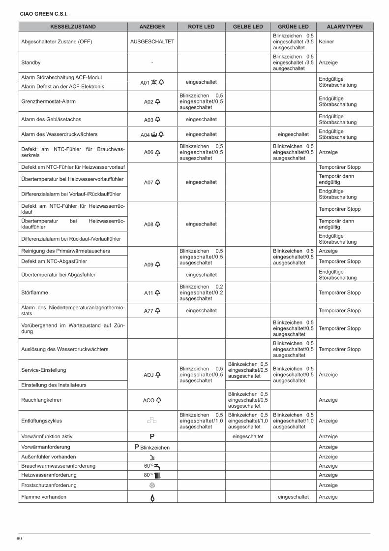
CIAO GREEN C.S.I.
80
KESSELZUSTAND ANZEIGER ROTE LED GELBE LED GRÜNE LED ALARMTYPEN
Abgeschalteter Zustand (OFF) AUSGESCHALTETBlinkzeichen 0,5 eingeschaltet /3,5 ausgeschaltet
Keiner
Standby -Blinkzeichen 0,5 eingeschaltet /3,5 ausgeschaltet
Anzeige
Alarm Störabschaltung ACF-ModulA01 eingeschaltet Endgültige
StörabschaltungAlarm Defekt an der ACF-Elektronik
Grenzthermostat-Alarm A02 Blinkzeichen 0,5 eingeschaltet/0,5 ausgeschaltet
EndgültigeStörabschaltung
Alarm des Gebläsetachos A03 eingeschaltet EndgültigeStörabschaltung
Alarm des Wasserdruckwächters A04 eingeschaltet eingeschaltet EndgültigeStörabschaltung
Defekt am NTC-Fühler für Brauchwas-serkreis A06
Blinkzeichen 0,5 eingeschaltet/0,5 ausgeschaltet
Blinkzeichen 0,5 eingeschaltet/0,5 ausgeschaltet
Anzeige
Defekt am NTC-Fühler für Heizwasservorlauf
A07 eingeschaltet
Temporärer Stopp
Übertemperatur bei Heizwasservorlauffühler Temporär dann endgültig
Differenzialalarm bei Vorlauf-/Rücklauffühler EndgültigeStörabschaltung
Defekt am NTC-Fühler für Heizwasserrüc-klauf
A08 eingeschaltet
Temporärer Stopp
Übertemperatur bei Heizwasserrüc-klauffühler
Temporär dann endgültig
Differenzialalarm bei Rücklauf-/Vorlauffühler EndgültigeStörabschaltung
Reinigung des Primärwärmetauschers
A09
Blinkzeichen 0,5 eingeschaltet/0,5 ausgeschaltet
Blinkzeichen 0,5 eingeschaltet/0,5 ausgeschaltet
Anzeige
Defekt am NTC-Abgasfühler Temporärer Stopp
Übertemperatur bei Abgasfühler eingeschaltet EndgültigeStörabschaltung
Stör amme A11 Blinkzeichen 0,2 eingeschaltet/0,2 ausgeschaltet
Temporärer Stopp
Alarm des Niedertemperaturanlagenthermo-stats A77 eingeschaltet Temporärer Stopp
Vorübergehend im Wartezustand auf Zün-dung
Blinkzeichen 0,5 eingeschaltet/0,5 ausgeschaltet
Temporärer Stopp
Auslösung des WasserdruckwächtersBlinkzeichen 0,5 eingeschaltet/0,5 ausgeschaltet
Temporärer Stopp
Service-EinstellungADJ
Blinkzeichen 0,5 eingeschaltet/0,5 ausgeschaltet
Blinkzeichen 0,5 eingeschaltet/0,5 ausgeschaltet
Blinkzeichen 0,5 eingeschaltet/0,5 ausgeschaltet
Anzeige
Einstellung des Installateurs
Rauchfangkehrer ACO Blinkzeichen 0,5 eingeschaltet/0,5 ausgeschaltet
Anzeige
EntlüftungszyklusBlinkzeichen 0,5 eingeschaltet/1,0 ausgeschaltet
Blinkzeichen 0,5 eingeschaltet/1,0 ausgeschaltet
Blinkzeichen 0,5 eingeschaltet/1,0 ausgeschaltet
Anzeige
Vorwärmfunktion aktiv eingeschaltet Anzeige
Vorwärmanforderung Blinkzeichen Anzeige
Außenfühler vorhanden Anzeige
Brauchwarmwasseranforderung 60°C Anzeige
Heizwasseranforderung 80°C Anzeige
Frostschutzanforderung Anzeige
Flamme vorhanden eingeschaltet Anzeige
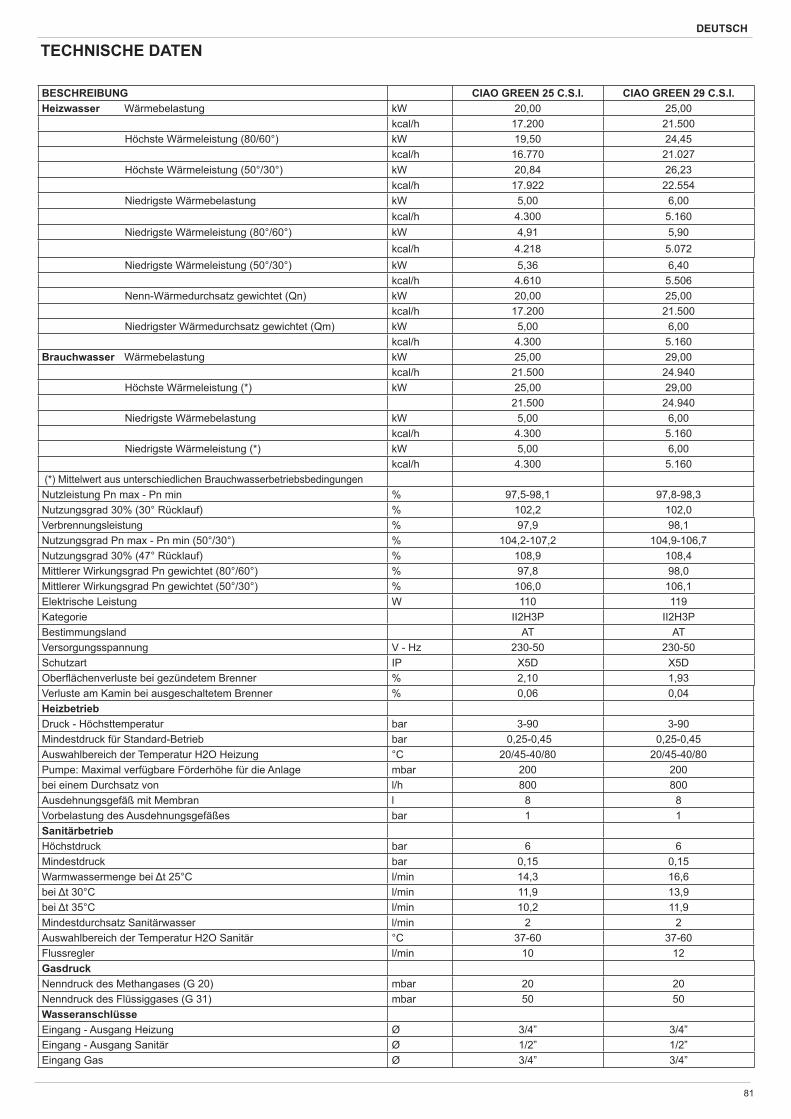
DEUTSCH
81
BESCHREIBUNG CIAO GREEN 25 C.S.I. CIAO GREEN 29 C.S.I.Heizwasser Wärmebelastung kW 20,00 25,00
kcal/h 17.200 21.500Höchste Wärmeleistung (80/60°) kW 19,50 24,45
kcal/h 16.770 21.027Höchste Wärmeleistung (50°/30°) kW 20,84 26,23
kcal/h 17.922 22.554Niedrigste Wärmebelastung kW 5,00 6,00
kcal/h 4.300 5.160Niedrigste Wärmeleistung (80°/60°) kW 4,91 5,90
kcal/h 4.218 5.072Niedrigste Wärmeleistung (50°/30°) kW 5,36 6,40
kcal/h 4.610 5.506Nenn-Wärmedurchsatz gewichtet (Qn) kW 20,00 25,00
kcal/h 17.200 21.500Niedrigster Wärmedurchsatz gewichtet (Qm) kW 5,00 6,00
kcal/h 4.300 5.160Brauchwasser Wärmebelastung kW 25,00 29,00
kcal/h 21.500 24.940Höchste Wärmeleistung (*) kW 25,00 29,00
21.500 24.940Niedrigste Wärmebelastung kW 5,00 6,00
kcal/h 4.300 5.160Niedrigste Wärmeleistung (*) kW 5,00 6,00
kcal/h 4.300 5.160 (*) Mittelwert aus unterschiedlichen BrauchwasserbetriebsbedingungenNutzleistung Pn max - Pn min % 97,5-98,1 97,8-98,3Nutzungsgrad 30% (30° Rücklauf) % 102,2 102,0Verbrennungsleistung % 97,9 98,1Nutzungsgrad Pn max - Pn min (50°/30°) % 104,2-107,2 104,9-106,7Nutzungsgrad 30% (47° Rücklauf) % 108,9 108,4Mittlerer Wirkungsgrad Pn gewichtet (80°/60°) % 97,8 98,0Mittlerer Wirkungsgrad Pn gewichtet (50°/30°) % 106,0 106,1Elektrische Leistung W 110 119Kategorie II2H3P II2H3PBestimmungsland AT ATVersorgungsspannung V - Hz 230-50 230-50Schutzart IP X5D X5DOber ächenverluste bei gezündetem Brenner % 2,10 1,93 Verluste am Kamin bei ausgeschaltetem Brenner % 0,06 0,04HeizbetriebDruck - Höchsttemperatur bar 3-90 3-90Mindestdruck für Standard-Betrieb bar 0,25-0,45 0,25-0,45Auswahlbereich der Temperatur H2O Heizung °C 20/45-40/80 20/45-40/80 Pumpe: Maximal verfügbare Förderhöhe für die Anlage mbar 200 200bei einem Durchsatz von l/h 800 800Ausdehnungsgefäß mit Membran l 8 8Vorbelastung des Ausdehnungsgefäßes bar 1 1SanitärbetriebHöchstdruck bar 6 6Mindestdruck bar 0,15 0,15Warmwassermenge bei t 25°C l/min 14,3 16,6bei t 30°C l/min 11,9 13,9bei t 35°C l/min 10,2 11,9Mindestdurchsatz Sanitärwasser l/min 2 2Auswahlbereich der Temperatur H2O Sanitär °C 37-60 37-60Flussregler l/min 10 12GasdruckNenndruck des Methangases (G 20) mbar 20 20Nenndruck des Flüssiggases (G 31) mbar 50 50WasseranschlüsseEingang - Ausgang Heizung Ø 3/4” 3/4”Eingang - Ausgang Sanitär Ø 1/2” 1/2”Eingang Gas Ø 3/4” 3/4”
TECHNISCHE DATEN
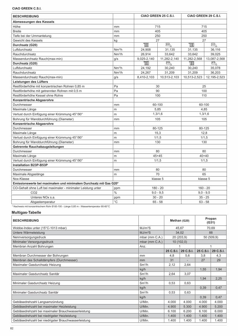
CIAO GREEN C.S.I.
82
BESCHREIBUNG CIAO GREEN 25 C.S.I. CIAO GREEN 29 C.S.I.
Abmessungen des KesselsHöhe mm 715 715Breite mm 405 405Tiefe bei der Ummantelung mm 250 250Gewicht des Kessels kg 27 27Durchsatz (G20)Luftdurchsatz Nm3/h 24,908 31,135 31,135 36,116Rauchdurchsatz Nm3/h 26,914 33,642 33,642 39,025Massendurchsatz Rauch(max-min) g/s 9,025-2,140 11,282-2,140 11,282-2,568 13,087-2,568Durchsatz (G20)Luftdurchsatz Nm3/h 24,192 30,240 30,240 35,078Rauchdurchsatz Nm3/h 24,267 31,209 31,209 36,203Massendurchsatz Rauch(max-min) g/s 8,410-2,103 10,513-2,103 10,513-2,523 12,195-2,523Leistungen des LüftersRestförderhöhe mit konzentrischen Rohren 0,85 m Pa 30 25Restförderhöhe mit getrennten Rohren mit 0,5 m Pa 90 100Restförderhöhe Kessel ohne Rohre Pa 100 110Konzentrische AbgasrohreDurchmesser mm 60-100 60-100Maximale Länge m 5,85 4,85Verlust durch Einfügung einer Krümmung 45°/90° m 1,3/1,6 1,3/1,6Bohrung für Wanddurchführung (Diameter) mm 105 105Konzentrische AbgasrohreDurchmesser mm 80-125 80-125Maximale Länge m 15,3 12,8Verlust durch Einfügung einer Krümmung 45°/90° m 1/1,5 1/1,5Bohrung für Wanddurchführung (Diameter) mm 130 130Getrennte RauchabzugsleitungenDurchmesser mm 80 80Maximale Länge m 45+45 40+40Verlust durch Einfügung einer Krümmung 45°/90° m 1/1,5 1/1,5Installation B23P-B53PDurchmesser mm 80 80Maximale Abgaslänge m 70 65Nox-Klasse klasse 5 klasse 5Emissionswerte bei maximalem und minimalem Durchsatz mit Gas G20*CO-Gehalt ohne Luft bei maximaler - minimaler Leistung unter ppm 180 - 20 160 - 20 CO2 % 9,0 - 9,5 9,0 - 9,5 Unteres NOx s.a. ppm 30 - 20 35 - 25 Abgastemperatur °C 65 - 58 63 - 58
* Nachweis mit konzentrischem Rohr Ø 60-100 - Länge 0,85 m - Wassertemperatur 80-60°C
BESCHREIBUNG Methan (G20) Propan (G31)
Wobbe-Index unter (15°C-1013 mbar) MJ/m3S 45,67 70,69Untere Wärmeleistung MJ/m3S 34,02 88Nennversorgungsdruck mbar (mm C.A.) 20 (203,9) 50 (509,9)Minimaler Versorgungsdruck mbar (mm C.A.) 10 (102,0)Membran Anzahl Bohrungen Anz. 1 1
25 C.S.I. 29 C.S.I. 25 C.S.I. 29 C.S.I.Membran Durchmesser der Bohrungen mm 4,8 5,6 3,8 4,3Membran des Schalldämpfers (Durchmesser) mm 31 - 27 29Maximaler Gasdurchsatz Heizung Sm3/h 2,12 2,64
kg/h 1,55 1,94Maximaler Gasdurchsatz Sanitär Sm3/h 2,64 3,07
kg/h 1,94 2,25Minimaler Gasdurchsatz Heizung Sm3/h 0,53 0,63
kg/h 0,39 0,47Minimaler Gasdurchsatz Sanitär Sm3/h 0,53 0,63
kg/h 0,39 0,47Gebläsedrehzahl Langsamzündung U/Min. 4.000 4.000 4.000 4.000Gebläsedrehzahl bei maximaler Heizleistung U/Min. 4.900 5.300 4.900 5.200Gebläsedrehzahl bei maximaler Brauchwasserleistung U/Min. 6.100 6.200 6.100 6.000Gebläsedrehzahl bei niedrigster Heizleistung U/Min. 1.400 1.400 1.400 1.400Gebläsedrehzahl bei niedrigster Brauchwasserleistung U/Min. 1.400 1.400 1.400 1.400
Multigas-Tabelle
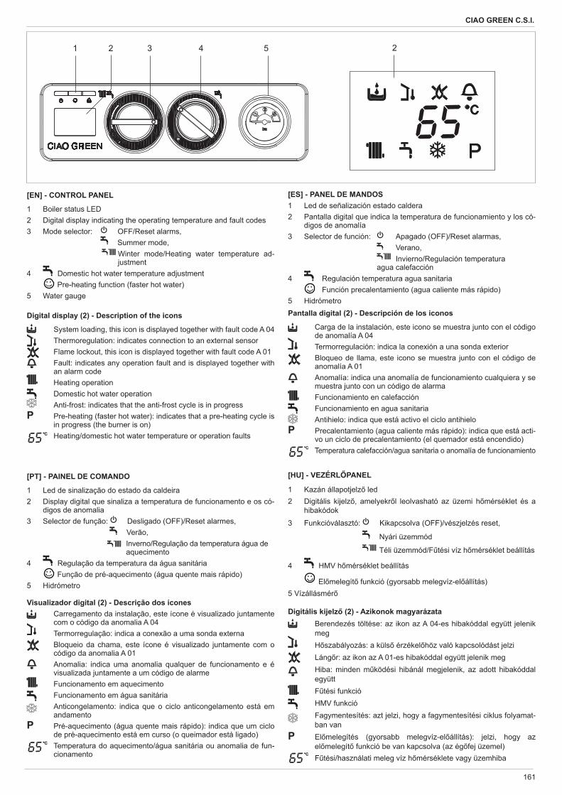
161
CIAO GREEN C.S.I.
1 2 3 4 5
��
2
[EN] - CONTROL PANEL
1 Boiler status LED2 Digital display indicating the operating temperature and fault codes3 Mode selector: OFF/Reset alarms,
Summer mode, Winter mode/Heating water temperature ad-justment
4 Domestic hot water temperature adjustment Pre-heating function (faster hot water)5 Water gauge
Digital display (2) - Description of the icons
System loading, this icon is displayed together with fault code A 04 Thermoregulation: indicates connection to an external sensor Flame lockout, this icon is displayed together with fault code A 01
Fault: indicates any operation fault and is displayed together with an alarm code
Heating operation Domestic hot water operation Anti-frost: indicates that the anti-frost cycle is in progress
P Pre-heating (faster hot water): indicates that a pre-heating cycle is in progress (the burner is on)
�� Heating/domestic hot water temperature or operation faults
[PT] - PAINEL DE COMANDO
1 Led de sinalização do estado da caldeira2 Display digital que sinaliza a temperatura de funcionamento e os có-
digos de anomalia3 Selector de função: Desligado (OFF)/Reset alarmes, Verão,
Inverno/Regulação da temperatura água de aquecimento
4 Regulação da temperatura da água sanitária Função de pré-aquecimento (água quente mais rápido)5 Hidrómetro
Visualizador digital (2) - Descrição dos ícones Carregamento da instalação, este ícone é visualizado juntamente
com o código da anomalia A 04 Termorregulação: indica a conexão a uma sonda externa Bloqueio da chama, este ícone é visualizado juntamente com o
código da anomalia A 01 Anomalia: indica uma anomalia qualquer de funcionamento e é
visualizada juntamente a um código de alarme Funcionamento em aquecimento Funcionamento em água sanitária Anticongelamento: indica que o ciclo anticongelamento está em
andamentoP Pré-aquecimento (água quente mais rápido): indica que um ciclo
de pré-aquecimento está em curso (o queimador está ligado)
�� Temperatura do aquecimento/água sanitária ou anomalia de fun-cionamento
[ES] - PANEL DE MANDOS1 Led de señalización estado caldera2 Pantalla digital que indica la temperatura de funcionamiento y los có-
digos de anomalía3 Selector de función: Apagado (OFF)/Reset alarmas, Verano, Invierno/Regulación temperatura
agua calefacción4 Regulación temperatura agua sanitaria Función precalentamiento (agua caliente más rápido)5 HidrómetroPantalla digital (2) - Descripción de los iconos
Carga de la instalación, este icono se muestra junto con el código de anomalía A 04
Termorregulación: indica la conexión a una sonda exterior Bloqueo de llama, este icono se muestra junto con el código de
anomalía A 01 Anomalía: indica una anomalía de funcionamiento cualquiera y se
muestra junto con un código de alarma Funcionamiento en calefacción Funcionamiento en agua sanitaria Antihielo: indica que está activo el ciclo antihielo
P Precalentamiento (agua caliente más rápido): indica que está acti-vo un ciclo de precalentamiento (el quemador está encendido)
�� Temperatura calefacción/agua sanitaria o anomalía de funcionamiento
[HU] - VEZÉRL PANEL
1 Kazán állapotjelz led2 Digitális kijelz , amelyekr l leolvasható az üzemi h mérséklet és a
hibakódok
3 Funkcióválasztó: Kikapcsolva (OFF)/vészjelzés reset,
Nyári üzemmód
Téli üzemmód/F tési víz h mérséklet beállítás
4 HMV h mérséklet beállítás
El melegít funkció (gyorsabb melegvíz-el állítás)5 Vízállásmér
Digitális kijelz (2) - Azikonok magyarázata Berendezés töltése: az ikon az A 04-es hibakóddal együtt jelenik
meg H szabályozás: a küls érzékel höz való kapcsolódást jelzi Láng r: az ikon az A 01-es hibakóddal együtt jelenik meg
Hiba: minden m ködési hibánál megjelenik, az adott hibakóddal együtt
F tési funkció HMV funkció Fagymentesítés: azt jelzi, hogy a fagymentesítési ciklus folyamat-
ban vanP El melegítés (gyorsabb melegvíz-el állítás): jelzi, hogy az
el melegít funkció be van kapcsolva (az ég fej üzemel)
�� F tési/használati meleg víz h mérséklete vagy üzemhiba
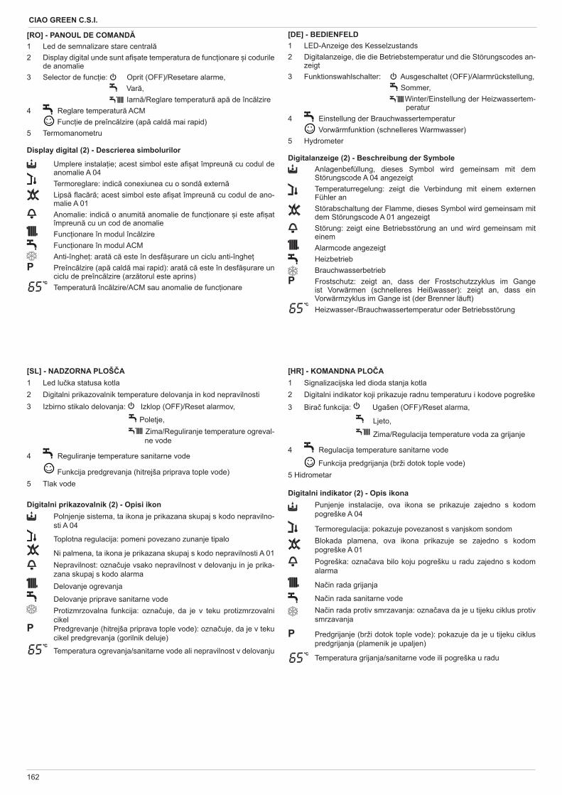
162
CIAO GREEN C.S.I.
[RO] - PANOUL DE COMAND1 Led de semnalizare stare central2 Display digital unde sunt a ate temperatura de func ionare i codurile
de anomalie3 Selector de func ie: Oprit (OFF)/Resetare alarme, Var , Iarn /Reglare temperatur ap de înc lzire4 Reglare temperatur ACM Func ie de preînc lzire (ap cald mai rapid)5 Termomanometru
Display digital (2) - Descrierea simbolurilor
Umplere instala ie; acest simbol este a at împreun cu codul de anomalie A 04
Termoreglare: indic conexiunea cu o sond extern Lips ac r ; acest simbol este a at împreun cu codul de ano-
malie A 01 Anomalie: indic o anumit anomalie de func ionare i este a at
împreun cu un cod de anomalie Func ionare în modul înc lzire Func ionare în modul ACM Anti-înghe : arat c este în desf urare un ciclu anti-înghe
P Preînc lzire (ap cald mai rapid): arat c este în desf urare un ciclu de preînc lzire (arz torul este aprins)
�� Temperatur înc lzire/ACM sau anomalie de func ionare
[DE] - BEDIENFELD1 LED-Anzeige des Kesselzustands2 Digitalanzeige, die die Betriebstemperatur und die Störungscodes an-
zeigt3 Funktionswahlschalter: Ausgeschaltet (OFF)/Alarmrückstellung, Sommer,
Winter/Einstellung der Heizwassertem-peratur
4 Einstellung der Brauchwassertemperatur Vorwärmfunktion (schnelleres Warmwasser)5 Hydrometer
Digitalanzeige (2) - Beschreibung der Symbole Anlagenbefüllung, dieses Symbol wird gemeinsam mit dem
Störungscode A 04 angezeigt Temperaturregelung: zeigt die Verbindung mit einem externen
Fühler an Störabschaltung der Flamme, dieses Symbol wird gemeinsam mit
dem Störungscode A 01 angezeigt Störung: zeigt eine Betriebsstörung an und wird gemeinsam mit
einem Alarmcode angezeigt Heizbetrieb Brauchwasserbetrieb
P Frostschutz: zeigt an, dass der Frostschutzzyklus im Gange ist Vorwärmen (schnelleres Heißwasser): zeigt an, dass ein Vorwärmzyklus im Gange ist (der Brenner läuft)
�� Heizwasser-/Brauchwassertemperatur oder Betriebsstörung
[SL] - NADZORNA PLOŠ A1 Led lu ka statusa kotla2 Digitalni prikazovalnik temperature delovanja in kod nepravilnosti3 Izbirno stikalo delovanja: Izklop (OFF)/Reset alarmov,
Poletje, Zima/Reguliranje temperature ogreval-ne vode
4 Reguliranje temperature sanitarne vode
Funkcija predgrevanja (hitrejša priprava tople vode)5 Tlak vode
Digitalni prikazovalnik (2) - Opisi ikon Polnjenje sistema, ta ikona je prikazana skupaj s kodo nepravilno-
sti A 04
Toplotna regulacija: pomeni povezano zunanje tipalo
Ni palmena, ta ikona je prikazana skupaj s kodo nepravilnosti A 01 Nepravilnost: ozna uje vsako nepravilnost v delovanju in je prika-
zana skupaj s kodo alarma Delovanje ogrevanja
Delovanje priprave sanitarne vode Protizmrzovalna funkcija: ozna uje, da je v teku protizmrzovalni
cikelP Predgrevanje (hitrejša priprava tople vode): ozna uje, da je v teku
cikel predgrevanja (gorilnik deluje)
�� Temperatura ogrevanja/sanitarne vode ali nepravilnost v delovanju
[HR] - KOMANDNA PLO A1 Signalizacijska led dioda stanja kotla2 Digitalni indikator koji prikazuje radnu temperaturu i kodove pogreške
3 Bira funkcija: Ugašen (OFF)/Reset alarma,
Ljeto,
Zima/Regulacija temperature voda za grijanje
4 Regulacija temperature sanitarne vode
Funkcija predgrijanja (brži dotok tople vode)5 Hidrometar
Digitalni indikator (2) - Opis ikona Punjenje instalacije, ova ikona se prikazuje zajedno s kodom
pogreške A 04
Termoregulacija: pokazuje povezanost s vanjskom sondom Blokada plamena, ova ikona prikazuje se zajedno s kodom
pogreške A 01 Pogreška: ozna ava bilo koju pogrešku u radu zajedno s kodom
alarma
Na in rada grijanja
Na in rada sanitarne vode Na in rada protiv smrzavanja: ozna ava da je u tijeku ciklus protiv
smrzavanja
P Predgrijanje (brži dotok tople vode): pokazuje da je u tijeku ciklus predgrijanja (plamenik je upaljen)
�� Temperatura grijanja/sanitarne vode ili pogreška u radu
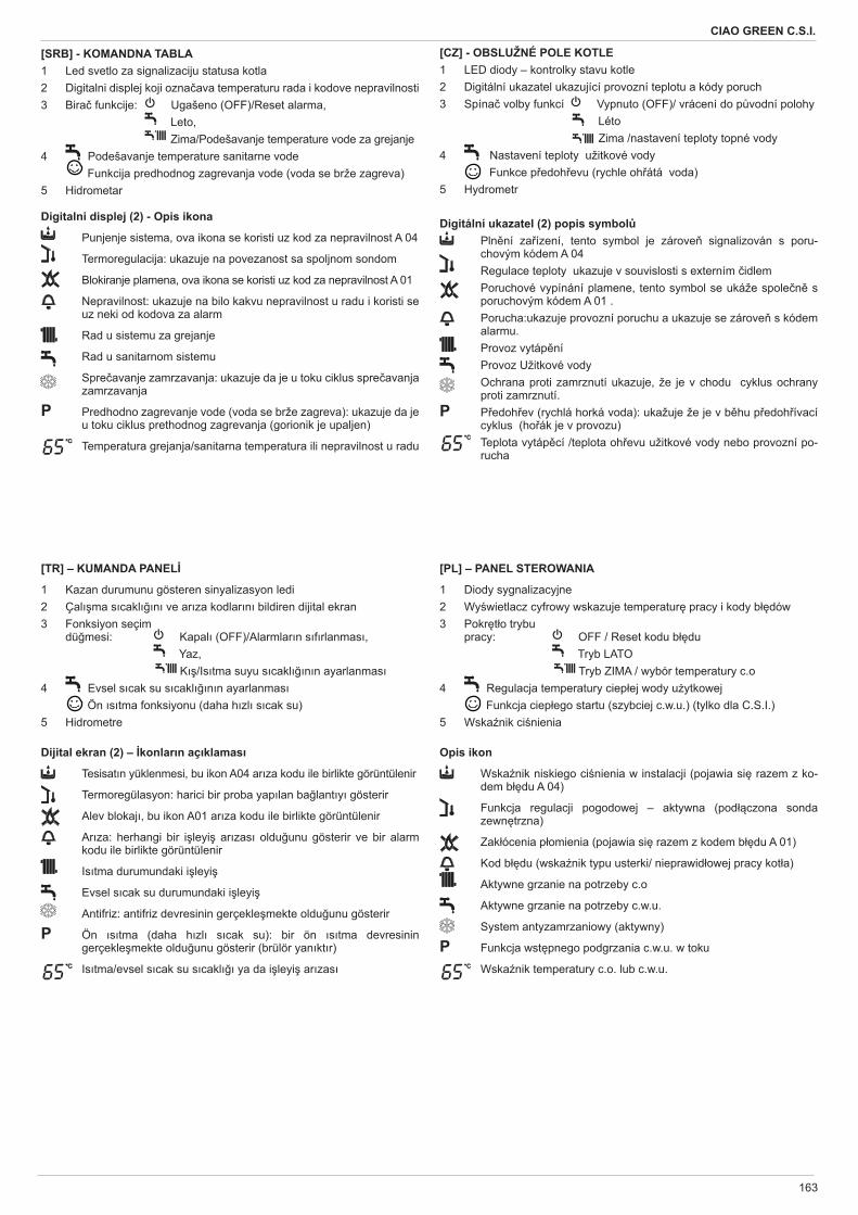
163
CIAO GREEN C.S.I.
[SRB] - KOMANDNA TABLA1 Led svetlo za signalizaciju statusa kotla2 Digitalni displej koji ozna ava temperaturu rada i kodove nepravilnosti3 Bira funkcije: Ugašeno (OFF)/Reset alarma, Leto, Zima/Podešavanje temperature vode za grejanje4 Podešavanje temperature sanitarne vode Funkcija predhodnog zagrevanja vode (voda se brže zagreva)5 Hidrometar
Digitalni displej (2) - Opis ikona
Punjenje sistema, ova ikona se koristi uz kod za nepravilnost A 04
Termoregulacija: ukazuje na povezanost sa spoljnom sondom
Blokiranje plamena, ova ikona se koristi uz kod za nepravilnost A 01
Nepravilnost: ukazuje na bilo kakvu nepravilnost u radu i koristi se uz neki od kodova za alarm
Rad u sistemu za grejanje
Rad u sanitarnom sistemu
Spre avanje zamrzavanja: ukazuje da je u toku ciklus spre avanja zamrzavanja
P Predhodno zagrevanje vode (voda se brže zagreva): ukazuje da je u toku ciklus prethodnog zagrevanja (gorionik je upaljen)
�� Temperatura grejanja/sanitarna temperatura ili nepravilnost u radu
[CZ] - OBSLUŽNÉ POLE KOTLE 1 LED diody – kontrolky stavu kotle2 Digitální ukazatel ukazující provozní teplotu a kódy poruch3 Spína volby funkcí Vypnuto (OFF)/ vrácení do p vodní polohy Léto Zima /nastavení teploty topné vody4 Nastavení teploty užitkové vody Funkce p edoh evu (rychle oh átá voda)5 Hydrometr
Digitální ukazatel (2) popis symbol Pln ní za ízení, tento symbol je zárove signalizován s poru-
chovým kódem A 04 Regulace teploty ukazuje v souvislosti s externím idlem Poruchové vypínání plamene, tento symbol se ukáže spole n s
poruchovým kódem A 01 . Porucha:ukazuje provozní poruchu a ukazuje se zárove s kódem
alarmu. Provoz vytáp ní Provoz Užitkové vody Ochrana proti zamrznutí ukazuje, že je v chodu cyklus ochrany
proti zamrznutí.P P edoh ev (rychlá horká voda): ukažuje že je v b hu p edoh ívací
cyklus (ho ák je v provozu)
�� Teplota vytáp cí /teplota oh evu užitkové vody nebo provozní po-rucha
[TR] – KUMANDA PANEL
1 Kazan durumunu gösteren sinyalizasyon ledi2 Çal ma s cakl n ve ar za kodlar n bildiren dijital ekran3 Fonksiyon seçim
dü mesi: Kapal (OFF)/Alarmlar n s f rlanmas , Yaz,
K /Is tma suyu s cakl n n ayarlanmas4 Evsel s cak su s cakl n n ayarlanmas Ön s tma fonksiyonu (daha h zl s cak su)5 Hidrometre
Dijital ekran (2) – konlar n aç klamas
Tesisat n yüklenmesi, bu ikon A04 ar za kodu ile birlikte görüntülenir
Termoregülasyon: harici bir proba yap lan ba lant y gösterir
Alev blokaj , bu ikon A01 ar za kodu ile birlikte görüntülenir
Ar za: herhangi bir i leyi ar zas oldu unu gösterir ve bir alarm kodu ile birlikte görüntülenir
Is tma durumundaki i leyi
Evsel s cak su durumundaki i leyi
Antifriz: antifriz devresinin gerçekle mekte oldu unu gösterir
P Ön s tma (daha h zl s cak su): bir ön s tma devresinin gerçekle mekte oldu unu gösterir (brülör yan kt r)
�� Is tma/evsel s cak su s cakl ya da i leyi ar zas
[PL] – PANEL STEROWANIA
1 Diody sygnalizacyjne2 Wy wietlacz cyfrowy wskazuje temperatur pracy i kody b dów3 Pokr t o trybu
pracy: OFF / Reset kodu b du Tryb LATO
Tryb ZIMA / wybór temperatury c.o4 Regulacja temperatury ciep ej wody u ytkowej Funkcja ciep ego startu (szybciej c.w.u.) (tylko dla C.S.I.)5 Wska nik ci nienia
Opis ikon
Wska nik niskiego ci nienia w instalacji (pojawia si razem z ko-dem b du A 04)
Funkcja regulacji pogodowej – aktywna (pod czona sonda zewn trzna)
Zak ócenia p omienia (pojawia si razem z kodem b du A 01)
Kod b du (wska nik typu usterki/ nieprawid owej pracy kot a)
Aktywne grzanie na potrzeby c.o
Aktywne grzanie na potrzeby c.w.u.
System antyzamrzaniowy (aktywny)
P Funkcja wst pnego podgrzania c.w.u. w toku
�� Wska nik temperatury c.o. lub c.w.u.
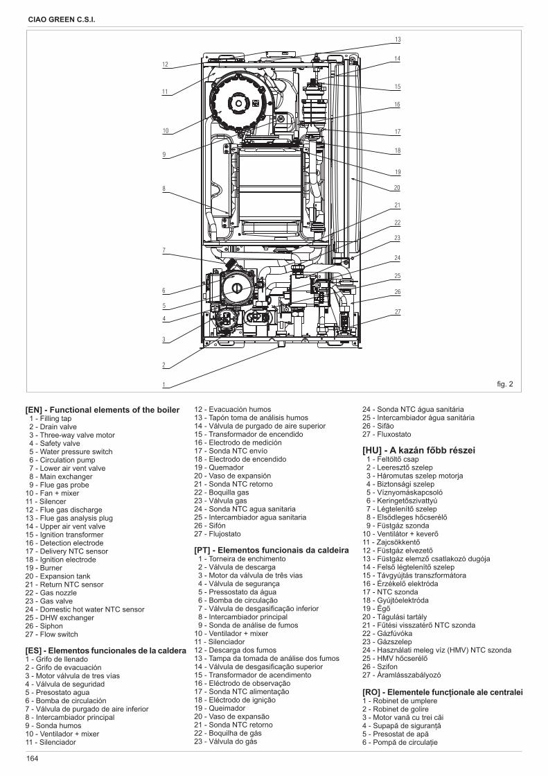
164
CIAO GREEN C.S.I.
g. 2
12 - Evacuación humos13 - Tapón toma de análisis humos14 - Válvula de purgado de aire superior15 - Transformador de encendido16 - Electrodo de medición17 - Sonda NTC envío18 - Electrodo de encendido19 - Quemador20 - Vaso de expansión21 - Sonda NTC retorno22 - Boquilla gas23 - Válvula gas 24 - Sonda NTC agua sanitaria25 - Intercambiador agua sanitaria26 - Sifón27 - Flujostato
[PT] - Elementos funcionais da caldeira 1 - Torneira de enchimento 2 - Válvula de descarga 3 - Motor da válvula de três vias 4 - Válvula de segurança 5 - Pressostato da água 6 - Bomba de circulação 7 - Válvula de desgasi cação inferior 8 - Intercambiador principal 9 - Sonda de análise de fumos10 - Ventilador + mixer11 - Silenciador12 - Descarga dos fumos13 - Tampa da tomada de análise dos fumos14 - Válvula de desgasi cação superior15 - Transformador de acendimento16 - Eléctrodo de observação17 - Sonda NTC alimentação 18 - Eléctrodo de ignição19 - Queimador20 - Vaso de expansão21 - Sonda NTC retorno22 - Boquilha de gás23 - Válvula do gás
[EN] - Functional elements of the boiler 1 - Filling tap 2 - Drain valve 3 - Three-way valve motor 4 - Safety valve 5 - Water pressure switch 6 - Circulation pump 7 - Lower air vent valve 8 - Main exchanger 9 - Flue gas probe10 - Fan + mixer11 - Silencer12 - Flue gas discharge13 - Flue gas analysis plug14 - Upper air vent valve15 - Ignition transformer16 - Detection electrode17 - Delivery NTC sensor18 - Ignition electrode19 - Burner20 - Expansion tank21 - Return NTC sensor22 - Gas nozzle23 - Gas valve 24 - Domestic hot water NTC sensor25 - DHW exchanger26 - Siphon27 - Flow switch
[ES] - Elementos funcionales de la caldera 1 - Grifo de llenado2 - Grifo de evacuación 3 - Motor válvula de tres vías 4 - Válvula de seguridad 5 - Presostato agua6 - Bomba de circulación 7 - Válvula de purgado de aire inferior8 - Intercambiador principal9 - Sonda humos10 - Ventilador + mixer11 - Silenciador
24 - Sonda NTC água sanitária25 - Intercambiador água sanitária26 - Sifão27 - Fluxostato
[HU] - A kazán f bb részei 1 - Feltölt csap 2 - Leereszt szelep 3 - Háromutas szelep motorja 4 - Biztonsági szelep 5 - Víznyomáskapcsoló 6 - Keringet szivattyú 7 - Légtelenít szelep 8 - Els dleges h cserél 9 - Füstgáz szonda10 - Ventilátor + kever11 - Zajcsökkent12 - Füstgáz elvezet13 - Füstgáz elemz csatlakozó dugója14 - Fels légtelenít szelep15 - Távgyújtás transzformátora16 - Érzékel elektróda17 - NTC szonda18 - Gyújtóelektróda19 - Ég20 - Tágulási tartály21 - F tési visszatér NTC szonda22 - Gázfúvóka23 - Gázszelep 24 - Használati meleg víz (HMV) NTC szonda25 - HMV h cserél26 - Szifon27 - Áramlásszabályozó
[RO] - Elementele func ionale ale centralei1 - Robinet de umplere2 - Robinet de golire3 - Motor van cu trei c i4 - Supap de siguran5 - Presostat de ap6 - Pomp de circula ie
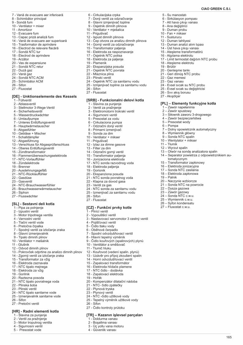
165
CIAO GREEN C.S.I.
7 - Van de evacuare aer inferioar8 - Schimb tor principal9 - Sond fum10 - Ventilator + mixer11 - Amortizor12 - Evacuare fum13 - Capac priz analiz fum14 - Van de evacuare aer superioar15 - Trasformator de aprindere16 - Electrod de relevare ac r17 - Sond NTC tur 18 - Electrod de aprindere19 - Arz tor20 - Vas de expansiune21 - Sond NTC retur22 - Duz gaz23 - Van gaz24 - Sond NTC ACM25 - Schimb tor ACM26 - Sifon27 - Fluxostat
[DE] - Unktionselemente des Kessels 1 - Füllventil 2 - Ablassventil 3 - Stellmotor 3-Wege-Ventil 4 - Sicherheitsventil 5 - Wasserdruckwächter 6 - Umlaufpumpe 7 - Unteres Entlüftungsventil 8 - Hauptwärmetauscher 9 - Abgasfühler10 - Gebläse + Mischer11 - Schalldämpfer12 - Abgasführung13 - Verschluss für Abgasprüfanschluss14 - Oberes Entlüftungsventil15 - Zündtransformator16 - Flammenüberwachungselektrode17 - NTC-Vorlauffühler18 - Zündelektrode19 - Brenner20 - Ausdehnungsgefäß21 - NTC-Rücklauffühler22 - Gasdüse23 - Gasventil 24 - NTC-Brauchwasserfühler25 - Brauchwasserwärmetauscher26 - Siphon27 - Flusswächter
[SL] - Sestavni deli kotla 1 - Pipa za polnjenje 2 - Izpustni ventil 3 - Motor tripotnega ventila 4 - Varnostni ventil 5 - Tla ni ventil vode 6 - Preto na rpalka 7 - Spodnji ventil za izlo anje zraka 8 - Glavni izmenjevalnik 9 - Tipalo dimnih plinov10 - Ventilator + mešalnik11 - Glušnik12 - Odvod dimnih plinov13 - Pokrov ek odprtine za analizo dimnih plinov14 - Zgornji ventil za izlo anje zraka15 - Transformator za vžig16 - Elektroda zaznavala17 - NTC tipalo mejnega 18 - Elektroda za vžig19 - Gorilnik20 - Raztezna posoda21 - NTC tipalo povratnega voda22 - Plinska šoba23 - Plinski ventil 24 - NTC tipalo sanitarne vode25 - Izmenjevalnik sanitarne vode26 - Sifon27 - Preto ni ventil
[HR] - Radni elementi kotla 1 - Slavina za punjenje 2 - Ventil za pražnjenje 3 - Motor troputnog ventila 4 - Sigurnosni ventil 5 - Presostat vode
6 - Cirkulacijska crpka 7 - Donji ventil za odzra ivanje 8 - Glavni izmjenjiva topline 9 - Osjetnik dimnih plinova10 - Ventilator + mješalica11 - Prigušiva12 - Ispust dimnih plinova13 - ep otvora za analizu dimnih plinova14 - Gornji ventil za odzra ivanje15 - Transformator paljenja16 - Elektroda za raspoznavanje17 - Osjetnik NTC potisa18 - Elektroda za paljenje19 - Plamenik20 - Ekspanzijska posuda21 - Osjetnik NTC povrata22 - Mlaznica plina23 - Plinski ventil 24 - Osjetnik NTC za sanitarnu vodu25 - Izmjenjiva topline za sanitarnu vodu26 - Sifon27 - Flusostat
[SRB] - Funkcionalni delovi kotla 1 - Slavina za punjenje 2 - Ventil za pražnjenje 3 - Elektromotorni trokraki ventil 4 - Sigurnosni ventil 5 - Presostat za vodu 6 - Cirkulaciona pumpa 7 - Odzra ni donji ventil 8 - Primarni izmenjiva 9 - Sonda za dim10 - Ventilator + mikser11 - Prigušiva12 - Izlaz za dimne gasove13 - Filter za dim14 - Odzra ni gornji ventil15 - Transformator paljenja16 - Jonizaciona elektroda17 - NTC sonda razvodnog voda 18 - Elektroda paljenja19 - Gorionik20 - Ekspanziona posuda21 - NTC sonda povratnog voda22 - Klapna za dovod gasa23 - Ventil za gas 24 - NTC sonda za sanitarnu vodu25 - Izmenjiva za sanitarnu vodu26 - Sifon27 - Flusostat
[CZ] - Funk ní prvky kotle 1 - Plnící ventil2 - Vypoušt cí ventil3 - Nastavovací servomotor 3 cestný ventil4 - Pojiš ovací ventil5 - idlo tlaku vody6 - Ob hové erpadlo7 - Spodní odvzduš ovací ventil8 - Hlavní tepelný vým ník9 - idlo kou ových (spalinových) plyn10 - Ventilátor a sm šova11 - Tlumi hluku12 - Kou ovod (vedení spalin. plyn )13 - Uzáv r pro p ípoj zkoušení spalin14 - Horní odvzduš ovací ventil15 - Zapalovací transformátor16 - Elektroda hlída e plamene17 - NTC idlo - dodávka18 - Zapalovací elektroda19 - Ho ák20 - Kompenzátor dilata ní nádoba21 - NTC- idlo zpáte ky22 - Plynová tryska23 - Plynový ventil24 - NTC - idlo užitkové vody25 - Tepelný vým ník užitkové vody26 - Sifon27 - idlo kontroly pr toku
[TR] – Kazan n i levsel parçalar 1 - Doldurma vanas 2 - Bo altma vanas 3 - Üç yollu vana motoru 4 - Güvenlik vanas
5 - Su manostat 6 - Sirkülasyon pompas 7 - Alt hava ç k vanas 8 - Ana de i tirici 9 - Duman probu10 - Fan + mikser11 - Susturucu12 - Duman tahliyesi13 - Duman analizi al m t pas14 - Üst hava ç k vanas15 - Ate leme transformatörü16 - Alg lama elektrotu17 - Limit termostat da t m NTC probu18 - Ate leme elektrotu19 - Brülör20 - Genle me tank21 - Geri dönü NTC probu22 - Gaz memesi23 - Gaz vanas24 - Evsel s cak su NTC probu25 - Evsel s cak su de i tiricisi26 - S v ak borusu27 - Ak ölçer
[PL] – Elementy funkcyjne kot a 1 – Zawór nape aninia 2 – Zawór spustowy 3 – Si ownik zaworu 3-drogowego 4 – Zawór bezpiecze twa 5 – Presostat wody 6 – Pompa 7 – Dolny opowietrznik automatyczny 8 – Wymiennik g ówny 9 – Sonda NTC spalin10 – Wentylator + mikser11 – T umik12 – Wyrzut spalin13 – Otwór na sond analizatora spalin14 – Separator powietrza z odpowietrznikiem au-
tomatycznym15 – Transformator zap onowy16 – Elektroda jonizacyjna17 – Sonda NTC zasilania18 – Elektroda zap onowa19 – Palnik20 – Naczynie wzbiorcze21 – Sonda NTC na powrocie22 – Dysza gazowa23 – Zawór gazowy24 – Sonda NTC c.w.u.25 – Wymiennik c.w.u.26 – Syfon kondensatu27 – Flusostat c.w.u.
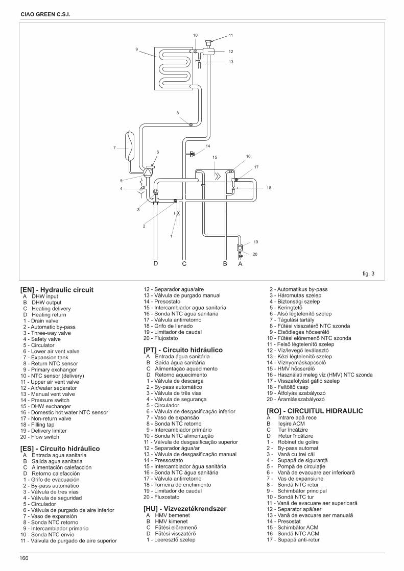
166
CIAO GREEN C.S.I.
g. 3
D C B A
8
9
614
15
3
1
16
12
11
2
17
19
20
4
5
7
10
13
18
[EN] - Hydraulic circuit A DHW input B DHW output C Heating delivery D Heating return 1 - Drain valve 2 - Automatic by-pass 3 - Three-way valve 4 - Safety valve 5 - Circulator 6 - Lower air vent valve 7 - Expansion tank 8 - Return NTC sensor 9 - Primary exchanger 10 - NTC sensor (delivery)11 - Upper air vent valve12 - Air/water separator13 - Manual vent valve14 - Pressure switch15 - DHW exchanger16 - Domestic hot water NTC sensor17 - Non-return valve 18 - Filling tap19 - Delivery limiter20 - Flow switch
[ES] - Circuito hidráulico A Entrada agua sanitaria B Salida agua sanitaria C Alimentación calefacción D Retorno calefacción 1 - Grifo de evacuación 2 - By-pass automático 3 - Válvula de tres vías 4 - Válvula de seguridad 5 - Circulador 6 - Válvula de purgado de aire inferior 7 - Vaso de expansión 8 - Sonda NTC retorno 9 - Intercambiador primario 10 - Sonda NTC envío11 - Válvula de purgado de aire superior
12 - Separador agua/aire13 - Válvula de purgado manual14 - Presostato15 - Intercambiador agua sanitaria16 - Sonda NTC agua sanitaria17 - Válvula antirretorno 18 - Grifo de llenado19 - Limitador de caudal20 - Flujostato
[PT] - Circuito hidráulico A Entrada água sanitária B Saída água sanitária C Alimentação aquecimento D Retorno aquecimento 1 - Válvula de descarga 2 - By-pass automático 3 - Válvula de três vias 4 - Válvula de segurança 5 - Circulador 6 - Válvula de desgasi cação inferior 7 - Vaso de expansão 8 - Sonda NTC retorno 9 - Intercambiador primário 10 - Sonda NTC alimentação11 - Válvula de desgasi cação superior12 - Separador água/ar13 - Válvula de desgasi cação manual14 - Pressostato15 - Intercambiador água sanitária16 - Sonda NTC água sanitária17 - Válvula antirretorno 18 - Torneira de enchimento19 - Limitador de caudal20 - Fluxostato
[HU] - Vízvezetékrendszer A HMV bemenet B HMV kimenet C F tési el remen D F tési visszatér 1 - Leereszt szelep
2 - Automatikus by-pass 3 - Háromutas szelep 4 - Biztonsági szelep 5 - Keringtet 6 - Alsó légtelenít szelep 7 - Tágulási tartály 8 - F tési visszatér NTC szonda 9 - Els dleges h cserél 10 - F tési el remen NTC szonda11 - Fels légtelenít szelep12 - Víz/leveg leválasztó13 - Kézi légtelenít szelep14 - Víznyomáskapcsoló15 - HMV h cserél16 - Használati meleg víz (HMV) NTC szonda17 - Visszafolyást gátló szelep 18 - Feltölt csap19 - Átfolyás szabályozó20 - Áramlásszabályozó
[RO] - CIRCUITUL HIDRAULICA Intrare ap receB Ie ire ACMC Tur înc lzireD Retur înc lzire1 - Robinet de golire2 - By-pass automat3 - Van cu trei c i4 - Supap de siguran5 - Pomp de circula ie6 - Van de evacuare aer inferioar7 - Vas de expansiune8 - Sond NTC retur9 - Schimb tor principal10 - Sond NTC tur11 - Van de evacuare aer superioar12 - Separator ap /aer13 - Van de evacuare aer manual14 - Presostat15 - Schimb tor ACM16 - Sond NTC ACM17 - Supap anti-retur
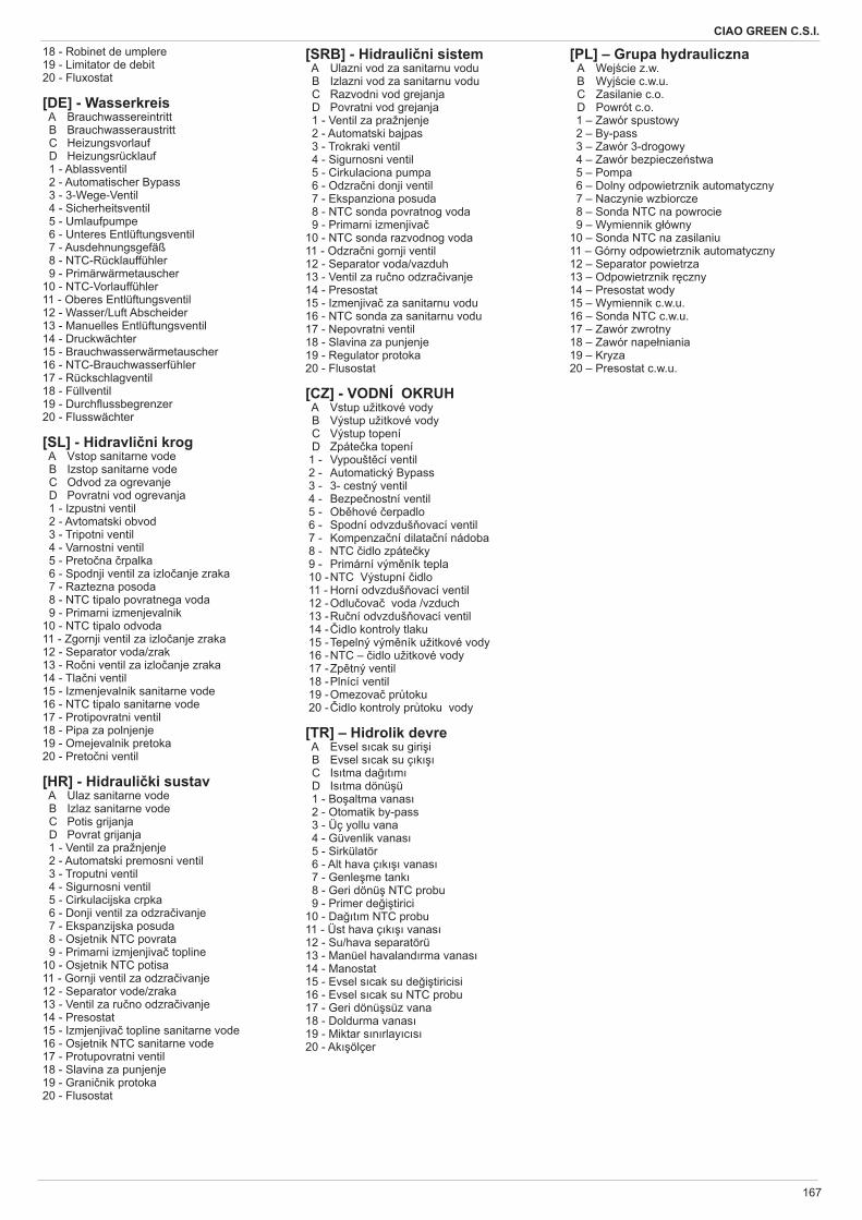
167
CIAO GREEN C.S.I.
18 - Robinet de umplere19 - Limitator de debit20 - Fluxostat [DE] - Wasserkreis A Brauchwassereintritt B Brauchwasseraustritt C Heizungsvorlauf D Heizungsrücklauf 1 - Ablassventil 2 - Automatischer Bypass 3 - 3-Wege-Ventil 4 - Sicherheitsventil 5 - Umlaufpumpe 6 - Unteres Entlüftungsventil 7 - Ausdehnungsgefäß 8 - NTC-Rücklauffühler 9 - Primärwärmetauscher 10 - NTC-Vorlauffühler11 - Oberes Entlüftungsventil12 - Wasser/Luft Abscheider13 - Manuelles Entlüftungsventil14 - Druckwächter15 - Brauchwasserwärmetauscher16 - NTC-Brauchwasserfühler17 - Rückschlagventil 18 - Füllventil19 - Durch ussbegrenzer20 - Flusswächter
[SL] - Hidravli ni krog A Vstop sanitarne vode B Izstop sanitarne vode C Odvod za ogrevanje D Povratni vod ogrevanja 1 - Izpustni ventil 2 - Avtomatski obvod 3 - Tripotni ventil 4 - Varnostni ventil 5 - Preto na rpalka 6 - Spodnji ventil za izlo anje zraka 7 - Raztezna posoda 8 - NTC tipalo povratnega voda 9 - Primarni izmenjevalnik 10 - NTC tipalo odvoda11 - Zgornji ventil za izlo anje zraka12 - Separator voda/zrak13 - Ro ni ventil za izlo anje zraka14 - Tla ni ventil15 - Izmenjevalnik sanitarne vode16 - NTC tipalo sanitarne vode17 - Protipovratni ventil 18 - Pipa za polnjenje19 - Omejevalnik pretoka20 - Preto ni ventil
[HR] - Hidrauli ki sustav A Ulaz sanitarne vode B Izlaz sanitarne vode C Potis grijanja D Povrat grijanja 1 - Ventil za pražnjenje 2 - Automatski premosni ventil 3 - Troputni ventil 4 - Sigurnosni ventil 5 - Cirkulacijska crpka 6 - Donji ventil za odzra ivanje 7 - Ekspanzijska posuda 8 - Osjetnik NTC povrata 9 - Primarni izmjenjiva topline 10 - Osjetnik NTC potisa11 - Gornji ventil za odzra ivanje12 - Separator vode/zraka13 - Ventil za ru no odzra ivanje14 - Presostat15 - Izmjenjiva topline sanitarne vode16 - Osjetnik NTC sanitarne vode17 - Protupovratni ventil 18 - Slavina za punjenje19 - Grani nik protoka20 - Flusostat
[SRB] - Hidrauli ni sistem A Ulazni vod za sanitarnu vodu B Izlazni vod za sanitarnu vodu C Razvodni vod grejanja D Povratni vod grejanja 1 - Ventil za pražnjenje 2 - Automatski bajpas 3 - Trokraki ventil 4 - Sigurnosni ventil 5 - Cirkulaciona pumpa 6 - Odzra ni donji ventil 7 - Ekspanziona posuda 8 - NTC sonda povratnog voda 9 - Primarni izmenjiva 10 - NTC sonda razvodnog voda11 - Odzra ni gornji ventil12 - Separator voda/vazduh13 - Ventil za ru no odzra ivanje14 - Presostat15 - Izmenjiva za sanitarnu vodu16 - NTC sonda za sanitarnu vodu17 - Nepovratni ventil 18 - Slavina za punjenje19 - Regulator protoka20 - Flusostat
[CZ] - VODNÍ OKRUH A Vstup užitkové vody B Výstup užitkové vody C Výstup topení D Zpáte ka topení 1 - Vypoušt cí ventil 2 - Automatický Bypass 3 - 3- cestný ventil 4 - Bezpe nostní ventil 5 - Ob hové erpadlo 6 - Spodní odvzduš ovací ventil 7 - Kompenza ní dilata ní nádoba 8 - NTC idlo zpáte ky 9 - Primární vým ník tepla 10 - NTC Výstupní idlo 11 - Horní odvzduš ovací ventil 12 - Odlu ova voda /vzduch 13 - Ru ní odvzduš ovací ventil 14 - idlo kontroly tlaku 15 - Tepelný vým ník užitkové vody 16 - NTC – idlo užitkové vody 17 - Zp tný ventil 18 - Plnící ventil 19 - Omezova pr toku 20 - idlo kontroly pr toku vody
[TR] – Hidrolik devre A Evsel s cak su giri i B Evsel s cak su ç k C Is tma da t m D Is tma dönü ü 1 - Bo altma vanas 2 - Otomatik by-pass 3 - Üç yollu vana 4 - Güvenlik vanas 5 - Sirkülatör 6 - Alt hava ç k vanas 7 - Genle me tank 8 - Geri dönü NTC probu 9 - Primer de i tirici10 - Da t m NTC probu11 - Üst hava ç k vanas12 - Su/hava separatörü13 - Manüel havaland rma vanas14 - Manostat15 - Evsel s cak su de i tiricisi16 - Evsel s cak su NTC probu17 - Geri dönü süz vana18 - Doldurma vanas19 - Miktar s n rlay c s20 - Ak ölçer
[PL] – Grupa hydrauliczna A Wej cie z.w. B Wyj cie c.w.u. C Zasilanie c.o. D Powrót c.o. 1 – Zawór spustowy 2 – By-pass 3 – Zawór 3-drogowy 4 – Zawór bezpiecze stwa 5 – Pompa 6 – Dolny odpowietrznik automatyczny 7 – Naczynie wzbiorcze 8 – Sonda NTC na powrocie 9 – Wymiennik g ówny10 – Sonda NTC na zasilaniu11 – Górny odpowietrznik automatyczny12 – Separator powietrza13 – Odpowietrznik r czny14 – Presostat wody15 – Wymiennik c.w.u.16 – Sonda NTC c.w.u.17 – Zawór zwrotny18 – Zawór nape niania19 – Kryza20 – Presostat c.w.u.
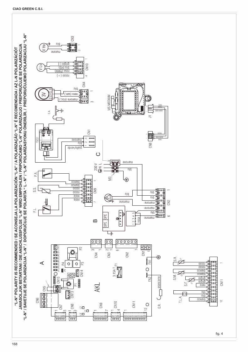
168
CIAO GREEN C.S.I.
A
BC
g. 4
“L-
N”
POLA
RIT
Y IS
REC
OM
MEN
DED
/ SE
AC
ON
SEJA
LA
POLA
RIZ
AC
IÓN
“L-
N”
/ A P
OLA
RIZA
ÇÃO
“L-
N” É
REC
OM
ENDA
DA /
AZ
L-N
PO
LAR
IZÁ
CIÓ
T JA
VASO
LJU
K B
ETA
RTA
NI /
DIE
ANS
CHLU
SSFO
LGE
“L-N
” W
IRD
EMPF
OHL
EN /
PRIP
ORO
AMO
“L-
N” P
OLA
RIZA
CIJO
/ PR
EPO
RUUJ
E SE
PO
LARI
ZACI
JA
“L-N
” / S
AVET
UJE
SE P
OLA
RIZA
CIJA
“L-
N” /
DO
POR
UU
JE S
E PO
LAR
ITA
“ L
- N”
/ “L-
N”
POLA
RZA
SYO
NU
ÖN
ERL
R. /
PR
EPO
RU
UJE
MO
PO
LAR
IZA
CIJ
U “
L-N
”
A
BC
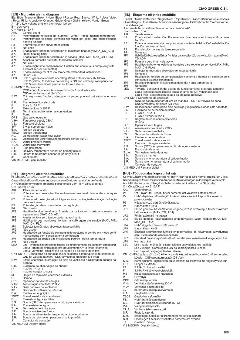
169
CIAO GREEN C.S.I.
[EN] - Multiwire wiring diagramBlu=Blue / Marrone=Brown / Nero=Black / Rosso=Red/ Bianco=White / Viola=Violet / Rosa=Pink / Arancione=Orange / Grigio=Grey / Giallo=Yellow / Verde=GreenA = 24V Low voltage ambient thermostat jumperB = Gas valveC = Fuse 3.15A F AKL Control boardP1 Potentiometer to select off - summer - winter – reset / heating temperatureP2 Potentiometer to select domestic hot water set point, and enable/disable
heating function P3 Thermoregulation curve preselectionP4 Not usedJP1 Enable front knobs for calibration of maximum heat only (MAX_CD_ADJ)JP2 Reset heating timerJP3 Enable front knobs for calibration in service (MAX, MIN, MAX_CH, RLA)JP4 Absolute domestic hot water thermostat selectorJP5 Not usedJP6 Enable night-time compensation function and continuous pump (only with external sensor connected)JP7 Enable management of low temperature/standard installationsJP8 Do not useLED LED 1 (green) to indicate operating status or temporary shutdown LED 2 (yellow) to indicate preheating is ON and chimney sweep function LED 3 (red) to indicate permanent lockout statusCN1-CN15 Connectors (CN6 control panel /outer sensor kit – CN7 local valve kit) - CN5 room thermostat (24 VDC)S.W. Chimney sweep function, interruption of purge cycle and calibration when ena-
bled.E.R. Flame detection electrodeF1 Fuse 3.15A TF External fuse 3.15A FM3 Terminal board for external connectionsP PumpOPE Gas valve operatorV Hv Fan power supply 230VV Lv Fan control signal3W 3-way servomotor valveE.A. Ignition electrodeTSC2 Ignition transformerF.L. Domestic hot water ow switchS.S. Domestic hot water circuit temperature sensor (NTC)P.A. Water pressure switchT.L.A. Water limit thermostat S.F. Flue gas probe S.M. Delivery temperature sensor on primary circuitS.R. Return temperature sensor on primary circuitJ1 Connectors VIS MEDIUM Digital monitor
[ES] - Esquema eléctrico multihiloBlu=Blu / Marrón=Marrone / Negro=Nero /Rojo=Rosso / Blanco=Bianco / Violeta=Viola / Gris=Grigio / Rosa=Rosa / Arancione=Anaranjado / Giallo=Amarillo / Verde=VerdeB = Válvula gasA = Puente termostato ambiente de baja tensión 24VC = Fusible 3.15A F AKL Tarjeta mandoP1 Potenciómetro selección off – verano – invierno – reset / temperatura cale-
facciónP2 Potenciómetro selección set point agua sanitaria, habilitación/deshabilitación
función precalentamiento P3 Preselección curvas de termorregulaciónP4 No usadoJP1 Habilitación botones esféricos frontales para regular sólo la calefacción máxima (MAX_
CD_ADJ)JP2 Puesta a cero timer calefacciónJP3 Habilitación botones esféricos frontales para regular en service (MAX, MIN,
MAX_CH, RLA)JP4 Selector termostatos absolutos de agua sanitariaJP5 No usadoJP6 Habilitación función de compensación nocturna y bomba en continuo sólo
con sonda exterior conectada)JP7 Habilitación gestión instalaciones estándar / baja temperaturaJP8 No utilizarLED 1 (verde) señalización del estado de funcionamiento o parada temporal Led 2 (amarillo) señalización precalentamiento ON y deshollinador Led 3 (rojo) señalización estado de bloqueo de nitivoCN1-CN15 Conectores de conexión (CN6 kit sonda exterior/tablero de mandos – CN7 kit válvula de zona - CN5 termostato ambiente (24 Vdc)S.W. Deshollinador, interrupción ciclo de purga y regulación cuando está habilitada.E.R. Electrodo de detección de llamaF1 Fusible 3.15A TF Fusible exterior 3.15A FR3 Regleta de conexiones exterioresB BombaOPE Operador válvula gasV Hv Alimentación ventilador 230 VV Lv Señal control ventilador3V Servomotor válvula de 3 víasE.A. Electrodo de encendidoTSC2 Transformador de encendidoF.L. Flujostato de agua sanitariaS.S. Sonda (NTC) temperatura circuito de agua sanitariaP.A. Presostato de aguaT.L.A. Termostato límite de agua S.H. Sonda de humos S.A. Sonda envío temperatura circuito primarioS.R. Sonda retorno temperatura circuito primarioJ1 Conector de conexión VIS MEDIUM Pantalla digital
[PT] - Diagrama eléctrico multi larBlu=Blu/Marrom=Marrone/Preto=Nero/Vermelho=Rosso/Branco=Bianco/Violeta=Viola/Cinza=Grigio/Rosa=Rosa/Arancione=Laranja/Giallo=Amarelo/ Verde=VerdeA = Conexão termóstato ambiente baixa tensão 24V - B = Válvula do gásC = Fusível 3.15A F AKL Placa de comandoP1 Potenciómetro selecção off – verão – inverno – reset / temperatura de aque-
cimentoP2 Potenciómetro selecção set point água sanitária, habilitação/desabilitação da função
pré-aquecimento P3 Pré-selecção das curvas de termorregulaçãoP4 Não usadoJP1 Habilitação dos manípulos frontais na calibragem máxima somente do
aquecimento (MAX_CD_ADJ)JP2 Ajustamento a zero temporizador aquecimentoJP3 Habilitação dos manípulos frontais na calibragem em service (MAX, MIN,
MAX_CH, RLA)JP4 Selector termóstatos absolutos água sanitáriaJP5 Não usadoJP6 Habilitação da função de compensação nocturna e bomba em modo contí-
nuo somente com sonda externa conectada)JP7 Habilitação da gestão das instalações padrão / baixa temperaturaJP8 Não utilizarLED Led 1 (verde) sinalização do estado de funcionamento ou paragem temporária Led 2 (amarelo) sinalização pré-aquecimento ON e limpa-chaminés Led 3 (vermelho) sinalização do estado de bloqueio de nitivoCN1-CN15 Conectores de conexão (CN6 kit sonda externa/painel de comandos –
CN7 kit válvula de zona - CN5 termóstato ambiente (24 Vdc)S.W. Limpa-chaminés, interrupção do ciclo de ventilação e calibragem quando ha-
bilitada.E.R. Eléctrodo de observação da chamaF1 Fusível 3.15A TF Fusível externo 3.15A FM3 Régua de terminais conexões externasP BombaOPE Operador da válvulas do gásV Hv Alimentação ventilador 230 VV Lv Sinal controlo do ventilador3V Servomotor válvula de três viasE.A. Eléctrodo de igniçãoTSC2 Transformador de acendimentoF.L. Fluxostato água sanitáriaS.S. Sonda (NTC) temperatura circuito água sanitáriaP.A. Pressostato de águaT.L.A. Termóstato de limite água S.F. Sonda análise dos fumos S.M. Sonda de alimentação temperatura circuito primárioS.R. Sonda de retorno temperatura circuito primárioJ1 Conector de conexão VIS MEDIUM Display digital
[HU] - Többvonalas kapcsolási rajzKék=Blu/Barna=Marrone/Fekete=Nero/Piroa=Rosso/Fehér=Bianco/Lila=Viola/Szürke=Grigio/Rosa=Rózsaszínû/Arancione=Narancssárga/Giallo=Sárga/ Verde=ZöldA = 24V alacsony feszültség szobatermosztát áthidalása - B = GázszelepC = Olvadóbiztosíték 3.15A F AKL Vezérl kártyaP1 Off – nyár– tél– reset / f tési h mérséklet választó potenciométerP2 HMV alapérték, el melegít funkció bekapcsolás/kikapcsolás választó
potenciométer P3 H szabályozó görbék el választásaP4 Használaton kívülJP1 Elüls gombok használatának engedélyezése kizárólag a f tési maximum
kalibrálásához (MAX_CD_ADJ)JP2 F tési számláló nullázásaJP3 Elüls gombok használatának engedélyezése üzem közben (MAX, MIN,
MAX_CH, RLA)JP4 HMV független termosztát választóJP5 Használaton kívülJP6 Éjszakai kiegyenlítési funkció engedélyezése és folyamatos szivattyúzás
csak küls szonda csatlakozással)JP7 Standard / alacsonyh mérséklet rendszerek kezelésének engedélyezéseJP8 Ne használjaLED Led 1 (zöld) m ködési állapot jelzése vagy ideiglenes leállítás Led 2 (sárga) el melegítés ON és kéményseprés jelzése Led 3 (piros) végleges leállás jelzéseCN1-CN15 Csatlakozók (CN6 kültéri szonda készlet/vezérl panel – CN7 zónaszelep
készlet- CN5 szobatermosztát (24 Vdc)S.W. Kéményseprés, légtelenítési ciklus indítása és kalibrálás, ha engedélyezve van.E.R. Láng r elektródaF1 3.15A T olvadóbiztosítékF 3.15A F küls olvadóbiztosítékM3 Küls csatlakozások kapocslécP SzivattyúOPE Gázszelep kezelV Hv Ventilátor tápfeszültség 230 VV Lv Ventilátor ellen rzési jel3V háromutas szelep szervomotorE.A. GyújtóelektródaTSC2 Gyújtó transzformátorF.L. HMV áramlásszabályozóS.S. HMV kör h mérséklet szonda (NTC)P.A. VíznyomáskapcsolóT.L.A. Víz határérték termosztát S.F. Füstgáz szonda S.M. Els dleges f tési kör el remen h mérséklet szondaS.M. Els dleges f tési kör visszatér h mérséklet szondaJ1 Csatlakozódugó VIS MEDIUM Digitális kijelz
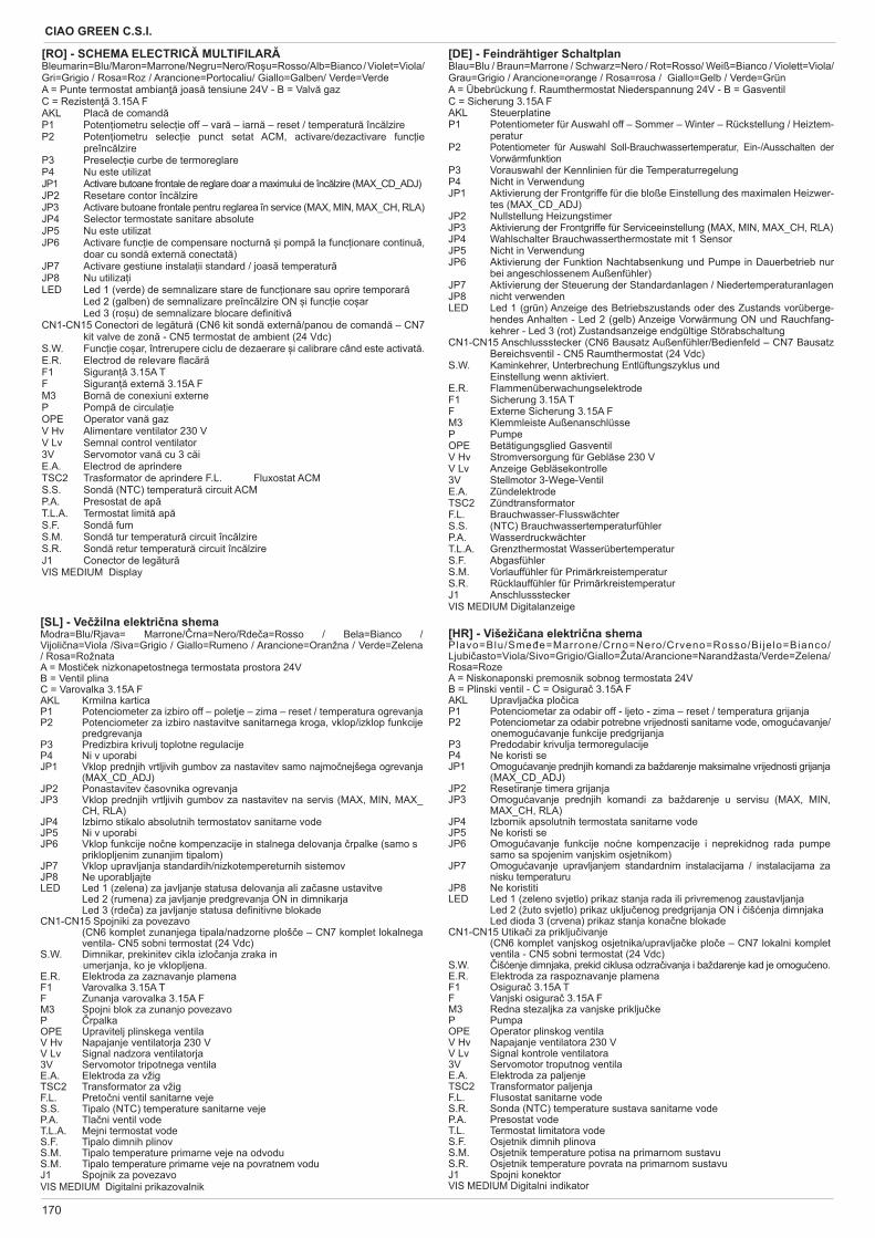
170
CIAO GREEN C.S.I.
[SL] - Ve žilna elektri na shemaModra=Blu/Rjava= Marrone/ rna=Nero/Rde a=Rosso / Bela=Bianco / Vijoli na=Viola /Siva=Grigio / Giallo=Rumeno / Arancione=Oranžna / Verde=Zelena / Rosa=RožnataA = Mosti ek nizkonapetostnega termostata prostora 24VB = Ventil plinaC = Varovalka 3.15A FAKL Krmilna karticaP1 Potenciometer za izbiro off – poletje – zima – reset / temperatura ogrevanjaP2 Potenciometer za izbiro nastavitve sanitarnega kroga, vklop/izklop funkcije
predgrevanja P3 Predizbira krivulj toplotne regulacijeP4 Ni v uporabiJP1 Vklop prednjih vrtljivih gumbov za nastavitev samo najmo nejšega ogrevanja
(MAX_CD_ADJ)JP2 Ponastavitev asovnika ogrevanjaJP3 Vklop prednjih vrtljivih gumbov za nastavitev na servis (MAX, MIN, MAX_
CH, RLA)JP4 Izbirno stikalo absolutnih termostatov sanitarne vodeJP5 Ni v uporabiJP6 Vklop funkcije no ne kompenzacije in stalnega delovanja rpalke (samo s priklopljenim zunanjim tipalom)JP7 Vklop upravljanja standardih/nizkotempereturnih sistemovJP8 Ne uporabljajteLED Led 1 (zelena) za javljanje statusa delovanja ali za asne ustavitve Led 2 (rumena) za javljanje predgrevanja ON in dimnikarja Led 3 (rde a) za javljanje statusa de nitivne blokadeCN1-CN15 Spojniki za povezavo (CN6 komplet zunanjega tipala/nadzorne ploš e – CN7 komplet lokalnega
ventila- CN5 sobni termostat (24 Vdc)S.W. Dimnikar, prekinitev cikla izlo anja zraka in
umerjanja, ko je vklopljena.E.R. Elektroda za zaznavanje plamenaF1 Varovalka 3.15A TF Zunanja varovalka 3.15A FM3 Spojni blok za zunanjo povezavoP rpalkaOPE Upravitelj plinskega ventilaV Hv Napajanje ventilatorja 230 VV Lv Signal nadzora ventilatorja3V Servomotor tripotnega ventilaE.A. Elektroda za vžigTSC2 Transformator za vžigF.L. Preto ni ventil sanitarne vejeS.S. Tipalo (NTC) temperature sanitarne vejeP.A. Tla ni ventil vodeT.L.A. Mejni termostat vode S.F. Tipalo dimnih plinov S.M. Tipalo temperature primarne veje na odvoduS.M. Tipalo temperature primarne veje na povratnem voduJ1 Spojnik za povezavo VIS MEDIUM Digitalni prikazovalnik
[RO] - SCHEMA ELECTRIC MULTIFILARBleumarin=Blu/Maron=Marrone/Negru=Nero/Ro u=Rosso/Alb=Bianco / Violet=Viola/ Gri=Grigio / Rosa=Roz / Arancione=Portocaliu/ Giallo=Galben/ Verde=Verde A = Punte termostat ambian joas tensiune 24V - B = Valv gazC = Rezisten 3.15A F AKL Plac de comandP1 Poten iometru selec ie off – var – iarn – reset / temperatur înc lzire P2 Poten iometru selec ie punct setat ACM, activare/dezactivare func ie
preînc lzire P3 Preselec ie curbe de termoreglareP4 Nu este utilizatJP1 Activare butoane frontale de reglare doar a maximului de înc lzire (MAX_CD_ADJ)JP2 Resetare contor înc lzireJP3 Activare butoane frontale pentru reglarea în service (MAX, MIN, MAX_CH, RLA) JP4 Selector termostate sanitare absoluteJP5 Nu este utilizatJP6 Activare func ie de compensare nocturn i pomp la func ionare continu ,
doar cu sond extern conectat )JP7 Activare gestiune instala ii standard / joas temperaturJP8 Nu utiliza iLED Led 1 (verde) de semnalizare stare de func ionare sau oprire temporar Led 2 (galben) de semnalizare preînc lzire ON i func ie co ar Led 3 (ro u) de semnalizare blocare de nitivCN1-CN15 Conectori de leg tur (CN6 kit sond extern /panou de comand – CN7
kit valve de zon - CN5 termostat de ambient (24 Vdc)S.W. Func ie co ar, întrerupere ciclu de dezaerare i calibrare când este activat .E.R. Electrod de relevare ac rF1 Siguran 3.15A TF Siguran extern 3.15A FM3 Born de conexiuni externeP Pomp de circula ieOPE Operator van gazV Hv Alimentare ventilator 230 V V Lv Semnal control ventilator3V Servomotor van cu 3 c iE.A. Electrod de aprindereTSC2 Trasformator de aprindere F.L. Fluxostat ACMS.S. Sond (NTC) temperatur circuit ACMP.A. Presostat de apT.L.A. Termostat limit apS.F. Sond fumS.M. Sond tur temperatur circuit înc lzire S.R. Sond retur temperatur circuit înc lzire J1 Conector de leg turVIS MEDIUM Display
[DE] - Feindrähtiger SchaltplanBlau=Blu / Braun=Marrone / Schwarz=Nero / Rot=Rosso/ Weiß=Bianco / Violett=Viola/Grau=Grigio / Arancione=orange / Rosa=rosa / Giallo=Gelb / Verde=GrünA = Übebrückung f. Raumthermostat Niederspannung 24V - B = GasventilC = Sicherung 3.15A F AKL SteuerplatineP1 Potentiometer für Auswahl off – Sommer – Winter – Rückstellung / Heiztem-
peraturP2 Potentiometer für Auswahl Soll-Brauchwassertemperatur, Ein-/Ausschalten der
Vorwärmfunktion P3 Vorauswahl der Kennlinien für die TemperaturregelungP4 Nicht in VerwendungJP1 Aktivierung der Frontgriffe für die bloße Einstellung des maximalen Heizwer-
tes (MAX_CD_ADJ)JP2 Nullstellung HeizungstimerJP3 Aktivierung der Frontgriffe für Serviceeinstellung (MAX, MIN, MAX_CH, RLA)JP4 Wahlschalter Brauchwasserthermostate mit 1 SensorJP5 Nicht in VerwendungJP6 Aktivierung der Funktion Nachtabsenkung und Pumpe in Dauerbetrieb nur
bei angeschlossenem Außenfühler)JP7 Aktivierung der Steuerung der Standardanlagen / NiedertemperaturanlagenJP8 nicht verwendenLED Led 1 (grün) Anzeige des Betriebszustands oder des Zustands vorüberge-
hendes Anhalten - Led 2 (gelb) Anzeige Vorwärmung ON und Rauchfang-kehrer - Led 3 (rot) Zustandsanzeige endgültige Störabschaltung
CN1-CN15 Anschlussstecker (CN6 Bausatz Außenfühler/Bedienfeld – CN7 Bausatz Bereichsventil - CN5 Raumthermostat (24 Vdc)
S.W. Kaminkehrer, Unterbrechung Entlüftungszyklus und Einstellung wenn aktiviert.
E.R. FlammenüberwachungselektrodeF1 Sicherung 3.15A TF Externe Sicherung 3.15A FM3 Klemmleiste AußenanschlüsseP PumpeOPE Betätigungsglied GasventilV Hv Stromversorgung für Gebläse 230 VV Lv Anzeige Gebläsekontrolle3V Stellmotor 3-Wege-VentilE.A. ZündelektrodeTSC2 ZündtransformatorF.L. Brauchwasser-FlusswächterS.S. (NTC) BrauchwassertemperaturfühlerP.A. WasserdruckwächterT.L.A. Grenzthermostat Wasserübertemperatur S.F. Abgasfühler S.M. Vorlauffühler für PrimärkreistemperaturS.R. Rücklauffühler für PrimärkreistemperaturJ1 Anschlussstecker VIS MEDIUM Digitalanzeige
[HR] - Višeži ana elektri na shemaPlavo=Blu/Sme e=Marrone/Crno=Nero/Crveno=Rosso/Bi je lo=Bianco/Ljubi asto=Viola/Sivo=Grigio/Giallo=Žuta/Arancione=Narandžasta/Verde=Zelena/ Rosa=RozeA = Niskonaponski premosnik sobnog termostata 24V B = Plinski ventil - C = Osigura 3.15A F AKL Upravlja ka plo icaP1 Potenciometar za odabir off - ljeto - zima – reset / temperatura grijanjaP2 Potenciometar za odabir potrebne vrijednosti sanitarne vode, omogu avanje/
onemogu avanje funkcije predgrijanja P3 Predodabir krivulja termoregulacijeP4 Ne koristi seJP1 Omogu avanje prednjih komandi za baždarenje maksimalne vrijednosti grijanja
(MAX_CD_ADJ)JP2 Resetiranje timera grijanjaJP3 Omogu avanje prednjih komandi za baždarenje u servisu (MAX, MIN,
MAX_CH, RLA)JP4 Izbornik apsolutnih termostata sanitarne vodeJP5 Ne koristi seJP6 Omogu avanje funkcije no ne kompenzacije i neprekidnog rada pumpe
samo sa spojenim vanjskim osjetnikom)JP7 Omogu avanje upravljanjem standardnim instalacijama / instalacijama za
nisku temperaturuJP8 Ne koristitiLED Led 1 (zeleno svjetlo) prikaz stanja rada ili privremenog zaustavljanja Led 2 (žuto svjetlo) prikaz uklju enog predgrijanja ON i iš enja dimnjaka Led dioda 3 (crvena) prikaz stanja kona ne blokadeCN1-CN15 Utika i za priklju ivanje (CN6 komplet vanjskog osjetnika/upravlja ke plo e – CN7 lokalni komplet
ventila - CN5 sobni termostat (24 Vdc)S.W. iš enje dimnjaka, prekid ciklusa odzra ivanja i baždarenje kad je omogu eno.E.R. Elektroda za raspoznavanje plamenaF1 Osigura 3.15A TF Vanjski osigura 3.15A FM3 Redna stezaljka za vanjske priklju keP PumpaOPE Operator plinskog ventilaV Hv Napajanje ventilatora 230 VV Lv Signal kontrole ventilatora3V Servomotor troputnog ventilaE.A. Elektroda za paljenjeTSC2 Transformator paljenjaF.L. Flusostat sanitarne vodeS.R. Sonda (NTC) temperature sustava sanitarne vodeP.A. Presostat vodeT.L. Termostat limitatora vode S.F. Osjetnik dimnih plinova S.M. Osjetnik temperature potisa na primarnom sustavuS.R. Osjetnik temperature povrata na primarnom sustavuJ1 Spojni konektor VIS MEDIUM Digitalni indikator
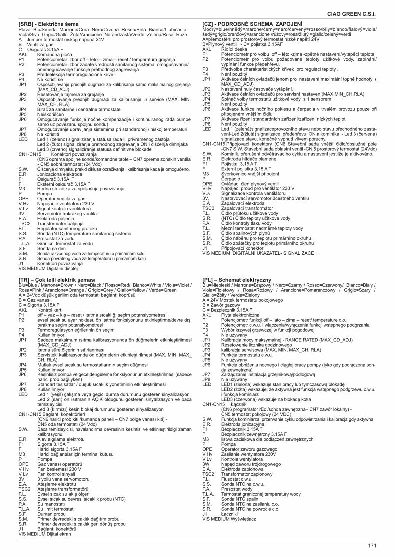
171
CIAO GREEN C.S.I.
[SRB] - Elektri na šemaPlava=Blu/Sme a=Marrone/Crna=Nero/Crvena=Rosso/Bela=Bianco/Ljubi asta=-Viola/Siva=Grigio/Giallo=Žuta/Arancione=Narandžasta/Verde=Zelena/Rosa=RozeA = Jumper termostat niskog napona 24VB = Ventil za gasC = Osigura 3.15A F AKL Komandna plo aP1 Potenciometar izbor off – leto – zima – reset / temperatura grejanjaP2 Potenciometar izbor zadate vrednosti sanitarnog sistema, omogu avanje/
onemogu avanje funkcije prethodnog zagrevanja P3 Predselekcija termoregulacione kriveP4 Ne koristi seJP1 Osposobljavanje prednjih dugmadi za kalibrisanje samo maksimalnog grejanja
(MAX_CD_ADJ)JP2 Resetovanje tajmera za grejanjeJP3 Osposobljavanje prednjih dugmadi za kalibrisanje in service (MAX, MIN,
MAX_CH, RLA)JP4 Bira za sanitarne i centralne termostateJP5 Neiskoriš enJP6 Omogu avanje funkcije no ne kompenzacije i kontinuiranog rada pumpe
samo uz povezanu spoljnu sondu)JP7 Omogu avanje upravljanja sistemima pri standardnoj / niskoj temperaturiJP8 Ne koristitiLED Led 1 (zeleno) signaliziranje statusa rada ili privremenog zastoja Led 2 (žuto) signaliziranje prethodnog zagrevanja ON i iš enja dimnjaka Led 3 (crveno) signaliziranje statusa de nitivne blokadeCN1-CN15 Konektori povezivanja (CN6 oprema spoljne sonde/komandne table – CN7 oprema zonskih ventila
- CN5 sobni termostat (24 Vdc)S.W. iš enje dimnjaka, prekid ciklusa ozra ivanja i kalibrisanje kada je omogu eno.E.R. Jonizaciona elektrodaF1 Osigura 3.15A TF Eksterni osigura 3.15A FM3 Redna stezaljka za spoljašnja povezivanjaP PumpaOPE Operator ventila za gasV Hv Napajanje ventilatora 230 VV Lv Signal kontrole ventilatora3V Servomotor trokrakog ventilaE.A. Elektroda paljenjaTSC2 Transformator paljenjaF.L. Regulator sanitarnog protokaS.S. Sonda (NTC) temperature sanitarnog sistemaP.A. Presostat za voduT.L.A. Grani ni termostat za vodu S.F. Sonda sa dim S.M. Sonda razvodnog voda za temperaturu u primarnom koluS.R. Sonda povratnog voda za temperaturu u primarnom koluJ1 Konektori povezivanja VIS MEDIUM Digitalni displej
[CZ] - PODROBNÉ SCHÉMA ZAPOJENÍModrý=blue/hn dý=marone/ erný=nero/ ervený=rosso/bílý=bianco/fialový=viola/šedý=grigio/oranžový=arancione /r žový=rosa/žlutý =giallo/zelený=verdiA=p emost ní pro prostorový termostat nízké nap tí 24VB=Plynový ventil - C= pojistka 3.15AFAKL ídící deskaP1 Potenciometr pro volbu off – léto -zima -zp tné nastavení/vytáp cí teplotaP2 Potenciometr pro volbu požadované teploty užitkové vody, zapínání/
vypínání funkce p edeh evu.P3 P edvolba charakteristických k ivek pro regulaci teploty .P4 Není použitýJP1 Aktivace elních ovlada jenom pro nastavení maximální topné hodnoty (
MAX_CD_ADJ)JP2 Nastavení nuly asova e vytáp ní.JP3 Aktivace elních ovlada pro servisní nastavení(MAX,MIN_CH,RLA)JP4 Spína volby termostat užitkové vody s 1 sensoremJP5 Není použitýJP6 Aktivace funkce no ního poklesu a erpadla v trvalém provozu pouze p i
p ipojeném vn jším idluJP7 Aktivace ízení standardních za ízení/za ízení nízkých teplotJP8 Není použitýLED Led 1 (zelená)signalizaceprovozního stavu nebo stavu p echodného zasta-
vení-Led 2(žlutá) signalizace p edeh evu ON a kominíka - Led 3 ( ervená) signalizace stavu, kone né vypnutí vlivem poruchy.
CN1-CN15 P ipojovací konektory (CN6 Stavební sada vn jší idlo/obslužné pole -CN7 S.W. Stavební sada oblastní ventil -CN 5 prostorový termostat (24Vdc)
S.W. Kominík, p erušení odv trávacího cyklu a nastavení jestliže je aktivováno.E.R. Elektroda hlída e plameneF1 Pojistka 3,15 A TF Externí pojistka 3,15 A TM3 Svorkovnice vn jší p ipojeníP erpadloOPE Ovládací len plynový ventilVHv Napájecí proud pro ventilátor 230 VVLv Signalizace kontrola ventilátoru3V, Nastavovací servomotor 3cestného ventiluE.A Zapalovací elektrodaTSC2 Zapalovací transformátorF.L. idlo pr toku užitkové vodyS.R. (NTC) idlo teploty užitkové vodyP.A. idlo kontroly tlaku vodyT.L. Mezní termostat nadm rné teploty vodyS.F. idlo spalinových plynS.M. idlo náb hu pro teplotu primárního okruhuS.R. idlo zpáte ky pro teplotu primárního okruhuJ1 P ipojovací konektorVIS MEDIUM DIGITÁLNÍ UKAZATEL- SIGNALIZACE .
[TR] – Çok telli elektrik emasBlu=Blue / Marrone=Brown / Nero=Black / Rosso=Red/ Bianco=White / Viola=Violet / Rosa=Pink / Arancione=Orange / Grigio=Grey / Giallo=Yellow / Verde=GreenA = 24Vdc dü ük gerilim oda termostat ba lant köprüsüB = Gaz vanasC = Sigorta 3.15A FAKL Kontrol kartP1 off – yaz – k – reset / s tma s cakl seçim potansiyometresiP2 evsel s cak su ayar noktas , ön s tma fonksiyonunu etkinle tirme/devre d
b rakma seçim potansiyometresi P3 Termoregülasyon e rilerinin ön seçimiP4 Kullan lm yorJP1 Sadece maksimum s tma kalibrasyonunda ön dü melerin etkinle tirilmesi
(MAX_CD_ADJ)JP2 Is tma süre ölçerinin s f rlanmasJP3 Servisteki kalibrasyonda ön dü melerin etkinle tirilmesi (MAX, MIN, MAX_
CH, RLA)JP4 Mutlak evsel s cak su termostatlar n n seçim dü mesiJP5 Kullan lm yorJP6 Kesintisiz pompa ve gece dengeleme fonksiyonunun etkinle tirilmesi (sadece harici prob ba l yken)JP7 Standart tesisatlar / dü ük s cakl k yönetiminin etkinle tirilmesiJP8 Kullan lm yorLED Led 1 (ye il) çal ma veya geçici durma durumunu gösteren sinyalizasyon Led 2 (sar ) ön s tman n AÇIK oldu unu gösteren sinyalizasyon ve baca
temizleyicisi Led 3 (k rm z ) kesin blokaj durumunu gösteren sinyalizasyonCN1-CN15 Ba lant konektörleri (CN6 harici prob kiti /kumanda paneli – CN7 bölge vanas kiti) - CN5 oda termostat (24 Vdc)S.W. Baca temizleyicisi, havaland rma devresinin kesintisi ve etkinle tirildi i zaman
kalibrasyonu.E.R. Alev alg lama elektrotuF1 Sigorta 3.15A TF Harici sigorta 3.15A FM3 Harici ba lant lar için terminal kutusuP PompaOPE Gaz vanas operatörüV Hv Fan beslemesi 230 VV Lv Fan kontrol sinyali3V 3 yollu vana servomotoruE.A. Ate leme elektrotuTSC2 Ate leme transformatörüF.L. Evsel s cak su ak ölçeriS.S. Evsel s cak su devresi s cakl k probu (NTC)P.A. Su manostatT.L.A. Su limit termostatS.F. Duman probuS.M. Primer devredeki s cakl k da t m probuS.R. Primer devredeki s cakl k geri dönü probuJ1 Ba lant konektörü VIS MEDIUM Dijital ekran
[PL] – Schemat elektrycznyBlu=Niebieski / Marrone=Br zowy / Nero=Czarny / Rosso=Czerwony/ Bianco=Bia y / Viola=Fioletowy / Rosa=Ró owy / Arancione=Pomaranczowy / Grigio=Szary / Giallo= ó ty / Verde=ZielonyA = 24V Mostek termostatu pokojowegoB = Zawór gazowyC = Bezpiecznik 3.15A F AKL P yta elektronicznaP1 Potencjometr funkcji off – lato – zima – reset/ temperature c.o.P2 Potencjometr c.w.u. I w czenia/wy czenia funkcji wst pnego podgrzaniaP3 Wybór krzywej grzewczej w funkcji pogodowejP4 Nie u ywanyJP1 Kalibracja mocy maksymalnej - RANGE RATED (MAX_CD_ADJ)JP2 Resetowanie licznika godzinowegoJP3 kalibracja serwisowa (MAX, MIN, MAX_CH, RLA)JP4 Funkcja termostatu c.w.u.JP5 Nie u ywanyJP6 Funkcja obni enia nocnego i ci g ej pracy pompy (tyko gdy pod czona son-
da zewn trzna) JP7 Zarz dzanie instalacj grzejnikow /pod ogowJP8 Nie u ywanyLED LED1 (zielona) wskazuje stan pracy lub tymczasow blokad LED2 ( ó ta) wskazuje, e aktywna jest funkcja wst pnego podgrzewu c.w.u.
i funkcja kominiarz LED3 (czerwona) wskazuje na blokad kot a CN1-CN15 czniki (CN6 programator rEc /sonda zewn trzna– CN7 zawór lokalny) - CN5 termostat pokojowy (24 VDC)S.W. Funkcja kominiarza, przerwanie cyklu odpowietrzania i kalibracja gdy aktywna.E.R. Elektroda jonizacyjnaF1 Bezpiecznik 3.15A TF Bezpiecznik zewn trzny 3.15A FM3 listwa zaciskowa dla pod cze zewn trznychP PompaOPE Operator zaworu gazowegoV Hv Zasilanie wentylatora 230VV Lv Kontrola wentylatora3W Nap d zaworu trójdrogowegoE.A. Elektroda zap onowaTSC2 Transformator zap onowyF.L. Flusostat c.w.u.S.S. Sonda NTC na c.w.u.P.A. Presostat wodyT.L.A. Termostat granicznej temperatury wody S.F. Sonda NTC spalin S.M. Sonda NTC na zasilaniu c.o.S.R. Sonda NTC na powrocie c.o.J1 czniki VIS MEDIUM Wy wietlacz
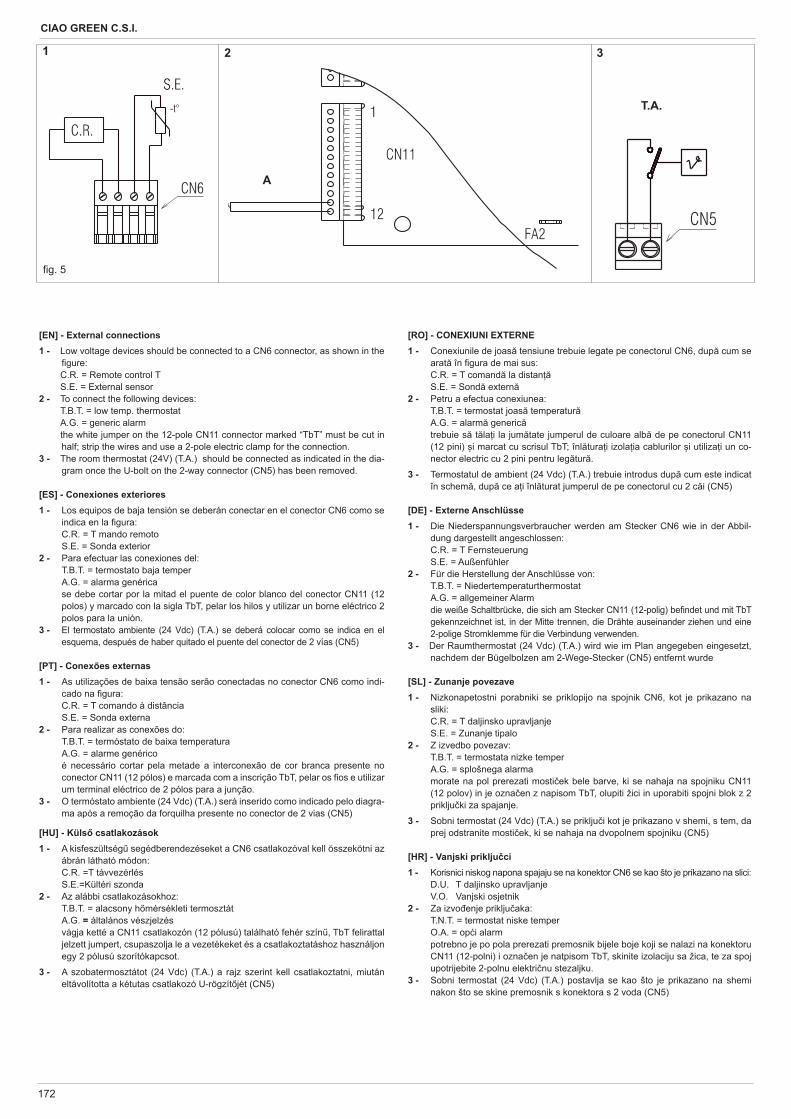
172
CIAO GREEN C.S.I.
[EN] - External connections1 - Low voltage devices should be connected to a CN6 connector, as shown in the
gure: C.R. = Remote control T S.E. = External sensor2 - To connect the following devices: T.B.T. = low temp. thermostat A.G. = generic alarm the white jumper on the 12-pole CN11 connector marked “TbT” must be cut in
half; strip the wires and use a 2-pole electric clamp for the connection.3 - The room thermostat (24V) (T.A.) should be connected as indicated in the dia-
gram once the U-bolt on the 2-way connector (CN5) has been removed.
[ES] - Conexiones exteriores1 - Los equipos de baja tensión se deberán conectar en el conector CN6 como se
indica en la gura: C.R. = T mando remoto S.E. = Sonda exterior2 - Para efectuar las conexiones del: T.B.T. = termostato baja temper A.G. = alarma genérica se debe cortar por la mitad el puente de color blanco del conector CN11 (12
polos) y marcado con la sigla TbT, pelar los hilos y utilizar un borne eléctrico 2 polos para la unión.
3 - El termostato ambiente (24 Vdc) (T.A.) se deberá colocar como se indica en el esquema, después de haber quitado el puente del conector de 2 vías (CN5)
[PT] - Conexões externas1 - As utilizações de baixa tensão serão conectadas no conector CN6 como indi-
cado na gura: C.R. = T comando à distância S.E. = Sonda externa2 - Para realizar as conexões do: T.B.T. = termóstato de baixa temperatura A.G. = alarme genérico é necessário cortar pela metade a interconexão de cor branca presente no
conector CN11 (12 pólos) e marcada com a inscrição TbT, pelar os os e utilizar um terminal eléctrico de 2 pólos para a junção.
3 - O termóstato ambiente (24 Vdc) (T.A.) será inserido como indicado pelo diagra-ma após a remoção da forquilha presente no conector de 2 vias (CN5)
[HU] - Küls csatlakozások1 - A kisfeszültség segédberendezéseket a CN6 csatlakozóval kell összekötni az
ábrán látható módon: C.R. =T távvezérlés S.E.=Kültéri szonda2 - Az alábbi csatlakozásokhoz: T.B.T. = alacsony h mérsékleti termosztát A.G. = általános vészjelzés vágja ketté a CN11 csatlakozón (12 pólusú) található fehér szín , TbT felirattal
jelzett jumpert, csupaszolja le a vezetékeket és a csatlakoztatáshoz használjon egy 2 pólusú szorítókapcsot.
3 - A szobatermosztátot (24 Vdc) (T.A.) a rajz szerint kell csatlakoztatni, miután eltávolította a kétutas csatlakozó U-rögzít jét (CN5)
g. 5
A
T.A.
1 2 3
[RO] - CONEXIUNI EXTERNE1 - Conexiunile de joas tensiune trebuie legate pe conectorul CN6, dup cum se
arat în gura de mai sus: C.R. = T comand la distan S.E. = Sond extern2 - Petru a efectua conexiunea: T.B.T. = termostat joas temperatur A.G. = alarm generic trebuie s t la i la jum tate jumperul de culoare alb de pe conectorul CN11
(12 pini) i marcat cu scrisul TbT; înl tura i izola ia cablurilor i utiliza i un co-nector electric cu 2 pini pentru leg tur .
3 - Termostatul de ambient (24 Vdc) (T.A.) trebuie introdus dup cum este indicat în schem , dup ce a i înl turat jumperul de pe conectorul cu 2 c i (CN5)
[DE] - Externe Anschlüsse1 - Die Niederspannungsverbraucher werden am Stecker CN6 wie in der Abbil-
dung dargestellt angeschlossen: C.R. = T Fernsteuerung S.E. = Außenfühler2 - Für die Herstellung der Anschlüsse von: T.B.T. = Niedertemperaturthermostat A.G. = allgemeiner Alarm die weiße Schaltbrücke, die sich am Stecker CN11 (12-polig) be ndet und mit TbT
gekennzeichnet ist, in der Mitte trennen, die Drähte auseinander ziehen und eine 2-polige Stromklemme für die Verbindung verwenden.
3 - Der Raumthermostat (24 Vdc) (T.A.) wird wie im Plan angegeben eingesetzt, nachdem der Bügelbolzen am 2-Wege-Stecker (CN5) entfernt wurde
[SL] - Zunanje povezave1 - Nizkonapetostni porabniki se priklopijo na spojnik CN6, kot je prikazano na
sliki: C.R. = T daljinsko upravljanje S.E. = Zunanje tipalo2 - Z izvedbo povezav: T.B.T. = termostata nizke temper A.G. = splošnega alarma morate na pol prerezati mosti ek bele barve, ki se nahaja na spojniku CN11
(12 polov) in je ozna en z napisom TbT, olupiti žici in uporabiti spojni blok z 2 priklju ki za spajanje.
3 - Sobni termostat (24 Vdc) (T.A.) se priklju i kot je prikazano v shemi, s tem, da prej odstranite mosti ek, ki se nahaja na dvopolnem spojniku (CN5)
[HR] - Vanjski priklju ci1 - Korisnici niskog napona spajaju se na konektor CN6 se kao što je prikazano na slici: D.U. T daljinsko upravljanje V.O. Vanjski osjetnik2 - Za izvo enje priklju aka: T.N.T. = termostat niske temper O.A. = op i alarm potrebno je po pola prerezati premosnik bijele boje koji se nalazi na konektoru
CN11 (12-polni) i ozna en je natpisom TbT, skinite izolaciju sa žica, te za spoj upotrijebite 2-polnu elektri nu stezaljku.
3 - Sobni termostat (24 Vdc) (T.A.) postavlja se kao što je prikazano na shemi nakon što se skine premosnik s konektora s 2 voda (CN5)
173
CIAO GREEN C.S.I.
[SRB] - Spoljašnja povezivanja1 - Potroša i niskog napona bi e povezani na konektor CN6 kao što je prikazano na
slici : C.R. T daljinsko upravljanje S.E. Spoljna sonda2 - Da bi se obavilo povezivanje: T.B.T. = termostata niske temperature A.G. = opšteg alarma potrebno je prese i na pola beli džamper koji se nalazi na konektoru CN11
(12 iglica) i koji je ozna en natpisom TbT, oljuštiti kablove i koristiti elektri nu stezaljku sa 2 pola za spajanje.
3 - Sobni termostat (24 Vdc) se dodaje kao što je prikazano na šemi nakon što se skine džamper koji se nalazi na konektoru 2 (CN5)
[CZ] - EXTERNÍ P IPOJENÍ 1 - Nízkonap ové spot ebi e se p ipojují na konektor CN6 jak je znázorn no na
obrázku : C.R = Dálkové ovládání T S.E = Vn jší idlo
2 - Pro provedení p ípoje od : T.B.T. = Nízkoteplotní termostat A.G. = Všeobecný alarm Zílý spínací m stek, nacházející se na zástr ce CN 11(12 polová ) a je ozna en
TbT, rozd lit uprost ed. Dráty roztáhnout od sebe a použít 2- polovou proudo-vou svorku pro spojení.
3 - Prostorový termostat(24 Vdc ) (T.A.) je použit jak je v nákresu uvedeno , po té co t mínkový svorník byl na 2cestné zástr ce (CN5) odstran n.
[TR] – Elektrik ba lant lar1 - Dü ük gerilim ayg tlar , ekilde gösterildi i gibi CN6 konektörü üzerine
ba lanmal d r: C.R. = Uzaktan kumanda T S.E. = Harici prob2 - A a dakinin ba lant lar n gerçekle tirmek için: T.B.T. = dü ük s cak. termostat A.G. = genel alarm CN11 üzerinde bulunan (12 kutup) ve TbT yaz s ile i aretlenen beyaz renkteki
ba lant köprüsünü yar ya kesmek gerekir; telleri soyunuz ve ba lant için 2 ku-tuplu bir elektrik kelepçesi kullan n z.
3 - Oda termostat (24 Vdc), 2 yollu konektör (CN5) üzerinde bulunan u c vatas n kald rd ktan sonra emada gösterildi i gibi tak lmal d r.
A.G. = allgemeiner Alarm die weiße Schaltbrücke, die sich am Stecker CN11 (12-polig) be ndet und mit TbT
gekennzeichnet ist, in der Mitte trennen, die Drähte auseinander ziehen und eine 2-polige Stromklemme für die Verbindung verwenden.
3 - Der Raumthermostat (24 Vdc) (T.A.) wird wie im Plan angegeben eingesetzt, nachdem der Bügelbolzen am 2-Wege-Stecker (CN5) entfernt wurde
[PL] – Pod czenia zewn trzne1 - Urz dzenia niskonapi ciowe powinny zosta wykonane tak jak na schemacie do
kostki CN6: C.R. = Zdalne sterowanie S.E. = Sonda zewn trzna2 - Pod czenie urz dze : TT.B.T. = termostat niskiej temperatury A.G. = kasowanie alarmu Bia y mostek na kostce 12-polowej CN11 opisany “TbT musi zosta przeci ty,
po cz przewody i u yj 2-polowego zacisku aby po czy3 - Termostat pokojowy (24V) (T.A.) nale y pod czy po uprzednik usuni ciu mo-
stka na CN5
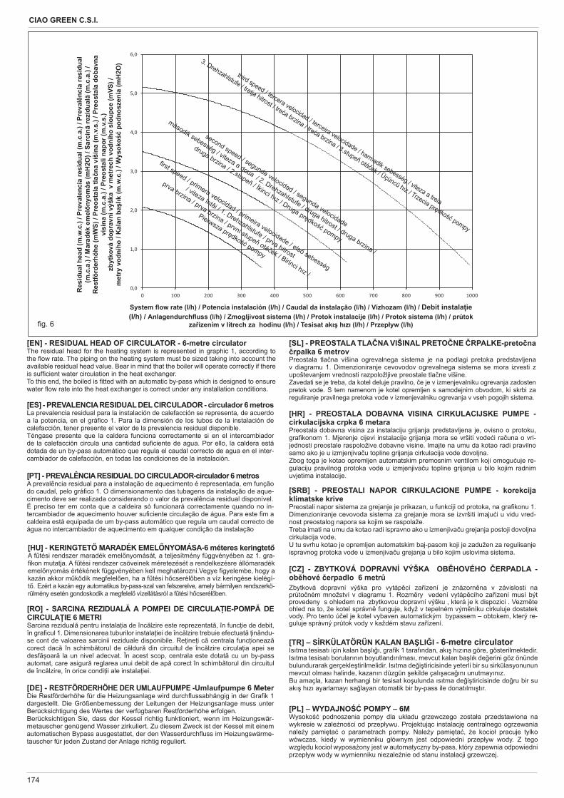
174
CIAO GREEN C.S.I.
g. 6
System ow rate (l/h) / Potencia instalación (l/h) / Caudal da instalação (l/h) / Vízhozam (l/h) / Debit instala ie (l/h) / Anlagendurch uss (l/h) / Zmogljivost sistema (l/h) / Protok instalacije (l/h) / Protok sistema (l/h) / pr tok
za ízením v litrech za hodinu (l/h) / Tesisat ak h z (l/h) / Przep yw (l/h)
Res
idua
l hea
d (m
.w.c
.) / P
reva
lenc
ia re
sidu
al (m
.c.a
.) / P
reva
lênc
ia re
sidu
al
(m.c
.a.)
/ Mar
adék
em
elny
omás
(mH
2O) /
Sar
cin
rezi
dual
(m.c
.a.)
/ R
estfö
rder
höhe
(mW
S) /
Preo
stal
a tla
na v
išin
a (m
.v.s
.) / P
reos
tala
dob
avna
vi
sina
(m.c
.a.)
/ Pre
osta
li na
por (
m.v
.s.)
zbyt
ková
dop
ravn
í výš
ka v
met
rech
vod
ního
slo
upce
(mVS
) /m
etry
vod
ního
/ K
alan
ba
lk (m
.w.c
.) / W
ysok
o p
odno
szen
ia (m
H2O
)
[EN] - RESIDUAL HEAD OF CIRCULATOR - 6-metre circulatorThe residual head for the heating system is represented in graphic 1, according to the ow rate. The piping on the heating system must be sized taking into account the available residual head value. Bear in mind that the boiler will operate correctly if there is suf cient water circulation in the heat exchanger.To this end, the boiled is tted with an automatic by-pass which is designed to ensure water ow rate into the heat exchanger is correct under any installation conditions.
[ES] - PREVALENCIA RESIDUAL DEL CIRCULADOR - circulador 6 metros La prevalencia residual para la instalación de calefacción se representa, de acuerdo a la potencia, en el grá co 1. Para la dimensión de los tubos de la instalación de calefacción, tener presente el valor de la prevalencia residual disponible.Téngase presente que la caldera funciona correctamente si en el intercambiador de la calefacción circula una cantidad su ciente de agua. Por ello, la caldera está dotada de un by-pass automático que regula el caudal correcto de agua en el inter-cambiador de calefacción, en todas las condiciones de la instalación.
[PT] - PREVALÊNCIA RESIDUAL DO CIRCULADOR-circulador 6 metros A prevalência residual para a instalação de aquecimento é representada, em função do caudal, pelo grá co 1. O dimensionamento das tubagens da instalação de aque-cimento deve ser realizada considerando o valor da prevalência residual disponível.É preciso ter em conta que a caldeira só funcionará correctamente quando no in-tercambiador de aquecimento houver su ciente circulação de água. Para este m a caldeira está equipada de um by-pass automático que regula um caudal correcto de água no intercambiador de aquecimento em qualquer condição da instalação
[HU] - KERINGTET MARADÉK EMEL NYOMÁSA-6 méteres keringtetA f tési rendszer maradék emel nyomását, a teljesítmény függvényében az 1. gra- kon mutatja. A f tési rendszer csöveinek méretezését a rendelkezésre állómaradék emel nyomás értékének függvényében kell meghatározni.Vegye gyelembe, hogy a kazán akkor m ködik megfelel en, ha a f tési h cserél ben a víz keringése kielégí-t . Ezért a kazán egy automatikus by-pass-szal van felszerelve, amely bármilyen rendszerkö-rülmény esetén gondoskodik a megfelel vízellátásról a f tési h cserél ben.
[RO] - SARCINA REZIDUAL A POMPEI DE CIRCULA IE-POMP DE CIRCULA IE 6 METRISarcina rezidual pentru instala ia de înc lzire este reprezentat , în func ie de debit, în gra cul 1. Dimensionarea tuburilor instala iei de înc lzire trebuie efectuat inându-se cont de valoarea sarcinii reziduale disponibile. Re ine i c centrala func ioneaz corect dac în schimb torul de c ldur din circuitul de înc lzire circula ia apei se desf oar la un nivel adecvat. În acest scop, centrala este dotat cu un by-pass automat, care asigur reglarea unui debit de ap corect în schimb torul din circuitul de înc lzire, în orice condi ii ale instala iei.
[DE] - RESTFÖRDERHÖHE DER UMLAUFPUMPE -Umlaufpumpe 6 MeterDie Restförderhöhe für die Heizungsanlage wird durch ussabhängig in der Gra k 1 dargestellt. Die Größenbemessung der Leitungen der Heizungsanlage muss unter Berücksichtigung des Wertes der verfügbaren Restförderhöhe erfolgen.Berücksichtigen Sie, dass der Kessel richtig funktioniert, wenn im Heizungswär-metauscher genügend Wasser zirkuliert. Zu diesem Zweck ist der Kessel mit einem automatischen Bypass ausgestattet, der den Wasserdurch uss im Heizungswärme-tauscher für jeden Zustand der Anlage richtig reguliert.
[SL] - PREOSTALA TLA NA VIŠINAL PRETO NE RPALKE-preto na rpalka 6 metrov
Preostala tla na višina ogrevalnega sistema je na podlagi pretoka predstavljena v diagramu 1. Dimenzioniranje cevovodov ogrevalnega sistema se mora izvesti z upoštevanjem vrednosti razpoložljive preostale tla ne višine.Zavedati se je treba, da kotel deluje pravilno, e je v izmenjevalniku ogrevanja zadosten pretok vode. S tem namenom je kotel opremljen s samodejnim obvodom, ki skrbi za reguliranje pravilnega pretoka vode v izmenjevalniku ogrevanja v vseh pogojih sistema.
[HR] - PREOSTALA DOBAVNA VISINA CIRKULACIJSKE PUMPE - cirkulacijska crpka 6 metara Preostala dobavna visina za instalaciju grijanja predstavljena je, ovisno o protoku, gra konom 1. Mjerenje cijevi instalacije grijanja mora se vršiti vode i ra una o vri-jednosti preostale raspoložive dobavne visine. Imajte na umu da kotao radi pravilno samo ako je u izmjenjiva u topline grijanja cirkulacija vode dovoljna.Zbog toga je kotao opremljen automatskim premosnim ventilom koji omogu uje re-gulaciju pravilnog protoka vode u izmjenjiva u topline grijanja u bilo kojim radnim uvjetima instalacije.
[SRB] - PREOSTALI NAPOR CIRKULACIONE PUMPE - korekcija klimatske krive Preostali napor sistema za grejanje je prikazan, u funkciji od protoka, na gra konu 1.Dimenzioniranje cevovoda sistema za grejanje mora se izvršiti imaju i u vidu vred-nost preostalog napora sa kojim se raspolaže.Treba imati na umu da kotao radi ispravno ako u izmenjiva u grejanja postoji dovoljna cirkulacija vode.U tu svrhu kotao je opremljen automatskim baj-pasom koji je zadužen za regulisanje ispravnog protoka vode u izmenjiva u grejanja u bilo kojim uslovima sistema.
[CZ] - ZBYTKOVÁ DOPRAVNÍ VÝŠKA OB HOVÉHO ERPADLA - ob hové erpadlo 6 metr Zbytková dopravní výška pro vytáp cí za ízení je znázorn na v závislosti na pr to ném množství v diagramu 1. Rozm ry vedení vytáp cího za ízení musí být provedeny s ohledem na zbytkovou dopravní výšku , která je k dispozici . Vezm te ohled na to, že kotel správn funguje, když v tepelném vým níku cirkuluje dostatek vody. Pro tento ú el je kotel vybaven automatickým bypassem – obtokem, který re-guluje správný pr tok vody v každém stavu za ízení.
[TR] – S RKÜLATÖRÜN KALAN BA LI I - 6-metre circulatorIs tma tesisat için kalan ba l , gra k 1 taraf ndan, ak h z na göre, gösterilmektedir. Is tma tesisat borular n n boyutland r lmas , mevcut kalan ba l k de erini göz önünde bulundurarak gerçekle tirilmelidir. Is tma de i tiricisinde yeterli bir su sirkülasyonunun mevcut olmas halinde, kazan n düzgün ekilde çal aca n unutmay n z.Bu amaçla, kazan herhangi bir tesisat ko ulunda s tma de i tiricisinde do ru bir su ak h z ayarlamay sa layan otomatik bir by-pass ile donat lm t r.
[PL] – WYDAJNO POMPY – 6MWysoko podnoszenia pompy dla uk adu grzewczego zosta a przedstawiona na wykresie w zale no ci od przep ywu. Projektuj c instalacj centralnego ogrzewania nale y pami ta o parametrach pompy. Nale y pami ta , e kocio pracuje tylko wówczas, kiedy w wymienniku g ównym jest odpowiedni przep yw wody. Z tego wzgl du kocio wyposa ony jest w automatyczny by-pass, który zapewnia odpowiedni przep yw wody w wymienniku niezale nie od stanu instalacji grzewczej.
0,0
1,0
2,0
3,0
4,0
5,0
6,0
0 100 200 300 400 500 600 700 800 900 1000
rst speed / primera velocidad / primeira velocidade / els sebesség
/ viteza întâi / 1. Drehzahlstufe / prva hitrost
prva brzina / prva brzina / první stupe otá ek / Birinci h z /
Pierwsza pr dko pompy
second speed / segunda velocidad / segunda velocidade
második sebesség / viteza a doua / 2. Drehzahlstufe / druga hitrost / druga brzina /
druga brzina / 2.stupe / kinci h z / Druga pr dko pompy
third speed / tercera velocidad / terceira velocidade / harmadik sebesség / viteza a treia
3. Drehzahlstufe / tretja hitrost / tre a brzina / tre a brzina / 3.stupe otá ek / Üçüncü h z / Trzecia pr dko pompy
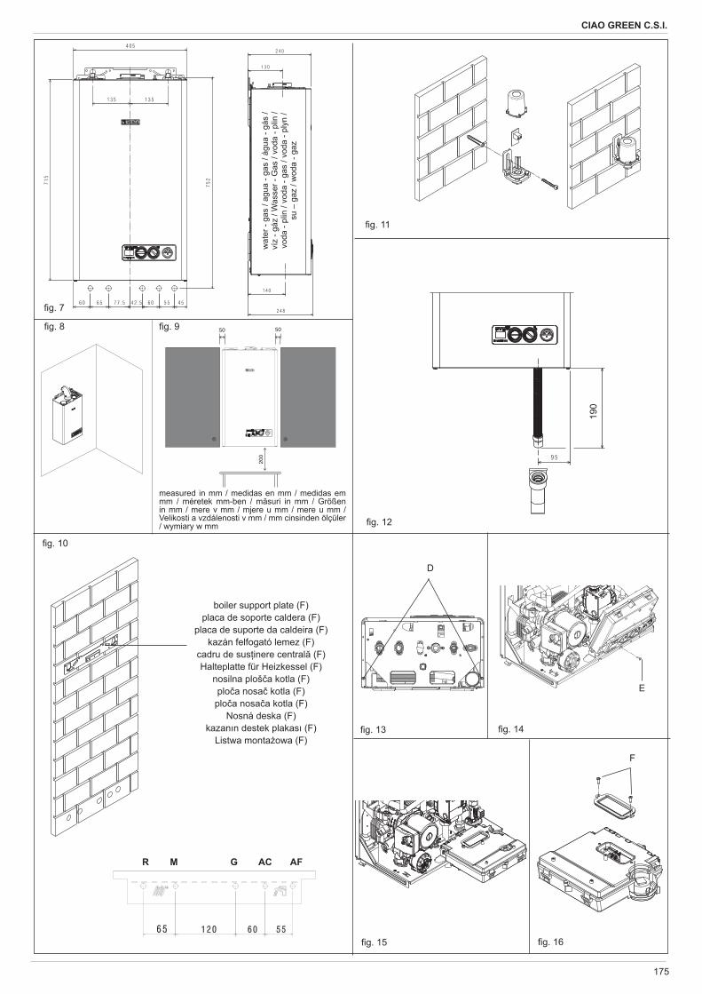
175
CIAO GREEN C.S.I.
g. 13
D
g. 14
E
g. 7
g. 10
g. 11
g. 12
g. 15 g. 16
F
g. 8
measured in mm / medidas en mm / medidas em mm / méretek mm-ben / m suri in mm / Größen in mm / mere v mm / mjere u mm / mere u mm / Velikosti a vzdálenosti v mm / mm cinsinden ölçüler / wymiary w mm
g. 9
boiler support plate (F)placa de soporte caldera (F)
placa de suporte da caldeira (F)kazán felfogató lemez (F)
cadru de sus inere central (F)Halteplatte für Heizkessel (F)
nosilna ploš a kotla (F)plo a nosa kotla (F)plo a nosa a kotla (F)
Nosná deska (F)kazan n destek plakas (F)
Listwa monta owa (F)
R M G AC AF
wat
er -
gas
/ agu
a - g
as /
água
- gá
s /
víz
- gáz
/ W
asse
r - G
as /
voda
- pl
in /
voda
- pl
in /
voda
- ga
s / v
oda
- ply
n /
su –
gaz
/ w
oda
- gaz
190
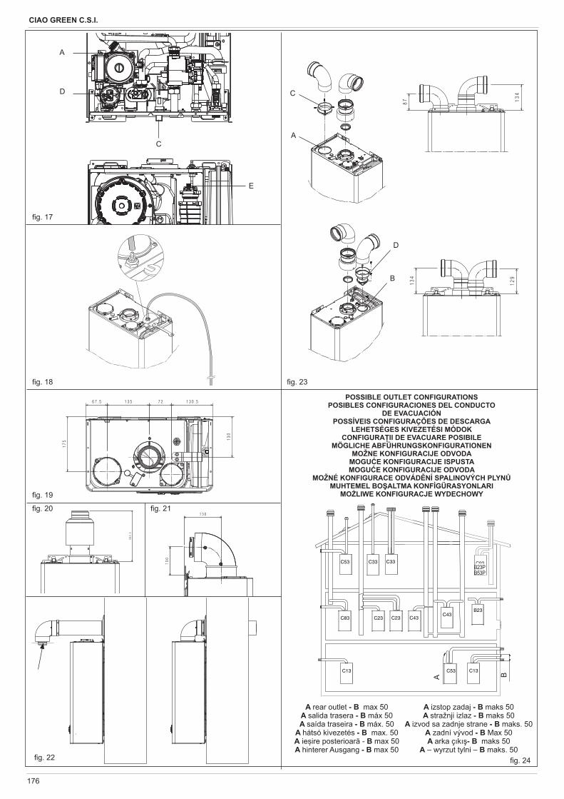
176
CIAO GREEN C.S.I.
POSSIBLE OUTLET CONFIGURATIONSPOSIBLES CONFIGURACIONES DEL CONDUCTO
DE EVACUACIÓNPOSSÍVEIS CONFIGURAÇÕES DE DESCARGA
LEHETSÉGES KIVEZETÉSI MÓDOKCONFIGURA II DE EVACUARE POSIBILE
MÖGLICHE ABFÜHRUNGSKONFIGURATIONEN MOŽNE KONFIGURACIJE ODVODA
MOGU E KONFIGURACIJE ISPUSTAMOGU E KONFIGURACIJE ODVODA
MOŽNÉ KONFIGURACE ODVÁD NÍ SPALINOVÝCH PLYNMUHTEMEL BO ALTMA KONF GÜRASYONLARI
MO LIWE KONFIGURACJE WYDECHOWY
C93
BA
A rear outlet - B max 50 A salida trasera - B máx 50A saída traseira - B máx. 50
A hátsó kivezetés - B max. 50 A ie ire posterioar - B max 50A hinterer Ausgang - B max 50
g. 17
g. 18
g. 19
g. 20 g. 21
g. 22
g. 23
g. 24
B23PB53P
D
A
C
E
A izstop zadaj - B maks 50A stražnji izlaz - B maks 50
A izvod sa zadnje strane - B maks. 50A zadní vývod - B Max 50A arka ç k - B maks 50
A – wyrzut tylni – B maks. 50
A
B
C
D
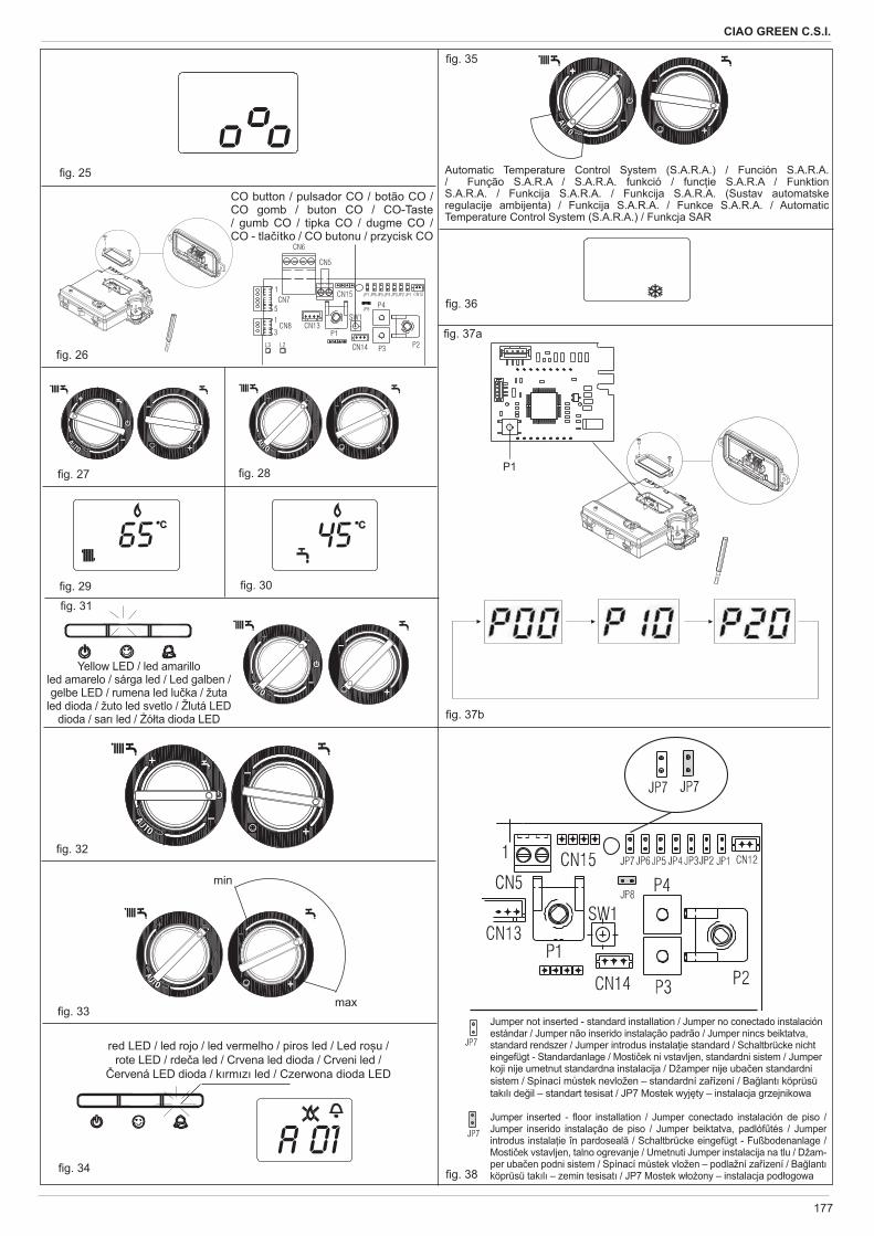
177
CIAO GREEN C.S.I.
CO button / pulsador CO / botão CO / CO gomb / buton CO / CO-Taste / gumb CO / tipka CO / dugme CO / CO - tla ítko / CO butonu / przycisk CO
Yellow LED / led amarilloled amarelo / sárga led / Led galben / gelbe LED / rumena led lu ka / žuta
led dioda / žuto led svetlo / Žlutá LED dioda / sar led / ó ta dioda LED
g. 25
g. 26
g. 27 g. 28
g. 29 g. 30
g. 31
g. 32
g. 33
����
red LED / led rojo / led vermelho / piros led / Led ro u / rote LED / rde a led / Crvena led dioda / Crveni led / ervená LED dioda / k rm z led / Czerwona dioda LED
g. 34
Automatic Temperature Control System (S.A.R.A.) / Función S.A.R.A. / Função S.A.R.A / S.A.R.A. funkció / func ie S.A.R.A / Funktion S.A.R.A. / Funkcija S.A.R.A. / Funkcija S.A.R.A. (Sustav automatske regulacije ambijenta) / Funkcija S.A.R.A. / Funkce S.A.R.A. / Automatic Temperature Control System (S.A.R.A.) / Funkcja SAR
g. 35
g. 36
Jumper not inserted - standard installation / Jumper no conectado instalación estándar / Jumper não inserido instalação padrão / Jumper nincs beiktatva, standard rendszer / Jumper introdus instala ie standard / Schaltbrücke nicht eingefügt - Standardanlage / Mosti ek ni vstavljen, standardni sistem / Jumper koji nije umetnut standardna instalacija / Džamper nije uba en standardni sistem / Spínací m stek nevložen – standardní za ízení / Ba lant köprüsü tak l de il – standart tesisat / JP7 Mostek wyj ty – instalacja grzejnikowa
Jumper inserted - oor installation / Jumper conectado instalación de piso / Jumper inserido instalação de piso / Jumper beiktatva, padlóf tés / Jumper introdus instala ie în pardoseal / Schaltbrücke eingefügt - Fußbodenanlage / Mosti ek vstavljen, talno ogrevanje / Umetnuti Jumper instalacija na tlu / Džam-per uba en podni sistem / Spínací m stek vložen – podlažní za ízení / Ba lant köprüsü tak l – zemin tesisat / JP7 Mostek w o ony – instalacja pod ogowa g. 38
���
�� �
min
max
g. 37a
g. 37b
P1
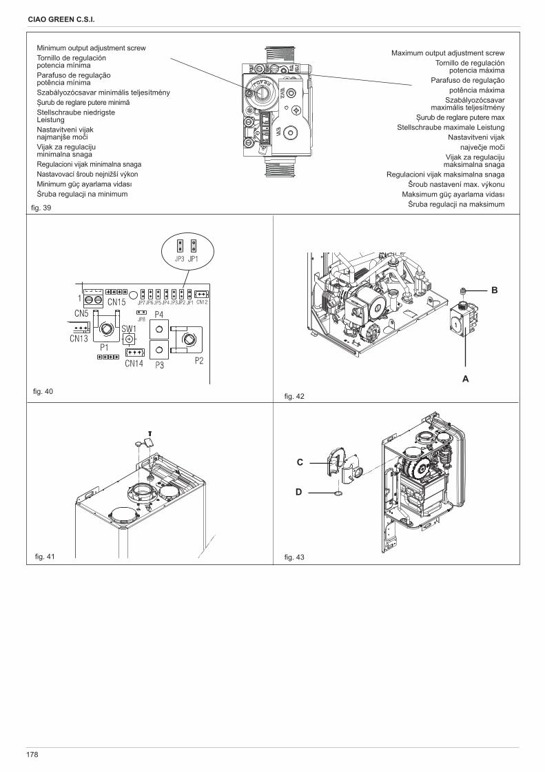
178
CIAO GREEN C.S.I.
Maximum output adjustment screwTornillo de regulación
potencia máximaParafuso de regulação
potência máximaSzabályozócsavar
maximális teljesítményurub de reglare putere max
Stellschraube maximale LeistungNastavitveni vijak
najve je mo iVijak za regulaciju
maksimalna snagaRegulacioni vijak maksimalna snaga
Šroub nastavení max. výkonuMaksimum güç ayarlama vidas
ruba regulacji na maksimum
Minimum output adjustment screwTornillo de regulación potencia mínimaParafuso de regulação potência mínimaSzabályozócsavar minimális teljesítmény
urub de reglare putere minimStellschraube niedrigste LeistungNastavitveni vijak najmanjše mo iVijak za regulaciju minimalna snagaRegulacioni vijak minimalna snagaNastavovací šroub nejnižší výkonMinimum güç ayarlama vidas
ruba regulacji na minimum
g. 39
g. 40
g. 41
A
B
C
D
g. 42
g. 43
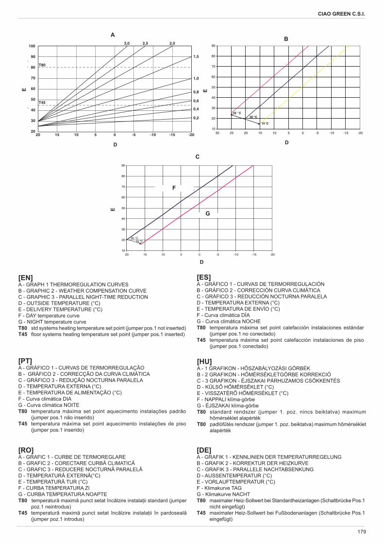
179
CIAO GREEN C.S.I.
[PT]A - GRÁFICO 1 - CURVAS DE TERMORREGULAÇÃOB - GRÁFICO 2 - CORRECÇÃO DA CURVA CLIMÁTICAC - GRÁFICO 3 - REDUÇÃO NOCTURNA PARALELAD - TEMPERATURA EXTERNA (°C)E - TEMPERATURA DE ALIMENTAÇÃO (°C)F - Curva climática DIAG - Curva climática NOITET80 temperatura máxima set point aquecimento instalações padrão
(jumper pos.1 não inserido)T45 temperatura máxima set point aquecimento instalações de piso
(jumper pos.1 inserido)
[ES]A - GRÁFICO 1 - CURVAS DE TERMORREGULACIÓN B - GRÁFICO 2 - CORRECCIÓN CURVA CLIMÁTICAC - GRÁFICO 3 - REDUCCIÓN NOCTURNA PARALELAD - TEMPERATURA EXTERNA (°C)E - TEMPERATURA DE ENVÍO (°C)F - Curva climática DÍAG - Curva climática NOCHET80 temperatura máxima set point calefacción instalaciones estándar
(jumper pos.1 no conectado)T45 temperatura máxima set point calefacción instalaciones de piso
(jumper pos.1 conectado)
[EN]A - GRAPH 1 THERMOREGULATION CURVESB - GRAPHIC 2 - WEATHER COMPENSATION CURVEC - GRAPHIC 3 - PARALLEL NIGHT-TIME REDUCTIOND - OUTSIDE TEMPERATURE (°C)E - DELIVERY TEMPERATURE (°C)F - DAY temperature curveG - NIGHT temperature curveT80 std systems heating temperature set point (jumper pos.1 not inserted)T45 oor systems heating temperature set point (jumper pos.1 inserted)
C
E
D
10
20
30
40
50
60
70
80
90
-20-15-10-505101520
Curva climatica GIORNO
Curva climatica NOTTE
16 °C20 °C
F
GE
D
B
20 °C25 ° C
15 °C
10
20
30
40
50
60
70
80
90
-20-15-10-5051015202530
D
A
Ep
()
20
30
40
50
60
70
80
90
100
-20
0,2
0,4
0,6
0,8
1,0
1,5
2,02,53,0
T80
T45
-15-10-505101520
[HU]A - 1 GRAFIKON - H SZABÁLYOZÁSI GÖRBÉKB - 2 GRAFIKON - H MÉRSÉKLETGÖRBE KORREKCIÓC - 3 GRAFIKON - ÉJSZAKAI PÁRHUZAMOS CSÖKKENTÉSD - KÜLS H MÉRSÉKLET (°C)E - VISSZATÉR H MÉRSÉKLET (°C)F - NAPPALI klíma-görbeG - ÉJSZAKAI klíma-görbeT80 standard rendszer (jumper 1. poz. nincs beiktatva) maximum
h mérséklet alapértékT80 padlóf tés rendszer (jumper 1. poz. beiktatva) maximum h mérséklet
alapérték
[RO]A - GRAFIC 1 - CURBE DE TERMOREGLAREB - GRAFIC 2 - CORECTARE CURB CLIMATICC - GRAFIC 3 - REDUCERE NOCTURN PARALELD - TEMPERATUR EXTERN (°C)E - TEMPERATUR TUR (°C)F - CURBA TEMPERATURA ZIG - CURBA TEMPERATURA NOAPTET80 temperatur maxim punct setat înc lzire instala ii standard (jumper
poz.1 neintrodus)T45 temperatur maxim punct setat înc lzire instala ii în pardoseal
(jumper poz.1 introdus)
[DE]A - GRAFIK 1 - KENNLINIEN DER TEMPERATURREGELUNGB - GRAFIK 2 - KORREKTUR DER HEIZKURVEC - GRAFIK 3 - PARALLELE NACHTABSENKUNGD - AUSSENTEMPERATUR (°C)E - VORLAUFTEMPERATUR (°C)F - Klimakurve TAGG - Klimakurve NACHTT80 maximaler Heiz-Sollwert bei Standardheizanlagen (Schaltbrücke Pos.1
nicht eingefügt)T45 maximaler Heiz-Sollwert bei Fußbodenanlagen (Schaltbrücke Pos.1
eingefügt)
180
CIAO GREEN C.S.I.
[SL] A - DIAGRAM 1 - KRIVULJE TOPLOTNE REGULACIJEB - DIAGRAM 2 - POPRAVEK KLIMATSKE KRIVULJEC - DIAGRAM 3 - NO NO PARALELNO ZNIŽANJED - ZUNANJA TEMPERATURA (°C)E - TEMPERATURA NA ODVODU (°C)F - Klimatska krivulja - DNEVNAG - Klimatska krivulja - NO NAT80 najvišja temperatura nastavitve ogrevanja std sistemov (mosti ek
poz.1 ni vstavljen)T45 najvišja temperatura nastavitve ogrevanja talnih sistemov (mosti ek
poz.1 je vstavljen)
[HR]A - GRAFIKON 1 - KRIVULJE TERMOREGULACIJEB - GRAFIKON 2 - KOREKCIJA KLIMATSKE KRIVULJEC - GRAFIKON 3 - SMANJENJE NO NE PARALELED - ZUNANJA TEMPERATURA (°C)E - TEMPERATURA NA ODVODU (°C)F - Klimatska krivulja DANG - Klimatska krivulja NOT80 potrebna vrijednost maksimalne temperature grijanja na standardnim
instalacijama (jumper pol.1 koji nije umetnut)T45 potrebna vrijednost maksimalne temperature grijanja na instalacijama
na tlu (jumper pol.1 umetnut)
[SRB]A - GRAFIKON 1 - TERMOREGULACIONE KRIVEB - GRAFIKON 2 - KOREKCIJA KLIMATSKE KRIVEC - GRAFIKON 3 - PARALELNA NO NA REDUKCIJAD - SPOLJNA TEMPERATURA (°C)E - TEMPERATURA RAZVODNOG VODA(°C)F - Klimatska kriva DANG -Klimatska kriva NOT80 zadata vrednost maksimalne temperature grejanja u sistemima std
(džamper pozicija 1 nije uba en)T45 zadata vrednost maksimalne temperature grejanja u podnim sistemima
(džamper pozicija 1 uba en)
[CZ] A - GRAF 1-CHARAKTERISTIKA REGULACE TEPLOTY B - GRAF 2 -KOREKC TOPNÉ K IVKYC - GRAF 3 -PARALELNÍ NO NÍ ÚTLUM (SNÍŽENÍ TEPLOTY )D - VN JŠÍ TEPLOTA (OC)E - P EDSTIHOVÁ -NÁB HOVÁ TEPLOTA (OC)F - Klimatická k ivka DENG - Klimatická k ivka NOCT80 maximální topná požadovaná hodnota teploty u standardních
vytáp cích za ízení(spínací m stek Pos.1 nevložen)T45 maximální topná požadovaná hodnota teploty u podlažních vytáp cích
za ízení(spínací m stek Pos.1 vložen)
[TR]A - GRAF K 1 – TERMOREGÜLASYON E R LERB - GRAF K 2 – KL MAT K DENGELEME E R SC - GRAF K 3 – PARALEL GECE DÜ Ü ÜD - DI SICAKLIK (°C)E - DA ITIM SICAKLI I (°C)F - Gündüz s cakl e risiG - Gece s cakl e risiT80 std tesisatlar n maksimum s tma s cakl ayar noktas (ba lant
köprüsü poz. 1 tak l de il)T45 zemin tesisatlar n n maksimum s tma s cakl ayar noktas (ba lant
köprüsü poz. 1 tak l )
[PL]A - WYKRES 1 – KRZYWE GRZEWCZEB - WYKRES 2 – KRZYWA REGULACJI POGODOWEJC - WYKRES 3 – OBNI ENIE NOCNED - TEMPERATURA ZEWN TRZNA (°C)E - TEMPERATURA ZASILANIA (°C)F - krzywa temperatury DNIAG - krzywa temperatury NOCYT80 zadana temperatura instalacji grzejnikowej (zworka nie umieszczona)T45 zadana temperatura instalacji pod ogowej (zworka umieszczona)
Via Risorgimento, 13 23900 Lecco (LC)
Italy
Cod
. 200
7970
8 - 0
4/14
- E
d. 1