Embed Size (px)
Citation preview

JOURNAL OF THE OPTICAL SOCIETY OF AMERICA
Cine Spectrograph
DONALD J. LOVELL* AND HAROLD S. STEWART, Naval Research Laboratory, Washington, D. C.
AND
SEYMOUR ROSINJ Farrand Optical Company, New York, New York(Received May 4,* 1954)
To study time varying spectral characteristics, a spectrograph has been devised capable of recordingsuccessive spectra of an object on continuously driven 70-mm film. Each of the 5000 exposures per secondrecorded by the instrument consists of five spectra recorded simultaneously. Four of these are of the selectedsource, with the fifth being of a tungsten source to provide spectral calibration of the film. The film isbrought out of a magazine, past a film drum, and onto a takeup spool. The drum has sprocket teeth whichengage a length of film in the neighborhood where exposures are made. Attached to the drum is a skirt inwhich are cut eighty slanting slots. These rotate directly in front of a slit assembly consisting of five parallelslits each fitted with a neutral density filter. The slots act as a shutter, admitting light only through theareas of the slits exposed by a slot. Since unit magnification optics are used, the image travels with the film.Spectrograms of sources available in the laboratory are discussed.
INTRODUCTION
To observe the characteristics of rapidly varyingspectra, a cine spectrograph has been developed
at the Naval Research Laboratory. This instrument hasrecorded 5000 exposures per second and has been usedat speeds as slow as one exposure per second.
Each exposure consists of four spectra of a sourceunder consideration and one spectrum for calibrationpurposes. The four spectra of the considered source areexposed through individual neutral-density filterswhich are density-stepped to permit an exposure rangeof 33 to one. A system of five parallel slits is employed,one for each of the five spectra. Traveling slots arrangedto sweep across the slits perform the function of ashutter for the instrument. These slots are sloped at45 degrees to provide a vertical separation of the ex-posed position of adjoining slits.
Quartz prisms and lithium fluoride-quartz lenssystems are used so that exposures in the spectral regionfrom 250 to 800 mu can be obtained. This spectrum isdispersed over approximately five centimeters onstandard 70-mm film. A calibrated time scale is in-troduced onto the side of the film to allow film velocityand exposure duration calculations to be made.
MECHANICAL FEATURES
As shown in Fig. 1, the film is fed from a magazineattached to the top of the instrument onto a drumwhose sprocket teeth mesh with the film sprocket holes.To eliminate unnecessary bending in travel, the pathof the film is made nearly tangential to the film drum.From the drum, the film is fed to the takeup spoolwhere the power ordinarily is applied to drive the system.
For high-speed applications, a three-quarter-horse-power motor coupled directly to the takeup spoolaccelerates the film to a speed of about 100 ft/sec in
* Present address: Industrial Research Laboratories, Baltimore,Maryland.
t Present address: Scanoptic, Inc., New York, New York.
0.25 second. For slower-speed applications, a syn-chronous motor attached to the film drum maintainsa constant film speed. A low-torque motor attached tothe film takeup spool through a friction clutch pro-vides sufficient power to wind up the film withoutplacing undue strain on the synchronous motor.
Solid flanges on the takeup spool permit removal ofthe film under daylight conditions. Although themagazine itself must be loaded in a darkroom, all otheroperations may be done in the daylight.
OPTICAL COMPONENTS
Light is admitted to the spectrograph through theslit assembly in the front of the instrument. Rotatingdirectly behind this slit assembly is a skirt attached tothe film drum. Eighty slots cut in the skirt behave asshutters as the skirt rotates. The slots are sloped at a45-degree angle to expose vertically displaced areas ofadjacent slits. The light that is thus selected is reflectedby two plane mirrors to the collimating lens of the dis-persing assembly.
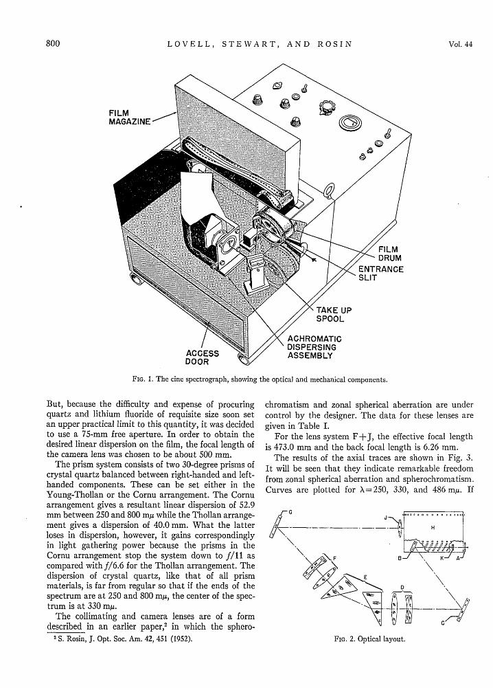
The path of the light through the cine spectrographis best shown by reference to the optical layout of Fig. 2.Light is admitted through the slit system A, passesthrough a compensating plate K, and is reflected by theplane mirrors B and C to the collimating lens D. Fromhere, the light beam is refracted by the prism assemblyE and is converged as it leaves the prism assembly bythe camera lens F. A plane mirror G reflects this conethrough the field lens J onto the image plane coincidentwith the edge of the film drum H. The collimating lensand camera lens are identical in design, the positiveelements being made of lithium fluoride and thenegative elements of crystal quartz.'
Since extremely short exposures were required, it wasdesirable to use as high a physical aperture as possible.
I Use of the combination of quartz with lithium fluoride toprovide a color corrected lens for the ultraviolet was suggestedby Stockbarger and Cartwright, J. Opt. Soc. Am. 29, 29 (1939).
799
VOLUME 44, NUMBER 10 OCTOBER, 1954
LOVELL, STEWART, AND ROSIN
FIG. 1. The cine spectrograph, showing the optical and mechanical components.
But, because the difficulty and expense of procuringquartz and lithium fluoride of requisite size soon setan upper practical limit to this quantity, it was decidedto use a 75-mm free aperture. In order to obtain thedesired linear dispersion on the film, the focal length ofthe camera lens was chosen to be about 500 mm.
The prism system consists of two 30-degree prisms ofcrystal quartz balanced between right-handed and left-handed components. These can be set either in theYoung-Thollan or the Cornu arrangement. The Cornuarrangement gives a resultant linear dispersion of 52.9mm between 250 and 800 mu while the Thollan arrange-ment gives a dispersion of 40.0 mm. What the latterloses in dispersion, however, it gains correspondinglyin light gathering power because the prisms in theCornu arrangement stop the system down to f/11 ascompared withf/6.6 for the Thollan arrangement. Thedispersion of crystal quartz, like that of all prismmaterials, is far from regular so that if the ends of thespectrum are at 250 and 800 mu, the center of the spec-trum is at 330 mg.
The collimating and camera lenses are of a formdescribed in an earlier paper,' in which the sphero-
2 S. Rosin, J. Opt. Soc. Am. 42, 451 (1952).
chromatism and zonal spherical aberration are undercontrol by the designer. The data for these lenses aregiven in Table I.
For the lens system F+J, the effective focal lengthis 473.0 mm and the back focal length is 6.26 mm.
The results of the axial traces are shown in Fig. 3.It will be seen that they indicate remarkable freedomfrom zonal spherical aberration and spherochromatism.Curves are plotted for X= 250, 330, and 486 m If
FIG. 2. Optical layout.
800 Vol. 44

CINE SPECTROGRAPH
35
3C
25
, 20
1
I0
5
1.0 2.0AXIAL INTERCEPT (MM)
3.0FI.3 xa rcso teotclcmoet
FIG. 3. Axial traces of the optical componentsused in the spectrograph.
TABLE I. Optical system for cine spectrograph.
Optical Radium ofcomponent curvature Thickness Diameter
(Fig. 2) (mm) (mm) (mm) Material
151.6Lithium
Collimating 14.0 77.0 fluoride
lens, -174.3 jD 25.0 Air
or -135.4Crystal
Camera 4.0 69.0 Jt quartz
lens, 249.4Lithium
F 10.0 69.0 . fluoride
-313.5 J
Air
Field 65.57
lens, 8.0 42.OX 10.0 Fusedl 95.05 quartz
J t- 95.05 J
another curve were plotted for \ = 800 mu, it wouldbe coincident with that for X = 250 m/u. The primarycolor correction was adjusted so that the ends of thespectrum (250, 800 mu) are coincident and the middleof the spectrum was at a minimum focal length. Thisinterval of some 1.6 mm then represented the secondaryspectrum. With two lenses in series, this interval wouldbe doubled.
In the absence of other aberrations, this secondaryspectrum would result in a backwards curving field of64 mm radius over the spectrum extent of 40 mm for theThollan arrangement and of 111 mm radius over the52.9 mm spectrum extent of the Cornu arrangement.Counterbalancing this backwards curve is the normalforwards curve of the tangential field of the cameralens which, since the sine condition is very closelyachieved in this design, is given by the equation
T= P+3F,where T is the curvature of the tangential field, P isthe Petzval sum, and F is the refracting power of thelens. Numerically for the camera lens, P= 1.0 diopterand F= 2.0 diopters, which results in a tangential fieldcurvature of 143 mm. Because this curvature is notsufficient to overcome the backwards secondary spec-trum field curvature of either the Cornu or Thollanarrangement, a field lens has been added near the focalplane to make up the difference. In this way, the spec-trum is laid down in the film plane normal to the opticaxis, and the plane is perfectly flat. To provide sym-metry to the optical system, a compensating plate isintroduced immediately behind the skirt containingthe slots. How well the design achievements wererealized in practice may be seen in Fig. 4 which showsan enlargement of a test plate of the mercury spectrum.
CINE FEATURES
An enlarged schematic view of the film drum (Fig. 5)shows the film as it is engaged at the drum. In orderthat the relative positions of the drum, skirt, slots, slits,and film may be seen, the intervening optics and filmpressure plate are not drawn in this figure, but an in-dication is made of the area where the spectrum isformed.
Identical collimating and camera lenses form in-verted images of the slits with unit magnification. Asthe slot moves up across the slits, images of the exposedslit areas move down the image plane with the samespeed. The film moving down on the periphery of thedrum thus has no relative motion with respect to the
FIG. 4. Mercury spectrum made with optical components of the cine spectrograph.
I I
: i
I II II I
I I1
I I
I I
I IIII I
QUr
October 1954 801

LOVELL, STEWART, AND ROSIN
FILMDRUM
FORMED
TEETH TO FILM R [MM6 a ENGAGE FILM
;\// 11 SLIT S EMBY
o .^r\@ / /-g (DETIL A)_
ATTACHED SKIRTWITH° $ 80 SLANTING SLOTS
70-MM FLM
FIG. 5. Film drum and slit system.
FIG. 6. The cine spectrograph slit assembly.
image, because the slots used to expose the slits alsoare on the periphery and diametrically opposite theimage position. The detail in the figure shows the slitassembly in front of the film drum skirt. The sloping
displacement of the slits allows each to be exposedsimultaneously by the traveling slot.
The slit assembly is displayed in still greater detailin Fig. 6. The two quartz plates shown, when sand-wiched together, form the slit assembly. One plate,1X 12X 15 mm, is lacquered opaque after which areasare cut away to form the slits. The slit admitting thecalibration light is placed nearest to the edge of theplate, and four source slits are parallel to this with 1 mmseparating each slit.
Another quartz plate, X loX iomm, is used tosupport the neutral-density step filters. The steps,formed by depositing evaporated platinum on thequartz surface, have thicknesses such that transmissionsteps of 3, 10, and 30 percent of the clear quartz areformed. The four source slits are covered by these threesteps and one clear area.
One edge of the filter plate is beveled at 45 degreesand aluminized to reflect the calibration light into thespectrograph. This arrangement permits the calibra-tion light to be brought in at right angles to the opticalaxis of the spectrograph. Since the slots are sloped at45 degrees, the exposed area of each slit will be verticallydisplaced in relation to the others. Consequently, thespectrum formed for each slit also will be verticallydisplaced relative to the other spectra. And since theslits are also horizontally displaced, there is a corre-sponding wavelength displacement for each spectrum.
TYPICAL RESULTS
Spectrograms, typical of those produced by the spec-trograph, are exhibited in Figs. 7-9. Figure 7 is thespectra of an ac powered carbon arc. The red end ofeach spectrum is at the top of the figure. One calibrationspectrum is seen on the left of each exposure, and the1000-cycle timing light appears at the bottom. Theresulting 120 cycle excitation frequency of the lineemission is recognized, and the continuous backgroundemission of the heated electrodes is also noted.
The spectra of an exploding flash bulb is exhibitedin Figs. 8 and 9. The former figure shows the patternof the entire explosion, while the latter exhibits onlythe first five milliseconds. Exposure speeds of about4000 per second were used in obtaining these spectra.
During the February 1952 solar eclipse the cine
FIG. 7. A cine spectrogram of a carbon arc operated on 60-cycle power.
802 Vol. 44

CINE SPECTROGRAPH
E 110 1 M a =
FIG. 8. A cine spectrogram of a flash bulb explosion.
Since the transmissions of each step could be measuredaccurately, it was possible to determine the relativeexposure for each step. This knowledge, plus measure-ments of the resulting film density, is sufficient toplot a characteristic curve for the emulsion at the wave-length and exposure duration selection. From a seriesof such curves the relative variations in spectral emis-sion of a source as a function of time can be determined.To determine absolute values of this variation requiresa separate run on a calibrated source. A tungsten ribbon-filament lamp, used with this instrument for calibrationpurposes, provides the linkFbetween the known spectralsource and the unknown.* Because the techniques used in evaluating data fromthe cine spectrograph are very much the same as thosepracticed widely by many radiometrists, there is noneed for elaboration here. It should be mentioned,however, that the failure of the reciprocity law must be
FIG. 9. The first five milliseconds of the flash bulb explosion.
spectrograph was used to determine the limb darkeningof the sun.3 For this purpose, a speed of about oneexposure per second was used.
DATA REDUCTION
The exposure steps produced by the neutral densityfilters were clearly seen in the exhibited spectrograms.
3 Heyden, Beck, Lovell, Fussell, Hancock, and Hulburt,Astrophys. J. 118, 412 (1953).
examined if the calibration source and unknown sourceare exposed at different speeds.
By means of a timing light also provided with thisinstrument, electronically controlled light pulses areimaged onto the film to give discrete timing references.One-millisecond tiniing markers are produced for high-speed applications, while time intervals of one secondare used at slow speed. Other intervals could be ob-tained for application at other speeds.
803October 1954
I.