Embed Size (px)
Citation preview
電路學Circuits: Engineering Concepts and Analysis of
Linear Electric Circuits
李百祺

Course Information
• 時間: 週五 9:10am-12:10pm• 地點: 電二106• 教科書: Circuits, by A. Bruce Carlson,
Brooks/Cole, 2000.‧聯絡方式: 博理館425室 (33663551)
Email: [email protected]: http://ultrasound.ee.ntu.edu.twà課程
à電路學

Course Content
• Chapter 1: 1.4, 1.5• Chapter 2: 2.3, 2.4, 2.5• Chapter 3: 3.2, 3.3• Chapter 4: 4.1, 4.2, 4.3• Chapter 5.3• Chapter 6: 6.1, 6.2, 6.3• Chapter 7: 7.1, 7.2• Chapter 9: 9.1, 9.2, 9.3, 9.4• Chapter 11: 11.1, 11.2, 11.4• Chapter 13: 13.1, 13.2, 13.3• Chapter 14: 14.1, 14.2, 14.3

Grading and Homework
• 考試: 5次小考及期末考• 評分方式: 小考共佔60% (最低分的一次
小考不記分)、期末考佔40%• 習題: Homework problems will be
assigned but not graded. Selected problems will be
solved in class.

電路學學什麼?
• 學電路• 學電路分析• 學電路分析與設計• 學線性電路分析與設計• 學集總 (lumped) 線性電路分析與設計• 學基本代數分析方法及應用phasor, Fourier
transform, Laplace transform 之分析方法
Chapter 1: Circuit Variables and Laws

Chapter 1: Outline

Chapter 1: Circuit Variables and Laws
• Quick review of (self reading):– Definition of Current, Voltage, Polarity– Definition of Energy, Power, Source and Load– Ohm’s law and Resistors
• Kirchhoff’s laws– Current (KCL)– Voltage (KVL)
• Elementary Circuit Analysis– Series and Parallel

Fundamentals

Current: Formal Definition
• Current is the net flow of charges, per time, past an arbitrary “plane” in some kind of electrical device.
• We will only be concerned with the flow of positive charges. A negative charge moving to the right is conceptually the same as a positive charge moving to the left.
dqi
dt=Current,
typically inAmperes [A]
Charge, typically in Coulombs [C]
Time, typically in seconds [s]

The Ampere
• The unit of current is the Ampere, which is a flow of 1 Coulomb of charge per second, i.e.:
1[A] = 1[Coul/sec] • Current is defined in terms of the flow of
positive charges.One coulomb of positive charges per second
flowing from left to right - is equivalent to -
one coulomb of negative charges per second flowing from right to left.
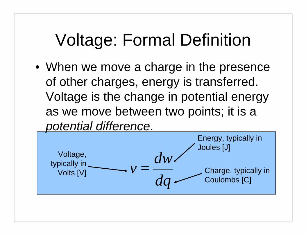
Voltage: Formal Definition• When we move a charge in the presence
of other charges, energy is transferred. Voltage is the change in potential energy as we move between two points; it is a potential difference.
Voltage,typically in
Volts [V]
Energy, typically in Joules [J]
Charge, typically in Coulombs [C]
dwv
dq=
Volt• The unit of voltage is the Volt. A Volt is
defined as a Joule per Coulomb. • Voltage is defined in terms of the energy
gained or lost by the movement of positivecharges.
One Joule of energy is lost from an electric system when a Coulomb of positive charges moves from one potential to another potential that is one Volt lower.

Hydraulic Analogy:Voltage and Current
height ~ voltageflow rate ~ current
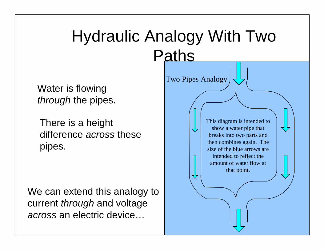
Hydraulic Analogy With Two Paths
This diagram is intended toshow a water pipe that
breaks into two parts andthen combines again. Thesize of the blue arrows are
intended to reflect theamount of water flow at
that point.
Two Pipes AnalogyWater is flowing through the pipes.
There is a height difference across these pipes.
We can extend this analogy to current through and voltage across an electric device…

Current Through…
If we have two pipes connecting two points, the flow rate through one pipe can be different from the flow rate through the other. The flow rate depends on the path.
Flow rate in thesmaller pipe
is less than it isin the
larger pipe.
Like flow rate,current is path
dependent.

… Voltage Across
No matter which path you follow, the height is the same across those two points. The height does not depend on the path
Height
Like height, voltageis path independent.
The heightbetween twopoints doesnot changeas you go
through thetwo pipes.

Polarities
• Polarity: the sign, of the voltages and currents we use.
• Which way is the current flowing? Where is the potential higher?
• Two concepts are used:– Reference polarities – Actual polarities
Reference and Actual Polarities
• The reference polarity is a direction chosen for the purposes of keeping track.
• Reference polarity must be assigned.• The actual polarity is the direction
something is actually going. – If the actual polarity is the same direction as
the reference polarity, we use a positive sign for the value of that quantity.
– If the actual polarity is the opposite direction from the reference polarity, we use a negative sign for the value of that quantity.

Polarities for Currents
• For current, the reference polarity is given by an arrow. • The actual polarity is indicated by a value that is
associated with that arrow.

Polarities for Voltages
• The reference polarity for voltage is given by a + symbol and a – symbol.
• The actual polarity is indicated by a value that is placed between the + and - symbols.
• The voltages v1 and v2 are not defined until the + and –symbols are shown.
Circuit
+
-
5 Volts
+
-
v1
polarity, and the sign of the number that goes+
-
v2
+
-
-5 Volts
Energy and PowerSource and Load (Polarity)
Overview
• Definitions of Energy and Power• Sign Conventions for power direction• Which way do the energy and power go
(Active or Passive)?• Hydraulic analogy

Joule Definition
• The unit for energy is the Joule [J]. • A Joule is a Newton-meter.• In everything that we do in this class,
energy will be conserved. • Supply vs. Absorb: Active vs. Passive.
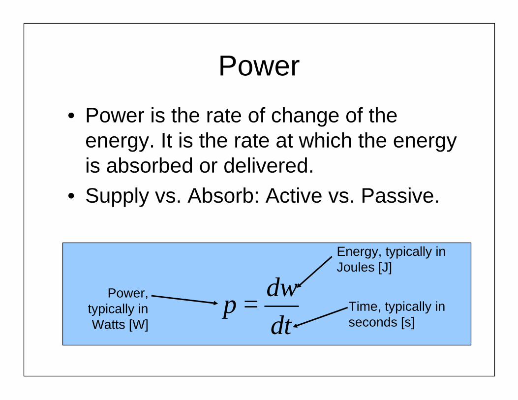
Power
• Power is the rate of change of the energy. It is the rate at which the energy is absorbed or delivered.
• Supply vs. Absorb: Active vs. Passive.
Power,typically inWatts [W]
Energy, typically in Joules [J]
Time, typically in seconds [s]
dwp
dt=

Power from Voltage and Current
Power can be found from the voltage and current, as shown below. Note that if voltage is given in [V], and current in [A], power will come out in [W].
dw dw dqp vi
dt dq dt= = × =

Sign Convention – Definition
• The passive sign convention is when the reference polarity for the current is in the direction of the reference voltage drop.
• The active sign convention is when the reference polarity for the current is in the direction of the reference voltage rise.
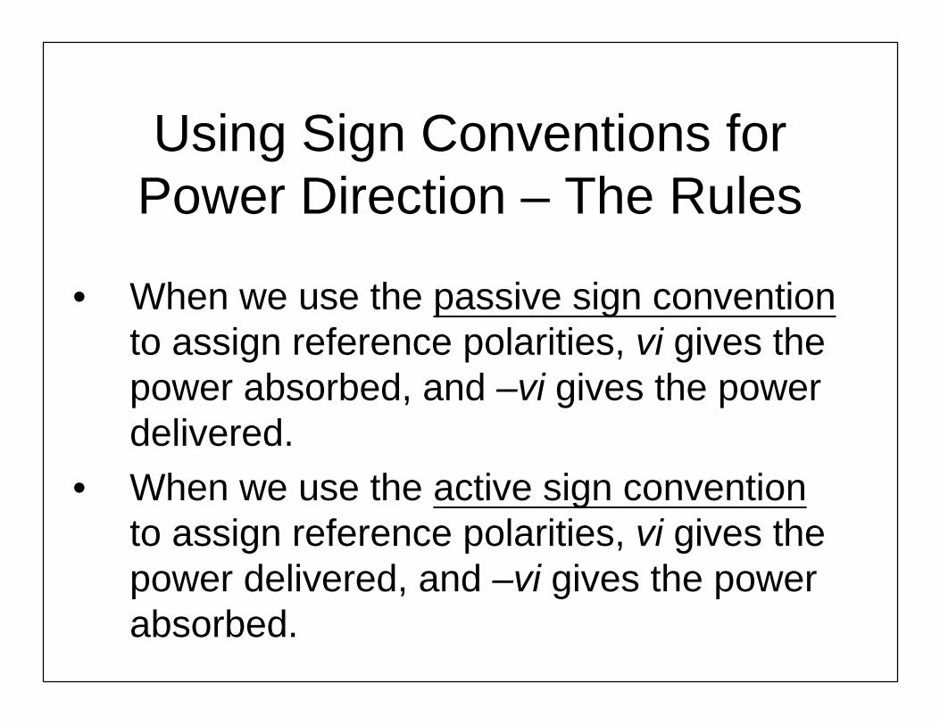
Using Sign Conventions for Power Direction – The Rules
• When we use the passive sign conventionto assign reference polarities, vi gives the power absorbed, and –vi gives the power delivered.
• When we use the active sign conventionto assign reference polarities, vi gives the power delivered, and –vi gives the power absorbed.

Example of Determining the Power with Polarity
SampleCircuit
iSvS
+
-
Passive Convention
Active Convention
Power absorbed
pabs = vi pabs = -vi
Power delivered
pdel = -vi pdel = vi
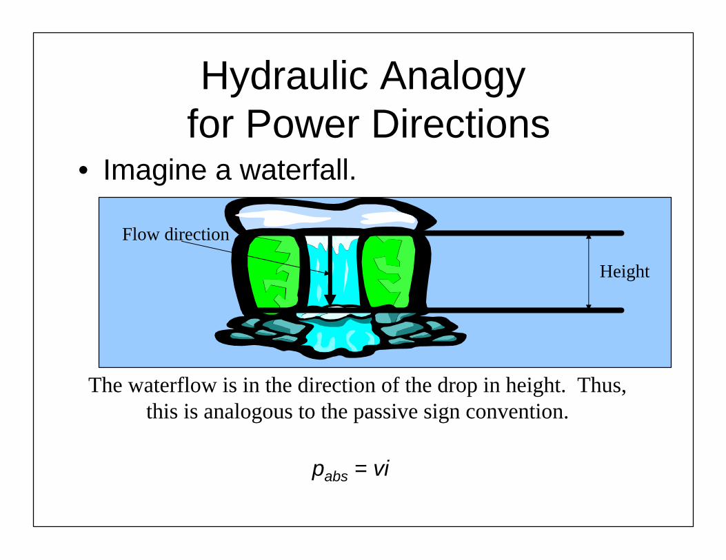
Hydraulic Analogyfor Power Directions
• Imagine a waterfall.
The waterflow is in the direction of the drop in height. Thus, this is analogous to the passive sign convention.
pabs = vi
Height
Flow direction
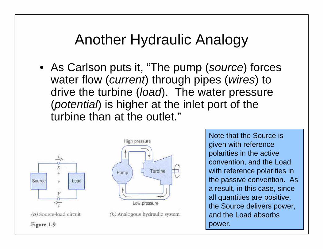
Another Hydraulic Analogy
• As Carlson puts it, “The pump (source) forces water flow (current) through pipes (wires) to drive the turbine (load). The water pressure (potential) is higher at the inlet port of the turbine than at the outlet.”
Note that the Source is given with reference polarities in the active convention, and the Load with reference polarities in the passive convention. As a result, in this case, since all quantities are positive, the Source delivers power, and the Load absorbs power.
Some Resistive Circuit Elements

Overview
• Independent voltage source and current source
• Resistors and Ohm’s Law• How to describe “behavior”of a circuit:
– v(t), i(t)– i-v curve (v-i curve)

Voltage Sources
• A voltage source is a two-terminal circuit element that maintains a voltage across its terminals.
• The voltage value is the defining characteristic.
• Any value of the current can go through the voltage source (including zero).

Current Sources
• A current source is a two-terminal circuit element that maintains a current through its terminals.
• The current value is the defining characteristic.
• Any voltage can be across the current source (including zero).

Ideal Sources
i-v curve (v-i curve)

Ohm’s Law and Resistors
• A (linear) resistor is a two terminal circuit element that has a constant ratio of the voltage across its terminals to the current through its terminals.
• Passive sign convention.
R
R
vR
i=Ohm’s law:

Lumped Circuits
• Lumped-parameter models: spatially distributed property is lumped entirely at one point.
• EM wavelength is much larger than dimensions of the circuit.
• Only lumped circuits are considered in this course.

Lumped vs. Distributed
• Lumped circuit:– electromagnetic wavelength >> largest
dimension of the circuit– the respective locations of circuit elements
are not important
• Distributed circuits– when the lumped approximation is not valid– examples: transmission lines (will be covered
in the EM class)

1.4 Kirchhoff’s Laws

Node
• Node: connection point of two or more circuit elements.
+
-vA
RC
RD
iB
RF
RE
+
-
vA
RC
RD
iB
RF
RE

KCL (Node)
• Charge is conserved and does not accumulate at a node.
• Kirchhoff's current law (KCL): The sum of the currents leaving any node equals the sum of the currents entering that node.
• Elements in series carry the same current. (Dual with KVL)
213 iii +=
0321 =−+ iiior

KCL (Supernode)
• Supernode: any closed region contains two or more nodes and the wires intersected by the boundary are only intersected once (closed surface).
• The algebraic sum of all currents into any supernode is zero.
04321043
021 =−−+
⇒=−−
=−+iiii
iixixiii
Node A
Node B
Supernode

Loop
• A loop is any path that goes from node to node, returns to the staring node and passing only once through each node.
+
-
vA
RC
RD
iB
RF
RE
vX
+
-
+
-
vA
RC
RD
iB
RF
RE
vX
+
-
+
-
vA
RC
RD
iB
RF
RE
vX
+
-
+
-
vA
RC
RD
iB
RF
RE
vX
+
-
+
-
vA
RC
RD
iB
RF
RE
vX
+
-

KVL (Loop)• Kirchoff's voltage law (KVL): the sum of voltage drop around a
loop is the sum of voltage rise.• The algebraic sum of all voltage drops around any loop
equals zero.• Elements in parallel have the same voltage across each one
of them. (Dual with KCL)

Example 1.7
• Determine the remaining unknown circuit variables.
m Ai B 5.0=
Vv CE 7=
VvVv
mAimAi
82
5.112
2
4
3
1
−====
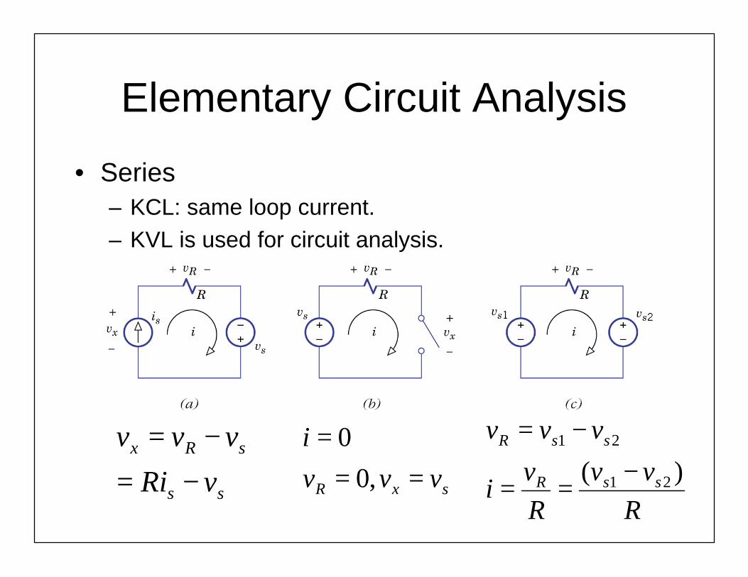
Elementary Circuit Analysis
• Series– KCL: same loop current.– KVL is used for circuit analysis.
ss
sRx
vRi
vvv
−=−=
sxR vvvi
===
,00
Rvv
Rv
i
vvv
ssR
ssR
)( 21
21
−==
−=

Elementary Circuit Analysis• Parallel
– KVL: same node voltage– KCL is used for circuit analysis
ss
sRx
iGv
iii
−=−=
sx
R
iii
== 0
RiiRiv
iii
ssR
ssR
)( 21
21
−==−=

Example 1.8
• Operate at vx=10V, ix=2.5A
• Supplied by 12V or 3A• A resistor is required• Find Rser and Rpar.
• Rser=(12-10)/2.5=0.8
• Rpar=10/0.5=20
Branch Variable Analysis
• Branch variable analysis: assign voltage or current associated with individual elements as immediate variables.

Example 1.9• Find is and the
power supplied by the sources.
• is =3+5+2=10A
• Total supplied power = pv+pi=-50+450 =400W
Absorbing -50WSupplying 450W
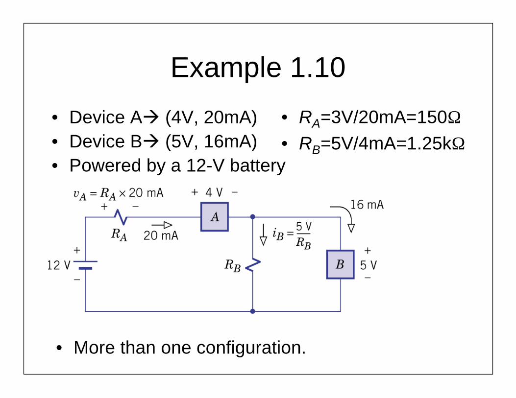
Example 1.10
• Device Aà (4V, 20mA)• Device Bà (5V, 16mA)• Powered by a 12-V battery
• More than one configuration.
• RA=3V/20mA=150Ω• RB=5V/4mA=1.25kΩ

Chapter 1: Problem Set
• 34, 37, 40, 47