1
Outer Riser Assembly Inner Riser Assembly THREADED PLUG & ADAPTOR Optional FINGER HOLE THUMB SCREW NOTCH INNER RISER PIPE not included VALVE BODY BUSHING Bushings are provided for PVC schedule 40x SDR-35 installations Building Sewer FLAPPER ASSEMBLY FLAPPER Heavy Duty Rated at 75 PSI OUTER RISER PIPE not included Extendable Backwater Valve 1 2 3 4 5 6 7 8 9 10 INSTALLATION INSTRUCTIONS Contact: RectorSeal ® 713-263-8001 800-231-3345 713-263-7577 800-441-0051 www.rectorseal.com P F W VALVE BODY Flow Building FLOW OUTER RISER PIPE SEWER LATERAL Outer Riser Installation At proper depth, install the Clean Check Valve Body between the building and the sewer lateral, with the “FLOW” arrow of the Valve Body pointing downstream away from the building. Rotate the Valve Body until the opening is facing directly upward. A level may be used across the top of the Valve Body to verify horizontal positioning. Cut the Outer Riser Pipe to the required length. Cement and insert while keeping the inside of the body clean of debris. CAUTION: Be certain that excess solvent cement has not impeded proper seating of the Flapper Assembly or the proper seating of the flapper sealing surface of the Valve Body. Inner Riser Installation Cut the Inner Riser Pipe to a length (3-1/2”) shorter than the Outer Riser Pipe. Cement the Flapper Assembly to one end of the Inner Riser Pipe. Cement the Upper Collar to the other end of the Inner Riser Pipe, while aligning the center of the Finger Hole with the center of the Flapper on the opposite end. When cement is dry, loosen the thumb screw in the Upper Collar and slide the Inner Riser Assembly – Flapper Assembly first – into the Outer Riser Assembly with the flat sealing side of the Flapper facing the inlet side of the Valve Body. Lower the Inner Riser Assembly into the seating area of the Valve Body, making certain that the Thumb Screw is inside the inside wall of the Outer Riser Pipe and NOT on the resting on the top edge. Seat the Flapper Assembly by rotating as necessary until it locks in place. Visually inspect that the Flapper Assembly is installed correctly. IMPORTANT: Prior to installation of the Threaded Adaptor & Plug (with the Inner Riser Assembly properly installed) cut a reference notch into the Outer Riser Pipe. This saw cut notch should be aligned with the molded Notch in the Upper Collar. For future removal, alignment of the notches will quickly indicate that the flapper is seated correctly. IMPORTANT: Tighten the ¼” Stainless Steel Thumb Screw until it seats snugly against the Inner Riser Pipe, fixing the Inner Riser Assembly in place. Cement the Threaded Adapter to the Outer Riser Pipe riser and screw the Threaded Plug into the Threaded Adapter to complete installation. Pre-Installation Slide Upper Collar through Outer Riser Pipe. If collar does not slide freely through pipe, check to see if pipe is “out-of-round”. If so, replace Outer Riser Pipe. Backwater valves require adequate drop between the flood rim of the lowest fixture and burial depth of the valve in order to function properly. We recommend a minimum slope of 1/4” per foot or as recommended by the UPC and IPC codes. Additional PVC bushings are enclosed for use if needed. Discard if not used. Parts not provided • Standard 8” or 6" ABS or PVC Outer Riser Pipe of re- quired length, and one 8" or 6" Threaded Adaptor & Plug (8" or 6" Outer Riser Pipe is determined by the Clean Check model to be used) • Standard 4” ABS or PVC Inner Riser Pipe of required length. CHECK ® CLEAN REFERENCE NOTCH See step 8 RectorSeal brand solvent cements are approved to meet manufacturer’s recommendations.

CLEAN CHECK - Newburgh Winwaternewburghwinwater.com/nww/submittals/sewer/Backwater Valves/(RS-2... · Outer Riser Assembly ... install the Clean Check Valve Body ... Riser Pipe. Cement

Embed Size (px)

Citation preview

Outer R

iser Assem

bly

Inner Riser A

ssembly

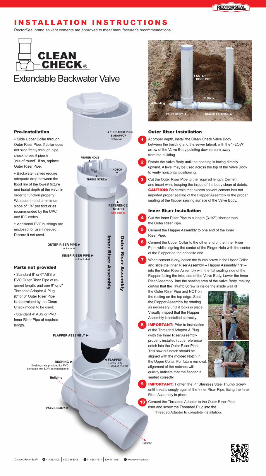
◄ tHREADED PLUG & ADAPtoR optional

finGER HoLE▼

▲tHUMB SCREW

notCH ▼

innER RiSER PiPE ► not included

VALVE BoDY ►

BUSHinG ► Bushings are provided for PVC schedule 40x SDR-35 installations

Building

Sewer

fLAPPER ASSEMBLY ►

◄ fLAPPER Heavy Duty

Rated at 75 PSI

oUtER RiSER PiPE ► not included

Extendable Backwater Valve

1

2

3

4

5

6

7

8

9

10

I N S TA L L AT I O N I N S T R U C T I O N S

Contact: RectorSeal® 713-263-8001 800-231-3345 713-263-7577 800-441-0051 www.rectorseal.comP F W

VALVE BoDY ▲

flow ►◄ Building

fLoW ►

◄ oUtER RiSER PiPE

SEWER LAtERAL ▲

Outer Riser Installation At proper depth, install the Clean Check Valve Body between the building and the sewer lateral, with the “FLOW” arrow of the Valve Body pointing downstream away from the building.

Rotate the Valve Body until the opening is facing directly upward. A level may be used across the top of the Valve Body to verify horizontal positioning.

Cut the Outer Riser Pipe to the required length. Cement and insert while keeping the inside of the body clean of debris. CAUTION: Be certain that excess solvent cement has not impeded proper seating of the Flapper Assembly or the proper seating of the flapper sealing surface of the Valve Body.

Inner Riser InstallationCut the Inner Riser Pipe to a length (3-1/2”) shorter than the Outer Riser Pipe.

Cement the Flapper Assembly to one end of the Inner Riser Pipe.

Cement the Upper Collar to the other end of the Inner Riser Pipe, while aligning the center of the Finger Hole with the center of the Flapper on the opposite end.

When cement is dry, loosen the thumb screw in the Upper Collar and slide the Inner Riser Assembly – Flapper Assembly first – into the Outer Riser Assembly with the flat sealing side of the Flapper facing the inlet side of the Valve Body. Lower the Inner Riser Assembly into the seating area of the Valve Body, making certain that the Thumb Screw is inside the inside wall of the Outer Riser Pipe and NOT onthe resting on the top edge. Seat the Flapper Assembly by rotating as necessary until it locks in place. Visually inspect that the Flapper Assembly is installed correctly.

IMPORTANT: Prior to installation of the Threaded Adaptor & Plug (with the Inner Riser Assembly properly installed) cut a reference notch into the Outer Riser Pipe. This saw cut notch should be aligned with the molded Notch in the Upper Collar. For future removal, alignment of the notches will quickly indicate that the flapper is seated correctly.

IMPORTANT: Tighten the ¼” Stainless Steel Thumb Screw until it seats snugly against the Inner Riser Pipe, fixing the Inner Riser Assembly in place.

Cement the Threaded Adapter to the Outer Riser Pipe riser and screw the Threaded Plug into the Threaded Adapter to complete installation.

Pre-Installation

• Slide Upper Collar through Outer Riser Pipe. If collar does not slide freely through pipe, check to see if pipe is “out-of-round”. If so, replace Outer Riser Pipe.

• Backwater valves require adequate drop between the flood rim of the lowest fixture and burial depth of the valve in order to function properly.We recommend a minimum slope of 1/4” per foot or as recommended by the UPC and IPC codes.

• Additional PVC bushings are enclosed for use if needed. Discard if not used.

Parts not provided • Standard 8” or 6" ABS or PVC Outer Riser Pipe of re-quired length, and one 8" or 6" Threaded Adaptor & Plug(8" or 6" Outer Riser Pipe is determined by the Clean Check model to be used)

• Standard 4” ABS or PVC Inner Riser Pipe of required length.

CHECK ®

CLEAN

EXTENDABLE BACKWATER VALVEMAINTENANCE GUIDE

▲ REfEREnCE

notCHSee step 8

RectorSeal brand solvent cements are approved to meet manufacturer’s recommendations.