Embed Size (px)
Citation preview

Clinical Guidelines for Dental Implant Treatment
A MANUAL OF THE SYSTEMosd 2001, Vol 12
Kari Luotio
K. L
uotio
- OS
FIX
IMPLA
NTS
- OS
D.
20
01 v
ol. 1
2


Published as vol. 12 in Oral Surgery Diagnosis 2001 Kuopio FINLAND
Printed: Oy Kotkan Kirjapaino Ab 2001
ISBN: 951-98037-1-8
Design: muotoari tmi
OSFIX International Ltd. Oy
P.O. BOX 14
FIN-47201 Elimäki
tel. + 358 5 779 7700
fax + 358 5 7797763
www.osfix.fi
Clinical Guidelines for Dental Implant Treatment
Edited by Kari Luotio
A MANUAL OF THE SYSTEM

FOREWORD:
Osfix - from philosophy to system
The main task of dental implantology is occlusal rehabilitation. We should call
the end product a prosthesis, whether it is removable or not. As described, a
prosthesis is a substitute for an organ or its function. At best, a patient should
be able to forget that they using a prothesis and its existence should in itself be
satisfying to them. If we can fulfil these criteria, we have given the patient a gift,
a gift which is one of the most important they will ever receive.
The field of dental implantology increased rapidly until the beginning of the
last decade. This is explained not only by the increasing level of dentists’
knowledge and skills, but also by the various national social security systems in
Central Europe and some Scandinavian countries. Today, these systems are less
effective as a result of economic depression. This has forced the development
of reasonable, simplified and rational dental implant systems such as the Osfix
system.
It is possible to describe dental implantology as controlled risk-taking, based
on skilled surgery in the jawbone, modern titanium fabrication and precision
dental laboratory manufacturing. This involves three obligatory conditions for
the implantologist: 1. A knowledge of anatomy; 2. the ability to handle tissues
such as the mucous membrane, muscles, nerves, veins, bones, extra oral tissues,
and even sinuses; and 3. the ability to assemble prefabricated titanium parts and
hand-made dental laboratory products. If any of these claims are not fulfilled,
the risk-taking is no longer controlled.
Anatomical hand books were written a long time ago, therefore the idea of this
book is not to teach surgical anatomy. However, repetitio est mater studiorum.
It is not a waste of time to consider applied implantological anatomy, because a
small misalignment of an implant may result in tremendous technical problems
between the bone surface and occlusion becoming apparent. It is impossible to
overstate the importance of the advice of experienced implantologists and the
enormous knowledge which is available in other implantological books.
It may be that surgeons are born, i.e. surgical capability is mainly inherent,
not the result of academic education. If the implantologist has “good hands”
the bone tissue also “feels good”. Some details in the Osfix system may be at
odds with general implantological faith and might contradict accepted “facts”.
However, when the results are of a top-level European standard, it is a time to
reconsider. The philosophy of Osfix is 10 years old, today Osfix is a system for
which more and more references are available - scientific and clinical.
Risto M.Kotilainen
DDS, PhD Professor (OMF-Surgery)
University of Kuopio, Finland

Professor Kotilainen has expressed his view that today, some implantological
truths might be collapsing as a result of technical advances. One of these
dogmas is the use of gold alloys in prosthetic frameworks, another is the need
for titanium angulated abutments and the third is the as-machined titanium
surface of the implant. The reality of competition between implant companies
has broken down the last; almost every company uses rough surfaced, i.e.
sandblasted, acid-etched or plasma-sprayed implants today. The second dogma
is now falling down because more and more companies are offering prosthetic
components which are an integrated part of the cast work and are in direct
contact with the implants. Moreover, the need for angulated parts may be
avoided with skilful working. The last dogma still stands. However, if the
implantologist does not wish to face that conflict, it is always possible to use
precious metal, i.e. gold prefabricated cast-on components, in the Osfix system
as well.
Author

INTRODUCTION OF THE AUTHORS:
List of authors in alphabetical order:
Ms. Hanhela, Marika: MSc - Editor, Part V
Ms. Hiedanpää, Heini: Artist - Drawings in Part I and III
Mr. Kotilainen, Risto: DDS, PhD, Prof. - Scientific review
Mr. Lappi, Timo: Dent. Tech., Production Manager - Part II, photographs in Part I
Mr. Luotio, Kari: DDS, PhD, Consultant Surgeon - Parts I and V, Senior Editor
Ms. Petrelius, Ulla: DDS - Operations in the clinical test
Ms. Poussa, Tuija: MSc - Statistical consultations
Mr. Ryhänen, Janne: DDS - Operations in the clinical test
Mr. Smith, David: - Language editing
Ms. Stenberg, Tuula: MSc, PhD - Coating study
Ms. Turunen, Jaana: Dental Hygienist. - Part III and follow-up study
Mr. Vesanen, Hannu: DDS - Animal study
Ms. Vuori, Tiina: MSc - Linguistic consultation
The author would like to thank the above mentioned for their assistance in the
project to develop a new implant system. In addition, the author extends his
gratitude to everyone else who has participated in the process: performing their
graduation work for the company, colleagues giving professional advice and
financial support to the project.

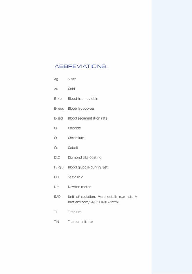
ABBREVIATIONS:
Ag Silver
Au Gold
B-Hb Blood haemoglobin
B-leuc Bloob leucocytes
B-sed Blood sedimentation rate
Cl Chloride
Cr Chromium
Co Cobolt
DLC Diamond Like Coating
fB-glu Blood glucose during fast
HCl Saltic acid
Nm Newton meter
RAD Unit of radiation. More details e.g: http://
bartleby.com/64/ C004/037.html
Ti Titanium
TiN Titanium nitrate
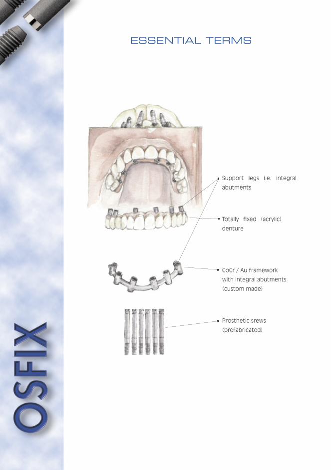
ESSENTIAL TERMS
Support legs i.e. integral
abutments
Totally fixed (acrylic)
denture
CoCr / Au framework
with integral abutments
(custom made)
Prosthetic srews
(prefabricated)
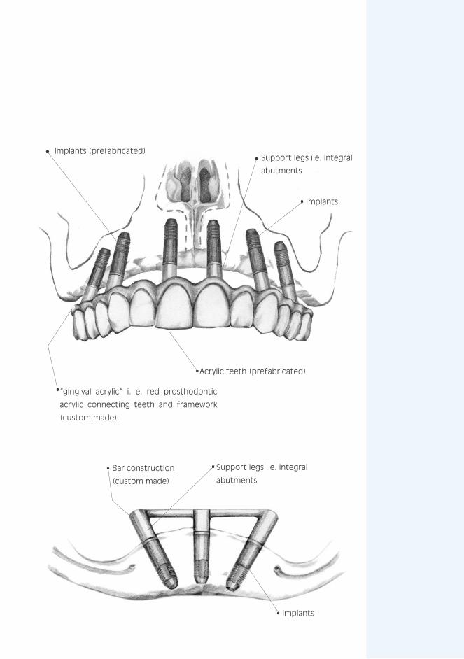
Bar construction
(custom made)
Implants (prefabricated)
Acrylic teeth (prefabricated)
Support legs i.e. integral
abutments
Support legs i.e. integral
abutments
“gingival acrylic” i. e. red prosthodontic
acrylic connecting teeth and framework
(custom made).
Implants
Implants


MAIN MENU:
FOREWORD
INTRODUCTION OF THE AUTHORS
ABBREVIATIONS
ESSENTIAL TERMS
PART I: Clinical........................................................... 9
PART II: Laboratory................................................... 85
PART III: Hygiene ..................................................... 101
PART IV: Sedation.................................................... 115
PART V: Studies ..................................................... 145
KEYWORDS ............................................................. 203


PART I
CL IN ICAL
Clinical guidelines
for surgery
and prosthodontics

Page - 10

PART I CONTENTS:
1. INTRODUCTION
1.1 The Osfix Dental Implant System - A brief review of literature and presentation of the products.......15
1.1.1 Surgery .....................................................15
1.1.2 The prosthetic structure ............................16
1.1.3 Cobalt chrome as frame material .................16
1.1.4 Expected success rate ...............................16
1.1.5 Special techniques in surgery ......................17
1.1.6 Presentation of the product ........................18
1.2 The structure of Osfix and Biosfix implants.........19
1.2.1 Osfix .........................................................19
1.2.2 BiOsfix.......................................................20
1.3 The prosthetic superstructure..........................23
1.3.1 Totally osteointegrated prostheses .............23
1.3.2 Prostheses supported with osteointegration 24
1.4 Patient satisfaction .........................................24
1.5 Main solutions .................................................25
1.6 Components ....................................................26
2. OSTEOINTEGRATION AND TITANIUM IMPLANTS.........30
2.1 Osteointegration .............................................30
2.2 Rejection of foreign materials............................33
2.3 Bone tissue .....................................................34
2.4 Healing of bone after a trauma..........................35
2.5 Epithelial attachment .......................................35
2.6 Implants..........................................................35
2.6.1 Subdivision.................................................35
2.6.2 The osteointegrating titanium implants used 35
3. PLANNING THE TREATMENT
3.1 Indications.......................................................36
3.2 Contraindications.............................................36
3.3 Diagnosis and examinations needed ...................38

Page - 12

3.4 Placing the implants.........................................41
3.4.1 Maxilla.......................................................41
3.4.2 Mandible ....................................................42
3.4.3 The mutual placing of implants .....................46
3.4.4 The superstructure ....................................47
3.4.5 Partial prostheses or short bridges .............48
3.4.6 Grading of bone for design construction .......48
4. THE PROCEDURES ................................................50
4.1 Surgery - primary operations ............................50
4.1.1 Aseptic and other preparations ...................50
4.1.2 Medication.................................................54
4.1.3 The operation .............................................54
4.1.4 Postoperative treatment of the patient........59
4.2 Secondary operations.......................................59
4.2.1 Impression phase .......................................59
4.2.2 Mounting the prosthetics ...........................61
4.2.3 Service of fixed prosthesis ..........................62
5. EXAMPLES
5.1 Biosfix ............................................................63
5.2 Standard fixing bar ..........................................69
5.3 Totally fixed prosthesis ....................................73
5.4 Combination ...................................................76
5.5 Aesthetic problems .........................................79
6. FAILURES ..............................................................81
6.1 Loss of Implants ..............................................81
6.2 Mistakes in structural design ...........................81
6.3 Mistakes in fabrication .....................................81
6.4 Patient related factors.....................................81

Page - 14
Page - 15
YOU ARE IN:
PART I: Clinical
1. INTRODUCTION
1.1 The Osfix Dental Implant System - A brief review of literature and presentation of the products
1.2 The Structure of Osfix and Biosfix implants
1.3 The Prosthetic superstructure
1.4 Patient satisfaction
1.5 Main Solutions
1.6 Components
2. OSTEOINTEGRATION AND TITANIUM IMPLANTS
3. PLANNING THE TREATMENT
4. THE PROCEDURES
5. EXAMPLES
6. FAILURES
PART II: Laboratory
PART III: Hygiene
PART IV: Sedation
PART V: Studies
A factor important to the success of
the implant is the unstressed recovery
allowed by two-phase surgery. The
result of the primary recovery after
implantation is full osteointegration,
in which the implant is joined, without
any connective tissue layer, directly to
the bone. It should also be mentioned
in this context that the implant is then
completely surrounded with compact
bone which will remain around the
implant when it is subject to strain
at a later stage. This phenomenon
has been studied by Kraut et al.
(1991) by the use of tension tests.
They discovered that the mechanical
immobility of the implant improved
continuously, starting 2 weeks after
surgery and continuing until 24 weeks.
This finding clearly supports a half-year
recovery period before subjecting the
implant to strain. Their research also
indicated that the extraction forces
are considerably greater from the
mandible than from the maxilla. As
a contrast, no correlation with the
primary stability during the procedure
could be found.
The Osfix system allows the use of an
internally cooled drilling system during
primary surgery. The relevance of
internal cooling has been researched
by Haider et al. (1993) in a histological
study based on the contact percentage
of new bone grown onto the surface
of the implant. In this work, external
cooling showed better results in the
initial phase of the drilling when the
bit forces were concentrated on the
surface bone, but the advantages of
internal cooling are apparent when
the drill moves deeper into compact
bone. This phenomenon has also
been thermographically studied, even
though such tests do not necessarily
hold any implications for the clinical
importance of these phenomena. The
test results showed the most
significant differences when no cooling
was used (Watanabe et al. 1992).
1. INTRODUCTION
1.1 The Osfix Dental Implant System - A brief review of literature and presentation of the products
1.1.1 Surgery
References at the end of Part I
Page - 16
The importance of prosthetic
constructions for the success of
implants, mentioned above, has been
studied by Hertel and Kalk (1993) using
a group of 81 patients: the effect
of the distance between implants was
compared with radiologically observed
loss of bone. The most significant
loss was found amongst overdenture
patients with a supporting bar fixed on
two implants in a toothless mandible.
The conclusion was reached that the
optimal placing of implants is ca.
25 mm distance apart. Implant losses
caused by a poor structure of the
prosthesis were rare, and whenever an
implant was lost, a prevalent factor
was the patient’s ability and will to
care for his oral hygiene. There are
also some infection factors, such as
Kellett and Smith’s (1991) finding that
the loss of an implant may follow a
specific infection with a ecosystem
and bacterial flora which is often
seen in connection with periodontal
illnesses.
1.1.2 The prosthetic structure
1.1.3 Cobalt chrome as frame material
It is general practice that an implant
frame is made of gold alloy but,
mainly for reasons of economy, cobalt
chrome alloy is a promising material
for the same purpose. Cobalt chrome
alloy is a material commonly used
for other dental prostheses and its
properties are well-known by both
dentists and dental technicians. One
of the disadvantages of cobalt chrome
alloy is its hardness, which makes
the material difficult to handle in a
dental laboratory. Eventual allergenic
reactions to cobalt chrome should also
be taken into consideration, although
they are extremely rare. All structures
should be designed to enable the
removal of the cobalt chrome alloy
components from implant and dental
structures. According to some studies,
cobalt chrome alloy components may
dissolve in oral conditions (Stenberg
1982, Moberg 1985). Galvanous
corrosion has been claimed to cause
loss of bone around the implant
(Adell et al. 1981, Lemons 1988, Geis-
Gerstorfer et al. 1989). The clinical
follow-up of implant prostheses does
not, however, support this claim
(Hulterström and Nilsson 1994, Luotio
1997), but indicates that the loss of
bone is at a similar level as that for
gold-based structures (Albrektsson et
al. 1986, Cox and Zarb 1987).
1.1.4 Expected success rate
The success rates of implants have,
over the years, become quite clearly
defined. Scientific follow-up studies
on implants with a roughened surface
structure hold a reasonably good
promise for the success of the
treatment. Fugatsotto et al. (1993)
followed 2,023 implants placed into
a total of 974 patients. All prosthetic
structures were represented from
single tooth implants to full dentures
completely fitted to the bone, and full
prostheses supported with a bar. The
cumulative success rate at the end of

Page - 17
YOU ARE IN:the 5 year follow-up study was 93 % for
the maxilla and 96 % for the mandible.
A study by Babbush and Shimura (1993)
followed 1,059 implants placed in a
total of 322 patients; the final success
rate in a 5 year follow-up was 96 %.
A division of success rates between
jaws gave a rate of 92 % for the
maxilla and 99 % for the mandible.
Thus the primary success rate of the
implantation process was good: of
more than 1,000 implants, only 9
were lost at secondary surgery due to
inadequate integration. The remaining
28 implants were lost during the 5 year
follow-up period. This study confirmed
the implantologically accepted fact
that the longer and wider the implant,
the better the result.
1.1.5 Special techniques in surgery
Special techniques in implantology are
described, to some extent, in the
literature. The common factor in
these techniques seems to be the
use of various films to direct
ossification, and the potential of
hydroxyl apatite. Implants have also
been used in immediate implantations
and expansions of the crista, in which
missing bone areas are filled with
porous hydroxyl apatite and covered
with films that enhance ossification
(Novaes and Novaes 1992, Ettinger et
al. 1993), as well as maxillary sinus
transfer operations. In this process,
a hole is carefully made in the bony
wall of the sinus, without breaking the
mucosa. The mucosa on the base of
the sinus is lifted with a bent periosteal
elevator from the future implantation
site, which enables direct visibility
when drilling the holes through the
base of the sinus. The bony drilling
waste is collected and finally, together
with venal blood and corallic hydroxyl
apatite, it is placed around the implants
and the sinus lift cavity (Luotio,
Petrelius 1994). All these methods
remain highly experimental and very
little scientific material is available
thereon. Thus a general application
is not yet justified and, for the time
being, Osfix implants should not be
used in experimental surgery.
Similar conditions apply to the use of
some new cleansing methods such as
the air-abrasive equipment developed
to cleanse transmucosal extensions
and infected implant surfaces. Even
though studies have shown that such
equipment does not, as such, impair
the surface of the implant or make it
more attractive to bacteria (Barnes et
al. 1991), at present the use of these
systems involves rather high risks and
possibilities for complications (Van de
Velde et al. 1991).
PART I: Clinical
1. INTRODUCTION
1.1 The Osfix Dental Implant System - A brief review of literature and presentation of the products
1.2 The Structure of Osfix and Biosfix implants
1.3 The Prosthetic superstructure
1.4 Patient satisfaction
1.5 Main Solutions
1.6 Components
2. OSTEOINTEGRATION AND TITANIUM IMPLANTS
3. PLANNING THE TREATMENT
4. THE PROCEDURES
5. EXAMPLES
6. FAILURES
PART II: Laboratory
PART III: Hygiene
PART IV: Sedation
PART V: Studies

Page - 18
The Osfix implant is a cylindrical implant
with an apical screw portion for
improved primary stability. The implant
has an internal hexagonal structure for
tightening during surgery. The implant
is made of grade 2 pure titanium and
the implant surface is mechanically
coarsened. The upper section of the
implant is polished. The length of
the implants are 11.0 and 13.5 mm
and the outer diameter 3.75 mm. The
Osfix implant is primarily designed for
use in bar retained over-dentures in
the lower jaw in totally edentulous
patients, but many other indications
are valid, as described later.
Osfix implants are products made
by Osfix International Ltd Oy. They
are friction fastened, mechanically
roughened implants in which primary
stability has been increased with a
threaded tip. The Osfix implant is
a bridge implant that enables the
construction of dolder-type bar
structures to support the prosthesis.
The main differences between the
Osfix implant and other existing
implants is the simplicity of the
structure, the low component count
and the low price of the product.
The base of the Osfix implant is
formed by the actual implant cylinder,
which is fitted to the jawbone. This
is covered during the first operation
with a primary screw. In a subsequent
operation, the screw is removed from
the implant cylinder and replaced by
an impression post, which is fitted into
place with occlusal screws included
in the set. The impression posts are
then delivered to a dental laboratory
where they are cast into part of the
superstructure.
1.1.6 Presentation of the product
a minimun of three OSFIX implants are
needed for each frame structure
Page - 19
YOU ARE IN:
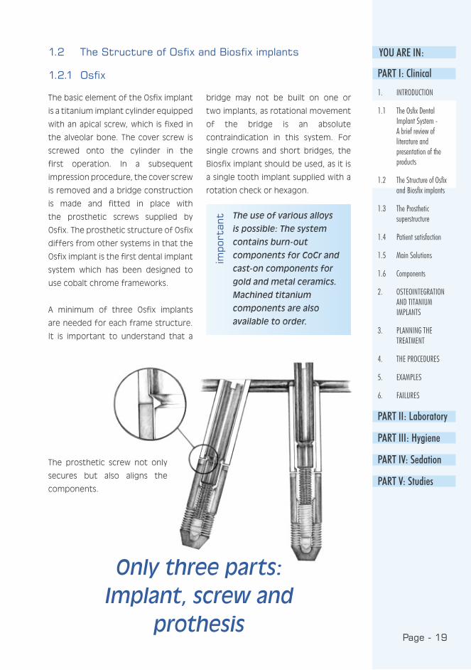
The basic element of the Osfix implant
is a titanium implant cylinder equipped
with an apical screw, which is fixed in
the alveolar bone. The cover screw is
screwed onto the cylinder in the
first operation. In a subsequent
impression procedure, the cover screw
is removed and a bridge construction
is made and fitted in place with
the prosthetic screws supplied by
Osfix. The prosthetic structure of Osfix
differs from other systems in that the
Osfix implant is the first dental implant
system which has been designed to
use cobalt chrome frameworks.
A minimum of three Osfix implants
are needed for each frame structure.
It is important to understand that a
bridge may not be built on one or
two implants, as rotational movement
of the bridge is an absolute
contraindication in this system. For
single crowns and short bridges, the
Biosfix implant should be used, as it is
a single tooth implant supplied with a
rotation check or hexagon.
The use of various alloys
is possible: The system
contains burn-out
components for CoCr and
cast-on components for
gold and metal ceramics.
Machined titanium
components are also
available to order.
1.2 The Structure of Osfix and Biosfix implants
1.2.1 Osfix
impo
rtan
t
The prosthetic screw not only
secures but also aligns the
components.
PART I: Clinical
1. INTRODUCTION
1.1 The Osfix Dental Implant System - A brief review of literature and presentation of the products
1.2 The Structure of Osfix and Biosfix implants
1.3 The Prosthetic superstructure
1.4 Patient satisfaction
1.5 Main Solutions
1.6 Components
2. OSTEOINTEGRATION AND TITANIUM IMPLANTS
3. PLANNING THE TREATMENT
4. THE PROCEDURES
5. EXAMPLES
6. FAILURES
PART II: Laboratory
PART III: Hygiene
PART IV: Sedation
PART V: Studies
Only three parts: Implant, screw and
prothesis
Page - 20
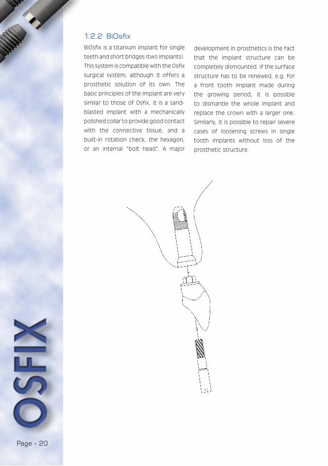
BiOsfix is a titanium implant for single
teeth and short bridges (two implants).
This system is compatible with the Osfix
surgical system, although it offers a
prosthetic solution of its own. The
basic principles of the implant are very
similar to those of Osfix, it is a sand-
blasted implant with a mechanically
polished collar to provide good contact
with the connective tissue, and a
built-in rotation check, the hexagon,
or an internal “bolt head”. A major
1.2.2 BiOsfix
development in prosthetics is the fact
that the implant structure can be
completely dismounted. If the surface
structure has to be renewed, e.g. for
a front tooth implant made during
the growing period, it is possible
to dismantle the whole implant and
replace the crown with a larger one.
Similarly, it is possible to repair severe
cases of loosening screws in single
tooth implants without loss of the
prosthetic structure.
Page - 21
YOU ARE IN:im
port
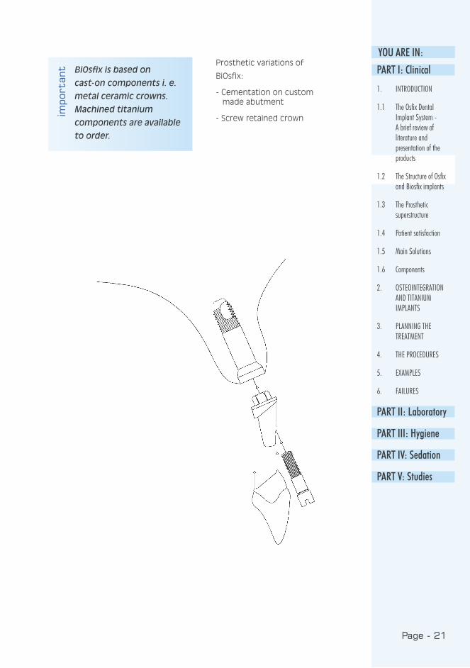
ant BiOsfix is based on
cast-on components i. e.
metal ceramic crowns.
Machined titanium
components are available
to order.
Prosthetic variations of
BiOsfix:
- Cementation on custom made abutment
- Screw retained crown
PART I: Clinical
1. INTRODUCTION
1.1 The Osfix Dental Implant System - A brief review of literature and presentation of the products
1.2 The Structure of Osfix and Biosfix implants
1.3 The Prosthetic superstructure
1.4 Patient satisfaction
1.5 Main Solutions
1.6 Components
2. OSTEOINTEGRATION AND TITANIUM IMPLANTS
3. PLANNING THE TREATMENT
4. THE PROCEDURES
5. EXAMPLES
6. FAILURES
PART II: Laboratory
PART III: Hygiene
PART IV: Sedation
PART V: Studies

Page - 22
Only three parts: Implant, crown
and screw

Page - 23
YOU ARE IN:
In the Osfix system, these are
constructed on a maximum of five or
six implants in the bone, fitted with a
metal framed, acrylated full denture:
a chrome cobalt frame full denture
with acrylic teeth is fitted on the
implants. In some cases, the chrome
cobalt frame also forms the lingual
or palatal surface of the bridgework,
but often it forms only the base that
connects the implants. On or around
this chrome cobalt structure, red
acrylic replaces the resorbed alveolar
ridge and gums, fitted with ordinary
plastic prostheses. A hole for each
implant passes through the whole
structure. The prosthesis is held in
place with six screws. When the
prosthesis is finally taken into use,
the screw openings are covered with
composite filling material.
This method enables full stability and
complete occlusion forces for the
prosthesis, although problems such as
air leaks may occur, especially in
the maxilla between the palate and
the prosthesis, or aesthetic problems
due to transmucosal metal extensions
in cases of incomplete lip-closure.
Visual or phonetic compromises that
complicate cleaning are often needed
in the maxilla.
Due to anatomic limitations, the
implants often need to be focused
anteriorically. A fully osteointegrated
prosthesis with a metal frame structure
can take a cantilever in the maxilla up
to 10 mm, and in the mandible up to
20 mm. With this kind of prosthesis,
the occlusion forces fully correspond
to those of natural teeth, whereas
the occlusion forces of an ordinary
prosthesis are only 1/4 - 1/5 those of
natural teeth. Totally osteointegrated
prostheses may also be partial
prostheses fitted on three, four or
even five implants in an edentulous
rear or middle area. The structure
of these either corresponds to the
previous prosthesis, or is made of
composite and metal frame. Ceramics
are being tested in the Osfix system
but are not yet in clinical use.
1.3 The Prosthetic superstructure
1.3.1 Totally osteointegrated prostheses PART I: Clinical
1. INTRODUCTION
1.1 The Osfix Dental Implant System - A brief review of literature and presentation of the products
1.2 The Structure of Osfix and Biosfix implants
1.3 The Prosthetic superstructure
1.4 Patient satisfaction
1.5 Main Solutions
1.6 Components
2. OSTEOINTEGRATION AND TITANIUM IMPLANTS
3. PLANNING THE TREATMENT
4. THE PROCEDURES
5. EXAMPLES
6. FAILURES
PART II: Laboratory
PART III: Hygiene
PART IV: Sedation
PART V: Studies
Page - 24
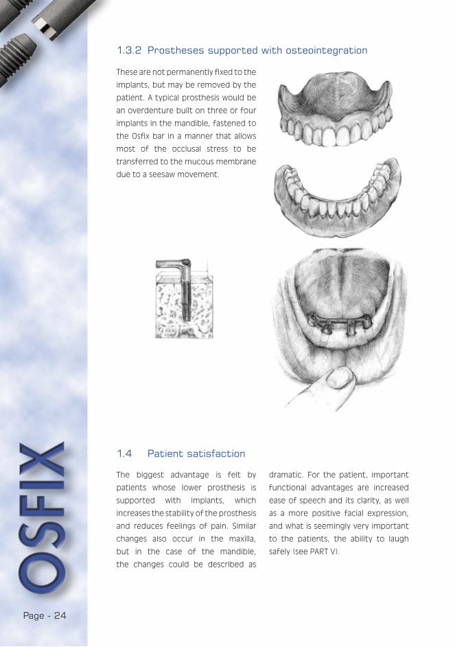
These are not permanently fixed to the
implants, but may be removed by the
patient. A typical prosthesis would be
an overdenture built on three or four
implants in the mandible, fastened to
the Osfix bar in a manner that allows
most of the occlusal stress to be
transferred to the mucous membrane
due to a seesaw movement.
The biggest advantage is felt by
patients whose lower prosthesis is
supported with implants, which
increases the stability of the prosthesis
and reduces feelings of pain. Similar
changes also occur in the maxilla,
but in the case of the mandible,
the changes could be described as
1.3.2 Prostheses supported with osteointegration
1.4 Patient satisfaction
dramatic. For the patient, important
functional advantages are increased
ease of speech and its clarity, as well
as a more positive facial expression,
and what is seemingly very important
to the patients, the ability to laugh
safely (see PART V).
Page - 25
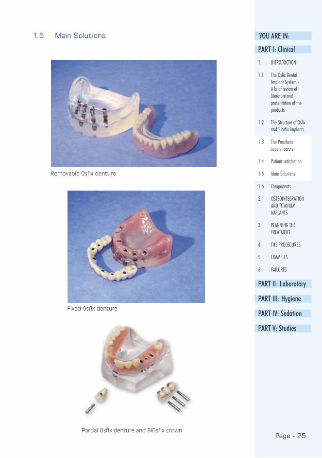
YOU ARE IN:1.5 Main Solutions
Removable Osfix denture
Fixed Osfix denture
Partial Osfix denture and BiOsfix crown
PART I: Clinical
1. INTRODUCTION
1.1 The Osfix Dental Implant System - A brief review of literature and presentation of the products
1.2 The Structure of Osfix and Biosfix implants
1.3 The Prosthetic superstructure
1.4 Patient satisfaction
1.5 Main Solutions
1.6 Components
2. OSTEOINTEGRATION AND TITANIUM IMPLANTS
3. PLANNING THE TREATMENT
4. THE PROCEDURES
5. EXAMPLES
6. FAILURES
PART II: Laboratory
PART III: Hygiene
PART IV: Sedation
PART V: Studies

Page - 26
1.6 Components
OSFIX implants:
• ø 3.75 mm
• Lengths: 11 mm and 13.5 mm
OSFIX Cover screws:
• Lengths: 0.5 mm and 1.5 mm
OSFIX Healing posts:
• Lengths: 3 mm, 4.5 mm, 6 mm and 7.5 mm
OSFIX Impression posts:
• wide, narrow, long
OSFIX Laboratory components:
• OSFIX Prosthetic screw,
• OSFIX Implant analogue
• OSFIX TM Extension burn-out
• OSFIX TM Extension cast-on
OSFIX adaptation drills
• ø 2.8 mm
• ø 2.6 mm
OSFIX Components
scale 3:2

Page - 27
YOU ARE IN:
BiOsfix implants:
• ø 4.2 mm and 5.0 mm
• Lengths: 11 mm, 13.5 mm and
16 mm
BiOsfix healing posts:
• ø 4.2 mm and 5.0 mm
• Lengths: 3.4 mm and 4.5 mm
BiOsfix Prosthetic kit Hexagon
• ø 4.2 mm and 5.0 mm
BiOsfix Implant analogues:
• ø 4.2 mm and 5.0 mm
BiOsfix Prosthetic screw
BiOsfix Copyposts:
• ø 4.2 mm and 5.0 mm
PART I: Clinical
1. INTRODUCTION
1.1 The Osfix Dental Implant System - A brief review of literature and presentation of the products
1.2 The Structure of Osfix and Biosfix implants
1.3 The Prosthetic superstructure
1.4 Patient satisfaction
1.5 Main Solutions
1.6 Components
2. OSTEOINTEGRATION AND TITANIUM IMPLANTS
3. PLANNING THE TREATMENT
4. THE PROCEDURES
5. EXAMPLES
6. FAILURES
PART II: Laboratory
PART III: Hygiene
PART IV: Sedation
PART V: Studies
BiOsfix Components
scale 3:2 scale 3:2

Page - 28
STEP-DRILL L2
OSFIX and BiOsfix Drills
scale 3:2
PILOT-DRILL
STEP-DRILL L6
STEP-DRILL S2
STEP-DRILL S6
counter-sink 5.0 mm
counter-sink 4.2 mm
twist drill 3.3 mm
twist drill 3.7 mm
Page - 29
YOU ARE IN:
PART I: Clinical
1. INTRODUCTION
1.1 The Osfix Dental Implant System - A brief review of literature and presentation of the products
1.2 The Structure of Osfix and Biosfix implants
1.3 The Prosthetic superstructure
1.4 Patient satisfaction
1.5 Main Solutions
1.6 Components
2. OSTEOINTEGRATION AND TITANIUM IMPLANTS
3. PLANNING THE TREATMENT
4. THE PROCEDURES
5. EXAMPLES
6. FAILURES
PART II: Laboratory
PART III: Hygiene
PART IV: Sedation
PART V: Studies
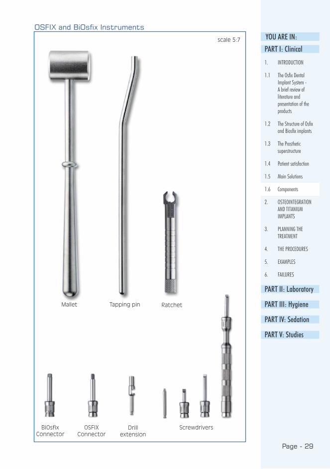
OSFIX and BiOsfix Instruments
RatchetTapping pinMallet
OSFIX Connector
ScrewdriversBiOsfix Connector
scale 5:7
Drill extension
Page - 30
Osteointegration is defined as the
direct contact of the implant with
the bone, without any soft-tissue layer
between. Titanium has been proven
to be the best material for implants,
as its osteointegration with stands a
force of over 100 kg. Even with this
force, the implant is not loosened, but
is broken off the bone.
Early research and actual development
work in osteointegrated implantology
was made at the turn of the 60s
and 70s, with commercial production
beginning in the 70s. During the 1980s,
many scientific symposia were held on
implantology, and the first temporary
approvals for titanium implants were
granted by the ADA. Implants began
to be placed in patients in meaningful
quantities at the beginning of the 90s,
at which time the development of the
Osfix implant also began. The Osfix
implant acquired sales permission for
the whole European Union in 1998,
when the quality assurance system in
production and clinical studies were
finalised.
2. OSTEOINTEGRATION AND TITANIUM IMPLANTS
2.1 Osteointegration
Page - 31
YOU ARE IN:
1. Grade 2 titanium of over 99 %
purity.
2. An oxide layer forms on the
titanium surface to which the
glyco-protein layer will attach and
later calcify.
3. The shape of the implant
distributes the occlusion stress
evenly to the bone. A triple surface
increase has been created in the
Osfix implant: the apical screw, the
micro screw of the stem and the
sand blasting on the surface of the
implant multiply its surface area.
4. The use of the correct (internal)
cooling during preparation. The
temperature in the preparation
area must not exceed 40 degrees
Celsius, and the rotation speed of
the drill must be below 2,000 rpm.
5. Two-phase surgery that allows
osteointegration without
disturbance; the implant
structures will be subjected to
strain only after the proper
osteointegration period of 3-6
months.
6. High asepsis in procedures.
7. The formation of a proper epithelial
integration in the second phase
Key factors in osteointegration
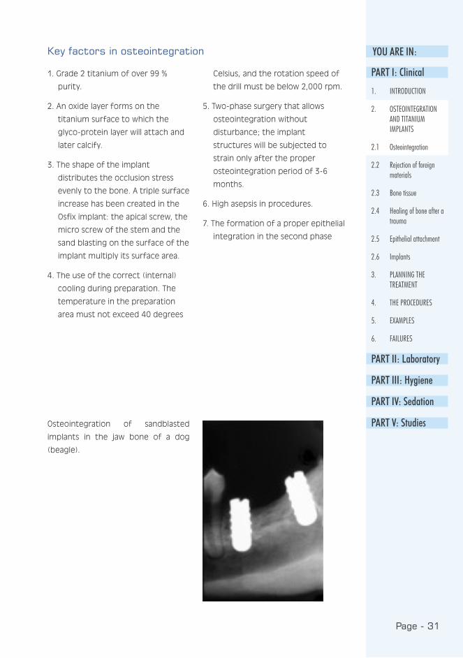
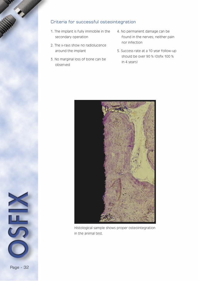
Osteointegration of sandblasted
implants in the jaw bone of a dog
(beagle).
PART I: Clinical
1. INTRODUCTION
2. OSTEOINTEGRATION AND TITANIUM IMPLANTS
2.1 Osteointegration
2.2 Rejection of foreign materials
2.3 Bone tissue
2.4 Healing of bone after a trauma
2.5 Epithelial attachment
2.6 Implants
3. PLANNING THE TREATMENT
4. THE PROCEDURES
5. EXAMPLES
6. FAILURES
PART II: Laboratory
PART III: Hygiene
PART IV: Sedation
PART V: Studies
Page - 32
1. The implant is fully immobile in the
secondary operation
2. The x-rays show no radiolucence
around the implant
3. No marginal loss of bone can be
observed
4. No permanent damage can be
found in the nerves; neither pain
nor infection
5. Success rate at a 10 year follow-up
should be over 90 % (Osfix 100 %
in 4 years)
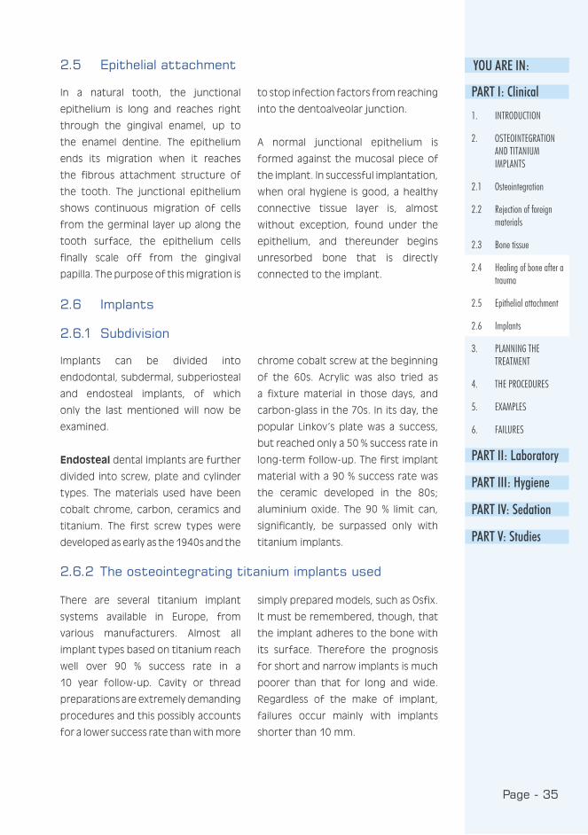
Criteria for successful osteointegration
Histological sample shows proper osteointegration
in the animal test.
Page - 33
YOU ARE IN:
The antigen-antibody reaction will
reveal any alien proteins found in the
living system. Corroding metal ions
will form complexes with the system’s
own proteins that are recognised
as antigenes. Therefore, titanium
implants must be kept clear of any
saliva or foreign metal contamination.
The package efficiently protects the
Osfix implant until the very moment
it is placed in the bone, whilst the
cylindrical primary insertion gives
protection against contamination
during the procedure.
Connective tissue organisation or
encapsulation means that foreign
material in the system will be
surrounded with connective tissue. The
thickness of the capsule will depend on
the material causing the reaction. With
the exception of titanium, practically
all materials are encapsulated in the
system. The movement of foreign
material is known to enhance the
capsulation around it, therefore the
primary fixation of the implant is
extremely important.
2.2 Rejection of foreign materials
2.3 Bone tissue
Bone is structurally divided into
compact and spongious bone, or
dense and cancellous bone; chemically
into organic and inorganic bone, each
of which amount to about 40 % of
the bone. The organic part consists
of collagen, glycosaminoglycans and
osteonectin. The inorganic part is
almost entirely made up of hydroxyl
apatite.
The inside of the bone tissue is
cancellous bone formed by thin bony
lamellae. This trabecular architecture
makes the structure of the bone lighter
whilst maintaining its strength. This
part of the bone contains the vascular
system while the dense bone carries
no blood vessels. On the surface of the
dense bone is the biologically active
cell layer of the bone, made up of
osteoblasts and osteoclasts. Their task
is to form new bone in the event of
injuries. The outermost layer is the
periosteum which is attached to the
bone by ligaments.
The function of the bone is to act
both as a supportive structure and
as a store for calcium. The exchange
of calcium between blood and bone
tissue is many tenfold compared to
the normal calcium intake from food.
Most of the calcium stored in the
skeletal structure is firmly bound in
the bone and balanced hormonally by
parathormone and calcitonin.
PART I: Clinical
1. INTRODUCTION
2. OSTEOINTEGRATION AND TITANIUM IMPLANTS
2.1 Osteointegration
2.2 Rejection of foreign materials
2.3 Bone tissue
2.4 Healing of bone after a trauma
2.5 Epithelial attachment
2.6 Implants
3. PLANNING THE TREATMENT
4. THE PROCEDURES
5. EXAMPLES
6. FAILURES
PART II: Laboratory
PART III: Hygiene
PART IV: Sedation
PART V: Studies
Page - 34
Primary healing: The bone heals after
a trauma when the fracture is clean
and full fixation is obtained. Blood
coagulates in the area with extensive
phagocytic activity during the first few
days. Thereafter, a procallus is formed
and great numbers of fibroblasts can
be observed microscopically. When the
connective tissue has become dense it
is referred to as callus. This is where the
first osteoblasts appear. Following this,
maturation occurs or the osteogenic
fibres in the callus begin to calcify.
Compact bone is formed initially, and
later it is organised into compact and
spongy bone. Thus, the normal primary
healing of the bone has taken place.
Secondary healing: Secondary healing
is found in bone in cases of large,
impure and comminuted fractures. No
stability is reached and the situation
is often complicated by infection.
Granulation tissue and extensive
infection forms in the area. This is
followed by delayed healing and a
vicious circle in which the infected
granulation tissue does not contribute
to the creation of stability. Finally,
fibrous cartilage is formed in the area,
thus reaching the final stage of this
healing process, when a pseudarthrosis
or false joint is formed in the bone.
Healing in the implantation
procedure: Depending on the initial
situation, any of the previous healing
processes may appear after the
implantation procedure. If secondary
healing takes place, the implant is finally
surrounded with pseudoperiodontal
ligament corresponding to
pseudarthrosis. The final stage is called
fibrointegration. This type of healing
can never produce long-lasting
implantation, but if the implant is
strained, fast resorption of bone
occurs, followed by infectious
reactions, leading to the loss of the
implant.
The result of primary healing after
implantation is full osteointegration,
in which the implant is joined directly to
the bone without any connective tissue
layer. It may be noted that the implant
is fully surrounded by compact bone
which remains around the implant
after the well-timed introduction of
loading.
2.4 Healing of bone after a trauma
Page - 35
YOU ARE IN:
In a natural tooth, the junctional
epithelium is long and reaches right
through the gingival enamel, up to
the enamel dentine. The epithelium
ends its migration when it reaches
the fibrous attachment structure of
the tooth. The junctional epithelium
shows continuous migration of cells
from the germinal layer up along the
tooth surface, the epithelium cells
finally scale off from the gingival
papilla. The purpose of this migration is
to stop infection factors from reaching
into the dentoalveolar junction.
A normal junctional epithelium is
formed against the mucosal piece of
the implant. In successful implantation,
when oral hygiene is good, a healthy
connective tissue layer is, almost
without exception, found under the
epithelium, and thereunder begins
unresorbed bone that is directly
connected to the implant.
2.5 Epithelial attachment
2.6 Implants
2.6.1 Subdivision
Implants can be divided into
endodontal, subdermal, subperiosteal
and endosteal implants, of which
only the last mentioned will now be
examined.
Endosteal dental implants are further
divided into screw, plate and cylinder
types. The materials used have been
cobalt chrome, carbon, ceramics and
titanium. The first screw types were
developed as early as the 1940s and the
chrome cobalt screw at the beginning
of the 60s. Acrylic was also tried as
a fixture material in those days, and
carbon-glass in the 70s. In its day, the
popular Linkov’s plate was a success,
but reached only a 50 % success rate in
long-term follow-up. The first implant
material with a 90 % success rate was
the ceramic developed in the 80s;
aluminium oxide. The 90 % limit can,
significantly, be surpassed only with
titanium implants.
2.6.2 The osteointegrating titanium implants used
There are several titanium implant
systems available in Europe, from
various manufacturers. Almost all
implant types based on titanium reach
well over 90 % success rate in a
10 year follow-up. Cavity or thread
preparations are extremely demanding
procedures and this possibly accounts
for a lower success rate than with more
simply prepared models, such as Osfix.
It must be remembered, though, that
the implant adheres to the bone with
its surface. Therefore the prognosis
for short and narrow implants is much
poorer than that for long and wide.
Regardless of the make of implant,
failures occur mainly with implants
shorter than 10 mm.
PART I: Clinical
1. INTRODUCTION
2. OSTEOINTEGRATION AND TITANIUM IMPLANTS
2.1 Osteointegration
2.2 Rejection of foreign materials
2.3 Bone tissue
2.4 Healing of bone after a trauma
2.5 Epithelial attachment
2.6 Implants
3. PLANNING THE TREATMENT
4. THE PROCEDURES
5. EXAMPLES
6. FAILURES
PART II: Laboratory
PART III: Hygiene
PART IV: Sedation
PART V: Studies
Page - 36
3. PLANNING THE TREATMENT
3.1 Indications
INDICATIONS FOR OSFIX IMPLANTATION1. An edentulous patient
2. A partly edentulous patient with a
gap of at least three teeth
INDICATIONS FOR BIOSFIX IMPLANTATION1. Lack of one tooth
2. Lack of two adjacent teeth
3. Other Indicators:
In addition to the above mentioned
indications, there are a few more
grounds for implant treatment. These
alone or combined with other reasons,
actual indications, may be the decisive
factors for the implant treatment. The
patient may have such a weak bone
structure that the use of ordinary
partial prostheses is extremely difficult.
Poor muscle co-ordination and a
hypersensitive mucosa are other
common reasons for the failure of
ordinary loose prostheses. A
hypersensitive swallowing reflex usually
prevents the patient from using an
ordinary plate prosthesis in the maxilla.
For some patients, even a partial lack
of teeth may be so distressing that
ordinary loose prostheses are, again,
out of the question. It is also best
these days to replace the loss of
one tooth with an implant, as bridge
constructions seem to be approaching
professional malpractice.
3.2 Contraindications
1. Radiotherapy of over 5,000 rad i.e.
radiation treatment with primary
scale on the jaw area (see
hyperbaric oxygen therapy)
2. Psychoses and dysmorphophobia
or fear of changes in the
appearance
3. Leukaemia, haemophilia,
thrombocytopenia and diseases in
ASA groups 3-4
4. Periodontitis and infections, for
which a minimum of one year’s
recovery after extraction is
needed before implantation
5. Immediate extraction. A minimum
of 3 months’ recovery period
before implantation.
6. Tumours, which first have to be
removed and the bone left to heal
until normal.
impo
rtan
t BiOsfix permits every
kind of implantological
indications if custom
made angulated
abutments and
cemented bridges are
used.
Page - 37
YOU ARE IN:As a relative contraindication, it is often
mentioned that addiction to drugs,
alcohol or cigarettes can prevent the
patient from following the restrictions
during the first few days. Smoking
is considered a risk factor in the
prognosis as it is.
A radiation dose below 4,000 rad or the
amount of secondary radiation should
always be discussed with the physician
in charge of the radiotherapy. The
same applies to high blood pressure
and diabetes. Neither of these systemic
diseases is an actual contraindication,
if they are kept under control with
medication. Consultation is
nevertheless needed whenever the
patient has a fairly serious systemic
disease (ASA 3-4).
Hyperbaric oxygen therapy
Radiation creates a contraindication for implantation as the preconditions for osteoin-tegration and inflammatory response are weakened due to decreased secretion of saliva and cellular changes in the tissue. A real solution for an irradiated area is the use of hyperbaric oxygen treatment in implantation. The therapy is begun before the implan-tation as a series of 20 treatments, and is continued after the implantation with a series of 10 treatments. Each treatment consists of a 1.5 hours therapy with 2.4 atmospheric pressure oxygen. Increasing the number of treatments has no proven benefit.
The advantage of the treatment is the increase in oxygen content in the tissue of hypoxic bone, and the following restoration of the vascular system in the radiated tissue. Thus the injury reparation mechanisms are normalised in the tissue. For the suc-cess of the implantation, the advantages of hyperbaric oxygen treatment are obvious, as the implants would otherwise mostly be lost. After hyperbaric treatment, the success rate is increased to that of ordinary implantations. The treatment can be performed only in certain central hospitals.
BIOSFIX:
For single tooth
replacement
OSFIX:
At least three implants in each framework
PART I: Clinical
1. INTRODUCTION
2. OSTEOINTEGRATION AND TITANIUM IMPLANTS
3. PLANNING THE TREATMENT
3.1 Indications
3.2 Contraindications
3.3 Diagnosis and examinations needed
3.4 Placing the implants
4. THE PROCEDURES
5. EXAMPLES
6. FAILURES
PART II: Laboratory
PART III: Hygiene
PART IV: Sedation
PART V: Studies
Page - 38
Implantological diagnosis is based on
medical and dental history, and a
clinical examination of the patient.
These are compiled into a written
description or summary of the case,
supplemented by a treatment plan.
The size, number and placement of
fixtures is described, as well as the
structure planned for the prosthesis.
The medical history consists of a
careful record and the results of
laboratory tests, if they have been
considered necessary. The most
common laboratory tests are
haemoglobin, sedimentation rate,
leukocyte count and, possibly,
differential count, thrombocytes,
coagulation factors or TT,
blood-glucose level during fast and
possibly calcium, if
metabolic disturbances
with calcium are
suspected. The routine
tests would include
sedimentation rate,
leucocytes and
haemoglobin, and
always blood-glucose
level during fasting
(B-sed, B-leuc, B-Hb,
fB-glu).
The assessment of the patient for
operation is primarily made by
classifying the patient into one of
the following groups (a modified ASA
classification):
1. Healthy patient
2. Patient has a general disease which
is kept under control with medication
3. Patient has a general disease (note
also if patient has reached an advanced
age) which causes problems in daily
life despite medication
4. Patient has a general disease with
a risk of serious attack or death as a
result of strain.
3.3 Diagnosis and examinations needed
Page - 39
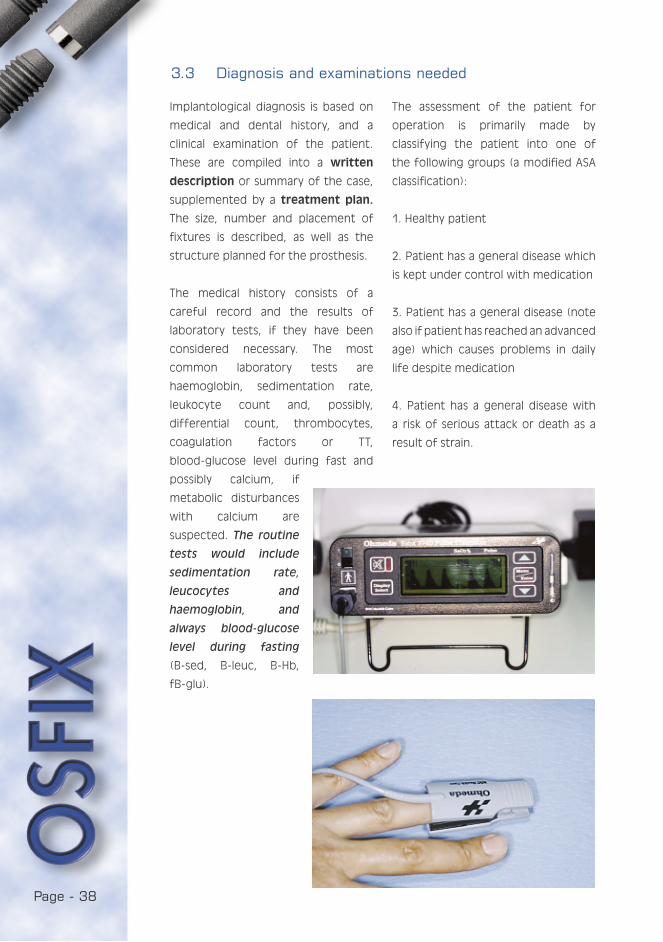
YOU ARE IN:The first group always qualifies for
operation. For groups 2 and 3 it
is recommended that some form
of sedation be used during the
procedures, and for groups 3 and
4 there also has to be a vascular
connection, the ability to monitor
vital functions (preoperative EKG and
preoperative pulse oximeter) and a
professional emergency specialist,
such as an anaesthetist, present during
the procedures. The treatment of
group 4 patients should be avoided
with implantological implications, or
if treatment is chosen, it should take
place in a unit corresponding to
hospital conditions.
Dental history includes earlier
procedures: fillings, periodontics,
extractions, surgery or possible
occlusal therapy.
Clinical examination concentrates on
obtaining a full oral status. Plaster
model analysis of the relation of jaws,
anterior and lateral photograph of
the patient’s face as well as intraoral
photograph might also be useful.
PART I: Clinical
1. INTRODUCTION
2. OSTEOINTEGRATION AND TITANIUM IMPLANTS
3. PLANNING THE TREATMENT
3.1 Indications
3.2 Contraindications
3.3 Diagnosis and examinations needed
3.4 Placing the implants
4. THE PROCEDURES
5. EXAMPLES
6. FAILURES
PART II: Laboratory
PART III: Hygiene
PART IV: Sedation
PART V: Studies
Page - 40
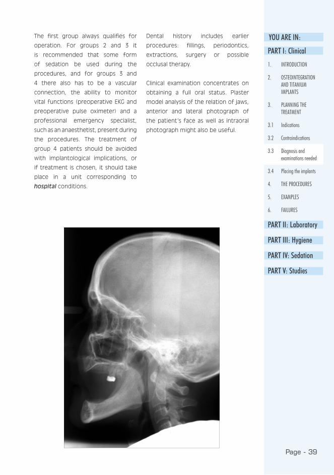
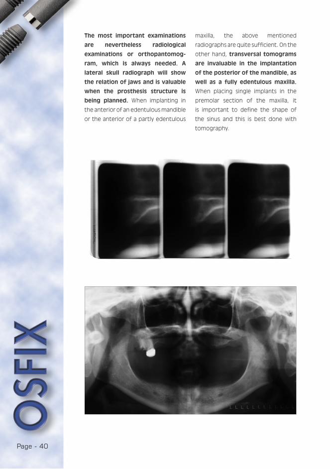
The most important examinations
are nevertheless radiological
examinations or orthopantomog-
ram, which is always needed. A
lateral skull radiograph will show
the relation of jaws and is valuable
when the prosthesis structure is
being planned. When implanting in
the anterior of an edentulous mandible
or the anterior of a partly edentulous
maxilla, the above mentioned
radiographs are quite sufficient. On the
other hand, transversal tomograms
are invaluable in the implantation
of the posterior of the mandible, as
well as a fully edentulous maxilla.
When placing single implants in the
premolar section of the maxilla, it
is important to define the shape of
the sinus and this is best done with
tomography.
Page - 41
YOU ARE IN:3.4 Placing the implants
3.4.1 Maxilla
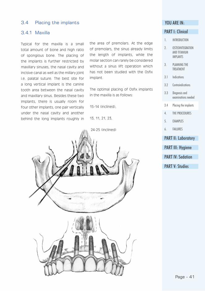
Typical for the maxilla is a small
total amount of bone and high ratio
of spongious bone. The placing of
the implants is further restricted by
maxillary sinuses, the nasal cavity and
incisive canal as well as the millary joint
i.e. palatal suture. The best site for
a long vertical implant is the canine
tooth area between the nasal cavity
and maxillary sinus. Besides these two
implants, there is usually room for
four other implants, one pair vertically
under the nasal cavity and another
behind the long implants roughly in
the area of premolars. At the edge
of premolars, the sinus already limits
the length of implants, while the
molar section can rarely be considered
without a sinus lift operation which
has not been studied with the Osfix
implant.
The optimal placing of Osfix implants
in the maxilla is as follows:
15-14 (inclined),
13, 11, 21, 23,
24-25 (inclined)
PART I: Clinical
1. INTRODUCTION
2. OSTEOINTEGRATION AND TITANIUM IMPLANTS
3. PLANNING THE TREATMENT
3.1 Indications
3.2 Contraindications
3.3 Diagnosis and examinations needed
3.4 Placing the implants
4. THE PROCEDURES
5. EXAMPLES
6. FAILURES
PART II: Laboratory
PART III: Hygiene
PART IV: Sedation
PART V: Studies
Page - 42
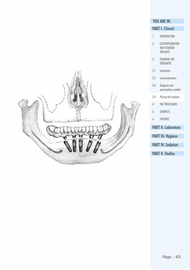
The best area for implants in the
mandible is the anterior area between
the mental foramina, if this area
contains ca. 10 mm of bone, it
is sufficient for implantation. When
placing the implants in the mandible,
it should be remembered that the
mandibular canal makes an anterior
loop just before reaching the surface,
and therefore the implant cannot be
placed directly adjacent to the mental
foramens. The molar area of the
mandible may be used for implantation
if there is ca. 11 mm of bone above
the mandibular canal.
The sharp crestal area of the mandible
makes the planning of implant
treatment more complicated, as it
has to be excised when installing
the implant. It also has to be noted
that the orthopantomograph is greatly
enlarged (horizontally 50-70 %,
vertically 10-30 %). The best result
3.4.2 Mandible
can be obtained when there is room
between the mental foramina for:
Six 11 mm long Osfix implants,
Five or six 13.5 mm long Osfix implants,
or
Four or five 16 mm long implants
(BiOsfix).
The basic solution in the mandible for
Osfix implantation is, almost without
exception, five 13.5 mm long implants,
of which the outermost pair is placed
at the foramen mentale with the apical
head inclined towards the median line;
the middle implants in the median line
of the mandible and one pair between
the two others (thus forming a fan
shape):
44 (inclined),
43-42, 41-31, 32-33,
34 (inclined)
Page - 43
YOU ARE IN:
PART I: Clinical
1. INTRODUCTION
2. OSTEOINTEGRATION AND TITANIUM IMPLANTS
3. PLANNING THE TREATMENT
3.1 Indications
3.2 Contraindications
3.3 Diagnosis and examinations needed
3.4 Placing the implants
4. THE PROCEDURES
5. EXAMPLES
6. FAILURES
PART II: Laboratory
PART III: Hygiene
PART IV: Sedation
PART V: Studies
Page - 44
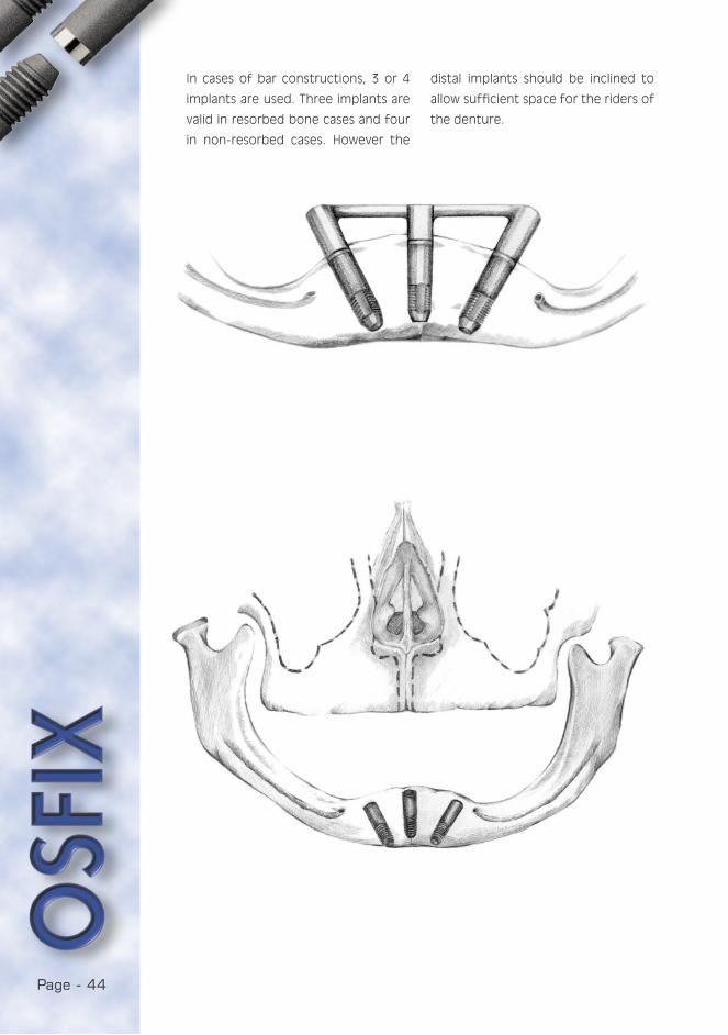
In cases of bar constructions, 3 or 4
implants are used. Three implants are
valid in resorbed bone cases and four
in non-resorbed cases. However the
distal implants should be inclined to
allow sufficient space for the riders of
the denture.

Page - 45
YOU ARE IN:
PART I: Clinical
1. INTRODUCTION
2. OSTEOINTEGRATION AND TITANIUM IMPLANTS
3. PLANNING THE TREATMENT
3.1 Indications
3.2 Contraindications
3.3 Diagnosis and examinations needed
3.4 Placing the implants
4. THE PROCEDURES
5. EXAMPLES
6. FAILURES
PART II: Laboratory
PART III: Hygiene
PART IV: Sedation
PART V: Studies

Page - 46
The placing of the implants should
allow enough bone to be left between
the implants. A rule of thumb would be
to leave a minimum of one implant’s
width of bone: when 3.75 mm implants
are used, ca. 4 mm bone should be
left between the implants. It should
3.4.3 The mutual placing of implants
also be noted that Osfix implants are
always placed in a fan shape, avoiding
parallel implantation. The fan may be
divergent or convergent, but the space
needed by impression posts should be
borne in mind.
Page - 47
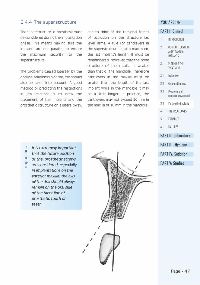
YOU ARE IN:3.4.4 The superstructure
The superstructure i.e. prosthesis must
be considered during the implantation
phase. This means making sure the
implants are not parallel, to ensure
the maximum security for the
superstructure.
The problems caused laterally by the
occlusal relationship of the jaws should
also be taken into account. A good
method of predicting the restrictions
in jaw relations is to draw the
placement of the implants and the
prosthetic structure on a lateral x-ray,
and to think of the torsional forces
of occlusion on the structure i.e.
lever arms. A rule for cantilevers in
the superstructure is, at a maximum,
the last implant’s length. It must be
remembered, however, that the bone
structure of the maxilla is weaker
than that of the mandible. Therefore
cantilevers in the maxilla must be
smaller than the length of the last
implant while in the mandible it may
be a little longer. In practice, the
cantilevers may not exceed 20 mm in
the maxilla or 10 mm in the mandible.
It is extremely important
that the future position
of the prosthetic screws
are considered, especially
in implantations on the
anterior maxilla: the axis
of the drill should always
remain on the oral side
of the facet line of
prosthetic tooth or
teeth.
impo
rtan
tPART I: Clinical
1. INTRODUCTION
2. OSTEOINTEGRATION AND TITANIUM IMPLANTS
3. PLANNING THE TREATMENT
3.1 Indications
3.2 Contraindications
3.3 Diagnosis and examinations needed
3.4 Placing the implants
4. THE PROCEDURES
5. EXAMPLES
6. FAILURES
PART II: Laboratory
PART III: Hygiene
PART IV: Sedation
PART V: Studies

Page - 48
3.4.5 Partial prostheses or short bridges
The fixation of a partial prosthesis to
the bone is, almost without exception,
based on three Osfix implants in an
edentulous area. There is always room
for these when the width of the
edentulous area exceeds 20-25 mm.
If the opening is narrower than 20
mm, two BiOsfix implants are used.
In practice, four or more implants
should be used in wide toothless areas
where implants are faced with torsion
forces, such as in the frontal area.
In the molar area, implants also face
rotational forces that tend to open
occlusal screws, especially where a joint
between the bridge and the implants
does not fully prevent sideways
movement.
3.4.6 Grading of bone for design construction
The outer compact layer of bone may
be thin or thick, whilst spongious
bone may be loose or dense. This
grading alone offers four variations.
The resorption in the bone may be
slight, medium or strong. When this
factor is taken into account, we
face 12 different variations, each
posing an individual implantation
problem. Therefore, the quality of
the bone should always be graded
before implantation. The best bone
for implantation is slightly resorbed,
with a dense spongy bone. A poor
one is a strongly resorbed bone with a
thin compact layer and a loose spongy
bone.
Totally fixed prostheses cannot be
fabricated in a strongly resorbed
mandible, but overdentures supported
by two, or preferably four, implants
should be used. In such cases, the
fastening of the overdenture to the
implant uses the mesiostructure i.e.
the Osfix bar. Dalbo-type fasteners
should not be used, as they would
place considerably greater occlusional
and torsional forces on the implants
compared to bar structures. It is
extremely rare to find a patient with
insufficient bone in the mandible for
an overdenture solution. In the maxilla,
an implant supported overdenture is
not a good solution, as the thickness of
the structures often severely disrupts
speaking.
Page - 49
YOU ARE IN:
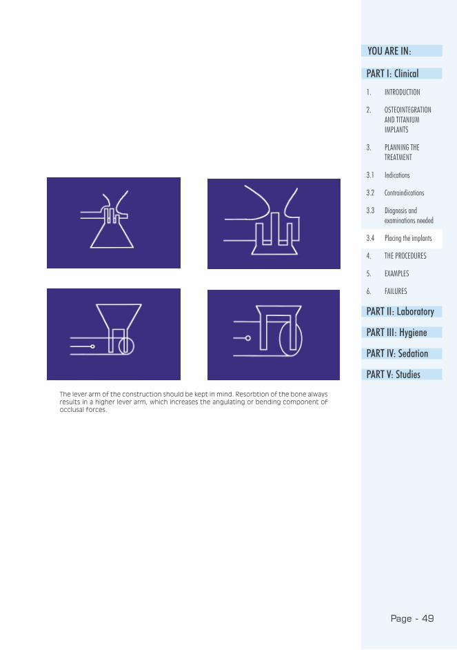
The lever arm of the construction should be kept in mind. Resorbtion of the bone always results in a higher lever arm, which increases the angulating or bending component of occlusal forces.
PART I: Clinical
1. INTRODUCTION
2. OSTEOINTEGRATION AND TITANIUM IMPLANTS
3. PLANNING THE TREATMENT
3.1 Indications
3.2 Contraindications
3.3 Diagnosis and examinations needed
3.4 Placing the implants
4. THE PROCEDURES
5. EXAMPLES
6. FAILURES
PART II: Laboratory
PART III: Hygiene
PART IV: Sedation
PART V: Studies

Page - 50
• Examinations
• Planning
• Placing the implants
• Relining for the prosthesis (e.g. with a temporary soft material when needed)
• Secondary operation after 3-6 months
• Placing of the healing posts.
• Impression
• Fitting of the framework
• Placing of the prosthesis and postoperative radiograph
• Control call and training in oral hygiene
• Annual recall, service and radiological follow-up of the prosthesis
4. THE PROCEDURES
Appointments required for a prosthesis fixed to the jawbone
4.1 Surgery - primary operations
4.1.1 Aseptic and other preparations
Personnel: Before the start of the
implantation operation, all instruments
must be sterilised. The elimination
of the patient’s own flora must be
ensured. The easiest way to do this
is to make the patient wash his own
face with a Hibiscrub® (chlorhexidin)
skin wash, and rinse his mouth with a
Corsodyl® (also chlorhexidin) solution.
After this, and before any other
preparations, the patient’s blood
pressure is measured. Blood pressure
should also be measured after the
procedure, and results recorded (also
note the points mentioned on the
patient’s eligibility for operation).
Before draping, the nurse will carefully
cleanse the skin with alcohol. The
drapes should be large enough to
ensure that no contamination is
transferred accidentally from the
surfaces of the operating theatre to
the sterile area. The outfit of the
surgeon and the primary assistant
includes bonnet, masks, sterile gloves
and surgical gown. The implantation
procedure practically always requires
another nurse or an non-sterile or
circulating assistant to open the
implant cases and pass the sterile
contents to the surgeon.
Room: When considering the
suitability of an ordinary consulting
room for implant surgery, the following
points should be considered:
1. The microbiological purity of the
air conditioning and ventilation
system
2. How well the floor can be cleaned
3. Sufficient light that can be
correctly directed under sterile
conditions
4. Whether the suction system gets
blocked when accumulated blood
begins to coagulate in the tubes
5. The drill and engine should
be powerful enough, and the
handpiece able to be sterilised
Page - 51
YOU ARE IN:
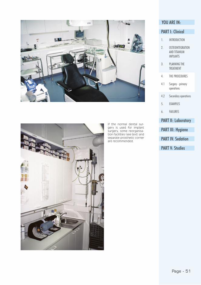
If the normal dental sur-gery is used for implant surgery, some reorganisa-tion facilities (see text) and separate prosthetic corner are recommended.
PART I: Clinical
1. INTRODUCTION
2. OSTEOINTEGRATION AND TITANIUM IMPLANTS
3. PLANNING THE TREATMENT
4. THE PROCEDURES
4.1 Surgery - primary operations
4.2 Secondary operations
5. EXAMPLES
6. FAILURES
PART II: Laboratory
PART III: Hygiene
PART IV: Sedation
PART V: Studies

Page - 52
6. The room should have enough
space for possible reorganisation
7. Mobile equipment units facilitate
organisation
8. It must be possible to monitor the
vital functions of a fully covered
patient with automatic equipment
e.g. with a pulse oximeter
Instruments: The cleaning
programme for the correct surgical
instruments includes three steps:
1. Soaking in a phenolic detergent
solution that dissolves the proteins
contaminating the instruments
(e.g. in a dish-washing machine)
2. Rinsing with alcohol to dissolve the
final remaining fats (e.g. slightly
denatured alcohol is sprayed on
the instrument basket)
3. Autoclave sterilisation
After cleaning, all instruments are
sterilised either in the autoclave or
in the hot air cabinet. It must be
remembered, however, that the hot
air cabinet usually blunts the edges
of the cutting instruments. Therefore
the autoclave is always used for
these. Small instruments such as extra
drills should be wrapped in double
sterilisation packages to ensure easier
handling in case they are needed
during the procedure. Bowls should
be placed in the autoclave on edge
to prevent cold air remaining at the
bottom of the bowl.
On the day of the operation, the
operating room must be carefully
cleaned and washed with a
disinfectant. Sufficient drape material
should always be secured. It can be
obtained ready sterilised or as non-
sterile “sheets“ that can be sterilised
in the autoclave.
OUTFIT AND STERILE ACCESSORIES
Surgeon + primary assistant
• clean clothes
• surgical handwash with Hibiscrub®
• mask and bonnet
• sterile gown and gloves
Patient
• facial wash with Hibiscrub® + mouth rinse Corsodyl®
• cleansing with alcohol from nose to chin
• face drape and skin tape
Non-sterile assistant
• clean clothes
• mask and bonnet
Surgical equipment
• scalpel, periosteal elevator, hooks, scissors, needle holder, clamps
• rinsing syringes, needle, solution and bowl
• a strong engine capable of 30,000 rpm
• sterile water pump
Page - 53
YOU ARE IN:• fast (1:1 or 1:2) straight handpiece with fastening for external cooling water
• a speed reduced hand piece (e.g. Micro-Mega® 20 IMK, 1,500 rpm with a contra-angle head with internal cooling)
• suction tube with a plastic edge
• gauze folds, suture material
• Osfix drill kit or sufficient cannon drills
• implants
• tapping instruments
• turning tools (ratchet and torque tap)
• antibiotic eye ointment (Terracortril®)
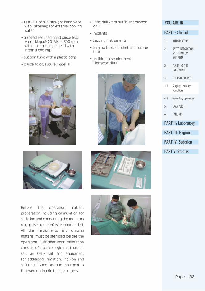
Before the operation, patient
preparation including cannulation for
sedation and connecting the monitors
(e.g. pulse oximeter) is recommended.
All the instruments and draping
material must be sterilised before the
operation. Sufficient instrumentation
consists of a basic surgical instrument
set, an Osfix set and equipment
for additional irrigation, incision and
suturing. Good aseptic protocol is
followed during first stage surgery.
PART I: Clinical
1. INTRODUCTION
2. OSTEOINTEGRATION AND TITANIUM IMPLANTS
3. PLANNING THE TREATMENT
4. THE PROCEDURES
4.1 Surgery - primary operations
4.2 Secondary operations
5. EXAMPLES
6. FAILURES
PART II: Laboratory
PART III: Hygiene
PART IV: Sedation
PART V: Studies
Page - 54
Local anaesthesia: Xylocain
Adrenalin® (lidocain with epinephrine)
provides an adequate haemostasis.
Thus local anaesthesia is also infiltrated
to reach haemostasis. Mandibular block
injection can be avoided with
implantation on the mandibular canal
to prevent unnecessary nerve injuries.
To reach sufficient anaesthesia in
these cases, the use of both Xylocain
Adrenalin® and Citanest Octapressin®
(prilocaine with felypressin) are
recommended, and they should also
be injected under the periosteum!
Sedation: Dormicum® (midazolam)
15 mg one hour before procedure
(7.5 mg for elderly people) per os or
slow titration (2-10 mg) intravenously
directly prior to procedure, when
needed (see PART IV).
Antibiotics: Kefexin® 500 mg
(cefalosporin) per os, 1x3, 10 days
postoperatively.
Analgesic: Felden® 20 mg (piroxicam)
per os, 2x1 2 days, 1x1 5 days and
an addition of Indalgin® (indometacin
and ethylic morphine) per os 1x3,
when needed.
4.1.2 Medication
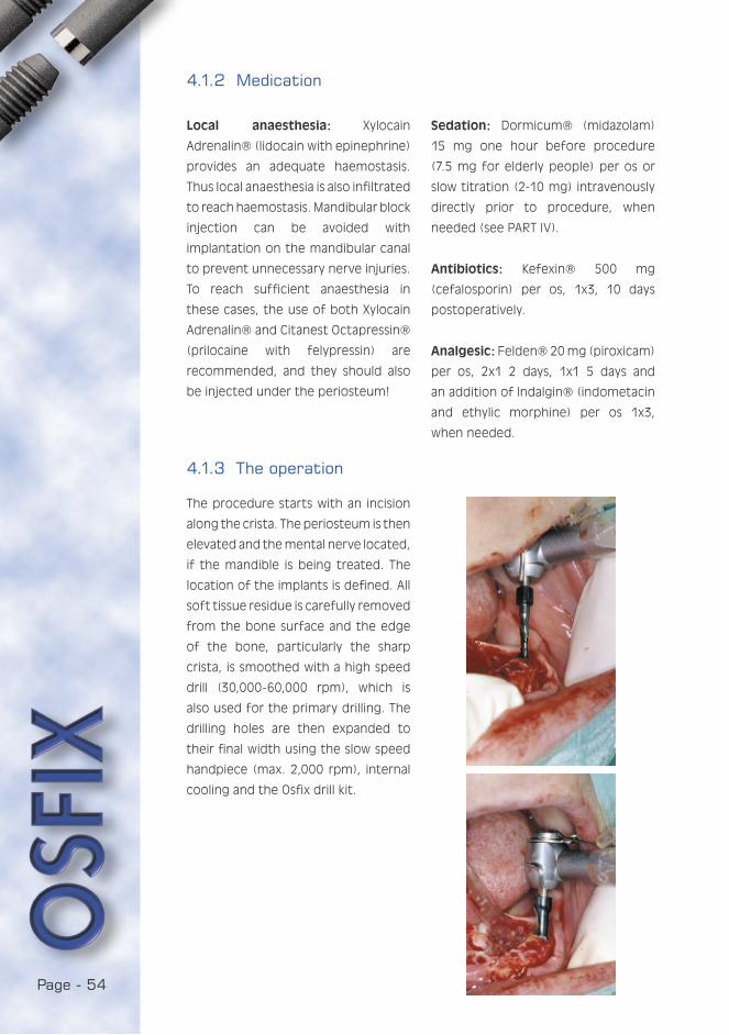
4.1.3 The operation
The procedure starts with an incision
along the crista. The periosteum is then
elevated and the mental nerve located,
if the mandible is being treated. The
location of the implants is defined. All
soft tissue residue is carefully removed
from the bone surface and the edge
of the bone, particularly the sharp
crista, is smoothed with a high speed
drill (30,000-60,000 rpm), which is
also used for the primary drilling. The
drilling holes are then expanded to
their final width using the slow speed
handpiece (max. 2,000 rpm), internal
cooling and the Osfix drill kit.

Page - 55
YOU ARE IN:When all implant sites have been
finished, the implants are placed and
tapped into place. PART I: Clinical
1. INTRODUCTION
2. OSTEOINTEGRATION AND TITANIUM IMPLANTS
3. PLANNING THE TREATMENT
4. THE PROCEDURES
4.1 Surgery - primary operations
4.2 Secondary operations
5. EXAMPLES
6. FAILURES
PART II: Laboratory
PART III: Hygiene
PART IV: Sedation
PART V: Studies

Page - 56
Page - 57
YOU ARE IN:
PART I: Clinical
1. INTRODUCTION
2. OSTEOINTEGRATION AND TITANIUM IMPLANTS
3. PLANNING THE TREATMENT
4. THE PROCEDURES
4.1 Surgery - primary operations
4.2 Secondary operations
5. EXAMPLES
6. FAILURES
PART II: Laboratory
PART III: Hygiene
PART IV: Sedation
PART V: Studies
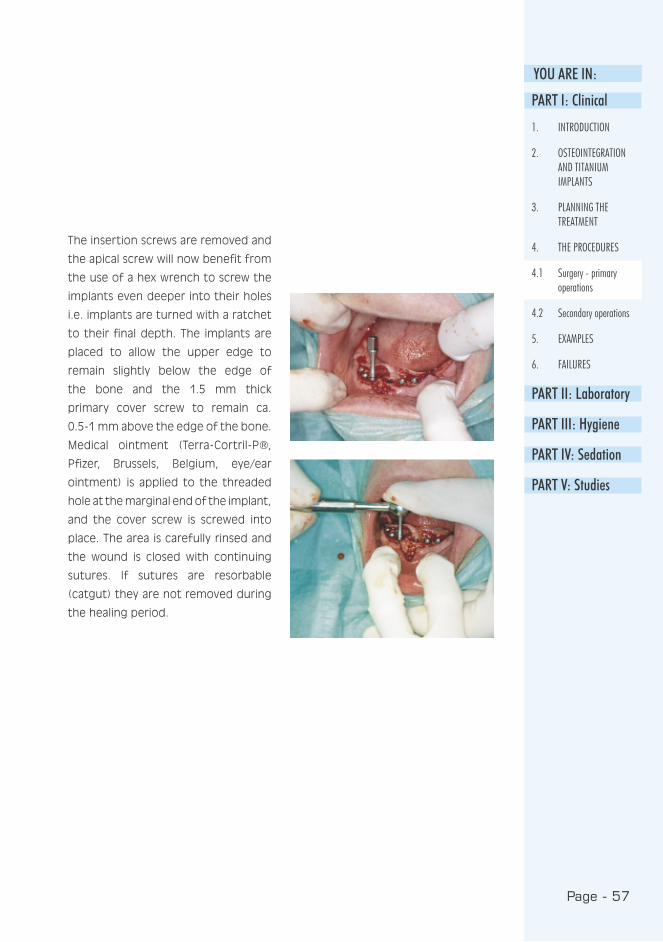
The insertion screws are removed and
the apical screw will now benefit from
the use of a hex wrench to screw the
implants even deeper into their holes
i.e. implants are turned with a ratchet
to their final depth. The implants are
placed to allow the upper edge to
remain slightly below the edge of
the bone and the 1.5 mm thick
primary cover screw to remain ca.
0.5-1 mm above the edge of the bone.
Medical ointment (Terra-Cortril-P®,
Pfizer, Brussels, Belgium, eye/ear
ointment) is applied to the threaded
hole at the marginal end of the implant,
and the cover screw is screwed into
place. The area is carefully rinsed and
the wound is closed with continuing
sutures. If sutures are resorbable
(catgut) they are not removed during
the healing period.

Page - 58
Two types of cover screws are available i. e.
flat (1.0 mm) and normal (1.5 mm)
Page - 59
YOU ARE IN:
After the procedure, the patient should
be given time to rest at the surgery
before leaving, and he should leave
with an escort whenever sedation
has been used. The patient is given
a prescription for antibiotics and
analgesics. The prosthesis is thinned
sufficiently so as not to strain the
possibly protruding implants. The
prosthesis is fitted in place and a
good fit is secured. Later, a soft
relining material (Viscogel® or Ufigel®)
is spread on the prosthesis’ base
and placed in the patient’s mouth.
A suitable timing for the second, i.e.
impression, operation is 3-6 months
from the initial operation.
The exposure of the cover screw during
the healing period is quite common
and causes very few real problems.
Instructions for cleaning are essential;
other actions are mostly harmful.
4.1.4 Postoperative treatment of the patient
4.2 Secondary operations
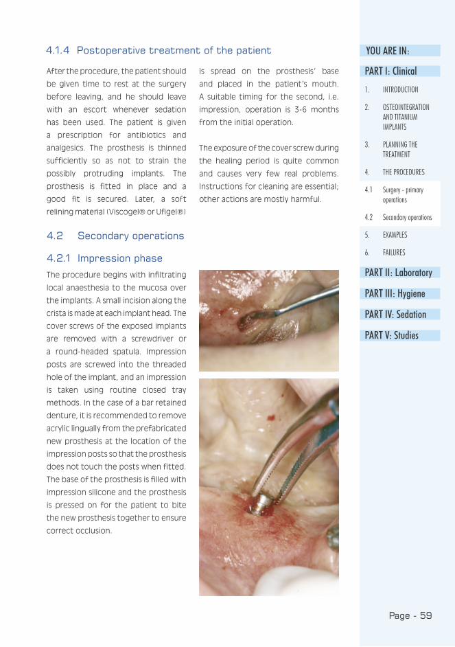
4.2.1 Impression phase
The procedure begins with infiltrating
local anaesthesia to the mucosa over
the implants. A small incision along the
crista is made at each implant head. The
cover screws of the exposed implants
are removed with a screwdriver or
a round-headed spatula. Impression
posts are screwed into the threaded
hole of the implant, and an impression
is taken using routine closed tray
methods. In the case of a bar retained
denture, it is recommended to remove
acrylic lingually from the prefabricated
new prosthesis at the location of the
impression posts so that the prosthesis
does not touch the posts when fitted.
The base of the prosthesis is filled with
impression silicone and the prosthesis
is pressed on for the patient to bite
the new prosthesis together to ensure
correct occlusion.
PART I: Clinical
1. INTRODUCTION
2. OSTEOINTEGRATION AND TITANIUM IMPLANTS
3. PLANNING THE TREATMENT
4. THE PROCEDURES
4.1 Surgery - primary operations
4.2 Secondary operations
5. EXAMPLES
6. FAILURES
PART II: Laboratory
PART III: Hygiene
PART IV: Sedation
PART V: Studies

Page - 60
Once the impression material has
hardened, the tray/prosthesis is
removed. The quality of the impression
is tested by placing an impression
post in each hole and testing for
movement by hand. The impression is
sent to the dental laboratory where the
impression is equipped with laboratory
pieces and cast in plaster. The cover
screws are returned to the implants
or replaced by a healing set, and the
wound is closed normally.
If at this phase it is found that the
implant is not secure, or that bone has
been lost up to one third of the length
Different impression
posts are available
of the implant, the implant must be
removed in this procedure.
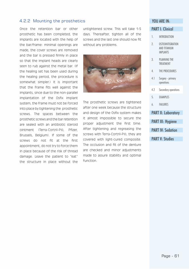
Page - 61
YOU ARE IN:
Once the retention bar or other
prosthetic has been completed, the
implants are located with the help of
the bar/frame: minimal openings are
made, the cover screws are removed
and the bar is pressed firmly in place
so that the implant heads are clearly
seen to rub against the metal bar. (If
the healing set has been used during
the healing period, the procedure is
somewhat simpler.) It is important
that the frame fits well against the
implants, since due to the non-parallel
implantation of the Osfix implant
system, the frame must not be forced
into place by tightening the prosthetic
screws. The spaces between the
prosthetic screws and the bar retention
are sealed with an antibiotic steroid
ointment (Terra-Cortril-P©, Pfizer,
Brussels, Belgium). If some of the
screws do not fit at the first
appointment, do not try to force them
in place because of the risk of thread
damage. Leave the patient to “eat“
the structure in place without the
untightened screw. This will take 1-5
days. Thereafter, tighten all of the
screws and the last one should now fit
without any problems.
The prosthetic screws are tightened
after one week because the structure
and design of the Osfix system makes
it almost impossible to secure the
proper adjustment the first time.
After tightening and regreasing the
screws with Terra-Cortril-P©, they are
covered with light-cured composite.
The occlusion and fit of the denture
are checked and minor adjustments
made to assure stability and optimal
function.
4.2.2 Mounting the prosthetics
PART I: Clinical
1. INTRODUCTION
2. OSTEOINTEGRATION AND TITANIUM IMPLANTS
3. PLANNING THE TREATMENT
4. THE PROCEDURES
4.1 Surgery - primary operations
4.2 Secondary operations
5. EXAMPLES
6. FAILURES
PART II: Laboratory
PART III: Hygiene
PART IV: Sedation
PART V: Studies
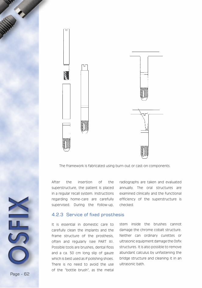
Page - 62
The framework is fabricated using burn-out or cast-on components.
After the insertion of the
superstructure, the patient is placed
in a regular recall system. Instructions
regarding home-care are carefully
supervised. During the follow-up,
radiographs are taken and evaluated
annually. The oral structures are
examined clinically and the functional
efficiency of the superstructure is
checked.
It is essential in domestic care to
carefully clean the implants and the
frame structure of the prosthesis,
often and regularly (see PART III).
Possible tools are brushes, dental floss
and a ca. 50 cm long slip of gauze
which is best used as if polishing shoes.
There is no need to avoid the use
of the “bottle brush“, as the metal
4.2.3 Service of fixed prosthesis
stem inside the brushes cannot
damage the chrome cobalt structure.
Neither can ordinary curettes or
ultrasonic equipment damage the Osfix
structures. It is also possible to remove
abundant calculus by unfastening the
bridge structure and cleaning it in an
ultrasonic bath.
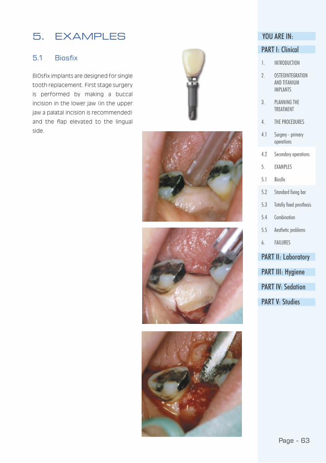
Page - 63
YOU ARE IN:
5.1 Biosfix
BiOsfix implants are designed for single
tooth replacement. First stage surgery
is performed by making a buccal
incision in the lower jaw (in the upper
jaw a palatal incision is recommended)
and the flap elevated to the lingual
side.
5. EXAMPLESPART I: Clinical
1. INTRODUCTION
2. OSTEOINTEGRATION AND TITANIUM IMPLANTS
3. PLANNING THE TREATMENT
4. THE PROCEDURES
4.1 Surgery - primary operations
4.2 Secondary operations
5. EXAMPLES
5.1 Biosfix
5.2 Standard fixing bar
5.3 Totally fixed prosthesis
5.4 Combination
5.5 Aesthetic problems
6. FAILURES
PART II: Laboratory
PART III: Hygiene
PART IV: Sedation
PART V: Studies

Page - 64
A pilot drill is used to enlarge the hole
to approx. 3.5 mm. The final drill is
then placed and intruded until the
counter-sunk portion is partly inside
the bone. The implant is removed
from its container using haemostats
(mosquitoes) and placed into the
socket with the same instrument. The
implant is pushed inside with a finger
or it may be carefully tapped in using
a mallet and tapping pin.

Page - 65
YOU ARE IN:
PART I: Clinical
1. INTRODUCTION
2. OSTEOINTEGRATION AND TITANIUM IMPLANTS
3. PLANNING THE TREATMENT
4. THE PROCEDURES
5. EXAMPLES
5.1 Biosfix
5.2 Standard fixing bar
5.3 Totally fixed prosthesis
5.4 Combination
5.5 Aesthetic problems
6. FAILURES
PART II: Laboratory
PART III: Hygiene
PART IV: Sedation
PART V: Studies
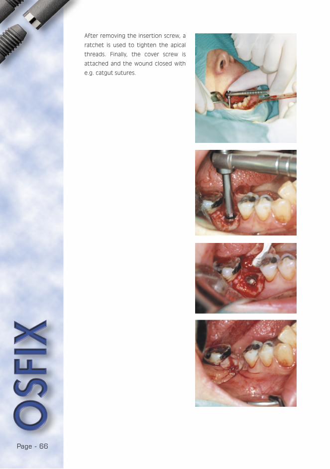
Page - 66
After removing the insertion screw, a
ratchet is used to tighten the apical
threads. Finally, the cover screw is
attached and the wound closed with
e.g. catgut sutures.

Page - 67
YOU ARE IN:
PART I: Clinical
1. INTRODUCTION
2. OSTEOINTEGRATION AND TITANIUM IMPLANTS
3. PLANNING THE TREATMENT
4. THE PROCEDURES
5. EXAMPLES
5.1 Biosfix
5.2 Standard fixing bar
5.3 Totally fixed prosthesis
5.4 Combination
5.5 Aesthetic problems
6. FAILURES
PART II: Laboratory
PART III: Hygiene
PART IV: Sedation
PART V: Studies
After second stage surgery and
impression taking, the crown, which
has integrated rotation control
(prosthetic cast-on component) and a
prosthetic screw, is delivered from the
dental laboratory. The healing post is
removed and ...
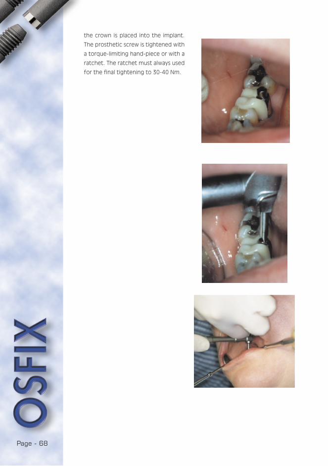
Page - 68
the crown is placed into the implant.
The prosthetic screw is tightened with
a torque-limiting hand-piece or with a
ratchet. The ratchet must always used
for the final tightening to 30-40 Nm.

Page - 69
YOU ARE IN:5.2 Standard fixing bar
The first and second stage surgical
procedures for Osfix implants are
described in chap. 4.1.3. Only
impression taking and prosthetic
procedures are described in
following:
After primary surgery, a healing period
of three months is required before
the commencement of second stage
surgery. During this time, new dentures
for both the upper and lower jaw
are fabricated: Impressions are
superimposed with a face-bow and
the dentures are arranged following
the rule that the canines are located
in a line which is parallel with the
line between the condyles of the
jawbone.
Impression posts are screwed into the
implant, it is also necessary to remove
acrylic lingually from the prefabricated
new prosthesis at the location of the
impression posts. This is to prevent the
prosthesis from touching the posts
when fitted.
PART I: Clinical
1. INTRODUCTION
2. OSTEOINTEGRATION AND TITANIUM IMPLANTS
3. PLANNING THE TREATMENT
4. THE PROCEDURES
5. EXAMPLES
5.1 Biosfix
5.2 Standard fixing bar
5.3 Totally fixed prosthesis
5.4 Combination
5.5 Aesthetic problems
6. FAILURES
PART II: Laboratory
PART III: Hygiene
PART IV: Sedation
PART V: Studies
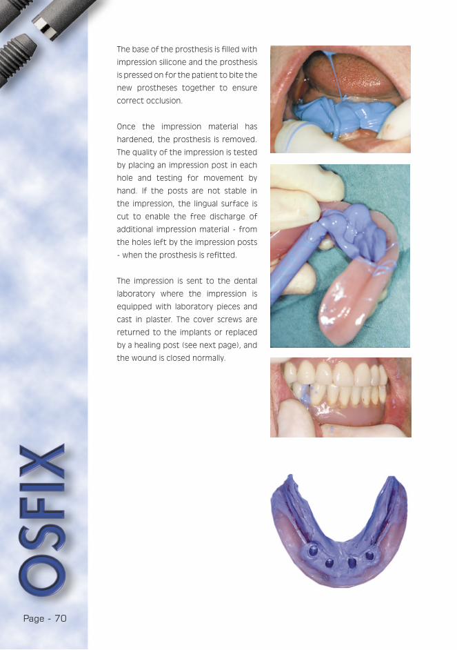
Page - 70
The base of the prosthesis is filled with
impression silicone and the prosthesis
is pressed on for the patient to bite the
new prostheses together to ensure
correct occlusion.
Once the impression material has
hardened, the prosthesis is removed.
The quality of the impression is tested
by placing an impression post in each
hole and testing for movement by
hand. If the posts are not stable in
the impression, the lingual surface is
cut to enable the free discharge of
additional impression material - from
the holes left by the impression posts
- when the prosthesis is refitted.
The impression is sent to the dental
laboratory where the impression is
equipped with laboratory pieces and
cast in plaster. The cover screws are
returned to the implants or replaced
by a healing post (see next page), and
the wound is closed normally.

Page - 71
YOU ARE IN:PART I: Clinical
1. INTRODUCTION
2. OSTEOINTEGRATION AND TITANIUM IMPLANTS
3. PLANNING THE TREATMENT
4. THE PROCEDURES
5. EXAMPLES
5.1 Biosfix
5.2 Standard fixing bar
5.3 Totally fixed prosthesis
5.4 Combination
5.5 Aesthetic problems
6. FAILURES
PART II: Laboratory
PART III: Hygiene
PART IV: Sedation
PART V: Studies
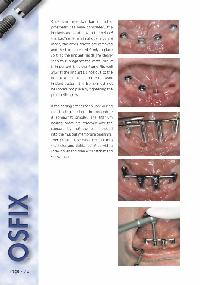
Page - 72
Once the retention bar or other
prosthetic has been completed, the
implants are located with the help of
the bar/frame: minimal openings are
made, the cover screws are removed
and the bar is pressed firmly in place
so that the implant heads are clearly
seen to rub against the metal bar. It
is important that the frame fits well
against the implants, since due to the
non-parallel implantation of the Osfix
implant system, the frame must not
be forced into place by tightening the
prosthetic screws.
If the healing set has been used during
the healing period, the procedure
is somewhat simpler: The titanium
healing posts are removed and the
support legs of the bar intruded
into the mucous membrane openings.
Then prosthetic screws are placed into
the holes and tightened, first with a
screwdriver and then with ratchet and
screwdriver.
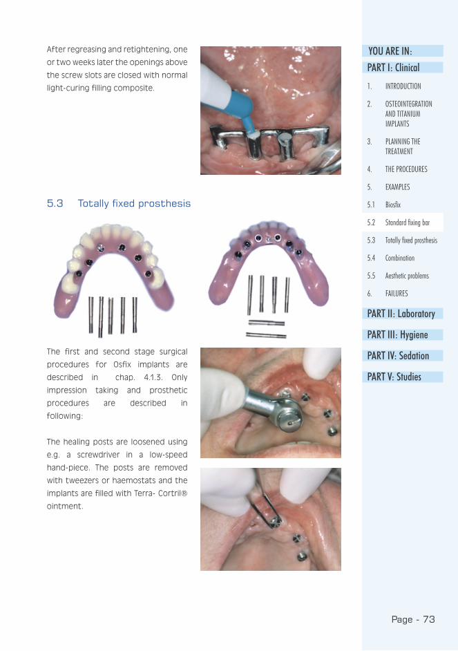
Page - 73
YOU ARE IN:PART I: Clinical
1. INTRODUCTION
2. OSTEOINTEGRATION AND TITANIUM IMPLANTS
3. PLANNING THE TREATMENT
4. THE PROCEDURES
5. EXAMPLES
5.1 Biosfix
5.2 Standard fixing bar
5.3 Totally fixed prosthesis
5.4 Combination
5.5 Aesthetic problems
6. FAILURES
PART II: Laboratory
PART III: Hygiene
PART IV: Sedation
PART V: Studies
5.3 Totally fixed prosthesis
The first and second stage surgical
procedures for Osfix implants are
described in chap. 4.1.3. Only
impression taking and prosthetic
procedures are described in
following:
The healing posts are loosened using
e.g. a screwdriver in a low-speed
hand-piece. The posts are removed
with tweezers or haemostats and the
implants are filled with Terra- Cortril®
ointment.
After regreasing and retightening, one
or two weeks later the openings above
the screw slots are closed with normal
light-curing filling composite.

Page - 74
Impression posts are screwed into
place. Impression taking by both the
normal closed tray method and regular
silicon techniques are performed.
After checking the fit of the framework
with an x-ray and determining the
correct occlusion with wax occlusal
rims (fixed on the framework), the
prosthesis is returned to the dental
laboratory. In the case of the upper
jaw, it is finally fixed, screws secured
and closed as described in the previous
example i.e. bar case.
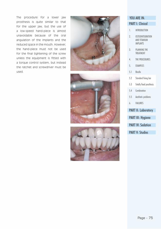
Page - 75
YOU ARE IN:The procedure for a lower jaw
prosthesis is quite similar to that
for the upper jaw, but the use of
a low-speed hand-piece is almost
unavoidable because of the oral
angulation of the implants and the
reduced space in the mouth. However,
the hand-piece must not be used
for the final tightening of the screw
unless the equipment is fitted with
a torque control system, but instead
the ratchet and screwdriver must be
used.
PART I: Clinical
1. INTRODUCTION
2. OSTEOINTEGRATION AND TITANIUM IMPLANTS
3. PLANNING THE TREATMENT
4. THE PROCEDURES
5. EXAMPLES
5.1 Biosfix
5.2 Standard fixing bar
5.3 Totally fixed prosthesis
5.4 Combination
5.5 Aesthetic problems
6. FAILURES
PART II: Laboratory
PART III: Hygiene
PART IV: Sedation
PART V: Studies

Page - 76
In a case where both implants and
natural teeth are present in the
same jaw, a non-fixed combination is
recommended if it is not possible to
leave the teeth intact. Crown pillars
are prepared and impression posts are
placed and impressions taken using
the closed tray method.
5.4 Combination
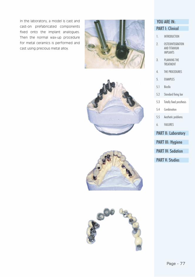
Page - 77
YOU ARE IN:PART I: Clinical
1. INTRODUCTION
2. OSTEOINTEGRATION AND TITANIUM IMPLANTS
3. PLANNING THE TREATMENT
4. THE PROCEDURES
5. EXAMPLES
5.1 Biosfix
5.2 Standard fixing bar
5.3 Totally fixed prosthesis
5.4 Combination
5.5 Aesthetic problems
6. FAILURES
PART II: Laboratory
PART III: Hygiene
PART IV: Sedation
PART V: Studies
In the laboratory, a model is cast and
cast-on prefabricated components
fixed onto the implant analogues.
Then the normal wax-up procedure
for metal ceramics is performed and
cast using precious metal alloy.
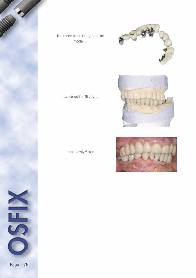
Page - 78
The three piece bridge on the
model…
…cleaned for fitting…
…and newly fitted.

Page - 79
YOU ARE IN:
PART I: Clinical
1. INTRODUCTION
2. OSTEOINTEGRATION AND TITANIUM IMPLANTS
3. PLANNING THE TREATMENT
4. THE PROCEDURES
5. EXAMPLES
5.1 Biosfix
5.2 Standard fixing bar
5.3 Totally fixed prosthesis
5.4 Combination
5.5 Aesthetic problems
6. FAILURES
PART II: Laboratory
PART III: Hygiene
PART IV: Sedation
PART V: Studies
5.5 Aesthetic problems
How to solve aesthetic problems if
the implants are placed protruding
buccally?
-Cut the prosthetic screws and
support-legs (integral abutments) to
the gingival level. If composite for
normal fillings are placed on the
openings, the aesthetics of the gingival
margin is limited. However, this
procedure is acceptable on palatal
openings when lip support is
adequate.
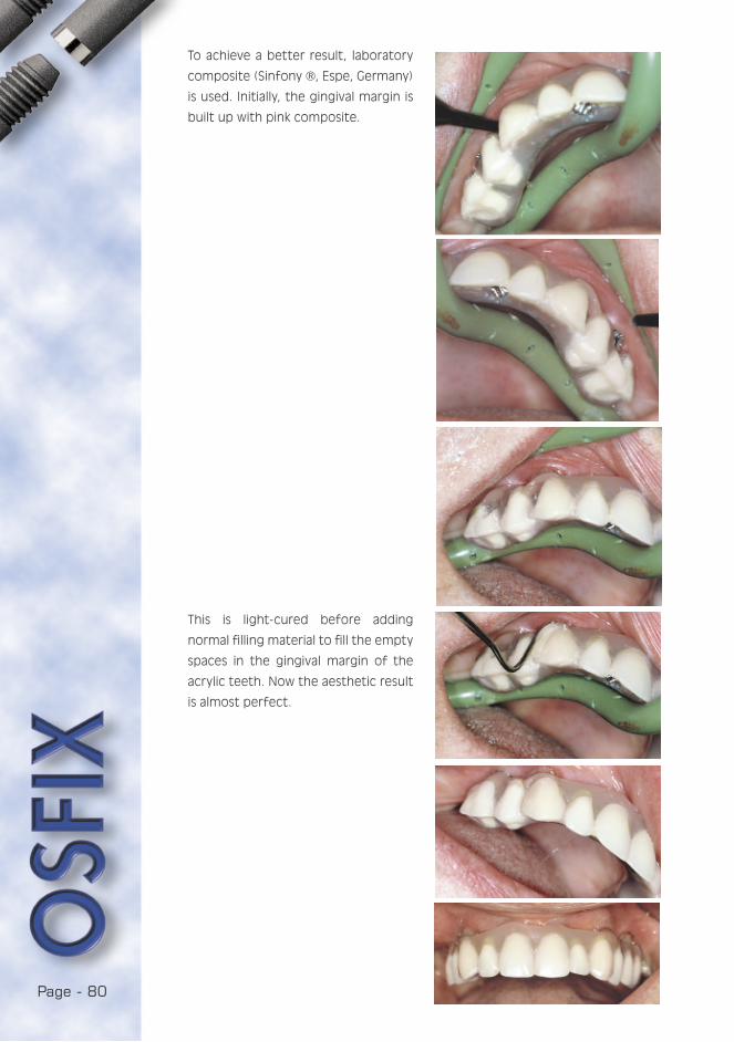
Page - 80
To achieve a better result, laboratory
composite (Sinfony ®, Espe, Germany)
is used. Initially, the gingival margin is
built up with pink composite.
This is light-cured before adding
normal filling material to fill the empty
spaces in the gingival margin of the
acrylic teeth. Now the aesthetic result
is almost perfect.

Page - 81
YOU ARE IN:6. FAILURES
6.1 Loss of Implants
The cause of loss of implants can be
divided into two stages: primary and
secondary losses. Primary loss of the
implant occurs during the secondary
operation or impression taking, or
after short term loading (within the
first year). This is almost always as a
result of surgical failure: Implants used
in cases of dehiscence of the bone,
bone overheated during preparation,
healing has not been trouble-free as
a result of denture irritation, short
implants are overloaded, etc. All of
these are iatrogenic, i.e. doctor
dependent, reasons. Secondary loss is
mainly caused by poor hygiene control,
very few other reasons exist.
6.2 Mistakes in structural design
The commonest mistakes in design are
incorrect positioning of the maxillary
and mandibular anterior implants. The
first prevents the proper aesthetics
of the fixed prosthesis, and do not
leave space enough for the riders in
bar constructions. This type of mistake
happens most often with teams in
which the surgeons are not taking
part in the prosthodontic treatment
at all. It is only a means of avoiding
responsibility to say: “I placed the
implant where the bone was“.
6.3 Mistakes in fabrication
During the impression, casting the
model or framework, mistakes are also
possible: The most frequent failure
during impression taking is that the
impression post moves, i.e. it is not
stable in impression silicone. This
causes an angulation failure between
the implant and the framework
extension. The commonest mistake in
dental laboratories is that the posts
have not been fixed properly, with
glue, into the impression. Thus, whilst
casting the model, one or more posts
is detached by the vibration. This is
visible in the framework as a vertical
error. The final type of laboratory
failure is a horizontal error which is
caused by a poorly controlled casting
procedure. Thus the casting procedure
must be calibrated in every laboratory
as described in the laboratory manual,
part II.
6.4 Patient related factors
If the contraindications for implant
treatment are excluded, the only
patient related factor is the lack of
proper cleaning of the implant work.
This is avoided if the guidelines in part
III are followed.
PART I: Clinical
1. INTRODUCTION
2. OSTEOINTEGRATION AND TITANIUM IMPLANTS
3. PLANNING THE TREATMENT
4. THE PROCEDURES
5. EXAMPLES
5.1 Biosfix
5.2 Standard fixing bar
5.3 Totally fixed prosthesis
5.4 Combination
5.5 Aesthetic problems
6. FAILURES
6.1 Loss of Implants
6.2 Mistakes in structure design
6.3 Mistakes in fabrication
6.4 Patient related factors
PART II: Laboratory
PART III: Hygiene
PART IV: Sedation
PART V: Studies

Page - 82
REFERENCES
Adell R, Lekholm U, Rockler B,
Brånemark P : A 15-year study
of osseointegrated implants in the
treatment of the edentulous jaw. Int J
Oral Surg 1981: 6 : 387-416.
Albrektsson T, Zarb C, Worthington P,
Eriksson A : The long-term efficacy
of currently used dental implants:
A review and proposed criteria of
success. Int J Oral Maxillofac Implants
1986 : 1 : 11-25.
Babbush C, Shimura M : Five-year
statistical and clinical observations
with the IMZ two-stage
osteointegrated implant system. Int
J Oral Maxillofac Implants 1993 : 8 :
245-53.
Barnes C, Fleming L, Mueninghoff L :
SEM evaluation of the in-vitro effects
of an air-abrasive system on various
implant surfaces. Int J Oral Maxillofac
Implants 1991 : 6 : 463-9.
Cox J, Zarb G : The longitudinal clinical
efficacy of osteointegrated implants :
A 3-year report. Int J Oral Maxillofac
Implants 1987 : 2 : 91-100.
Ettinger R, Spivey J, Han D, Koorbusch
G : Measurement of the interface
between bone and immediate
endosseous implants: a pilot study in
dogs. Int J Oral Maxillofac Implants
1993 : 8 : 420-7.
Fugazzotto P, Gulbransen H, Wheeler
S, Lindsay J : The use of IMZ
osteointegrated implants in partially
and completely edentulous patients:
success and failure rates of 2,023
implant cylinders up to 60+ months
in function. Int J Oral Maxillofac
Implants 1993 : 8 : 617-21.
Geis-Gerstorfer J, Weber H, Sauer
K-H : In vitro substance loss due
to galvanic corrosion in Ti implant /
Ni-Cr. supraconstruction systems. Int
J Oral Maxillofac Implants 1989 : 4 :
119-123.
Haider R, Watzek G, Plenk H : Effects
of drill cooling and bone structure on
fixation. Int J Oral Maxillofac Implants
1993 : 8 : 83-91.
Hertel R, Kalk W : Influence of the
dimensions of implant superstructure
on peri-implant bone loss. Int J
Prosthodont 1993 : 6 : 18-24.
Hulterström M, Nilsson U : Cobalt-
chromium as a framework material in
implant-supported fixed prosthesis: a
3-year Follow-up. Int J Oral Maxillofac
Implants 1994 : 4 : 449-454.
Kraut R, Dootson J, McCullen A :
Biomechanical analysis of
osteointegration of IMZ implants in
goat mandibles and maxillae. Int J Oral
Maxillofac Implants 1991 : 6 : 187-94.
Kellett M, Smith G : The epithelial
interface with osteointegrated
implants. Dent-Health (London) 1991 :
30 : 6-9.
Lemons J : Dental implant retrieval
analyses. J Dent Educ 1988 : 52 :
748-756.

Page - 83
YOU ARE IN:Luotio K, Petrelius U : An optional
method for elevation of the mucous
membrane of maxillary sinus and
simultaneous bone augmentation i.e.
sinus lift during dental implant
surgery (in Finnish). Perfis 1994 : 1:
34-6.
Luotio K : IMZ- and Frialit-2 implants
(in Finnish) The Finnish Dentists’
Journal 1997 : 7: 356-362.
Moberg L : Long-term corrosion
studies in vitro of gold. Cobalt-
chromium and nickel-chromium alloys
in contact. Acta Odontol Scand 1985 :
43 : 215-222.
Novaes A, Novaes A : IMZ implants
placed into extraction sockets in
association with membrane therapy
(Gengiflex) and porous
hydroxyapatite: a case report. Int J
Oral Maxillofac Implants 1992 : 7 :
536-40.
Stenberg T : Release of cobalt from
cobalt-chromium alloy construction in
oral cavity of man. Scand J Dent Res
1982 : 90 : 472-479.
Watanabe F, Tawada Y, Komatsu
S, Hata Y : Heat distribution in
bone during preparation of implant
sites: heat analysis by real-time
thermography. Int J Oral Maxillofac
Implants 1992 : 7 : 212-9.
Van-de-Velde E, Thielens P, Schtteet
H, Vanclooster R : Subcutaneous
emphysema of the oral floor during
cleaning of a bridge fixed on an IMZ
implant. Case report. Rev Belg Med
Dent 1991 : 46 : 64-71.

Page - 84

PART I IL ABORATORY
the manual

Page - 86

1. INTRODUCTION
1.1 Osfix manual ....................................................89
1.2 Osfix implant system........................................89
1.3 Osfix dental treatment .....................................89
1.4 The main differences between Osfix
implants and other implant systems..................90
1.5 Laboratory components and instruments...........90
2. CALIBRATION OF CASTING PROCESS IN DENTAL LABORATORIES .....................................91
3. PREPARATION OF MASTER MODEL..........................92
4. BAR RETAINED OVERDENTURE................................92
4.1 Preparation of the denture for impression taking.92
4.2 Waxing-up the bar ............................................93
4.3 Spruing............................................................93
4.4 Finishing ..........................................................94
4.5 Acrylic work .....................................................95
4.6 Keypoints.........................................................95
5. BRIDGE
5.1 Waxing-up the framework ..................................96
5.2 Spruing............................................................96
5.3 Finishing the framework ....................................96
5.4 Building-up the acrylic teeth ..............................96
5.5 Keypoints.........................................................96
6. FIXED FULL ARCH BRIDGE
6.1 Setting-up teeth ..............................................97
6.2 Waxing-up the framework ..................................97
6.3 Spruing............................................................98
6.4 Fitting the framework and finishing.....................98
6.5 Acrylic work .....................................................98
6.6 Keypoints.........................................................99
6.6.1 Occlusal balance............................................99
6.6.2 Gingival margin ..............................................99
7. DISINFECTION OF THE COMPLETED WORK.............100

Page - 88
Page - 89
YOU ARE IN:
This manual is an illustration of the
laboratory procedures of the Osfix
implant system intended for dental
technicians.
The manual describes, step by step, the construction of a
bar retained overdenture, a bridge and a fixed full arch
bridge for which burn-out components are used. If cast-on
components are used, the technical protocol follows general
implant prosthetic principles, and the advices of this part are
only trendsetting.
1. INTRODUCTION1.1 Osfix manual
1.2 Osfix implant system
The Osfix implant is a cylindrical
implant with an apical screw portion
for simple and fast mounting and
improved primary stability. The implant
is made of grade 2 pure titanium and
the implant surface is mechanically
roughened. The length of the implant
is 13.5 mm or 11 mm and the diameter
is 3.75 mm. The Osfix implant is
primarily designed for bar-retained
mandibular overdentures for totally
edentulous patients. It can also be
used for fixed constructions with 5-6
implants or for bridges with at least 3
implants.
1.3 Osfix dental treatment
This two-stage implant system is the
result of several years of development
and research work in university dental
clinics.
In the first surgical stage, the titanium
implants are placed directly into the
bone. The implants osteointegrate for
3-6 months. During this period, the
patient wears their old dentures or a
temporary construction is fabricated.
It is not necessary for the patient
to remain edentulous during the
treatment.
In the second stage, the dentist
takes an impression, on basis of
which the dental laboratory fabricates
the prosthetic restoration. Once the
construction is complete, it is mounted
in place and the occlusion is checked.
Following this, there is a control visit
one or two weeks after the insertion
of the restoration. All operations are
made under local anaesthesia including
premedication when necessary. Post-
operative pain can effectively be
eliminated by the use of medication
prescribed by the dentist.
PART I
PART II
1. INTRODUCTION
1.1 Osfix manual
1.2 Osfix implant system
1.3 Osfix dental treatment
1.4 The main differences between Osfix implants and other implant systems
1.5 Laboratory components and instruments
2. CALIBRATION OF CASTING PROCESS IN DENTAL LABORATORIES
3. PREPARATION OF MASTER MODEL
4. BAR RETAINED OVERDENTURE
5. BRIDGE
6. FIXED FULL ARCH BRIDGE
7. DISINFECTION OF THE COMPLETED WORK
PART III
PART IV
PART V
import
an
t
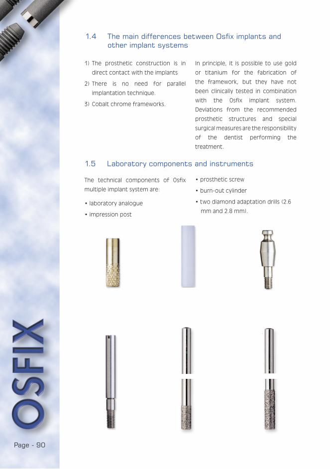
Page - 90
1) The prosthetic construction is in
direct contact with the implants
2) There is no need for parallel
implantation technique.
3) Cobalt chrome frameworks.
1.4 The main differences between Osfix implants and other implant systems
In principle, it is possible to use gold
or titanium for the fabrication of
the framework, but they have not
been clinically tested in combination
with the Osfix implant system.
Deviations from the recommended
prosthetic structures and special
surgical measures are the responsibility
of the dentist performing the
treatment.
1.5 Laboratory components and instruments
The technical components of Osfix
multiple implant system are:
• laboratory analogue
• impression post
• prosthetic screw
• burn-out cylinder
• two diamond adaptation drills (2.6
mm and 2.8 mm).

Page - 91
YOU ARE IN:2. CALIBRATION OF CASTING PROCESS IN DENTAL LABORATORIES
In long-span constructions and precise
cobalt chrome casting, it is very
important to determine the right
casting process and to standardise on
it. Every laboratory should calibrate for
investment material, oven and casting
processes.
The following elements affect the final
result of casting:
1) investment material
2) oven and temperature
3) casting process
4) cooling
The oven temperature and casting
process are easy to standardise, but
investment material should be
standardised separately. One method
of doing so is:
• to wax-up an arch that is supported
by three implants
• to sprue normally
• to mix investment powder with
different amounts of expansion
liquid
(initially ± 10% then ± 5%).
The arch that best fits the model allows
the correct amount of expansion liquid
to be determined.
Follow the manufacturer’s instructions for use when pre-
heating cylinder and mixing investment material.
PART I
PART II
1. INTRODUCTION
1.1 Osfix manual
1.2 Osfix implant system
1.3 Osfix dental treatment
1.4 The main differences between Osfix implants and other implant systems
1.5 Laboratory components and instruments
2. CALIBRATION OF CASTING PROCESS IN DENTAL LABORATORIES
3. PREPARATION OF MASTER MODEL
4. BAR RETAINED OVERDENTURE
5. BRIDGE
6. FIXED FULL ARCH BRIDGE
7. DISINFECTION OF THE COMPLETED WORK
PART III
PART IV
PART V

Page - 92
• Screw laboratory analogues to
impression posts.
• Add a drop of glue to the body of
impression post.
• Place impression posts in the
impression.
• Cast the impression in stone.
3. PREPARATION OF MASTER MODEL
• When preparing the lower denture,
reduce the lingual area of the
denture to allow space for
impression posts and impression
material.
• Reinforce the prosthesis with cold
curing acrylic resin.
4. BAR RETAINED OVERDENTURE
4.1 Preparation of the denture for impression taking
• Remove impression posts.
• Cut the impression into sections to
check the fit of the posts.
Fix the model in the articulator.
• Send the denture to the dentist.
• Returned denture with impression.
• Cast the impression in stone.
• Place burn-out cylinders on occlusal
screws and retain in place.
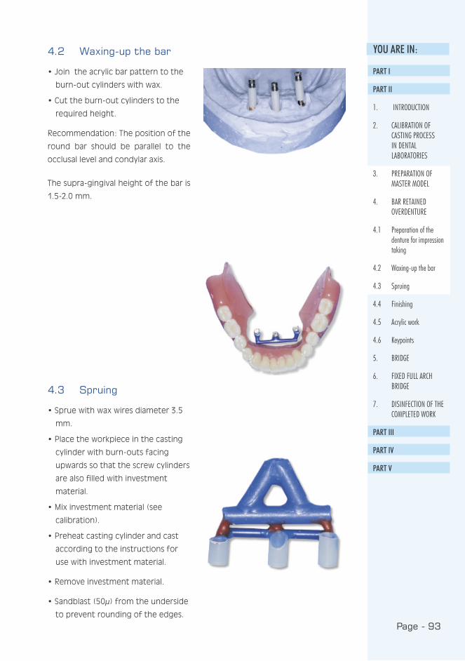
Page - 93
YOU ARE IN:4.2 Waxing-up the bar
• Join the acrylic bar pattern to the
burn-out cylinders with wax.
• Cut the burn-out cylinders to the
required height.
Recommendation: The position of the
round bar should be parallel to the
occlusal level and condylar axis.
The supra-gingival height of the bar is
1.5-2.0 mm.
4.3 Spruing
• Sprue with wax wires diameter 3.5
mm.
• Place the workpiece in the casting
cylinder with burn-outs facing
upwards so that the screw cylinders
are also filled with investment
material.
• Mix investment material (see
calibration).
• Preheat casting cylinder and cast
according to the instructions for
use with investment material.
• Remove investment material.
• Sandblast (50µ) from the underside
to prevent rounding of the edges.
PART I
PART II
1. INTRODUCTION
2. CALIBRATION OF CASTING PROCESS IN DENTAL LABORATORIES
3. PREPARATION OF MASTER MODEL
4. BAR RETAINED OVERDENTURE
4.1 Preparation of the denture for impression taking
4.2 Waxing-up the bar
4.3 Spruing
4.4 Finishing
4.5 Acrylic work
4.6 Keypoints
5. BRIDGE
6. FIXED FULL ARCH BRIDGE
7. DISINFECTION OF THE COMPLETED WORK
PART III
PART IV
PART V
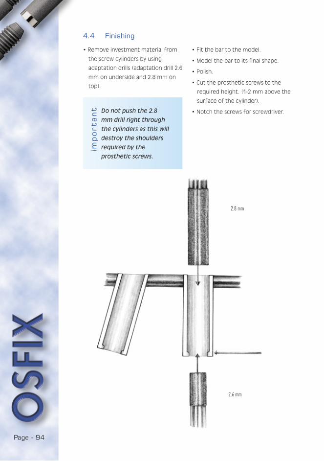
Page - 94
import
an
t
2.8 mm
2.6 mm
4.4 Finishing
• Remove investment material from
the screw cylinders by using
adaptation drills (adaptation drill 2.6
mm on underside and 2.8 mm on
top).
Do not push the 2.8
mm drill right through
the cylinders as this will
destroy the shoulders
required by the
prosthetic screws.
• Fit the bar to the model.
• Model the bar to its final shape.
• Polish.
• Cut the prosthetic screws to the
required height. (1-2 mm above the
surface of the cylinder).
• Notch the screws for screwdriver.
Page - 95
YOU ARE IN:4.5 Acrylic work
• Attach the bar to the model and
position the riders.
• Block-out with wax all but the
retaining parts of the riders and
retention wire.
• Isolate the model.
• Check the fit of the denture.
• Rebase the denture with cold curing
acrylic resin and strengthen with
fibre if necessary.
• Finish the denture.
4.6 Keypoints
• The bar should be parallel to the
condylar axis.
• The prosthetic screws must be at
the right height.
PART I
PART II
1. INTRODUCTION
2. CALIBRATION OF CASTING PROCESS IN DENTAL LABORATORIES
3. PREPARATION OF MASTER MODEL
4. BAR RETAINED OVERDENTURE
4.1 Preparation of the denture for impression taking
4.2 Waxing-up the bar
4.3 Spruing
4.4 Finishing
4.5 Acrylic work
4.6 Keypoints
5. BRIDGE
6. FIXED FULL ARCH BRIDGE
7. DISINFECTION OF THE COMPLETED WORK
PART III
PART IV
PART V

Page - 96
5. BRIDGE
5.1 Waxing-up the framework
• Wax-up the framework to the burn-
out cylinders.
• Model the framework according
to the general principles of bridge
fabrication.
5.2 Spruing
• Sprue, invest and cast following
normal practice in bridge work (see
calibration).
• Remove investment material
residues from the screw cylinders
by sandblasting and using
adaptation drills (2.6 mm on
underside and 2.8 mm on top).
• Fit the framework to the model.
• Model the framework to its final
shape and polish it.
5.3 Finishing the framework
• Sandblast the framework to obtain
retention for acrylic resin.
• Cut prosthetic screws to the
required height (1-2 mm above the
surface of the cylinder).
• Notch the screws for screwdriver.
5.4 Building-up the acrylic teeth
• When modelling teeth consider
the best possible occlusion without
loosing the anatomic shape of the
teeth.
5.5 Keypoints
• The screw cylinders are filled with
investment material.
• Equal distribution of bite force to all
implants.
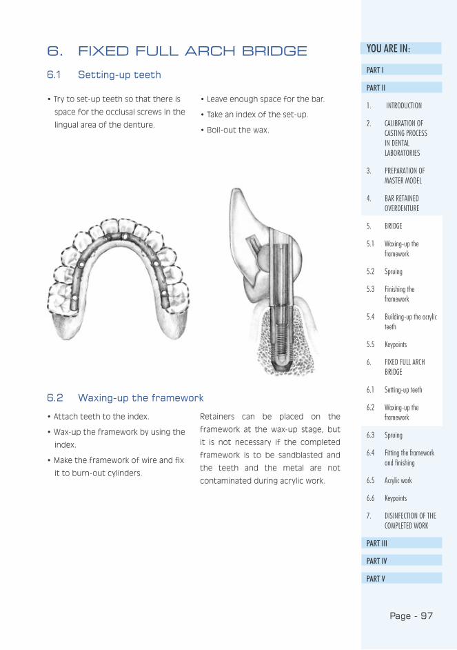
Page - 97
YOU ARE IN:6. FIXED FULL ARCH BRIDGE
6.1 Setting-up teeth
• Try to set-up teeth so that there is
space for the occlusal screws in the
lingual area of the denture.
• Leave enough space for the bar.
• Take an index of the set-up.
• Boil-out the wax.
6.2 Waxing-up the framework
• Attach teeth to the index.
• Wax-up the framework by using the
index.
• Make the framework of wire and fix
it to burn-out cylinders.
Retainers can be placed on the
framework at the wax-up stage, but
it is not necessary if the completed
framework is to be sandblasted and
the teeth and the metal are not
contaminated during acrylic work.
PART I
PART II
1. INTRODUCTION
2. CALIBRATION OF CASTING PROCESS IN DENTAL LABORATORIES
3. PREPARATION OF MASTER MODEL
4. BAR RETAINED OVERDENTURE
5. BRIDGE
5.1 Waxing-up the framework
5.2 Spruing
5.3 Finishing the framework
5.4 Building-up the acrylic teeth
5.5 Keypoints
6. FIXED FULL ARCH BRIDGE
6.1 Setting-up teeth
6.2 Waxing-up the framework
6.3 Spruing
6.4 Fitting the framework and finishing
6.5 Acrylic work
6.6 Keypoints
7. DISINFECTION OF THE COMPLETED WORK
PART III
PART IV
PART V
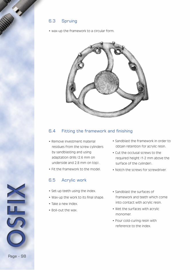
Page - 98
6.3 Spruing
• wax-up the framework to a circular form.
6.4 Fitting the framework and finishing
• Remove investment material
residues from the screw cylinders
by sandblasting and using
adaptation drills (2.6 mm on
underside and 2.8 mm on top).
• Fit the framework to the model.
• Sandblast the framework in order to
obtain retention for acrylic resin.
• Cut the occlusal screws to the
required height (1-2 mm above the
surface of the cylinder).
• Notch the screws for screwdriver.
6.5 Acrylic work
• Set-up teeth using the index.
• Wax-up the work to its final shape.
• Take a new index.
• Boil-out the wax.
• Sandblast the surfaces of
framework and teeth which come
into contact with acrylic resin.
• Wet the surfaces with acrylic
monomer.
• Pour cold-curing resin with
reference to the index.
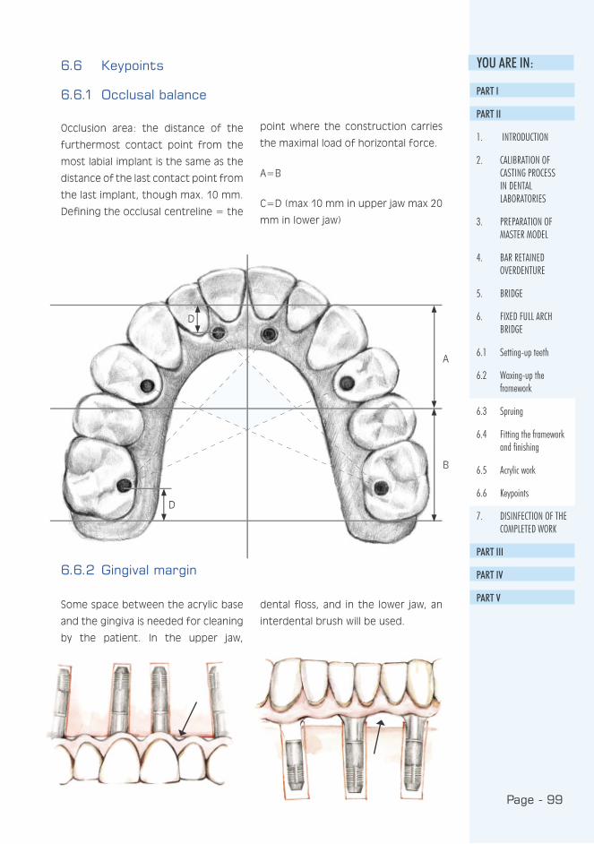
Page - 99
YOU ARE IN:
D
D
A
B
6.6 Keypoints
6.6.1 Occlusal balance
Occlusion area: the distance of the
furthermost contact point from the
most labial implant is the same as the
distance of the last contact point from
the last implant, though max. 10 mm.
Defining the occlusal centreline = the
point where the construction carries
the maximal load of horizontal force.
A=B
C=D (max 10 mm in upper jaw max 20
mm in lower jaw)
6.6.2 Gingival margin
Some space between the acrylic base
and the gingiva is needed for cleaning
by the patient. In the upper jaw,
dental floss, and in the lower jaw, an
interdental brush will be used.
PART I
PART II
1. INTRODUCTION
2. CALIBRATION OF CASTING PROCESS IN DENTAL LABORATORIES
3. PREPARATION OF MASTER MODEL
4. BAR RETAINED OVERDENTURE
5. BRIDGE
6. FIXED FULL ARCH BRIDGE
6.1 Setting-up teeth
6.2 Waxing-up the framework
6.3 Spruing
6.4 Fitting the framework and finishing
6.5 Acrylic work
6.6 Keypoints
7. DISINFECTION OF THE COMPLETED WORK
PART III
PART IV
PART V

Page - 100
7. DISINFECTION OF THE COMPLETED WORK
The dental laboratories and the
dentists should agree on the
disinfection practices. The seating of
implants is always a surgical procedure.
When the prosthesis is carefully
cleaned, infection and complications
are effectively prevented. This has a
direct effect on the patient’s health
and his adaptation to wearing the new
prosthesis.

PART I I ICL IN ICAL
Implant prostheses
and oral hygiene

Page - 102Page - 102
CONTENTS:
1. INTRODUCTION ...................................................105
2. ORAL HEALTH OF AN IMPLANT PROSTHESIS
PATIENT ..............................................................106
2.1 Plaque ...........................................................106
2.2 Tartar............................................................106
2.3 Gingivitis........................................................106
2.4 Treating gingivitis ...........................................107
2.5 Dry mouth .....................................................107
3. ORAL HYGIENE OF AN IMPLANT PROSTHESIS
PATIENT ..............................................................108
3.1 Suitable cleaning instruments .........................108
3.2 Cleaning the implant-fixed bar..........................110
3.3 Cleaning a fixed implant prosthesis...................111
3.4 Cleaning a removable prosthesis .....................113
3.5 Cleaning oral mucosa and
surveying their condition.................................114
3.6 Intensive oral cleaning.....................................114
3.7 Follow-up and maintenance calls.......................114

Page - 104Page - 104
Page - 105
YOU ARE IN:
Traditional dentures are of ten
considered cumbersome and
unpleasant; some people never get
used to them. Users do not feel
comfortable as they always have to
think about how to keep the denture
in place. Everyday functions such as
eating, laughing and speaking may
cause a feeling of insecurity. The
poor stability of dentures may also
cause aching pressure wounds i.e.
sore spots on the mucosa. Implant
treatments offer a solution for
many of the problems involved in
dentures, so the popularity of implant
treatment will continue to increase.
Special attention should be paid to
the promotion of oral health and
the prevention of oral diseases in
this growing group of patients, as in
many cases an implanted mouth will
require the adoption of new cleaning
methods. Therefore, patient guidance
will become essential to enable the
patients to organise their daily oral
hygiene satisfactorily. Insufficient
oral hygiene may, at worst, cause the
loss of an implant. We also need to
provide more information for dental
hygienists, since they need to know
how to clean an implanted mouth for
the elderly or infirm who cannot do
so themselves.
This guide to oral hygiene contains
information on the health and care
of an implanted mouth, and will
help to explain the importance of
oral hygiene to successful implant
treatment. The guide deals with the
cleaning of fixed prostheses as well
as prostheses fitted with a bar. The
guide will describe the oral cleaning
methods, gingivitis, the effect of oral
health on general health, and the
importance of regular follow-up and
maintenance treatment. The guide
may be used when introducing the
concept of implant treatment to
potential patients, or those who have
already had it. It can also be used in
health-care training and in nursing to
provide more information for nursing
personnel, and in planning health
education programmes.
1. INTRODUCTION
1.10.2000
Jaana Turunen
PART I
PART II
PART III
1. INTRODUCTION
2. ORAL HEALTH OF AN IMPLANT PROSTHESIS PATIENT
3. ORAL HYGIENE OF AN IMPLANT PROSTHESIS PATIENT
PART IV
PART V
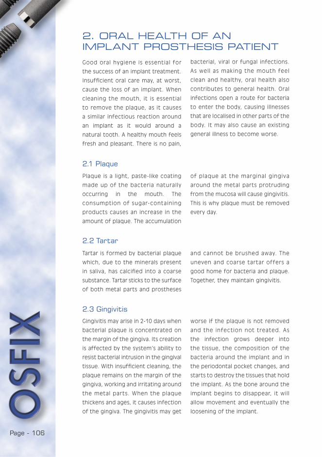
Page - 106Page - 106
2. ORAL HEALTH OF AN IMPLANT PROSTHESIS PATIENT
Good oral hygiene is essential for
the success of an implant treatment.
Insufficient oral care may, at worst,
cause the loss of an implant. When
cleaning the mouth, it is essential
to remove the plaque, as it causes
a similar infectious reaction around
an implant as it would around a
natural tooth. A healthy mouth feels
fresh and pleasant. There is no pain,
bacterial, viral or fungal infections.
As well as making the mouth feel
clean and healthy, oral health also
contributes to general health. Oral
infections open a route for bacteria
to enter the body, causing illnesses
that are localised in other parts of the
body. It may also cause an existing
general illness to become worse.
2.1 Plaque
Plaque is a light, paste-like coating
made up of the bacteria naturally
occurring in the mouth. The
consumption of sugar-containing
products causes an increase in the
amount of plaque. The accumulation
of plaque at the marginal gingiva
around the metal parts protruding
from the mucosa will cause gingivitis.
This is why plaque must be removed
every day.
2.2 Tartar
Tartar is formed by bacterial plaque
which, due to the minerals present
in saliva, has calcified into a coarse
substance. Tartar sticks to the surface
of both metal parts and prostheses
and cannot be brushed away. The
uneven and coarse tartar offers a
good home for bacteria and plaque.
Together, they maintain gingivitis.
2.3 Gingivitis
Gingivitis may arise in 2-10 days when
bacterial plaque is concentrated on
the margin of the gingiva. Its creation
is affected by the system’s ability to
resist bacterial intrusion in the gingival
tissue. With insufficient cleaning, the
plaque remains on the margin of the
gingiva, working and irritating around
the metal parts. When the plaque
thickens and ages, it causes infection
of the gingiva. The gingivitis may get
worse if the plaque is not removed
and the infection not treated. As
the infection grows deeper into
the tissue, the composition of the
bacteria around the implant and in
the periodontal pocket changes, and
starts to destroy the tissues that hold
the implant. As the bone around the
implant begins to disappear, it will
allow movement and eventually the
loosening of the implant.

Page - 107
YOU ARE IN:Symptoms of gingivitis:
• gingiva bleed easily when brushing
or eating hard food
• gingiva are sore and swollen
• the colour of the gingiva changes
from salmon pink to dark red
• bad taste and/or smell in the
mouth.
2.4 Treating gingivitis
Gingivitis is best treated with careful
brushing. Special attention must be
paid to the cleaning of metal parts
protruding from the mucosa at the
margin of the gingiva. Even if
the gingiva are bleeding, brushing
should not be stopped, but the
bleeding area should be brushed
even more carefully. If a week of
careful and regular brushing brings
no improvement, the dentist should
be consulted. Gingivitis breaks out
and heals around the implant just as
it does around a natural tooth.
2.5 Dry mouthDryness of the mouth is usually
caused by a decreased secretion
of saliva. The secretion of saliva
may be reduced by e.g. medicines
used, many general diseases,
deficiency conditions, weakened
general condition, or stress. Saliva
helps keep the mucosa healthy. It
forms a thin film on the surface of the
oral cavity, thus preventing ulcers,
bacterial, viral and fungal infections.
Therefore it is important to keep
the oral mucosa moist. Dryness of
the mouth is relieved by rinsing the
mouth with water and drinking. Saliva
secretion is increased by foods that
require chewing and xylitol products.
There are special products available
for the treatment of a dry mouth.
PART I
PART II
PART III
1. INTRODUCTION
2. ORAL HEALTH OF AN IMPLANT PROSTHESIS PATIENT
2.1 Plaque
2.2 Tartar
2.3 Gingivitis
2.4 Treating gingivitis
2.5 Dry mouth
3. ORAL HYGIENE OF AN IMPLANT PROSTHESIS PATIENT
PART IV
PART V

Page - 108Page - 108
3. ORAL HYGIENE OF AN IMPLANT PROSTHESIS PATIENT
The oral hygiene programme
includes:
1. Cleaning the metal parts/bar and
the space between the prosthesis
and the gingiva
2. Cleaning the prostheses
3. Cleaning the mucosa and surveying
their condition
4. Regular follow-up and maintenance
visits to the dentist
Oral cleaning must be done carefully
and frequently, twice a day would
be ideal. Special attention must be
paid to cleaning the surfaces close to
the tongue as they are more difficult
to clean. There is an ample range of
cleaning instruments on the market,
so everyone should be able to find
something suitable. A rule of thumb is
to have one brush for open surfaces
and another for enclosed spaces. The
success of the cleaning operation
may be checked with colour tablets
and a mirror.
3.1 Suitable cleaning instruments
• toothbrush/electric toothbrush/
special toothbrush
• plastic-coated interdental brush
• special dental floss, floss threaders
if required
• solo brush and other special
brushes
• prosthesis brush for cleaning the
prostheses
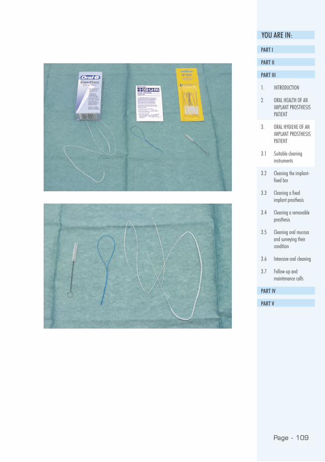
Page - 109
YOU ARE IN:
PART I
PART II
PART III
1. INTRODUCTION
2. ORAL HEALTH OF AN IMPLANT PROSTHESIS PATIENT
3. ORAL HYGIENE OF AN IMPLANT PROSTHESIS PATIENT
3.1 Suitable cleaning instruments
3.2 Cleaning the implant-fixed bar
3.3 Cleaning a fixed implant prosthesis
3.4 Cleaning a removable prosthesis
3.5 Cleaning oral mucosa and surveying their condition
3.6 Intensive oral cleaning
3.7 Follow-up and maintenance calls
PART IV
PART V

Page - 110Page - 110
3.2 Cleaning the implant-fixed bar
A small, soft brush is most
suitable for the cleaning of
the bar (picture 1). It is vital
that the brushing motion
consists of small back and
for th movements at the
margin of the gingiva where
the gingiva and the metal
parts meet.
An interdental brush or
special dental floss may
be used for cleaning the
spaces in the bar. In addition
to brushing, toothpaste or
prosthesis paste may be
used in cleaning. Polishing
toothpastes should not be
used.
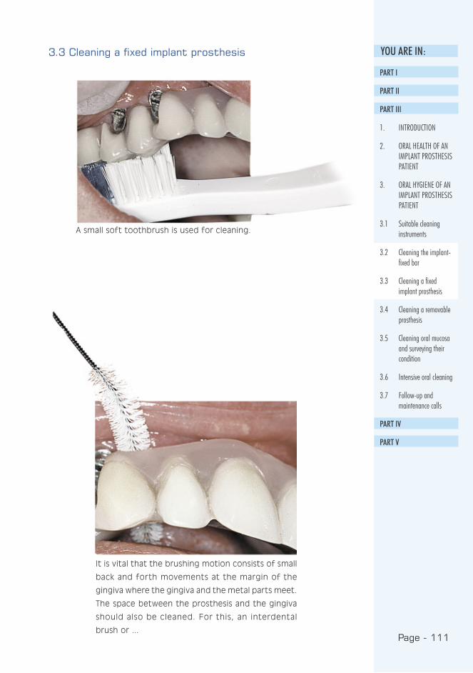
Page - 111
YOU ARE IN:3.3 Cleaning a fixed implant prosthesis
A small soft toothbrush is used for cleaning.
It is vital that the brushing motion consists of small
back and forth movements at the margin of the
gingiva where the gingiva and the metal parts meet.
The space between the prosthesis and the gingiva
should also be cleaned. For this, an interdental
brush or ...
PART I
PART II
PART III
1. INTRODUCTION
2. ORAL HEALTH OF AN IMPLANT PROSTHESIS PATIENT
3. ORAL HYGIENE OF AN IMPLANT PROSTHESIS PATIENT
3.1 Suitable cleaning instruments
3.2 Cleaning the implant-fixed bar
3.3 Cleaning a fixed implant prosthesis
3.4 Cleaning a removable prosthesis
3.5 Cleaning oral mucosa and surveying their condition
3.6 Intensive oral cleaning
3.7 Follow-up and maintenance calls
PART IV
PART V
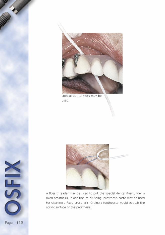
Page - 112Page - 112
special dental floss may be
used.
A floss threader may be used to pull the special dental floss under a
fixed prosthesis. In addition to brushing, prosthesis paste may be used
for cleaning a fixed prosthesis. Ordinary toothpaste would scratch the
acrylic surface of the prosthesis.
Page - 113
YOU ARE IN:3.4 Cleaning a removable prosthesis
Cleaning the prosthesis is as important
as cleaning natural teeth, as tartar,
plaque and an invisible film of bacteria
build up on the surface of the
prosthesis in the same way as they
do on natural teeth. Clean prostheses
feel and look better in the mouth,
and the whole mouth feels fresher.
Insufficiently cleaned prostheses
may cause various bacterial, viral and
fungal infections in the oral cavity.
A dental prosthesis must be cleaned
carefully at least twice a day and
rinsed after every meal.
There are special brushes for cleaning
loose prostheses, with a wide head
for cleaning large areas and a narrow
head to enter small holes. A sof t
brush is used to clean the mucosa.
Prosthesis paste, washing-up liquid
or mild soap may be used for
cleaning. Prostheses must not be
cleaned with ordinary toothpaste as
it would scratch their acrylic surface.
Effervescent tablets may also be used
for removing discolouration.
The prostheses are washed with
lukewarm water, as very hot water
may damage them. Special attention
should be paid to the surfaces that
are in contact with the mucosa.
The mucosa are cleaned with a soft
toothbrush before the prosthesis
is replaced. Clean prostheses are
replaced into a clean mouth.
When the prostheses are not in the
mouth, they have to be kept moist
e.g. in a glass of water or wrapped
in damp paper in a watertight box.
If allowed to dry out, the prosthesis
may twist and become unusable.
If the prosthesis rubs or feels
uncomfortable, the dentist should be
contacted. Likewise, if the prosthesis
suffers damage, if a prosthetic part or
a screw has loosened or if the contact
pieces, i.e. the bar’s riders, have been
damaged, the dentist should, once
again, be consulted.
PART I
PART II
PART III
1. INTRODUCTION
2. ORAL HEALTH OF AN IMPLANT PROSTHESIS PATIENT
3. ORAL HYGIENE OF AN IMPLANT PROSTHESIS PATIENT
3.1 Suitable cleaning instruments
3.2 Cleaning the implant-fixed bar
3.3 Cleaning a fixed implant prosthesis
3.4 Cleaning a removable prosthesis
3.5 Cleaning oral mucosa and surveying their condition
3.6 Intensive oral cleaning
3.7 Follow-up and maintenance calls
PART IV
PART V
Page - 114Page - 114
3.5 Cleaning oral mucosa and surveying their condition
It is beneficial to rinse the mouth
several times a day. In addition
to cleaning, the brushing of the
tongue, the gingiva and the palate
improves circulation and keeps the
tissue healthy. The prosthesis will hold
better in a clean mouth. Cleaning
offers the perfect opportunity to
inspect the condition of the mucosa.
If you feel or notice something
unusual in the mouth, e.g. changes in
the mucosa, coating, flushed areas,
pain, swelling, bad smell or taste etc.
you should contact your dentist.
3.6 Intensive oral cleaning
If oral cleaning is found to be
insufficient, it may be temporarily
intensified with chlorhexidine
(Corsodyl®) rinsing. This may not be
used for long-term cleaning, as the
efficient antibacterial chlorhexidine
may have adverse an effect on the
balance of the oral bacteria if used
continuously, which could permit
fungal infections to flourish. The
effect of mouthwashes other than
chlorhexidine is insignificant. If they
are preferred, a product containing
no fluoride should be chosen. The
use of chlorhexidine or ordinary
mouthwashes does not replace
brushing, but rather supplements it.
Chloride hexine may cause a brown
discolouration on the prosthesis
and the surface of the tongue. The
discolouration may be decreased by
applying the product locally using an
interdental brush or cotton stick. If
necessary, the discolouration may be
removed from the prosthesis by the
dental technician. The discolouration
of the tongue will be removed by
itself.
3.7 Follow-up and maintenance calls
The most common reasons for losing
an implant are insufficient oral
hygiene at home, and the neglecting
of regular maintenance inspections.
Implant patients should attend
regular maintenance consultations.
Maintenance calls are, preferably,
made annually: the structures will
be dismounted if necessary, and the
components serviced. Simultaneously,
the success of oral hygiene may be
controlled and the methods revised
when necessary. The condition of
the implants is also followed with
X-rays. A regular and careful follow-up
will lengthen the life of an implant
prosthesis.


CONTENTS:
1. INTRODUCTION ....................................................121
2. THE PATIENT FOR SEDATION..................................122
2.1. Examining the patient ....................................122
2.2. Clinical anatomy.............................................122
3. BENZODIAZEPINES
3.1. Operating mechanism ....................................124
3.2. Half-life .........................................................124
3.3. Pharmacodynamics ........................................125
3.4. Pharmacokinetic anomalies .............................125
4. THE COMMERCIAL DRUGS
4.1. Selecting a suitable drug................................126
4.2. Diazepam .....................................................126
4.3. Midazolam.....................................................128
4.4. Administration equipment...............................129
4.5. First aid equipment........................................130
5. MONITORING THE PATIENT ....................................132
5.1. Blood pressure monitors ................................132
5.2. Pulse oximetry...............................................133
5.2.1. Monitoring during sedation.......................133
5.2.2. Emergency situations .............................134
5.2.3. Sources for default..................................134
6. INTRAVENOUS SEDATION IN PRACTICE ..................135
6.1. Cannulating the vein in the crook of the arm ....135
6.2. Administering the drug and observing the effects136
6.3. Recovery from sedation..................................137
6.3.1. Oxygen saturation ...................................137
6.3.2 Flumazenil................................................138
7. COMPLICATIONS ..................................................140
7.1. Local complications........................................140
7.2 Hypoxia..........................................................140
7.3. Fainting ........................................................140


7.4. Psychogenic complications .............................141
7.5. Other complications.......................................141
7.6. Legal aspects................................................142
7.7. Conclusions...................................................143
7.8. Instructions to patients.................................144

Page - 120
Page - 121
YOU ARE IN:
OSFIX implant treatment involves major
operations. Thus the patients
frequently require sedation. To reach
an adequate and accurate effect,
these drugs have to be administered to
the vein. This is known as intravenous
sedation (sedative medication
introduced through the vein). It is
not general anaesthesia. However,
even intravenous sedation involves
risks which must be recognised, and
due precautions for treating possible
complications must be made.
Why should we use intravenous
sedation, facing its intrinsic risks, rather
than oral sedation?
This is a question which fellow dentists
frequently ask the author of this study.
To answer it we need to look at some
principles: orally, a useful dosage of
diazepam is 10 mg for young and
adults, 5 mg for children. Smaller doses
will not produce a useful sedation. The
dosages per os for midazolam are 7.5
to 15 mg.
Given orally, in the majority of patients
these doses create good sedation,
sufficient for a normal procedure. The
problem is that a minority of patients
will not experience any sedative effect
with these doses. In the case of a
nervous patient, their experience of
the treatment will be most unpleasant.
Another minority of patients will
become oversedated with these doses,
to the point that they are practically
in a very deep anaesthesia during
the whole procedure, which severely
impairs the dentist’s work. Recovery
from the procedure can then take
several hours, which will paralyse the
operations of the dental surgery for
those hours.
Although the basic doses for
intravenous sedation are 10 mg of
diazepam and 5 mg of midazolam (note
the difference in the efficiency ratio
of midazolam), the individual amount
for the patient is titrated to the exact
point through intravenous dosage.
Hence oversedation or undersedation
will be extremely rare. There will be no
problems with the procedures and the
patient’s recovery is swift.
For the patient, intravenous sedation
is a necessary alternative in dental
care. It should nevertheless not involve
risks which outweigh the advantages.
The dentist and the dental surgery
assistant must ensure that they have
sufficient training for and a good
command of this procedure. These
skills must also be regularly rehearsed
and developed. This is the only way to
avoid emergencies and complaints.
The purpose of these instructions
is to provide a theoretical basis for
the understanding of intravenous
sedation, but the practical application
of the procedure necessitates manual
training and a demonstrated command
of the subject.
1. INTRODUCTION
PART I
PART II
PART III
PART IV
1. INTRODUCTION
2. THE PATIENT FOR SEDATION
3. BENZODIAZEPINES
4. THE COMMERCIAL DRUGS
5. MONITORING THE PATIENT
6. INTRAVENOUS SEDATION IN PRACTICE
7. COMPLICATIONS
PART V

Page - 122
A careful examination of the patient’s
medical history is a precondition of
safe intravenous sedation. An example
of an easily completed medical history
form is enclosed. This form should be
further complemented by an interview,
as this gives the best contact with the
patient. It is important to define the
patient’s weight and height so that the
correct dosages can be chosen. The
interview also provides the opportunity
to draft a psychological profile of the
patient. The dentist should aim at
establishing the level of anxiety and
the level of self-control in the patient.
If the patient is extremely nervous
and he/she reacts to the slightest
stimulus during the examination, the
administration of intravenous sedation
should be seriously reconsidered. In
addition to consent from the patient,
intravenous sedation requires also the
surgeon’s command of this method
of treatment and its complications.
Intravenous sedation is not suitable
for a patient who:
• has an acute lung disorder
• has a serious functional disorder of
the liver
• has an operational disorder of the
kidneys
• is taking steroid medication
• is using psychiatric medication,
including benzodiazepines
• has a serious muscular weakness,
Myastenia gravis
• has a serious neurological illness
• suffers from an alcohol problem or
a drug addiction
• is of advanced age or underage
• exhibits a sensitivity to
benzodiazepine (extremely rare)
• is pregnant, extreme care should
also be taken with breast-feeding
mothers
In the event of any doubt that
this treatment might be suitable for
the patient, it is advised to consult
his/her practising general physician.
Despite the consultation it must be
remembered, though, that the
responsibility for the sedation lies with
the dentist.
2. THE PATIENT FOR SEDATION
2.1 Examining the patient
2.2 Clinical anatomy
When undertaking intravenous
sedation it is important to know the
anatomy of the vascular system of
the hand. Suitable sites for injection
for dental sedation are the cubical
fossa and the dorsum of the hand.
The advantages of the cubical fossa
are the large veins that are easy
to puncture, and the fact that the
injection is less painful than when
puncturing the dorsum of the hand.
Eventual haematomas caused by the
injection are less visible in the cubical
fossa than the dorsum of the hand,
and they are easily covered with
clothes. The dorsum of the hand may,
Page - 123
YOU ARE IN:at times, be the only possibility when
the patient’s clothing prevents the use
of the cubical fossa or when no visible
vein is found in the cubical fossa.
Use of the cubical fossa does present
the risk of accidentally allowing the
cannula to penetrate an artery, or
of causing arterial bleeding into the
tissues. There may also be problems
in the liquid flow of the cannula when
the patient bends their arm.
The disadvantages of the dorsum of
the hand are, above all, smaller veins,
more sensitive site of injection and
the visibility of the bruises.
The complications of cannulation are:
• bleeding from the injection area to
surrounding tissues (haematoma)
• thrombus and infection of the vein
(thromboflebitis)
• tenderness of the site of injection
• the possibility of the cannula
penetrating an artery and
• the possibility of injecting the drugs
into arterial circulation
The complications of an intra-arterial
injection are very severe; in the worst
case they may lead to the loss of
the entire limb or a serious circulation
disorder therein. Therefore, patients
sedated intravenously must always be
connected to a saline drip.
When a free-flowing liquid infusion
tube is connected to the cannula
which is placed in an artery, a fast
and powerful blood intrusion to the
infusion tube and upwards all the way
to the infusion bottle or bag can be
observed. At this point there can be
no doubt about the cannula being
misplaced. When the cannula alone is
placed in the vein it is not possible to
be absolutely certain that it is securely
in the vein and not in an artery.
PART I
PART II
PART III
PART IV
1. INTRODUCTION
2. THE PATIENT FOR SEDATION
2.1 Examining the patient
2.2 Clinical anatomy
3. BENZODIAZEPINES
4. THE COMMERCIAL DRUGS
5. MONITORING THE PATIENT
6. INTRAVENOUS SEDATION IN PRACTICE
7. COMPLICATIONS
PART V
Page - 124
It is important to know the operating
mechanisms of the applied drugs.
In the clinical pharmacology of
benzodiazepines the main issue is
pharmacodynamics, or how the drug
works in the body. Although it is easy
to measure the drug plasma levels
for most drugs, estimating the drug’s
concentration at the receptor sites
is extremely difficult. Many drugs are
attached to receptors and their plasma
levels do not necessarily correlate
with their effect. This often causes
problems in defining the correct
dosage. This is also the case for
benzodiazepines. Nevertheless it is
apparent that there is no clear
correlation between benzodiazepine
plasma levels and their clinical effect.
Hence it follows that the calculation
of pharmacokinetic parameters from
plasma levels is not clinically relevant.
This applies e.g. to the half-life of
benzodiazepines. The very effect of
benzodiazepines is based on their
connecting to receptors in the brain.
Therefore their clinical effect has only
a very vague correlation with their
plasma levels.
3. BENZODIAZEPINES
3.1 Operating mechanism
3.2 Half-life
Half-life means the time taken for the
plasma concentration to decrease by
50%. It is important to note that this
is not the time the drug takes to
disappear from the body, nor is it the
time when the drug’s effect can be
seen in the body. The terms ‘long half-
life, ‘short half-life may sometimes
be confused with ‘long-acting’ and
‘short-acting’, therefore the meaning
of each should be kept clearly in mind.
For instance the half-life of diazepam
is several dozens of hours (24-48),
whereas its active sedation time is only
a few dozen minutes.
The following steps shall be observed
when dosing intravenous drugs:
1) The uptake or absorption phase,
which is the time taken to inject
the drug, in the case of drugs
dosed straight into the vein. The
absorption phase of oral drugs is
long and it depends on the uptake
of the drug.
2) The distribution phase, during
which the drug is distributed into
tissue components according to its
properties, e.g. the liquid system
or fatty tissues.
3) The elimination phase which
begins when a balance between
plasma and the other tissues
of the body has been reached.
Subsequently, the drug is
eliminated through liver
metabolism or kidney secretion
according to the drug’s half-life.
The patient’s clinical recovery will
be enhanced once the drug is
eliminated from his body.

Page - 125
YOU ARE IN:
All diazepines have the following four
characteristics:
1) Hypnotic or sleep inducing
2) Anxiolytic (sedative, eliminating
anxiety, calming)
3) Muscle relaxant effect
4) Prevention and reduction of
convulsions.
The action of benzodiazepines is based
on the stasis of benzodiazepine
receptors. These receptors are found
in the central nervous system. The
receptors are very specific to the
agonists and antagonists of
benzodiazepine. They are not receptive
to other sedative agents such as
barbiturates.
3.3 Pharmacodynamics
3.4 Pharmacokinetic anomalies
In overdose cases where the patient
has taken massive amounts of
diazepam (as much as 400 times
the usual dose), plasma levels are
extremely high for several days. The
patient will, however, recover clinically
to the extent that he is fully alert and
able to leave the hospital considerably
sooner than the elimination time of
the drug.
It is important to understand that the
clinical maximum effect of a drug does
not have a correlation with its plasma
level. This is quite apparent when a
drug is administered intravenously:
while the drug’s plasma level is still
increasing, the patient is much more
sedated and tired than when the
plasma level is already decreasing
(compare with getting drunk and
sobering up).
The lack of correlation between
drowsiness and drug plasma levels
is also evident when the patient is
prescribed diazepam for continued
use. The patients tend to be tired
during the first few days, even though
the plasma level is still rising over
the following days. The steady state
level, in which the elimination and
further administration are in balance,
is reached much later. The effect of
a given dose depends more on the
speed of increase of the plasma level
than the plasma level itself.
PART I
PART II
PART III
PART IV
1. INTRODUCTION
2. THE PATIENT FOR SEDATION
3. BENZODIAZEPINES
3.1 Operating mechanism
3.2 Half-life
3.3 Pharmacodynamics
3.4 Pharmacokinetic anomalies
4. THE COMMERCIAL DRUGS
5. MONITORING THE PATIENT
6. INTRAVENOUS SEDATION IN PRACTICE
7. COMPLICATIONS
PART V
Page - 126
The ideal sedating agent should
possess the following properties:
1) Sufficient sedative and anxiolytic
properties
2) Amnesia or blocking memory for
the duration of the procedure
3) Easy administration
4) No irritating effects on veins or
tissues
5) Short and speedy recovery
6) No effect on cardiovascular or
respiratory systems
7) Low toxicity
8) No side-effects
9) Compatibility with other drugs.
Both diazepam in an emulsified form
and midazolam closely approach the
above requirements. Therefore, they
are widely used in connection with
dental procedures as well as e.g.
with gastroenterological procedures.
The commonest drugs used in dental
procedures are diazepam, midazolam
and flumazenil.
4. THE COMMERCIAL DRUGS
4.1 Selecting a suitable drug
4.2 Diazepam
Diazepam is available in 2 ml ampoules,
each containing 10 mg diazepam.
Diazepam is available both in a water-
alcohol solution, a combination which
does irritate veins, and in an oil-water
emulsion which does not have an
irritating effect and which is the only
acceptable solution for intravenous
sedation. In many countries the trade
name of the latter is Stesolid Novum
5mg/ml injection liquid and it is
packed in 2 ml ampoules, meaning
that one ampoule contains 10 mg
diazepam. In Stesolid Novum, the
diazepam is dissolved in an oil base. The
organic solvents used in conventional
parentheral diazepam products have
been found to cause unpleasant
symptoms and pain in 78% and
thrombophlebitis in 30% of cases
when injected into the vein, thus
they may be considered unsuitable
for intravenous sedation. The
corresponding frequencies for the
Stesolid Novum injections are 5.3
and 1.1%. Stesolid Novum is ready
for injection and it may also be
administered to small peripheral veins.
Diazepam should never be injected into
the muscle because of very insecure
absorption.
The official indication of the drug is
premedication before the procedure.
Dosage for premedication is 0.1-0.2
mg diazepam/kg intravenously. A rule
of thumb for the maximum dosage of
diazepam in dental procedures is that
doses over 20 mg may be used only
for exceptionally lengthy procedures.
The initial dose of diazepam should
never exceed 20 mg. It should also
be borne in mind that the clinical
effect for elderly and weak patients
is usually reached with smaller doses.
This means in practice that elderly
patients should be administered only
Page - 127
YOU ARE IN:ca. 2.5 mg diazepam at a time and
allowed a few minutes for the effects
to become apparent after each dose.
Other facts to remember are the
contraindications and the fact that
diazepam impairs the tolerance for
alcohol, sedatives and sleeping
tablets.
The effect of diazepam on the central
nervous system is localised in the
subcortical areas and the reflexes. Its
half-life in the plasma is 24-48 hours.
This long half-life causes a risk of the
drug accumulating in the body if the
doses are repeated before an earlier
dose has been eliminated. If a patient
uses diazepam daily for his medication,
a dose given in the vein may lead to
respiratory depression. Recording the
drugs used in the patient’s medical
history is therefore imperative.
The main metabolite of diazepam
is desmethyldiazepam, which has a
half-life of 100 hours. Yet diazepam
may interact with any drug that has
a depressant effect on the central
nervous system. It can potentiate
the effect of other hypnotics and
sedatives on the brain. It may also
increase the effects of alcohol. The
use of diazepam is also problematic if
the patient is taking anti-depressant
medication. The slow elimination of
diazepam and its metabolites may
cause an exceptionally strong reaction
if other sedatives are taken before
complete elimination, this carries a risk
of danger. On the other hand, these
problems occur quite rarely, even
though diazepam is a very common
drug.
Following oral administration,
diazepam is absorbed rapidly. A single
dose of 10-15 mg gives a plasma
concentration of 0.2-0.3
micrograms/ml within 2 hours. The
elimination of the drug is initially rapid
but it slows down into a total half-life
of 1-2 days.
Following intravenous administration
(10-15 mg), the plasma concentration
of 1 microgram/ml is reached within 4
minutes and a strong sedative effect
is immediate. The concentration then
falls to 0.25 micrograms/ml per hour
and the clinical effect is reduced at
the same rate. The main effect of the
intravenous dose falls within the first
hour, thereafter the effect resembles
that of an oral dose. To reach the
same concentrations orally as are
created intravenously for the first
hour, extremely high doses of the drug
would be needed.
PART I
PART II
PART III
PART IV
1. INTRODUCTION
2. THE PATIENT FOR SEDATION
3. BENZODIAZEPINES
4. THE COMMERCIAL DRUGS
4.1 Selecting a suitable drug
4.2 Diazepam
4.3 Midazolam
4.4 Administration equipment
4.5 First aid equipment
5. MONITORING THE PATIENT
6. INTRAVENOUS SEDATION IN PRACTICE
7. COMPLICATIONS
PART V

Page - 128
Midazolam is available in 5 ml ampoules
containing 5 mg midazolam or a
content of 1 mg/ml, and in 3 ml
ampoules containing 15 mg midazolam
or a content of 5 mg/ml. The latter
have been intended solely for use
as a general anaesthetic and are not
suitable for dental applications. The
former, weaker solution should be used
for dental procedures as it enables the
safe titration of the dose.
Midazolam is sold under the trade name
Dormicum. Midazolam can form water-
soluble salts with acids which provide a
well-tolerated water-soluble injection
liquid. The drug has a short duration
and is well suited for premedication.
Midazolam typically shows a rapid
onset and short duration due to a fast
metabolism. Due to its low toxicity, the
therapeutic scale of midazolam is wide.
A short-term anterograde amnesia is
experienced after intravenous dosage,
and patients show a clear tendency
towards dozing off once the desired
sedation level has been reached. The
elimination half-life is 1.5-3 hours.
The elimination half-life of the principal
metabolite, alfahydroxy midazolam,
is shorter than that of midazolam.
With elderly people, the half-life of
midazolam may become as much
as three times longer. Therefore an
intravenous dosage should be titrated
against the patient’s response.
The official indication of midazolam
is intravenous basic sedation in
connection with diagnostic or surgical
procedures carried out under local
anaesthesia. The initial dose is 2.5 mg
5-10 minutes before the operation.
Additional doses of 1 mg may be given
if necessary. Doses greater than 5 mg
are generally not required to create the
desired response. The easiest means
of dosage is to titrate 1 mg of the
drug through a cannula every second
minute and then follow up for the
response.
The effect of midazolam is so strong
and individual that there is a risk
of serious side effects. A respiratory
depression may turn into the
discontinuation of respiration which,
undetected, leads to cardiac arrest.
This is a great risk with elderly or weak
patients, and resuscitation equipment
should always be on hand.
Midazolam interacts with the following
drugs: analgesics, sleeping drugs,
anxiolytes, antidepressants,
neuroleptics, simeditine and
4.3 Midazolam

Page - 129
YOU ARE IN:
Disposable syringe: for premedication
with midazolam, the most practical
size is 5 ml, and for diazepam, 2 ml.
Needle: needles are needed for the
transfer of the drug from the ampoules
to the syringe. Ideal needles are as
wide and long as possible, e.g. ones
with a Luer connector.
Cannula: in intravenous sedation, the
patient should also have a venal
cannula. The ideal would be one with
three entrances, which facilitates a
possible change of infusion bag. The
cannula needle may be very thin as only
salt solution needs to be transferred
through the cannula, a thin needle will
also make the cannulation procedure
much more pleasant. A suitable width
of cannula is 20 G (gauge) which
corresponds to a diameter of 1 mm,
and a sufficient length for the needle
is 30 mm. This size of cannula will
allow the transfer of 50 ml liquid per
minute which is quite sufficient in this
case. With a thin cannula, the injection
is painless and succeeds well. Venal
irritation is also much smaller than
when using a larger cannula.
Infusion tube: The simplest transfer
tube with an infusion chamber,
restriction valve and a Luer lock for
connecting the cannula.
Infusion liquid: A physiological sodium
chloride liquid (0.9%), available at
the pharmacy, is used in intravenous
sedation. It comes in both glass and
4.4 Administration equipment
PART I
PART II
PART III
PART IV
1. INTRODUCTION
2. THE PATIENT FOR SEDATION
3. BENZODIAZEPINES
4. THE COMMERCIAL DRUGS
4.1 Selecting a suitable drug
4.2 Diazepam
4.3 Midazolam
4.4 Administration equipment
4.5 First aid equipment
5. MONITORING THE PATIENT
6. INTRAVENOUS SEDATION IN PRACTICE
7. COMPLICATIONS
PART V
erythromycin. All these drugs
contribute to a longer active period or
a stronger response. It must especially
be noted that midazolam should be
administered with special caution to
elderly people and weak patients,
and to patients suffering from an
obstructive pulmonary disease, chronic
kidney deficiency or cardiac
insufficiency.

Page - 130
plastic containers. A volume of half
a litre is quite sufficient for sedation
purposes. The rate of the infusion
should be fast at the beginning of
sedation, and when the sedation level
is sufficient, the rate of the infusion
may be set to one drop per 2-3
seconds (=1 ml/min).
Surgical tape: The cannula is attached
so as to permit no movement. A
strong adhesive tape, preferably in a
y-form bandage, should be employed.
Pharmacies have a wide range of
various surgical tape materials packed
in rolls, so finding a suitable one for
attaching the cannula should cause no
problems.
Venous stasis: A venous stasis is
attached above the cannulation site
to raise the veins. It should direct the
pressure to prevent the return of the
blood through the veins but to allow
the blood pressure to fill the limb.
4.5 First aid equipment
Additional oxygen is the most frequent
supplement required in intravenous
sedation. An oxygen cylinder is an
absolute necessity and no procedures
should be started if there is not
enough oxygen for several hours’
administration. Nasal cannula are ideal
for administering oxygen during the
procedure as an oxygen mask cannot
be used.
Precautions against respiratory arrest
shall be made with a emergency
resuscitator, “Ambu”, that is connected
to the oxygen. During the procedure
the sedationist must have both the
possibility and the ability to perform
an endothracheal intubation for the
patient if needed. This makes
intravenous sedation a suitable next
step after becoming experienced with
nitrous oxide. The above mentioned
resuscitation methods must be learnt
before a permit to use nitrous oxide
will be granted.
The resuscitation drugs listed in the
general dental studies should be
available at the surgery. These are 1)
epinephrine, 2) diazepam, 3) atropine,
4) cortisone, and various liquids to
solve the above, as well as the syringes
and needles to administer them. In
addition to these, intravenous sedation
procedures require certain drugs
primarily intended to cure respiratory
depression and to support the
cardiovascular system. These drugs
are:
• nalorphin (Nalorfin®), which cures
the respiratory depression caused
by opiates;
• flumazenil (Lanexat®) to impede
the benzodiazepine receptors and
thus cure the respiratory
depression caused by
benzodiazepines. Flumazenil is a
benzodiazepine antagonist and it is
available in 5 ml ampoules. They
contain 0.5 mg of the drug or 0.1
mg/ml. It is important to always
have the antagonist within reach
in case any problems should arise
during the procedures.

Page - 131
YOU ARE IN:• doxazepram; (Dopram®), which
stimulates the respiratory centre in
the brain;
• salbutamol (Ventoline®) opens the
pulmonary tubes e.g. in connection
with status asthmaticus;
• etilephrine (Effortil®) which is used
to increase the volume per minute
of the heart and to increase blood
pressure.
All the above mentioned drugs are in
injection form and require the correct
training in addition to learning their
properties from the available literature.
It is of the utmost importance that
all necessary emergency/resuscitation
drugs are within reach of the dental
surgeon performing the operation,
and that the expiry dates of ampoules
are duly followed. Moreover, the
ampoules should not be opened until
immediately before use as an opened
ampoule will not keep.
PART I
PART II
PART III
PART IV
1. INTRODUCTION
2. THE PATIENT FOR SEDATION
3. BENZODIAZEPINES
4. THE COMMERCIAL DRUGS
4.1 Selecting a suitable drug
4.2 Diazepam
4.3 Midazolam
4.4 Administration equipment
4.5 First aid equipment
5. MONITORING THE PATIENT
5.1 Blood pressure monitors
5.2 Pulse oximetry
6. INTRAVENOUS SEDATION IN PRACTICE
7. COMPLICATIONS
PART V
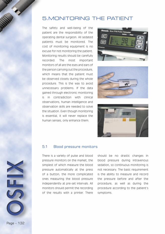
Page - 132
The safety and well-being of the
patient are the responsibility of the
operating dental surgeon. All sedated
patients must be monitored. The
cost of monitoring equipment is no
excuse for not monitoring the patient.
Monitoring results should be carefully
recorded. The most important
monitors of all are the eyes and ears of
the person carrying out the procedure,
which means that the patient must
be observed closely during the whole
procedure. This is the way to avoid
unnecessary problems. If the data
gained through electronic monitoring
is in contradiction with clinical
observations, human intelligence and
observation skills are needed to solve
the situation. Even though monitoring
is essential, it will never replace the
human senses, only enhance them.
5.1 Blood pressure monitors
5.MONITORING THE PATIENT
There is a variety of pulse and blood
pressure monitors on the market, the
simplest of which measure the blood
pressure automatically at the press
of a button, the more complicated
ones measuring the blood pressure
independently at pre-set intervals. All
monitors should permit the recording
of the results with a printer. There
should be no drastic changes in
blood pressure during intravenous
sedation, so continuous monitoring is
not necessary. The basic requirement
is the ability to measure and record
the pressure before and after the
procedure, as well as during the
procedure according to the patient’s
symptoms.
Page - 133
YOU ARE IN:5.2 Pulse oximetry
The functions of the body depend on
a continuous intake of oxygen. This
vital supply has been secured by
many means, the most important of
which is the ability of haemoglobin to
bind oxygen. The amount of oxygen
bound in haemoglobin depends on
the prevailing oxygen pressure, but
an essential fact is that the
dependence is not linear but creates a
co-ordination curve forming a gentle
S. The amount of oxyhaemoglobin,
oxygenated haemoglobin, in the total
amount of haemoglobin, is called
oxygen saturation, measured as a
percentage. The flat end of the oxygen
dissociation curve of haemoglobin
ensures good oxygen saturation across
a wide variation of oxygen pressure.
On the other hand, the steep fall of
the curve enables the quick delivery
of oxygen to the areas with oxygen
pressure characteristic of certain
tissues.
Oximetry measures oxygen saturation,
or the percentage of oxyhaemoglobin.
It can also be measured in a laboratory
test from an arterial blood sample,
but nowadays oximetry normally refers
to a non-invasive monitoring system
in which the monitoring occurs
continually through the skin. The
oximeter is usually connected to a
finger, but other monitoring sites such
as the earlobe are also suitable.
Pulse oximetry was developed for
clinical use in the mid-1970s in Japan.
During the 1980s, this monitoring
system became extremely popular
and, during the last few years, it
has, in many countries, even been
considered compulsory in the control
of general anaesthesia. Since 1986,
pulse oximetry has become so popular
worldwide that it is considered by many
to be the most important monitoring
system in anaesthesia.
Pulse wave oximetry also utilises the
information contained in the pulse
wave. Even though it used only to
function in the monitoring of the
timing of the saturation, the pulse wave
printed on the screen is becoming a
regular feature of the equipment. The
size of the pulse wave is subject to
great variation according to various
factors and thus it reflects the changes
in blood flow at the monitoring site.
PART I
PART II
PART III
PART IV
1. INTRODUCTION
2. THE PATIENT FOR SEDATION
3. BENZODIAZEPINES
4. THE COMMERCIAL DRUGS
5. MONITORING THE PATIENT
5.1 Blood pressure monitors
5.2 Pulse oximetry
6. INTRAVENOUS SEDATION IN PRACTICE
7. COMPLICATIONS
PART V
5.2.1 Monitoring during sedation
The most feared of possible
emergencies in connection with
sedation is a sudden lack of oxygen.
Therefore pulse oximetry is a safety
factor which enables the quick
detection of a sudden lack of oxygen
and the counteraction of its
consequences. Attention must be paid
to a continual decrease of saturation
before it reaches the stage of an
actual lack of oxygen. Pulse oximetry is
particularly applicable at the onset of
sedation as it is during this phase that
most changes in saturation occur. Even
extensive local anaesthesia creates
more decreases in saturation than is
Page - 134
commonly believed. Saturation may
decrease in cases where anaesthesia
has to be complemented with
intravenous analgesics or sedatives.
The situation is usually relieved with
the application of oxygen.
oxygen pressure. Therefore, the shape
of the dissociation curve should always
be considered when interpreting the
oxygen saturation values.
In pulse oximetry, the saturation and
pulse rate values require a pulsating
circulation, but the values remain
reliable even during poor peripheral
circulation.
There would be plenty of use for
pulse oximetry when estimating the
danger of sudden emergencies and the
corresponding efficiency of corrective
measures. Lack of oxygen is connected
with many acute illnesses and damage
and therefore constitutes a concrete
risk factor. A pulse oximeter also
immediately displays the effectiveness
or ineffectiveness of the corrective
measures. If the patient is transferred
to a hospital, the monitoring should
be continued as unexpected changes
in the patient’s condition may arise in
emergencies.
There are certain sources of default
within pulse oximetry and pulse wave
oximetry, although as such they are
quite reliable methods.
The absorption of red light is not
specific to oxyhaemoglobin, as the
same phenomenon is created by
the bonding of carbon monoxide to
haemoglobin. This is visible, e.g., in a
patient who is a heavy smoker.
Pulse oximetry measures oxygen
saturation which decreases only
slightly, although there may be a
considerable decrease in the venal
5.2.2 Emergency situations
5.2.3 Sources for default
Page - 135
YOU ARE IN:
Before beginning intravenous
sedation, the dentist should make
sure that all necessary resuscitation
PART I
PART II
PART III
PART IV
1. INTRODUCTION
2. THE PATIENT FOR SEDATION
3. BENZODIAZEPINES
4. THE COMMERCIAL DRUGS
5. MONITORING THE PATIENT
5.1 Blood pressure monitors
5.2 Pulse oximetry
6. INTRAVENOUS SEDATION IN PRACTICE
6.1 Cannulating the vein in the crook of the arm
6.2 Administering the drug and observing the effects
6.3 Recovery from sedation
7. COMPLICATIONS
PART V
6. INTRAVENOUS SEDATION IN PRACTICE
equipment and drugs are close at
hand, that there is sufficient oxygen in
the oxygen cylinder and that the drugs
have not passed their expiry dates.
6.1 Cannulating the vein in the crook of the arm
Before the patient arrives, the
following equipment should be
prepared:
• a 5 ml syringe
• a large needle (G 21) for the suction
of the drug
• intravenous cannula
• alcohol swab
• drugs
• venous stasis
• infusion fluid package
• infusion tube
The patient’s weight should be
determined beforehand or, if it has
not been, it should be verified at
this point. The drug is nevertheless
dosed primarily according to individual
reactions and only secondarily in
accordance with the patient’s weight.
The patient is placed into an almost
supine position, his blood pressure is
taken and the probe for the pulse
oximeter is attached, then the initial
values for blood pressure and oxygen
saturation are recorded.
The cannulation can also be carried
out completely without pain with an
emulsion ointment or plaster (Emla ®)
to numb the skin for the cannulation
procedure. The plaster is more practical
for cannulation purposes as it is
individually packed and can be
attached by the patient or his parent
in an agreed place. The anaesthetic
effect begins after 1 hour and thus
to be useful the product should be
supplied in advance, for the patient
to apply at home. More detailed
information on the product can be
found in the national Pharmaca.
A venous stasis is placed on the
patient’s arm to provide good visibility
of the veins. When fitting the venous
stasis, it should be remembered that
the pressure should not be so great
that arterial circulation in the arm is
obstructed. Following this, the cannula
is attached and fixed to the skin with
adhesive tape.
The salt solution is placed in the
infusion stand and the chamber of
the intravenous line is filled with the
liquid. The whole length of the tube
is checked carefully for air bubbles.
The infusion tube is attached to the
cannula and for a while the infusion
valve is set to allow maximum flow. This
is to ensure that the flow is free and
the surrounding tissue is not swelling
as a sign of paravenous infusion. At this
point it will be evident if the injection
has punctured an artery, as blood will
rush up the injection tube.
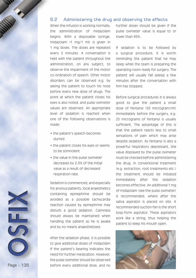
Page - 136
When the infusion is working normally,
the administration of midazolam
begins. With a disposable syringe,
midazolam (1 mg/1 ml) is given in
1 mg doses. The doses are repeated
every 2 minutes. A conversation is
held with the patient throughout the
administration, on any subject, to
observe the impairment of the motor
co-ordination of speech. Other motor
disorders can be observed e.g. by
asking the patient to touch his nose
before every new dose of drugs. The
point at which the patient closes his
eyes is also noted, and pulse oximeter
values are observed. An appropriate
level of sedation is reached when
one of the following observations is
made:
• the patient’s speech becomes
slurred
• the patient closes his eyes or seems
to be somnolent
• the value in the pulse oximeter
decreases by 2-3% of the initial
value as a result of decreased
respiration rate.
Sedation is commenced, and especially
for anxious patients, local anaesthetics
containing epinephrine should be
avoided as a possible tachycardia
reaction caused by epinephrine may
disturb a good sedation. Calmness
should always be maintained when
handling the patient as he is awake
and by no means anaesthetised.
After the sedation phase, it is possible
to give additional doses of midazolam
if the patient’s bearing indicates the
need for further medication. However,
the pulse oximeter should be observed
before every additional dose, and no
further doses should be given if the
pulse oximeter value is equal to or
lower than 95%.
If sedation is to be followed by
a surgical procedure, it is worth
reminding the patient that he may
sleep while the team is preparing the
operating room ready for surgery. The
patient will usually fall asleep a few
minutes after the conversation with
him has stopped.
Before surgical procedures it is always
good to give the patient a small
dose of fentanyl (50 microgram/ml)
immediately before the surgery, e.g.
25 micrograms of fentanyl is usually
sufficient. The advantage of this is
that the patient reacts less to small
sensations of pain which may arise
despite sedation. As fentanyl is also a
powerful respiratory depressant, the
value displayed by the pulse oximeter
must be checked before administering
the drug. In conventional treatment
(e.g. extraction, root treatments etc.)
the treatment should be initiated
immediately after the sedation
becomes effective. An additional 1 mg
of midazolam (see the pulse oximeter)
is recommended, where after the
saliva aspirator is placed on site. A
recommended suction fan is the short
loop-form aspirator. These aspirators
work like a string, thus helping the
patient to keep his mouth open.
6.2 Administering the drug and observing the effects
Page - 137
YOU ARE IN:
Oxygen saturation is monitored closely,
both during the procedure and during
the recovery from sedation. If oxygen
saturation falls below 90%, it is
important to immediately check the
patient’s respiration movements and
openness of airways. It is also
diagnostic to know if the decrease is
sudden or slow. In some cases, the
reason may be local to the point of
measurement: it should be checked
that the probe does not apply so much
pressure to the monitoring site that it
obstructs circulation. In such an event,
the probe should be moved to another
finger, but only after the exclusion of
genuine oxygen desaturation. Should
you suspect a malfunction of the
probe, use your own finger to test the
function of the probe.
If the value remains unchanged,
airways are open and the patient is
breathing, additional oxygen should
immediately be given to the patient.
A nasal cannula and a regular 3-10 l
oxygen cylinder (e.g. AGA) are suitable,
providing that there is enough oxygen
for several hours’ use. The
administration of additional oxygen
will repair, almost without exception,
the onset of hypoxia. If the respiratory
depression is caused by
benzodiazepines and the low oxygen
saturation is not increased by oxygen
administration, the patient should
be intravenously administered some
flumazenil (Lanexat 0.1 mg/ml à 5 ml).
This drug can be dosed in 0.1 mg
i.e. 1 ml portions which are repeated
every minute until the oxygenation
has returned to normal. The dosage
may rise to a maximum of 1 mg (10
ml).
If respiration depression is caused
by benzodiazepines, return to normal
oxygenation is very fast and will occur
during the very first doses.
As flumazenil is a benzodiazepine
antagonist, it blocks the same
receptors as those to which
benzodiazepines are attached.
Therefore flumazenil may be given in
a sufficiently small amount to prevent
an eventual respiration depression, but
not to lose the sedation. The procedure
may then continue normally.
PART I
PART II
PART III
PART IV
1. INTRODUCTION
2. THE PATIENT FOR SEDATION
3. BENZODIAZEPINES
4. THE COMMERCIAL DRUGS
5. MONITORING THE PATIENT
6. INTRAVENOUS SEDATION IN PRACTICE
6.1 Cannulating the vein in the crook of the arm
6.2 Administering the drug and observing the effects
6.3 Recovery from sedation
7. COMPLICATIONS
PART V
6.3 Recovery from sedation
6.3.1 Oxygen saturation
Page - 138
In addition to treating complications,
flumazenil may be used to end the
sedation of a patient after a short
procedure. The patient may be given
0.05 mg per 5 minutes of flumazenil,
until he can walk without assistance.
As the half-life of flumazenil is shorter
than that of benzodiazepine,
resedation may occur within 2-3 hours,
the patient and his escort should be
notified of this possibility.
The initial dose of 0.2 mg flumazenil
is administered through the cannula
while it is still in place in the cubical
fossa. It must be noted here that the
cannula should remain in place during
the whole procedure and must not
be removed until the patient is fully
recovered. A few seconds after being
given flumazenil, the patient is likely to
open his eyes. When the patient is
fully awake he is given permission
to sit up and, after a few further
minutes, he is also given written
instructions for recovery which are
also referred to orally. The instructions
should essentially forbid driving and
the consumption of alcohol. At this
stage, there is no point in explaining
excessively complicated things to the
patient. The instructions will order the
patient to rest for the following day.
The advantages of the benzodiazepine
antagonist are:
1) an efficient emergency drug for
oversedated patients
2) full co-operation of the patient
3) a safer recovery period
The possibility of using flumazenil as
an antagonist in overdose cases makes
it an extremely important drug for
securing the sedation process. It must
be kept within reach whenever a
patient is sedated. Some patients are
very sensitive to benzodiazepines,
and in such cases an antagonist
may even prove to be a life-saving
drug. Elderly patients are much more
sensitive than the young to the effect
of benzodiazepines. In cases where
general anaesthesia is contraindicated
due to the patient’s respiratory illness,
intravenous sedation is the only
method to enable certain procedures,
and flumazenil ensures that the
sedation is safe. A general rule to
observe in the case of elderly patients
is not to send them home immediately
after treatment with intravenous
sedation, but rather to arrange for
overnight monitoring for them in the
ward.
When the patient is sedated, his
level of consciousness has decreased
and this may encumber complicated
procedures, e.g. the preparation of
a dental crown. A suggestion is to
perform the unpleasant procedures
immediately at the beginning of
sedation. Once the stage is reached
when the patient need no longer be
sedated but co-operative, he is given
flumazenil until he can contribute to
the procedure (e.g. the fitting of
occlusion and dentures).
Patients who have undergone
treatment under intravenous sedation
and have been given flumazenil to
6.3.2 Flumazenil
Page - 139
YOU ARE IN:
eliminate the sedation can sit and
stand normally. It must, however, be
remembered that they remain sedated
and cannot fully look after themselves.
It is crucial to remember that the
effective time of flumazenil is shorter
than that of midazolam and, in theory,
the sedation with eventual respiratory
depressions may return, even though
the long duration of dental procedures
makes it highly unlikely. The presence
of an escort is, even in these cases,
absolutely necessary. The escort gives
the patient a feeling of security
and someone to talk to about the
experience.
PART I
PART II
PART III
PART IV
1. INTRODUCTION
2. THE PATIENT FOR SEDATION
3. BENZODIAZEPINES
4. THE COMMERCIAL DRUGS
5. MONITORING THE PATIENT
6. INTRAVENOUS SEDATION IN PRACTICE
6.1 Cannulating the vein in the crook of the arm
6.2 Administering the drug and observing the effects
6.3 Recovery from sedation
7. COMPLICATIONS
PART V
After the procedure, the patient may
be sent home 3 hours after the last
dose of midazolam. He should be
provided with an adult escort. Both
the patient and his escort should be
reminded of the written instructions
which the patient received on his
previous visit; the main points being
that the patient’s ability to observe
traffic is impaired in the 12 hours
to follow, and that he should not
consume alcohol during this time, as it
would increase the effect of the drugs
and vice versa. Some people may show
unpredictable individual reactions. The
patient should be made aware of the
dentist’s office and home telephone
numbers in case any help is needed
after the treatment.

Page - 140
Intravenous injections may produce
a reaction at the injection site, later
turning into a thrombophlebitis. This is
an inflammatory reaction found at the
injection site: redness of skin, swelling
and pain. The vein may be blocked
due to the infection (thrombus),
but although painful, this is not a
dangerous condition. Haematomas can
also found at the injection site. They are
generally a result of damage occurring
in the vein, and the consequent
bleeding into the surrounding tissues.
To avoid paravenous injections, please
ensure that the needle really is in the
vein. The most reliable way to control
this is to connect the infusion bottle
to the cannula. If the cannulation has
failed, do not try the same vein again
but use another vein which should be
as large as possible. With appropriate
technique, an extravenous injection
will be observed almost as soon as
it has occurred. The cannula is then
removed and a compression bandage
is tied on the site, eventually lifting
the hand slightly to avoid swelling. If a
thrombophlebitis is developing, it will
heal itself in a few days, or one to two
weeks.
There are descriptions in medical
literature of the broken tip of a
metallic needle or the plastic parts of a
cannula ending up in the bloodstream.
The breaking of a venal cannula and
the introduction of a loose part
into circulation is, without exception,
poor medical practice caused by the
cannulation technique, and as such
will lead to prosecutions and claims.
7. COMPLICATIONS
7.1 Local complications
7.2 Hypoxia
A serious hypoxia is a very rare
complication of diazepam or
midazolam, and it occurs most
frequently as a consequence of an
obstruction in the respiratory
passages. When the sedation is too
strong, the airways are not held open
naturally. The patient will perform
breathing movements but no air is
passing. During a partial obstruction,
the patient sounds as if he is snoring.
Drugs may interact to emphasise
the respiratory depression effect of
diazepam. Oversedation and overdose
will also cause respiratory depression.
It is important to titrate the sedation
dose to the exact point. As mentioned
above, pulse oximetry of the patient is
of the utmost importance.

Page - 141
YOU ARE IN:
7.4 Psychogenic complications
Patients who are under psychiatric
medication or treatment are not suited
to intravenous sedation. There are
some descriptions of paradoxical
excitement which is mainly found in
children, but in individual cases there
have been aggressive reactions even
with adults. The only way to deal
with the situation seems to be to
discontinue the procedure. A more
common reaction is a decrease in the
patient’s conscious inhibition, so that
the patient becomes very talkative
and says things he would not normally
mention. When initiating sedation, it is
good to lead the conversation towards
harmless topics, as the amnesia caused
by the drug may further distort the
recollection on the contents of the
conversation. Some cases have been
recorded in which patients undergoing
intravenous sedation have had sexually
coloured illusions, the worst of which
have even led to prosecution of the
sedating physician. This is why it is very
important that all monitoring is set up
before the sedation. This particularly
applies to EKG monitoring; the patient
should not, whilst under sedation,
undergo procedures which he would
not expect a dentist to perform. For
security reasons, it is also vital that
another member of staff is present
during the whole of the treatment
process: at the initiation of sedation,
during the procedure and during the
recovery period. A good precaution
for the dentist’s legal protection is
to make a video recording of the
procedure and to file the tapes.
PART I
PART II
PART III
PART IV
1. INTRODUCTION
2. THE PATIENT FOR SEDATION
3. BENZODIAZEPINES
4. THE COMMERCIAL DRUGS
5. MONITORING THE PATIENT
6. INTRAVENOUS SEDATION IN PRACTICE
7. COMPLICATIONS
7.1 Local complications
7.2 Hypoxia
7.3 Fainting
7.4 Psychogenic complications
7.5 Other complications
7.6 Legal aspects
7.7 Conclusions
7.8 Instructions to patients
PART V
7.3 Fainting
An extremely nervous patient may
produce a vasovagal collapse, either
before or during the administration of
the drug. In this case the procedure
should immediately be discontinued
and normal instructions against
fainting should be followed. First, the
limbs are raised. No dental procedure
should be carried out during this
appointment. The patient is given
a new appointment and it should
be considered whether part of the
diazepam or midazolam should be
given beforehand per os for instance
1-2 hours before the appointment.
7.5 Other complications
There is a small group of patients who,
after being given a few milligrams of
diazepam or midazolam, will fall into
deep sleep, as the dose does not
depend on the patient’s weight. A
large patient may reach deep sedation
while a small patient who weighs very
little may take a much larger dose. The
latter group may look the dentist in
the eye after a 10 mg dose and say,
“It doesn’t make any difference at all”.
What must be remembered, however,
is that the patient may be sedated
despite his claims to the contrary. This
case would call for psychomotor tests
such as asking the patient to touch his
Page - 142
nose. It is likely that he cannot perform
this trick. Requesting a signature on
a piece of paper would easily reveal
the depth of the sedation. Increasing
the dose for an extremely resistant
patient may lead to a quick and deep
drop into oversedation. Therefore, a
key rule is not to give the patient
more than 10 mg midazolam or 20 mg
diazepam intravenously.
The intravenous administration of
midazolam has few cardiovascular
effects. The problems i.e. intra-arterial
injections are easily avoided when the
following is kept in mind:
• Only use a vein that is clearly
visible, and only after placing the
cannula should the infusion tube be
connected.
• Always ask how the patient feels
both at the beginning of the
infusion and when giving the first
drugs. Ask whether he can feel any
local pain and if not, all is well.
An intra-arterial infection may cause
an ischemy and necrose of the distal
part of the whole arm. In case of acute
respiratory or oral infection causing
the obstruction of airways, intravenous
sedation is contraindicated. Acute
dental patients are ill-suited to
intravenous sedation. Thus acute
processes must first be brought under
control through draining or antibiotics,
only then can the procedure be
undertaken under local anaesthesia
and intravenous sedation.
7.6 Legal aspects
Sedation creates operational disorders
in the patient’s memory which may
cause misunderstandings, leading at
their worst to prosecution of the
dentist. Therefore, certain principles
should be adopted:
• the most important principle is to
explain all procedures diligently to
the patient, and to give him written
instructions.
• careful recording of the patient’s
medical history
• the patient must come with a reliable
escort
• the procedure must be suitable for
intravenous sedation
• the staff must be trained
• emergency equipment and drugs
must be close at hand and effective
• if teeth need to be extracted during
the procedure, the patient must be
informed of this in advance, before
the procedure
• no payments shall be made at the
sedation appointment
• the patient shall be told what
preparations the procedure will require
and what he has to observe after the
procedure.

Page - 143
YOU ARE IN:When these instructions are followed,
everything is likely to go well. If
problems do arise with a patient,
they can usually be solved in a quiet
and informative discussion with the
patient. If not, it might be useful
for the dentist to contact a more
experienced colleague. The patient
should also be offered a meeting with
this more experienced colleague. If
legal procedures must be taken, the
primary task is to contact the lawyer
of the dentist or the dentists’ union.
PART I
PART II
PART III
PART IV
1. INTRODUCTION
2. THE PATIENT FOR SEDATION
3. BENZODIAZEPINES
4. THE COMMERCIAL DRUGS
5. MONITORING THE PATIENT
6. INTRAVENOUS SEDATION IN PRACTICE
7. COMPLICATIONS
7.1 Local complications
7.2 Hypoxia
7.3 Fainting
7.4 Psychogenic complications
7.5 Other complications
7.6 Legal aspects
7.7 Conclusions
7.8 Instructions to patients
PART V
7.7 Conclusions
Intravenous sedation is, both for the
dentist and his patient, a pleasant,
efficient and safe means of treating
anxiety problems. The basis for this
security is, however, the appropriate
skills of the staff. Therefore, in the
conditions prevailing in the northern
European dental education tradition,
instructions could be given where the
dentist should first be qualified in
using nitrous oxide, thus already having
a command and practice of patient
handling, intravenous injections and
endothracheal intubations. Thereafter
the dentist could attend an
intravenous sedation course and
commence an apprenticeship with
a colleague who is experienced in
sedation. Individual sedation should
be commenced only when the dentist
has thorough knowledge of this
anesthesiological method. The skill
should also be continuously
maintained. Endothracheal intubation
exercises should not be practised only
once, but this life-saving procedure
in a severe complication should be
practised annually at a central hospital.
Neither should intravenous sedation
remain a measure to be taken only
when the treatment cannot be carried
out in any other way. The skills to
carry out the sedation would then be
too weak and the result could be an
extremely difficult patient that would
test the skills of even an experienced
sedationist. The best way to maintain
sedation skills is to use the method
constantly.
Page - 144
7.8 Instructions to patients
Instructions for an extensive dental
procedure:
• Please have an X-ray and the
laboratory tests taken within a
week of the control appointment.
Please bring the X-ray pictures
and laboratory results to the next
appointment.
• The procedure will be made
under local anaesthesia and using a
sedative premedication. Therefore,
no pain or fear is experienced
during the treatment.
• Please dress lightly: a short-sleeved
shirt and loose-fitting trousers.
Do not use make-up or other
chemicals on the face. Nail varnish
should be removed. Wrist watch,
rings, necklaces and other jewellery
should be left at home if you are to
undergo a surgical procedure.
• EATING AND DRINKING IS FORBIDDEN
4 HOURS PRIOR TO THE
APPOINTMENT. Therefore please
take the medication you may have
been prescribed exactly 4 hours
before the appointment.
• You should be accompanied by an
adult escort who will ensure your
safe journey home and who will be
available to you until the following
morning.
• During the 24 hours after the
procedure YOU MUST NOT:
-leave home alone
-drink alcohol
-drive a vehicle
-go to work
• Please also make sure that you have
informed the operating dentist
of all your possible illnesses and
medications.
• A feverish cold or cough as well
as other feverish illnesses, until
they have been cured, will prevent
any treatments. Neither can the
treatment be carried out in the
case of an open labial herpes.
• If you have to cancel your
appointment, please do so 2 weeks
before the agreed time
• Immediately before coming to the
appointment, please use the toilet.


Page - 146
PART V CONTENTS:
LIST OF SCIENTIFIC PUBLICATIONS ................................148
ANIMAL STUDY ............................................................151
CLINICAL STUDY ..........................................................181
FOLLOW-UP STUDY......................................................173
OVERLOADING.............................................................181
COATING......................................................................193
Page - 148
- 1998
• Luotio*, Ryhänen, Petrelius,
Kotilainen: The Clinical Follow-up
of The Osfix Dental Implant
System: pilot results after one
year:
- 22nd Annual Conference of
European Prosthodontic
association (EPA).
28.-29.8.1998, Turku, Finland
- The XIV Congress of European
association for Cranio.
Maxillofacial Surgery,
1.-5.9.1998, Helsinki, Finland
- 4th European Symposium on
Oral Surgery, 1.-4.10.1998,
Berlin, Germany
• Vallittu and Luotio: Effect of
cobalt-chromium surface casting
on resistance to deflection
fatigue and surface hardness
of titanium. Int J Prosthod
1996:9:527-32
• Luotio: A Finnish implant system
by Osfix Oy, Hammasteknikko
1998:4:4-6 (in Finnish)
• Luotio, Kotilainen, Petrelius,
Ryhänen: Clinical observations on
dental implant system “Osfix”.
Clinical Implantology and
Stomatology (St. Petersburg,
Russia) 1998:3:14-21 (in Russian)
1999
• Luotio*: Mandibular complete
denture stabilization with dental
implants: 1st Baltic symposium on
osseointegrated implants. Riga,
Latvia 6.-7.10.1999.
• Luotio*: Osfix System: Florida
Academy of Dental Implantology,
15.-23.10.1999, USA
2000
• Luotio*, Kotilainen, Vesanen,
Hanhela: Immediate implantation
with sandblasted titanium
implants; an animal experiment:
- 6th joint symposium Rostoc-
Riga, 26.-27.5.2000 Riga,
Latvia.
- EACMFS congress, 5.-9.9.2000
Edinburgh, Scotland- EAO 9th
annual scientific congress,
14.-16.10.2000 Amsterdam,
The Netherlands
- 20th National and 13th
International Congress -
Sociedad Espanola de
Implantes, 15.-17.6.2000,
Alicante, Spain.
• Luotio*, Ryhänen, Petrelius,
Kotilainen, Hanhela: The Osfix
dental implant system - a 3-years
follow-up study. Otrais Latvijas
zobarstniecibas kongress
4.-5.10.2000 Riga, Latvia
SCIENTIFIC PUBLICATIONS

Page - 149
YOU ARE IN:
• Luotio, Skagers*, Zigurs, Jansen,
Salms, Lappi, Danilovs: First
experience with BiOsfix dental
implants. Otrais Latvijas
zobarstniecibas kongress
4.-5.10.2000 Riga, Latvia.
• Luotio, Kotilainen, Petrelius,
Ryhänen, Hanhela: Fast
Hundertprozentig / Success
nearly a hundred per cent.
Implantologie Journal
2000:1:69-75
• Luotio, Kotilainen, Vesanen,
Hanhela: Auf die tionstiefe
kommt es ein. Tierexperimentelle
Studie zur Sofortimplantation mit
Osfix- Titanimplantaten.
Implantologie Journal
2000:2:90-96
• Luotio, Turunen, Hanhela: Besser
lachen und kauen. Implantate,
Lebensqualität und Mundhygiene.
Implantologie Journal
2000:3:68-74
• Luotio, Kotilainen, Petrelius,
Ryhänen, Hanhela: La eficacia
de un sistema de implantes
osteointegrados. Exito en la casi
totalidad de los casos. Labor
dental clinica 2000:4:121-123
• Luotio, Kotilainen, Vesanen,
Hanhela: La implantacion
inmediata con implantes de
titano Osfix. Un experimento con
animales de laboratorio. Labor
dental clinica 2000:5:158160
2001
• Luotio, Kotilainen, Petrelius,
Ryhänen, Hanhela: The OSFIX
Dental Implant System - A
Three-year Follow-up Study.
Independent Dentistry
2001:1:73-76
• Luotio, Stenberg, Kotilainen,
Vuoristo, Mäntylä: Evaluation of
coatings for dental implant
frameworks. Independent
Dentistry 2001:2:67-70
• Luotio, Kotilainen, Hanhela,
Jatkola, Halonen, Lappi: The
behaviour of Osfix implant
components in overload
situations. Independent Dentistry
2001:3:101-105
PART I: Clinical
PART II: Laboratory
PART III: Hygiene
PART IV: Sedation
PART V: Studies
ANIMAL STUDY
CLINICAL STUDY
FOLLOW-UP STUDY
OVERLOADING
COATING

Page - 150

Page - 151
YOU ARE IN:
PART I: Clinical
PART II: Laboratory
PART III: Hygiene
PART IV: Sedation
PART V: Studies
ANIMAL STUDY
CLINICAL STUDY
FOLLOW-UP STUDY
OVERLOADING
COATING
ANIMAL STUDY:THE EFFECT
OF SANDBLASTING ON OSTEOINTEGRATION
K. Luotio DDS, PhD, 1, 2, H. Vesanen DDS, 1, R. Kotilainen Prof, DDS, PhD, 1,
M. Hanhela MSc. 2
1 University of Kuopio, Institute of Oral Surgery
2 Osfix Oy / Ltd, Box 14, FIN-47201 Elimäki, Finland
1.1 ABSTRACT
In this study, a total of 40 aluminium oxide sandblasted, custom made and
cast pure grade-2 titanium implants were inserted into the mandibular bones
of 10 beagle dogs. Characterisation of the implant surface was performed
by standard SEM-methods. X-ray measurements and histomorphometrics were
used to analyse the osteointegration properties. The surface of the titanium
after sandblasting shows extensive roughening and the surface consists of
70-80 % titanium and 20-30 % aluminium, both as oxides. The success rate of
immediate implantation was limited, but all of the implants, none of which were
more than 1mm above the bone margin, met the success criteria. Examination
by conventional microscopy proves that the majority (65 %) of the implant
surface is in contact with bone.
Page - 152
The purpose of this study was to
characterise the surface of pure
titanium which has been abraded
or roughened with aluminium oxide
sandblasting and to chart the progress
of the osteointegration of sandblanted
titanium implants in beagle dogs. A
further aim was to determine the
depth at which dental implants should
be inserted in the mandible bone to
achieve optimal osteointegration.
1.2 AIM OF STUDY
1.3 MATERIALS AND METHODS
In this study, a total of 40 implants
were inserted into the mandibular
bone of 10 beagle dogs. The implants
were custom made and cast using pure
grade-2 titanium and sulphur-based
investment material (Rematitan®).
Before implantation, the fixtures were
sandblanted using aluminium oxide
and then sterilised in an autoclave. All
the implants were of the dimensions
3.0 x 8.0 mm.
The animals used in this study were
adult beagle dogs. Ten animals, males
and females, of mean age 11.1 months
(range 10-12 months) and of mean
weight 11.5 kg (range 9.5-14.5 kg)
formed the study group. The
extractions were performed under
intravenous anaesthesia with
pentobarbital sodium (Mebunat®,
Orion, Finland), 20mg/kg. The implants
were inserted in the mandible after
bilateral extraction of the last posterior
teeth, two implants per quadrant into
the alveolar sockets of both roots.
The surgical procedure was done
under the aseptic conditions in which
extractions are normally performed.
Neither high-level surgical aseptics nor
flap elevations were used.
Post-operatively, procain penicillin
with dihydrostreptomycin, 1ml/10kg
(Compiotic®, Pfizer, Switzerland), was
administered subcutaneously daily for
one week. A soft diet was maintained
for the first 7 days, followed by a
normal diet until the predetermined
healing period of 3 months had passed.
The implants were not loaded during
the 3-month healing period. During
this period the animals were housed
in a facility designed for long-term
animal care.
After 3 to 4 months healing period the
animals were put down using a lethal
barbiturate injection, the lower jaw
was sectioned with forceps in order
to isolate the pieces of bone with
implants and penultimate molar. Each
block was placed in 10 % formaline
solution.
The samples were examined
radiologically immediately after
isolating the sections of implanted
bone. The x-ray film used in this
study was technical fine grain film
(Kodak Industrex). The images were
photographically transformed into
positive pictures, which were analysed
by measurement. The dimensions of
integration and bone pocket formation
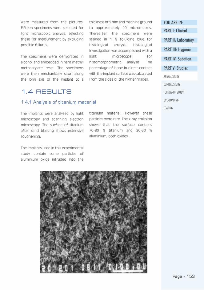
Page - 153
YOU ARE IN:
PART I: Clinical
PART II: Laboratory
PART III: Hygiene
PART IV: Sedation
PART V: Studies
ANIMAL STUDY
CLINICAL STUDY
FOLLOW-UP STUDY
OVERLOADING
COATING
were measured from the pictures.
Fifteen specimens were selected for
light microscopic analysis, selecting
these for measurement by excluding
possible failures.
The specimens were dehydrated in
alcohol and embedded in hard methyl
methacrylate resin. The specimens
were then mechanically sawn along
the long axis of the implant to a
thickness of 5 mm and machine ground
to approximately 10 micrometres.
Thereafter, the specimens were
stained in 1 % toluidine blue for
histological analysis. Histological
investigation was accomplished with a
light microscope for
histomorphometric analysis. The
percentage of bone in direct contact
with the implant surface was calculated
from the sides of the higher grades.
1.4 RESULTS
1.4.1 Analysis of titanium material
The implants were analysed by light
microscopy and scanning electron
microscopy. The surface of titanium
after sand blasting shows extensive
roughening.
The implants used in this experimental
study contain some particles of
aluminium oxide intruded into the
titanium material. However these
particles were rare. The x-ray emission
shows that the surface contains
70-80 % titanium and 20-30 %
aluminium, both oxides .
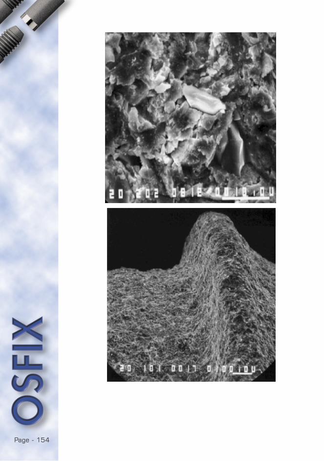
Page - 154
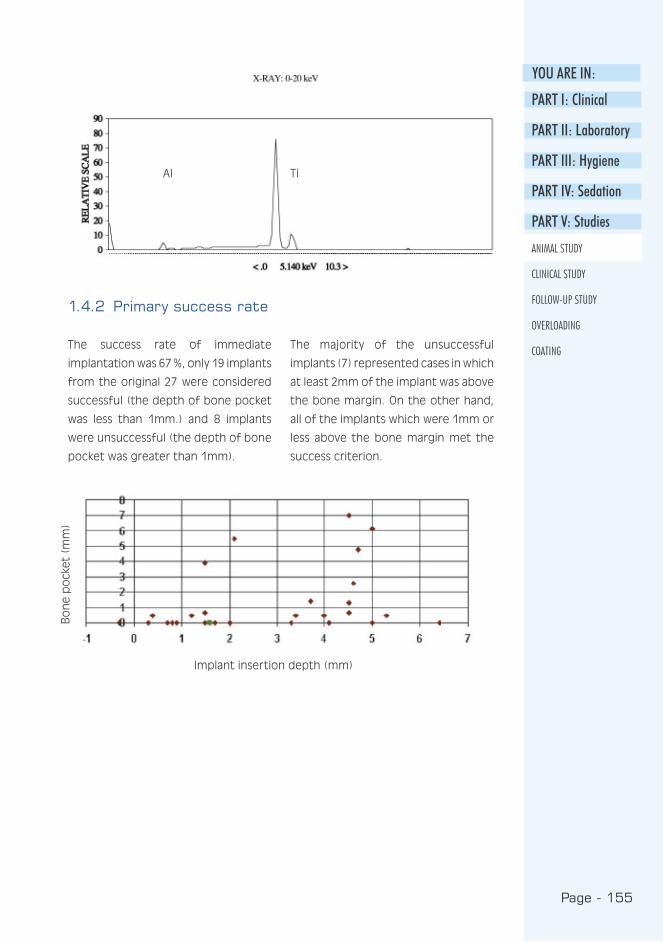
Page - 155
YOU ARE IN:
PART I: Clinical
PART II: Laboratory
PART III: Hygiene
PART IV: Sedation
PART V: Studies
ANIMAL STUDY
CLINICAL STUDY
FOLLOW-UP STUDY
OVERLOADING
COATINGThe success rate of immediate
implantation was 67 %, only 19 implants
from the original 27 were considered
successful (the depth of bone pocket
was less than 1mm.) and 8 implants
were unsuccessful (the depth of bone
pocket was greater than 1mm).
The majority of the unsuccessful
implants (7) represented cases in which
at least 2mm of the implant was above
the bone margin. On the other hand,
all of the implants which were 1mm or
less above the bone margin met the
success criterion.
1.4.2 Primary success rate
Implant insertion depth (mm)
Bo
ne
po
cket
(m
m)
AI Ti

Page - 156
Implant no. Contact with solid Fibrotic tissue bone (% of area) (% of area)
Implant 1 60.6 % 39.4 %
Implant 2 52.9 % 47.1 %
Implant 3 67.0 % 33.0 %
Implant 4 68.2 % 31.8 %
Implant 5 84.6 % 15.4 %
Implant 6 93.5 % 6.5 %
Implant 7 77.5 % 22.5 %
Implant 8 77.8 % 22.2 %
Implant 9 57.9 % 42.1 %
Implant 10 45.2 % 54.8 %
Implant 11 15.2 % 84.8 %
Implant 12 78.4 % 21.6 %
Implant 13 16.9 % 83.1 %
Implant 14 100 % 0 %
Implant 15 74.1 % 25.9 %
Mean 64.7 % 35.3 %
In histological evaluation a close
contact between compact bone
and the surface of the titanium
implant can easily be detected.
The light microscope evaluation
shows that the majority (65 %) of
the implant surface is in contact
with bone. A minority of the
surface is covered with epithelium
or connective tissue.
1.4.3 Microscopic evaluation of osteointegration
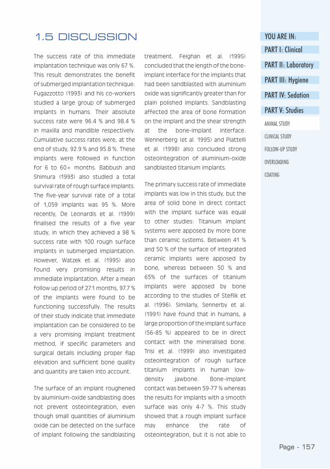
Page - 157
YOU ARE IN:
PART I: Clinical
PART II: Laboratory
PART III: Hygiene
PART IV: Sedation
PART V: Studies
ANIMAL STUDY
CLINICAL STUDY
FOLLOW-UP STUDY
OVERLOADING
COATING
1.5 DISCUSSION
treatment. Feighan et al. (1995)
concluded that the length of the bone-
implant interface for the implants that
had been sandblasted with aluminium
oxide was significantly greater than for
plain polished implants. Sandblasting
affected the area of bone formation
on the implant and the shear strength
at the bone-implant interface.
Wennerberg (et al. 1995) and Piattelli
et al. (1998) also concluded strong
osteointegration of aluminium-oxide
sandblasted titanium implants.
The primary success rate of immediate
implants was low in this study, but the
area of solid bone in direct contact
with the implant surface was equal
to other studies: Titanium implant
systems were apposed by more bone
than ceramic systems. Between 41 %
and 50 % of the surface of integrated
ceramic implants were apposed by
bone, whereas between 50 % and
65% of the surfaces of titanium
implants were apposed by bone
according to the studies of Steflik et
al. (1996). Similarly, Sennerby et al.
(1991) have found that in humans, a
large proportion of the implant surface
(56-85 %) appeared to be in direct
contact with the mineralised bone.
Trisi et al. (1999) also investigated
osteointegration of rough surface
titanium implants in human low-
density jawbone. Bone-implant
contact was between 59-77 % whereas
the results for implants with a smooth
surface was only 4-7 %. This study
showed that a rough implant surface
may enhance the rate of
osteointegration, but it is not able to
The success rate of this immediate
implantation technique was only 67 %.
This result demonstrates the benefit
of submerged implantation technique.
Fugazzotto (1993) and his co-workers
studied a large group of submerged
implants in humans. Their absolute
success rate were 96.4 % and 98.4 %
in maxilla and mandible respectively.
Cumulative success rates were, at the
end of study, 92.9 % and 95.8 %. These
implants were followed in function
for 6 to 60+ months. Babbush and
Shimura (1993) also studied a total
survival rate of rough surface implants.
The five-year survival rate of a total
of 1,059 implants was 95 %. More
recently, De Leonardis et al. (1999)
finalised the results of a five year
study, in which they achieved a 98 %
success rate with 100 rough surface
implants in submerged implantation.
However, Watzek et al. (1995) also
found very promising results in
immediate implantation. After a mean
follow up period of 27.1 months, 97.7 %
of the implants were found to be
functioning successfully. The results
of their study indicate that immediate
implantation can be considered to be
a very promising implant treatment
method, if specific parameters and
surgical details including proper flap
elevation and sufficient bone quality
and quantity are taken into account.
The surface of an implant roughened
by aluminium-oxide sandblasting does
not prevent osteointegration, even
though small quantities of aluminium
oxide can be detected on the surface
of implant following the sandblasting
Page - 158
significantly change the bone density.
A problem arises when attempting to
compare these results because the
direction of cutting the specimens is
not standardised i.e. sagittal cutting
shows mainly spongious bone and
frontal cutting compact bone.
1.5.1 Conclusions
The pure titanium which was abraded
by aluminium oxide sandblasting shows
a rough surface containing minor
aluminium remnants. This surface
demonstrates normal osteointegration
properties in beagle dogs but only in
cases with optimal insertion depth.
Our results are in harmony with clinical
experiences in the cases with
insufficient bone quality in which
- similarly - the optimal position
of implant and marginal bone were
not reached. The clinical success in
implantation depends mainly on the
optimal position of the implant and
the quality of the bone.
1.5.2 Acknowledgements
The authors want to thank the
Professors R-P. Happonen and A.
Yliurpo of the School of Dentistry at
the University of Turku for their help in
producing the histological preparates.
Page - 159
YOU ARE IN:
PART I: Clinical
PART II: Laboratory
PART III: Hygiene
PART IV: Sedation
PART V: Studies
ANIMAL STUDY
CLINICAL STUDY
FOLLOW-UP STUDY
OVERLOADING
COATING
REFERENCES
Babbush C, Shimura M : Five-year
statistical and clinical observations
with the IMZ two-stage
osteointegrated implant system. Int
J Oral Maxillofac Implants 1993 : 8 :
245-53.
De Leonardis D, Garg A, Pecora G :
Osseointegration of rough acid-
etched titanium implants: 5- year
follow-up of 100 minimatic-implants.
Int J Oral Maxillofac Implants 1999 :
14 : 384-91.
Feighan J, Goldberg V, Davy D, Parr
J, Stevenson S : The influence of
surface-blasting on the incorporation
of titanium-alloy implants in a rabbit
intramedullary model. J Bone Joint
Surg Am 1995 : 77 : 1380-95.
Fugazzotto P, Gulbransen H, Wheeler
S, Lindsay J : The use of IMZ
osteointegrated implants in partially
and completely edentulous patients:
success and failure rates of 2,023
implant cylinder up to 60+ months in
function. Int J Oral Maxillofac Implants
1993 : 8 : 617-21.
Piattelli A, Manzon L, Scarano A,
Paolantonio M, Piattelli M : Histologic
and histomorphometric analysis of
the bone response to machined and
sandblasted titanium implants: an
experimental study in rabbits. Int J
Oral Maxillofac Implants 1998 : 13 :
805-10.
Sennerby L, Ericson L, Thomsen P,
Lekholm U, Astrand P : Structure
of the bone-titanium interface in
retrieved clinical oral implants. Clin
Oral Implants Res 1991 : 2 : 103-11.
Steflik D, Lake F, Sisk A, Parr G,
Hanes P, Davis H, Adams B, Yavari J :
A comparative investigation in dogs:
2-year morphometric results of the
dental implant-bone interface. Int J
Maxillofac Implants 1996 : 11 : 15-25.
Trisi P, Rao W, Rebaudi A : A
histometric comparison of smooth
and rough titanium implants in
human low-density jawbone. Int J
Oral Maxillofac Implants 1999 : 14 :
689-98.
Watzek G, Haider R, Mensdorff-Pouilly
N, Haas R : Immediate and delayed
implantation for complete restoration
of the jaw following extraction of all
residual teeth: a retrospective study
comparing different types of serial
immediate implantation. Int J Oral
Maxillofac Implants 1995 : 10 : 561-7.
Wennerberg A, Albrektsson T,
Andersson B, Krol J : A
histomorphometric and removal
torque study of screw-shaped
titanium implants with three different
surface topographies. Clin Oral
Implants Res 1995 : 6 : 24-30.

Page - 160
Page - 161
YOU ARE IN:
PART I: Clinical
PART II: Laboratory
PART III: Hygiene
PART IV: Sedation
PART V: Studies
ANIMAL STUDY
CLINICAL STUDY
FOLLOW-UP STUDY
OVERLOADING
COATING
The OSFIX Dental Implant System - A Three-year Follow-up Study
Luotio K., DDS, PhD1,2 , Ryhänen J., DDS 1 , Kotilainen R., DDS, PhD, Prof.1,
Petrelius U., DDS1, Hanhela M., MSc 2
1 University of Kuopio, Institute of Oral Surgery, Kuopio, Finland
2 Osfix International Ltd, P.O. Box 14, Fin-47201 Elimäki, Finland
2.1 Abstract
Osfix implants are pure grade 2 titanium implants, the surfaces of which have
been mechanically roughened by sand blasting with aluminium oxide. The
integration property of the surface processing has been previously studied with
animal tests and histology. The aim of the Osfix clinical study was to verify
the success rate of the Osfix system. A total of 59 patients were operated on
and the number of implants inserted was 210. After a 3 month healing period,
impressions for the bar structures were taken and the mesiostructure bars
fabricated. These bars were then connected to an over-denture.
The follow-up results are available for 57 patients (203 implants). At the time of
the secondary operation, all of the implants were stabile. At the 3 year follow-up
inspection, no implants were lost. The success rate was 100 % for the implants
followed for 3 years. Patients were radiographically evaluated annually and the
mean marginal bone loss was 0.59mm (SD 0.42) after 1 year, 0.47mm (SD 0.42)
after 2 years and 0.58mm (SD 0.50) after 3 years. After the first year’s initial
marginal bone loss, no increase in bony pocket depth was detected. No clear
relationship between age, gender or number of implants inserted was noted.
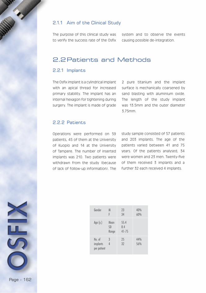
Page - 162
2.1.1 Aim of the Clinical Study
The Osfix implant is a cylindrical implant
with an apical thread for increased
primary stability. The implant has an
internal hexagon for tightening during
surgery. The implant is made of grade
2.2 Patients and Methods
2.2.1 Implants
2 pure titanium and the implant
surface is mechanically coarsened by
sand blasting with aluminium oxide.
The length of the study implant
was 13.5mm and the outer diameter
3.75mm.
2.2.2 Patients
Operations were performed on 59
patients, 45 of them at the University
of Kuopio and 14 at the University
of Tampere. The number of inserted
implants was 210. Two patients were
withdrawn from the study (because
of lack of follow-up information). The
study sample consisted of 57 patients
and 203 implants. The age of the
patients varied between 41 and 75
years. Of the patients analysed, 34
were women and 23 men. Twenty-five
of them received 3 implants and a
further 32 each received 4 implants.
The purpose of this clinical study was
to verify the success rate of the Osfix
system and to observe the events
causing possible de-integration.
Gender M 23 40% F 34 60%
Age (y.) Mean 55.4 SD 8.4 Range 41-75
No. of 3 25 44%implants 4 32 56%per patient
Page - 163
YOU ARE IN:
PART I: Clinical
PART II: Laboratory
PART III: Hygiene
PART IV: Sedation
PART V: Studies
ANIMAL STUDY
CLINICAL STUDY
FOLLOW-UP STUDY
OVERLOADING
COATING
2.2.3 Surgery
The implant site was exposed by a
large mucoperiosteal flap. A horizontal
incision was made on the crest of
the ridge, extending distally to the
mental foramens. A vertical releasing
incision in the median line was
sometimes required to achieve better
visibility of the field of surgery. The
mucoperiosteal flap was then raised
and the position of the mental
foramens identified and accessory
local anaesthetics injected into them.
Palpation of the undercuts with the aid
of a periodontal probe or elevator was
performed in order to avoid critical
areas in the lingual area during surgery.
The alveolar crest was smoothed with
a large round drill and the implant
sites marked with a small round drill.
The implant bed was prepared with a
standard drilling set cooled by external
irrigation with cold saline to a diameter
of 3.7mm and depth of 15mm. The
Osfix system allows free angulation,
but requires 5-15 degrees angulation
between holes.
The implants that would come into
contact with the bone were removed
from sterile ampoules and inserted
directly into the implant site to avoid
contamination with foreign material.
Four implants were used in the cases
of no or moderate resorption and
three implants in the cases of severe
resorption of the jaw bone (figures on
next page). The implants were initially
tapped into the holes with a mallet
and thereafter screwed and tightened
with a ratchet. The upper edge of
the implant was placed 0.5-1.0mm
below the upper bone margin. Before
wound closure, a primary cover screw
was screwed onto the implant. The
cover screw, which is 1.5mm in height,
remains 0.5-1.0mm above the level
of the bone. An antibiotic steroid
ointment (Terra-Cortril-P, Pfizer,
Brussels, Belgium) was applied to
the cover screw. Finally, the wound
was sutured with interrupted and
continuing sutures.
2.2.4 Prosthetic procedures
After primary surgery, a healing period
of 3 months is required before second
stage surgery. During this period, new
dentures for both the upper and lower
jaws were fabricated. Impressions were
taken with a facebow and the dentures
constructed according to the principle
that the canines should be parallel
with a line between the condyles of
the jawbone.
Impressions for the bar retention
structure were taken at this secondary
operation. The positions of the cover
screws were identified with a probe
and exposed with a scalpel. The
cover screws were unscrewed and
the impression posts inserted. The
impression was taken with a newly
fabricated lower jaw denture, which
had been relieved to make space
for the impression material. The
impression material was a vinyl
polyxane (Express, 3 M Dental
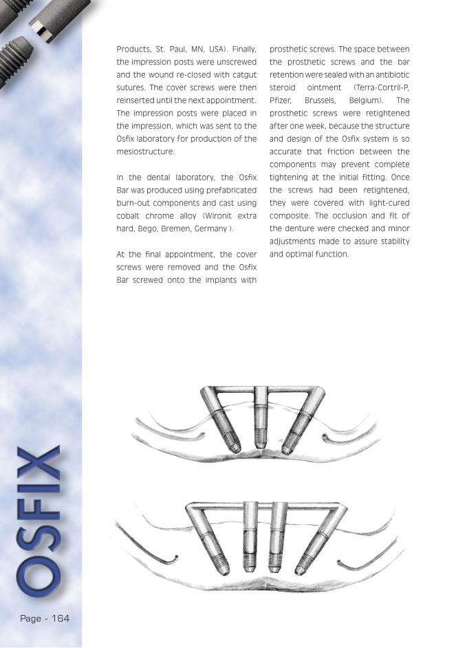
Page - 164
Products, St. Paul, MN, USA). Finally,
the impression posts were unscrewed
and the wound re-closed with catgut
sutures. The cover screws were then
reinserted until the next appointment.
The impression posts were placed in
the impression, which was sent to the
Osfix laboratory for production of the
mesiostructure.
In the dental laboratory, the Osfix
Bar was produced using prefabricated
burn-out components and cast using
cobalt chrome alloy (Wironit extra
hard, Bego, Bremen, Germany ).
At the final appointment, the cover
screws were removed and the Osfix
Bar screwed onto the implants with
prosthetic screws. The space between
the prosthetic screws and the bar
retention were sealed with an antibiotic
steroid ointment (Terra-Cortril-P,
Pfizer, Brussels, Belgium). The
prosthetic screws were retightened
after one week, because the structure
and design of the Osfix system is so
accurate that friction between the
components may prevent complete
tightening at the initial fitting. Once
the screws had been retightened,
they were covered with light-cured
composite. The occlusion and fit of
the denture were checked and minor
adjustments made to assure stability
and optimal function.
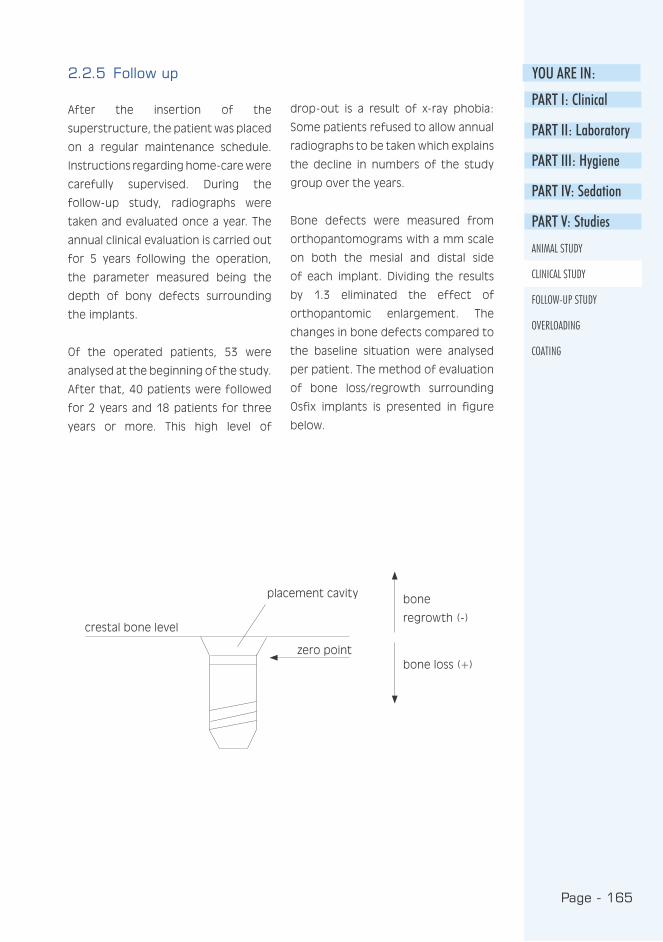
Page - 165
YOU ARE IN:
PART I: Clinical
PART II: Laboratory
PART III: Hygiene
PART IV: Sedation
PART V: Studies
ANIMAL STUDY
CLINICAL STUDY
FOLLOW-UP STUDY
OVERLOADING
COATING
2.2.5 Follow up
After the insertion of the
superstructure, the patient was placed
on a regular maintenance schedule.
Instructions regarding home-care were
carefully supervised. During the
follow-up study, radiographs were
taken and evaluated once a year. The
annual clinical evaluation is carried out
for 5 years following the operation,
the parameter measured being the
depth of bony defects surrounding
the implants.
Of the operated patients, 53 were
analysed at the beginning of the study.
After that, 40 patients were followed
for 2 years and 18 patients for three
years or more. This high level of
drop-out is a result of x-ray phobia:
Some patients refused to allow annual
radiographs to be taken which explains
the decline in numbers of the study
group over the years.
Bone defects were measured from
orthopantomograms with a mm scale
on both the mesial and distal side
of each implant. Dividing the results
by 1.3 eliminated the effect of
orthopantomic enlargement. The
changes in bone defects compared to
the baseline situation were analysed
per patient. The method of evaluation
of bone loss/regrowth surrounding
Osfix implants is presented in figure
below.
placement cavity
zero point
crestal bone level
bone
regrowth (-)
bone loss (+)

Page - 166
Of the 203 implants inserted, 143 were
analysed during the 2-year and 62
during the 3-year follow-up periods.
After 3 years, no implants had been
lost. The 3-year success rate of Osfix
implants was 100 %. The mean marginal
bone loss per patient was 0.58 mm
(SD=0.5) after 3 years evaluation
Mean bone defect (mm) per patient.
0 year 1 year 2 years 3 years
No. of patients 57 45 40 18
Mean 0 0.59 0.47 0.58
Median 0 0.58 0.50 0.72
SD 0.42 0.42 0.50
Min -0.10 -0.26 -0.26
Max 2.12 1.54 1.73
0.06 *
0.43 *
2.2.6 Statistics
The bone defects were measured
on the mesial and distal side of
each implant. This implied that at
each follow-up visit there were 6-8
measurements to be taken for each
patient. This information was
summarised by calculating two annual
summary statistics for each patient:
the mean bone defect and the
maximum bone defect. The changes
in bone defects from the baseline
were calculated. A Wilcoxon Signed
Rank test was used to compare the
results between different time points.
The analysis of variance (ANOVA) was
used to study the effects of gender,
age and number of implants 2 years
after implantation. SPSS (Version 10.0)
was used for the statistical analyses.
P-values less than 0.05 were considered
statistically significant.
2.3 Results
2.3.1 Success rate
p-value
* Wilcoxon Signed Rank Test

Page - 167
YOU ARE IN:
PART I: Clinical
PART II: Laboratory
PART III: Hygiene
PART IV: Sedation
PART V: Studies
ANIMAL STUDY
CLINICAL STUDY
FOLLOW-UP STUDY
OVERLOADING
COATING
Distribution of bone defects after 2 years (40 patients/143 implants).
50
40
30
20
10
0-6 -2 -1 0 1 2 3 5
period. Maximum bone defects are
shown in table above and bone defect
distribution after 2 years follow-up is
presented in figure below.
The Maximum bone defect (mm) per patient.
0 year 1 year 2 years 3 years
No. of patients 57 45 40 18
Mean 0 1.66 1.56 1.88
Median 0 1.54 1.54 1.54
SD 0.63 0.88 1.03
Min 0.77 0.00 0.77
Max 3.85 4.62 4.62
0.83 *
0.48 *
Bone loss
%
p-value
* Wilcoxon Signed Rank Test
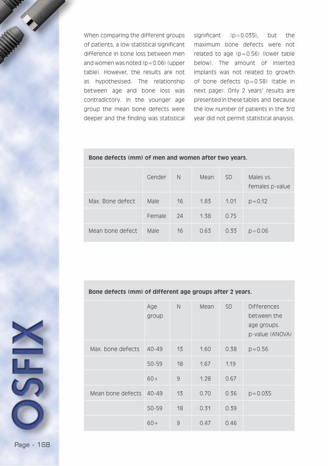
Page - 168
Bone defects (mm) of men and women after two years.
Gender N Mean SD Males vs.
females p-value
Max. Bone defect Male 16 1.83 1.01 p=0.12
Female 24 1.38 0.75
Mean bone defect Male 16 0.63 0.33 p=0.06
Bone defects (mm) of different age groups after 2 years.
Age N Mean SD Differences
group between the
age groups.
p- value (ANOVA)
Max. bone defects 40-49 13 1.60 0.38 p=0.56
50-59 18 1.67 1.19
60+ 9 1.28 0.67
Mean bone defects 40-49 13 0.70 0.36 p=0.035
50-59 18 0.31 0.39
60+ 9 0.47 0.46
When comparing the different groups
of patients, a low statistical significant
difference in bone loss between men
and women was noted (p=0.06) (upper
table). However, the results are not
as hypothesised. The relationship
between age and bone loss was
contradictory. In the younger age
group the mean bone defects were
deeper and the finding was statistical
significant (p=0.035), but the
maximum bone defects were not
related to age (p=0.56) (lower table
below). The amount of inserted
implants was not related to growth
of bone defects (p=0.58) (table in
next page). Only 2 years’ results are
presented in these tables and because
the low number of patients in the 3rd
year did not permit statistical analysis.
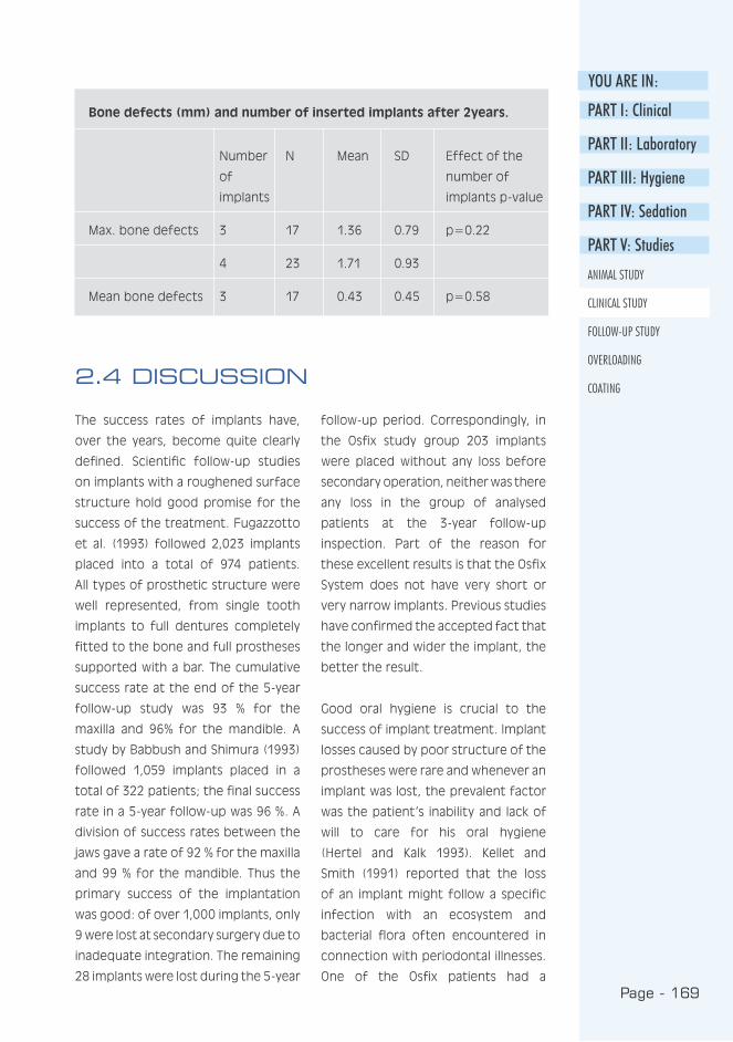
Page - 169
YOU ARE IN:
PART I: Clinical
PART II: Laboratory
PART III: Hygiene
PART IV: Sedation
PART V: Studies
ANIMAL STUDY
CLINICAL STUDY
FOLLOW-UP STUDY
OVERLOADING
COATING2.4 DISCUSSION
The success rates of implants have,
over the years, become quite clearly
defined. Scientific follow-up studies
on implants with a roughened surface
structure hold good promise for the
success of the treatment. Fugazzotto
et al. (1993) followed 2,023 implants
placed into a total of 974 patients.
All types of prosthetic structure were
well represented, from single tooth
implants to full dentures completely
fitted to the bone and full prostheses
supported with a bar. The cumulative
success rate at the end of the 5-year
follow-up study was 93 % for the
maxilla and 96% for the mandible. A
study by Babbush and Shimura (1993)
followed 1,059 implants placed in a
total of 322 patients; the final success
rate in a 5-year follow-up was 96 %. A
division of success rates between the
jaws gave a rate of 92 % for the maxilla
and 99 % for the mandible. Thus the
primary success of the implantation
was good: of over 1,000 implants, only
9 were lost at secondary surgery due to
inadequate integration. The remaining
28 implants were lost during the 5-year
follow-up period. Correspondingly, in
the Osfix study group 203 implants
were placed without any loss before
secondary operation, neither was there
any loss in the group of analysed
patients at the 3-year follow-up
inspection. Part of the reason for
these excellent results is that the Osfix
System does not have very short or
very narrow implants. Previous studies
have confirmed the accepted fact that
the longer and wider the implant, the
better the result.
Good oral hygiene is crucial to the
success of implant treatment. Implant
losses caused by poor structure of the
prostheses were rare and whenever an
implant was lost, the prevalent factor
was the patient’s inability and lack of
will to care for his oral hygiene
(Hertel and Kalk 1993). Kellet and
Smith (1991) reported that the loss
of an implant might follow a specific
infection with an ecosystem and
bacterial flora often encountered in
connection with periodontal illnesses.
One of the Osfix patients had a
Bone defects (mm) and number of inserted implants after 2years.
Number N Mean SD Effect of the
of number of
implants implants p-value
Max. bone defects 3 17 1.36 0.79 p=0.22
4 23 1.71 0.93
Mean bone defects 3 17 0.43 0.45 p=0.58
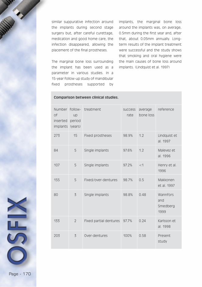
Page - 170
Comparison between clinical studies.
Number follow- treatment success average reference
of up rate bone loss
inserted period
implants (years)
273 15 Fixed prostheses 98.9% 1.2 Lindquist et
al. 1997
84 5 Single implants 97.6% 1.2 Malevez et
al. 1996
107 5 Single implants 97.2% <1 Henry et al.
1996
155 5 Fixed/over-dentures 98.7% 0.5 Makkonen
et al. 1997
80 3 Single implants 98.8% 0.48 Wannfors
and
Smedberg
1999
133 2 Fixed partial dentures 97.7% 0.24 Karlsson et
al. 1998
203 3 Over-dentures 100% 0.58 Present
study
similar suppurative infection around
the implants during second stage
surgery but, after careful curettage,
medication and good home care, the
infection disappeared, allowing the
placement of the final prostheses.
The marginal bone loss surrounding
the implant has been used as a
parameter in various studies. In a
15-year follow-up study of mandibular
fixed prostheses supported by
implants, the marginal bone loss
around the implants was, on average,
0.5mm during the first year and, after
that, about 0.05mm annually. Long-
term results of the implant treatment
were successful and the study shows
that smoking and oral hygiene were
the main causes of bone loss around
implants. (Lindquist et al. 1997)
Page - 171
YOU ARE IN:
PART I: Clinical
PART II: Laboratory
PART III: Hygiene
PART IV: Sedation
PART V: Studies
ANIMAL STUDY
CLINICAL STUDY
FOLLOW-UP STUDY
OVERLOADING
COATING
Karlsson et al. (1998) has studied
maxillary and mandibular fixed partial
dentures supported by implants for
2 years. He has evaluated the
difference between two different
implant surfaces: machined and TiO-
blasted. The amount of installed
implants was 133. When the results
of both implants and jaws were
combined, the marginal bone loss
was 0.24mm (SD=0.69) after 2 years
follow-up. No statistically significant
difference was found between studied
implant types. Wannfors, with his
co-workers (1999), has studied single
implant restorations. Eighty implants
were inserted and only 1 implant was
lost during the 3-year follow-up period.
The average marginal bone loss was
0.48mm during the evaluation period.
In the Osfix clinical study the mean
marginal bone loss was 0.58mm
(SD=0.5) after a 3-year evaluation
period. This result is in agreement with
the other above-mentioned studies
(Table on previous page). There was no
clear significant difference in marginal
bone loss related to gender, and
men’s more frequent use of tobacco
may explain this minimal difference.
Nor could the difference between
age groups be clearly related to the
growth of bone defects after 2 years
follow-up. However, no differences
were found related to the number of
inserted implants.
This study confirms earlier studies,
which describe implant treatment as
a safe method with few surgical
complications and minimal marginal
bone loss. The complications caused
by poor structure of the prostheses
were rare, but good oral hygiene is
considered to be a very important
factor in the success of implant
treatment.
2.5 CONCLUSIONS
The complication level was very low
when inserting Osfix implants. The
mean bone loss per patient was
0.58mm during the 3-year observation
period. No implants were lost; hence
the success rate of the Osfix implant is
100 % after 3 years follow-up in 1999.
2.6 ACKNOWLEDGEMENT
We wish to extend our gratitude to
Mrs. Tuija Poussa for her assistance
with the statistical analysis.
Page - 172
REFERENCES
Babbush C, Shimura M : Five year
statistical and clinical observations
with the IMZ two stage
osteointegrated implant system. Int
J Oral Maxillofac Implants 1993: 3 :
245-53.
Fugazzotto P , Gulbransen H , Wheeler
S , Lindsay J A : The use of IMZ
osseointegrated implants in partially
and completely edentulous patients:
success and failure rates of 2023
implant cylinders up to 60+ months
in function. Int J Oral Maxillofac
Implants 1993: 6: 617-21.
Henry P, Laney W, Jemt T, Harris D,
Krogh P, Polizzi G, Zarb G, Herrmann I :
Osseointegrated implants for single-
tooth replacement; a prospective
5-year multicenter study. Int J Oral
Maxillofac Implants 1996 : 11 : 450-4.
Hertel R, Kalk W : Influence of the
dimensions of implant superstructure
on peri implant bone loss. Int J
Prosthodont 1993 : 1 : 18-24.
Karlsson U, Gotfredsen K, Olsson
C : A 2-year report on maxillary
and mandibular fixed partial dentures
supported by Astra Tech dental
implants. A comparison of 2 implants
with different surface textures. Clin
Oral Implants Res 1998 : 9 : 235-42.
Kellet M, Smith G : The epithelial
interface with osseointegrated
implants. Dent Health (London) 1991 :
3 : 6-9.
Lindquist L , Carlsson G, Jemt T : A
prospective 15-year follow-up study
of mandibular fixed prostheses
supported by osseointegrated
implants. Clinical results and marginal
bone loss. Clin Oral Res 1997 :8 : 342.
Makkonen T, Holmberg S, Niemi L,
Olsson C, Tammisalo T, Peltola J : A
5-year prospective clinical study of
Astra Tech dental implants supporting
fixed bridges or overdentures in
the edentulous mandible. Clin Oral
Implants Res 1997 : 8 : 469-75.
Malevez C, Hermans M, Daelemans P
: Marginal bone levels at Brånemark
system implants used for single tooth
restoration. The influence of implant
design and anatomical region. Clin
Oral Implants Res 1996 : 7 : 162.
Wannfors K, Smedberg J : A
prospective clinical evaluation of
different single-tooth restoration
designs on osseointegrated implants.
A 3-year follow-up of Brånemark
implants. Clin Oral Implants Res 1999 :
10 : 453-8.
Page - 173
YOU ARE IN:
FOLLOW-UP STUDY:
THE EFFECTS OF OSFIX IMPLANTATION ON THE QUALITY OF LIFE, AND
PERCEPTIONS ON HOME CARE
Luotio K., DDS, PhD1, Turunen J. 2, Hanhela M., M.Sc.1
1 Osfix International Ltd Oy, P.O. Box 14, FIN-47201 Elimäki
2 Pohjois-Savo Polytechnic, Kuopio, Finland
3.1 ABSTRACT
The purpose of the study was to determine the effects of implantation on the
quality of life and to obtain information on the oral home care of patients. The
subject group were patients who had received implants and a Dolder-type bar
construction for a mandibular prosthesis, and who had a traditional removable
prosthesis on the maxilla. The questionnaire was mailed to 58 people. Forty-nine
questionnaires were returned, representing a reply rate of 84 %.
Implantation did have an effect on the patients’ quality of life. The patients
considered their present mandibular and maxillary prostheses significantly
better than those they had used previously. They were particularly satisfied
with the prostheses on the mandible. Those patients who replied considered
the present prosthesis on the mandible better than those they had used
previously(p<0.0001). The prosthesis on the maxilla was also regarded as
considerably better than those they had used previously(p<0.0001). The main
benefit resulting from implantation was the ease of laughing and mastication.
The oral home care of implant patients had worked out well. The patients felt
confident with the various cleaning methods used in their oral care, and they
considered themselves able to clean both the bar and the prostheses well. The
most common cleaning aids were the toothbrush and interdental brush, which
were used on average twice a day.
PART I: Clinical
PART II: Laboratory
PART III: Hygiene
PART IV: Sedation
PART V: Studies
ANIMAL STUDY
CLINICAL STUDY
FOLLOW-UP STUDY
OVERLOADING
COATING

Page - 174
Traditional dentures are often
considered cumbersome and
unpleasant; some people never get
used to them. Implant treatments
offer solutions for many problems
caused by the use of prostheses
(Salonen 1996; Hujanen 1996). Users
do not feel comfortable as they need
to think about how to keep the
prosthesis in place. Everyday functions
such as eating, laughing and speaking
may cause a feeling of insecurity
(Seddon and Smith). The poor stability
of the prosthesis may also cause
sore pressure cuts on the mucosa
(Laine and Lindqvist 1996). Implant
treatments offer a solution for many
of the problems caused by the use
of prostheses (DuCoin 1996; Myers
Kracher and Schmeling Smith 1998).
Long-term implant treatment requires,
in addition to successful ossification
and a well planned and executed
prosthesis structure, satisfactory oral
hygiene (Talonpoika and Uusitalo 1997).
Oral home care is an important part
of implant treatment. To maintain
a healthy tissue, careful removal of
plaque around the implant is essential.
Plaque causes gingivitis and bleeding
in the same way as it does in the tissue
around a natural tooth. To maintain
oral health, the care of an implant
patient includes cleaning at home and
regular appointments at a dental clinic
(Torres 1995). To secure the success
of home care, it is important that
the patient is confident with the oral
cleansing methods (Babbush 1991;
Spindler 1999). Because efficient oral
cleansing has a direct effect on the
success of the implant treatment, the
role of the medical staff in patient
guidance is enhanced (Seddon and
Smith). When choosing the cleansing
aids, the main emphasis should be
simplicity in use and the minimum
number of implements, as an excessive
number of articles may be considered
cumbersome (Myers Kracher and
Schmeling Smith 1998).
3.2 INTRODUCTION
3.2.1 Aim of study
The purpose of the study was to
determine the effects of implantation
on the quality of life, and to obtain
information on the oral home care of
patients.
Page - 175
YOU ARE IN:
Anonymous questionnaires were sent
to 58 patients who had received
implants and a Dolder-type bar
construction for a mandibular
prosthesis, and who had a traditional
prosthesis on the maxilla. Forty-nine
questionnaires were returned,
representing a reply rate of 84 %. No
reply was disqualified. Of the answers
received, 32 were from women and
17 from men. The age of the subjects
ranged between 40-82 years.
The questionnaire consisted of 25
questions, of which 3 were open
questions, 3 opinion-based questions
to be measured with a linear meter
(VAS: Visual Analogy Scale), and the
remaining part structured questions
(Statements with Likert scale, “yes-no”
questions and multi-choice questions).
There was also a question on the
subject’s sex and year of birth.
This report concentrates on analysing
the questions concerning the quality
of life and oral hygiene at home,
two of the questions metering VAS-
change, and three being multi-choice
questions.
The patients’ experiences of
prostheses and their ability to care
for the them was measured with VAS
technique (length of line 10 cm).
The results are given as medians and
ranges. A Wilcoxon signed ranks test
was used to compare the variables,
and Spearman rank correlations were
calculated to study the associations
between these variables.
The box plot figures were drawn to
describe the distributions of variables.
The box represents the interquartile
range and the whiskers indicate the
highest and lowest values, excluding
outliers. A line across the box indicates
the median. SPSS (Version 9.0)
statistical program was used for
statistical analyses.
PART I: Clinical
PART II: Laboratory
PART III: Hygiene
PART IV: Sedation
PART V: Studies
ANIMAL STUDY
CLINICAL STUDY
FOLLOW-UP STUDY
OVERLOADING
COATING
3.3 PATIENTS AND METHODS
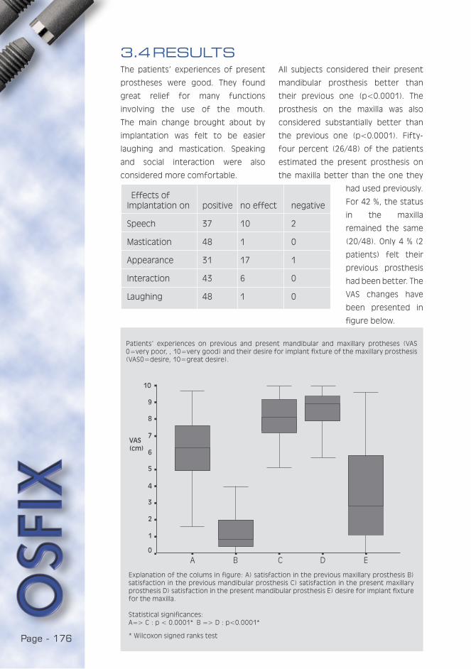
Page - 176
Effects ofImplantation on positive no effect negative
Speech 37 10 2
Mastication 48 1 0
Appearance 31 17 1
Interaction 43 6 0
Laughing 48 1 0
3.4 RESULTSThe patients’ experiences of present
prostheses were good. They found
great relief for many functions
involving the use of the mouth.
The main change brought about by
implantation was felt to be easier
laughing and mastication. Speaking
and social interaction were also
considered more comfortable.
All subjects considered their present
mandibular prosthesis better than
their previous one (p<0.0001). The
prosthesis on the maxilla was also
considered substantially better than
the previous one (p<0.0001). Fifty-
four percent (26/48) of the patients
estimated the present prosthesis on
the maxilla better than the one they
had used previously.
For 42 %, the status
in the maxilla
remained the same
(20/48). Only 4 % (2
patients) felt their
previous prosthesis
had been better. The
VAS changes have
been presented in
figure below.
A B C D E
Patients’ experiences on previous and present mandibular and maxillary protheses (VAS 0=very poor, , 10=very good) and their desire for implant fixture of the maxillary prosthesis (VAS0=desire, 10=great desire).
Explanation of the colums in figure: A) satisfaction in the previous maxillary prosthesis B) satisfaction in the previous mandibular prosthesis C) satisfaction in the present maxillary prosthesis D) satisfaction in the present mandibular prosthesis E) desire for implant fixture for the maxilla.
Statistical significances:A=> C : p < 0.0001* B => D : p<0.0001*
* Wilcoxon signed ranks test
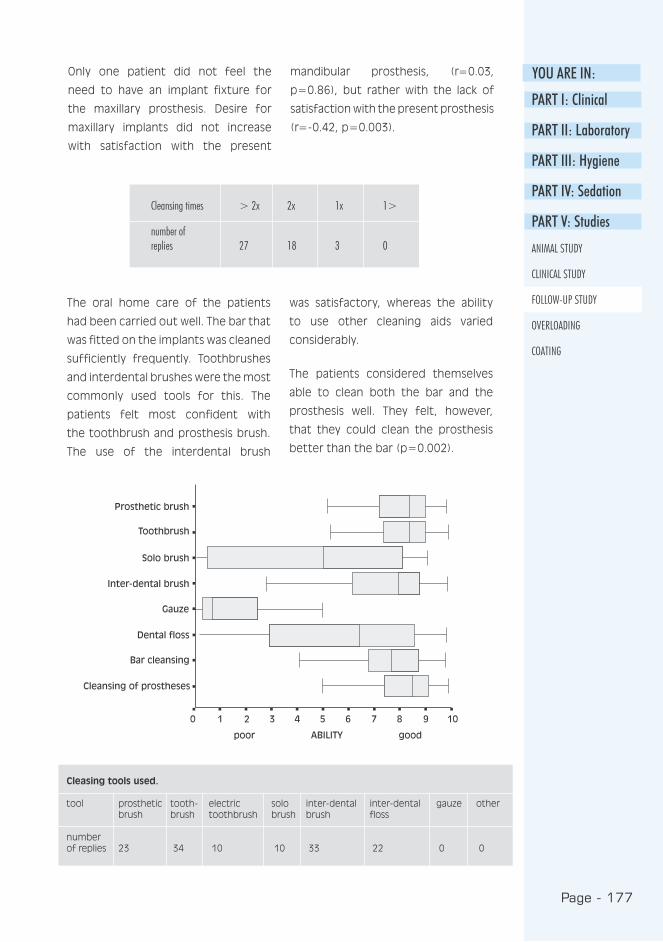
Page - 177
YOU ARE IN:
Cleansing times > 2x 2x 1x 1>
number ofreplies 27 18 3 0
Cleasing tools used.
tool prosthetic tooth- electric solo inter-dental inter-dental gauze other brush brush toothbrush brush brush floss
number of replies 23 34 10 10 33 22 0 0
PART I: Clinical
PART II: Laboratory
PART III: Hygiene
PART IV: Sedation
PART V: Studies
ANIMAL STUDY
CLINICAL STUDY
FOLLOW-UP STUDY
OVERLOADING
COATING
Only one patient did not feel the
need to have an implant fixture for
the maxillary prosthesis. Desire for
maxillary implants did not increase
with satisfaction with the present
mandibular prosthesis, (r=0.03,
p=0.86), but rather with the lack of
satisfaction with the present prosthesis
(r=-0.42, p=0.003).
The oral home care of the patients
had been carried out well. The bar that
was fitted on the implants was cleaned
sufficiently frequently. Toothbrushes
and interdental brushes were the most
commonly used tools for this. The
patients felt most confident with
the toothbrush and prosthesis brush.
The use of the interdental brush
was satisfactory, whereas the ability
to use other cleaning aids varied
considerably.
The patients considered themselves
able to clean both the bar and the
prosthesis well. They felt, however,
that they could clean the prosthesis
better than the bar (p=0.002).

Page - 178
Implantation had a positive effect
on the patients’ quality of life. They
felt their present prostheses were
much better than their previous ones.
Particular improvement was felt with
the mandibular prosthesis. Some need
was also felt to fix the maxillary
prosthesis on implants. The main
changes felt after the implantation
were easier laughing and mastication.
The patients’ experiences on the
improvement of oral functions as
a result of implant treatment were
similar to those stated in previous
studies (Ducoin 1996, CibIrka et al.
(1997), Myers Kracher and Schmeling
Smith 1998). In addition to the changes
mentioned above, the patients felt
their appearance had improved, their
speech had become easier and their
interaction with other people had
become more pleasant. In addition to
functional benefits, the requirements
of the patients for factors increasing
social interaction are considered
important (Myers Kracher and
Schmeling Smith 1998).
3.5 DISCUSSION
It is essential that the implant
prosthesis patient is meticulous about
their oral home care, both in quality
and frequency. Daily oral hygiene
includes the cleansing and examination
of the bar structure, prostheses and
mucosa. Special attention must be paid
to the cleansing of the bar structure.
As the mandibular prostheses may be
unfastened, visibility of the implant-
fixed bar is improved and its cleansing
is facilitated (Lawrence 1991). Oral
home care was carried out well among
the subjects. They cleaned the bar
sufficiently frequently and with the
right methods, which is essential for
the success of the implant treatment.
In addition to this, it is important that
they considered oral hygiene to be
important and were interested in their
personal oral hygiene. On the whole,
the patients felt confident with the
new cleansing methods.
3.5.1 CONCLUSIONS
1. Implantation did have an effect on
the improvement of the patients’
quality of life, and they felt their
present mandibular and maxillary
prostheses were significantly better
than those they had used
previously.
2. The patients felt confident about
oral home care.
Page - 179
YOU ARE IN:
PART I: Clinical
PART II: Laboratory
PART III: Hygiene
PART IV: Sedation
PART V: Studies
ANIMAL STUDY
CLINICAL STUDY
FOLLOW-UP STUDY
OVERLOADING
COATING
REFERENCES
Babbush C : Dental Implants :
principles and practice. W. B. USA:
Saunders Company 1991.
Cibirka R, Razzoog M, Lang B : Critical
evaluation of patient responses to
dental implant therapy. J Prosth Dent
1997 : 78 : 574-581.
DuCoin J : Dental implant hygiene and
maintenance. Home and professional
care. J Oral Impl 1996 : 22 : 72-75.
Hujanen E : Prosthetics of the
edentulous mouth (in Finnish). In:
Meurman J, Murtomaa H, Le Bell
Y, Autti H, Luukkanen M (editors) :
Therapia odontologia. Forssa, Finland:
Academica Kustannus 1996.
Laine L, Lindqvist C : Preproteettinen
kirurgia ja implantologia (Pre-
prosthetic surgery and implantology).
In: Meurman J, Murtomaa H, LeBell
Y, Autti H, Luukkanen M. (editors) :
Therapia odontologia. Forssa, Finland:
Academica Kustannus 1996.
Lawrence L : Oral hygiene for dental
implant patients. Texas Dental J 1991 :
108 : 21-23.
Myers Kracher C, Schmeling Smith W :
Oral health maintenance of dental
implants: A Literature Review. The
Dental Assistant 1998 : 2-14.
Salonen S : Implanttiprotetiikka
(Implant prosthetics). Meurman J,
Murtomaa H, Le Bell, Y, Autti H.,
Luukkanen M. (editors) Therapia
odontologia. Forssa: Academica
kustannus 1996.
Seddon I, Smith K : The hygienist s
role in an implant practice. Dental
Health 1998 : 37 : 5-7.
Spindler J. 1998. How should dental
implants be maintained? http:/
/ourwold.compuserve.com/
homepages/perio-horizons/
pg3.HTM.20.1.1999.
Talonpoika J, Uusalo E : Maintenance
care of the implant patient (in
Finnish)). The Finnish Dentists’ Journal
1997 : 7 : 327-375.
Torres E : Modern dental assisting.
W.B. USA: Saunders Company 1995.

Page - 180
Page - 181
YOU ARE IN:
PART I: Clinical
PART II: Laboratory
PART III: Hygiene
PART IV: Sedation
PART V: Studies
ANIMAL STUDY
CLINICAL STUDY
FOLLOW-UP STUDY
OVERLOADING
COATING
The Behaviour of OSFIX Implant Components in Overload
Situations
Luotio K., DDS, PhD 1, Jatkola S. Dent Techn2, Halonen T. Dent Techn2, Lappi T.
Dent Techn1, Hanhela M., MSc1
1 Osfix International Ltd P.O. Box 14, FIN 47201 Elimaki, Finland
2 The Helsinki Polytechnic, Finland
4.1 ABSTRACT
The purpose of the study was to determine the effects of overloading on
BiOsfix single tooth implants and the prosthetic screws joining the crown and the
implant. The implants and the screws were submitted to fatigue and fracture
resistance tests with appropriately designed equipment. The screw material was
both grade 2 and grade 4 titanium and the implants were made of grade 2
titanium. Observations were made on the differences between the different
grades on the basis of the tests.
In an overload situation, the screws acted as fuses, breaking at the safety groove
and protecting the implant from damage. Even in the fatigue test, the screws
resisted hundreds of thousands of 200 N cycles. The number of cycles needed
to break the screws was 150,000 ->850,000, by which time 6 out of 11 screws
tested had broken (range 150,000 - 300,000).
These fracture resistance tests demonstrated that the fracture resistance of
grade 4 titanium was greater; the fracture resistance of grade 2 alloy was
between 239.48-261.94 N and that of grade 4 alloy 289.39-302.53 N. The
distortion of grade 4 titanium before fracture was, however, less than that of
grade 2 titanium. This makes grade 2 titanium safer in the event of concussion.
Under the forces exerted by chewing, the screw is adequately strong. Normally,
the bending moments on the implant during chewing remain below 200 N.
In emergency situations the implants bent, whereas the fatigue test did not
inflict any changes.
On the basis of the tests it can be stated that in an overload situation the implant
and the prosthetic screw will yield at the planned point, and that the grade 2
titanium used as implant and screw material is sufficiently strong and flexible,
even in emergency situations.
Page - 182
One of the possible complications of
implant treatment is the occurrence
of an implant fracture. Biomechanical
overload and metal fatigue are the
most common causes of fractured
implants. (Piattelli et al. 1998) Clinical
studies indicate that loosening or
fracture of implant prostheses occurs
in 5 to 45 % of cases during the first
year. The nature of the loosening of
prosthetic components is complicated,
since it involves cycling fatigue, oral
fluids and varied chewing patterns and
loads. (Sakaguchi & Borgersen 1995).
Implant fractures can cause significant
problems. Some researchers suggest
that these problems could be related
to prosthetic and functional stresses
associated with progressive bone loss.
(Zarb & Schmitt 1990 and Rangert &
Forsmalm 1993). The fact remains that
chewing and maximum bite forces
differ widely between individuals.
Richter (1998) investigated the in
vivo horizontal bending moments on
implants.
An implant in the molar position that
is connected to a mesial tooth by
a prosthesis is loaded by vertical
and horizontal forces during any oral
function. Vertical loads are transmitted
directly to the bone around the
implant. The most important result
of his study was that chewing loads
in the transverse direction caused
the highest bending moments in the
implant and the surrounding bone.
These were 4 to 5 times greater
than the bending moments in a
mesiodistal direction. Horizontal forces
are transmitted via a lever arm,
creating bending moments.
In his study, a specially designed
load cell was placed directly in the
implant permitting the measurements
of bending moments. The transverse
loads during chewing resulted in the
highest bending moments of 170
Nmm max. and the highest stress in
the bone was 6.2 MPa at the crest on
the buccal side. The mesial bending
is not critical (52 Nmm mean max.
moment).
Richter (1995) also studied in vivo
vertical forces on implants during
oral functions. Implants in the molar
position that were fixed to a premolar
with a prosthesis withstood maximum
vertical forces of 60 to 120 N during
chewing. Single molars and premolars
carried maximum vertical forces of
120 to 150 N. The high stress areas
are located at the implant’s neck
(Siegele 1989). Implant fractures may
be a result of implant design and
manufacturing, non-passive fit of the
framework or biomechanical overload
(Balshi et al. 1996).
4.2 INTRODUCTION

Page - 183
YOU ARE IN:
PART I: Clinical
PART II: Laboratory
PART III: Hygiene
PART IV: Sedation
PART V: Studies
ANIMAL STUDY
CLINICAL STUDY
FOLLOW-UP STUDY
OVERLOADING
COATING
4.3 AIMS OF THE STUDY
Transformations in the implant caused by overloading
a) under stress (fatigue test)
b) in an emergency situation
(fracture resistance test)
For the prosthetic screw:
a) the number of chewing cycles
required for a fracture
b) the force required for a fracture
c) the fracture point
crown
implant
prosthetic screw
The aim of the study was to determine
the effects of overloading on BiOsfix
single tooth implants and the
prosthetic screws (joining the crown
and the implant). In exact terms the
following was defined:
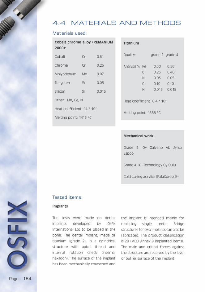
Page - 184
Tested items:
Implants
The tests were made on dental
implants developed by Osfix
International Ltd to be placed in the
bone. The dental implant, made of
titanium (grade 2), is a cylindrical
structure with apical thread and
internal rotation check (internal
hexagon). The surface of the implant
has been mechanically coarsened and
4.4 MATERIALS AND METHODS
Materials used:
Cobalt chrome alloy (REMANIUM
2000):
Cobalt Co 0.61
Chrome Cr 0.25
Molybdenum Mo 0.07
Tungsten W 0.05
Silicon Si 0.015
Other: Mn, Ce, N
Heat coefficient: 14 * 10-1
Melting point: 1415 ºC
Titanium
Quality: grade 2 grade 4
Analysis % Fe 0.30 0.50
0 0.25 0.40
N 0.03 0.05
C 0.10 0.10
H 0.015 0.015
Heat coefficient: 8.4 * 10-1
Melting point: 1688 ºC
Mechanical work:
Grade 2: Oy Galvano Ab Jyrso
Espoo
Grade 4: Ki -Technology Oy Oulu
Cold curing acrylic: (PalaXpress®)
the implant is intended mainly for
replacing single teeth. Bridge
structures for two implants can also be
fabricated. The product classification
is 2B (MDD Annex 9 implanted items).
The main and critical forces against
the structure are received by the level
or buffer surface of the implant.

Page - 185
YOU ARE IN:Prosthetic screws
The purpose of the screw is to fasten
the prosthetic structure to the implant
and to stabilise the structure, which
consists of various components, in
this case of cobalt chrome alloy, to
PART I: Clinical
PART II: Laboratory
PART III: Hygiene
PART IV: Sedation
PART V: Studies
ANIMAL STUDY
CLINICAL STUDY
FOLLOW-UP STUDY
OVERLOADING
COATING
The crown
For test purposes, a superstructure
in the shape of a tooth was made of
cobalt chrome by lost wax casting.
safety groove
The waxing was done on a burn-out
developed by Osfix Ltd. The same
superstructure was used in all tests.
make it as rigid as possible. To control
fractures, a safety groove has been
made on the screws immediately above
the threads.
Fatigue test
Equipment
The implants were tested on fatigue
equipment in which the mandible
denture was made from cobalt
chrome. The maxilla was made of
acrylic base with one implant. The
cobalt chrome structure was fitted
on the implant with grade 2 titanium
prosthetic screws.
The fatigue test equipment was the
Pro-Test (J. H. Engineering Ky), which
has been developed for such tests.
The equipment enables the regulation
of concussion frequency and the
pressure between the jaws of the
implement. The concussion frequency
was regulated based by concussions/
second, and changes in pressure were
made through atmospheric pressure
and a valve. The equipment could
also be programmed with the desired
number of concussions, which was
then completed unless the power was
switched off.

Page - 186
Testing
The jaws were set for light chewing
and they were burdened as follows:
five implants with rounded edges were
strained 1,000,000 times/structure.
Repetitions were made twice a second
by pressing the parts together
occlusally at 200 N. The fatigue was
continued until a prosthetic screw
broke. The test was then paused and,
after changing the screw, the test was
continued in the same way until the
1,000,000 limit.
When the one million concussion limit
was reached, the acrylic was removed
from around the implant. For the next
implant, retentions were made in the
hole thus created. A new implant was
fitted in place of the previous one
with a silicon index, and new acrylic
was poured around the implant. The
acrylic was hardened as above.
Analysis
The fracture surfaces appearing in the
prosthetic screws were observed with
a scanning electron microscope (SEM),
Philips XL-20, with an EDS analysator
(manufacturer EDAX).
Fracture resistance test
Equipment
The test equipment was Zwick Z250
stress device/meter. A suitable implant
holder as well as a presser piece
was manufactured for the fracture
resistance test. The superstructure
of the implant was always the same
cobalt chrome structure that was also
used in the fatigue test.
Testing
The test was made on the same
implants as in the fatigue test, as
they remained unbroken. To fasten the
cobalt chrome structure, two different
types of prosthetic screws were used:
grade 2 and grade 4.
The implant holder was tightened to
enable the presser piece to strike the
structure from above, 10mm from the
widest part beginning at the implant
socket. The presser piece struck
directly on the titanium prosthetic
screw that emerged from a hole in
the cobalt chrome structure. The test
had to be made with the palatinal
side of the cobalt chrome structure
uppermost, as the facial surface was
too round.
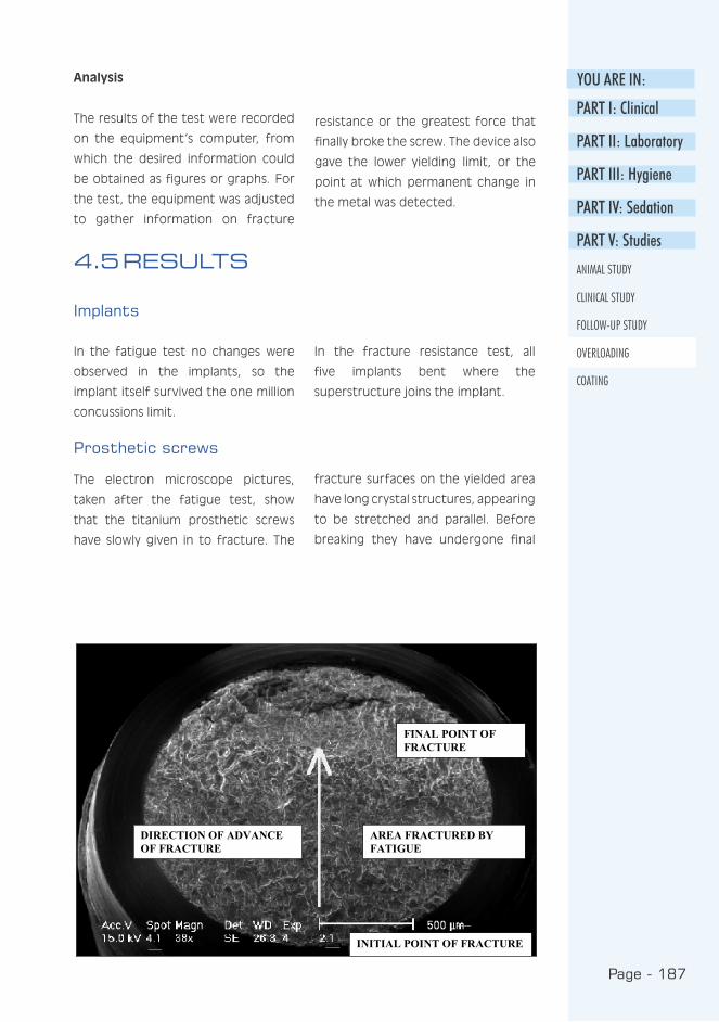
Page - 187
YOU ARE IN:Analysis
The results of the test were recorded
on the equipment’s computer, from
which the desired information could
be obtained as figures or graphs. For
the test, the equipment was adjusted
to gather information on fracture
resistance or the greatest force that
finally broke the screw. The device also
gave the lower yielding limit, or the
point at which permanent change in
the metal was detected.
PART I: Clinical
PART II: Laboratory
PART III: Hygiene
PART IV: Sedation
PART V: Studies
ANIMAL STUDY
CLINICAL STUDY
FOLLOW-UP STUDY
OVERLOADING
COATING
4.5 RESULTS
Implants
In the fatigue test no changes were
observed in the implants, so the
implant itself survived the one million
concussions limit.
In the fracture resistance test, all
five implants bent where the
superstructure joins the implant.
Prosthetic screws
The electron microscope pictures,
taken after the fatigue test, show
that the titanium prosthetic screws
have slowly given in to fracture. The
fracture surfaces on the yielded area
have long crystal structures, appearing
to be stretched and parallel. Before
breaking they have undergone final
Figure 3. Electron microscope picture of the fracture surface of the screw after the fatigue test.
INITIAL POINT OF FRACTURE
AREA FRACTURED BYFATIGUE
DIRECTION OF ADVANCEOF FRACTURE
FINAL POINT OFFRACTURE

Page - 188
fracture which is rough and small
structured. The number of cycles
(upper table below) needed to break
the prosthetic screws was 150,000
-> 850,000, at which point 6 out
of 11 tested prosthetic screws had
broken (range 150,000 - 300,000,
mean 263,333).
The fracture resistance curves were
similar in structure for both grade
2 and grade 4 titanium prosthetic
screws (figures next page). The
fracture resistance for grade 2 alloy
was between 239.48-261.94 N and
for grade 4 alloy 289.39-302.53 N
respectively (lower table below). The
results show that grade 4 alloy is ca.
20 % stronger. It was also observed
in the graphic curves that grade 4
could better resist bending. Grade 2
alloy screws bent 3.40-3.93 mm before
breaking. The bend in grade 4 alloy
was 2.44-2.69 mm.
Breaking point: All broken prosthetic
screws broke along the safety groove
both in the fatigue test and in the
fracture resistance test.
Results of the fatigue test.
broken screws number of cycles
1 150,000
2 300,000
3 280,000
4 290,000
5 280,000
6 280,000
mean 263,333
Results of the fracture resistance test.
grade no. of screw breaking force (N) bending (mm)
2 1 261.64 3.93
2 2 239.48 3.40
2 3 253.52 3.74
mean 251.55 3.69
4 1 289.39 2.69
4 2 302.53 2.44
4 3 301.76 2.55
mean 297.89 2.56

Page - 189
YOU ARE IN:
PART I: Clinical
PART II: Laboratory
PART III: Hygiene
PART IV: Sedation
PART V: Studies
ANIMAL STUDY
CLINICAL STUDY
FOLLOW-UP STUDY
OVERLOADING
COATING
Figure 4. The fracture resistance curves a) grade 2 titanium
b) grade 4 titanium
The fracture resistance curves
Figure 4. The fracture resistance curves a) grade 2 titanium
b) grade 4 titanium
a) grade 2 titanium
b) grade 4 titanium
Page - 190
4.6 DISCUSSION
The purpose of the study was to
determine the effects of overloading
on BiOsfix single tooth implants and
the prosthetic screws joining the
crown and the implant. On the basis
of the tests, the durability of BiOsfix
implant material during chewing was
evaluated, as well as the safety of
the implant in a possible concussion
situation.
In an overload situation, the screws
acted as “fuses”, in that they gave
way and thus protected the implant
from damage. Even in the fatigue
test, during which the screws were
subjected to a force of 200 N, the
screw endured hundreds of thousands
of cycles. In an overload situation
the screw broke at the correct point
or along the safety groove, which
facilitates the repair of the implant
structure. A comparison of the fracture
resistance graphs between grade 2 and
grade 4 titanium qualities shows that
grade 2 titanium has lower fracture
resistance, but bends more before
breaking than grade 4. This makes
it safer in a concussion situation
(violence, accident), as it would be less
likely that the superstructure of the
implant would be entirely removed
when the screw bends.
When we observe the durability of
the screw when subjected to chewing
loads, we can state the screw is
sufficiently strong. In the test the
screws and implants were burdened
with 200 N for hundreds of thousands
of cycles. The bending moments on
the implant during chewing usually
remain at a maximum of 170 N (Richter
1998). It has to be noted, however,
that chewing forces differ widely
between individuals. Mericske-Stern et
al. (1995) made a comparison between
maximum chewing forces of implant
patients. The chewing forces on an
implant-supported, fixed prosthesis
varied between 200-300 N. The force
is, however, shared by several
implants.
In an emergency situation, the implant
showed distortion between the
superstructure and the implant. This
damage could, nevertheless, in most
cases be repaired with burn-out
components. On the other hand, the
fatigue test created no changes in the
implant.
4.7 CONCLUSIONS
On the basis of the tests it can
be stated that the prosthetic screw
will yield at the planned point in an
overload situation, and that the grade
2 titanium used in both implants and
prosthetic screws is sufficiently strong
and elastic in an emergency situation.
Page - 191
YOU ARE IN:
PART I: Clinical
PART II: Laboratory
PART III: Hygiene
PART IV: Sedation
PART V: Studies
ANIMAL STUDY
CLINICAL STUDY
FOLLOW-UP STUDY
OVERLOADING
COATING
REFERENCES
Balshi T, Hernandez R, Pryszlak M,
Rangert B : A comparative study of
one implant versus two replacing a
single molar. Int J Oral Maxillofac
Implants 1996: 11: 372-378.
Mericske-Stern R, Assal P, Mericske E,
Burgin W : Occlusal force and oral
tactile sensibility measured in partially
edentulous patients with ITI implants.
Int J Oral Maxillofac Implants 1995 :
10 : 345-53.
Piattelli A, Scarano A, Piattelli M,
Vaia E, Matarasso S : Hollow implants
retrieved for fracture: a light and
scanning electron microscope
analysis of 4 cases. J Periodontol
1998 : 69 : 185-9.
Rangert B, Forsmalm G : Strenght
characteristics of CP titanium.
Nobelpharma News 1993 : 7 : 4-5.
Richter E : In vivo vertical forces on
implants. Int J Oral Maxillofac Implants
1995 : 10 : 99-108.
Richter E : In vivo horizontal bending
moments on implants. Int J Oral
Maxillofac Implants 1998 : 13 :
232-44.
Sakaguchi R, Borgersen S : Nonlinear
contact analysis of preload in dental
implant screws. Int J Oral Maxillofac
Implants 1995 : 10 : 295-302.
Siegele D : Numerische
Untersuchungen zur Optimierung der
durch Zahnimplantate bedigten
Beanspruchung des Kieferknochens.
Thesis. Fraunhofer-Institut für
Werkstoffmechanik. Freiburg,
Germany: W 8/89, 1989.
Zarb G, Schmitt A : The longitudinal
clinical effectiveness of
osseointegrated dental implants : The
Toronto study. Part I: Surgical results.
J Prosthet Dent 1990 : 63: 451-457.

Page - 192
Page - 193
YOU ARE IN:
COATING:
THIN FILMS ON THE SURFACE OF COBALT CHROME
K. Luotio, DDS, PhD 1, 2, T. Stenberg PhD,3, P. Vuoristo, PhD 3, T. Mäntylä Prof.
PhD 3 and R.M.Kotilainen, Prof. DDS, PhD 2
1 Osfix Oy / Ltd, Box 14, FIN-47201 Elimäki, Finland
2 University of Kuopio, Institute of Oral Surgery
3 Tampere University of Technology, Institute of Materials Science,
5.1 ABSTRACT
Three different coatings for cast CoCr -alloy dental implant frameworks were
studied. Coatings were approx. 1 mm thick TiN+Ti - and Ti+TiN -double layers
and Ti+DLC gradient structure film manufactured with PVD deposition methods.
The corrosion resistance of these films was studied with immersion tests,
electrochemical polarisation tests and by measuring the amount of dissolved
metal ions. The corrosive medium was a physiological saline solution. The
structures of the films were studied with a scanning electron microscope (SEM).
All the films studied provided good corrosion protection and the amount of
dissolved Co-ions was reduced by up to 90 % compared to the base material.
This reduction may have important clinical significance in cases of allergy to
the components of CoCr-alloy and in cases where there is a need to enhance
biocompatibility.
PART I: Clinical
PART II: Laboratory
PART III: Hygiene
PART IV: Sedation
PART V: Studies
ANIMAL STUDY
CLINICAL STUDY
FOLLOW-UP STUDY
OVERLOADING
COATING

Page - 194
Dental implant frameworks (i.e. mesio-
and super-structures) are
conventionally made of gold alloys.
However, mainly for economic reasons,
cobalt chrome alloy is an interesting
material for the same purpose. Cobalt
chrome alloy is commonly used in
prosthodontics and it is a well-known
material by both dentists and dental
technicians. One of the disadvantages
of cobalt chrome alloy is its hardness,
which makes the material difficult
to handle in a dental laboratory.
Possible allergic reactions to cobalt
chrome should also be considered,
even though they are extremely rare
(Moberg 1958, Stenberg 1982,
Kotilainen 1991). Nevertheless, all
structures must be designed to enable
the removal of cobalt chrome alloy
components from implant and dental
structures. According to the previously
mentioned studies, all cobalt chrome
alloy components may also dissolve in
oral conditions. Galvanic corrosion has
been claimed to cause loss of bone
around the implant (Adell et al. 1981,
Geis-Gerstorfer et al. 1989). The clinical
follow-up made on implant prostheses
does not, however, support this claim
(Hulterström et al. 1994, Luotio 1997)
but the loss of bone is at the same
level as with gold-based structures
(Alberektsson et al. 1986, Knotek
et al. 1992). To produce a coating
on cast CoCr-alloy seems to be a
more practical and economical method
to achieve more corrosion resistant
implant frameworks than producing
e.g. a titanium prosthesis. The casting
of titanium requires considerably more
complex technology including a
protective gas atmosphere.
5.2 INTRODUCTION
5.1.2 The aims of this study were:
1) to describe the surface of CoCr-alloy
after it was coated with common
biocompatible materials.
2) to investigate if it is possible to
decrease the solubility of cobalt
chrome components with thin film
technology.
3) to determine an adequate method
for coating dental implant
frameworks.
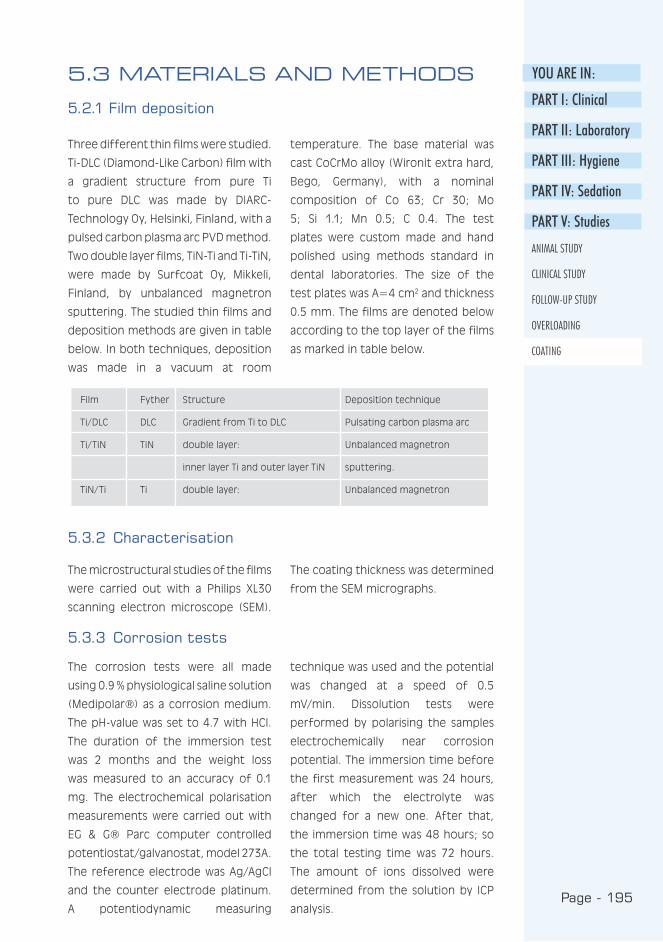
Page - 195
YOU ARE IN:
Three different thin films were studied.
Ti-DLC (Diamond-Like Carbon) film with
a gradient structure from pure Ti
to pure DLC was made by DIARC-
Technology Oy, Helsinki, Finland, with a
pulsed carbon plasma arc PVD method.
Two double layer films, TiN-Ti and Ti-TiN,
were made by Surfcoat Oy, Mikkeli,
Finland, by unbalanced magnetron
sputtering. The studied thin films and
deposition methods are given in table
below. In both techniques, deposition
was made in a vacuum at room
temperature. The base material was
cast CoCrMo alloy (Wironit extra hard,
Bego, Germany), with a nominal
composition of Co 63; Cr 30; Mo
5; Si 1.1; Mn 0.5; C 0.4. The test
plates were custom made and hand
polished using methods standard in
dental laboratories. The size of the
test plates was A=4 cm2 and thickness
0.5 mm. The films are denoted below
according to the top layer of the films
as marked in table below.
5.3 MATERIALS AND METHODS
5.2.1 Film deposition
5.3.2 Characterisation
The microstructural studies of the films
were carried out with a Philips XL30
scanning electron microscope (SEM).
The coating thickness was determined
from the SEM micrographs.
5.3.3 Corrosion tests
The corrosion tests were all made
using 0.9 % physiological saline solution
(Medipolar®) as a corrosion medium.
The pH-value was set to 4.7 with HCl.
The duration of the immersion test
was 2 months and the weight loss
was measured to an accuracy of 0.1
mg. The electrochemical polarisation
measurements were carried out with
EG & G® Parc computer controlled
potentiostat/galvanostat, model 273A.
The reference electrode was Ag/AgCl
and the counter electrode platinum.
A potentiodynamic measuring
technique was used and the potential
was changed at a speed of 0.5
mV/min. Dissolution tests were
performed by polarising the samples
electrochemically near corrosion
potential. The immersion time before
the first measurement was 24 hours,
after which the electrolyte was
changed for a new one. After that,
the immersion time was 48 hours; so
the total testing time was 72 hours.
The amount of ions dissolved were
determined from the solution by ICP
analysis.
Film Fyther Structure Deposition technique
Ti/DLC DLC Gradient from Ti to DLC Pulsating carbon plasma arc
Ti/TiN TiN double layer: Unbalanced magnetron
inner layer Ti and outer layer TiN sputtering.
TiN/Ti Ti double layer: Unbalanced magnetron
PART I: Clinical
PART II: Laboratory
PART III: Hygiene
PART IV: Sedation
PART V: Studies
ANIMAL STUDY
CLINICAL STUDY
FOLLOW-UP STUDY
OVERLOADING
COATING
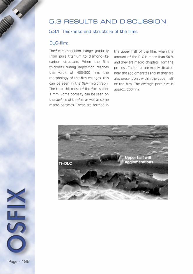
Page - 196
DLC-film:
The film composition changes gradually
from pure titanium to diamond-like
carbon structure. When the film
thickness during deposition reaches
the value of 400-500 nm, the
morphology of the film changes, this
can be seen in the SEM-micrograph.
The total thickness of the film is app.
1 mm. Some porosity can be seen on
the surface of the film as well as some
macro particles. These are formed in
the upper half of the film, when the
amount of the DLC is more than 50 %
and they are macro-droplets from the
process. The pores are mainly situated
near the agglomerates and so they are
also present only within the upper half
of the film. The average pore size is
approx. 200 nm.
5.3 RESULTS AND DISCUSSION
5.3.1 Thickness and structure of the films
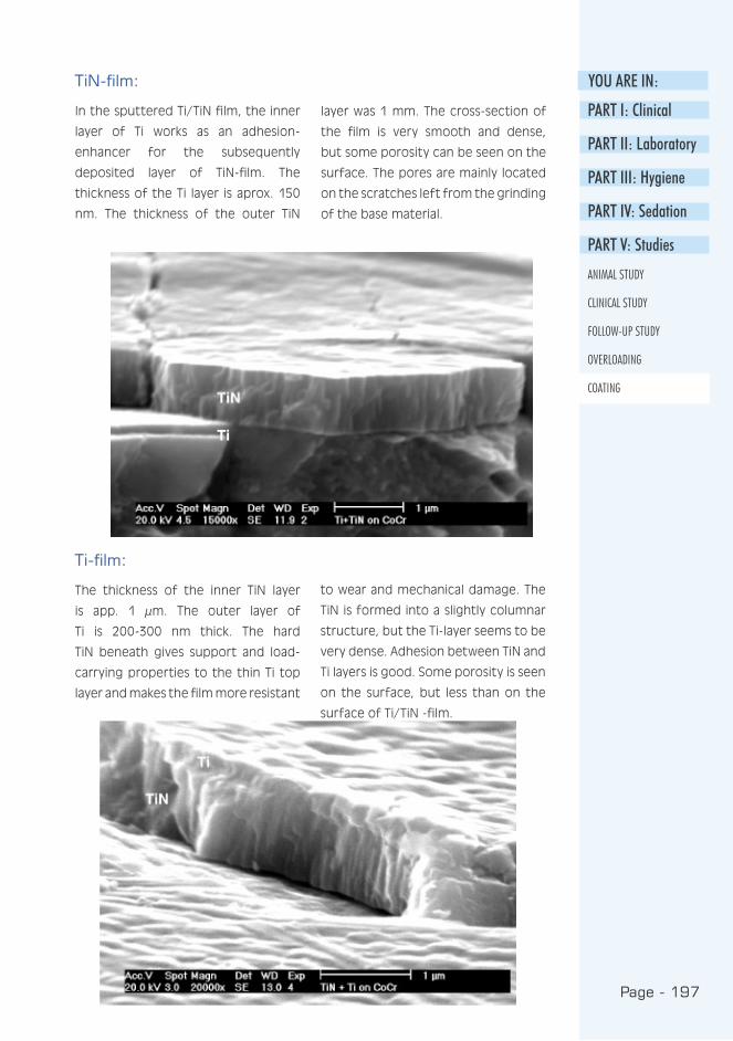
Page - 197
YOU ARE IN:
PART I: Clinical
PART II: Laboratory
PART III: Hygiene
PART IV: Sedation
PART V: Studies
ANIMAL STUDY
CLINICAL STUDY
FOLLOW-UP STUDY
OVERLOADING
COATING
TiN-film:
In the sputtered Ti/TiN film, the inner
layer of Ti works as an adhesion-
enhancer for the subsequently
deposited layer of TiN-film. The
thickness of the Ti layer is aprox. 150
nm. The thickness of the outer TiN
layer was 1 mm. The cross-section of
the film is very smooth and dense,
but some porosity can be seen on the
surface. The pores are mainly located
on the scratches left from the grinding
of the base material.
Ti-film:
The thickness of the inner TiN layer
is app. 1 µm. The outer layer of
Ti is 200-300 nm thick. The hard
TiN beneath gives support and load-
carrying properties to the thin Ti top
layer and makes the film more resistant
to wear and mechanical damage. The
TiN is formed into a slightly columnar
structure, but the Ti-layer seems to be
very dense. Adhesion between TiN and
Ti layers is good. Some porosity is seen
on the surface, but less than on the
surface of Ti/TiN -film.
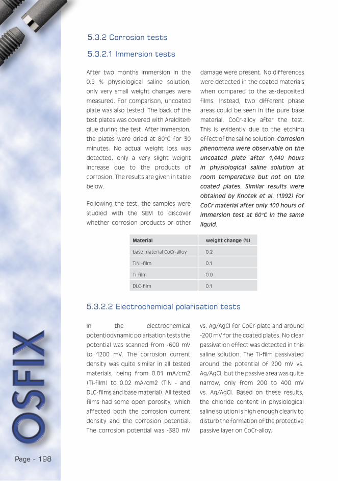
Page - 198
Material weight change (%)
base material CoCr-alloy 0.2
TiN -film 0.1
Ti-film 0.0
DLC-film 0.1
After two months immersion in the
0.9 % physiological saline solution,
only very small weight changes were
measured. For comparison, uncoated
plate was also tested. The back of the
test plates was covered with Araldite®
glue during the test. After immersion,
the plates were dried at 80°C for 30
minutes. No actual weight loss was
detected, only a very slight weight
increase due to the products of
corrosion. The results are given in table
below.
Following the test, the samples were
studied with the SEM to discover
whether corrosion products or other
damage were present. No differences
were detected in the coated materials
when compared to the as-deposited
films. Instead, two different phase
areas could be seen in the pure base
material, CoCr-alloy after the test.
This is evidently due to the etching
effect of the saline solution. Corrosion
phenomena were observable on the
uncoated plate after 1,440 hours
in physiological saline solution at
room temperature but not on the
coated plates. Similar results were
obtained by Knotek et al. (1992) for
CoCr material after only 100 hours of
immersion test at 60°C in the same
liquid.
5.3.2 Corrosion tests
5.3.2.1 Immersion tests
5.3.2.2 Electrochemical polarisation tests
In the electrochemical
potentiodynamic polarisation tests the
potential was scanned from -600 mV
to 1200 mV. The corrosion current
density was quite similar in all tested
materials, being from 0.01 mA/cm2
(Ti-film) to 0.02 mA/cm2 (TiN - and
DLC-films and base material). All tested
films had some open porosity, which
affected both the corrosion current
density and the corrosion potential.
The corrosion potential was -380 mV
vs. Ag/AgCl for CoCr-plate and around
-200 mV for the coated plates. No clear
passivation effect was detected in this
saline solution. The Ti-film passivated
around the potential of 200 mV vs.
Ag/AgCl, but the passive area was quite
narrow, only from 200 to 400 mV
vs. Ag/AgCl. Based on these results,
the chloride content in physiological
saline solution is high enough clearly to
disturb the formation of the protective
passive layer on CoCr-alloy.
Page - 199
YOU ARE IN:
CoCr Ti-film DLC-film TiN-film
metal ions, ppm Cr: 5.14 Cr: 0.24 Cr: 0.74 Cr: 1.61after 24 hours Co:8.7 Co: 1.31 Co: 2.2 Co:4.41
metal ions, ppm Cr:5.37 Cr: 1.12 Cr: 2.65 Cr: 4.6 after 72 hours Co:14.68 Co: 2.5 Co: 4.49 Co: 8.49
PART I: Clinical
PART II: Laboratory
PART III: Hygiene
PART IV: Sedation
PART V: Studies
ANIMAL STUDY
CLINICAL STUDY
FOLLOW-UP STUDY
OVERLOADING
COATING
In order to have more information
on the protective behaviour of the
coatings, the dissolved metal ions in
the corrosive media were measured.
Diluted into the liquid, the cobalt was
found to dissolve at much higher
rate (nearly 3 times faster) than the
chromium from the base material. No
other ions from the cast alloy were
detected. Some traces of dissolved Ti
ions were detected from the TiN film,
indicating some extent of dissolution
in the film. From the studied materials,
the Ti-film seemed to be the densest
and the most corrosion resistant, since
the smallest amounts of Co and Cr were
detected in the solution. When Ti-film
was used, the amount of dissolved Co
was reduced to 9 % of that detected
for uncoated CoCr-alloy. With DLC-film
the amount of Co was reduced to
30 % and with TiN-film to 60 % of the
uncoated alloy. The results are shown
in table below. These results reveal that
the sputtered Ti-film gives a higher
protection than the TiN-film prepared
by the same coating process.
5.4.2.3 Measurements of dissolved ions
5.4.3 Medical point of view
All the examined materials have been
accepted as highly biocompatible in
medical literature. Titanium has been
used as implant material for over 30
years and TiN coating is in common use
and produced for dental applications
by one Danish company (Gradjean
1995) at least. From a clinical point
of view, the surface hardness of
the exposed metallic framework is
important because calculus removal is
a procedure which is highly abrasive
and potentially damaging. Thus the
DLC is the most interesting material.
Moreover, it is in common use in
heart valve prosthesis (Elizondo et
al. 1996, Monties et al. 1997) and
under consideration for hip prosthesis
Nordsletten et al. (1996). The
biocompatibility of DLC is well
documented Kornu et al. (1996) using
both cell culture and animal tests.
In dental use, if not implanted, the
only theoretical channel for systemic
effects is the digestive canal. The
question is academic, not practical,
because large amounts of diamond
are swallowed for decades after every
dental operation as a result of the
wearing of diamond drills. Moreover,
diamond is carbon which has been
used as a medicine for centuries.
When coatings are used in dental
prostheses, we have to accept that
these frameworks are not serial
products, but custom made. Thus the
structures always contain areas which
are not perfectly polished and the
behaviour of the coating material in
such surfaces needs further study.
Page - 200
All the studied films were slightly
porous due to the coating processes.
Surface scratches were found to be
the preferred sites for pore formation.
The structure of the sputtered Ti-layer
seemed to be the densest of these
studied films whereas TiN tended to
form a slightly columnar structure.
The DLC film contained some small
agglomerates within the upper half of
the film.
All the coatings were able to reduce
the amount of dissolved ions from
the base material. The reduction of
dissolved Co-ions was from 40 to 90 %.
The lowest reduction was observed
in TiN coating which is in common
use for decreasing the corrosion of
surgical drills. This study showed that
the use of TiN may no longer be the
best material for the purpose, because
we now have better alternatives.
The other facts affecting the choice
between these films are hardness,
coverage of the coating if complex
shape frameworks are coated,
availability of the coating and cost.
Both Ti and DLC are promising coatings
to prevent CoCr ion release and the
hardness of the surface of DLC makes
it most interesting. The problem of
DLC is that the gradient process with
titanium is not in common use and the
commonly used process with tungsten
does not produce stabile coatings for
biocompatible use.
5.4.4 Conclusions
5.4.5 Acknowledgements
We would like to thank Professor Jouni
Tummavuori from the University of
Jyväskylä, Finland, for valuable help in
the chemical analyses. In addition we
are very grateful for the dedicated
handwork of Ms. Satu Luukkainen,
dental technician, in producing and
polishing the plates.

Page - 201
YOU ARE IN:
PART I: Clinical
PART II: Laboratory
PART III: Hygiene
PART IV: Sedation
PART V: Studies
ANIMAL STUDY
CLINICAL STUDY
FOLLOW-UP STUDY
OVERLOADING
COATING
REFERENCES
Adell R, Lekholm U, Rockler B,
Brånemark P : A 15-year study
of osseointegrated implants in the
treatment of the edentulous jaw. Int J
Oral Surg 1981 : 6: 387-416.
Albrektsson T, Zarb C, Worthington P,
Eriksson A : The long-term efficacy
of currently used dental implants:
A review and proposed criteria of
success. Int J Oral Maxillofac Implants
1986 : 1 : 11-25
Elizondo D, Boland E, Ambrus J, Kurk J
: Mechanical cardiac valve prostheses:
wear characteristics and magnitudes
in three bileaflet valves. J Heart Valve
Disease. 1996 : 5 :115-23.
Geis-Gerstorfer J, Weber H, Sauer
K-H : In vitro substance loss due to
galvanic corrosion in Ti implant/ Ni-Cr
supraconstruction systems. Int J Oral
Maxillofac Implants 1989: 4 :119-123
Grandjean F : Industrial coatings
revolutionise dental care. New Nordic
Technology 1995 : 3 : 5.
Hulterström M , Nilsson U : Cobalt-
Chromium as a framework material in
implant-supported fixed prosthesis: a
3-year Follow-up. Int J Oral Maxillofac
Implants 1994 : 4 : 449-454
Knotek O, Löffer K and Weitkamp K :
Surface and Coatings Technology
1992 : 54/55 : 536-540.
Kotilainen, R : Eine Analyse von 100
Problempatienten mit
Suprakonstructionen und
Schleimhautbeschwerden mit
Referenz zu methodischen Aspecten
in allergologischer Sicht. GOI
Jahrbuch, Quintessenz 1991: 237-241.
Kornu R, Maloney W, Kelly M, Smith R :
Osteoblast adhesion to orthopaedic
implant alloys: effects of cell
adhesion molecules and diamond-like
carbon coating. J Orthopaed Res.
1996 : 14 : 871-7.
Luotio K : IMZ- and Frialit-2 implants (in
Finnish) The Finnish Dentists’ Journal
1997 : 7: 356-362.
Moberg L. E : Long-term corrosion
studies in vitro of gold. cobalt-
chromium and nickel-chromium alloys
in contact. Acta Odontol Scand 1985 :
43 : 215-222.
Monties J, Dion I, Havlik P, Rouais F,
Trinkl J, and Baquey C : Cora rotary
pump for implantable left ventricular
assist device: biomaterial aspects.
Artificial Organs 1997 : 21 : 730-4.
Nordsletten L, Hogasen A, Konttinen
Y, Santavirta S, Aspenberg P, Aasen
A : Human monocyte stimulation by
particles of hydroxyapatite, silicon
carbide and diamond: in vitro studies
of new prosthesis coatings.
Biomaterials 1996 : 17 : 1521-7.
Stenberg T : Release of cobalt from
cobalt-chromium alloy construction in
oral cavity of man. Scand J Dent Res
1982 : 472-479.

Page - 202
Page - 203
KEYWORDS:
A Acrylated ....................23Agonists......................125Ambu ..........................130Analysator...................186Anesthesiological........143Angulating ..................49Angulation ..................75 ...81 ...163Anteriorically...............23Anterograde ...............128Antigenes ...................33Anxiolytes ...................128Anxiolytic ....................125..126Apatite........................17....33Apposed .....................157Aseptics ......................152
B Benzodiazepines.........117..121..122 123..124..125 127..129 .130 131..133..135 137..138 .139 141..143Biocompatibility .........193..199Biocompatible ............194 .199 .200Biomechanical ............82 ...182Buccal .........................63 ...182Buccally ......................79
C Chlorhexidine .............114Calcitonin....................33Cancellous ..................33Cannula.......................123..128..129 130..135..137 138..140 .142Cannulation ................53 ...123..129 130..135..140Cefalosporin ...............54Chlorhexidine .............114CoCr ............................19....193..198 199..200Condylar .....................93 ...95Condyles .....................69 ...163Corallic ........................17Correlations ................175Crestal ........................42 ...165Crista ..........................17....54 ...59
D Dentoalveolar .............35Desaturation...............137Desmethyldiazepam ...127Diazepines...................125Dihydrostreptomycin..152Discolouration ............113..114Disinfection ................87 ...89 ...91 93 ...95 ...97 99 ...100Dorsum.......................122..123Doxazepram................131
Dysmorphophobia......36
E Endodontal .................35Endosteal....................35Endothracheal ............130..143Ethylic .........................54Etilephrine ..................131
F Facebow .....................69 ...163Fb-Glu .........................38Felypressin..................54Fibrointegration .........34Flumazenil...................117..126..130 137..138 .139Formaline ...................152Fossa...........................122..123..138
G Galvanostat.................195Galvanous ...................16Gastroenterological ....126Gingiva ........................99 ...106 .107 108 .110..111 114Glycosaminoglycans....33
H Haematoma................123Haemostasis ...............54Handpiece...................50 ...53 ...54 68 ...73 ...75Handwash ...................52HCl ..............................195Histological .................15....32 ...153 156..158Hyperbaric ..................36 ...37Hypnotics....................127Hypoxic .......................37
I Iatrogenic ...................81Indometacin ...............54Interdental..................99 ...108 .110 111..114..173 177Interquartile ...............175Intraoral ......................39Intubation...................130..143Ischemy ......................142
J Junctional ...................35
K Keypoints ....................87 ...93 ...95 96 ...97 ...99
L Leucocytes .................38Lingually......................59 ...69Luer.............................129
M

Page - 204
Mandibular..................42 ...54 ...81 89 ...148 .151 152..170..171 172..173..175 176..177 .178Mentale.......................42Mesial..........................165..166 .182Mesiodistal..................182Mesiostructure ...........48 ...161..164Methacrylate ..............153Micrographs................195Microstructural ...........195Midazolam ..................54 ...117..121 126..127..128 129..131..136 139..140 .141 142Millary .........................41Mucoperiosteal...........163Mucosa .......................17....36 ...59 103..105 .106 107..108 .109 111..113..114 174..178Mucosal.......................35Myastenia ...................122
N Nalorphin....................130Neuroleptics ...............128
O Occlusal.......................18....24 ...39 47 ...48 ...49 74....87 ...92 93 ...97 ...98 99 ...191Occlusally ....................186Orthopantomograms .165Os................................54 ...121..141Osteoblasts .................33 ...34Osteoclasts .................33Osteogenic .................34Osteonectin................33Overdenture ...............16....24 ...48 87 ...89 ...91 92 ...93 ...95 97 ...99 ...161Oversedated ...............121..138Oximeter.....................39 ...52 ...53 133..134 .135 136Oximetry .....................117..131..133 134..135..140Oxyhaemoglobin ........133..134
P Palatinal ......................186Parathormone ............33Paravenous .................135..140Parentheral.................126Passivated...................198Periodontics ...............39Periodontitis ...............36Periosteal....................17
Periosteum.................33 ...54Phagocytic..................34Pharmacodynamics ....117..124..125Pharmacokinetic.........117..124..125Phenolic......................52Polyxane .....................163Potentiate ..................127Potentiodynamic ........195..198Potentiostat ...............195Premedication ............89 ...126..128 129..144Preparates ..................158Prilocaine....................54Procain .......................152Procallus .....................34Prosthodontic ............81 ...148Prosthodontics ...........9 .....194Pseudarthrosis............34Pseudoperiodontal.....34Psychogenic ...............119..141..143
R Radiologically..............16....152Radiolucence ..............32Rebase ........................95Regreasing..................61 ...73Regrowth....................165Resedation..................138Resorbable..................57Resorbed ....................23 ...44 ...48Resorption..................34 ...48 ...163Retightened................164Retightening...............73
S Sagittal .......................158Salbutamol .................131Sedationist..................130..143Simeditine...................128Spongious...................33 ...41 ...48 158Sprue ..........................91 ...93 ...96Spruing .......................87 ...93 ...95 96 ...97 ...98 99Subcortical .................127Subcutaneously ..........152Subdermal ..................35Subperiosteal..............35Suppurative ................170Surfcoat......................195
T

Page - 205
Tachycardia .................136Thermographically......15Threader ....................112..108Thrombocytes ............38Thrombocytopenia.....36Thromboflebite ..........123Thrombophlebitis .......126..140Ti+DLC ........................193..195TiN+Ti .........................193..195Titrated.......................121..128Toluidine .....................153Tomograms.................40Tomography ...............40Toothpastes ................110Torsional .....................47 ...48Trabecular ...................33Transmucosal ..............17....23
U Uncoated....................198..199Undersedation............121Unresorbed.................35Untightened ...............61
V Vasovagal....................141
W Workpiece...................93
X Xylitol ..........................107

Page - 206