Embed Size (px)
Citation preview
Installation and applicationLeakage detectors, CLS/FLS/FLS10/MiniCAS II
892472/09

2
BASIC SENSOR CONNECTIONS(5 alternative sensor combinations)
INTRODUCTIONA number of condition monitoring sensors areavailable for the ITT FLYGT pump range.
• Thermal switches for stator over temperature.
• CLS for water in oil detection.
• FLS for the detection of liquid in the stator housing.
• FLS10 for detection of liquid in the inspection cham-ber in the new midrange pump series, i.e. 3153,3171, 3202 and 3301.
Any combination of these sensors can be used withthe standard versions of the pumps. Explosion proofapproved pumps are restricted to the use of thethermal switches with or without FLS and FLS10 only.
The sensors are monitored by the ITT FLYGTMiniCAS II supervision relay, which is situated in thepanel.
NOTES1. Amber LED indicates supply on.
— Overtemperature relay energised when healthy.— Leakage relay de-energised when healthy.— Red overtemperature LED off when healthy.— Red leakage LED off when healthy.
2. MiniCAS II resets automatically after leakage fault.
MiniCAS II requires resetting after overtemperaturefault. Please see ”Technical Data”.
3. There is not a separate indication when twoleakage sensors are used.
(2)
RESET
LEAKAGE
10 S
8
11 9
HIGH TEMP
4
1 3
6
2
POWER SUPPLY
24 V AC/DC and 120 V AC
12 VDC
7+
5-
MiniCASII
SENSOR
OUTPUT
(+)
10
T1+
T2-
(1)
(3)
(4)
thermal switchesT1+
T2-
330
1,2 k
330
1,2 k
FLS
FLS + thermal sw.
0 mA = Overtemperature
7,8 mA = OK
36 mA = Leakage
Tolerance 10%
thermal switchesT1+
T2-
CLS
CLS + thermal sw.
0 mA = Overtemperature
5,5 mA = OK
29 mA = Leakage (5s delay)
Tolerance 10%
thermal switchesT1+
T2-
330
1,2 k
330
1,2 k
Thermal sw. + FLS + CLS
0 mA = Overtemperature
13,3 mA = OK
36-42 mA = Leakage (0/5s delay)
Tolerance 10%
T2-
T1+1 kohm
thermal switchesThermal sw. + 1 kohm resistor
0 mA = Overtemperature
12 mA = OK
Tolerance 10%
Circuits shown
de-energised
MiniCASII
Values of operation
I < 3 mA = Overtemp
3 < I < 22 mA = OK
I > 22 mA = Leakage
(-)
~~
FLS10
thermal switchesT1+
T2-
330
1,2 k
430
770
FLS10 + thermal sw.
0 mA = Overtemperature
10 mA = OK
28 mA = Leakage
Tolerance 10%
(5)
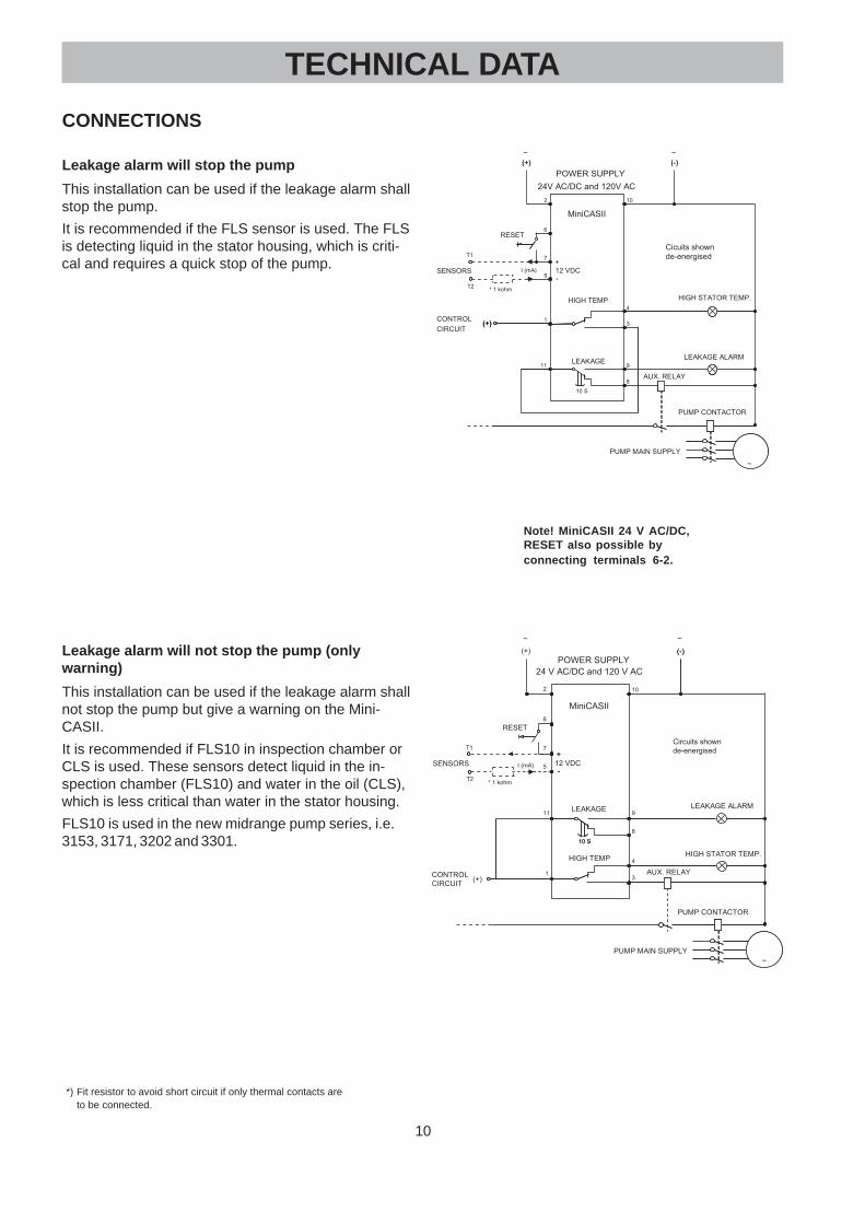
Note! MiniCASII 24 V AC/DC, RESET also possible by connecting terminals 6-2.
3
INSTALLATIONThe monitoring connections at the panel
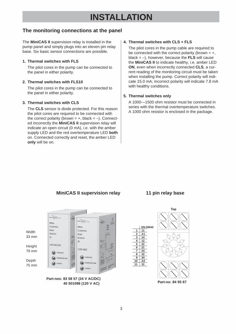
The MiniCAS II supervision relay is installed in thepump panel and simply plugs into an eleven pin relaybase. Six basic sensor connections are possible.
1. Thermal switches with FLS
The pilot cores in the pump can be connected tothe panel in either polarity.
2. Thermal switches with FLS10
The pilot cores in the pump can be connected tothe panel in either polarity.
3. Thermal switches with CLS
The CLS sensor is diode protected. For this reasonthe pilot cores are required to be connected withthe correct polarity (brown = +, black = –). Connect-ed incorrectly the MiniCAS II supervision relay willindicate an open circuit (0 mA), i.e. with the ambersupply LED and the red overtemperature LED bothon. Connected correctly and reset, the amber LEDonly will be on.
4. Thermal switches with CLS + FLS
The pilot cores in the pump cable are required tobe connected with the correct polarity (brown = +,black = –), however, because the FLS will causethe MiniCAS II to indicate healthy, i.e. amber LEDON, even when incorrectly connected CLS, a cur-rent reading of the monitoring circuit must be takenwhen installing the pump. Correct polarity will indi-cate 15.0 mA; incorrect polarity will indicate 7.8 mAwith healthy conditions.
5. Thermal switches only
A 1000—1500 ohm resistor must be connected inseries with the thermal overtemperature switches.A 1000 ohm resistor is enclosed in the package.
Top
MINI
ControlAndStatusII
79mm
33mm
LEAKAGE
TEMPERATURE
SUPPLY
75mm
Part-no: 84 55 67
EN 500421 112 A13 144 125 226 217 248 329 34
10 A211 31
MiniCAS II supervision relay 11 pin relay base
Part-nos: 83 58 57 (24 V AC/DC) 40 501098 (120 V AC)
Width33 mm
Height79 mm
Depth75 mm
4
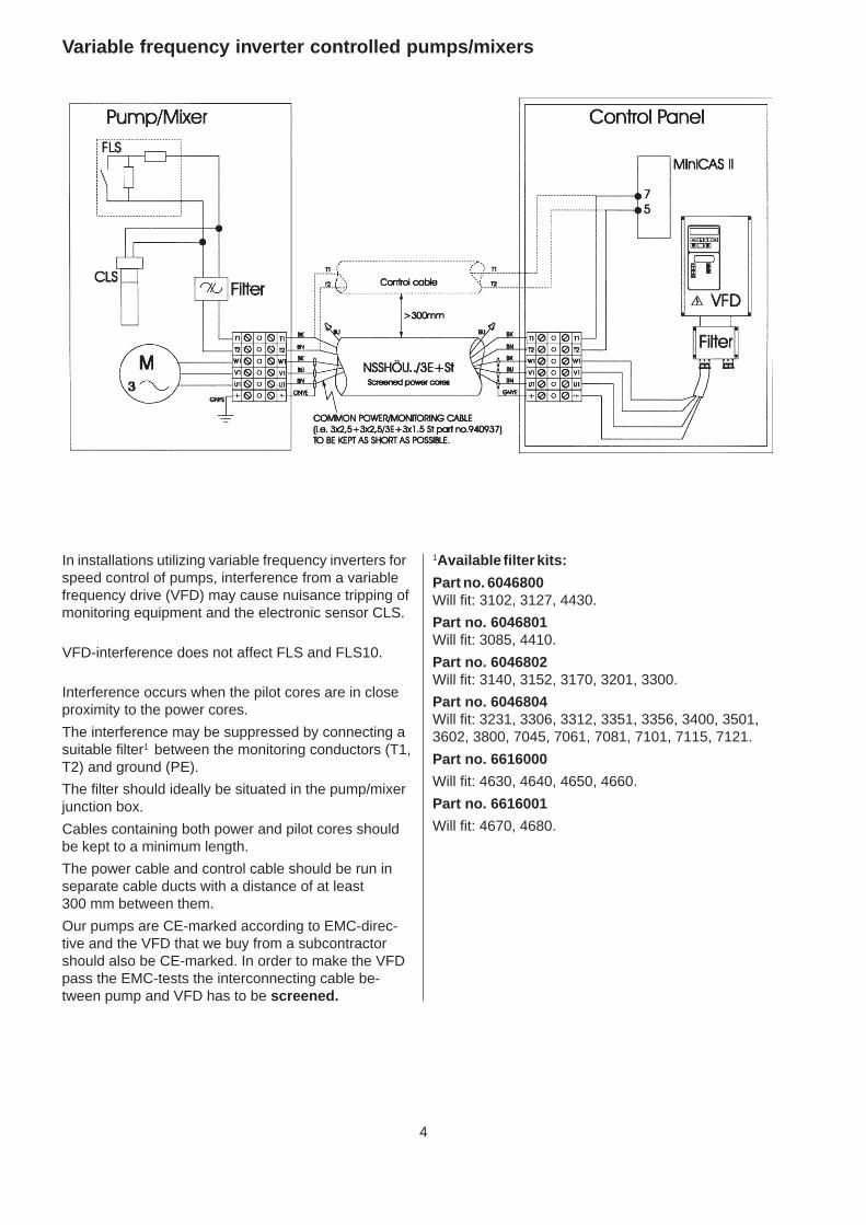
Variable frequency inverter controlled pumps/mixers
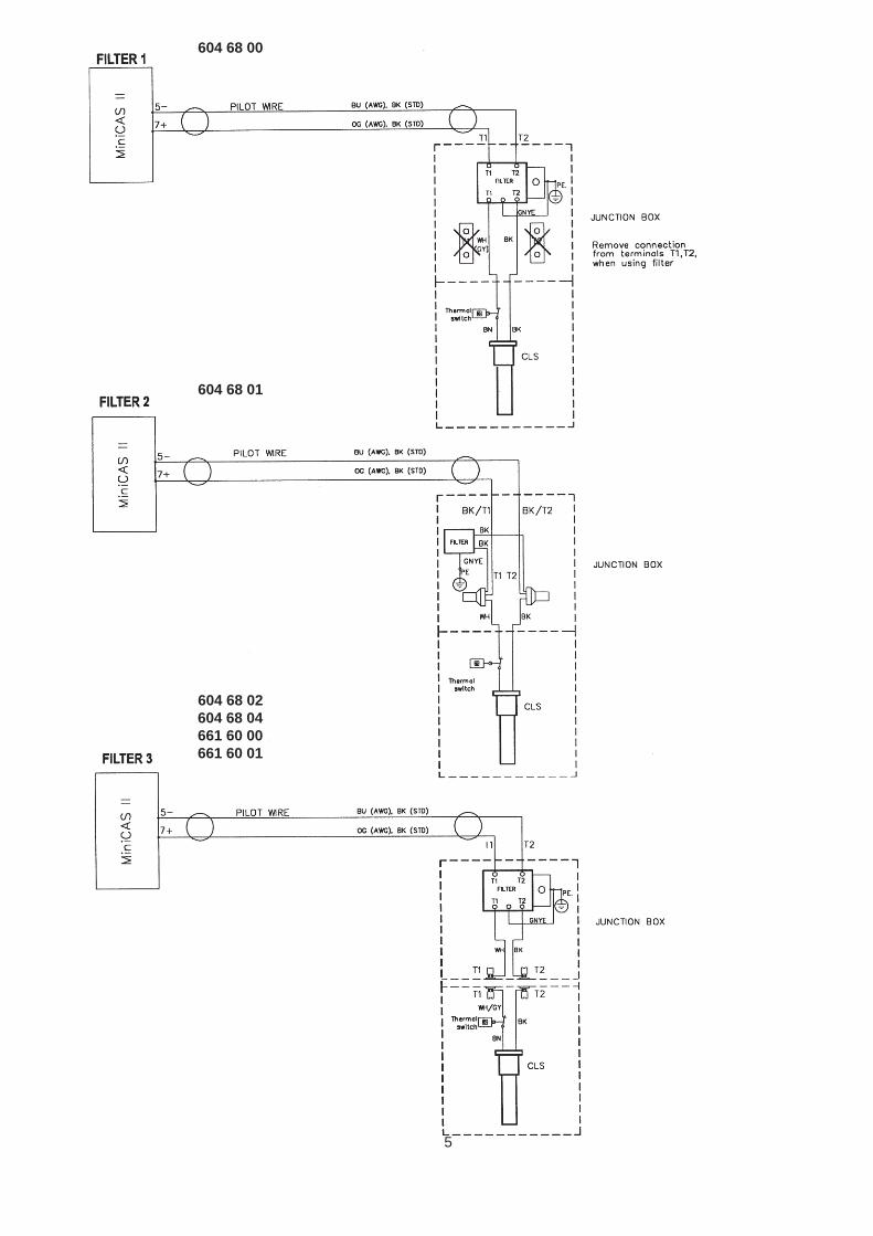
In installations utilizing variable frequency inverters forspeed control of pumps, interference from a variablefrequency drive (VFD) may cause nuisance tripping ofmonitoring equipment and the electronic sensor CLS.
VFD-interference does not affect FLS and FLS10.
Interference occurs when the pilot cores are in closeproximity to the power cores.
The interference may be suppressed by connecting asuitable filter1 between the monitoring conductors (T1,T2) and ground (PE).
The filter should ideally be situated in the pump/mixerjunction box.
Cables containing both power and pilot cores shouldbe kept to a minimum length.
The power cable and control cable should be run inseparate cable ducts with a distance of at least300 mm between them.
Our pumps are CE-marked according to EMC-direc-tive and the VFD that we buy from a subcontractorshould also be CE-marked. In order to make the VFDpass the EMC-tests the interconnecting cable be-tween pump and VFD has to be screened.
1Available filter kits:
Part no. 6046800Will fit: 3102, 3127, 4430.
Part no. 6046801Will fit: 3085, 4410.
Part no. 6046802Will fit: 3140, 3152, 3170, 3201, 3300.
Part no. 6046804Will fit: 3231, 3306, 3312, 3351, 3356, 3400, 3501,3602, 3800, 7045, 7061, 7081, 7101, 7115, 7121.
Part no. 6616000
Will fit: 4630, 4640, 4650, 4660.
Part no. 6616001
Will fit: 4670, 4680.
5
604 68 00
604 68 01
604 68 02604 68 04661 60 00661 60 01
6
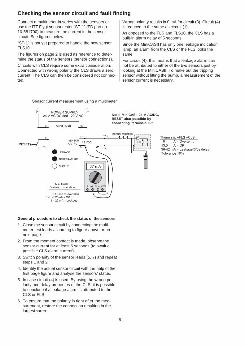
Connect a multimeter in series with the sensors oruse the ITT Flygt sensor tester “ST-1” (FD part no.10-581700) to measure the current in the sensorcircuit. See figures below.
“ST-1” is not yet prepared to handle the new sensorFLS10.
The figures on page 2 is used as reference to deter-mine the status of the sensors (sensor connections).
Circuits with CLS require some extra consideration.Connected with wrong polarity the CLS draws a zerocurrent. The CLS can then be considered not connec-ted.
Wrong polarity results in 0 mA for circuit (3). Circuit (4)is reduced to the same as circuit (1).
As opposed to the FLS and FLS10, the CLS has abuilt-in alarm delay of 5 seconds.
Since the MiniCASII has only one leakage indicationlamp, an alarm from the CLS or the FLS looks thesame.
For circuit (4), this means that a leakage alarm cannot be attributed to either of the two sensors just bylooking at the MiniCASII. To make out the trippingsensor without lifting the pump, a measurement of thesensor current is necessary.
General procedure to check the status of the sensors
1. Close the sensor circuit by connecting the multi-meter test leads according to figure above or onnext page.
2. From the moment contact is made, observe thesensor current for at least 5 seconds (to await apossible CLS alarm current).
3. Switch polarity of the sensor leads (5, 7) and repeatsteps 1 and 2.
4. Identify the actual sensor circuit with the help of thefirst page figure and analyse the sensors’ status.
5. In case circuit (4) is used: By using the wrong po-larity and delay properties of the CLS, it is possibleto conclude if a leakage alarm is attributed to theCLS or FLS.
6. To ensure that the polarity is right after the mea-surement, restore the connection resulting in thelargest current.
Checking the sensor circuit and fault finding
Sensor current measurement using a multimeter
thermal switchesT1+
T2-
330
1,2 k
RESET
6
2
POWER SUPPLY24 V AC/DC and 120 V AC
12 VDC
7+
5-
10
37 mA
A mA Com V/W
37 mA
A mA Com V/W
7+
Therm sw. +FLS +CLS
0 mA = Overtemp
13,3 mA = OK
36-42 mA = Leakage(0/5s delay)
Tolerance 10%
MiniCASII
SENSOR
OUTPUT
SUPPLY
LEAKAGE
TEMPERATURE
Mini CASII
Values of operation
I < 3 mA = Overtemp
3 < I < 22 mA = OK
I > 22 mA = Leakage
~~(-)(+)
RESET
Note! MiniCASII 24 V AC/DC,RESET also possible byconnecting terminals 6-2.
7
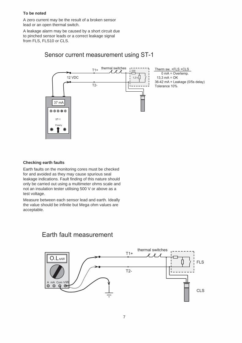
Checking earth faults
Earth faults on the monitoring cores must be checkedfor and avoided as they may cause spurious sealleakage indications. Fault finding of this nature shouldonly be carried out using a multimeter ohms scale andnot an insulation tester utilising 500 V or above as atest voltage.
Measure between each sensor lead and earth. Ideallythe value should be infinite but Mega ohm values areacceptable.
Sensor current measurement using ST-1
thermal switchesT1+
T2-
330
1,2 k
37 mA
Polarity
ST-1
330
1,2 k12 VDC
37 mA
Polarity
ST-1
Therm sw. +FLS +CLS
0 mA = Overtemp.
13,3 mA = OK
36-42 mA = Leakage (0/5s delay)
Tolerance 10%
To be noted
A zero current may be the result of a broken sensorlead or an open thermal switch.
A leakage alarm may be caused by a short circuit dueto pinched sensor leads or a correct leakage signalfrom FLS, FLS10 or CLS.
Earth fault measurement
thermal switchesT1+
T2-
O.L MW
A mA Com V/W
FLS
CLS
O.L MW
A mA Com V/W
O.LMW
A mA Com V/W
8
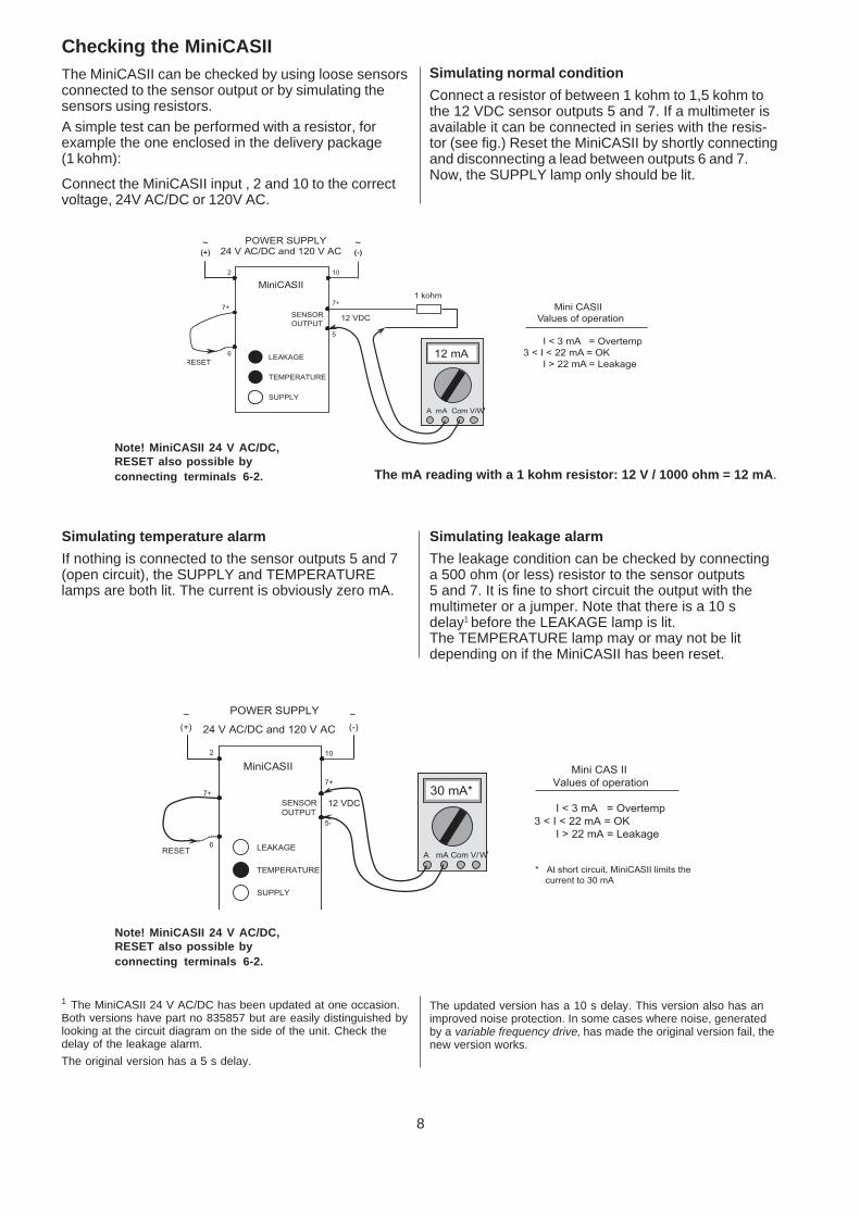
Checking the MiniCASIIThe MiniCASII can be checked by using loose sensorsconnected to the sensor output or by simulating thesensors using resistors.A simple test can be performed with a resistor, forexample the one enclosed in the delivery package(1 kohm):
Connect the MiniCASII input , 2 and 10 to the correctvoltage, 24V AC/DC or 120V AC.
Simulating temperature alarm
If nothing is connected to the sensor outputs 5 and 7(open circuit), the SUPPLY and TEMPERATURElamps are both lit. The current is obviously zero mA.
1 The MiniCASII 24 V AC/DC has been updated at one occasion.Both versions have part no 835857 but are easily distinguished bylooking at the circuit diagram on the side of the unit. Check thedelay of the leakage alarm.
The original version has a 5 s delay.
Simulating normal condition
Connect a resistor of between 1 kohm to 1,5 kohm tothe 12 VDC sensor outputs 5 and 7. If a multimeter isavailable it can be connected in series with the resis-tor (see fig.) Reset the MiniCASII by shortly connectingand disconnecting a lead between outputs 6 and 7.Now, the SUPPLY lamp only should be lit.
Simulating leakage alarm
The leakage condition can be checked by connectinga 500 ohm (or less) resistor to the sensor outputs5 and 7. It is fine to short circuit the output with themultimeter or a jumper. Note that there is a 10 sdelay1 before the LEAKAGE lamp is lit.The TEMPERATURE lamp may or may not be litdepending on if the MiniCASII has been reset.
6
2
(-)
12 VDC
7+
5-
MiniCASII
SENSOR
OUTPUT
(+)
10
30 mA*
A mA Com V/W
SUPPLY
LEAKAGE
TEMPERATURE
RESET
POWER SUPPLY
24 V AC/DC and 120 V AC
7+ 30 mA*
A mA Com V/W
30 mA*
A mA Com V/W
* At short circuit, MiniCASII limits the
current to 30 mA
~~
Mini CAS II
Values of operation
I < 3 mA = Overtemp
3 < I < 22 mA = OK
I > 22 mA = Leakage
The mA reading with a 1 kohm resistor: 12 V / 1000 ohm = 12 mA.
RESET
6
2
(-)
7+
5
MiniCASII
SENSOR
OUTPUT
(+)
10
12 mA
A mA Com V/W
SUPPLY
TEMPERATURE
POWER SUPPLY24 V AC/DC and 120 V AC (-)
12 VDC
7+
(+)
12 mA
A mA Com V/W
12 mA
A mA Com V/W
LEAKAGE
1 kohm
~~
Mini CASII
Values of operation
I < 3 mA = Overtemp
3 < I < 22 mA = OK
I > 22 mA = Leakage
The updated version has a 10 s delay. This version also has animproved noise protection. In some cases where noise, generatedby a variable frequency drive, has made the original version fail, thenew version works.
Note! MiniCASII 24 V AC/DC,RESET also possible byconnecting terminals 6-2.
Note! MiniCASII 24 V AC/DC,RESET also possible byconnecting terminals 6-2.

9
MiniCAS II supervision relayOperational principle: Current Sensing
Approvals: CE, C-UR (covering USA and Canada) and CSA
Environment: –25 to 60°C (maximum 90% relative humidity)
Supply voltage 24 V AC/DC: 20-30 V AC (50-60Hz)23.5–30 V DC
Supply voltage 120 V AC: 120 V AC (50-60 Hz)Relay contact rating: 250 V AC / 5A
Voltage to sensor: 12 V DC +/–5%
Values of operation: 3mA < I < 22 mA = OK conditionI < 3 mA = High temperature (or interruption)I > 22 mA = Leakage (or short circuit), 10 s delay of alarm
( I = current measured by MiniCAS II )
Power supply required: 5 VA
OPERATION
Leakage: Changeover contacts 11–8 Normally closed for interlock11–9 Closes for alarm
Automatic resetRed LED for indication – follows the relayRed indication lamp on: LeakageRed indication lamp off: No leakage
Temperature: Changeover contacts 1–3 Closes for interlock when energized1–4 Normally closed for alarm
Manual reset (see below)Red indication lamp on: Over temperatureRed indication lamp off: Normal temperature
Reset of Temperature Alarm: External reset is possible either by connecting terminals 6-7 with an externalpush button or by interrupting the supply voltage.
Note, in the 24 V version, Reset is also possible between 6-2.
DIMENSIONS: Width 33 mm
Height 79 mm
Depth 75 mm
PART NOS: 83 58 57 (24 V AC/DC)
40 501098 (120 V AC)
TECHNICAL DATA
10
CONNECTIONS
Leakage alarm will stop the pump
This installation can be used if the leakage alarm shallstop the pump.
It is recommended if the FLS sensor is used. The FLSis detecting liquid in the stator housing, which is criti-cal and requires a quick stop of the pump.
Leakage alarm will not stop the pump (onlywarning)
This installation can be used if the leakage alarm shallnot stop the pump but give a warning on the Mini-CASII.
It is recommended if FLS10 in inspection chamber orCLS is used. These sensors detect liquid in the in-spection chamber (FLS10) and water in the oil (CLS),which is less critical than water in the stator housing.
FLS10 is used in the new midrange pump series, i.e.3153, 3171, 3202 and 3301.
**) Fit resistor to avoid short circuit if only thermal contacts areto be connected.
TECHNICAL DATA
RESET
(+)
HIGH STATOR TEMP.
LEAKAGE ALARM
PUMP MAIN SUPPLY
(+)CONTROL
CIRCUIT
LEAKAGE
10 S
AUX. RELAY
HIGH TEMP
PUMP CONTACTOR
(-)
12 VDC
T2
T1
SENSORS
+
-
POWER SUPPLY
24V AC/DC and 120V AC
I (mA)
2
(+)
10
(+)(+)
(-)
6
7
5
1
11
4
3
9
8
~~
Cicuits shown
de-energised
* 1 kohm
MiniCASII
~
LEAKAGE
10 S
HIGH TEMP
POWER SUPPLY
24 V AC/DC and 120 V AC
(+)
HIGH STATOR TEMP.
LEAKAGE ALARM
PUMP MAIN SUPPLY
CONTROL
CIRCUIT
PUMP CONTACTOR
(-)
T2
T1
SENSORS
AUX. RELAY
12 VDC
+
-
RESET
10 S
10
(+)
(-)
2
6
7
5
11
1
9
8
4
3
+
-
~
MiniCASII
Circuits shown
de-energised
* 1 kohm
I (mA)
~
~
Note! MiniCASII 24 V AC/DC,RESET also possible byconnecting terminals 6-2.

11
TECHNICAL DATAFLS stator leakage sensorSignal: 8 mA non-alarm current,
36 mA alarm current
Supply voltage: 12 VDC
Max. duty temperature: 90°C
Material: Aluminium
Physical size, sensor
Length: 27 mm
Width: 16 mm
Height: 16 mm
Part Number 518 89 02
CLS water in oil sensorTrip emulsion: 35% of water in oil
Signal: 5.5 mA non-alarm current,29mA alarm current(5 s delay of alarm)
Poles: 2 wires protected with adiode (wrong polarityconnection = 0 mA)
Supply voltage: 12 VDC (± 10 %)(brown = +. black = –)
Metal parts: Acid proof stainless steel
Sensor surface: Glass
Max. pressure: 10 MPa 1h
Test pressure: 40 MPa
Duty pressure: 2 MPa
Max. temperature: 90°C, 1h
Test temperature: 115°C, 1h
Max. duty temperature 70°C
Physical size, sensor
Length: 75 mm
Diameter: 12 mm
Thread: M16 × 1.5, length 15 mm
Part number: 505 12 00
Warning: Sensor body made of glass.Handle with care.
FLS10 inspection chamber sensorSignal: 10 mA non-alarm current,
28 mA alarm current
Supply voltage: 12VDC
Max. duty temperature: 90°C
Material: Stainless steel andnitril rubber
Physical size, sensor
Length: 44 mm
Diameter: 22 mm
Thread: M12 × 1, length 9 mm
Part number 608 26 00

www.flygt.com
CLS
/FLS
/FLS
10/M
iniC
AS I
I.01.1
0.
En
g.
XM
. 06.0
5 ©
ITT F
LYG
T A
B P
rin
ted
in
Sw
ed
en
892472