Embed Size (px)
Citation preview


User Manual CM70
Page 2 of 38
Contents
Specifications …………………………………………………………………………………………………………………….3 Control and Operation ……………....……………………………………………………………………………………4-8 Installation …………………………………………………………………………………………………………………………9 Installation of Main Unit ………………………………………………………………………………………………………9 Antenna Installation …..……………………………………………………………………………………………………….9 Frequency Bands Table ……………………………………………………………………………………………………..10 Frequency Band Selection ………………………………………………………………………………………………….10 Table of Restrictions …………………………………………………………………………………………………………11 Updated Information on National Restrictions ……………………………………………………………………..12 Diagrams ………………………………………..………………………………………………………………………....13-17 Declaration of Conformity ………………………………………………………………………………..………………..18
Engl
ish

User Manual CM70
Page 3 of 38
Specifications
General Channels………………………………………..………...……………………………......…. 40 Ch AM/FM 4W Frequency Range….………………………………….………….…...…………..….26.565 to 27.99125 MHz Frequency Control……………………………………………….……………………………..…………………PLL Operating Temperature Range……………………………………………..………………….….-10° / +55°C DC Input Voltage……………………...…………………………………...………..............…13.2 V DC ±15% Size…………………………………….………………………………………..….182(L) X 37(H) X 139(D) mm Weight…………………………………………………………………………………...……………………0.850 kg
Receiver Receiving System…………………………………………………….….Dual Conversion Super Heterodyne Intermediate Frequency……………………………….…….……….1st IF: 10.695 MHz, 2nd IF: 455 MHZ Sensitivity………………………………………………..……………….0.5 μV for 20 db SINAD in FM mode Audio Distortion………………………………………………………………………….Less than 8% @ 1 KHz Image Rejection………………………………………………………………………………………………...65dB Adjacent Channel Rejection………………………………………………………………………………….65dB Signal/ Noise Ratio……………………………………………………………………………………………..45dB Current Drain at standby……………………………………..……………….……………………….....250 mA Current Drain at maximum audio…………………………….…………………………………………650 mA
Transmitter Output Power…………………………………………………………………………..……...….4W @ 13.2 V DC Modulation…………………………………………………..……………………...………FM: 1.8 KHz ±0.2 KHz Frequency response……………………..……………..…….………………..……...From 400 Hz to 2.5 KHz Output impedance……………………………………………………...…………………RF 50 ohm Unbalance Signal/ Noise Ratio……………………………………………………………….……………………..40 dB MIN Current Drain……………………………………………………………………………….……………….1200 mA
SS S pp p ee e cc c ii i ff f ii i cc c aa a tt t ii i oo o nn n
Engl
ish

User Manual CM70
Page 4 of 38
Control and Operation
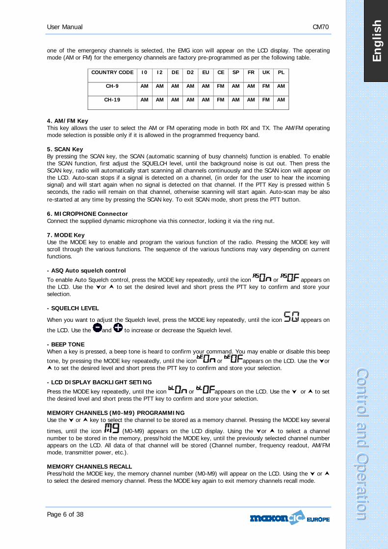
Front Panel
1. Power On/Off This knob switches the radio ON and OFF. 2. LCD Display This large, red backlit system allows clear readability. The LCD display shows all enabled functions as well as several other features (programmable by the user), such as the channel readout or the full 5-digit frequency readout. It also includes a digital 10-bar S/RF Meter to monitor the strength/power of received and transmitted signals. A. VOL Icon The VOL icon is visible when adjustments are made to the volume control. B. ESP C E Icon The ESP icon is visible when the ESP (Electronic Speech Processor) function is enabled.
CC C oo o nn n tt t rr r oo o ll l aa a nn n dd d OO Opp p ee e rr r aa a tt t ii i oo o nn n
Engl
ish

User Manual CM70
Page 5 of 38
C. LOCK Icon The LOCK icon is visible when the LOCK function has been enabled. D. AM Icon The AM icon is visible when the radio receives and transmits in AM mode (amplitude modulation). E. FM Icon The FM icon is visible when radio receives and transmits in FM mode (frequency modulation). F. DW Icon The DW icon is visible when the DUAL WATCH function (automatic monitoring of two channels) is enabled. The DW (Dual Watch) function allows automatic alternate monitoring of two programmable channels. Select the first channel to be monitored using the and or the channel selection keys on the microphone. To enable the DW function, press/hold the EMG key until the DW icon appears and blinks on the LCD display. Now select the second channel to monitor using the and or the channel selection keys on the microphone. Press/hold the EMG key. The DW function is now enabled and the LCD display will alternately show the channel number of the two programmed channels. The DW icon will be visible on the LCD display. Monitoring stops if a signal is detected on one of the two channels, in order to let the user listen to the incoming signal and will start again when no signal is detected on that channel. It is possible to transmit on that channel by simply pressing the PTT key. If there is no transmission within 5 seconds, monitoring will re-start. To exit the DW mode, short press the PTT button. G. H. I. Alphanumeric Digit G. These two alphanumeric digits indicate the country code, in accordance with the programmed frequency band (i.e. DE, UK, CE, etc.). H. I. These three alphanumeric digits indicate the operating channel number (01 to 80, according to the programmed frequency band), when the channel number readout function is enabled J. ASQ Icon The ASQ icon is visible when Auto Squelch enabled. K. LO Icon The LO icon is visible when the transmitter is in LOW POWER (1W) mode. L. TX Icon The TX icon is visible when radio is in transmit mode. M. RX Icon The RX icon is visible when radio is in receive mode. N. SQ Icon The SQ icon is visible when adjusting the squelch control. O. VOLUME / SQUELCH Digital Level Icon A digital 10-bar indicator displays the level of the volume and squelch. P. S/RF Digital meter A digital 10-bar S/RF METER indicates the strength of the received signal (from S0 to S9+30) in receive mode and transmitter RF output power (0 to 4W) in transmit mode. Q. EMG Icon The EMG icon is visible when one of the pre-programmed emergency channels has been selected. R. SCAN Icon The SCAN icon is visible when the SCAN function (automatic search of busy channels) is enabled. 3. EMG (Emergency Channels) Key This key allows quick access to one of the two pre-programmed emergency channels (CH9 or CH19). Each time this key is pressed, radio will select CH9, then CH19, then again the normal operating channel. When
CC C oo o nn n tt t rr r oo o ll l aa a nn n dd d OO Opp p ee e rr r aa a tt t ii i oo o nn n
Engl
ish
User Manual CM70
Page 6 of 38
one of the emergency channels is selected, the EMG icon will appear on the LCD display. The operating mode (AM or FM) for the emergency channels are factory pre-programmed as per the following table.
COUNTRY CODE I0 I2 DE D2 EU CE SP FR UK PL
CH-9 AM AM AM AM AM FM AM AM FM AM
CH-19 AM AM AM AM AM FM AM AM FM AM
4. AM/FM Key This key allows the user to select the AM or FM operating mode in both RX and TX. The AM/FM operating mode selection is possible only if it is allowed in the programmed frequency band. 5. SCAN Key By pressing the SCAN key, the SCAN (automatic scanning of busy channels) function is enabled. To enable the SCAN function, first adjust the SQUELCH level, until the background noise is cut out. Then press the SCAN key, radio will automatically start scanning all channels continuously and the SCAN icon will appear on the LCD. Auto-scan stops if a signal is detected on a channel, (in order for the user to hear the incoming signal) and will start again when no signal is detected on that channel. If the PTT Key is pressed within 5 seconds, the radio will remain on that channel, otherwise scanning will start again. Auto-scan may be also re-started at any time by pressing the SCAN key. To exit SCAN mode, short press the PTT button. 6. MICROPHONE Connector Connect the supplied dynamic microphone via this connector, locking it via the ring nut. 7. MODE Key Use the MODE key to enable and program the various function of the radio. Pressing the MODE key will scroll through the various functions. The sequence of the various functions may vary depending on current functions. - ASQ Auto squelch control To enable Auto Squelch control, press the MODE key repeatedly, until the icon or appears on the LCD. Use the or to set the desired level and short press the PTT key to confirm and store your selection. - SQUELCH LEVEL
When you want to adjust the Squelch level, press the MODE key repeatedly, until the icon appears on
the LCD. Use the and to increase or decrease the Squelch level. - BEEP TONE When a key is pressed, a beep tone is heard to confirm your command. You may enable or disable this beep
tone, by pressing the MODE key repeatedly, until the icon or appears on the LCD. Use the or to set the desired level and short press the PTT key to confirm and store your selection.
- LCD DISPLAY BACKLIGHT SETING Press the MODE key repeatedly, until the icon or appears on the LCD. Use the or to set the desired level and short press the PTT key to confirm and store your selection. MEMORY CHANNELS (M0-M9) PROGRAMMING Use the or key to select the channel to be stored as a memory channel. Pressing the MODE key several
times, until the icon (M0-M9) appears on the LCD display. Using the or to select a channel number to be stored in the memory, press/hold the MODE key, until the previously selected channel number appears on the LCD. All data of that channel will be stored (Channel number, frequency readout, AM/FM mode, transmitter power, etc.). MEMORY CHANNELS RECALL Press/hold the MODE key, the memory channel number (M0-M9) will appear on the LCD. Using the or to select the desired memory channel. Press the MODE key again to exit memory channels recall mode.
CC C oo o nn n tt t rr r oo o ll l aa a nn n dd d OO Opp p ee e rr r aa a tt t ii i oo o nn n
Engl
ish

User Manual CM70
Page 7 of 38
8. UP – Down SLIDE BAR
Use the and to increase or decrease Volume and Squelch level. 9. ESP (Electronic Speech Processor) Key The ESP (Electronic Speech Processor) is an exclusive advanced feature of the Maxon CM70 CB radio. ESP (Electronic Speech Processor), works as a modulation compressor during transmission and as a modulation expander during receive mode. The ESP obtains stronger, cleaner and clearer audio signals, great help in noisy areas especially in the case of long distance communication or weak signals. The efficiency of ESP is even greater when communicating with other radios using the same system. To enable or disable the ESP function, press the ESP key. When enabled, the ESP icon appears on the LCD display. ESP performance of the modulation in RX and TX modes 10. (Quick Down) Key This key allows fast selection of the operating channel downward. Each time this key is pressed, the channel number moves down by 1 channel. Press this key for about 2 seconds, the channel number moves down by 10 channels. 11. (Quick UP) Key This key allows fast selection of the operating channel in increments. Each time this key is pressed, the channel number moves up by 1 channel. Press/hold this key to move the channel number in groups of 10. Rear Panel 12. EXT (External Speaker) Jack This jack is for connecting an external speaker (optional). 13. S-METER Jack This jack is for connecting an external S-METER (optional). 14. ANTENNA Connector Antenna connector. Refer to the section INSTALLATION OF THE ANTENNA. 15. 13.8DC POWER CORD 13.8 DC power cord input.
CC C oo o nn n tt t rr r oo o ll l aa a nn n dd d OO Opp p ee e rr r aa a tt t ii i oo o nn n
Engl
ish

User Manual CM70
Page 8 of 38
MICROPHONE
16. PTT (Push-to-Talk) Key Transmitter key. Press the PTT key to transmit and release it to return to the receive mode. 17. UP (Channel Selector) Key Each time this key is pressed, the channel number will move upward by one channel. * Can be used instead of 18. LOCK/MODE Key The LOCK function is enabled by a press/hold of this key locks the keypad and prevents the activation of unwanted features. When the LOCK function is enabled, the LOCK icon appears on the LCD display. You can use this key to set ASQ, SQ, BEEP TONE, BACKLIGHT and MEMORY. This key is the same as the MODE Key on the front of the radio. * You can also use this key for increasing or decreasing volume level.
Pressing the LOCK/MODE key several times, until the icon or appears on the LCD. The UP KEY or DN Key on microphone can also be used to increase or decrease the volume level. 19. DOWN (Channel Selector) Key Each time this key is pressed, the channel number will move downward by one channel. * Can be used instead of 20. MICROPHONE Plug The 6-pin microphone plug with locking ring nut is connected to the microphone connector located on the front of the radio.
CC C oo o nn n tt t rr r oo o ll l aa a nn n dd d OO Opp p ee e rr r aa a tt t ii i oo o nn n
1916 17 18
20
Engl
ish

User Manual CM70
Page 9 of 38
Installation Before installing the main unit in a vehicle, check and select the most convenient location, so the radio will be easy to reach and comfortable to operate, without disturbing or interfering with operating the vehicle. Use the supplied bracket and hardware to install the radio. The bracket screws must be well tightened in order not to become loose with vehicle vibrations. The car mounting bracket can be installed above or below the radio and the radio may be tilted as desired according to the specific type of installation (under dashboard or track cabin roof installation).
Installation of Main Unit Before connecting the radio to the vehicles electrical system, ensure that radio is switched off. The DC power cable is complete with a fuse holder (fuse located on the red positive (+) wire). Connect the DC power cable to the vehicles electrical system, pay special attention to correct polarity, even if the radio is protected against polarity inversion. Connect the red wire to the positive (+) pole and the black wire to the negative (-) pole of the vehicles electrical system. Ensure that wires and terminals are firmly connected, in order to prevent cables from disconnecting or causing short circuits.
Installation of the Antenna A specific mobile antenna adjusted for 27 MHz frequency range must be used. The antenna installation must be carried out by a specialist technician or service centre. Please take special care to fully install the antenna on the vehicle with a perfect connection to ground. Before connecting the antenna to the radio, it is necessary to check the correct operation of the antenna with low standing wave ratio (S.W.R.), using adequate instruments. If not, the transmitter circuit of the radio could be damaged. The antenna is usually installed on the highest part of the vehicle, free from obstacles and as far away as possible from any source of electric or electromagnetic noise. The RF antenna coaxial cable must not be damaged or pressed on its way between antenna and the radio. The correct operation of the antenna and the low standing wave ratio (S.W.R.) must be checked periodically. Connect the RF antenna coaxial cable to the antenna Connector, located on the rear side of the radio.
Operational Test Once the radio has been connected to the vehicles power supply and the antenna is installed, the operation of the system can be check and tested. Please proceed as follows:
1.) Make sue the unit is installed correctly. 2.) Check that the power cable is fitted correctly. 3.) Check that RF antenna coaxial connector is correctly fitted. 4.) Fit the microphone to the front panel connector. 5.) Power on the unit and select correct Frequency band for country of use. (see page 10) 6.) Adjust the squelch to be open (noise from speaker) via mode key, select SQ and use or . 7.) Select desired channel using or . 8.) Press PTT (Push To Talk) to transmit and release to receive. If the test is successful the unit is ready to use. If you incur any problems please contact your dealer.
II I nn n ss s tt t aa a ll l ll l aa a tt t ii i oo o nn n
Engl
ish

User Manual CM70
Page 10 of 38
Frequency Bands Table The CM70 transceiver includes an advanced multi-standard programmable circuit, which allows the user to program different frequency bands, specifications and operating modes (in conformity with the regulations in the country where the product is being used). 10 programmable frequency bands are available, as per the below table:
COUNTRY CODE COUNTRY SPECIFICATIONS (CH, operating
modes, TX power) I0 ITALY 40CH AM / FM 4W I2 ITALY 36CH AM / FM 4W DE GERMANY 80CH FM 4W - 12CH AM 1W D2 GERMANY 40CH FM 4W - 12CH AM 1W EU EUROPE 40CH FM 4W - 40CH AM 1W CE CEPT 40CH FM 4W SP SPAIN 40CH AM / FM 4W FR FRANCE 40CH FM 4W - 40CH AM 1W
UK UK 40CH FM 4W UK FREQUENCIES -40CH FM 4W CEPT FREQUENCIES
PL POLAND 40CH AM / FM 4W POLISH FREQUENCIES
Attention! This radio has been factory pre-programmed on the CE frequency band (CEPT 40CH FM 4W), since this standard is currently accepted in all the European countries. Please refer to the information table (Restrictions on the use of CB transceivers).
Frequency Band Selection/Programming The radio must be programmed and used exclusively on a frequency band allowed in the country where the product is used. It is possible to program a different frequency band, as per the following procedures: 1) Switch off the radio. 2) Press and hold the EMG key while turning on the radio, using the Power knob – Release while all displayed icons are still lit. 3) The current country code will blink on the LCD display (2 digits). 4) Now select the desired new country code, using the or . 5) Shortly press the EMG key to confirm.
Engl
ish

User Manual CM70
Page 11 of 38
Contenido
Especificaciones…………………………………………………………………………………………….…………………3 Control y utilización……………....……………………………………………………………………….………………4-8 Instalación………………………………………………………………………………………………………………………9 Instalación de la unidad principal………………………………………………………………………………………9 Instalación de la antena………………..………………………………………………………………………………….9 Tabla de bandas de frecuencia………………………………………………………………………………………..10 Selección de bandas de frecuencia……………………………………………………………………………………10 Tabla de restricciones…………………………………………………………………………………………………….11 Información actualizada sobre restricciones nacionales……………………………………………………..12 Diagramas…………………………………………………..…………………………………………………………....13-17 Declaración de conformidad…………………………………………………………………………..……………….18
Espa
ñol

User Manual CM70
Page 12 of 38
Especificaciones
Generales Canales………………………………………..…………...……………………………....40 canales AM/FM 4W Rango de frecuencias….……………………………………….………….…...…………..26.565 a 27.99125 MHz Control de frecuencia……………………………………………….……………………………..……………PLL Rango de temperaturas de funcionamiento………………………………………..……….-10° / +55°C Tensión de entrada de CC……………………...………………………………...……......…13,2 V CC ±15% Tamaño…………………………………….……………………………………….182(L) X 37(A) X 139(P) mm Peso………………………………………………………………………………………...…………………0,850 kg
Receptor Sistema de recepción………………………………………………….Superheterodino de conversión dual Frecuencia intermedia …………………………………………….….1ª IF: 10.695 MHz, 2ª IF: 455 MHz Sensibilidad………………………………………………..………….0,5 μV para 20 db SINAD en modo FM Distorsión de sonido……………………………………………………………………Inferior al 8% @ 1 KHz Rechazo de imagen…………………………………………………………………………………………..65 dB Rechazo de canal adyacente……………………………………………………………………………….65 dB Relación señal/ruido………………………………………………………………………………………….45 dB Consumo de corriente en standby……………………………………..…………….…………………250 mA Consumo de corriente con máximo nivel de audio…………………………….……………………650 mA
Transmisor Potencia de salida…………………………………………………………………………..…….4W @ 13,2 V CC Modulación……………………………………………………..……………………...……FM: 1.8 KHz ±0.2 KHz Respuesta de frecuencia……………………..……………………..…….……………...De 400 Hz a 2.5 KHz Impedancia de salida…………………………………………………...………RF 50 ohmios, desequilibrio Relación señal/ruido………………………………………………………………….………………..40 dB MÍN Consumo de corriente………………………………………………………………………….……….1200 mA
EE E ss s pp p ee e cc c ii i ff f ii i cc c aa a cc c ii i oo o nn n ee e ss s
Espa
ñol
User Manual CM70
Page 13 of 38
Control y utilización
Panel delantero
1. Encendido/apagado Este control enciende y apaga la radio. 2. Pantalla LCD Esta pantalla grande y con iluminación posterior resulta fácilmente legible. La pantalla LCD muestra todas las funciones activadas, así como otras funciones (programables por el usuario), como la lectura de canales o la lectura de frecuencias completa de 5 dígitos. También incluye un medidor S/RF digital de 10 barras para supervisar la potencia de las señales recibida y transmitida. A. Icono VOL El icono VOL está visible cuando se realizan ajustes en el control de volumen. B. Icono ESP C E El icono ESP está visible cuando está activada la función ESP (Electronic Speech Processor: procesador electrónico de voz).
CC C oo o nn n tt t rr r oo o ll l yy y uu u tt t ii i ll l ii i zz z aa a cc c ii i óó ó nn nI
Espa
ñol

User Manual CM70
Page 14 of 38
C. Icono LOCK El icono LOCK está visible cuando está activada la función LOCK (bloqueo). D. Icono AM El icono AM está visible cuando la radio recibe y transmite en modo AM (modulación de amplitud). E. Icono FM El icono FM está visible cuando la radio recibe y transmite en modo FM (frecuencia modulada). F. Icono DW El icono DW está visible cuando está activada la función DUAL WATCH (supervisión dual: supervisión automática de dos canales). La función DW permite la supervisión alterna automática de dos canales programables. Seleccione el primer canal que debe supervisarse mediante y o los botones de selección de canal del micrófono. Para activar la función DW, mantenga pulsado el botón EMG hasta que el icono DW aparezca y parpadee en la pantalla LCD. Seguidamente, seleccione el segundo canal que debe supervisarse mediante y o los botones de selección de canal del micrófono. Mantenga pulsado el botón EMG. La función DW quedará activada y la pantalla LCD mostrará de forma alterna los números de los dos canales programados. El icono DW estará visible en la pantalla LCD. La supervisión se detiene si se detecta una señal en uno de los dos canales, con el fin de permitir al usuario escuchar la señal entrante, y comenzará de nuevo cuando no se detecte ninguna señal en dicho canal. Es posible transmitir en dicho canal simplemente pulsando el botón PTT. Si no hay transmisión en 5 segundos, se reiniciará la supervisión. Para salir del modo DW, pulse brevemente el botón PTT. G. H. I. Dígito alfanumérico G. Estos dos dígitos alfanuméricos indican el código de país conforme a la banda de frecuencias programada (es decir, DE, UK, CE, etc.). H. I. Estos tres dígitos alfanuméricos indican el número del canal operativo (de 01 a 80, en función de la banda de frecuencias programada), cuando está activada la función de lectura del número de canal. J. Icono ASQ El icono ASQ está visible cuando está activada la función Auto Squelch (silenciador automático). K. Icono LO El icono LO está visible cuando el transmisor está en modo LOW POWER (baja potencia: 1W). L. Icono TX El icono TX está visible cuando la radio está en modo de transmisión. M. Icono RX El icono RX está visible cuando la radio está en modo de recepción. N. Icono SQ El icono SQ está visible al ajustar el control de silenciador. O. Icono de nivel digital de volumen / silenciador Indicador digital de 10 barras que muestra el nivel del volumen y el silenciador. P. Medidor digital de S/RF Medidor S/RF digital de 10 barras que indica la potencia de la señal recibida (de S0 a S9+30) en modo de recepción y la potencia de salida RF del transmisor (de 0 a 4W) en modo de transmisión. Q. Icono EMG El icono EMG está visible cuando se selecciona uno de los canales de emergencia preprogramados. R. Icono SCAN El icono SCAN está visible cuando está activada la función SCAN (búsqueda automática de canales ocupados).
CC C oo o nn n tt t rr r oo o ll l yy y uu u tt t ii i ll l ii i zz z aa a cc c ii i óó ó nn n
Espa
ñol

User Manual CM70
Page 15 of 38
3. Botón EMG (canales de emergencia) Este botón permite un acceso rápido a uno de los dos canales de emergencia preprogramados (CH9 o CH19). Cada vez que se pulsa este botón, la radio selecciona CH9, luego CH19 y, después, de nuevo el canal de funcionamiento normal. Cuando se selecciona uno de los canales de emergencia, aparece el icono EMG en la pantalla LCD. El modo de funcionamiento (AM o FM) para los canales de emergencia está preprogramado en fábrica conforme a la siguiente tabla.
CÓDIGO DE
PAÍS I0 I2 DE D2 EU CE SP FR UK PL
CH-9 AM AM AM AM AM FM AM AM FM AM
CH-19 AM AM AM AM AM FM AM AM FM AM
4. Botón AM/FM Este botón permite al usuario seleccionar el modo de funcionamiento en AM o FM tanto en RX como en TX. La selección de modo de funcionamiento AM/FM sólo es posible si se permite en la banda de frecuencias programada. 5. Botón SCAN Al pulsar el botón SCAN, se activa la función SCAN (búsqueda automática de canales ocupados). Para activar la función SCAN, ajuste en primer lugar el nivel de SQUELCH (silenciador) hasta que se corte el ruido de fondo. Seguidamente, pulse el botón SCAN, tras lo cual la radio comenzará a buscar automáticamente todos los canales de manera continua y se mostrará el icono SCAN en el LCD. La búsqueda automática se detendrá si se detecta una señal en un canal (con el fin de permitir al usuario escuchar la señal entrante) y comenzará de nuevo cuando no se detecte ninguna señal en dicho canal. Si se pulsa el botón PTT antes de que transcurran 5 segundos, la radio permanecerá en dicho canal. De lo contrario, la búsqueda comenzará de nuevo. La búsqueda automática también puede reiniciarse en cualquier momento pulsando el botón SCAN. Para salir del modo SCAN, pulse brevemente el botón PTT. 6. Conector para micrófono Conecte el micrófono dinámico suministrado a través de este conector y bloquéelo mediante la tuerca de anillo. 7. Botón MODE Utilice el botón MODE para activar y programar las diversas funciones de la radio. Pulsando la tecla MODE, se desplazará entre las distintas funciones. La secuencia de las funciones puede variar en función de las funciones actuales. - Control de silenciador automático ASQ Para activar el control de silenciador automático (Auto Squelch), pulse la tecla MODE repetidamente hasta que aparezca el icono o en la pantalla LCD. Utilice o para establecer el nivel deseado y pulse brevemente el botón PTT para confirmar y guardar la selección. - NIVEL DE SILENCIADOR Cuando desee ajustar el nivel de silenciador, pulse la tecla MODE repetidamente hasta que aparezca el icono
en la pantalla LCD. Utilice y para aumentar o reducir el nivel de silenciador. - TONO DE PITIDO Al pulsar un botón, suena un pitido para confirmar la orden. Puede activar o desactivar este tono de pitido pulsando la tecla MODE repetidamente hasta que aparezca el icono o en la pantalla LCD. Utilice o para establecer el nivel deseado y pulse brevemente el botón PTT para confirmar y guardar la selección. - AJUSTE DE LA ILUMINACIÓN POSTERIOR DE LA PANTALLA LCD Pulse la tecla MODE repetidamente hasta que aparezca el icono o en la pantalla LCD. Utilice o para establecer el nivel deseado y pulse brevemente el botón PTT para confirmar y guardar la selección.
Espa
ñol
CC Coo o nn n tt t rr r oo o ll l yy y uu u tt t ii i ll l ii i zz z aa a cc c ii i óó ó nn n

User Manual CM70
Page 16 of 38
PROGRAMACIÓN DE CANALES DE MEMORIA (M0-M9) Utilice el botón o para seleccionar el canal que debe almacenarse como canal de memoria. Pulse el
botón MODE repetidamente hasta que aparezca el icono (M0-M9) en la pantalla LCD. Utilice o para seleccionar el número de canal que desea almacenar en la memoria, mantenga pulsado el botón MODE hasta que aparezca en la pantalla LCD el número del canal previamente seleccionado. Se guardarán todos los datos de dicho canal (número de canal, lectura de frecuencia, modo AM/FM, potencia de transmisor, etc.). RECUPERACIÓN DE CANALES DE LA MEMORIA Pulse la tecla MODE para que aparezca el número de canal de la memoria (M0-M9) en la pantalla LCD. Utilice o para seleccionar el canal de memoria deseado. Pulse el botón MODE de nuevo para salir del modo de recuperación de canales de la memoria. 8. BARRA DESLIZANTE ARRIBA - ABAJO
Utilice y para aumentar o reducir el nivel de volumen y de silenciador. 9. Botón ESP (Electronic Speech Processor: procesador electrónico de voz) ESP (procesador electrónico de voz) es una función avanzada exclusiva de la radio Maxon CM70 CB. ESP funciona como compresor de modulación durante la transmisión y como expansor de modulación durante el modo de recepción. ESP obtiene señales de audio más potentes, limpias y claras, lo que es de gran ayuda en lugares ruidosos, y particularmente en el caso de comunicaciones a larga distancia o de señales débiles. La eficiencia de ESP es aun mayor al comunicar con otras radios que utilizan el mismo sistema. Para activar o desactivar la función ESP, pulse el botón ESP. Cuando esté activada, aparecerá el icono ESP en la pantalla LCD. Rendimiento ESP de la modulación en modos RX y TX 10. Botón (descenso rápido) Este botón permite la selección rápida del canal de funcionamiento hacia abajo. Cada vez que se pulsa este botón, se reduce en 1 el número de canal. Pulse este botón durante 2 segundos para bajar 10 canales. 11. Botón (aumento rápido) Este botón permite la selección rápida del canal de funcionamiento en incrementos. Cada vez que se pulsa este botón, aumenta en 1 el número de canal. Mantenga pulsado este botón para cambiar de 10 en 10 el número de canal. Panel posterior
CC C oo o nn n tt t rr r oo o ll l yy y uu u tt t ii i ll l ii i zz z aa a cc c ii i óó ó nn n
Espa
ñol

User Manual CM70
Page 17 of 38
12. Conector (de altavoz externo) EXT Este conector permite la conexión de un altavoz externo (opcional). 13. Conector S-METER Este conector permite la conexión de un S-METER externo (opcional). 14. Conector de antena (ANTENNA) Conector de antena. Consulte la sección INSTALACIÓN DE LA ANTENA. 15. CABLE DE CORRIENTE DE 13,8 VCC Entrada de cable de corriente de 13,8 VCC.
Espa
ñol

User Manual CM70
Page 18 of 38
MICRÓFONO
16. Botón PTT (Push-to-Talk) Botón de transmisor. Pulse el botón PTT para transmitir y suéltelo para regresar al modo de recepción. 17. Botón Arriba (selector de canal) Cada vez que se pulsa este botón, aumenta en 1 el número de canal. * Se puede utilizar en lugar de 18. Botón LOCK/MODE La función LOCK (bloqueo) se activa manteniendo pulsado este botón, con lo que se bloquea el teclado y se impide la activación no deseada de funciones. Cuando esté activada la función LOCK, aparecerá el icono LOCK en la pantalla LCD. Puede utilizar este botón para establecer ASQ (silenciador automático), SQ (nivel de silenciador), el tono de pitido, la iluminación posterior y la memoria. Este botón es el mismo que el botón MODE situado en la parte delantera de la radio. * También puede utilizar este botón para aumentar o reducir el nivel de volumen. Pulse el botón LOCK/MODE repetidamente hasta que aparezca el icono o en la pantalla LCD. También se pueden utilizar los botones UP o DN del micrófono para aumentar o reducir el nivel de volumen. 19. Botón Abajo (selector de canal) Cada vez que se pulsa este botón, se reduce en 1 el número de canal. * Se puede utilizar en lugar de 20. Conector para MICRÓFONO El conector para micrófono de 6 patillas con tuerca de anillo para bloqueo se conecta al conector para micrófono situado en la parte delantera de la radio.
CC C oo o nn n tt t rr r oo o ll l yy y uu u tt t ii i ll l ii i zz z aa a cc c ii i óó ó nn n
1916 17 18
20
Espa
ñol

User Manual CM70
Page 19 of 38
Instalación Antes de instalar la unidad principal en un vehículo, compruebe y seleccione el lugar más cómodo, de manera que la radio sea fácilmente accesible y se pueda operar con ella con comodidad y sin interferir en la conducción del vehículo. Utilice el soporte y el material suministrados para instalar la radio. Los tornillos del soporte deben apretarse bien para evitar que se suelten con las vibraciones del vehículo. El soporte para montaje en vehículo puede instalarse encima o debajo de la radio. La radio puede inclinarse como se desee para adaptarla al tipo de instalación de que se trate (instalación debajo del salpicadero o en el techo de la cabina de un camión).
Instalación de la unidad principal Antes de conectar la radio al sistema eléctrico del vehículo, asegúrese de que la radio está apagada. El cable de alimentación de CC está provisto de un portafusible (el fusible está situado en el hilo rojo positivo (+)). Conecte el cable de alimentación de CC al sistema eléctrico del vehículo. Preste especial atención a la polaridad aunque la radio disponga de protección contra inversiones de polaridad. Conecte el hilo rojo al polo positivo (+) y el hilo negro, al polo negativo (-) del sistema eléctrico del vehículo. Asegúrese de que los hilos y terminales están conectados de manera firme para evitar que los cables se desconecten o provoquen cortocircuitos.
Instalación de la antena Debe utilizarse una antena móvil específica ajustada al rango de frecuencias de 27 MHz. La instalación de la antena deberá realizarla un técnico o centro de servicio especializado. Tenga especial cuidado al instalar la antena en el vehículo para que ésta esté perfectamente conectada a tierra. Antes de conectar la antena a la radio, es necesario comprobar el correcto funcionamiento de la antena con baja relación de onda estacionaria (S.W.R.) mediante el uso de los instrumentos adecuados. De no ser así, podría dañarse el circuito del transmisor de la radio. La antena suele instalarse en la parte más alta del vehículo, libre de obstáculos y lo más alejada posible de cualquier fuente de electricidad o ruido electromagnético. El cable coaxial de la antena RF no debe dañarse ni presionarse en su tendido desde la antena hasta la radio. El correcto funcionamiento de la antena y la baja relación de onda estacionaria (S.W.R.) deberán comprobarse periódicamente. Conecte el cable coaxial de la antena RF al conector de antena, situado en la parte posterior de la radio.
Prueba de funcionamiento Una vez que la radio esté conectada a la fuente de alimentación del vehículo y que la antena esté instalada, podrá comprobarse el correcto funcionamiento del sistema. Proceda del siguiente modo:
9.) Asegúrese de que la unidad está correctamente instalada. 10.) Compruebe que el cable de alimentación esté correctamente conectado. 11.) Compruebe que el conector coaxial de antena RF esté correctamente ajustado. 12.) Conecte el micrófono al conector del panel delantero. 13.) Encienda la unidad y seleccione la banda de frecuencias correcta para el país en el que se va a
utilizar. (véase la página 10) 14.) Abra el silenciador (para que se reciba ruido del altavoz) mediante el botón MODE, seleccione SQ y
utilice o . 15.) Seleccione el canal deseado mediante o . 16.) Pulse el botón PTT (Push To Talk: pulsar para hablar) para transmitir y suéltelo para recibir. Si la prueba es correcta, la unidad está lista para ser utilizada. Si se produce algún problema, póngase en contacto con su distribuidor.
II I nn n ss s tt t aa a ll l aa a cc c ii i óó ó nn n
Espa
ñol

User Manual CM70
Page 20 of 38
Tabla de bandas de frecuencia El transceptor CM70 incluye un circuito programable multiestándar avanzado que permite al usuario programar diferentes bandas de frecuencia, especificaciones y modos de funcionamiento (de conformidad con la normativa del país en que se utilice el producto). Hay disponibles 10 bandas de frecuencias programables, conforme a la siguiente tabla:
CÓDIGO DE PAÍS PAÍS ESPECIFICACIONES (Canales, modos
operativos, potencia de TX) I0 ITALIA 40CH AM / FM 4W I2 ITALIA 36CH AM / FM 4W DE ALEMANIA 80CH FM 4W - 12CH AM 1W D2 ALEMANIA 40CH FM 4W - 12CH AM 1W EU EUROPA 40CH FM 4W - 40CH AM 1W CE CEPT 40CH FM 4W SP ESPAÑA 40CH AM / FM 4W FR FRANCIA 40CH FM 4W - 40CH AM 1W UK REINO UNIDO 40CH FM 4W FRECUENCIAS DE RU -40CH FM
4W FRECUENCIAS CEPT
PL POLONIA 40CH AM / FM 4W FRECUENCIAS POLACAS
¡Atención! Esta radio se ha preprogramado en fábrica en la banda de frecuencias CE (CEPT 40CH FM 4W), ya que este estándar es aceptado actualmente por todos los países europeos. Consulte la tabla informativa (Restricciones al uso de transceptores CB).
Selección/programación de bandas de frecuencia La radio debe programarse y utilizarse exclusivamente en una banda de frecuencias permitida en el país en el que se utiliza. Es posible programar otra banda de frecuencias diferente siguiendo este procedimiento: 1) Apague la radio. 2) Mantenga pulsado el botón EMG mientras enciende la radio, empleando el control de potencia. Suéltelo mientras están todavía iluminados todos los iconos mostrados. 3) El código de país actual parpadeará en la pantalla LCD (2 dígitos). 4) Seguidamente, seleccione el nuevo código de país que desee mediante o . 5) Pulse brevemente el botón EMG para confirmar.
Espa
ñol

User Manual CM70
Page 21 of 38
Sommario
Specifiche…....………………………………………………………………………………………………………….…………3 Comandi e operatività …….………....……………………………………………………………………………………4-8 Installazione ………………………………………………………………………………………………………………………9 Installazione dell'unità principale………..…………………………………………………………………………………9 Installazione dell'antenna ………………………………………………………………………………………...…………9 Tabella delle bande di frequenza …………………………………………………………………..……………………10 Selezione delle bande di frequenza …………………………………………………………………….………………10 Tabella delle limitazioni …………………………………………………………………………………….……………….11 Informazioni aggiornate sulle restrizioni nazionali …………………………………………………….………….12 Schemi …………………………………………..…………………………..……………………………………………...13-17 Dichiarazione di conformità …………………………………………….………………………………..……………….18
Ital
ian
o

User Manual CM70
Page 22 of 38
Specifiche
Generale Canali………………………………………..………...……………………………......…....40 Ch AM/FM 4 W Gamma di frequenza……………………………………………………………....da 26.565 a 27.99125 MHz Controllo della frequenza………………………………………………………………………………………PLL Intervallo di temperatura operativa……………………………………………..………….….-10° / +55°C Voltaggio in ingresso CC…………………………...…………………...……………………13,2 V CC± 15% Dimensioni……………………………….…………………………180 (larg.) X 37 (alt.) X 139 (prof.) mm Peso……………………………………………………………………………………………………..……0,850 kg
Ricevitore Sistema di ricezione………………………………………………….Supereterodina a doppia conversione Frequenza intermedia……………………………………………….1° FI: 10,695 MHz, 2° FI: 455 MHz Sensibilità…………………………………………………………….0,5 μV per 20 db SINAD in modalità FM Distorsione audio……………………………………………………………………Inferiore all'8% @ 1 KHz Reiezione immagine…………………………………………………………………………………………65 dB Reiezione immagine adiacente……………………………………………………………………………65 dB Rapporto segnale/ rumore………………………………………………………………………………45 dB Consumo di corrente in standby..……………………………………………………………………250 mA Consumo di corrente con l'audio al massimo…………………………………………………650 mA
Trasmettitore Potenza in uscita…………………………………………………………………………………4 W @ 13,2 V CC Modulazione…………………………………………………………………………………FM: 1,8 KHz ±0,2 KHz Risposta in frequenza………………………………………………………………………Da 400 Hz a 2,5 KHz Impedenza di uscita…………………………………………………………………RF 50 ohm non bilanciata Rapporto segnale/ rumore……………………………………………………………………………40 dB MIN Consumo di corrente………………………………………………………………………………………1200 mA
SS S pp p ee e cc c ii i ff f ii i cc c hh h ee e
Ital
ian
o

User Manual CM70
Page 23 of 38
Comandi e operatività
Pannello frontale
1. Accensione/Spegnimento Utilizzare questa manopola per ACCENDERE o SPEGNERE la radio. 2. Display LCD L'ampio display retroilluminato in rosso garantisce una perfetta leggibilità. Sul display LCD sono visualizzate tutte le funzioni abilitate oltre a numerose altre funzioni (programmabili dall'utente), quali lettura del canale o lettura della frequenza completa a 5 cifre. Il display include inoltre un indicatore digitale S/RF a 10 barre per monitorare la potenza dei segnali ricevuti e trasmessi. A. Icona VOL L'icona VOL è visibile quando vengono effettuate delle regolazioni del volume. B. Icona ESP C E L'icona ESP è visibile quando la funzione ESP (Electronic Speech Processor) è abilitata.
CC C oo o mm maa a nn n dd d ii i ee e oo o pp p ee e rr r aa a tt t ii i vv v ii i tt t àà à
Ital
ian
o

User Manual CM70
Page 24 of 38
C. Icona LOCK L'icona LOCK è visibile quando viene attivata la funzione di blocco. D. Icona AM L'icona AM è visibile quando la radio riceve e trasmette in modalità AM (onde medie). E. Icona FM L'icona FM è visibile quando la radio riceve e trasmette in modalità FM (modulazione di frequenza). F. Icona DW L'icona DW è visibile quando la funzione DUAL WATCH (monitoraggio automatico di due canali) è abilitata. La funzione DW (Dual Watch) consente il monitoraggio automatico alternato di due canali programmabili. Selezionare il primo canale da monitorare mediante i pulsanti e o i tasti di selezione dei canali presenti sul microfono. Per abilitare la funzione DW, premere e tenere premuto il tasto EMG fino a quando l'icona DW non inizia a lampeggiare sul display LCD. Selezionare quindi il secondo canale da monitorare mediante i pulsanti e o i tasti di selezione dei canali presenti sul microfono. Premere e mantenere premuto il tasto EMG. La funzione DW è abilitata e sul display LCD vengono alternativamente visualizzati i numeri dei due canali programmati. L'icona DW è visibile sul display LCD. Se viene rilevato un segnale su uno dei due canali, il monitoraggio viene interrotto per consentire all'utente di ascoltare il segnale in entrata, quindi viene ripreso quando non viene rilevato più alcun segnale su tale canale. Per trasmettere su tale canale è sufficiente premere il tasto PTT. Se non viene effettuata alcuna trasmissione entro 5 secondi, il monitoraggio inizia di nuovo. Per uscire dalla modalità DW, premere brevemente il pulsante PTT. G. H. I. Cifre alfanumeriche G. Queste due cifre alfanumeriche indicano il codice del paese, in base alla banda di frequenza programmata (ad es. DE, UK, CE, ecc.). H. I. Queste tre cifre alfanumeriche indicano il numero del canale operativo (da 01 a 80, in base alla banda di frequenza programmata), quando la funzione di lettura del numero di canale è abilitata. J. Icona ASQ L'icona ASQ è visibile quando è abilitata la funzione Auto Squelch (silenziatore automatico). K. Icona LO L'icona LO è visibile quando il trasmettitore è in modalità LOW POWER (bassa potenza) (1 W). L. Icona TX L'icona TX è visibile quando la radio è in modalità di trasmissione. M. Icona RX L'icona RX è visibile quando la radio è in modalità di ricezione. N. Icona SQ L'icona SQ è visibile durante la regolazione del comando SQUELCH (silenziatore). O. Icona livello digitale VOLUME/SQUELCH Indicatore digitale a 10 barre che riporta il livello del volume e dello squelch. P. Indicatore digitale S/RF Indicatore digitale a 10 barre che riporta la potenza del segnale ricevuto (da S0 a S9+30) in modalità di ricezione e la potenza RF in uscita del trasmettitore (da 0 a 4 W) in modalità di trasmissione. Q. Icona EMG L'icona EMG è visibile quando viene selezionato uno dei canali di emergenza pre-programmati. R. Icona SCAN L'icona SCAN è visibile quando la funzione SCAN (ricerca automatica dei canali occupati) è abilitata. 3. Tasto EMG (canali di emergenza) Questo tasto consente di accedere rapidamente a uno dei due canali di emergenza pre-programmati (CH9 e CH19). Ogni volta che si preme questo tasto, la radio selezionerà CH9, quindi CH19 e successivamente il
CC C oo o mm maa a nn n dd d ii i ee e oo o pp p ee e rr r aa a tt t ii i vv v ii i tt t àà à
Ital
ian
o

User Manual CM70
Page 25 of 38
canale operativo normale. Quando viene selezionato uno dei due canali di emergenza, sul display LCD apparirà l'icona EMG (emergenza). La modalità operativa (AM o FM) per i canali di emergenza è pre-programmata come settaggio di fabbrica, in base alla tabella seguente.
CODICE PAESE I0 I2 DE D2 EU CE SP FR UK PL
CH-9 AM AM AM AM AM FM AM AM FM AM
CH-19 AM AM AM AM AM FM AM AM FM AM
4. Tasto AM/FM Questo tasto consente all'utente di selezionare la modalità AM o FM sia in RX che in TX. È possibile selezionare la modalità AM/FM solo se questa è consentita nella banda di frequenza programmata. 5. Tasto SCAN Premendo il tasto SCAN, viene abilitata la funzione SCAN (scansione automatica dei canali occupati). Per abilitare la funzione SCAN, regolare prima il livello di SQUELCH fino a eliminare completamente il rumore di fondo. Quindi premere il tasto SCAN; la radio inizierà automaticamente la scansione continua di tutti i canali e sul display LCD verrà visualizzata l'icona SCAN. La scansione automatica viene interrotta al rilevamento di un segnale su un canale (per consentire all'utente di ascoltare il segnale in entrata) e viene ripresa quando non viene rilevato più alcun segnale su tale canale. Se il pulsante PTT viene premuto entro 5 secondi, la radio rimane su tale canale; in caso contrario, la scansione riprende. La scansione automatica può essere riavviata in qualsiasi momento mediante la pressione del tasto SCAN. Per uscire dalla modalità SCAN, premere brevemente il pulsante PTT. 6. Presa MICROFONO Collegare il microfono dinamico fornito in dotazione a questa presa e fissarlo mediante la ghiera di bloccaggio. 7. Tasto MODE Utilizzare il tasto MODE per abilitare e programmare le varie funzioni della radio. Se si preme il tasto MODE vengono fatte scorrere tutte le varie funzioni. La sequenza varia in base alle funzioni correnti selezionate. - Comando ASQ (squelch automatico) Per abilitare il comando ASQ, premere ripetutamente il tasto MODE fino a quando sul display LCD non viene
visualizzata l'icona o . Utilizzare il tasto o per impostare il livello desiderato, quindi premere brevemente il tasto PTT per confermare e memorizzare l'impostazione. - LIVELLO SQUELCH Per regolare il livello di squelch, premere ripetutamente il tasto MODE fino a quando sul display LCD non
viene visualizzata l'icona . Utilizzare i tasti e per incrementare o ridurre il livello di squelch. - SEGNALE ACUSTICO Ogni volta che viene premuto un tasto, viene emesso un segnale acustico per confermare la selezione del comando. Per abilitare o disabilitare tale segnale acustico, premere ripetutamente il tasto MODE fino a
quando sul display LCD non viene visualizzata l'icona o . Utilizzare il tasto o per impostare il livello desiderato, quindi premere brevemente il tasto PTT per confermare e memorizzare l'impostazione. - IMPOSTAZIONE RETROILLUMINAZIONE DISPLAY LCD Premere ripetutamente il tasto MODE fino a quando sul display LCD non viene visualizzata l'icona o
. Utilizzare il tasto o per impostare il livello desiderato, quindi premere brevemente il tasto PTT per confermare e memorizzare l'impostazione. PROGRAMMAZIONE DEI CANALI IN MEMORIA (M0-M9) Utilizzare il tasto o per selezionare il canale da memorizzare. Premere varie volte il tasto MODE fino a
quando sul display LCD non viene visualizzata l'icona (M0-M9). Utilizzare il tasto o per selezionare un numero di canale da memorizzare, quindi premere e mantenere premuto il tasto MODE fino a quando il numero di canale precedentemente selezionato non viene visualizzato sul display LCD. Tutti i dati
CC C oo o mm maa a nn n dd d ii i ee e oo o pp p ee e rr r aa a tt t ii i vv v ii i tt t àà à
Ital
ian
o

User Manual CM70
Page 26 of 38
relativi al canale vengono memorizzati (numero canale, lettura frequenza, modalità AM/FM, potenza trasmissione, ecc.). RICHIAMO DEI CANALI MEMORIZZATI Premere/mantenere premuto il tasto MODE per visualizzare il numero del canale in memoria (M0-M9). Utilizzare il tasto o per selezionare il canale memorizzato desiderato. Premere di nuovo il tasto MODE per uscire dalla modalità di richiamo dei canali in memoria. 8. Barra di scorrimento Su - Giù
Utilizzare i comandi e per incrementare o ridurre il livello di volume e squelch. 9. Tasto ESP (Electronic Speech Processor) La sofisticata funzione ESP (Electronic Speech Processor) è un'esclusiva della radio CB Maxon CM70. La tecnologia ESP (Electronic Speech Processor) funge da compressore della modulazione durante la trasmissione e da espansore della modulazione durante la ricezione. Grazie alla funzionalità ESP, è possibile ottenere segnali audio più puliti e più chiari, in particolare in aree particolarmente disturbate e in caso di comunicazioni a lunga distanza o segnali deboli. L'efficacia della funzione ESP è ancora maggiore se si comunica con altre radio che utilizzano lo stesso sistema. Per abilitare o disabilitare la funzione ESP, premere il tasto ESP. Se la funzione è abilitata, l'icona ESP è visibile sul display LCD. Prestazioni ESP della modulazione in modalità RX e TX 10. Tasto (rapido giù) Questo tasto consente la selezione rapida del canale operativo successivo. Ogni volta che il tasto viene premuto, il numero di canale diminuisce di uno. Premere il tasto per circa 2 secondi per spostare il numero di canale indietro di 10 posizioni. 11. Tasto (rapido su) Questo tasto consente la selezione rapida del canale operativo in ordine crescente. Ogni volta che il tasto viene premuto, il numero di canale incrementa di uno. Premere/mantenere premuto il tasto per per spostare il numero di canale avanti di 10 posizioni. Pannello posteriore 12. Jack diffusore EXT (esterno) Questo jack consente il collegamento di un diffusore esterno (facoltativo).
CC C oo o mm maa a nn n dd d ii i ee e oo o pp p ee e rr r aa a tt t ii i vv v ii i tt t àà à
Ital
ian
o

User Manual CM70
Page 27 of 38
13. Jack S-METER Questo jack consente il collegamento di un dispositivo S-METER esterno (facoltativo). 14. Presa ANTENNA Presa per antenna. Consultare la sezione INSTALLAZIONE DELL'ANTENNA. 15. CAVO ALIMENTAZIONE 13.8 CC Ingresso cavo alimentazione 13.8 CC.
Ital
ian
o

User Manual CM70
Page 28 of 38
MICROFONO
16. Tasto PTT (Push-to-Talk) Tasto trasmettitore. Premere il tasto PTT per trasmettere e rilasciarlo per ritornare in modalità di ricezione. 17. Tasto UP (selettore canale) Ogni volta che il tasto viene premuto, il numero di canale incrementa di uno. * Utilizzabile al posto di 18. Tasto LOCK/MODE La funzione LOCK viene abilitata mediante la pressione di questo tasto e consente di bloccare la tastiera per evitare l'attivazione involontaria di funzioni indesiderate. Quando la funzione LOCK è abilitata, l'icona LOCK è visibile sul display LCD. Questo tasto può essere utilizzato per impostare le funzioni ASQ, SQ, SEGNALE ACUSTICO, RETROILLUMINAZIONE e MEMORIA. Questo tasto corrisponde al tasto MODE posto sul lato anteriore della radio. * Utilizzare questo tasto anche per incrementare o ridurre il livello del volume. Premere ripetutamente il tasto LOCK/MODE fino a quando sul display LCD non viene visualizzata l'icona
o . Per incrementare e ridurre il livello del volume dal microfono, è anche possibile utilizzare i tasti UP e DOWN. 19. Tasto DOWN (selettore canale) Ogni volta che il tasto viene premuto, il numero di canale diminuisce di uno. * Utilizzabile al posto di 20. Presa MICROFONO Il connettore del microfono a 6 poli (con ghiera di bloccaggio) consente di collegare il microfono alla presa del microfono sul pannello frontale della radio.
CC C oo o mm maa a nn n dd d ii i ee e oo o pp p ee e rr r aa a tt t ii i vv v ii i tt t àà à
1916 17 18
20
Ital
ian
o

User Manual CM70
Page 29 of 38
Montaggio È opportuno individuare la posizione più comoda per il montaggio dell'unità nel veicolo, in modo che la radio sia facile da raggiungere e da utilizzare durante la guida. Per montare la radio utilizzare la staffa e i materiali forniti. Le viti della staffa devono essere adeguatamente fissate in modo che non si allentino a causa delle vibrazioni del veicolo. È possibile montare la staffa di supporto per auto al di sopra o al di sotto della radio, che può essere inclinata in base alle necessità secondo il tipo di montaggio specifico (sotto il cruscotto o il tettuccio della cabina).
Montaggio dell'unità principale Prima di collegare la radio al sistema elettrico del veicolo, assicurarsi che la radio sia spenta. Il cavo di alimentazione CC della radio è dotato di un portafusibile e il fusibile è posizionato sul cavo rosso positivo (+). Collegare il cavo di alimentazione CC al sistema elettrico del veicolo, facendo attenzione alla polarità, anche se la radio è comunque protetta dall'inversione di polarità. Collegare il cavo rosso al polo positivo (+) e il cavo nero al polo negativo (-) del sistema elettrico del veicolo. Assicurarsi che i cavi e i terminali siano saldamente collegati in modo da evitare scollegamenti o cortocircuiti.
Installazione dell'antenna È necessario utilizzare un'antenna mobile specifica regolata sulla gamma di frequenza 27 MHz. Il montaggio dell'antenna deve essere effettuato da un tecnico specializzato o in un centro di assistenza. È necessario prestare particolare attenzione in modo che l'antenna sia montata sul veicolo con una perfetta messa a terra. Prima di collegare l'antenna alla radio, è necessario verificare, mediante appositi strumenti, l'operatività corretta dell'antenna con un basso rapporto d'onda stazionaria (ROS). In caso contrario, il circuito del trasmettitore potrebbe danneggiarsi. L'antenna deve essere montata sulla parte più alta del veicolo, libera da ostacoli e il più lontano possibile da fonti di rumore elettrico o elettromagnetico. Prestare attenzione a non danneggiare o schiacciare il cavo coassiale dell'antenna RF nel percorso tra l'antenna e la radio. È necessario controllare periodicamente la corretta operatività dell'antenna e il basso rapporto d'onda stazionaria (ROS). Collegare il cavo coassiale dell'antenna RF al connettore dell'antenna situato sulla parte posteriore della radio.
Test di operatività Una volta collegata la radio al sistema di alimentazione del veicolo e installata l'antenna, è possibile procedere con la verifica del funzionamento del sistema. Procedere come segue:
17.) Verificare che l'unità sia installata correttamente. 18.) Verificare che il cavo di alimentazione sia collegato correttamente. 19.) Verificare che il connettore coassiale dell'antenna RF sia collegato correttamente. 20.) Collegare il microfono alla presa posta sul pannello anteriore. 21.) Accendere l'unità e selezionare la banda di frequenza corretta in base al paese in cui ci si trova
(vedere a pagina 10). 22.) Regolare lo squelch in modo che sia aperto (rumorosità da diffusore) mediante il tasto MODE,
selezionare SQ e utilizzare i tasti o . 23.) Selezionare il canale desiderato mediante i tasti o . 24.) Premere il tasto PTT (Push-to-Talk) per trasmettere e rilasciarlo per ricevere. Se il test dà risultati soddisfacenti, l'unità è pronta per essere utilizzata. In caso di problemi, contattare il rivenditore.
Ital
ian
o

User Manual CM70
Page 30 of 38
Tabella delle bande di frequenza Il ricetrasmettitore CM70 include un circuito programmabile multi-standard avanzato, che consente di programmare su bande di frequenza, parametri e modalità operative diversi, in conformità alle normative vigenti nel paese in cui viene utilizzato il prodotto. Sono disponibili 10 bande di frequenza programmabili, come indicato dalla tabella seguente:
CODICE PAESE PAESE SPECIFICHE (CH, modalità operative,
potenza TX) I0 ITALIA 40 CH AM / FM 4 W I2 ITALIA 36 CH AM / FM 4 W DE GERMANIA 80 CH FM 4 W - 12 CH AM 1 W D2 GERMANIA 40 CH FM 4 W - 12 CH AM 1 W EU EUROPA 40 CH FM 4 W - 40 CH AM 1 W CE CEPT 40 CH FM 4 W SP SPAGNA 40 CH AM / FM 4 W FR FRANCIA 40 CH FM 4 W - 40 CH AM 1 W
UK REGNO UNITO 40 CH FM 4W FREQUENZE REGNO UNITO - 40 CH FM 4W FREQUENZE CEPT
PL POLONIA 40 CH AM / FM 4 W FREQUENZE POLACCHE
Attenzione! Questa radio è stata pre-programmata in origine sulla banda di frequenza EC (CEPT 40 CH FM 4 W), poiché questo standard è attualmente accettato in tutti i paesi europei. Consultare la tabella informativa (Restrizioni sull'uso dei ricetrasmettitori CB).
Programmazione/selezione della banda di frequenza Questa radio deve essere programmata e utilizzata esclusivamente su una banda di frequenza consentita nel paese in cui viene impiegata. Per programmare una banda di frequenza differente, procedere come indicato di seguito: 1) Spegnere la radio. 2) Premere e mantenere premuto il tasto EMG mentre si riaccende la radio ruotando l'apposita manopola. Rilasciare il pulsante quando tutte le icone visualizzate sono ancora accese. 3) Il codice paese corrente lampeggia sul display LCD (2 cifre). 4) Selezionare il nuovo codice paese desiderato mediante i tasti o . 5) Premere brevemente il tasto EMG per confermare.
Ital
ian
o

User Manual CM70
Page 31 of 38
Table of Restrictions
The following information is only to be used as an indication. They are believed to be correct at the time of printing this manual. It is however the user’s responsibility to check that, in the country where radio is used, providing the regulations for the use of CB transceivers have not been modified. It is therefore suggested that the user contact the local dealer or local authority, in order to check the current regulations for the use of CB transceivers, before operating this product. The manufacturer does not accept any responsibility if the product is used in violation of the regulations of the country where the product is used.
This product is intended for use in all EU Member States and all EFTA countries see restrictions below.
Country Restrictions on use of CB transceivers Settings
Austria Not allowed NOT ALLOWED
Belgium 40 CH 4W FM / 40 CH 1W AM - Individual licence is required; 40 CH AM is allowed under home licence. EU FR CE
Czech Rep. 40/80 CH FM - Free use. AM Channels not allowed CE Denmark 40 CH 4W FM - Free use CE
Cyprus/Estonia 40 CH 4W FM / 40 CH 1W AM - Free use CE Finland 40 CH 4W FM / 40 CH 1W AM - Free use EU FR CE France 40 CH 4W FM / 40 CH 1W AM - Free use EU FR CE
80 CH 4W FM - Free use (restrictions for use as a base station on channels 41-80 in some border areas)
12 CH - 1W AM - Free use DE
40 CH 1W AM - Free use (only CH 4-15 allowed) EU 40 CH 4W FM / 12 CH 1W AM - Free use D2 CE
Germany
REGTP Vfg41 issued on September 10, 2003 40 CH 4W FM / 40 CH 4W AM - Free use CE Greece T/R 20-02
EU FR
40 CH 4W FM - Free use CE Hungary/ Lithuania AM Channels not allowed
40 CH 4W FM / 40 CH 4W AM - Free use SP EU FR 10 CE Ireland S.I. No. 436 of 1998. Wireless Telegraphy Act, 1926 (Sec 3) Exemption of Citizens' Band (CB) Radios) Order, 1998
40 CH 4W FM / 40 CH 1W AM - A declaration to the Italian Ministry is required (art. 145 - dl 259 of 10/08/2003) SP EU FR 10 CE
34 CH - 4W FM, 1W AM (erp). Note: AM mode allowed on CH1- CH23 only. General authorisation is required (art. 104 - dl 259 of 01/08/2003) 12
Italy
P.N.F. issued on DM 08.07.02 Notes: 49 A/B/C/D/E/G Latvia 40 CH 4W FM / 40 CH 1W AM - Free use CE
Luxembourg 40 CH 4W FM - Free use. (Following frequencies are not allowed: 29.995, 27.045, 27.095, 27.145, 27.195 MHz) CE
40 CH 4W FM - Individual licence is required CE Malta AM channels not allowed
Norway 40 CH 4W FM - Free use CE Netherlands 40 CH 4W FM / 40 CH 1W AM - Free use EU FR CE
Poland/Portugal 40 CH 4W FM / 40 CH 1W AM - Free use EU FR CE 40 CH 4W FM - Licence Exempt UK CE United Kingdom AM channels not allowed
Slovakia/Slovenia 40 CH 4W FM / 40 CH 1W AM - Free use CE 40 CH 4W FM / 40 CH 4W AM - Individual licence is required SP EU FR CE Spain Ministerial decree of 18 November 2002 issued by "Secretaria de Estado de Telecomunicaciones y para la Sociedad de la información"
40 CH 4W FM - Free use CE Sweden 40 CH 1W AM - Individual licence is required
EU FR
Switzerland/ Liechtenstein
40 CH 4W FM - Individual licence is required 40 CH 1W AM - Individual licence is required EU FR CE
TT T aa a bb b ll l ee e oo o ff f RR Ree e ss s tt t rr r ii i cc c tt t ii i oo o nn n ss s

User Manual CM70
Page 32 of 38
Updated Information on National Restrictions
BELGIUM, SPAIN and SWITZERLAND In order to use this transceiver in Belgium, Spain and Switzerland, users must have an individual licence. Users coming from abroad may freely use the radio in FM mode, while in order to use it in AM mode they must hold a licence issued in their country of residence. UK As of the 8 December 2006 there is no longer a requirement to possess a WT Act licence to operate Citizens Band Radio equipment in the UK. ITALY Foreigners arriving in Italy must get an Italian authorisation. AUSTRIA Austria does not allow using multi standard programmable CB radios. It is recommended that users carefully follow this directive and not to use the product in the Austrian territory. GERMANY Along some border areas in Germany, the radio can not be used as a base station from Channel 41 to channel 80. Refer to local authority (notification office) for details. English
NN Naa a tt t ii i oo o nn n aa a ll l RR R
ee e ss s tt t rr r ii i cc c tt t ii i oo o nn n ss s

User Manual CM70
Page 33 of 38
Diagrams (Top Layout)
TT T oo o pp p LL L aa a yy y oo o uu u tt t

User Manual CM70
Page 34 of 38
Diagrams (Bottom Layout)
BB B oo o tt t tt t oo o mm m LL L aa a yy y oo o uu u tt t

User Manual CM70
Page 35 of 38
Block Diagram
BB B ll l oo o cc c kk k DD Dii i aa a gg g rr r aa a mm m

User Manual CM70
Page 36 of 38
Compander Circuit
CC C oo o mm mpp p aa a nn n dd d ee e rr r cc c ii i rr r cc c uu u ii i tt t

User Manual CM70
Page 37 of 38
Main Schematic Drawing
MM Maa a ii i nn n ss s cc c hh h ee e mm m
aa a tt t ii i cc c

User Manual CM70
Page 38 of 38
Declaration of Conformity
We, MAXON CIC Europe Ltd, hereby declare under our sole responsibility, that the product:
CB-Radio MAXON CM10/CM70 complies with all the technical regulations applicable to the product in accordance with EU Council
Directives, European Standards and national frequency applications:
73/23/EEC, 89/336/EEC and 99/5/EC EN 300 135-2 / EN 300 433-2
EN 301 489-1, EN 301 489-13, EN 69050-1 All essential radio test suites have been carried out.
Due to the absence of a harmonised standard covering frequency applications, this CB radio may be used on a frequency band allowed in the country where the product is used. An individual licence is required for operating this radio in AM/FM on 40/40 channel in Belgium (BE), Switzerland (CH), Spain (ES) and Italy (IT). In Germany (DE) 80/12, 80/40, 40/12 or 40/40 FM/AM channels are allowed; Czech Republic (CZ) 80 FM only; Estonia (ES), Finland (FI), France (FR), Ireland (IE), Latvia (LV) Netherlands (NL) Poland (PL), Portugal (PT), and Slovakia (SK) the operation on 40/40 channels in AM/FM is licence free and free of charge. CEPT 40CH FM only may be used licence and charges free in ALL EU Member States including Norway (NO) & Iceland (IS), except Austria, where CB radios with multi standard programmable bands are not allowed , and Italy and Malta, where individual licence is required. In order to use this radio in Belgium, Spain and Switzerland, residence must have an individual licence. Users coming from abroad to these countries may freely use the radio in FM mode, while in order to use it in AM mode, they must hold a licence released in their own country. In Great Britain (UK) there is no longer a requirement to possess a Wireless Telegraphy (WT) Act Licence to operate Citizens' Band Radio equipment, providing that the equipment is operated in accordance with the WT (Exemption) (Amendment) Regulations 2006. In Germany, in some border areas, CB radio cannot be used as a base station from channel 41-80. (Refer to local authority (notification office) for details. Travellers arriving in Italy must get an Italian Authorization. Circulation Card for travellers from Germany is necessary in Spain, Finland, Switzerland and Liechtenstein. Maxon CIC Europe Ltd declares, under their sole responsibility that this apparatus fulfils the requirement of Directive 99/5/EC of the European Parliament and the 9 Council of March of 1999, transposed to the Spanish legislation by means of Real Decree 1890/2000, on November 20th. Maxon CIC Europe Ltd declara, bajo su responsabilidad, que este aparato cumple con lo dispuesto en la Directiva 99/5/EC del Parlamento Europeo y del Consejo de 9 Marzo de 1999, transpuesta a la legislación española mediante el Real Decreto 1890/2000, de 20 de noviembre. Maxon House, Cleveland Road Hemel Hempstead, Herts. HP2 7EY United Kingdom
----------------------------------------------
Hugh Han Managing Director June 2008
DD Dee e cc c ll l aa a rr r aa a tt t ii i oo o nn n oo o ff f CC C oo o nn n ff f oo o rr r mm m
ii i tt t yy y