Embed Size (px)
Citation preview
Coestilen®
Coesprene®
BluePower®
Italy Denmark Germany Germany Austria Romania France England
Sweden Ukraine Switzerland Austria Romania
Germany Belgium Austria Denmark Australia France
Ukraine Romania
Updated certifications are available for downloading in the Website www.coes.it
Drainage Application: Certifications
13
Drainage
Dra
inag
e
Coestilen® Pag. 14
Coesprene® Pag. 54
BluePower® Pag. 80
PhoNoFire® Pag. 104
Coesidra® Pag. 126
The system Pag. 17
Connection Pag. 18
Installation Pag. 21
Fields of use Pag. 26
Transport and storage Pag. 27
The programme Pag. 28
15
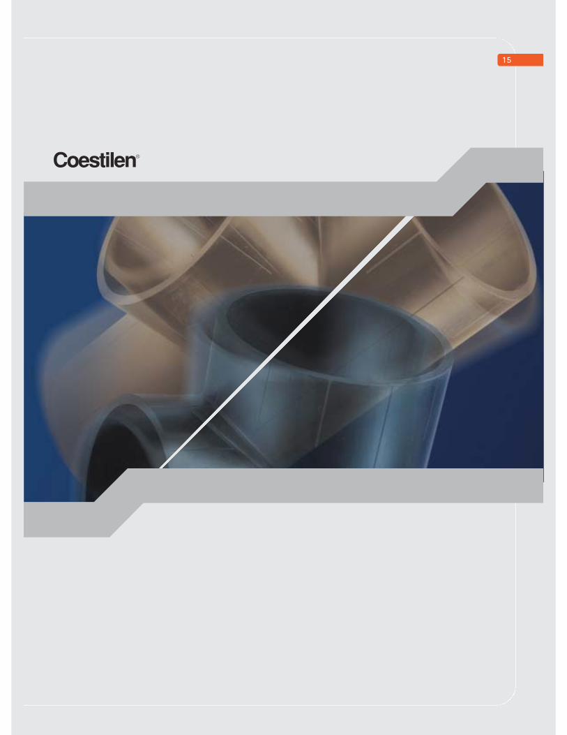
Coestilen®
16Coestilen
®
RAW MATERIAL NON-POLLUTANT
AND 100%RECYCLABLE
OUTSTANDING ELASTICITY ANDRESISTANCE TO MECHANICALSTRESS AND VIBRATIONS.IDEAL FOR SEISMIC AREAS
OUTSTANDING RESISTANCE TOWORKING TEMPERATURESBETWEEN –40° AND + 70°C, TOCHEMICALS AND THE EFFECTS OFTHE WEATHER
EXCELLENT RESISTANCE TOPRESSURE AND ACCIDENTPRESSURE SURGES
Coestilen® is the drainage system for welding made of polyethylenewhich is exceptionally elastic and resistant to mechanical stressand vibrations.
The programme consists of pipes and fittings in diam. of 32 to 315 mmand includes a wide range of joint fittings and connections to sanitaryand sewage systems.
The high molecular weight of PE is a guarantee against fracture due toprolonged use. It is also particularly suited to absorb mechanical stressesof significant intensity; specifically for installation in seismic areas.Moreover it offers excellent resistance to operating temperaturesbetween –40° and +70°C, with the capacity to handle peaksof up to 95°C.
Coestilen® pipes and fittings are compliant with UNI EN 1519.
17st
ress
in N
\mm
2 (k
g/ c
m2)
years
hours
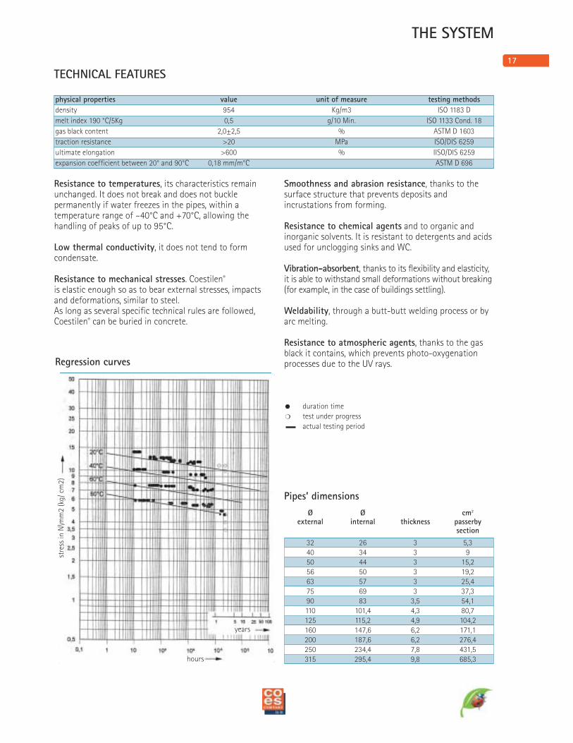
Regression curves
Resistance to temperatures, its characteristics remainunchanged. It does not break and does not bucklepermanently if water freezes in the pipes, within atemperature range of –40°C and +70°C, allowing thehandling of peaks of up to 95°C.
Low thermal conductivity, it does not tend to formcondensate.
Resistance to mechanical stresses. Coestilen®
is elastic enough so as to bear external stresses, impactsand deformations, similar to steel.As long as several specific technical rules are followed,Coestilen® can be buried in concrete.
Smoothness and abrasion resistance, thanks to thesurface structure that prevents deposits andincrustations from forming.
Resistance to chemical agents and to organic andinorganic solvents. It is resistant to detergents and acidsused for unclogging sinks and WC.
Vibration-absorbent, thanks to its flexibility and elasticity,it is able to withstand small deformations without breaking(for example, in the case of buildings settling).
Weldability, through a butt-butt welding process or byarc melting.
Resistance to atmospheric agents, thanks to the gasblack it contains, which prevents photo-oxygenationprocesses due to the UV rays.
Ø Ø cm2
external internal thickness passerbysection
32 26 3 5,340 34 3 950 44 3 15,256 50 3 19,263 57 3 25,475 69 3 37,390 83 3,5 54,1110 101,4 4,3 80,7125 115,2 4,9 104,2160 147,6 6,2 171,1200 187,6 6,2 276,4250 234,4 7,8 431,5315 295,4 9,8 685,3
TECHNICAL FEATURES
! duration time
� test under progress
actual testing period
Pipes’ dimensions
THE SYSTEM
physical properties value unit of measure testing methods
density 954 Kg/m3 ISO 1183 D
melt index 190 °C/5Kg 0,5 g/10 Min. ISO 1133 Cond. 18
gas black content 2,0±2,5 % ASTM D 1603
traction resistance >20 MPa ISO/DIS 6259
ultimate elongation >600 % IISO/DIS 6259
expansion coefficient between 20° and 90°C 0,18 mm/m°C ASTM D 696
18
b)
a)
CONNECTION
Coestilen® connection can be classified in 3 groups:
1) Fixed traction-resistant connections2) Connections not resistant to traction that can be
disassembled3) Traction-resistant connections that can be
disassembled
1) FIXED TRACTION-RESISTANTCONNECTIONS
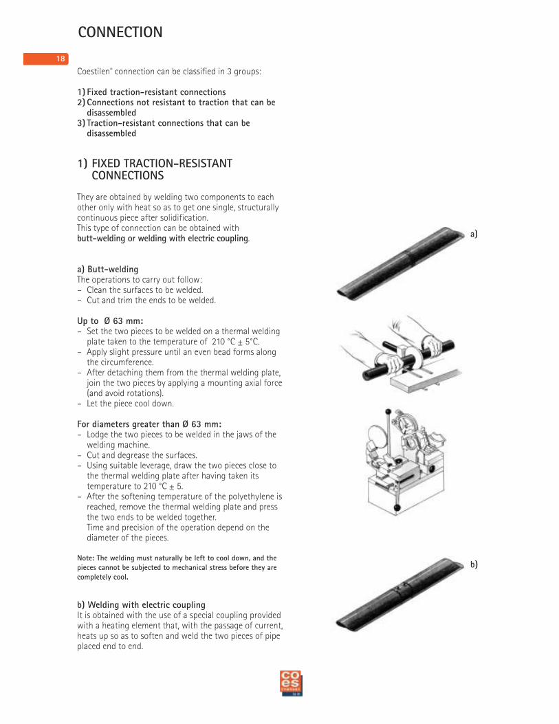
They are obtained by welding two components to eachother only with heat so as to get one single, structurallycontinuous piece after solidification.This type of connection can be obtained withbutt-welding or welding with electric coupling.
a) Butt-weldingThe operations to carry out follow:– Clean the surfaces to be welded.– Cut and trim the ends to be welded.
Up to Ø 63 mm:– Set the two pieces to be welded on a thermal welding
plate taken to the temperature of 210 °C ± 5°C.– Apply slight pressure until an even bead forms along
the circumference.– After detaching them from the thermal welding plate,
join the two pieces by applying a mounting axial force (and avoid rotations).
– Let the piece cool down.
For diameters greater than Ø 63 mm:– Lodge the two pieces to be welded in the jaws of the
welding machine.– Cut and degrease the surfaces.– Using suitable leverage, draw the two pieces close to
the thermal welding plate after having taken itstemperature to 210 °C ± 5.
– After the softening temperature of the polyethylene isreached, remove the thermal welding plate and pressthe two ends to be welded together.Time and precision of the operation depend on the diameter of the pieces.
Note: The welding must naturally be left to cool down, and the
pieces cannot be subjected to mechanical stress before they are
completely cool.
b) Welding with electric couplingIt is obtained with the use of a special coupling providedwith a heating element that, with the passage of current,heats up so as to soften and weld the two pieces of pipeplaced end to end.
19
2
1
4
3
1
2
3
4
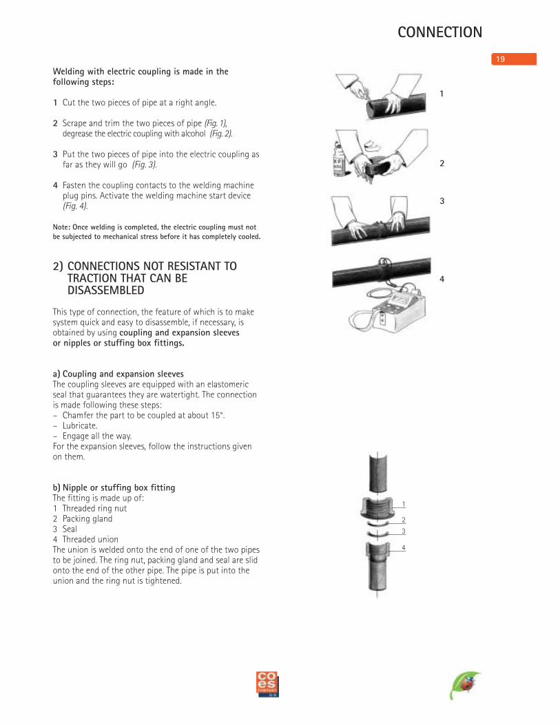
Welding with electric coupling is made in thefollowing steps:
1 Cut the two pieces of pipe at a right angle.
2 Scrape and trim the two pieces of pipe (Fig. 1),degrease the electric coupling with alcohol (Fig. 2).
3 Put the two pieces of pipe into the electric coupling as far as they will go (Fig. 3).
4 Fasten the coupling contacts to the welding machine plug pins. Activate the welding machine start device(Fig. 4).
Note: Once welding is completed, the electric coupling must not
be subjected to mechanical stress before it has completely cooled.
2) CONNECTIONS NOT RESISTANT TO TRACTION THAT CAN BEDISASSEMBLED
This type of connection, the feature of which is to makesystem quick and easy to disassemble, if necessary, isobtained by using coupling and expansion sleevesor nipples or stuffing box fittings.
a) Coupling and expansion sleevesThe coupling sleeves are equipped with an elastomericseal that guarantees they are watertight. The connectionis made following these steps:– Chamfer the part to be coupled at about 15°.– Lubricate.– Engage all the way.For the expansion sleeves, follow the instructions givenon them.
b) Nipple or stuffing box fittingThe fitting is made up of:1 Threaded ring nut2 Packing gland3 Seal4 Threaded unionThe union is welded onto the end of one of the two pipesto be joined. The ring nut, packing gland and seal are slidonto the end of the other pipe. The pipe is put into theunion and the ring nut is tightened.
CONNECTION
20
1
2
3
4
1
2
3
1
2
CONNECTION
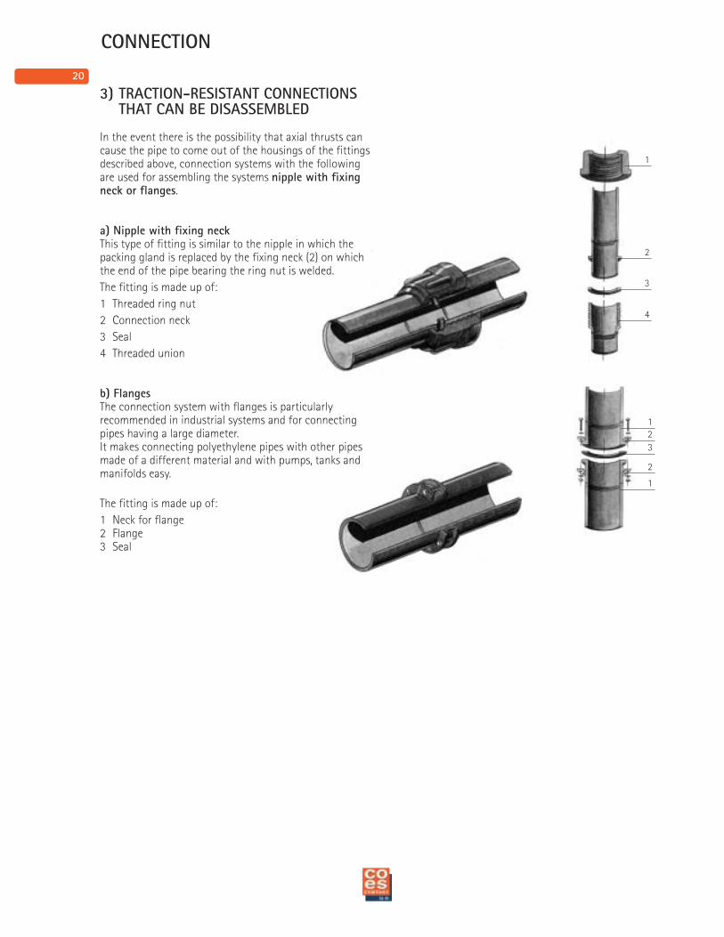
3) TRACTION-RESISTANT CONNECTIONS THAT CAN BE DISASSEMBLED
In the event there is the possibility that axial thrusts cancause the pipe to come out of the housings of the fittingsdescribed above, connection systems with the followingare used for assembling the systems nipple with fixingneck or flanges.
a) Nipple with fixing neckThis type of fitting is similar to the nipple in which thepacking gland is replaced by the fixing neck (2) on whichthe end of the pipe bearing the ring nut is welded.
The fitting is made up of:
1 Threaded ring nut
2 Connection neck
3 Seal
4 Threaded union
b) FlangesThe connection system with flanges is particularlyrecommended in industrial systems and for connectingpipes having a large diameter.It makes connecting polyethylene pipes with other pipesmade of a different material and with pumps, tanks andmanifolds easy.
The fitting is made up of:
1 Neck for flange2 Flange3 Seal
21
Length of the pipes in m
Changes of length ∆L in cm
INSTALLATION
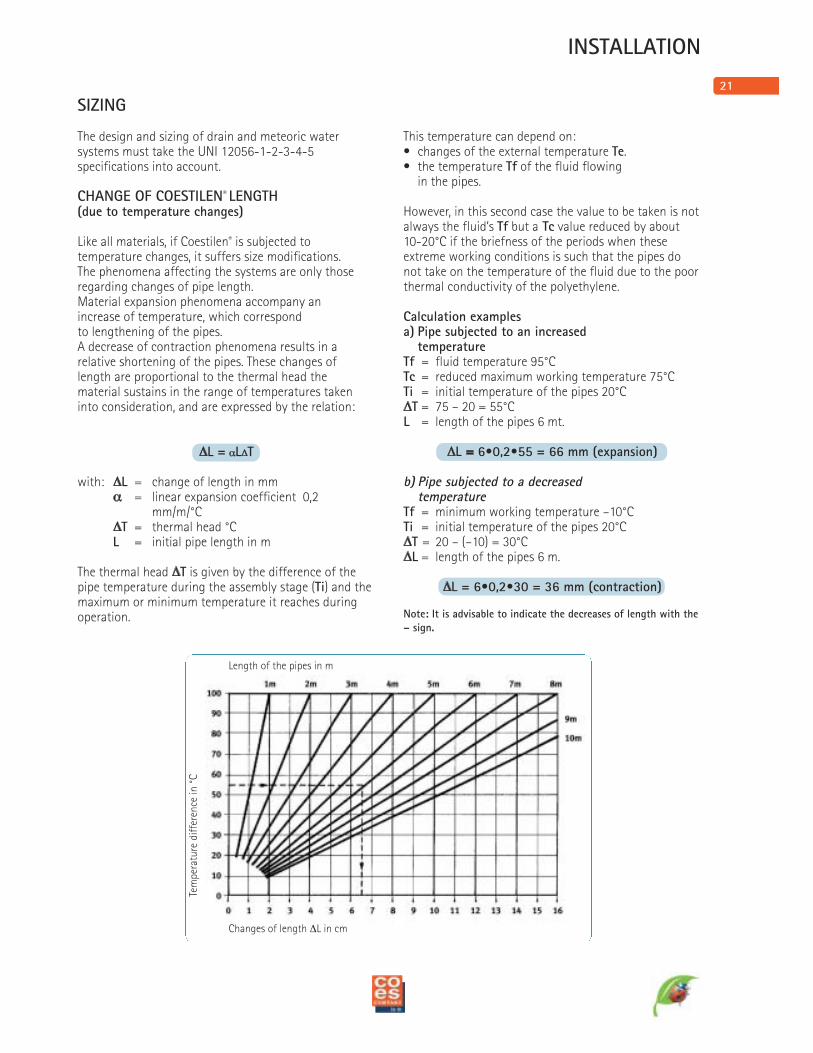
SIZING
The design and sizing of drain and meteoric watersystems must take the UNI 12056-1-2-3-4-5specifications into account.
CHANGE OF COESTILEN® LENGTH(due to temperature changes)
Like all materials, if Coestilen® is subjected totemperature changes, it suffers size modifications.The phenomena affecting the systems are only thoseregarding changes of pipe length.Material expansion phenomena accompany anincrease of temperature, which correspondto lengthening of the pipes.A decrease of contraction phenomena results in arelative shortening of the pipes. These changes oflength are proportional to the thermal head thematerial sustains in the range of temperatures takeninto consideration, and are expressed by the relation:
∆L = αL∆Twith: ∆L = change of length in mm
α = linear expansion coefficient 0,2 mm/m/°C
∆T = thermal head °CL = initial pipe length in m
The thermal head ∆T is given by the difference of thepipe temperature during the assembly stage (Ti) and themaximum or minimum temperature it reaches duringoperation.
This temperature can depend on:• changes of the external temperature Te.• the temperature Tf of the fluid flowing
in the pipes.
However, in this second case the value to be taken is notalways the fluid’s Tf but a Tc value reduced by about10-20°C if the briefness of the periods when theseextreme working conditions is such that the pipes donot take on the temperature of the fluid due to the poorthermal conductivity of the polyethylene.
Calculation examplesa) Pipe subjected to an increased
temperatureTf = fluid temperature 95°CTc = reduced maximum working temperature 75°CTi = initial temperature of the pipes 20°C∆T = 75 – 20 = 55°CL = length of the pipes 6 mt.
∆L = 6•0,2•55 = 66 mm (expansion)
b) Pipe subjected to a decreasedtemperature
Tf = minimum working temperature –10°CTi = initial temperature of the pipes 20°C∆T = 20 – (–10) = 30°C∆L = length of the pipes 6 m.
∆L = 6•0,2•30 = 36 mm (contraction)
Note: It is advisable to indicate the decreases of length with the
– sign.
Tem
pera
ture
dif
fere
nce
in °
C
22
∆L+ ∆L-
H
L
PF
PFPS
PS = Sliding point
PF = Fixed point
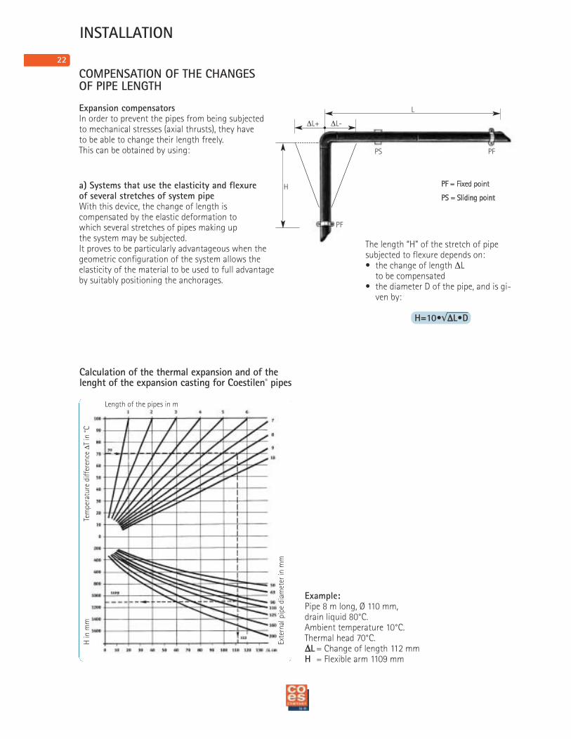
COMPENSATION OF THE CHANGESOF PIPE LENGTH
Expansion compensatorsIn order to prevent the pipes from being subjectedto mechanical stresses (axial thrusts), they haveto be able to change their length freely.This can be obtained by using:
a) Systems that use the elasticity and flexureof several stretches of system pipeWith this device, the change of length iscompensated by the elastic deformation towhich several stretches of pipes making upthe system may be subjected.It proves to be particularly advantageous when thegeometric configuration of the system allows theelasticity of the material to be used to full advantageby suitably positioning the anchorages.
INSTALLATION
Calculation of the thermal expansion and of the lenght of the expansion casting for Coestilen® pipes
Example:Pipe 8 m long, Ø 110 mm,drain liquid 80°C.Ambient temperature 10°C.Thermal head 70°C.∆L = Change of length 112 mmH = Flexible arm 1109 mm
The length “H” of the stretch of pipesubjected to flexure depends on:• the change of length ∆L
to be compensated• the diameter D of the pipe, and is gi-
ven by:
H=10•√∆L•D
Length of the pipes in m
Tem
pera
ture
dif
fere
nce
∆T in
°C
H in
mm
Exte
rnal
pip
e di
amet
er in
mm
23
∆L
∆L
PF PS PS
PS
PFPF
PS
15 Ø
15 Ø
X m
15 Ø
15 Ø
3 m
PF
PS
PS
PS
PF
PF
PS
PS
PS
Fig. A
∆L
PS = Sliding point
PF = Fixed point
L = length
∆L = change of length
PS = Sliding pointPF = Fixed point
INSTALLATION
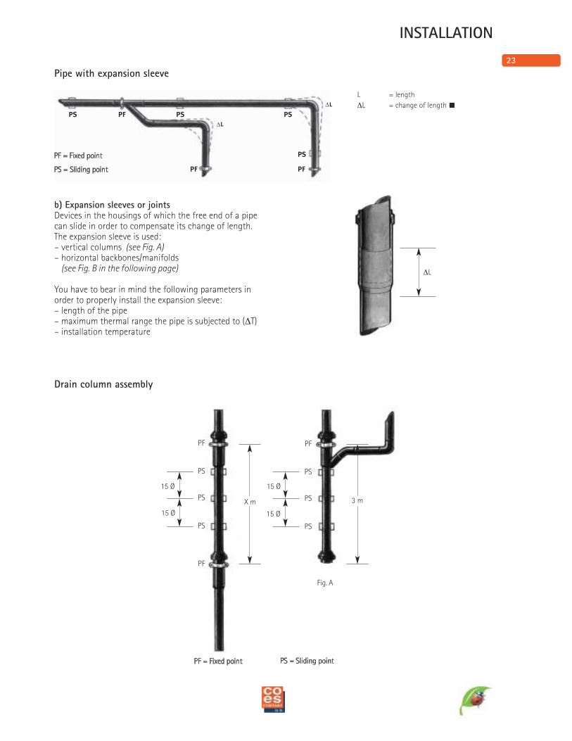
b) Expansion sleeves or jointsDevices in the housings of which the free end of a pipecan slide in order to compensate its change of length.The expansion sleeve is used:– vertical columns (see Fig. A)– horizontal backbones/manifolds
(see Fig. B in the following page)
You have to bear in mind the following parameters inorder to properly install the expansion sleeve:– length of the pipe– maximum thermal range the pipe is subjected to (∆T)– installation temperature
Drain column assembly
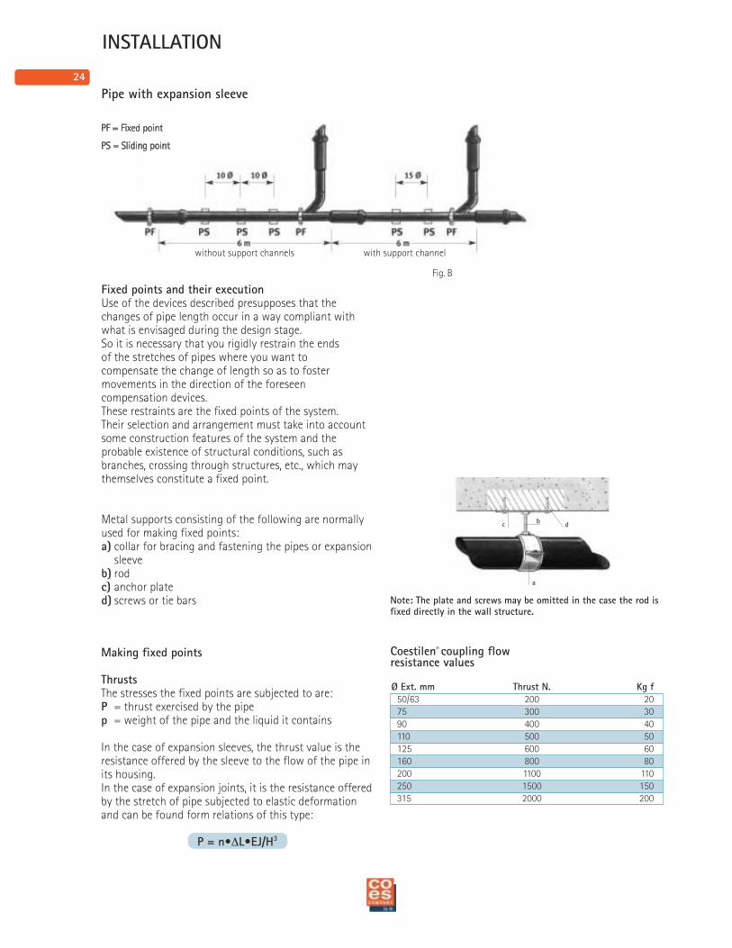
Pipe with expansion sleeve
24
cb
d
a
Fig. B
PS = Sliding point
PF = Fixed point
Coestilen® coupling flowresistance values
Ø Ext. mm Thrust N. Kg f
50/63 200 2075 300 3090 400 40110 500 50125 600 60160 800 80200 1100 110250 1500 150315 2000 200
Making fixed points
ThrustsThe stresses the fixed points are subjected to are:P = thrust exercised by the pipep = weight of the pipe and the liquid it contains
In the case of expansion sleeves, the thrust value is theresistance offered by the sleeve to the flow of the pipe inits housing.In the case of expansion joints, it is the resistance offeredby the stretch of pipe subjected to elastic deformationand can be found form relations of this type:
P = n•∆L•EJ/H3
INSTALLATION
Note: The plate and screws may be omitted in the case the rod isfixed directly in the wall structure.
Pipe with expansion sleeve
Fixed points and their executionUse of the devices described presupposes that thechanges of pipe length occur in a way compliant withwhat is envisaged during the design stage.So it is necessary that you rigidly restrain the endsof the stretches of pipes where you want tocompensate the change of length so as to fostermovements in the direction of the foreseencompensation devices.These restraints are the fixed points of the system.Their selection and arrangement must take into accountsome construction features of the system and theprobable existence of structural conditions, such asbranches, crossing through structures, etc., which maythemselves constitute a fixed point.
Metal supports consisting of the following are normallyused for making fixed points:a) collar for bracing and fastening the pipes or expansion
sleeveb) rodc) anchor plated) screws or tie bars
without support channels with support channel
25
INSTALLATION
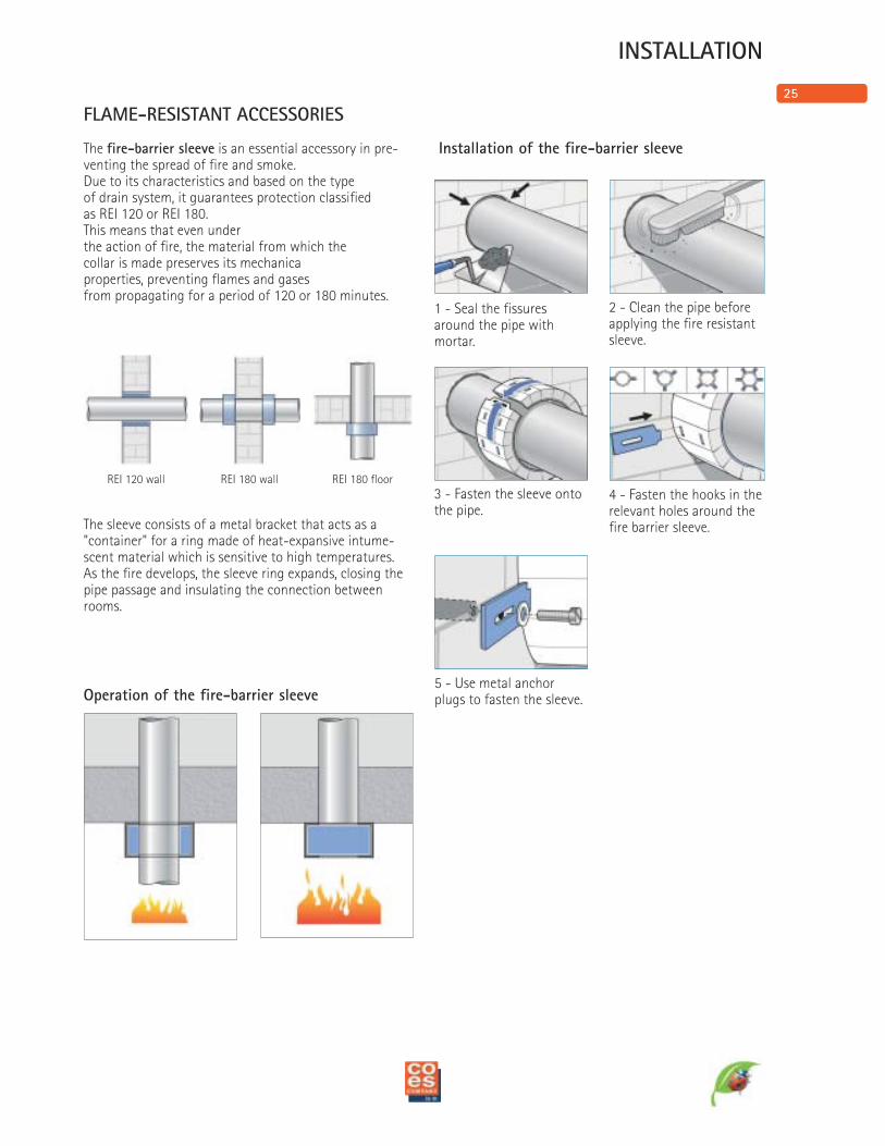
FLAME-RESISTANT ACCESSORIES
The fire-barrier sleeve is an essential accessory in pre-venting the spread of fire and smoke.Due to its characteristics and based on the typeof drain system, it guarantees protection classifiedas REI 120 or REI 180.This means that even underthe action of fire, the material from which thecollar is made preserves its mechanicaproperties, preventing flames and gasesfrom propagating for a period of 120 or 180 minutes.
The sleeve consists of a metal bracket that acts as a"container" for a ring made of heat-expansive intume-scent material which is sensitive to high temperatures.As the fire develops, the sleeve ring expands, closing thepipe passage and insulating the connection betweenrooms.
Operation of the fire-barrier sleeve
Installation of the fire-barrier sleeve
REI 120 wall REI 180 wall REI 180 floor
1 - Seal the fissuresaround the pipe withmortar.
2 - Clean the pipe beforeapplying the fire resistantsleeve.
3 - Fasten the sleeve ontothe pipe.
4 - Fasten the hooks in therelevant holes around thefire barrier sleeve.
5 - Use metal anchorplugs to fasten the sleeve.
26
FIELDS OF USE
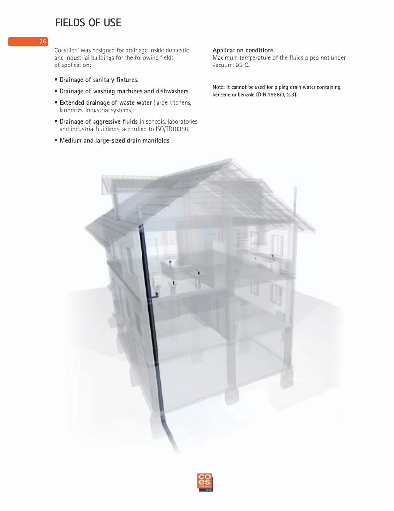
Coestilen® was designed for drainage inside domesticand industrial buildings for the following fieldsof application:
• Drainage of sanitary fixtures.
• Drainage of washing machines and dishwashers.
• Extended drainage of waste water (large kitchens,laundries, industrial systems).
• Drainage of aggressive fluids in schools, laboratoriesand industrial buildings, according to ISO/TR10358.
• Medium and large-sized drain manifolds.
Application conditionsMaximum temperature of the fluids piped not undervacuum: 95°C.
Note: It cannot be used for piping drain water containing
benzene or benzole (DIN 1986/3, 2.3).
27
TRANSPORT AND STORAGE
Fig. 3
Max 2 mtMax 2 years
Fig. 2
NO YES
Fig. 1
NO YES
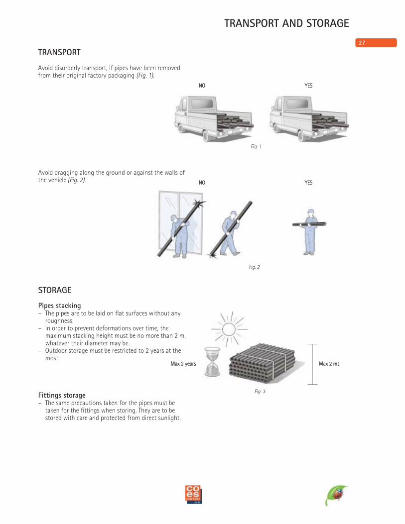
TRANSPORT
Avoid disorderly transport, if pipes have been removedfrom their original factory packaging (Fig. 1).
Avoid dragging along the ground or against the walls ofthe vehicle (Fig. 2).
STORAGE
Pipes stacking– The pipes are to be laid on flat surfaces without any
roughness.– In order to prevent deformations over time, the
maximum stacking height must be no more than 2 m,whatever their diameter may be.
– Outdoor storage must be restricted to 2 years at themost.
Fittings storage– The same precautions taken for the pipes must be
taken for the fittings when storing. They are to bestored with care and protected from direct sunlight.
28
Coestilen®
r
k
x1
d
x2
didA
s
L =5 m
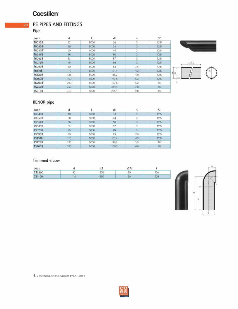
Pipe
code d L di s S*
T5032B 32 5000 26 3 12,5
T5040B 40 5000 34 3 12,5
T5050B 50 5000 44 3 12,5
T5056B 56 5000 50 3 12,5
T5063B 63 5000 57 3 12,5
T5075B 75 5000 69 3 12,5
T5090B 90 5000 83 3,5 12,5
T5110B 110 5000 101,4 4,3 12,5
T5125B 125 5000 115,2 4,9 12,5
T5160B 160 5000 147,6 6,2 12,5
T5200B 200 5000 187,6 6,2 16
T5250B 250 5000 234,4 7,8 16
T5315B 315 5000 295,4 9,8 16
BENOR pipe
code d L di s S*
T3040B 40 5000 34 3 12,5
T3050B 50 5000 44 3 12,5
T3056B 56 5000 50 3 12,5
T3063B 63 5000 57 3 12,5
T3075B 75 5000 69 3 12,5
T3090B 90 5000 83 3,5 12,5
T3110B 110 5000 101,4 4,3 12,5
T3125B 125 5000 117,2 3,9 16
T3160B 160 5000 150,2 4,9 16
Trimmed elbow
code d x1 x2/r k
CS0900 90 270 50 200
CS1100 110 300 60 220
PE PIPES AND FITTINGS
*S: Dimensional series envisaged by EN 1519-1
29
Coestilen®
k
x1
x2
d
r
d1
r
d
x
x
d
kx
x
k
d
x
k
x
k
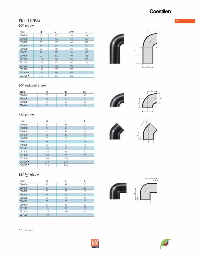
• Prefabricated
90° elbow
code d x1 x2/r k
C90300 32 100 30 70
C90400 40 150 30 100
C90500 50 180 40 125
C95600 56 210 40 150
C90600 63 210 50 140
C90700 75 210 70 125
C90900 90 240 90 135
C91100 110 270 100 155
C91200 125 200 110 75
C91600 160 140 140 -
C92000 200 200 200 -
C92500 • 250 335 335 -
C93100 • 315 370 370 -
90° reduced elbow
code d d1 x/r
CR0504 50 40 40
CR5605 56 50 40
CR0605 63 50 50
CR0656 63 56 50
45° elbow
code d x k
C40300 32 33 10
C40400 40 40 15
C40500 50 43 15
C45600 56 45 15
C40600 63 50 15
C40700 75 50 15
C40900 90 55 18
C41100 110 60 20
C41200 125 65 20
C41600 160 74 22
C42000 200 130 -
C42500 • 250 220 -
C43100 • 315 240 -
881/2° elbow
code d x k
C80300 32 43 20
C80400 40 50 20
C80500 50 60 20
C85600 56 65 20
C80600 63 70 20
C80700 75 75 20
C80900 90 80 20
C81100 110 95 25
C81200 125 100 25
C81600 160 - -
PE FITTINGS
30
Coestilen®
k3
x2
k2
x3
x1
k1
H
d1
d
Coestilen®
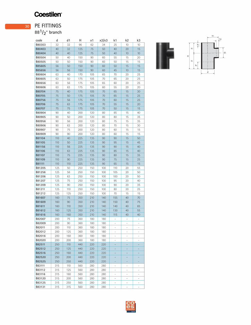
881/2° branch
code d d1 H x1 x2/x3 k1 k2 k3
B80303 32 32 96 62 34 25 10 10
B80403 40 32 125 75 50 40 20 15
B80404 40 40 125 75 50 40 10 10
B80504 50 40 150 90 60 55 15 20
B80505 50 50 150 90 60 50 15 15
B85605 56 50 150 90 60 50 15 15
B85656 56 56 150 90 60 45 10 15
B80604 63 40 170 105 65 70 20 25
B80605 63 50 175 105 70 65 20 25
B80656 63 56 175 105 65 60 20 25
B80606 63 63 175 105 60 55 20 20
B80704 75 40 175 105 70 65 15 30
B80705 75 50 175 105 70 65 15 25
B80756 75 56 175 105 70 60 15 25
B80706 75 63 175 105 70 55 15 20
B80707 75 75 175 105 70 50 15 15
B80904 90 40 200 120 80 85 15 40
B80905 90 50 200 120 80 80 15 35
B80956 90 56 200 120 80 75 15 35
B80906 90 63 200 120 80 70 15 30
B80907 90 75 200 120 80 60 15 15
B80909 90 90 200 120 80 60 15 15
B81104 110 40 225 135 90 90 15 50
B81105 110 50 225 135 90 95 15 45
B81156 110 56 225 135 90 90 15 40
B81106 110 63 225 135 90 85 15 40
B81107 110 75 225 135 90 80 15 35
B81109 110 90 225 135 90 75 15 25
B81111 110 110 225 135 90 65 15 15
B81205 125 50 250 150 100 110 20 55
B81256 125 56 250 150 100 105 20 50
B81206 125 63 250 150 100 100 20 50
B81207 125 75 250 150 100 95 20 40
B81209 125 90 250 150 100 90 20 35
B81211 125 110 250 150 100 80 20 25
B81212 125 125 250 150 100 70 15 15
B81607 160 75 350 210 140 155 40 70
B81609 160 90 350 210 140 150 40 75
B81611 160 110 350 210 140 140 40 65
B81612 160 125 350 210 140 130 40 55
B81616 160 160 350 210 140 115 40 40
B82007 200 75 360 180 180 - - -
B82009 200 90 360 180 180 - - -
B82011 200 110 360 180 180 - - -
B82012 200 125 360 180 180 - - -
B82016 200 160 360 180 180 - - -
B82020 200 200 360 180 180 - - -
B82511 250 110 440 220 220 - - -
B82512 250 125 440 220 220 - - -
B82516 250 160 440 220 220 - - -
B82520 250 200 440 220 220 - - -
B82525 250 250 440 220 220 - - -
B83111 315 110 560 280 280 - - -
B83112 315 125 560 280 280 - - -
B83116 315 160 560 280 280 - - -
B83120 315 200 560 280 280 - - -
B83125 315 250 560 280 280 - - -
B83131 315 315 560 280 280 - - -
PE FITTINGS
31
Coestilen®
d1
k2
k3
x3
x1
H
k1
d
x2
x1k1
d
30°
k2
x2
30°
d1
k3k2
k1
X2
X3
X1
H
d1
d
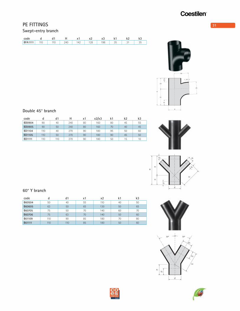
Double 45° branch
code d d1 H x1 x2/x3 k1 k2 k3
BD0904 90 40 240 80 160 80 45 55
BD0905 90 50 240 80 160 70 40 45
BD1104 110 40 270 90 180 95 50 60
BD1105 110 50 270 90 180 90 45 50
BD1111 110 110 270 90 180 50 15 10
60° Y branch
code d d1 x1 x2 k1 k3
B60504 50 40 55 110 40 50
B60605 63 50 65 130 50 65
B60705 75 50 70 140 60 70
B60706 75 63 70 140 50 60
B61109 110 90 85 180 70 80
B61111 110 110 85 180 50 60
Swept-entry branch
code d d1 H x1 x2 x3 k1 k2 k3BFA1111 110 110 240 142 128 198 35 31 35
PE FITTINGS
32
Coestilen®
d1
d
k1
k2
x2
k3
x3
H
x1
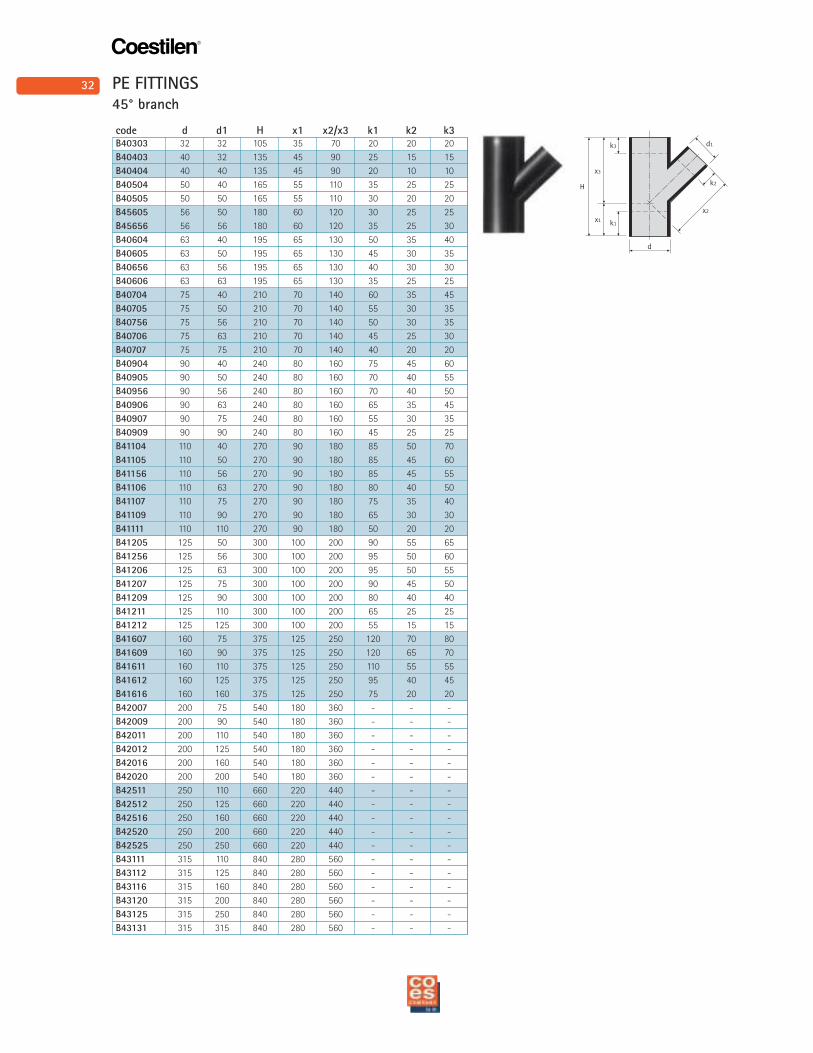
45° branch
code d d1 H x1 x2/x3 k1 k2 k3 B40303 32 32 105 35 70 20 20 20
B40403 40 32 135 45 90 25 15 15
B40404 40 40 135 45 90 20 10 10
B40504 50 40 165 55 110 35 25 25
B40505 50 50 165 55 110 30 20 20
B45605 56 50 180 60 120 30 25 25
B45656 56 56 180 60 120 35 25 30
B40604 63 40 195 65 130 50 35 40
B40605 63 50 195 65 130 45 30 35
B40656 63 56 195 65 130 40 30 30
B40606 63 63 195 65 130 35 25 25
B40704 75 40 210 70 140 60 35 45
B40705 75 50 210 70 140 55 30 35
B40756 75 56 210 70 140 50 30 35
B40706 75 63 210 70 140 45 25 30
B40707 75 75 210 70 140 40 20 20
B40904 90 40 240 80 160 75 45 60
B40905 90 50 240 80 160 70 40 55
B40956 90 56 240 80 160 70 40 50
B40906 90 63 240 80 160 65 35 45
B40907 90 75 240 80 160 55 30 35
B40909 90 90 240 80 160 45 25 25
B41104 110 40 270 90 180 85 50 70
B41105 110 50 270 90 180 85 45 60
B41156 110 56 270 90 180 85 45 55
B41106 110 63 270 90 180 80 40 50
B41107 110 75 270 90 180 75 35 40
B41109 110 90 270 90 180 65 30 30
B41111 110 110 270 90 180 50 20 20
B41205 125 50 300 100 200 90 55 65
B41256 125 56 300 100 200 95 50 60
B41206 125 63 300 100 200 95 50 55
B41207 125 75 300 100 200 90 45 50
B41209 125 90 300 100 200 80 40 40
B41211 125 110 300 100 200 65 25 25
B41212 125 125 300 100 200 55 15 15
B41607 160 75 375 125 250 120 70 80
B41609 160 90 375 125 250 120 65 70
B41611 160 110 375 125 250 110 55 55
B41612 160 125 375 125 250 95 40 45
B41616 160 160 375 125 250 75 20 20
B42007 200 75 540 180 360 - - -
B42009 200 90 540 180 360 - - -
B42011 200 110 540 180 360 - - -
B42012 200 125 540 180 360 - - -
B42016 200 160 540 180 360 - - -
B42020 200 200 540 180 360 - - -
B42511 250 110 660 220 440 - - -
B42512 250 125 660 220 440 - - -
B42516 250 160 660 220 440 - - -
B42520 250 200 660 220 440 - - -
B42525 250 250 660 220 440 - - -
B43111 315 110 840 280 560 - - -
B43112 315 125 840 280 560 - - -
B43116 315 160 840 280 560 - - -
B43120 315 200 840 280 560 - - -
B43125 315 250 840 280 560 - - -
B43131 315 315 840 280 560 - - -
PE FITTINGS
33
Coestilen®
k2
x3
881/2°
x1
H
x2
k1
k3
d1
d
k2
x3
881/2°
x1
H
x2
k1
k3
d1
d
k2
x3
x1
H
x2
k1
k3
d1
d
881/2°
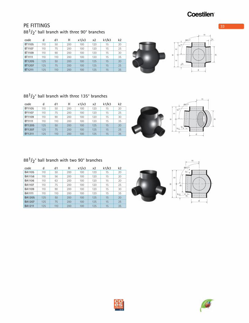
881/2° ball branch with three 90° branches
code d d1 H x1/x3 x2 k1/k3 k2
BT1105 110 50 200 100 120 15 20
BT1107 110 75 200 100 120 15 25
BT1109 110 90 200 100 120 15 30
BT1111 110 110 200 100 120 15 35
BT1205 125 50 200 100 125 15 20
BT1207 125 75 200 100 125 15 25
BT1211 125 110 200 100 125 15 35
881/2° ball branch with three 135° branches
code d d1 H x1/x3 x2 k1/k3 k2
BY1105 110 50 200 100 120 15 20
BY1107 110 75 200 100 120 15 25
BY1109 110 90 200 100 120 15 30
BY1111 110 110 200 100 120 15 35
BY1205 125 50 200 100 125 15 20
BY1207 125 75 200 100 125 15 25
BY1211 125 110 200 100 125 15 35
881/2° ball branch with two 90° branches
code d d1 H x1/x3 x2 k1/k3 k2BA1105 110 50 200 100 120 15 20
BA1156 110 56 200 100 120 15 20
BA1106 110 63 200 100 120 15 20
BA1107 110 75 200 100 120 15 25
BA1109 110 90 200 100 120 15 30
BA1111 110 110 200 100 120 15 35
BA1205 125 50 200 100 125 15 20
BA1207 125 75 200 100 125 15 25
BA1211 125 110 200 100 125 15 35
PE FITTINGS
34
Coestilen®
k2
x3
881/2°
x1
H
x2
k1
k3
d1
d
k2
x3
881/2°
x1
H
x2
k1
k3
d1
d
k2
x3
881/2°
x1
H
x2
k1
k3
d1
d
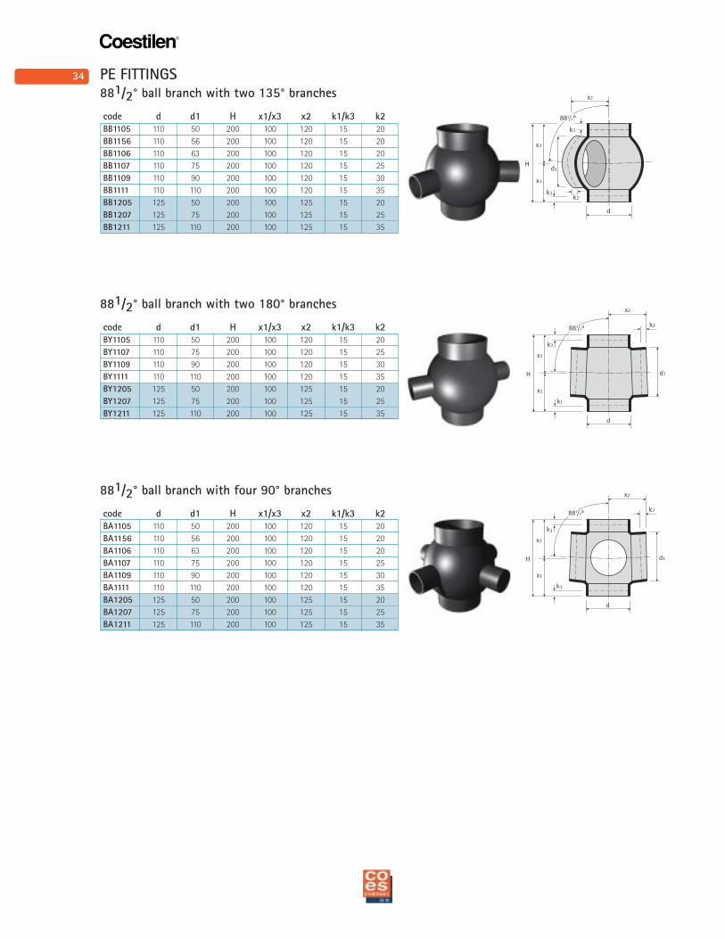
881/2° ball branch with two 135° branches
code d d1 H x1/x3 x2 k1/k3 k2
BB1105 110 50 200 100 120 15 20
BB1156 110 56 200 100 120 15 20
BB1106 110 63 200 100 120 15 20
BB1107 110 75 200 100 120 15 25
BB1109 110 90 200 100 120 15 30
BB1111 110 110 200 100 120 15 35
BB1205 125 50 200 100 125 15 20
BB1207 125 75 200 100 125 15 25
BB1211 125 110 200 100 125 15 35
881/2° ball branch with two 180° branches
code d d1 H x1/x3 x2 k1/k3 k2
BY1105 110 50 200 100 120 15 20
BY1107 110 75 200 100 120 15 25
BY1109 110 90 200 100 120 15 30
BY1111 110 110 200 100 120 15 35
BY1205 125 50 200 100 125 15 20
BY1207 125 75 200 100 125 15 25
BY1211 125 110 200 100 125 15 35
881/2° ball branch with four 90° branches
code d d1 H x1/x3 x2 k1/k3 k2
BA1105 110 50 200 100 120 15 20
BA1156 110 56 200 100 120 15 20
BA1106 110 63 200 100 120 15 20
BA1107 110 75 200 100 120 15 25
BA1109 110 90 200 100 120 15 30
BA1111 110 110 200 100 120 15 35
BA1205 125 50 200 100 125 15 20
BA1207 125 75 200 100 125 15 25
BA1211 125 110 200 100 125 15 35
PE FITTINGS
35
Coestilen®
d
k
A
x1
k
H
x2
d1
dA
x1
H
x2
d1
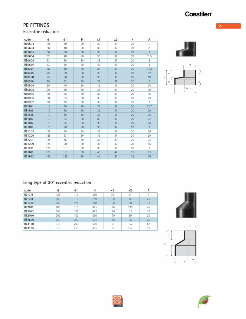
PE FITTINGSEccentric reduction
code d d1 H x1 x2 k A
RE0504 50 40 80 35 37 20 5
RE5604 56 40 80 35 37 20 8
RE5605 56 50 80 35 37 20 3
RE0604 63 40 80 35 37 20 11,5
RE0605 63 50 80 35 37 20 6
RE0656 63 56 80 35 37 20 3
RE0704 75 40 80 35 37 20 17,5
RE0705 75 50 80 35 37 20 12
RE0756 75 56 80 35 37 20 10
RE0706 75 63 80 35 37 20 6
RE0904 90 40 80 35 37 20 25
RE0905 90 50 80 35 37 20 20
RE0956 90 56 80 35 37 20 16
RE0906 90 63 80 35 37 20 13
RE0907 90 75 80 35 37 20 7
RE1104 110 40 80 35 37 20 33,7
RE1105 110 50 80 35 37 20 29
RE1156 110 56 80 35 37 20 26
RE1106 110 63 80 35 37 20 22
RE1107 110 75 80 35 37 20 16
RE1109 110 90 80 35 37 20 9
RE1205 125 50 80 35 37 20 36
RE1206 125 63 80 35 37 20 29
RE1207 125 75 80 35 37 20 23
RE1209 125 90 80 35 37 20 16
RE1211 125 110 80 35 37 20 7
RE1611 160 110 90 40 42 25 23
RE1612 160 125 90 40 42 25 16
Long type of 30° eccentric reduction
code d d1 H x1 x2 A
RL1211 125 110 160 70 64 7
RL1611 160 110 280 100 100 25
RL1612 160 125 240 100 80 17
RE2011 200 110 445 170 130 45
RE2012 200 125 415 170 115 37
RE2016 200 160 330 170 90 20
RE2520 250 200 405 158 157 25
RE3120 315 200 580 161 157 57
RE3125 315 250 435 161 157 32
36
Coestilen®
k1
H
x1
x3
k3
d
d1
A
x1
x2
H
d1
k
k
d
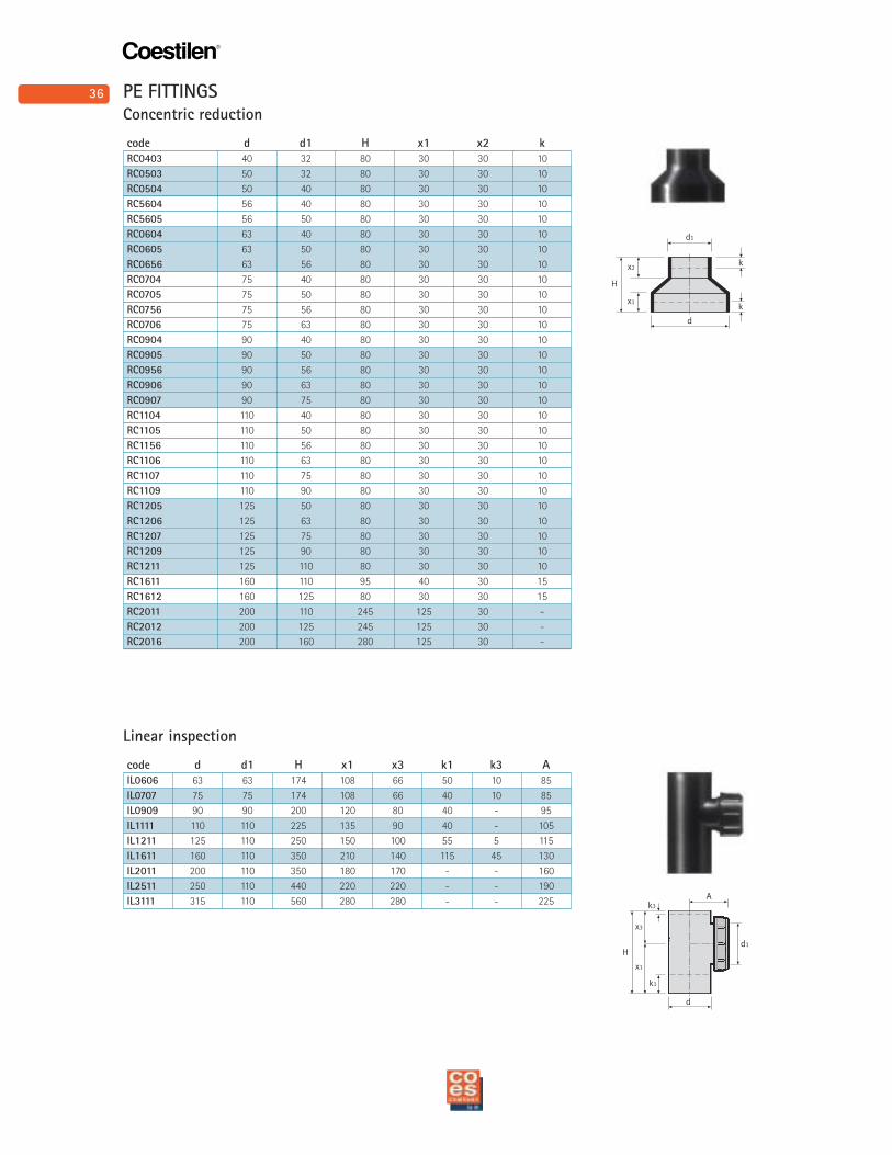
Concentric reduction
code d d1 H x1 x2 k
RC0403 40 32 80 30 30 10
RC0503 50 32 80 30 30 10
RC0504 50 40 80 30 30 10
RC5604 56 40 80 30 30 10
RC5605 56 50 80 30 30 10
RC0604 63 40 80 30 30 10
RC0605 63 50 80 30 30 10
RC0656 63 56 80 30 30 10
RC0704 75 40 80 30 30 10
RC0705 75 50 80 30 30 10
RC0756 75 56 80 30 30 10
RC0706 75 63 80 30 30 10
RC0904 90 40 80 30 30 10
RC0905 90 50 80 30 30 10
RC0956 90 56 80 30 30 10
RC0906 90 63 80 30 30 10
RC0907 90 75 80 30 30 10
RC1104 110 40 80 30 30 10
RC1105 110 50 80 30 30 10
RC1156 110 56 80 30 30 10
RC1106 110 63 80 30 30 10
RC1107 110 75 80 30 30 10
RC1109 110 90 80 30 30 10
RC1205 125 50 80 30 30 10
RC1206 125 63 80 30 30 10
RC1207 125 75 80 30 30 10
RC1209 125 90 80 30 30 10
RC1211 125 110 80 30 30 10
RC1611 160 110 95 40 30 15
RC1612 160 125 80 30 30 15
RC2011 200 110 245 125 30 -
RC2012 200 125 245 125 30 -
RC2016 200 160 280 125 30 -
Linear inspection
code d d1 H x1 x3 k1 k3 A
IL0606 63 63 174 108 66 50 10 85
IL0707 75 75 174 108 66 40 10 85
IL0909 90 90 200 120 80 40 - 95
IL1111 110 110 225 135 90 40 - 105
IL1211 125 110 250 150 100 55 5 115
IL1611 160 110 350 210 140 115 45 130
IL2011 200 110 350 180 170 - - 160
IL2511 250 110 440 220 220 - - 190
IL3111 315 110 560 280 280 - - 225
PE FITTINGS
37
Coestilen®
k
H
x1
x3
d
d1
A
a
32
1
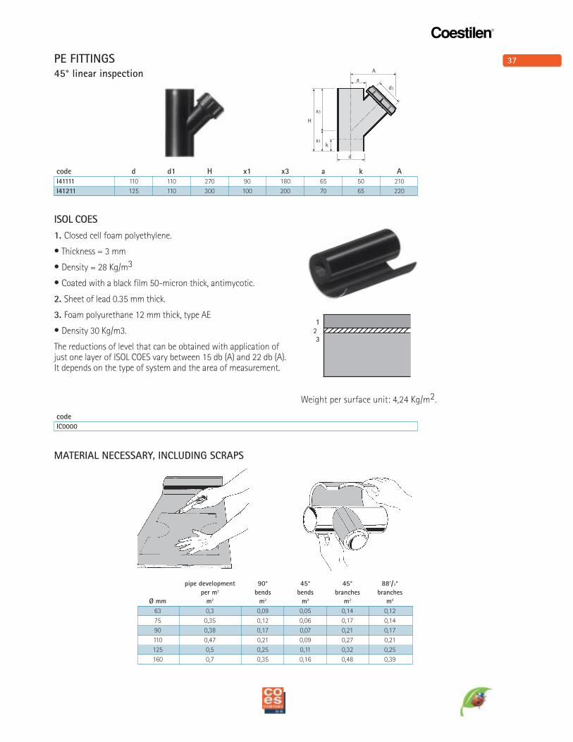
Weight per surface unit: 4,24 Kg/m2.
pipe development 90° 45° 45° 881/2°
per m2 bends bends branches branches
Ø mm m2 m2 m2 m2 m2
63 0,3 0,09 0,05 0,14 0,12
75 0,35 0,12 0,06 0,17 0,14
90 0,38 0,17 0,07 0,21 0,17
110 0,47 0,21 0,09 0,27 0,21
125 0,5 0,25 0,11 0,32 0,25
160 0,7 0,35 0,16 0,48 0,39
MATERIAL NECESSARY, INCLUDING SCRAPS
ISOL COES
1. Closed cell foam polyethylene.
• Thickness = 3 mm
• Density = 28 Kg/m3
• Coated with a black film 50-micron thick, antimycotic.
2. Sheet of lead 0.35 mm thick.
3. Foam polyurethane 12 mm thick, type AE
• Density 30 Kg/m3.
The reductions of level that can be obtained with application ofjust one layer of ISOL COES vary between 15 db (A) and 22 db (A).It depends on the type of system and the area of measurement.
45° linear inspection
code d d1 H x1 x3 a k A
I41111 110 110 270 90 180 65 50 210
I41211 125 110 300 100 200 70 65 220
code
IC0000
PE FITTINGS
38
Coestilen®
Hh
d
D
Hh
d
D
H
h
d
D
h
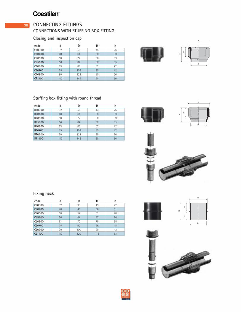
code d D H h
CF0300 32 56 45 26
CF0400 40 64 60 33
CF0500 50 72 60 33
CF5600 56 84 60 35
CF0600 63 86 62 42
CF0700 75 108 85 42
CF0900 90 124 85 50
CF1100 110 145 90 60
CONNECTIONS WITH STUFFING BOX FITTING
Closing and inspection cap
Stuffing box fitting with round thread
code d D H h
RF0300 32 56 43 26
RF0400 40 64 60 33
RF0500 50 72 60 33
RF5600 56 84 60 35
RF0600 63 86 62 42
RF0700 75 108 85 42
RF0900 90 124 85 50
RF1100 110 145 90 60
Fixing neck
code d D H h
CL0300 32 38 49 22
CL0400 40 46 66 31
CL0500 50 57 61 28
CL5600 56 64 57 26
CL0600 63 70 75 35
CL0700 75 90 96 45
CL0900 90 100 90 42
CL1100 110 120 113 53
CONNECTING FITTINGS
39
Coestilen®
H
d
D
s
E
D d1
m
s
k
D d1
s
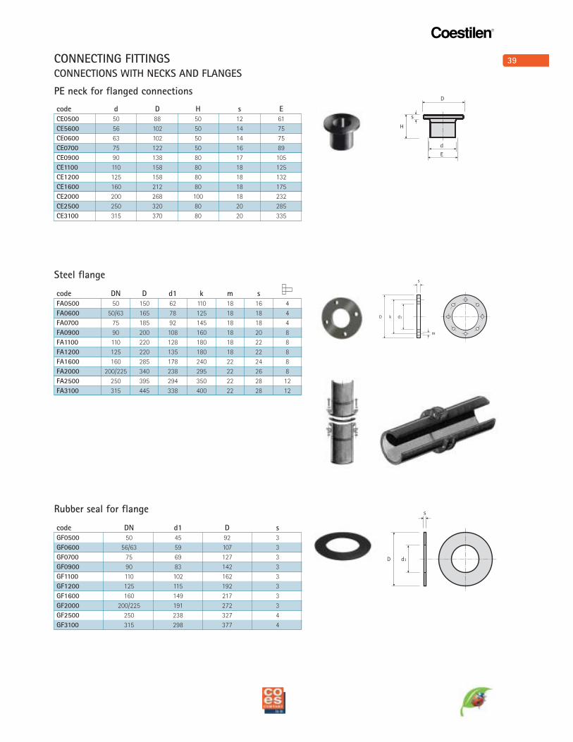
code d D H s E
CE0500 50 88 50 12 61
CE5600 56 102 50 14 75
CE0600 63 102 50 14 75
CE0700 75 122 50 16 89
CE0900 90 138 80 17 105
CE1100 110 158 80 18 125
CE1200 125 158 80 18 132
CE1600 160 212 80 18 175
CE2000 200 268 100 18 232
CE2500 250 320 80 20 285
CE3100 315 370 80 20 335
code DN D d1 k m s
FA0500 50 150 62 110 18 16 4
FA0600 50/63 165 78 125 18 18 4
FA0700 75 185 92 145 18 18 4
FA0900 90 200 108 160 18 20 8
FA1100 110 220 128 180 18 22 8
FA1200 125 220 135 180 18 22 8
FA1600 160 285 178 240 22 24 8
FA2000 200/225 340 238 295 22 26 8
FA2500 250 395 294 350 22 28 12
FA3100 315 445 338 400 22 28 12
code DN d1 D s
GF0500 50 45 92 3
GF0600 56/63 59 107 3
GF0700 75 69 127 3
GF0900 90 83 142 3
GF1100 110 102 162 3
GF1200 125 115 192 3
GF1600 160 149 217 3
GF2000 200/225 191 272 3
GF2500 250 238 327 4
GF3100 315 298 377 4
CONNECTIONS WITH NECKS AND FLANGES
PE neck for flanged connections
Steel flange
Rubber seal for flange
CONNECTING FITTINGS
40
Coestilen®
H
d
D
hk
15 ÷ 30°
0°
20°
H
d
D
h
15 ÷ 30°
H
d
d1
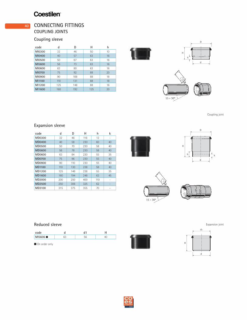
code d D H h
MI0300 32 46 50 10
MI0400 40 57 63 16
MI0500 50 67 63 16
MI5600 56 73 63 16
MI0600 63 80 63 16
MI0700 75 92 88 20
MI0900 90 108 88 18
MI1100 110 131 88 18
MI1200 125 148 88 16
MI1600 160 192 125 20
code d D H h k
MD0300 32 46 116 12 -
MD0400 40 58 230 60 40
MD0500 50 70 230 58 40
MD5600 56 78 230 58 40
MD0600 63 84 230 55 35
MD0700 75 96 230 55 40
MD0900 90 110 230 55 40
MD1100 110 130 238 58 40
MD1200 125 149 238 55 35
MD1600 160 194 248 63 45
MD2000 200 250 400 110 -
MD2500 250 306 325 62 -
MD3100 315 375 355 70 -
COUPLING JOINTS
Coupling sleeve
Expansion sleeve
code d d1 H
MI5606 � 63 56 40
Reduced sleeve
� On order only
CONNECTING FITTINGS
Expansion joint
Coupling joint
41
Coestilen®
H
d
D
h
d
h
H
d1
d
D
hH
d
d1
h1
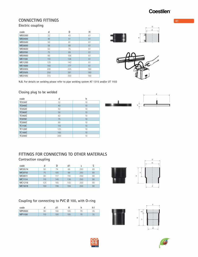
code d D H
ME0300 32 43 61
ME0400 40 51 61
ME0500 50 61 61
ME5600 56 68 61
ME0600 63 75 61
ME0700 75 89 61
ME0900 90 106 61
ME1100 110 126 61
ME1200 125 142 61
ME1600 160 177 61
ME2005 200 225 160
ME2505 250 281 160
ME3105 315 350 160
Electric coupling
code d h
TC030C 32 10
TC040C 40 10
TC050C 50 10
TC060C 56 10
TC060C 63 10
TC070C 75 10
TC090C 90 10
TC110C 110 10
TC120C 125 10
TC160C 160 10
TC200C 200 10
Closing plug to be welded
Contraction coupling
code d D d1 s S
MC0574 50 74 66 250 80
MC0710 75 105 99 250 80
MC0911 90 117 110 250 90
MC1114 110 145 136 250 90
MC1216 125 165 155 250 90
MC1619 160 196 184 250 90
Coupling for connecting to PVC Ø 100, with O-ring
code d d1 H h h1
MP0900 90 100 105 70 35
MP1100 110 100 105 70 35
CONNECTING FITTINGS
FITTINGS FOR CONNECTING TO OTHER MATERIALS
N.B. For details on welding please refer to pipe welding system AT 1315 and/or UT 1103
42
Coestilen®
H
d
D
h
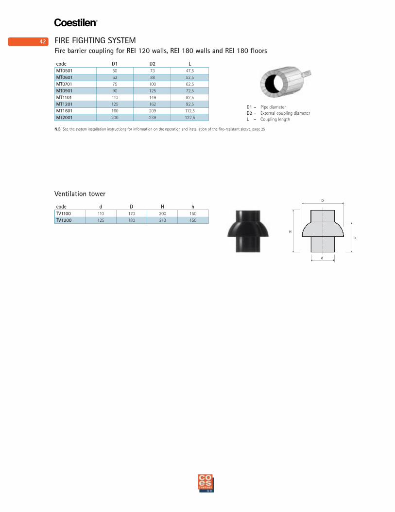
Ventilation tower
code D1 D2 L
MT0501 50 73 47,5
MT0601 63 88 52,5
MT0701 75 100 62,5
MT0901 90 125 72,5
MT1101 110 149 82,5
MT1201 125 162 92,5
MT1601 160 209 112,5
MT2001 200 239 122,5
code d D H h
TV1100 110 170 200 150
TV1200 125 180 210 150
N.B. See the system installation instructions for information on the operation and installation of the fire-resistant sleeve, page 25
D1 = Pipe diameter
D2 = External coupling diameter
L = Coupling length
Fire barrier coupling for REI 120 walls, REI 180 walls and REI 180 floors
FIRE FIGHTING SYSTEM
43
Coestilen®
k
di
H
x2
x1
d
h
H
di
d
D
hH
di
d
D
Art. GW1020
Art. GW1020
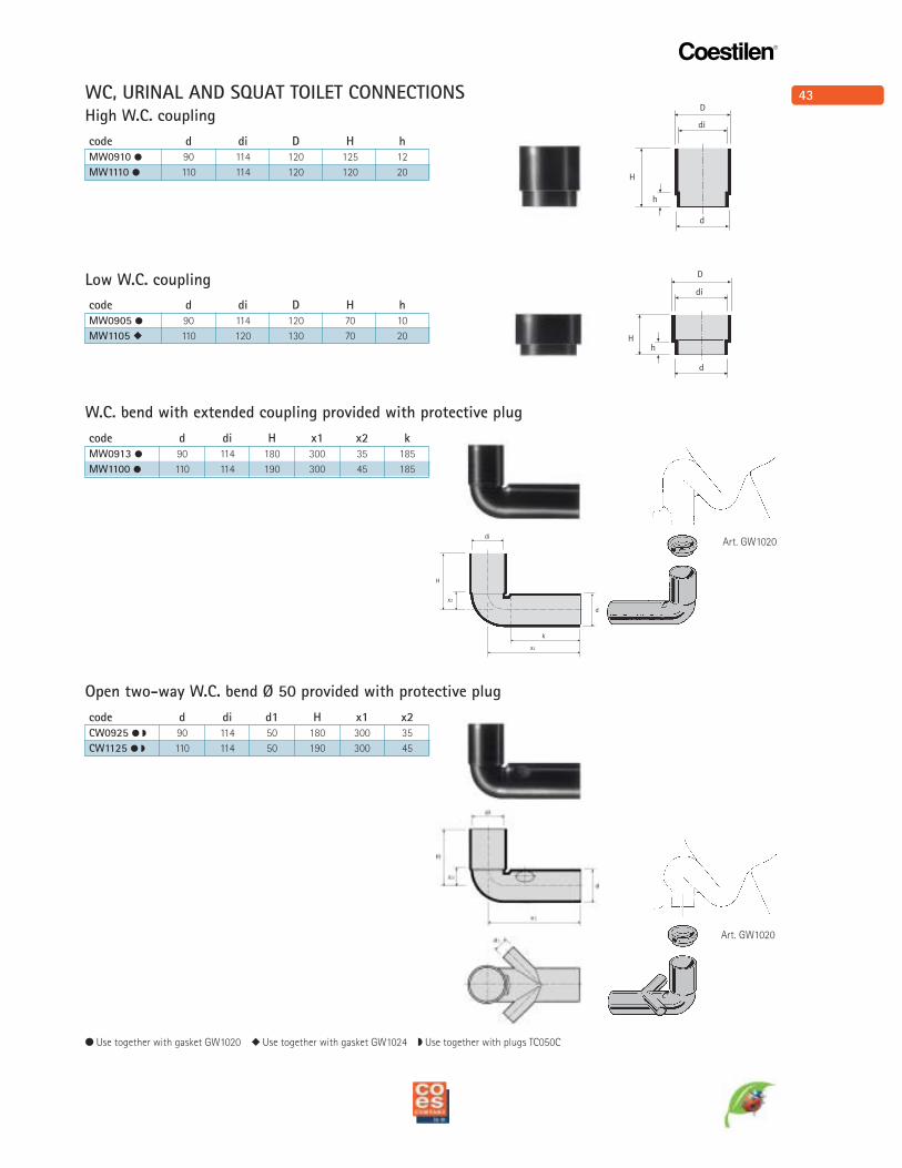
code d di D H h
MW0910 ! 90 114 120 125 12
MW1110 ! 110 114 120 120 20
High W.C. coupling
code d di D H h
MW0905 ! 90 114 120 70 10
MW1105 " 110 120 130 70 20
Low W.C. coupling
code d di H x1 x2 k
MW0913 ! 90 114 180 300 35 185
MW1100 ! 110 114 190 300 45 185
W.C. bend with extended coupling provided with protective plug
code d di d1 H x1 x2
CW0925 ! $ 90 114 50 180 300 35
CW1125 ! $ 110 114 50 190 300 45
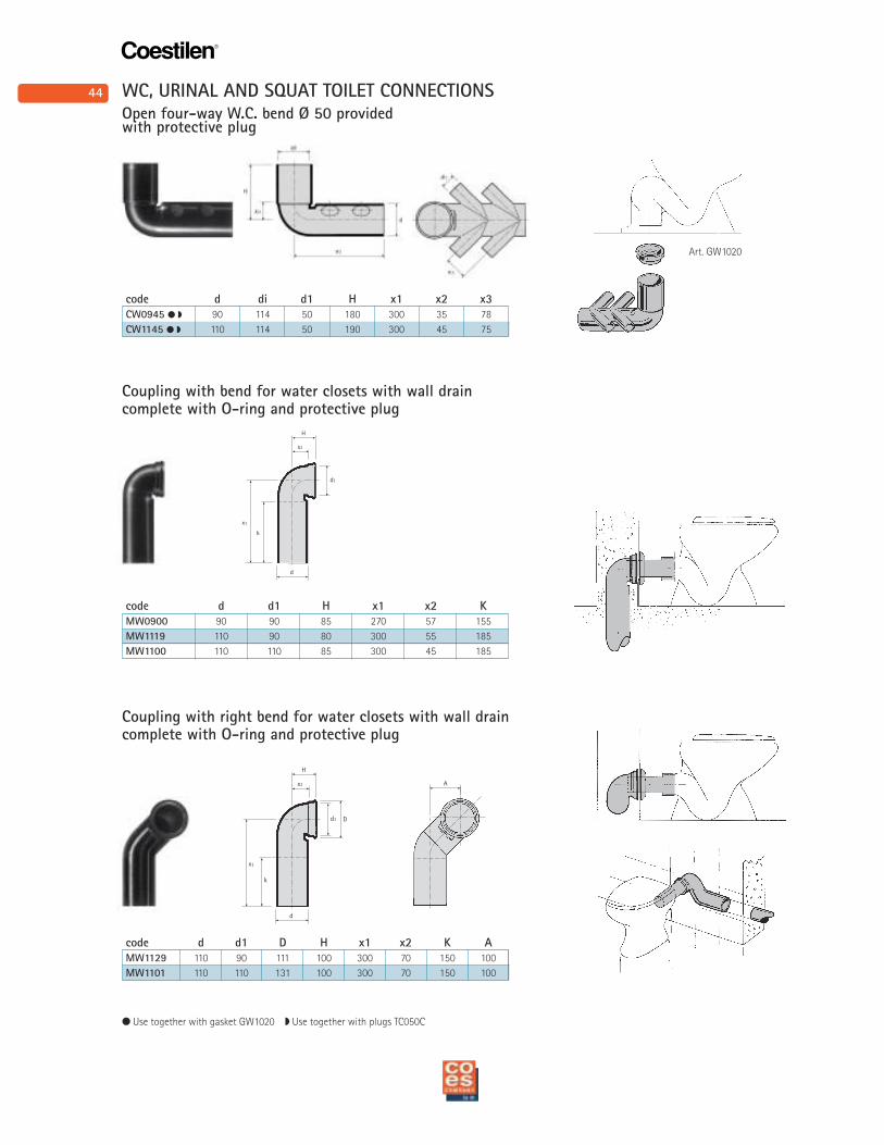
Open two-way W.C. bend Ø 50 provided with protective plug
! Use together with gasket GW1020 " Use together with gasket GW1024 $ Use together with plugs TC050C
WC, URINAL AND SQUAT TOILET CONNECTIONS
44
Coestilen®
x2
k
d
H
d1
x1
x2
k
d
H
d1
x1
D
A
Art. GW1020
! Use together with gasket GW1020 $ Use together with plugs TC050C
code d di d1 H x1 x2 x3
CW0945 ! $ 90 114 50 180 300 35 78
CW1145 ! $ 110 114 50 190 300 45 75
Open four-way W.C. bend Ø 50 provided with protective plug
Coupling with right bend for water closets with wall draincomplete with O-ring and protective plug
code d d1 H x1 x2 K
MW0900 90 90 85 270 57 155
MW1119 110 90 80 300 55 185
MW1100 110 110 85 300 45 185
Coupling with bend for water closets with wall draincomplete with O-ring and protective plug
code d d1 D H x1 x2 K A
MW1129 110 90 111 100 300 70 150 100
MW1101 110 110 131 100 300 70 150 100
WC, URINAL AND SQUAT TOILET CONNECTIONS
45
Coestilen®
x2
k
d
H
d1
x1
D
A
d1
H
x2
x1
d
x2
D
k
A
d1
H
x2
x1
d
x2
D
k
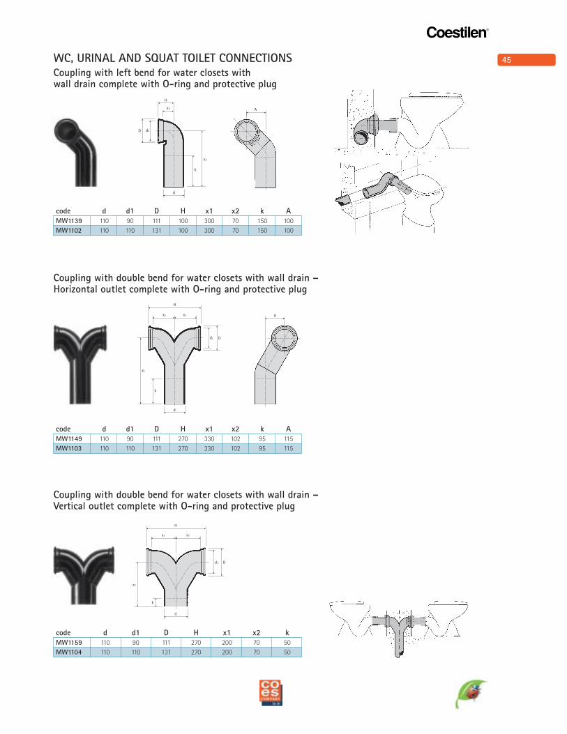
Coupling with left bend for water closets with wall drain complete with O-ring and protective plug
code d d1 D H x1 x2 k A
MW1139 110 90 111 100 300 70 150 100
MW1102 110 110 131 100 300 70 150 100
Coupling with double bend for water closets with wall drain –Horizontal outlet complete with O-ring and protective plug
code d d1 D H x1 x2 k A
MW1149 110 90 111 270 330 102 95 115
MW1103 110 110 131 270 330 102 95 115
Coupling with double bend for water closets with wall drain –Vertical outlet complete with O-ring and protective plug
WC, URINAL AND SQUAT TOILET CONNECTIONS
code d d1 D H x1 x2 k
MW1159 110 90 111 270 200 70 50
MW1104 110 110 131 270 200 70 50
46
Coestilen®
•
•
H
Ddi
h
d
d1
H
Dd
H
Dd
H
Ddi
h
d
code
C0400655
Pair of chromium plated washers and bold covers
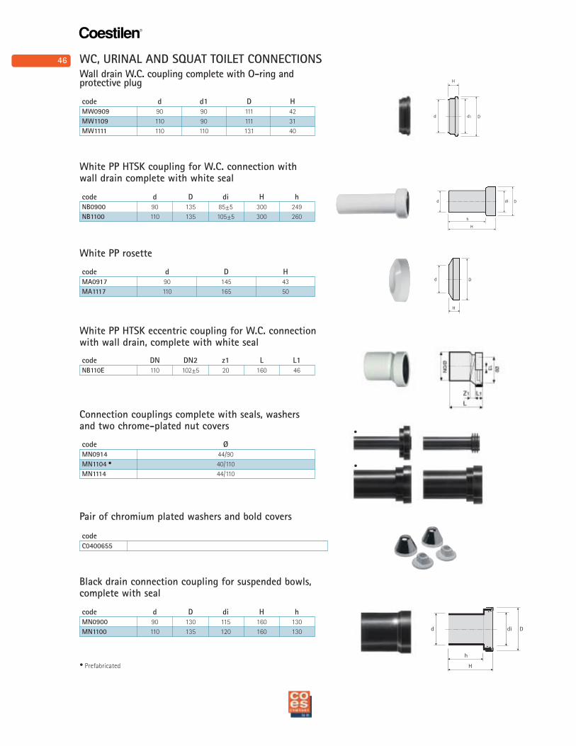
code d d1 D H
MW0909 90 90 111 42
MW1109 110 90 111 31
MW1111 110 110 131 40
Wall drain W.C. coupling complete with O-ring andprotective plug
White PP HTSK coupling for W.C. connection withwall drain complete with white seal
code Ø
MN0914 44/90
MN1104 • 40/110
MN1114 44/110
Connection couplings complete with seals, washersand two chrome-plated nut covers
code d D di H h
NB0900 90 135 85±5 300 249
NB1100 110 135 105±5 300 260
Black drain connection coupling for suspended bowls,complete with seal
code d D di H h
MN0900 90 130 115 160 130
MN1100 110 135 120 160 130
White PP rosette
code d D H
MA0917 90 145 43
MA1117 110 165 50
White PP HTSK eccentric coupling for W.C. connectionwith wall drain, complete with white seal
code DN DN2 z1 L L1
NB110E 110 102±5 20 160 46
• Prefabricated
WC, URINAL AND SQUAT TOILET CONNECTIONS
47
Coestilen®
H
Ddi
h
d
H
D
h
d
x
D
di
d
h1
hH
d1 d2
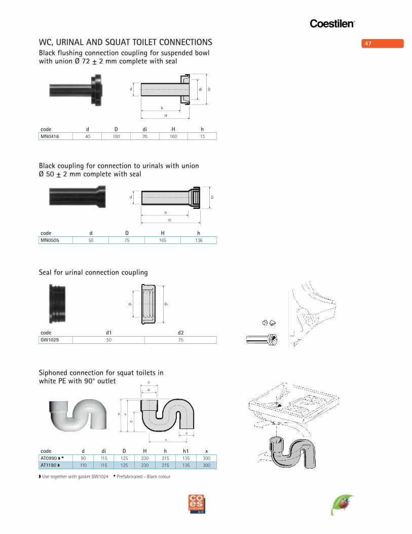
code d D di H h
MN0416 40 100 70 160 13
code d D H h
MN0505 50 75 165 136
code d1 d2
GW1029 50 75
code d di D H h h1 x
AT0990 $ • 90 115 125 230 215 135 300
AT1190 $ 110 115 125 230 215 135 300
Black flushing connection coupling for suspended bowl with union Ø 72 ± 2 mm complete with seal
Black coupling for connection to urinals with union Ø 50 ± 2 mm complete with seal
Seal for urinal connection coupling
Siphoned connection for squat toilets in white PE with 90° outlet
$ Use together with gasket GW1024 • Prefabricated - Black colour
WC, URINAL AND SQUAT TOILET CONNECTIONS
48
Coestilen®
d2
d1
d1
d2
d1
d1
d2
d2
d1
d1
d2
d1
x
D
di
h1
hH
d
code d di D H h h1 x
AT0945 $ • 90 115 125 230 210 150 320
AT1145 $ 110 115 125 230 210 150 320
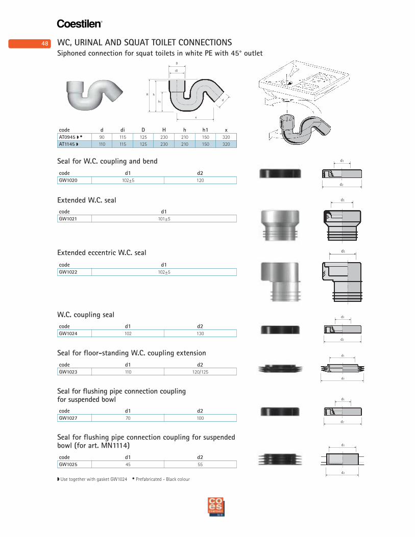
Siphoned connection for squat toilets in white PE with 45° outlet
Seal for W.C. coupling and bend
$ Use together with gasket GW1024 • Prefabricated - Black colour
code d1 d2
GW1020 102±5 120
W.C. coupling seal
code d1 d2
GW1024 102 130
Seal for floor-standing W.C. coupling extension
code d1 d2
GW1023 110 120/125
Seal for flushing pipe connection coupling for suspended bowl
code d1 d2
GW1027 70 100
Seal for flushing pipe connection coupling for suspendedbowl (for art. MN1114)
code d1 d2
GW1025 45 55
Extended W.C. seal
code d1
GW1021 101±5
Extended eccentric W.C. seal
code d1
GW1022 102±5
WC, URINAL AND SQUAT TOILET CONNECTIONS
49
Coestilen®
d
G
hH
x1
G
d
x2 H
H
Ddi
h
d
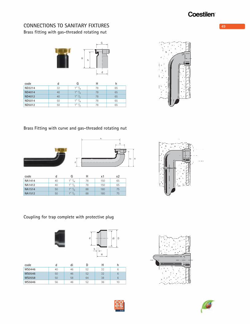
code d G H h
ND3214 32 1” 1/4 78 65
ND4014 40 1” 1/4 78 65
ND4012 40 1” 1/2 78 65
ND5014 50 1” 1/4 78 65
ND5012 50 1” 1/2 78 65
Brass fitting with gas-threaded rotating nut
code d G H x1 x2
NA1414 40 1” 1/4 78 150 65
NA1412 40 1” 1/2 78 150 65
NA1514 50 1” 1/4 88 180 75
NA1512 50 1” 1/2 88 180 75
Brass Fitting with curve and gas-threaded rotating nut
code d di D H h
MS0446 40 46 52 32 6
MS0546 50 46 52 32 6
MS0558 50 58 64 38 6
MS5646 56 46 52 36 10
Coupling for trap complete with protective plug
CONNECTIONS TO SANITARY FIXTURES
50
Coestilen®
d
di
x1
A
x2
did
H
h
D
dd1
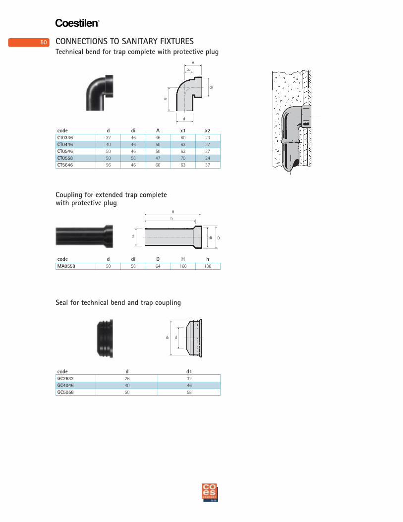
code d di A x1 x2
CT0346 32 46 46 60 23
CT0446 40 46 50 63 27
CT0546 50 46 50 63 27
CT0558 50 58 47 70 24
CT5646 56 46 60 63 37
Technical bend for trap complete with protective plug
code d d1
GC2632 26 32
GC4046 40 46
GC5058 50 58
Seal for technical bend and trap coupling
code d di D H h
MA0558 50 58 64 160 138
Coupling for extended trap complete with protective plug
CONNECTIONS TO SANITARY FIXTURES
51
Coestilen®
L1
L2
DN
1
L
L2
DN
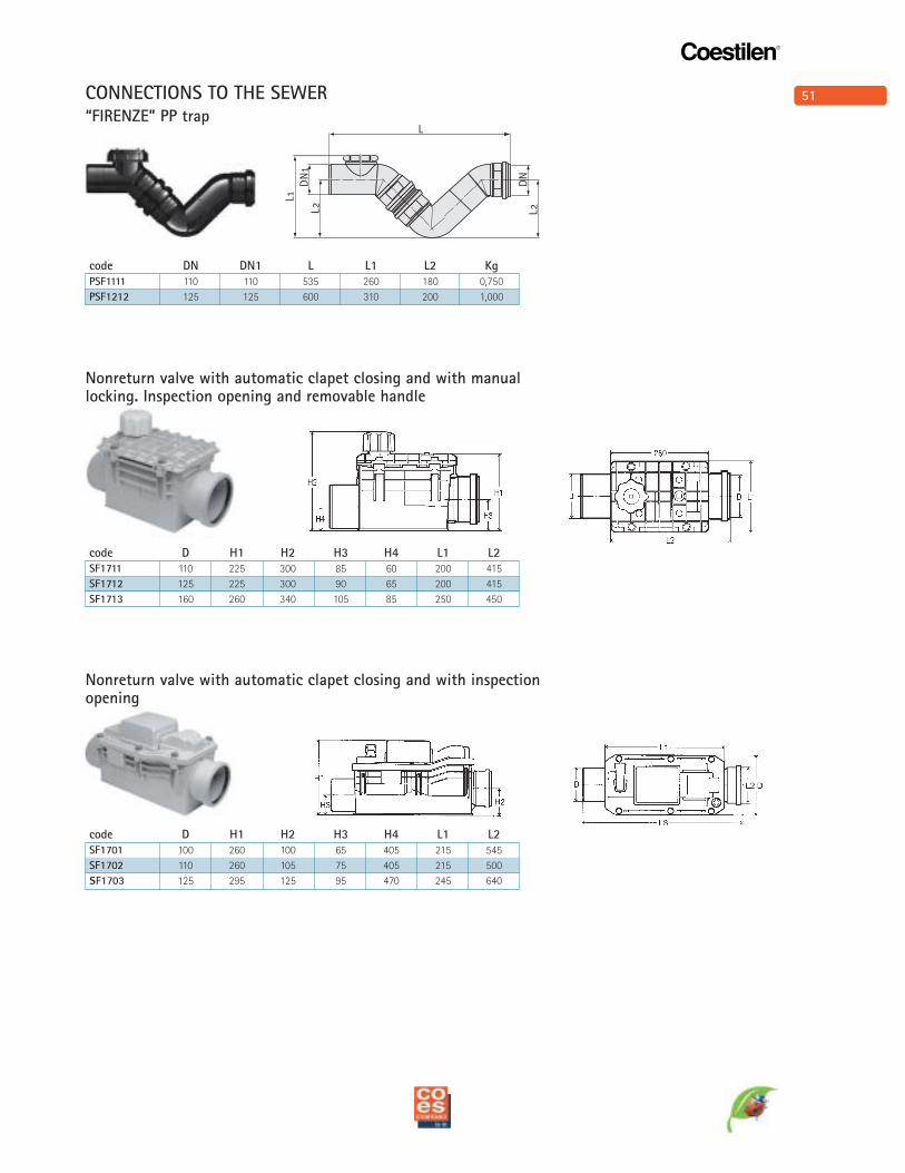
code DN DN1 L L1 L2 Kg
PSF1111 110 110 535 260 180 0,750
PSF1212 125 125 600 310 200 1,000
“FIRENZE” PP trap
code D H1 H2 H3 H4 L1 L2
SF1711 110 225 300 85 60 200 415
SF1712 125 225 300 90 65 200 415
SF1713 160 260 340 105 85 250 450
Nonreturn valve with automatic clapet closing and with manuallocking. Inspection opening and removable handle
code D H1 H2 H3 H4 L1 L2
SF1701 100 260 100 65 405 215 545
SF1702 110 260 105 75 405 215 500
SF1703 125 295 125 95 470 245 640
Nonreturn valve with automatic clapet closing and with inspectionopening
CONNECTIONS TO THE SEWER
52
Coestilen®
L
D
d
d
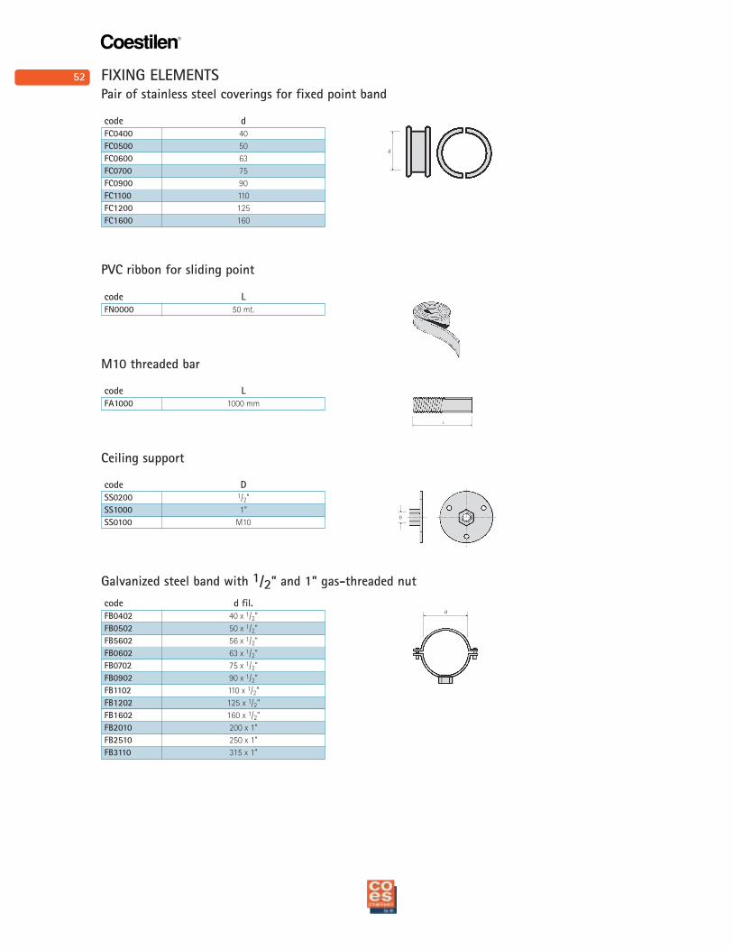
code d fil.
FB0402 40 x 1/2”
FB0502 50 x 1/2”
FB5602 56 x 1/2”
FB0602 63 x 1/2”
FB0702 75 x 1/2”
FB0902 90 x 1/2”
FB1102 110 x 1/2”
FB1202 125 x 1/2”
FB1602 160 x 1/2”
FB2010 200 x 1”
FB2510 250 x 1”
FB3110 315 x 1”
Galvanized steel band with 1/2” and 1” gas-threaded nut
code L
FN0000 50 mt.
PVC ribbon for sliding point
code L
FA1000 1000 mm
M10 threaded bar
code D
SS0200 1/2”
SS1000 1”
SS0100 M10
Ceiling support
code d
FC0400 40
FC0500 50
FC0600 63
FC0700 75
FC0900 90
FC1100 110
FC1200 125
FC1600 160
Pair of stainless steel coverings for fixed point band
FIXING ELEMENTS
53
Coestilen®
d
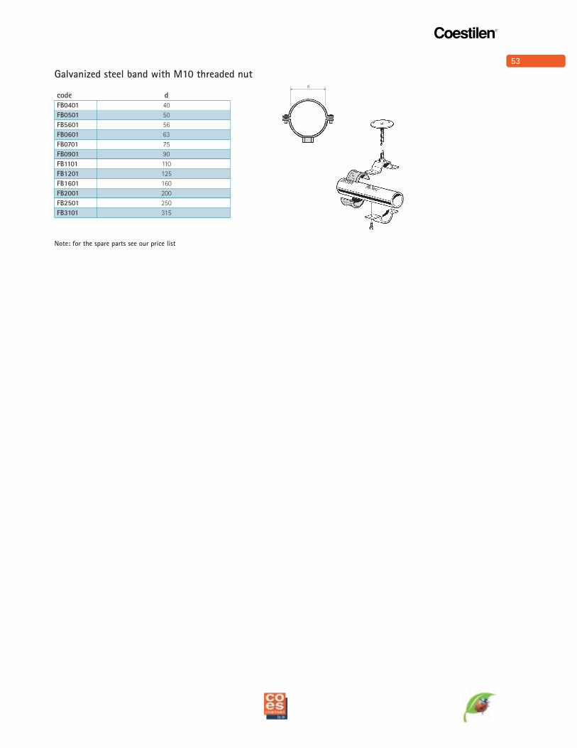
code d
FB0401 40
FB0501 50
FB5601 56
FB0601 63
FB0701 75
FB0901 90
FB1101 110
FB1201 125
FB1601 160
FB2001 200
FB2501 250
FB3101 315
Galvanized steel band with M10 threaded nut
Note: for the spare parts see our price list