Embed Size (px)
Citation preview
CommercialOil BurnerGuide
201CRD 301CRD
1050FFD 1150FFD
601CRD
701CRD 801CRD
702CRD

MODELS 201CRD& 301CRD
Advanced Oil Burners
Data sheet
2.5 to 5.5 GPH& 3.0 to 6.0 GPH
Carlin part number MN2301C Rev. 09/02/11© Copyright 2011 — Carlin Combustion Technology, Inc.
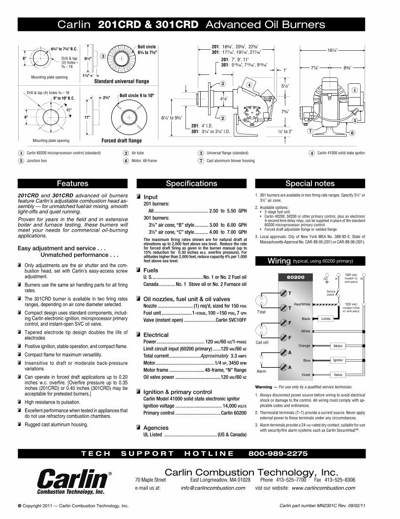
201CRD and 301CRD advanced oil burners feature Carlin’s adjustable combustion head as-sembly — for unmatched fuel/air mixing, smooth light-offs and quiet running.Proven for years in the field and in extensive boiler and furnace testing, these burners will meet your needs for commercial oil-burning applications.
Carlin 201CRD & 301CRD Advanced Oil Burners
Features Specifications
Input201 burners: All ........................................... 2.50 to 5.50 GPH301 burners: 3¼” air cone, “B” style ........... 3.00 to 6.00 GPH 3½” air cone, “C” style ........... 4.00 to 7.00 GPHThe maximum firing rates shown are for natural draft at elevations up to 2,000 feet above sea level. Reduce the rate for forced draft firing as given in the burner manual (up to 15% reduction for 0.30 inches w.c. overfire pressure). For altitudes higher than 2,000 feet, reduce capacity 4% per 1,000 feet above sea level.
Special notes
Wiring (typical, using 60200 primary)
Warning — For use only by a qualified service technician.
1. Always disconnect power source before wiring to avoid electrical shock or damage to the control. All wiring must comply with ap-plicable codes and ordinances.
2. Thermostat terminals (T–T) provide a current source. Never apply external power to these terminals under any circumstances.
3. Alarm terminals provide a 24 vac-rated dry contact, suitable for use with security/fire alarm systems such as Carlin SecureHeat™.
Easy adjustment and service . . . Unmatched performance . . .
Only adjustments are the air shutter and the com-bustion head, set with Carlin’s easy-access screw adjustment.
Burnersusethesameairhandlingpartsforallfiringrates.
The301CRDburner is available in two firing ratesranges, depending on air cone diameter selected.
Compact design uses standard components, includ-ing Carlin electronic ignition, microprocessor primary control, and instant-open SVC oil valve.
Tapered electrode tip design doubles the life of electrodes
Positiveignition,stableoperation,andcompactflame.
Compactflameformaximumversatility.
Insensitive to draft or moderate back-pressure variations.
Can operate in forced draft applications up to 0.20 inchesw.c. overfire. [Overfire pressure up to 0.35inches (201CRD) or 0.40 inches (301CRD) may be acceptable for pretested burners.]
High resistance to pulsation.
Excellentperformancewhentestedinappliancesthatdo not use refractory combustion chambers.
Rugged cast aluminum housing.
1. 301 burners are available in two firing rate ranges. Specify 3¼” or 3½” air cone.
2. Available options:• 2-stage fuel unit.• Carlin 40200, 50200 or other primary control, plus an electronic
4-second time delay relay, can be supplied in place of the standard 60200 microprocessor primary control.
• Forced draft adjustable flange or welded flange.
3. Local approvals: City of New York MEA No. 389-92-E; State of Massachusetts Approval No. CAR-88-05 (201) or CAR-88-06 (301).
FuelsU. S. ........................................No. 1 or No. 2 Fuel oilCanada .............No. 1 Stove oil or No. 2 Furnace oil
Oil nozzles, fuel unit & oil valvesNozzle ............................ (1) req’d, sized for 150 psig
Fuel unit ........................1-stage, 100 –150 psig, 7 gph Valve (instant open) .........................Carlin SVC10FF
ElectricalPower ...................................... 120 vac/60 hz/1-phase
Limit circuit input (60200 primary) ......120 vac/60 hz
Total current .........................Approximately 3.3 amps
Motor ...............................................1/4 hp, 3450 rpm
Motor frame ............................ 48-frame, “N” flangeOil valve power ....................................120 vac/60 hz
Ignition & primary controlCarlin Model 41000 solid state electronic ignitorIgnition voltage ..................................... 14,000 volts
Primary control ....................................Carlin 60200
AgenciesUL Listed .......................................... (US & Canada)
T e c h s u p p o r T h o T l i n e 800-989-2275
Carlin Combustion Technology, Inc.70 Maple Street East Longmeadow, MA 01028 Phone 413–525–7700 Fax 413–525–8306e-mail us at: [email protected] vist our website: www.carlincombustion.com
Instruction Manual
70 Maple Street East Longmeadow, MA 01028Ph 413-525-7700 Fx 413-525-8306
Carlin Combustion Technology, Inc.
Tech su p p ort 800-989-2275 carlincombustion.com
© Copyright 2011 — Carlin Combustion Technology, Inc.
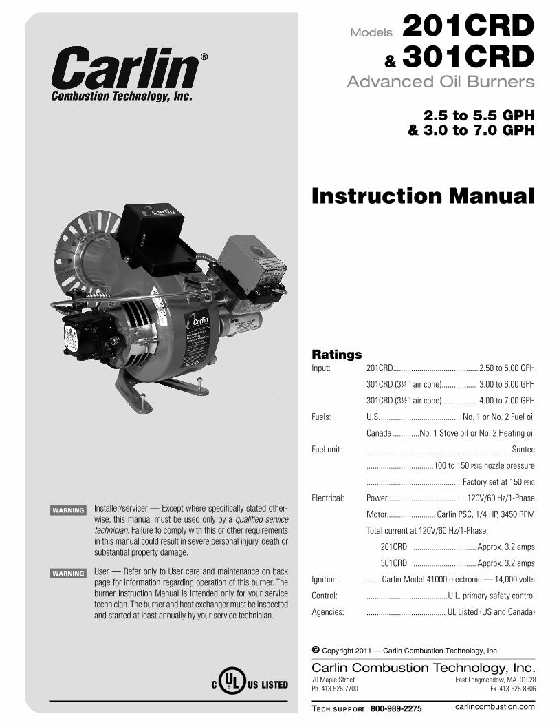
Installer/servicer — Except where specifically stated other-wise, this manual must be used only by a qualified service technician. Failure to comply with this or other requirements in this manual could result in severe personal injury, death or substantial property damage.
User — Refer only to User care and maintenance on back page for information regarding operation of this burner. The burner Instruction Manual is intended only for your service technician. The burner and heat exchanger must be inspected and started at least annually by your service technician.
RatingsInput: 201CRD.......................................... 2.50 to 5.00 GPH
301CRD (3¼’’ air cone) ................. 3.00 to 6.00 GPH
301CRD (3½’’ air cone) ................. 4.00 to 7.00 GPH
Fuels: U.S. ........................................No. 1 or No. 2 Fuel oil
Canada .............No. 1 Stove oil or No. 2 Heating oil
Fuel unit: ....................................................................... Suntec
.................................100 to 150 psig nozzle pressure
............................................... Factory set at 150 psig
Electrical: Power ...................................... 120V/60 Hz/1-Phase
Motor........................ Carlin PSC, 1/4 HP, 3450 RPM
Total current at 120V/60 Hz/1-Phase:
201CRD ............................... Approx. 3.2 amps
301CRD ............................... Approx. 3.2 amps
Ignition: ....... Carlin Model 41000 electronic — 14,000 volts
Control: ........................................U.L. primary safety control
Agencies: ....................................... UL Listed (US and Canada)
Models 201CRD& 301CRD
Advanced Oil Burners
2.5 to 5.5 GPH& 3.0 to 7.0 GPH
Carlin part number MN2301 Rev. 09/08/11– 2 –
Model 201CRD & 301CRD Advanced Oil Burners — Instruction Manual
Before installing or servicing . . .ContentsPLEASE read this first .............................................................2
General information ................................................................3
Codes and standards ..............................................................3
1. 201 & 301 Oil nozzles ........................................................3
2. Preparesite•assembleburner•mountburner ......4
3. Prepareburner .................................................................10
4. Wireburner•startburner–
40200 primary control .....................................................16
50200 primary control .....................................................18
60200 primary control .....................................................20
5. Adjustmentandverification .............................................22
6. Annualstart-upandservice ............................................23
7. Repair parts .....................................................................24
8. Maintenance/serviceprocedures ....................................26
Warranty ...............................................................................27
User care and maintenance .................................... Rearcover
PLEASE read this first . . .
Special attention flags . . .Please pay particular attention to the following when you see them through-out this manual.
Notifies you of hazards that WILL cause severe personal injury, death or substantial property damage.
Notifies you of hazards that CAN cause severe personal injury, death or substantial property damage.
Notifies you of hazards that WILL or CAN cause minor personal injury or property damage.
Notifies you of special instructions on installation, operation or maintenance that are important, but are not normally related to injury or property damage hazards.
When servicing the burner . . .• Disconnectelectricalsupplytoburnerbeforeattemptingtoserviceto
avoid electrical shock or possible injury from moving parts.
• Burner and appliance components can be extremely hot.Allow allparts to cool before attempting to handle or service to avoid potential of severe burns.
Installer/service technician — Train the user . . .• To properly operate the burner/appliance per this manual and the
appliance instructions. See User care and maintenance.
• Tokeepthismanualatorneartheburner/applianceforreadyaccessby the user and service technician.
• Tocontacttheservicetechnicianoroildealerifheencountersproblemswith the burner/appliance.
• Tokeeptheappliancespacefreeofflammableliquidsorvaporsandother combustible materials.
• Toneveruselaundryproducts,paints,varnishesorotherchemicalsinthe room occupied by the burner/appliance.
• To contact the service technician at least annually for startup andburner/appliance service.
Installer/service technician . . .
• Readallinstructionsbeforeproceeding.Performallprocedures,andin the order given to avoid potential of severe personal injury, death or substantial property damage.
• Beforeleavingthesiteafterstartuporservice,reviewtheUser care and maintenance page with the user. Make the user aware of all potential hazards and perform the training outlined below.
Should overheating occur:
(1) Shut off the oil supply to the burner.
(2) Donot shut off the control switch to the circulator or blower.
Follow the guidelines below to avoid potential severe personal injury, death or substantial property dam-age.
Carlin part number MN2301 Rev. 09/08/11 – 3 –
Model 201CRD & 301CRD Advanced Oil Burners — Instruction Manual
Codes and standards
Certification201CRDand301CRDburnersareU.L. listed for theU.S. andCanada,certifiedtocomplywithANSI/UL296, forusewith#1or#2heatingoil(perstandardASTMD396).
Burnerlabelslistcompliance,whenrequired,withspeciallocal,stateorprovincial approvals.
Install this burner in accordance with all local codes and authorities having jurisdiction. Regulations of these authori-ties take precedence over the general instructions provided in this manual.
United States installationsBurner/applianceinstallationsintheUnitedStatesmustcomplywiththelatest editions of NFPA 31 (Standard for the Installation of Oil-BurningEquipment),ANSI/NFPA70 (NationalElectricalCode),andallapplicablelocal codes.
Canadian installationsBurner/applianceinstallationsinCanadamustcomplywiththelatesteditionsofCSAB139(InstallationCodeforOilBurningEquipment),CSAstandardC22, Part 1 (Canadian Electrical Code), and all applicable local codes.
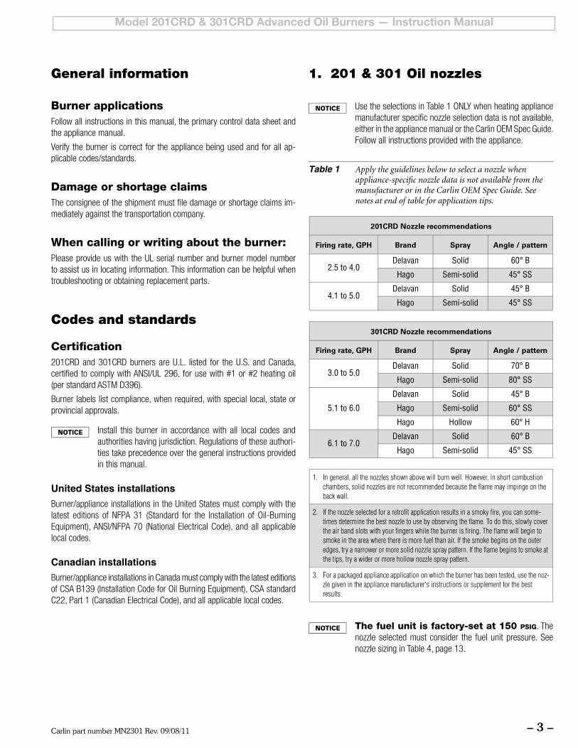
UsetheselectionsinTable1ONLYwhenheatingappliancemanufacturer specific nozzle selection data is not available, eitherintheappliancemanualortheCarlinOEMSpecGuide.Follow all instructions provided with the appliance.
Table 1 Apply the guidelines below to select a nozzle when appliance-specific nozzle data is not available from the manufacturer or in the Carlin OEM Spec Guide. See notes at end of table for application tips.
General information 1. 201 & 301 Oil nozzles
Burner applicationsFollow all instructions in this manual, the primary control data sheet and the appliance manual.
Verify the burner is correct for the appliance being used and for all ap-plicable codes/standards.
Damage or shortage claimsThe consignee of the shipment must file damage or shortage claims im-mediately against the transportation company.
When calling or writing about the burner:PleaseprovideuswiththeULserialnumberandburnermodelnumberto assist us in locating information. This information can be helpful when troubleshooting or obtaining replacement parts.
The fuel unit is factory-set at 150 psig. The nozzle selected must consider the fuel unit pressure. See nozzlesizinginTable4,page13.
Carlin part number MN2301 Rev. 09/08/11– 4 –
Model 201CRD & 301CRD Advanced Oil Burners — Instruction Manual
2. Prepare site • assemble burner • mount burner
Vent system
General
Donotinstallthisburnerunlessyouhaveverifiedtheentire vent system and the appliance are in good condi-tion and comply with all applicable codes.
• Theventandchimneymustbesizedandconstructedin accordance with all applicable codes.
• Donotinstalloruseanexistingmanualdamperinthe breeching (vent connector) or chimney.
• Donotconnect theapplianceventconnector toachimney or vent serving a fireplace, incinerator or solid-fuel-burning apparatus.
• Inacoldclimate,donotventintoamasonrychimneythat has one or more sides exposed to the outside. Youmustinstallalistedstainlesssteel linerinthechimneytoventtheflueproducts.
• Adefectiveventsystemcouldresultinseverepersonalinjury, death or substantial property damage.
Prepare vent/chimney• Secureallmetalventjointswithscrews,followingtheventmanufac-
turer’s instructions.
• Sealalljointsintheventsystemandchimney.
• Repair masonry chimney lining and repair all mortar joints asneeded.
• Installabarometricdraftregulatorintheventpipingifspecifiedintheappliance manual. (The damper must be located in the same space as the appliance.)
• Providesupportfortheventpiping.Donotresttheweightofanyoftheventpipingontheapplianceflueoutlet.
Combustion and ventilation air openings
GeneralCheck appliance manual and applicable codes for required sizing, designandplacementofcombustion/ventilationairopenings.Youcanusethefollowinggeneralguidelines,takenfromNFPA31,providedthey meet all local requirements.
Free area — Louvers and screens• Air opening sizes are alwaysgiven in free area.Thismeansafter
deduction for louver obstruction. If you can’t find the louver reduction for the grilles used, assume free area is 20% of total for wood louvers, or60%oftotalformetallouvers.
• Screenscanbenofinerthan¼-inchmesh,andmustbeaccessiblefor cleaning.
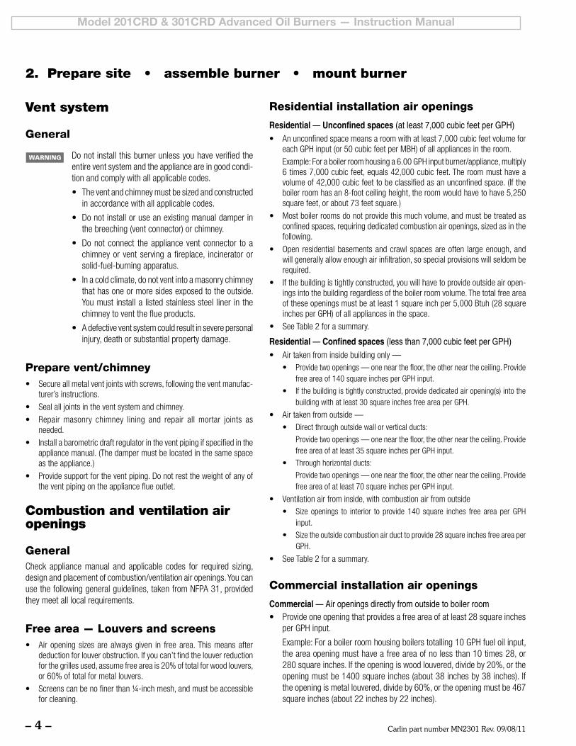
Residential installation air openings
Residential — Unconfined spaces (at least 7,000 cubic feet per GPH)• Anunconfinedspacemeansaroomwithatleast7,000cubicfeetvolumefor
eachGPHinput(or50cubicfeetperMBH)ofallappliancesintheroom.
Example:Foraboilerroomhousinga6.00GPHinputburner/appliance,multiply6times7,000cubicfeet,equals42,000cubicfeet.Theroommusthaveavolume of 42,000 cubic feet to be classified as an unconfined space. (If the boilerroomhasan8-footceilingheight,theroomwouldhavetohave5,250squarefeet,orabout73feetsquare.)
• Mostboilerroomsdonotprovidethismuchvolume,andmustbetreatedasconfined spaces, requiring dedicated combustion air openings, sized as in the following.
• Open residentialbasementsandcrawlspacesareoften largeenough,andwill generally allow enough air infiltration, so special provisions will seldom be required.
• Ifthebuildingistightlyconstructed,youwillhavetoprovideoutsideairopen-ings into the building regardless of the boiler room volume. The total free area oftheseopeningsmustbeatleast1squareinchper5,000Btuh(28squareinchesperGPH)ofallappliancesinthespace.
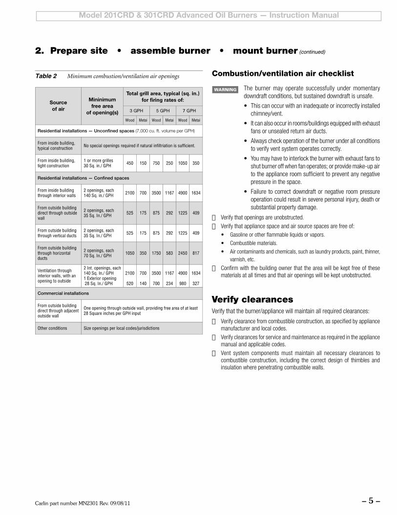
• SeeTable2forasummary.
Residential — Confined spaces (less than 7,000 cubic feet per GPH)• Airtakenfrominsidebuildingonly—
• Providetwoopenings—onenearthefloor,theotherneartheceiling.Providefreeareaof140squareinchesperGPHinput.
• Ifthebuildingistightlyconstructed,providededicatedairopening(s)intothebuildingwithatleast30squareinchesfreeareaperGPH.
• Airtakenfromoutside—• Directthroughoutsidewallorverticalducts:
Providetwoopenings—onenearthefloor,theotherneartheceiling.Providefreeareaofatleast35squareinchesperGPHinput.
• Throughhorizontalducts:
Providetwoopenings—onenearthefloor,theotherneartheceiling.Providefreeareaofatleast70squareinchesperGPHinput.
• Ventilationairfrominside,withcombustionairfromoutside• Size openings to interior to provide140 square inches free area per GPH
input.
• Sizetheoutsidecombustionairducttoprovide28squareinchesfreeareaperGPH.
• SeeTable2forasummary.
Commercial installation air openings
Commercial — Air openings directly from outside to boiler room• Provideoneopeningthatprovidesafreeareaofatleast28squareinches
perGPHinput.
Example:Foraboilerroomhousingboilerstotalling10GPHfueloilinput,the area opening must have a free area of no less than 10 times 28, or 280 square inches. If the opening is wood louvered, divide by 20%, or the openingmustbe1400squareinches(about38inchesby38inches).Iftheopeningismetallouvered,divideby60%,ortheopeningmustbe467square inches (about 22 inches by 22 inches).
Carlin part number MN2301 Rev. 09/08/11 – 5 –
Model 201CRD & 301CRD Advanced Oil Burners — Instruction Manual
Combustion/ventilation air checklist
The burner may operate successfully under momentary downdraft conditions, but sustained downdraft is unsafe.
• Thiscanoccurwithaninadequateorincorrectlyinstalledchimney/vent.
• Itcanalsooccurinrooms/buildingsequippedwithexhaustfans or unsealed return air ducts.
• Alwayscheckoperationoftheburnerunderallconditionsto verify vent system operates correctly.
• Youmayhavetointerlocktheburnerwithexhaustfanstoshut burner off when fan operates; or provide make-up air to the appliance room sufficient to prevent any negative pressure in the space.
• Failure tocorrectdowndraftornegativeroompressureoperation could result in severe personal injury, death or substantial property damage.
❏ Verify that openings are unobstructed.
❏ Verify that appliance space and air source spaces are free of:• Gasolineorotherflammableliquidsorvapors.
• Combustiblematerials.
• Aircontaminantsandchemicals,suchaslaundryproducts,paint,thinner,varnish, etc.
❏ Confirm with the building owner that the area will be kept free of these materials at all times and that air openings will be kept unobstructed.
2. Prepare site • assemble burner • mount burner (continued)
Verify clearancesVerify that the burner/appliance will maintain all required clearances:
❏ Verify clearance from combustible construction, as specified by appliance manufacturer and local codes.
❏ Verify clearances for service and maintenance as required in the appliance manual and applicable codes.
❏ Vent system components must maintain all necessary clearances to combustible construction, including the correct design of thimbles and insulation where penetrating combustible walls.
Table 2 Minimum combustion/ventilation air openings
Carlin part number MN2301 Rev. 09/08/11– 6 –
Model 201CRD & 301CRD Advanced Oil Burners — Instruction Manual
Verify combustion chamber
Chamber dimensions and construction• Ifretrofittingtheburnertoanappliance,installtheburnerinaccordance
with the appliance instruction manual, when available. If no specific application data is available from the appliance manufacturer, read the guidelines below to check whether the burner is likely to work acceptably in the application.
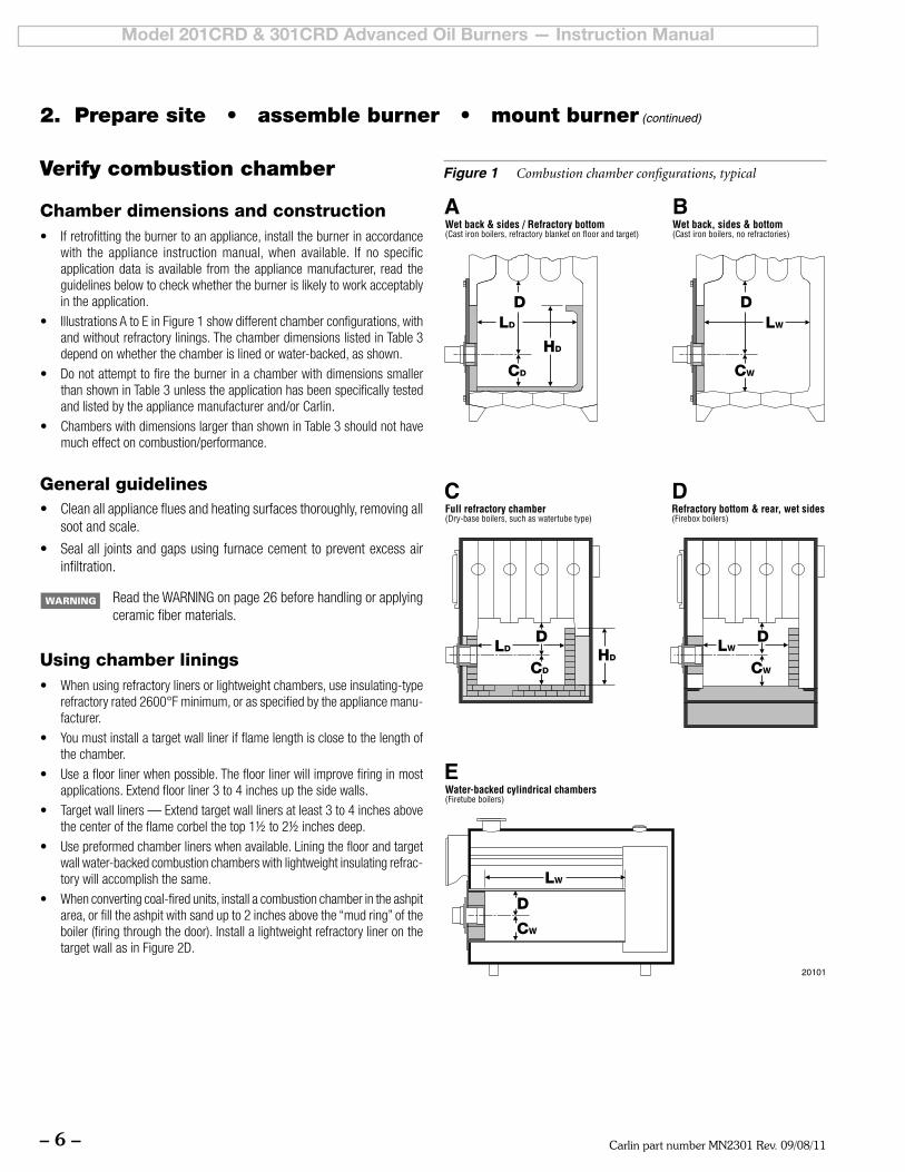
• IllustrationsAtoEinFigure1showdifferentchamberconfigurations,withandwithoutrefractorylinings.ThechamberdimensionslistedinTable3depend on whether the chamber is lined or water-backed, as shown.
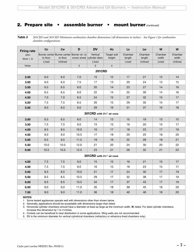
• DonotattempttofiretheburnerinachamberwithdimensionssmallerthanshowninTable3unlesstheapplicationhasbeenspecificallytestedand listed by the appliance manufacturer and/or Carlin.
• ChamberswithdimensionslargerthanshowninTable3shouldnothavemuch effect on combustion/performance.
General guidelines• Cleanallappliancefluesandheatingsurfacesthoroughly,removingall
soot and scale.
• Sealall jointsandgapsusingfurnacecementtopreventexcessairinfiltration.
ReadtheWARNINGonpage26beforehandlingorapplyingceramic fiber materials.
Using chamber linings• Whenusingrefractorylinersorlightweightchambers,useinsulating-type
refractoryrated2600°Fminimum,orasspecifiedbytheappliancemanu-facturer.
• Youmustinstallatargetwalllinerifflamelengthisclosetothelengthofthe chamber.
• Useafloorlinerwhenpossible.Thefloorlinerwillimprovefiringinmostapplications.Extendfloorliner3to4inchesupthesidewalls.
• Targetwallliners—Extendtargetwalllinersatleast3to4inchesabovethecenteroftheflamecorbelthetop1½to2½inchesdeep.
• Usepreformedchamberlinerswhenavailable.Liningthefloorandtargetwall water-backed combustion chambers with lightweight insulating refrac-tory will accomplish the same.
• Whenconvertingcoal-firedunits,installacombustionchamberintheashpitarea, or fill the ashpit with sand up to 2 inches above the “mud ring” of the boiler (firing through the door). Install a lightweight refractory liner on the targetwallasinFigure2D.
Figure 1 Combustion chamber configurations, typical
2. Prepare site • assemble burner • mount burner (continued)
Carlin part number MN2301 Rev. 09/08/11 – 7 –
Model 201CRD & 301CRD Advanced Oil Burners — Instruction Manual
Table 3 201CRD and 301CRD Minimum combustion chamber dimensions (all dimensions in inches) - See Figure 1 for combustion chamber configurations
2. Prepare site • assemble burner • mount burner (continued)
Carlin part number MN2301 Rev. 09/08/11– 8 –
Model 201CRD & 301CRD Advanced Oil Burners — Instruction Manual
Inspect burner and components
General• Checktheairtubelength.VerifytheusablelengthofthetubeUTLwillbe
long enough (see “Mount burner in appliance”).
• Visuallyinspectallburnercomponentsandwiring.
• Verifythatwiringisintactandleadsaresecurelyconnected.
• Verifythatallburnercomponentsareingoodcondition.
Do not install or operate the burner if any component isdamaged or if burner does not comply with other guidelines of this manual and the appliance manual.
Install/check burner flange
Welded-flange burners1. Verifytheboltpatternontheappliancechambermatchestheflangepat-
tern.
2. Verifytheinsertiondepth(UTL)matchesthedepthoftheapplianceopen-ing(sotheendoftheairtubeisflushwith,orslightlyshortof,theinsidesurface of the combustion chamber).
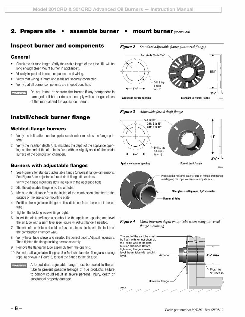
Burners with adjustable flanges1. SeeFigure2forstandardadjustableflange(universalflange)dimensions.
SeeFigure3foradjustableforceddraftflangedimensions.
Verifytheflangemountingslotslineupwiththeappliancebolts.
2. Sliptheadjustableflangeontotheairtube.
3. Measurethedistancefromtheinsideofthecombustionchambertotheoutside of the appliance mounting plate.
4. Position the adjustable flange at this distance from the end of the airtube.
5. Tightenthelockingscrewsfingertight.
6. Inserttheairtube/flangeassemblyintotheapplianceopeningandleveltheairtubewithaspiritlevel(seeFigure4).Adjustflangeifneeded.
7. Theendoftheairtubeshouldbeflush,oralmostflush,withtheinsideofthe combustion chamber wall.
8. Verifytheairtubeislevelandinsertedthecorrectdepth.Adjustifnecessary.Thentightentheflangelockingscrewssecurely.
9. Removetheflange/airtubeassemblyfromtheopening.
10.Forceddraftadjustableflanges:Use¼-inchdiameterfiberglasssealingrope,asshowninFigure3,tosealtheflangetotheairtube.
Aforceddraftadjustableflangemustbesealedto theairtube to prevent possible leakage of flue products. Failureto comply could result in severe personal injury, death or substantial property damage.
Figure 2 Standard adjustable flange (universal flange)
Figure 4 Mark insertion depth on air tube when using universal flange mounting
2. Prepare site • assemble burner • mount burner (continued)
Figure 3 Adjustable forced draft flange
Carlin part number MN2301 Rev. 09/08/11 – 9 –
Model 201CRD & 301CRD Advanced Oil Burners — Instruction Manual
Pedestal-mounted burners1. Checkthediameteroftheapplianceopening. If largerthan4½inches,
rebuildtheopeningsotheopenisreducedto4½inchesmaximum.
2. InserttheairtubeintotheapplianceopeningasinFigure4.Donotattachair tube to housing yet.
3. Slidethetubeinuntiltheendofthetubeisflushwith,orupto¼inchshortof, the inside of the combustion chamber.
4. Leveltheairtubeusingaspiritlevel.
5. Marktheairtubepositionwithapenorpencilaroundthecircumferenceof the tube.
6. Removeairtubefromtheopening
2. Prepare site • assemble burner • mount burner (continued)
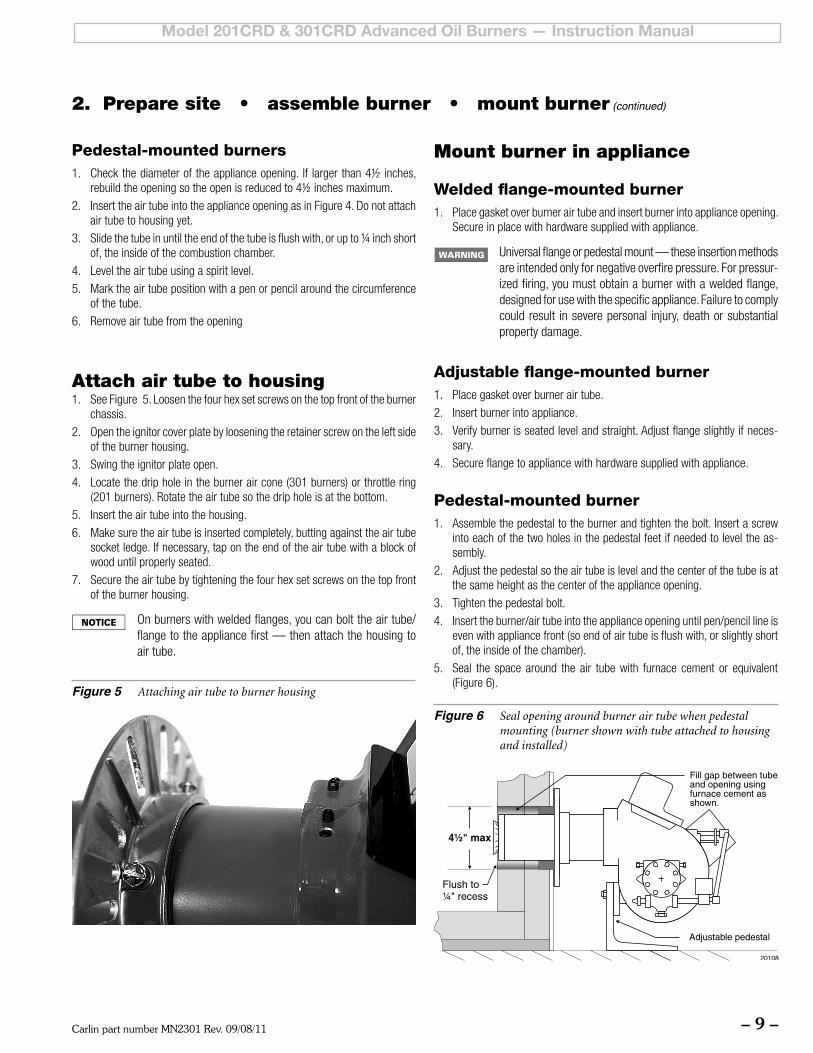
Attach air tube to housing1. SeeFigure5.Loosenthefourhexsetscrewsonthetopfrontoftheburner
chassis.
2. Opentheignitorcoverplatebylooseningtheretainerscrewontheleftsideof the burner housing.
3. Swingtheignitorplateopen.
4. Locatethedripholeintheburneraircone(301burners)orthrottlering(201 burners). Rotate the air tube so the drip hole is at the bottom.
5. Inserttheairtubeintothehousing.
6. Makesuretheairtubeisinsertedcompletely,buttingagainsttheairtubesocket ledge. If necessary, tap on the end of the air tube with a block of wood until properly seated.
7. Securetheairtubebytighteningthefourhexsetscrewsonthetopfrontof the burner housing.
Onburnerswithweldedflanges,youcanbolttheairtube/flangetotheappliancefirst—thenattachthehousingtoair tube.
Figure 5 Attaching air tube to burner housing
Mount burner in appliance
Welded flange-mounted burner1. Place gasket over burner air tube and insert burner into appliance opening.
Secure in place with hardware supplied with appliance.
Universalflangeorpedestalmount—theseinsertionmethodsare intended only for negative overfire pressure. For pressur-izedfiring,youmustobtainaburnerwithaweldedflange,designed for use with the specific appliance. Failure to comply could result in severe personal injury, death or substantial property damage.
Adjustable flange-mounted burner1. Place gasket over burner air tube.
2. Insert burner into appliance.
3. Verifyburnerisseatedlevelandstraight.Adjustflangeslightlyifneces-sary.
4. Secureflangetoappliancewithhardwaresuppliedwithappliance.
Pedestal-mounted burner1. Assemblethepedestaltotheburnerandtightenthebolt.Insertascrew
into each of the two holes in the pedestal feet if needed to level the as-sembly.
2. Adjustthepedestalsotheairtubeislevelandthecenterofthetubeisatthe same height as the center of the appliance opening.
3. Tightenthepedestalbolt.
4. Insert the burner/air tube into the appliance opening until pen/pencil line is evenwithappliancefront(soendofairtubeisflushwith,orslightlyshortof, the inside of the chamber).
5. Seal the space around the air tube with furnace cement or equivalent(Figure6).
Figure 6 Seal opening around burner air tube when pedestal mounting (burner shown with tube attached to housing and installed)
Carlin part number MN2301 Rev. 09/08/11– 10 –
Model 201CRD & 301CRD Advanced Oil Burners — Instruction Manual
Removing/installing head assembly Use care when handling burner components after the burner
has been firing. Components can be hot and could cause severe personal injury.
Removing the combustion head assemblyYouwillneedtoremovethecombustionheadassemblyforinspectionofthe assembly, replacement of the oil nozzle or adjustment of electrodes. To remove the assembly:
1. Loosenthescrewontheleftsideoftheburnerhousingthatsecurestheignitor plate in place. Swing the ignitor plate open.
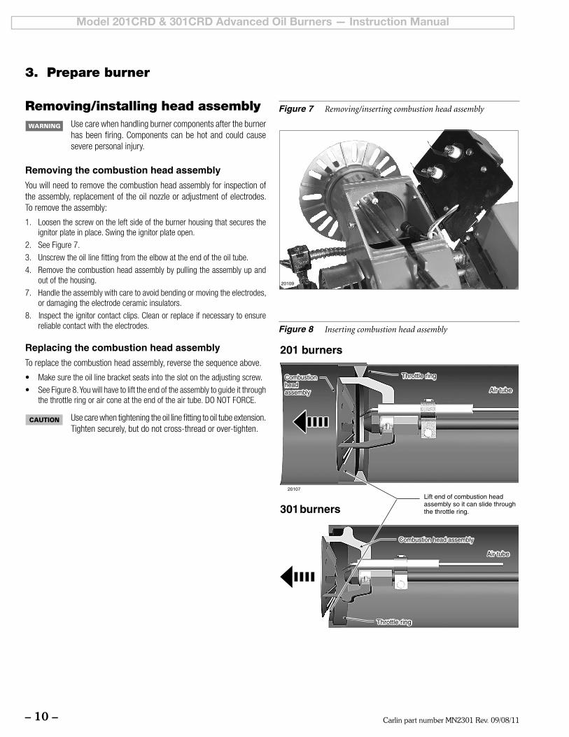
2. SeeFigure7.
3. Unscrewtheoillinefittingfromtheelbowattheendoftheoiltube.
4. Remove the combustion head assembly by pulling the assembly up and out of the housing.
7. Handletheassemblywithcaretoavoidbendingormovingtheelectrodes,or damaging the electrode ceramic insulators.
8. Inspect the ignitor contact clips. Clean or replace if necessary to ensure reliable contact with the electrodes.
Replacing the combustion head assemblyTo replace the combustion head assembly, reverse the sequence above.
• Makesuretheoillinebracketseatsintotheslotontheadjustingscrew.
• SeeFigure8.Youwillhavetolifttheendoftheassemblytoguideitthroughthethrottleringorairconeattheendoftheairtube.DONOTFORCE.
Use care when tightening the oil line fitting to oil tube extension. Tighten securely, but do not cross-thread or over-tighten.
Figure 8 Inserting combustion head assembly
Figure 7 Removing/inserting combustion head assembly
3. Prepare burner
Carlin part number MN2301 Rev. 09/08/11 – 11 –
Model 201CRD & 301CRD Advanced Oil Burners — Instruction Manual
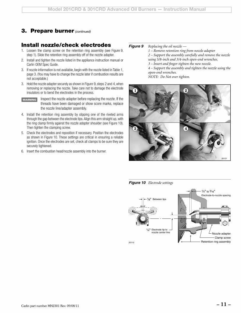
Figure 10 Electrode settings
Install nozzle/check electrodes1. Loosen the clamp screwon the retention ring assembly (see Figure9,
step 1). Slide the retention ring assembly off of the nozzle adapter.
2. Install and tighten the nozzle listed in the appliance instruction manual or CarlinOEMSpecGuide.
3. Ifnozzleinformationisnotavailable,beginwiththenozzlelistedinTable1,page3.(Youmayhavetochangethenozzlelaterifcombustionresultsarenot acceptable.)
3. HoldthenozzleadaptersecurelyasshowninFigure9,steps2and4,whenremoving or replacing the nozzle. Take care not to damage the electrode insulators or to bend the electrodes in the process.
Inspect the nozzle adapter before replacing the nozzle. If the threads have been damaged or show score marks, replace the nozzle line/adapter assembly.
4. Install the retention ring assembly by slipping one of the riveted arms throughthegapbetweentheelectrodetips.Alignthisarmstraightup,withthe ring clamp firmly against the nozzle adapter shoulder (see Figure 10). Then tighten the clamping screw.
5. Checktheelectrodesandrepositionifnecessary.Positiontheelectrodesas shown in Figure 10. These settings are critical in ensuring a reliable ignition.Oncetheelectrodesareset,checkallclampstobesuretheyaresecurely tightened.
6. Insertthecombustionhead/nozzleassemblyintotheburner.
Figure 9 Replacing the oil nozzle — 1 – Remove retention ring from nozzle adapter 2 – Support the assembly carefully and remove the nozzle using 5/8-inch and 3/4-inch open-end wrenches. 3 – Insert and finger-tighten the new nozzle. 4 – Support the assembly and tighten the nozzle using the open-end wrenches. NOTE: Do Not over tighten.
3. Prepare burner (continued)
Carlin part number MN2301 Rev. 09/08/11– 12 –
Model 201CRD & 301CRD Advanced Oil Burners — Instruction Manual
Figure 13 Combustion head/air tube combinations, typical
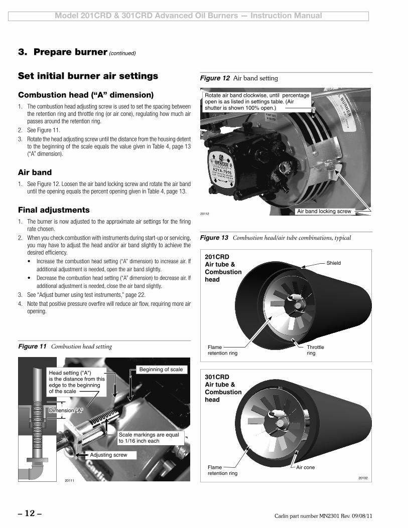
Set initial burner air settings
Combustion head (“A” dimension)1. The combustion head adjusting screw is used to set the spacing between
the retention ring and throttle ring (or air cone), regulating how much air passes around the retention ring.
2. See Figure 11.
3. RotatetheheadadjustingscrewuntilthedistancefromthehousingdetenttothebeginningofthescaleequalsthevaluegiveninTable4,page13(“A”dimension).
Air band1. SeeFigure12.Loosentheairbandlockingscrewandrotatetheairband
untiltheopeningequalsthepercentopeninggiveninTable4,page13.
Final adjustments1. The burner is now adjusted to the approximate air settings for the firing
rate chosen.
2. When you check combustion with instruments during start-up or servicing, you may have to adjust the head and/or air band slightly to achieve the desired efficiency.• Increasethecombustionheadsetting(“A”dimension)toincreaseair. If
additional adjustment is needed, open the air band slightly.
• Decreasethecombustionheadsetting(“A”dimension)todecreaseair.Ifadditional adjustment is needed, close the air band slightly.
3. See“Adjustburnerusingtestinstruments,”page22.
4. Notethatpositivepressureoverfirewillreduceairflow,requiringmoreairopening.
Figure 11 Combustion head setting
Figure 12 Air band setting
3. Prepare burner (continued)
Carlin part number MN2301 Rev. 09/08/11 – 13 –
Model 201CRD & 301CRD Advanced Oil Burners — Instruction Manual
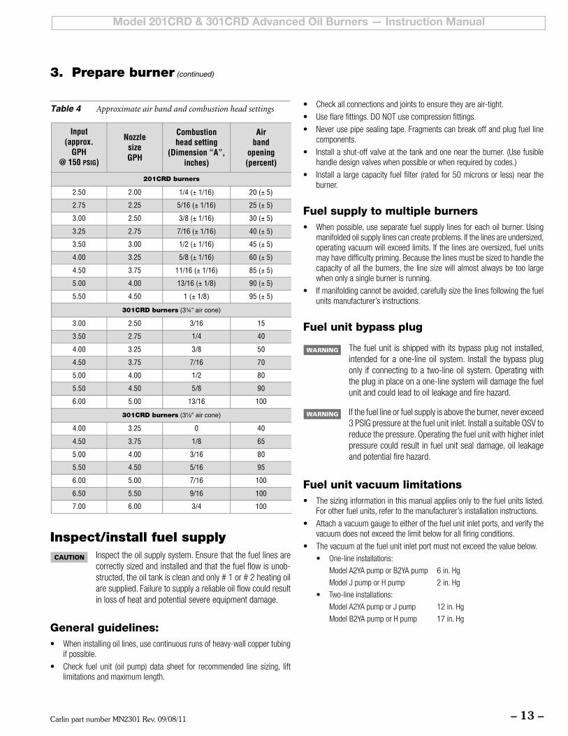
Table 4 Approximate air band and combustion head settings
3. Prepare burner (continued)
Inspect/install fuel supply Inspect the oil supply system. Ensure that the fuel lines are
correctlysizedandinstalledandthatthefuelflowisunob-structed,theoiltankiscleanandonly#1or#2heatingoilaresupplied.Failuretosupplyareliableoilflowcouldresultin loss of heat and potential severe equipment damage.
General guidelines:• Wheninstallingoillines,usecontinuousrunsofheavy-wallcoppertubing
if possible.
• Check fuel unit (oil pump) data sheet for recommended line sizing, liftlimitations and maximum length.
• Checkallconnectionsandjointstoensuretheyareair-tight.
• Useflarefittings.DONOTusecompressionfittings.
• Neverusepipesealingtape.Fragmentscanbreakoffandplugfuellinecomponents.
• Installashut-offvalveatthetankandoneneartheburner.(Usefusiblehandle design valves when possible or when required by codes.)
• Installalargecapacityfuelfilter(ratedfor50micronsorless)neartheburner.
Fuel supply to multiple burners• Whenpossible,useseparatefuelsupplylinesforeachoilburner.Using
manifolded oil supply lines can create problems. If the lines are undersized, operating vacuum will exceed limits. If the lines are oversized, fuel units mayhavedifficultypriming.Becausethelinesmustbesizedtohandlethecapacity of all the burners, the line size will almost always be too large when only a single burner is running.
• Ifmanifoldingcannotbeavoided,carefullysizethelinesfollowingthefuelunits manufacturer’s instructions.
Fuel unit bypass plug
The fuel unit is shipped with its bypass plug not installed, intended for a one-line oil system. Install the bypass plug only ifconnectingtoa two-lineoilsystem.Operatingwiththe plug in place on a one-line system will damage the fuel unit and could lead to oil leakage and fire hazard.
If the fuel line or fuel supply is above the burner, never exceed 3PSIGpressureatthefuelunitinlet.InstallasuitableOSVtoreducethepressure.Operatingthefuelunitwithhigherinletpressure could result in fuel unit seal damage, oil leakage and potential fire hazard.
Fuel unit vacuum limitations• Thesizinginformationinthismanualappliesonlytothefuelunitslisted.
For other fuel units, refer to the manufacturer’s installation instructions.
• Attachavacuumgaugetoeitherofthefuelunitinletports,andverifythevacuum does not exceed the limit below for all firing conditions.
• Thevacuumatthefuelunitinletportmustnotexceedthevaluebelow.• One-lineinstallations:
ModelA2YApumporB2YApump 6in.Hg
ModelJpumporHpump 2in.Hg
• Two-lineinstallations:
ModelA2YApumporJpump 12in.Hg
ModelB2YApumporHpump 17in.Hg
Carlin part number MN2301 Rev. 09/08/11– 14 –
Model 201CRD & 301CRD Advanced Oil Burners — Instruction Manual
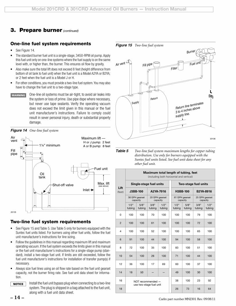
Figure 15 Two-line fuel system
Table 5 Two-line fuel system maximum lengths for copper tubing distribution. Use only for burners equipped with the Suntec fuel units listed. See fuel unit data sheet for any other fuel unit.
Two-line fuel system requirements• SeeFigure15andTable5.UseTable5onlyforburnersequippedwiththe
Suntec fuel units listed. For burners using other fuel units, follow the fuel unit manufacturer’s instructions for line sizing.
• Followtheguidelinesinthismanualregardingmaximumliftandmaximumoperating vacuum. If the fuel system exceeds the limits given in this manual or the fuel unit manufacturer’s instructions for a single-stage pump (stan-dard), install a two-stage fuel unit. If limits are still exceeded, follow the fuel unit manufacturer’s instructions for installation of transfer pump(s) if necessary.
• Alwayssizefuellinesusinganoilflowratebasedonthefuelunitgearsetcapacity, not the burner firing rate. See fuel unit data sheet for informa-tion.
Install the fuel unit bypass plug when connecting to a two-line system. The plug is shipped in a bag attached to the fuel unit, along with a fuel unit data sheet.
Figure 14 One-line fuel system
One-line fuel system requirements• SeeFigure14.
• Thestandardburnerfuelunitisasingle-stage,3450-RPMoilpump.Applythis fuel unit only on one-line systems where the fuel supply is on the same levelwith,orhigherthan,theburner.Thisensuresoilflowbygravity.
• Alsomakesurethetotalliftdoesnotexceed8feet(heightdifferencefrombottomofoiltanktofuelunit)whenthefuelunitisaModelA2YAorB2YA;or2feetwhenthefuelunitisaModelJorH.
• Forotherconditions,youmustprovideatwo-linefuelsystem.Youmayalsohave to change the fuel unit to a two-stage type.
One-lineoilsystemsmustbeair-tight,toavoidairleaksintothe system or loss of prime. Use pipe dope where necessary, but never use tape sealants. Verify the operating vacuum does not exceed the limit given in this manual or the fuel unit manufacturer’s instructions. Failure to comply could result in sever personal injury, death or substantial property damage.
3. Prepare burner (continued)
Carlin part number MN2301 Rev. 09/08/11 – 15 –
Model 201CRD & 301CRD Advanced Oil Burners — Instruction Manual
3. Prepare burner (continued)
Perform checkout procedures
Verify before starting burner:
Should overheating or an emergency occur, immediately:
•Shutoffoilsupplylinevalve.
•Undersomecircumstancespowershouldremainonforwaterpumpsorblowers.Determineproperresponsebeforeattempting start-up.
• If burner fails ignitionon several attempts, useburnerblower to purge appliance chamber before restart.
Checklist❏ Burner/applianceinstalledperapplianceinstructionmanual?
❏ Burnernozzleverifiedperappliancemanufacturer’sinstructions,CarlinOEMSpecGuideorTable1,page3?
❏ Burner/applianceinstalledperallapplicablecodes?
❏ Installation site has adequate combustion/ventilation air openings andventsystem?
❏ Fuel supply line in good condition and sized/designed cor-rectly?
❏ Oiltankhasoilandoillinevalvesareopen.
❏ Wiringinstalledperburnermanualandapplianceinstructions?
❏ Burner, appliance and all components inspected and in goodcondition?
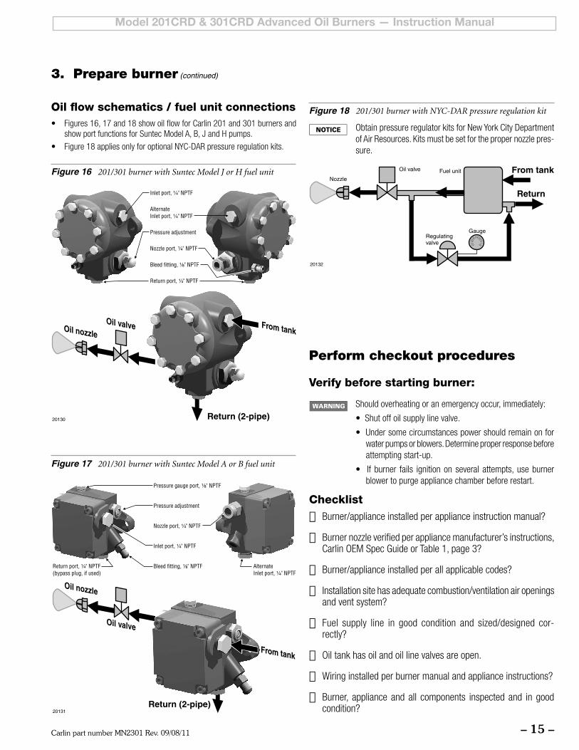
Oil flow schematics / fuel unit connections• Figures16,17and18showoilflowforCarlin201and301burnersand
showportfunctionsforSuntecModelA,B,JandHpumps.
• Figure18appliesonlyforoptionalNYC-DARpressureregulationkits.
Figure 16 201/301 burner with Suntec Model J or H fuel unit
Figure 17 201/301 burner with Suntec Model A or B fuel unit
Figure 18 201/301 burner with NYC-DAR pressure regulation kit
ObtainpressureregulatorkitsforNewYorkCityDepartmentofAirResources.Kitsmustbesetforthepropernozzlepres-sure.
Carlin part number MN2301 Rev. 09/08/11– 16 –
Model 201CRD & 301CRD Advanced Oil Burners — Instruction Manual
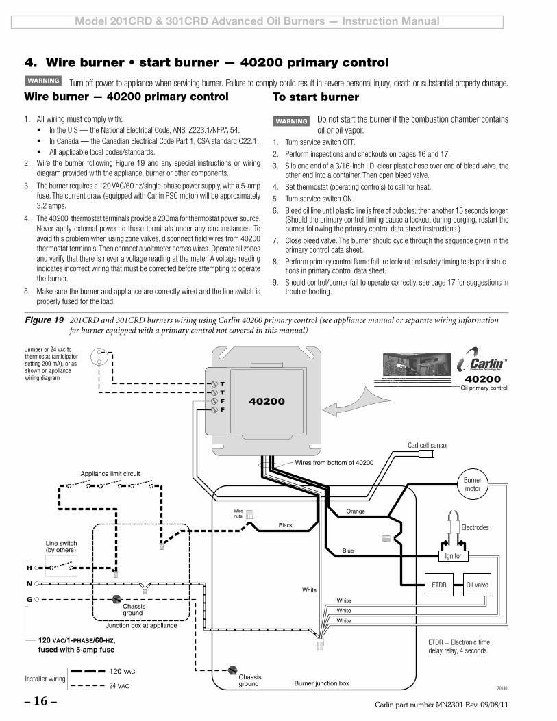
Wire burner — 40200 primary control
1. Allwiringmustcomplywith:• IntheU.S—theNationalElectricalCode,ANSIZ223.1/NFPA54.• InCanada—theCanadianElectricalCodePart1,CSAstandardC22.1.• Allapplicablelocalcodes/standards.
2. Wire the burner following Figure 19 and any special instructions orwiringdiagram provided with the appliance, burner or other components.
3. Theburnerrequiresa120VAC/60hz/single-phasepowersupply,witha5-ampfuse. The current draw (equipped with Carlin PSC motor) will be approximately 3.2amps.
4. The 40200 thermostat terminals provide a 200ma for thermostat power source. Never apply external power to these terminals under any circumstances. To avoid this problem when using zone valves, disconnect field wires from 40200 thermostatterminals.Thenconnectavoltmeteracrosswires.Operateallzonesandverifythatthereisneveravoltagereadingatthemeter.Avoltagereadingindicates incorrect wiring that must be corrected before attempting to operate the burner.
5. Makesuretheburnerandappliancearecorrectlywiredandthelineswitchisproperly fused for the load.
To start burner
Donotstarttheburnerifthecombustionchambercontainsoil or oil vapor.
1. TurnserviceswitchOFF.
2. Performinspectionsandcheckoutsonpages16and17.
3. Sliponeendofa3/16-inchI.D.clearplastichoseoverendofbleedvalve,theother end into a container. Then open bleed valve.
4. Set thermostat (operating controls) to call for heat.
5. TurnserviceswitchON.
6. Bleedoillineuntilplasticlineisfreeofbubbles;thenanother15secondslonger.(Should the primary control timing cause a lockout during purging, restart the burner following the primary control data sheet instructions.)
7. Closebleedvalve.Theburnershouldcyclethroughthesequencegivenintheprimary control data sheet.
8. Performprimarycontrolflamefailurelockoutandsafetytimingtestsperinstruc-tions in primary control data sheet.
9. Shouldcontrol/burnerfailtooperatecorrectly,seepage17forsuggestionsintroubleshooting.
4. Wire burner • start burner — 40200 primary control
Figure 19 201CRD and 301CRD burners wiring using Carlin 40200 primary control (see appliance manual or separate wiring information for burner equipped with a primary control not covered in this manual)
Turn off power to appliance when servicing burner. Failure to comply could result in severe personal injury, death or substantial property damage.
Carlin part number MN2301 Rev. 09/08/11 – 17 –
Model 201CRD & 301CRD Advanced Oil Burners — Instruction Manual
Start-up & operation
Do not start the burner if the combustion chamber contains oil or oil vapor.
Per UL requirements, the control will not turn on if the cad cell senses flame dur-ing the self-test. If the cad cell sees light (flame) at the beginning of a cycle, the control will wait until it no longer senses the problem.
Service & Troubleshooting
Burner (control) will not come onNo power to control
• Check line voltage to the control (at least 102 vac).• Check all electrical connections.
Control is in lockout• Press the reset button for 3 seconds.
CAD cell seeing light• Remove one lead from FF terminal on the control. Press
and hold the reset button for 3 seconds. If voltmeter shows power between control white and black wires, and T-T circuit is closed, but control does not start, replace the control.
If control starts when receiving power on the black wire and T-T circuit is closed, check for:• light is leaking into the burner housing, or
• CAD cell is defective, or
• there is a problem with the CAD cell wiring or holder.• If appliance was recently shut down, CAD cell may see
residual hot spots in chamber. To troubleshoot:
• Check CAD cell by unplugging it and measuring the resistance across its pins: dark resistance at least 50 kohms; room light resistance less than 10 kohms. Re-place if necessary. If the CAD cell functions properly, reinstall the cell and close the burner housing.
• Check for stray light by measuring the CAD cell re-sistance looking into the inactive combustion chamber. It should read at least 50 kohms.
Control will not reset• If the control will not reset, the Safety Monitoring Circuit may
be detecting an internal control problem. Replace the control.
Repeated flame failures (burner lights, but shuts down)
Check for: • CAD cell is defective.• Air leaking into oil line causing flame out — Check oil line
connections and filter gasket.• Defective nozzle causing flame to be erratic — Change
nozzle.• Excessive airflow or draft causing flame to leave burner
head Check for proper air shutter setting and draft.
• Excessive back pressure causing flame to be erratic — Check appliance and flue for sooting/plugging.
Control locks out after TFICheck for:
• No oil to burner — Check oil supply, filter, lines.• Shorted electrodes — Inspect for cracked porcelain and
replace as needed.• Poor spark — Check electrode spacing and condition
per burner manual. Replace or realign if necessary.• Nozzle clogged — Replace nozzle.• Airflow too high — Check air shutter setting.• Ignitor module defective — Replace if no spark.• CAD cell defective.• Oil valve stuck in closed position. • Check wiring connections.
Power ON Open all manual oil line valves. Close the line switch.
Reset Press and hold the reset button for 3 seconds, then release. This will reset the control at any time during its operation.
Stand-by (No call for heat) Control waits for power to be applied to the black wire (from appliance limit circuit).
Call for heat Set thermostat (or limit) to call for heat. Ther-mostat circuit must be closed and power coming to black wire from limit circuit.
Burner on The ignitor and motor start. Four seconds later, the electronic time delay relay allows the oil valve to open.
TFI The cad cell must sense flame within the control’s trial for ignition (TFI) timing — 15 seconds for 40200 control. After cad cell senses flame, the ignitor stays on another 10 seconds (flame stabilization period).
Run The burner continues firing during call for heat if the cad cell is sensing flame.
Lockout If cad cell does not sense flame within the TFI timing (15 seconds), lockout occurs.
To Reset Push in and hold reset button for 3 seconds, then release. This will reset control at any time during operation.
Flame failure If the cad cell loses flame signal during operation (after the TFI), the burner shuts off within 1.3 seconds. Recycle: After 60 to 90 seconds the control will restart (Burner on mode).
Burner off Set thermostat (or aquastat) to stop call for heat. The burner shuts off within 2 seconds after end of call for heat.
Stand-by Control remains in stand-by mode until limit circuit sends power to the black wire and T-T circuit closes (call for heat).
Power loss If power to control/burner is interrupted during a normal run cycle, the control will begin a normal cycle again after power is restored.
Carlin part number MN2301 Rev. 09/08/11– 18 –
Model 201CRD & 301CRD Advanced Oil Burners — Instruction Manual
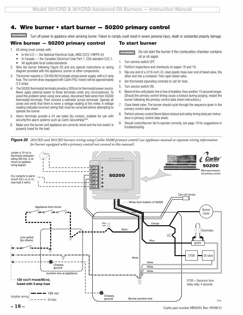
Wire burner — 50200 primary control1. Allwiringmustcomplywith:
• IntheU.S—theNationalElectricalCode,ANSIZ223.1/NFPA54.• InCanada—theCanadianElectricalCodePart1,CSAstandardC22.1.• Allapplicablelocalcodes/standards.
2. Wire the burner following Figure 20 and any special instructions or wiring diagram provided with the appliance, burner or other components.
3. Theburnerrequiresa120VAC/60hz/single-phasepowersupply,witha5-ampfuse. The current draw (equipped with Carlin PSC motor) will be approximately 3.2amps.
4. The50200thermostatterminalsprovidea200maforthermostatpowersource.Never apply external power to these terminals under any circumstances. To avoidthisproblemwhenusingzonevalves,disconnectfieldwiresfrom50200thermostatterminals.Thenconnectavoltmeteracrossterminals.Operateallzonesandverifythatthereisneveravoltagereadingatthemeter.Avoltagereading indicates incorrect wiring that must be corrected before attempting to operate the burner.
5. Alarm terminals provide a 24 vac-rated dry contact, suitable for use withsecurity/firealarmsystemssuchasCarlinSecureHeat™.
6. Makesuretheburnerandappliancearecorrectlywiredandthelineswitchisproperly fused for the load.
To start burner
Donotstarttheburnerifthecombustionchambercontainsoil or oil vapor.
1. TurnserviceswitchOFF.
2. Performinspectionsandcheckoutsonpages18and19.
3. Sliponeendofa3/16-inchI.D.clearplastichoseoverendofbleedvalve,theother end into a container. Then open bleed valve.
4. Set thermostat (operating controls) to call for heat.
5. TurnserviceswitchON.
6. Bleedoillineuntilplasticlineisfreeofbubbles;thenanother15secondslonger.(Should the primary control timing cause a lockout during purging, restart the burner following the primary control data sheet instructions.)
7. Closebleedvalve.Theburnershouldcyclethroughthesequencegivenintheprimary control data sheet.
8. Performprimarycontrolflamefailurelockoutandsafetytimingtestsperinstruc-tions in primary control data sheet.
9. Shouldcontrol/burnerfailtooperatecorrectly,seepage19forsuggestionsintroubleshooting.
4. Wire burner • start burner — 50200 primary control
Figure 20 201CRD and 301CRD burners wiring using Carlin 50200 primary control (see appliance manual or separate wiring information for burner equipped with a primary control not covered in this manual)
Turn off power to appliance when servicing burner. Failure to comply could result in severe personal injury, death or substantial property damage.
Carlin part number MN2301 Rev. 09/08/11 – 19 –
Model 201CRD & 301CRD Advanced Oil Burners — Instruction Manual
Start-up & operation
Do not start the burner if the combustion chamber contains oil or oil vapor.
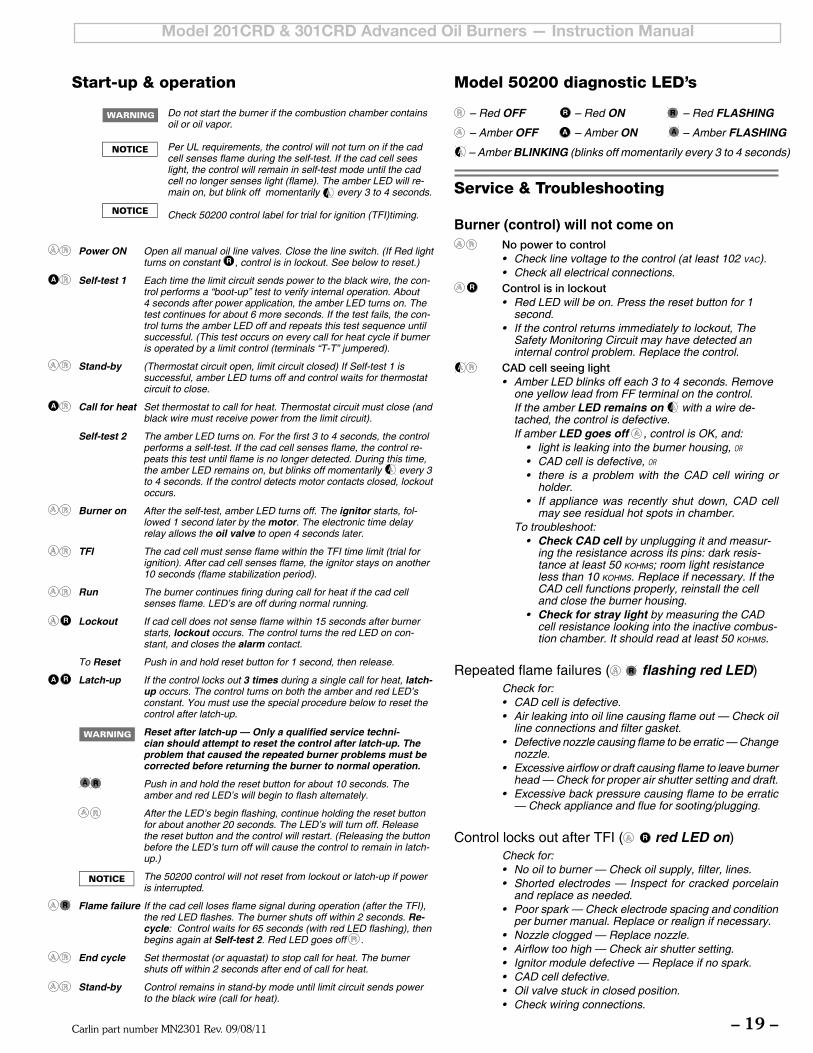
Per UL requirements, the control will not turn on if the cad cell senses flame during the self-test. If the cad cell sees light, the control will remain in self-test mode until the cad cell no longer senses light (flame). The amber LED will re-main on, but blink off momentarily every 3 to 4 seconds.
Check 50200 control label for trial for ignition (TFI)timing.
Model 50200 diagnostic LED’s
– Red OFF – Red ON – Red FLASHING
– Amber OFF – Amber ON – Amber FLASHING
– Amber BLINKING (blinks off momentarily every 3 to 4 seconds)
Service & Troubleshooting
Burner (control) will not come on No power to control
• Check line voltage to the control (at least 102 vac). • Check all electrical connections.
Control is in lockout • Red LED will be on. Press the reset button for 1
second. • If the control returns immediately to lockout, The
Safety Monitoring Circuit may have detected an internal control problem. Replace the control.
CAD cell seeing light • Amber LED blinks off each 3 to 4 seconds. Remove
one yellow lead from FF terminal on the control. If the amber LED remains on with a wire de-
tached, the control is defective. If amber LED goes off , control is OK, and:
• light is leaking into the burner housing, or
• CAD cell is defective, or
• there is a problem with the CAD cell wiring or holder.
• If appliance was recently shut down, CAD cell may see residual hot spots in chamber.
To troubleshoot:• Check CAD cell by unplugging it and measur-
ing the resistance across its pins: dark resis-tance at least 50 kohms; room light resistance less than 10 kohms. Replace if necessary. If the CAD cell functions properly, reinstall the cell and close the burner housing.
• Check for stray light by measuring the CAD cell resistance looking into the inactive combus-tion chamber. It should read at least 50 kohms.
Repeated flame failures ( flashing red LED) Check for: • CAD cell is defective. • Air leaking into oil line causing flame out — Check oil
line connections and filter gasket. • Defective nozzle causing flame to be erratic — Change
nozzle. • Excessive airflow or draft causing flame to leave burner
head — Check for proper air shutter setting and draft. • Excessive back pressure causing flame to be erratic
— Check appliance and flue for sooting/plugging.
Control locks out after TFI ( red LED on) Check for: • No oil to burner — Check oil supply, filter, lines. • Shorted electrodes — Inspect for cracked porcelain
and replace as needed. • Poor spark — Check electrode spacing and condition
per burner manual. Replace or realign if necessary. • Nozzle clogged — Replace nozzle. • Airflow too high — Check air shutter setting. • Ignitor module defective — Replace if no spark. • CAD cell defective. • Oil valve stuck in closed position. • Check wiring connections.
Power ON Open all manual oil line valves. Close the line switch. (If Red light turns on constant , control is in lockout. See below to reset.)
Self-test 1 Each time the limit circuit sends power to the black wire, the con-trol performs a “boot-up” test to verify internal operation. About 4 seconds after power application, the amber LED turns on. The test continues for about 6 more seconds. If the test fails, the con-trol turns the amber LED off and repeats this test sequence until successful. (This test occurs on every call for heat cycle if burner is operated by a limit control (terminals “T-T” jumpered).
Stand-by (Thermostat circuit open, limit circuit closed) If Self-test 1 is successful, amber LED turns off and control waits for thermostat circuit to close.
Call for heat Set thermostat to call for heat. Thermostat circuit must close (and black wire must receive power from the limit circuit).
Self-test 2 The amber LED turns on. For the first 3 to 4 seconds, the control performs a self-test. If the cad cell senses flame, the control re-peats this test until flame is no longer detected. During this time, the amber LED remains on, but blinks off momentarily every 3 to 4 seconds. If the control detects motor contacts closed, lockout occurs.
Burner on After the self-test, amber LED turns off. The ignitor starts, fol-lowed 1 second later by the motor. The electronic time delay relay allows the oil valve to open 4 seconds later.
TFI The cad cell must sense flame within the TFI time limit (trial for ignition). After cad cell senses flame, the ignitor stays on another 10 seconds (flame stabilization period).
Run The burner continues firing during call for heat if the cad cell senses flame. LED’s are off during normal running.
Lockout If cad cell does not sense flame within 15 seconds after burner starts, lockout occurs. The control turns the red LED on con-stant, and closes the alarm contact.
To Reset Push in and hold reset button for 1 second, then release.
Latch-up If the control locks out 3 times during a single call for heat, latch-up occurs. The control turns on both the amber and red LED’s constant. You must use the special procedure below to reset the control after latch-up.
Reset after latch-up — Only a qualified service techni-cian should attempt to reset the control after latch-up. The problem that caused the repeated burner problems must be corrected before returning the burner to normal operation.
Push in and hold the reset button for about 10 seconds. The amber and red LED’s will begin to flash alternately.
After the LED’s begin flashing, continue holding the reset button for about another 20 seconds. The LED’s will turn off. Release the reset button and the control will restart. (Releasing the button before the LED’s turn off will cause the control to remain in latch-up.)
The 50200 control will not reset from lockout or latch-up if power is interrupted.
Flame failure If the cad cell loses flame signal during operation (after the TFI), the red LED flashes. The burner shuts off within 2 seconds. Re-cycle: Control waits for 65 seconds (with red LED flashing), then begins again at Self-test 2. Red LED goes off .
End cycle Set thermostat (or aquastat) to stop call for heat. The burner shuts off within 2 seconds after end of call for heat.
Stand-by Control remains in stand-by mode until limit circuit sends power to the black wire (call for heat).
Carlin part number MN2301 Rev. 09/08/11– 20 –
Model 201CRD & 301CRD Advanced Oil Burners — Instruction Manual
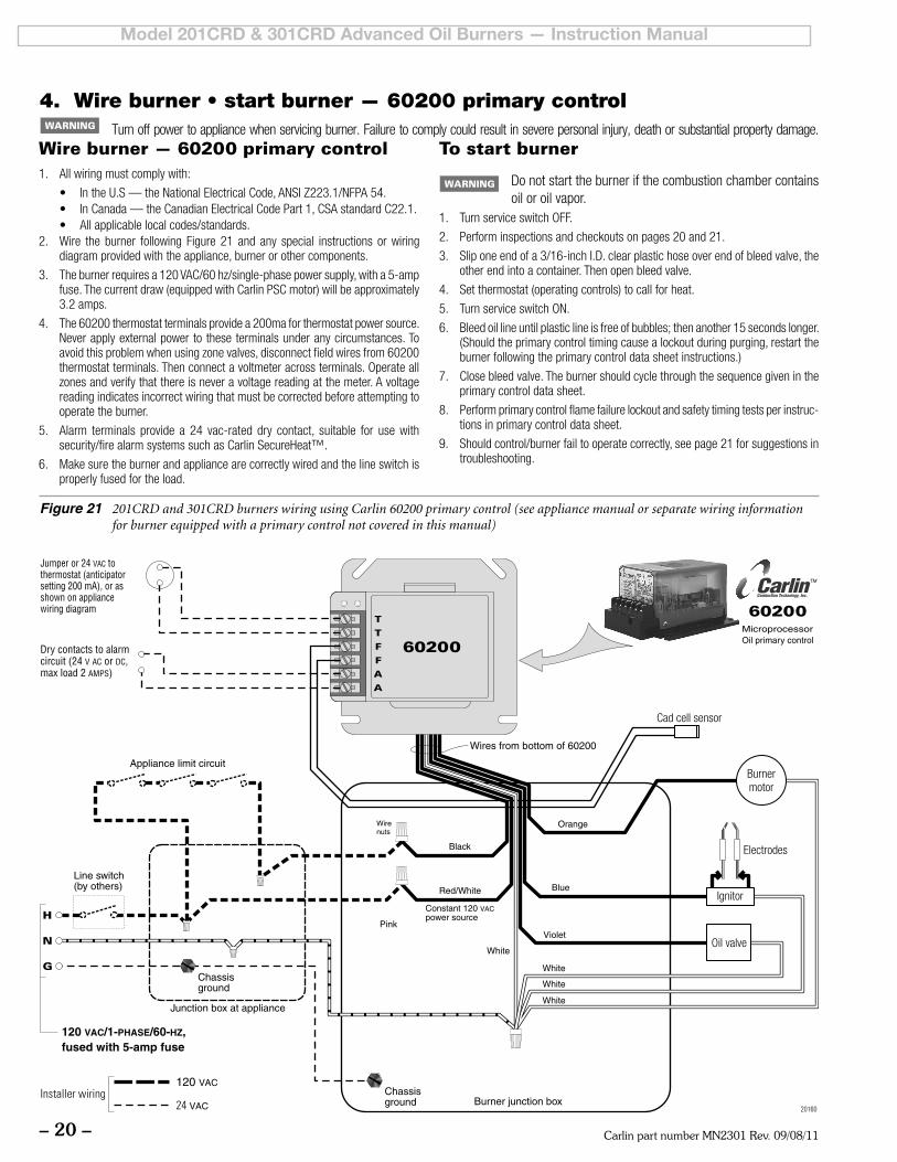
Figure 21 201CRD and 301CRD burners wiring using Carlin 60200 primary control (see appliance manual or separate wiring information for burner equipped with a primary control not covered in this manual)
4. Wire burner • start burner — 60200 primary control
Wire burner — 60200 primary control1. Allwiringmustcomplywith:
• IntheU.S—theNationalElectricalCode,ANSIZ223.1/NFPA54.• InCanada—theCanadianElectricalCodePart1,CSAstandardC22.1.• Allapplicablelocalcodes/standards.
2. Wire the burner following Figure 21 and any special instructions or wiring diagram provided with the appliance, burner or other components.
3. Theburnerrequiresa120VAC/60hz/single-phasepowersupply,witha5-ampfuse. The current draw (equipped with Carlin PSC motor) will be approximately 3.2amps.
4. The60200thermostatterminalsprovidea200maforthermostatpowersource.Never apply external power to these terminals under any circumstances. To avoidthisproblemwhenusingzonevalves,disconnectfieldwiresfrom60200thermostatterminals.Thenconnectavoltmeteracrossterminals.Operateallzonesandverifythatthereisneveravoltagereadingatthemeter.Avoltagereading indicates incorrect wiring that must be corrected before attempting to operate the burner.
5. Alarm terminals provide a 24 vac-rated dry contact, suitable for use withsecurity/firealarmsystemssuchasCarlinSecureHeat™.
6. Makesuretheburnerandappliancearecorrectlywiredandthelineswitchisproperly fused for the load.
To start burner
Donotstarttheburnerifthecombustionchambercontainsoil or oil vapor.
1. TurnserviceswitchOFF.
2. Perform inspections and checkouts on pages 20 and 21.
3. Sliponeendofa3/16-inchI.D.clearplastichoseoverendofbleedvalve,theother end into a container. Then open bleed valve.
4. Set thermostat (operating controls) to call for heat.
5. TurnserviceswitchON.
6. Bleedoillineuntilplasticlineisfreeofbubbles;thenanother15secondslonger.(Should the primary control timing cause a lockout during purging, restart the burner following the primary control data sheet instructions.)
7. Closebleedvalve.Theburnershouldcyclethroughthesequencegivenintheprimary control data sheet.
8. Performprimarycontrolflamefailurelockoutandsafetytimingtestsperinstruc-tions in primary control data sheet.
9. Shouldcontrol/burnerfailtooperatecorrectly,seepage21forsuggestionsintroubleshooting.
Turn off power to appliance when servicing burner. Failure to comply could result in severe personal injury, death or substantial property damage.
Carlin part number MN2301 Rev. 09/08/11 – 21 –
Model 201CRD & 301CRD Advanced Oil Burners — Instruction Manual
Start-up & operation
Do not start the burner if the combustion chamber contains oil or oil vapor.
Per UL requirements, the control will not turn on if the cad cell senses flame during the self-test. If the cad cell sees light, the control will remain in self-test mode until the cad cell no longer senses light (flame). The amber LED will remain on, but blink off momentarily every 3 to 4 seconds.
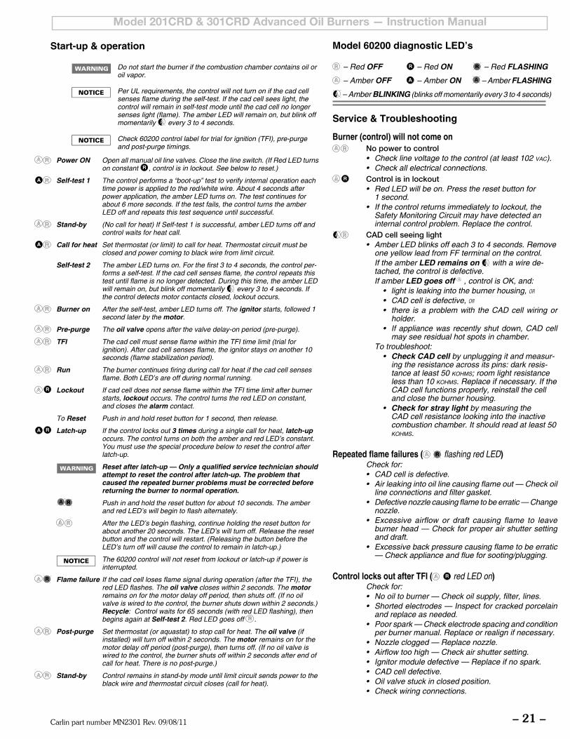
Check 60200 control label for trial for ignition (TFI), pre-purge and post-purge timings.
Model 60200 diagnostic LED’s
– Red OFF – Red ON – Red FLASHING
– Amber OFF – Amber ON – Amber FLASHING
– Amber BLINKING (blinks off momentarily every 3 to 4 seconds)
Service & Troubleshooting
Burner (control) will not come on No power to control
• Check line voltage to the control (at least 102 vac). • Check all electrical connections.
Control is in lockout • Red LED will be on. Press the reset button for
1 second. • If the control returns immediately to lockout, the
Safety Monitoring Circuit may have detected an internal control problem. Replace the control.
CAD cell seeing light • Amber LED blinks off each 3 to 4 seconds. Remove
one yellow lead from FF terminal on the control. If the amber LED remains on with a wire de-
tached, the control is defective. If amber LED goes off , control is OK, and:
• light is leaking into the burner housing, or
• CAD cell is defective, or
• there is a problem with the CAD cell wiring or holder.
• If appliance was recently shut down, CAD cell may see residual hot spots in chamber.
To troubleshoot:• Check CAD cell by unplugging it and measur-
ing the resistance across its pins: dark resis-tance at least 50 kohms; room light resistance less than 10 kohms. Replace if necessary. If the CAD cell functions properly, reinstall the cell and close the burner housing.
• Check for stray light by measuring the CAD cell resistance looking into the inactive combustion chamber. It should read at least 50 kohms.
Repeated flame failures ( flashing red LED) Check for: • CAD cell is defective. • Air leaking into oil line causing flame out — Check oil
line connections and filter gasket. • Defective nozzle causing flame to be erratic — Change
nozzle. • Excessive airflow or draft causing flame to leave
burner head — Check for proper air shutter setting and draft.
• Excessive back pressure causing flame to be erratic — Check appliance and flue for sooting/plugging.
Control locks out after TFI ( red LED on) Check for: • No oil to burner — Check oil supply, filter, lines. • Shorted electrodes — Inspect for cracked porcelain
and replace as needed. • Poor spark — Check electrode spacing and condition
per burner manual. Replace or realign if necessary. • Nozzle clogged — Replace nozzle. • Airflow too high — Check air shutter setting. • Ignitor module defective — Replace if no spark. • CAD cell defective. • Oil valve stuck in closed position. • Check wiring connections.
Power ON Open all manual oil line valves. Close the line switch. (If Red LED turns on constant , control is in lockout. See below to reset.)
Self-test 1 The control performs a “boot-up” test to verify internal operation each time power is applied to the red/white wire. About 4 seconds after power application, the amber LED turns on. The test continues for about 6 more seconds. If the test fails, the control turns the amber LED off and repeats this test sequence until successful.
Stand-by (No call for heat) If Self-test 1 is successful, amber LED turns off and control waits for heat call.
Call for heat Set thermostat (or limit) to call for heat. Thermostat circuit must be closed and power coming to black wire from limit circuit.
Self-test 2 The amber LED turns on. For the first 3 to 4 seconds, the control per-forms a self-test. If the cad cell senses flame, the control repeats this test until flame is no longer detected. During this time, the amber LED will remain on, but blink off momentarily every 3 to 4 seconds. If the control detects motor contacts closed, lockout occurs.
Burner on After the self-test, amber LED turns off. The ignitor starts, followed 1 second later by the motor.
Pre-purge The oil valve opens after the valve delay-on period (pre-purge).
TFI The cad cell must sense flame within the TFI time limit (trial for ignition). After cad cell senses flame, the ignitor stays on another 10 seconds (flame stabilization period).
Run The burner continues firing during call for heat if the cad cell senses flame. Both LED’s are off during normal running.
Lockout If cad cell does not sense flame within the TFI time limit after burner starts, lockout occurs. The control turns the red LED on constant, and closes the alarm contact.
To Reset Push in and hold reset button for 1 second, then release.
Latch-up If the control locks out 3 times during a single call for heat, latch-up occurs. The control turns on both the amber and red LED’s constant. You must use the special procedure below to reset the control after latch-up.
Reset after latch-up — Only a qualified service technician should attempt to reset the control after latch-up. The problem that caused the repeated burner problems must be corrected before returning the burner to normal operation.
Push in and hold the reset button for about 10 seconds. The amber and red LED’s will begin to flash alternately.
After the LED’s begin flashing, continue holding the reset button for about another 20 seconds. The LED’s will turn off. Release the reset button and the control will restart. (Releasing the button before the LED’s turn off will cause the control to remain in latch-up.)
The 60200 control will not reset from lockout or latch-up if power is interrupted.
Flame failure If the cad cell loses flame signal during operation (after the TFI), the red LED flashes. The oil valve closes within 2 seconds. The motor remains on for the motor delay off period, then shuts off. (If no oil valve is wired to the control, the burner shuts down within 2 seconds.) Recycle: Control waits for 65 seconds (with red LED flashing), then begins again at Self-test 2. Red LED goes off .
Post-purge Set thermostat (or aquastat) to stop call for heat. The oil valve (if installed) will turn off within 2 seconds. The motor remains on for the motor delay off period (post-purge), then turns off. (If no oil valve is wired to the control, the burner shuts off within 2 seconds after end of call for heat. There is no post-purge.)
Stand-by Control remains in stand-by mode until limit circuit sends power to the black wire and thermostat circuit closes (call for heat).
Carlin part number MN2301 Rev. 09/08/11– 22 –
Model 201CRD & 301CRD Advanced Oil Burners — Instruction Manual
5. Adjustment and verification
Adjust burner using test instruments
1. Operateburnerfor15minutesbeforemakingfinaladjustmentsusingtestequipment.
2. Check for leaks in fuel piping.
Inspect fuel piping system for leaks. Repair any leaks to avoid fire hazard from oil leakage or combustion problems due to air infiltration into oil.
3. Inspectflame• Lookatflamethroughappliancecombustionchamberobservationport.
Theflameshouldbewell-definedandshouldnotimpingeonanyappliancesurface.(Ifyoumakeairchangeslater,inspecttheflameagain.)
Donotattempttoconfirmcombustionsimplybyinspectingtheflamevisually.Youmustusecombustiontestinstruments.Failure to properly verify/adjust combustion could allow unsafe operation of the burner, resulting in severe personal injury, death or substantial property damage.
4. Inserttestprobeintoventsampleopeningtosampleflueproducts.
5. With theburnerequippedwith thecorrectoil nozzle, combustionheadsettingandairbandsetting,theflueproductswillusuallycontainbetween11%and12%CO
2(5.9%and3.8%O
2)andzero(Bacharach)smoke.
6. Usecombustiontestequipmenttoverifythatburnerisproperlysetupforyourinstallation,withintherangelistedinTable3.Applianceswithpositivepressure in the chamber may require a wider air opening. See appliance instructions for details. Verify/adjust settings by testing with instruments.a. Checksmoke.ItshouldbezeroontheBacharachscale.
b. Settheappliancefluedamperorbarometricdraftregulatorsothedraftorpressure in the vent complies with the appliance manufacturer’s instruc-tions.
c. If no draft setting information is available, set the draft to –0.01 to –0.02 inchesw.c.attheapplianceflueoutlet.
Heatingunitsdesignedfornaturaldraftoperationarenormallyset for a slightly negative pressure, usually –0.01 to –0.02 inchesw.c.draftatthecombustionchambertestport.Ap-pliances designed for forced draft (positive pressure in the chamber) must be air-tight to prevent exfiltration of harmful combustion products. Failure to properly set draft for the appliance could result in severe personal injury or death.
d. CheckpercentofCO2(orO
2). Fine tune the burner, if necessary, by slightly
adjusting the head position for more or less air.
e. Each time you change the burner air band or combustion head setting, you will have to check and possibly adjust the draft.
f. Rechecksmoke(shouldbezero)andflueorchamberpressure/draft(adjustif necessary and retest).
Allinstallationsshouldbecheckedafteronetotwoweeksofoperation to ensure the appliance/burner units are operating correctly.
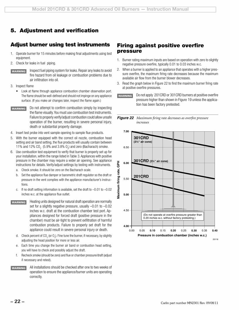
Figure 22 Maximum firing rate decreases as overfire pressure increases
Firing against positive overfire pressure
1. Burnerratingmaximuminputsarebasedonoperationwithzerotoslightlynegativepressureoverfire,typically0.01to0.03inchesw.c.
2. When a burner is applied to an appliance that operates with a higher pres-sure overfire, the maximum firing rate decreases because the maximum availableairflowfromtheburnerblowerdecreases.
3. ReadthegraphbelowinFigure22tofindthemaximumburnerfiringrateat positive overfire pressures.
Donotapply201CRDor301CRDburnersatpositiveoverfirepressurehigherthanshowninFigure19unlesstheapplica-tion has been factory pretested.
Carlin part number MN2301 Rev. 09/08/11 – 23 –
Model 201CRD & 301CRD Advanced Oil Burners — Instruction Manual
Verify burner/appliance operation
Check burner / appliance / controls operation❏ Test operating and limit controls on appliance as specified in appliance
instructions.
❏ Check operation of the primary control by forcing lockout to occur. For primary controls that enter latch-up after multiple lockouts, force latch-up to occur as well. Reset primary control per control data sheet instructions after each test.
❏ Start and stop the burner several times, allowing the primary control to sequence through normal operation. Verify correct operation of burner and primary control throughout.
Verify vent system operation❏ Verifyventisoperatingcorrectlyandflueproductsareproperlyexhausted
from building. If the building contains any exhaust fans or conditions that could affect vent performance, check burner/appliance/vent operation with exhaust fans (or other conditions) operating.
Combustion/ventilation air❏ Verify combustion/ventilation air openings are not/will not be obstructed.
❏ Verify air opening louvers are fully open.
❏ If louvers are motor-operated, verify motor and end switch are interlocked with appliance/burner wiring to prevent operation of the burner if the air louvers are not fully opened.
Prepare burner for normal operation❏ Cycle burner off with appliance controls.
❏ Turn off power to the appliance.
❏ Sealtheappliancefluetestopening.
❏ Verify all components and wires are in place and burner is ready for opera-tion.
❏ Restore power to the appliance.
Train the user❏ Train the user to operate the burner and appliance under normal condi-
tions.
❏ Explain procedure to shut down burner/appliance when required.
❏ Review the back cover of this manual (and the appliance manual) with the user.
❏ Verify the user is aware of all procedures specified in the manuals.
❏ Verify user will not store or use combustible liquids or materials or con-taminants in the vicinity of the burner/appliance.
5. Adjustment and verification (cont.)
Annual start-up & service This burner must be started and serviced at least annually
by a qualified service technician. Failure to properly maintain and service the burner could result in severe personal injury, death or substantial property damage.
❏ Discussburner/applianceoperationwithusertodetermineanyproblemsthat may have occurred during the previous season and to verify user is aware of proper operation and care of the burner/appliance.
❏ Review proper operation of the appliance/burner unit with the user.
❏ Turn off power to appliance.
❏ Remove combustion head assembly to clean and adjust if necessary. (See procedure on page 10.)
❏ If the inside surface of the air tube and/or retention ring need to be cleaned, clean them with a vacuum cleaner with brush attachment while the com-bustion head assembly is out of the burner.
❏ Replace the oil nozzle with the correct size specified in this manual or the OEMguide.
❏ Inspect and adjust the ignition electrodes and insulators per instructions on page 11 of this manual. Replace if proper spacing cannot be achieved or if components are damaged.
❏ Close the housing cover plate and secure in place.
❏ Inspect the fuel line oil filter. Replace if necessary.
Oillinefilters—Useanon-bypassingfiltertopreventnozzleplugging caused by poor oil filtration. Non-bypassing filters prevent small foreign particles from bypassing the filter, a common problem with fiber element type filters.Anotherproblem of some filters is the fiber from filter element tears can break away and plug the nozzle or fuel unit.
❏ Performthecompletecheckoutproceduresofpages13to23,includingsystem inspection and checks.
❏ Inform the user of any problems found.
6. Annual start-up and service
Carlin part number MN2301 Rev. 09/08/11– 24 –
Model 201CRD & 301CRD Advanced Oil Burners — Instruction Manual
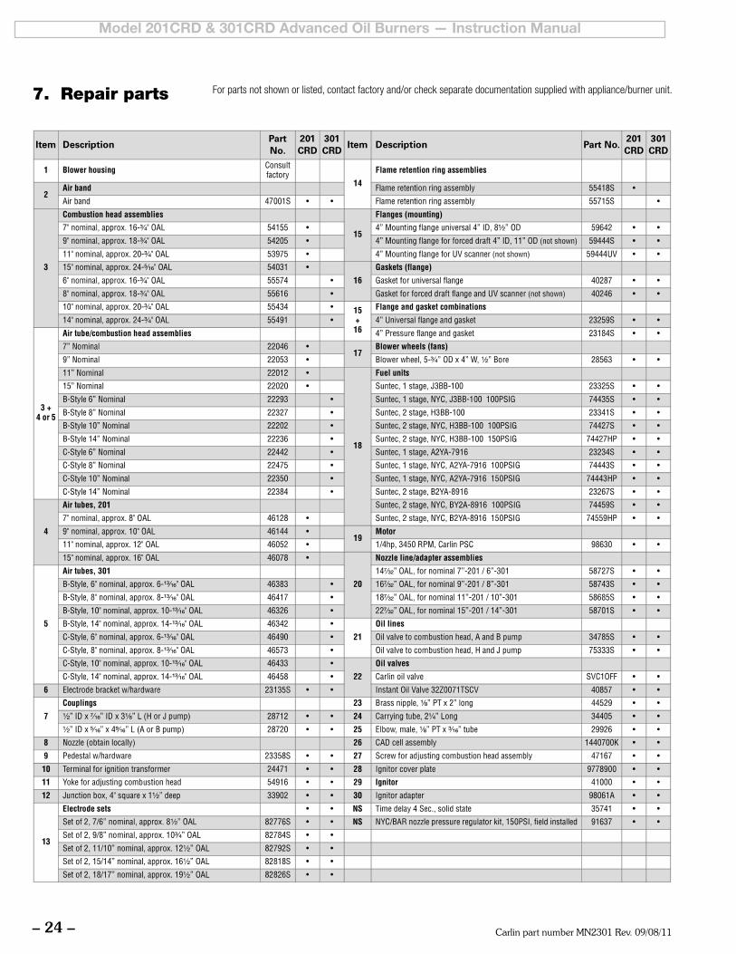
7. Repair parts For parts not shown or listed, contact factory and/or check separate documentation supplied with appliance/burner unit.
Carlin part number MN2301 Rev. 09/08/11 – 25 –
Model 201CRD & 301CRD Advanced Oil Burners — Instruction Manual
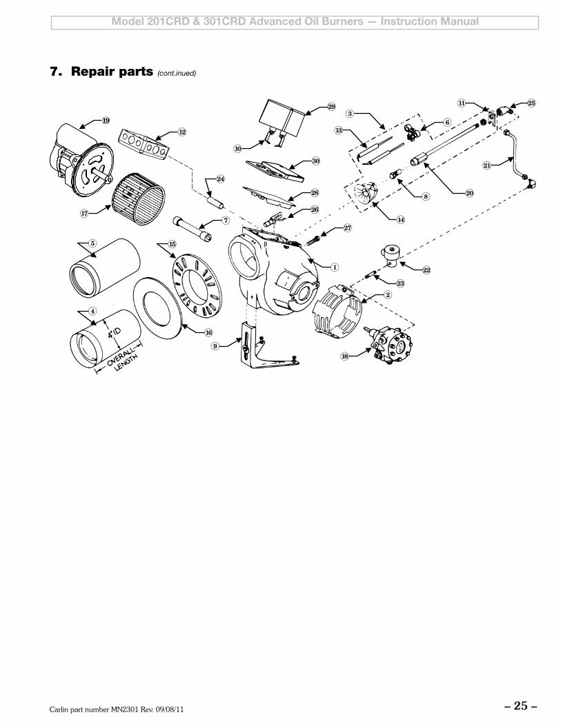
7. Repair parts (cont.inued)
Carlin part number MN2301 Rev. 09/08/11– 26 –
Model 201CRD & 301CRD Advanced Oil Burners — Instruction Manual
8. Maintenance/service procedures
Turn off power to appliance when servicing burner. Failure to comply could result in severe personal injury, death or substantial property damage.
Cleaning blower wheel1. Theblowerwheelaccumulatesdustanddebrisfromnormaloperation.Youwill
needtocleanthewheelbladesperiodicallytopreventreductioninairflow.
• Inspecttheblowerwheelbyremovingtheblowerwheelaccesscover.• Toremovethecover,opentheignitorplateandloosentheblowerwheel
access cover screw about three turns.• Inspecttheblowerwheeltoseeifitneedstobecleaned.Dirtandlinton
thewheelreduceairflow,andmustberemovediftheburneristooperatecorrectly.
2. To clean blades, remove the two bolts securing the motor to blower housing.
a. Slide the motor out and rotate to remove and access blower wheel.b. Use a brush and vacuum to clean each blade and the blower housing
interior.c. Install motor/wheel in blower housing and secure with the two bolts.d. Push wire slack back into junction box.
Replacing blower motor or wheel1. If either the blower wheel or motor must be replaced, remove the two bolts
securing the motor to housing.
2. Disconnectthemotorwiresintheburnerjunctionbox.
3. LoosentheAllenscrewsecuringtheblowertothemotorshaftandremovethewheel.
4. When assembling the replacement assembly, slide the wheel onto the motor shaft and use feeler gauges to set space between the blower wheel and the motor face. This space must be:
201CRD–1/8”301CRD–1/8”
5. Install themotor/wheelassembly in thehousing,wire themotor leadsandsecure the motor with the two bolts.
Motor maintenance• TheCarlinPSCmotor isconstructedwithpermanently-lubricatedbearings,
and requires no oiling. Should you replace the original motor with another type of motor, occasional oiling may be required, depending on motor design and manufacturer’s recommendations.
• Anytimeyoureplaceacomponentordisassembleanypartoftheburnerforservice/maintenance, perform a complete operational test after reassembly to verify the burner operates correctly. Failure to verify operation could result in severe personal injury, death or substantial property damage.
Checking motor windings (98630 PSC motor)1. Allowthemotortocooltoroomtemperature.
2. Remove power from the burner.
3. Disconnecttheorangeandwhitemotorleadsintheburnerjunctionbox.
4. Remove themotorcapacitorcover.Disconnect theblueandwhite leadwiresconnectedtothecapacitor.(Thecapacitoris16microfarads.)
5. Usetheohmmetertocheckeachofthefollowingresistancesbyconnectingto the motor lead wires. If any of the measured resistances is outside of the range listed, the motor winding(s) are faulty and the motor should be replaced.
• OrangetoBlue(capacitor)wire ............................ 5to7ohms
• OrangetoWhite(capacitor)wire .......................... 2 to 4 ohms
• WhitetoBlue(capacitor)wire .............................. 8 to 11 ohms
• WhitemotorwiretoWhitecapacitorwire .............. LESSTHAN1ohm
6. Restorewiringandcomponents.
Checking ignitor Never test an ignitor by placing a screwdriver (or other metallic
object)acrossthehighvoltageclips.Check40700&40900ignitorsonly by observing spark at appliance ignition electrodes, with fuel supplyOFF.Usinganyothermethodcouldcauseignitordamageand severe personal injury.
1. Checking 41000 ignitors only:
• Disconnectelectricalpowertoburner.• Removeholddownclipsorscrews.Liftignitormountingplatetothefull-
openposition.Sethighvoltageclipstoa½”to¾”gap.• Carefullyenergizeignitorandcheckforsparkarcingatthehighvoltage
terminals. If spark jumps the gap, ignitor is good.
Ceramic fiber materials
The appliance may contain ceramic fiber and/or fiberglass materials. Ceramic fiber materials, such as chamber liners, may contain carcinogenic particles (chrystobalites) after exposure to heat.Airborne particles from fiberglass or ceramic fibercomponents have been listed as potentially carcinogenic by the State of California. Take the following precautions when removing, replacing and handling these items.
Avoidbreathingdustandavoidcontactwithskinoreyes.Wearlong-sleeved, loose-fitting clothing, gloves and eye protection. Use aNIOSHN95 certified respirator.This respiratormeetsrequirements for protection from chrystobalites.Actual jobrequirementsorNIOSHregulationsmayrequireotherorad-ditionalprotection.Forinformation,refertotheNIOSHwebsite,http://www.cdc.gov/niosh/homepage.html.
Ceramic fiber removal: To prevent airborne dust, thoroughly wet ceramic fiber with water before handling. Place ceramic fiber materials in a plastic bag and seal to dispose.
Avoidblowing,tearing,sawingorsprayingfiberglassorceramicfiber materials. If such operations are necessary, wear extra protection to prevent breathing dust.
Wash work clothes separately from other laundry. Rinse clothes washer thoroughly afterwards to prevent contamination of other clothing.
NIOSHFirstaidprocedures:
Eye exposure — irrigate immediately
Breathing—freshair.
Carlin part number MN2301 Rev. 09/08/11 – 27 –
Model 201CRD & 301CRD Advanced Oil Burners — Instruction Manual
Limited Warranty
Carlin Combustion Technology, Inc. (Carlin) warrants its products, to the original purchaser, to be free from defects in material and workmanship, under normal use and service for 36 months from the date of manufacture, except for commercial Products (over 3 GPH) that are warranted for 12 months from the date of manufacture; and except for EZ-Pro™ Burners that are warranted for 36 months from the date of manufacture, plus an extended period of two (2) additional years (total of five (5) years).
This warranty does not extend to equipment subjected to misuse, neglect, accident or water damage; nor does this warranty apply unless the product covered by it is properly installed by a qualified, competent technician, who is licensed where state or local codes require, and who is experienced in making such installations, in accordance with NFPA No. 31 of the National Fire Protection Associa-tion and in accordance with all applicable local, state and national codes. Parts that are defective in material or workmanship and within the warranty period will be repaired or replaced as follows:1. Motors, fuel units, transformers and other non-Carlin products should be sent for repair or replace-
ment to an authorized service point or distributor of the manufacturer of such components when reasonably available in the Customer’s locality.
2. Where such local service is not available with respect to the above listed components, or where Carlin components are involved, or for component parts of EZ-Pro Burners that fall within the extended warranty period, such defective parts should be returned, freight prepaid to Carlin. The repaired component or replacement part will be provided to the Customer freight prepaid by Carlin unless the returned part is determined by Carlin to be out of warranty or not to be defective, in which case it will be provided to the customer F.O.B., Carlin, East Longmeadow, Massachusetts.
3. Contact Carlin Customer Service for warranty return procedures.4. The return of a burner is not covered by this warranty. Contact Carlin Tech Service for assistance
before replacing any burner.5. Carlin is not responsible for any labor cost for removal and replacement of equipment.6. Equipment that is repaired or replaced will carry the unexpired portion of the original equipment
warranty.7. If inspection by Carlin does not disclose any defect covered by this warranty, the equipment may
be repaired or replaced at the expense of the Customer, and Carlin’s regular charges will apply.8. Non-Carlin components are warranted for 12 months from date of installation or 18 months from
date of manufacture, whichever date occurs first.
This warranty is limited to the precise terms set forth above, and provides exclusive remedies ex-pressly in lieu of all other remedies and in particular there shall be excluded the implied warranties of merchantability and fitness for a particular purpose. In no event will Carlin Combustion Technology, Inc. be liable for any incidental or consequential damage of any nature. Carlin neither assumes nor authorizes any person to assume for Carlin any other liability or obligations in connection with the sale of this equipment. Carlin’s liability and Customer’s exclusive remedy being limited to repairs or replacement as set forth above.
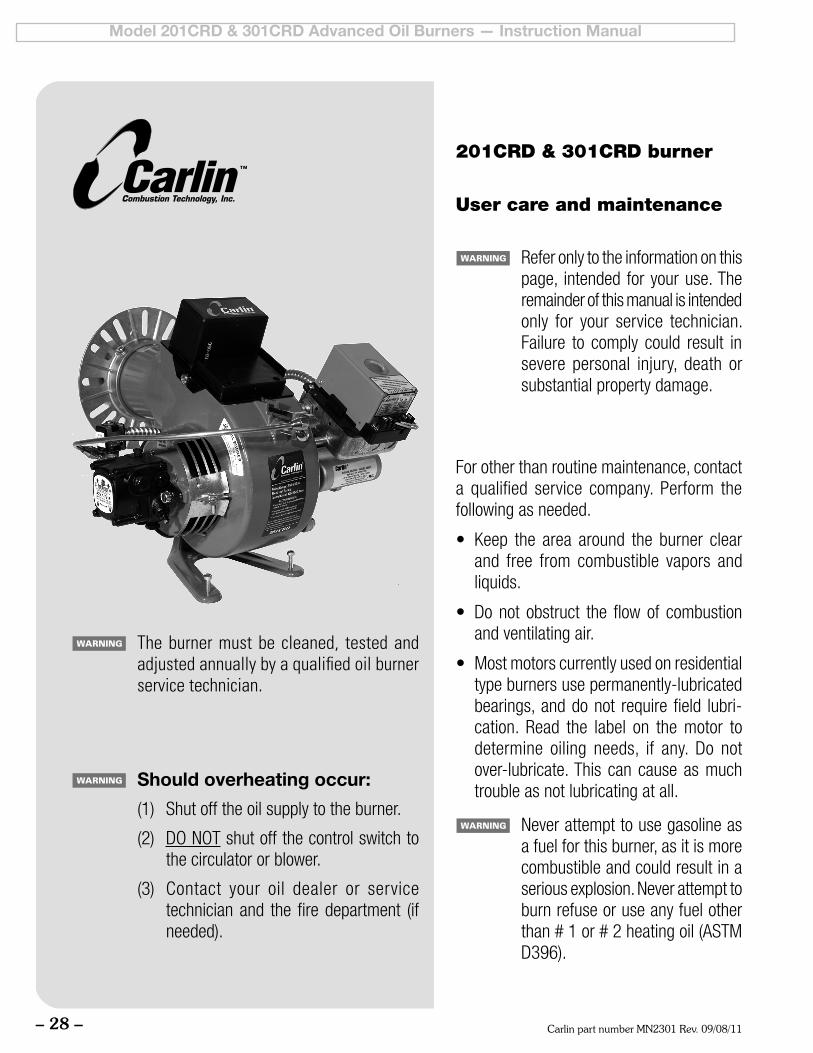
Carlin part number MN2301 Rev. 09/08/11– 28 –
Model 201CRD & 301CRD Advanced Oil Burners — Instruction Manual
For other than routine maintenance, contact a qualified service company. Perform the following as needed.
• Keep the area around the burner clearand free from combustible vapors and liquids.
• Donot obstruct the flowof combustionand ventilating air.
• Mostmotorscurrentlyusedonresidentialtype burners use permanently-lubricated bearings, and do not require field lubri-cation. Read the label on the motor to determine oiling needs, if any. Do notover-lubricate. This can cause as much trouble as not lubricating at all.
Never attempt to use gasoline as a fuel for this burner, as it is more combustible and could result in a serious explosion. Never attempt to burn refuse or use any fuel other than#1or#2heatingoil(ASTMD396).
201CRD & 301CRD burner
User care and maintenance
Refer only to the information on this page, intended for your use. The remainder of this manual is intended only for your service technician. Failure to comply could result in severe personal injury, death or substantial property damage.
Should overheating occur:
(1) Shut off the oil supply to the burner.
(2) DONOT shut off the control switch to the circulator or blower.
(3) Contact your oil dealer or servicetechnician and the fire department (if needed).
The burner must be cleaned, tested and adjusted annually by a qualified oil burner service technician.
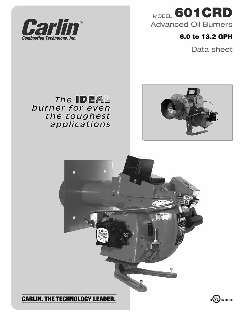
MODEL 601CRDAdvanced Oil Burners
Data sheet
6.0 to 13.2 GPH
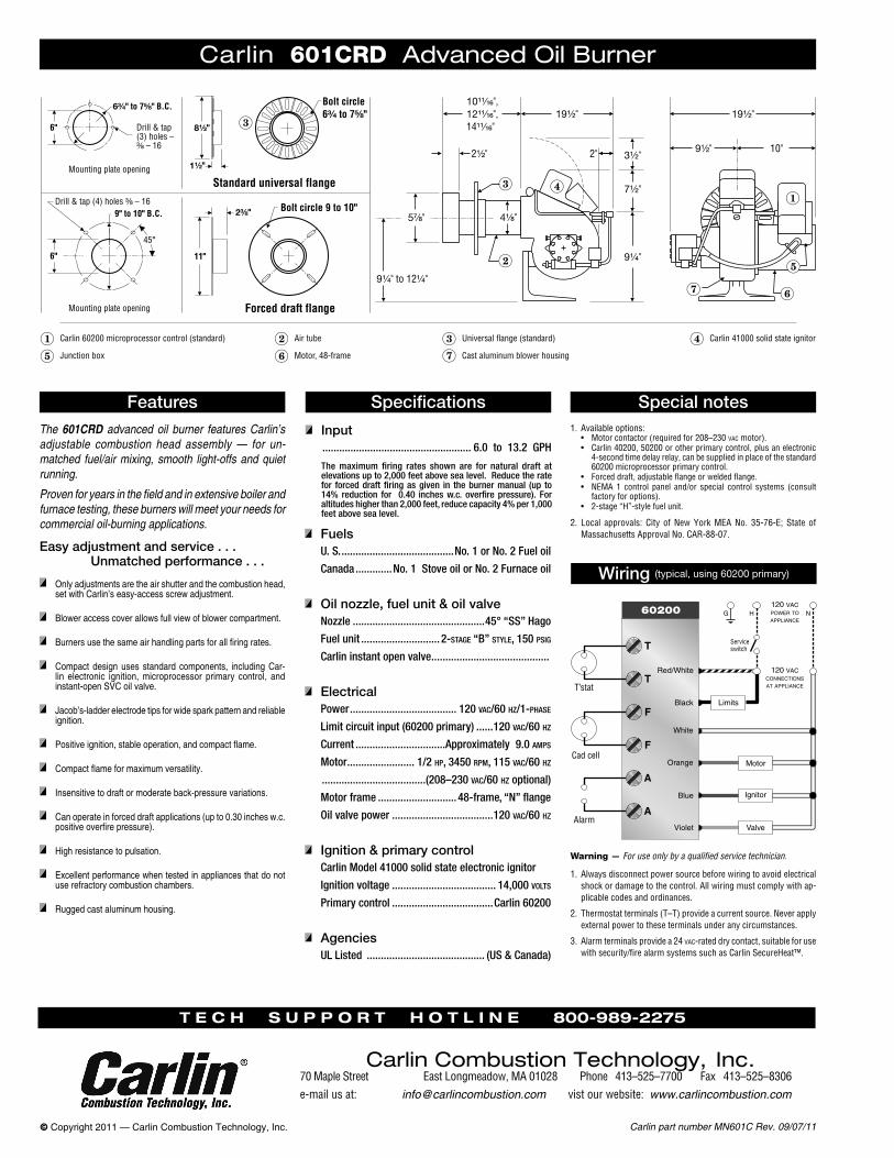
Carlin part number MN601C Rev. 09/07/11© Copyright 2011 — Carlin Combustion Technology, Inc.
The 601CRD advanced oil burner features Carlin’s adjustable combustion head assembly — for un-matched fuel/air mixing, smooth light-offs and quiet running.
Proven for years in the field and in extensive boiler and furnace testing, these burners will meet your needs for commercial oil-burning applications.
Carlin 601CRD Advanced Oil Burner
Features Specifications
Input ..................................................... 6.0 to 13.2 GPH
The maximum firing rates shown are for natural draft at elevations up to 2,000 feet above sea level. Reduce the rate for forced draft firing as given in the burner manual (up to 14% reduction for 0.40 inches w.c. overfire pressure). For altitudes higher than 2,000 feet, reduce capacity 4% per 1,000 feet above sea level.
Special notes
Wiring (typical, using 60200 primary)
Warning — For use only by a qualified service technician.
1. Always disconnect power source before wiring to avoid electrical shock or damage to the control. All wiring must comply with ap-plicable codes and ordinances.
2. Thermostat terminals (T–T) provide a current source. Never apply external power to these terminals under any circumstances.
3. Alarm terminals provide a 24 vac-rated dry contact, suitable for use with security/fire alarm systems such as Carlin SecureHeat™.
Easy adjustment and service . . . Unmatched performance . . .
Only adjustments are the air shutter and the combustion head, set with Carlin’s easy-access screw adjustment.
Blower access cover allows full view of blower compartment.
Burnersusethesameairhandlingpartsforallfiringrates.
Compact design uses standard components, including Car-lin electronic ignition, microprocessor primary control, and instant-open SVC oil valve.
Jacob’s-ladder electrode tips for wide spark pattern and reliable ignition.
Positiveignition,stableoperation,andcompactflame.
Compactflameformaximumversatility.
Insensitive to draft or moderate back-pressure variations.
Can operate in forced draft applications (up to 0.30 inches w.c. positiveoverfirepressure).
High resistance to pulsation.
Excellentperformancewhentestedinappliancesthatdonotuse refractory combustion chambers.
Rugged cast aluminum housing.
1. Available options:• Motor contactor (required for 208–230 vac motor).• Carlin 40200, 50200 or other primary control, plus an electronic
4-second time delay relay, can be supplied in place of the standard 60200 microprocessor primary control.
• Forced draft, adjustable flange or welded flange.• NEMA 1 control panel and/or special control systems (consult
factory for options).• 2-stage “H”-style fuel unit.
2. Local approvals: City of New York MEA No. 35-76-E; State of Massachusetts Approval No. CAR-88-07. Fuels
U. S. ........................................No. 1 or No. 2 Fuel oil
Canada .............No. 1 Stove oil or No. 2 Furnace oil
Oil nozzle, fuel unit & oil valveNozzle ...............................................45° “SS” Hago
Fuel unit ............................ 2-stage “B” style, 150 psig
Carlin instant open valve ..........................................
ElectricalPower ...................................... 120 vac/60 hz/1-phase
Limit circuit input (60200 primary) ......120 vac/60 hz
Current ................................Approximately 9.0 amps
Motor ........................ 1/2 hp, 3450 rpm, 115 vac/60 hz
.....................................(208–230 vac/60 hz optional)
Motor frame ............................ 48-frame, “N” flange
Oil valve power ....................................120 vac/60 hz
Ignition & primary controlCarlin Model 41000 solid state electronic ignitor
Ignition voltage ..................................... 14,000 volts
Primary control ....................................Carlin 60200
AgenciesUL Listed .......................................... (US & Canada)
T e c h s u p p o r T h o T l i n e 800-989-2275
Carlin Combustion Technology, Inc.70 Maple Street East Longmeadow, MA 01028 Phone 413–525–7700 Fax 413–525–8306e-mail us at: [email protected] vist our website: www.carlincombustion.com
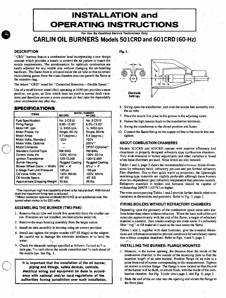
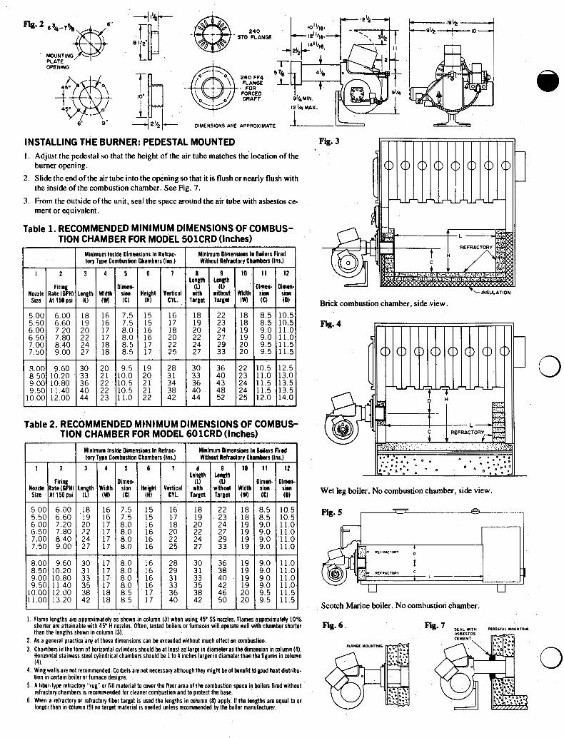
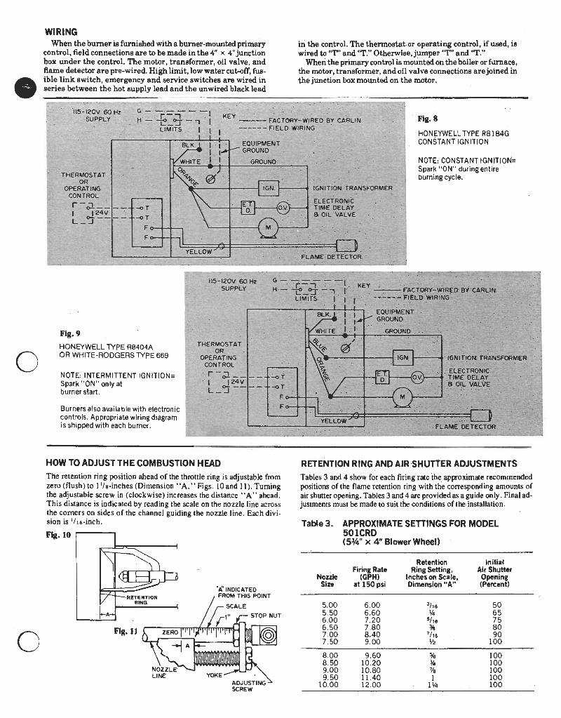
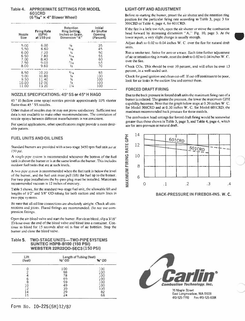
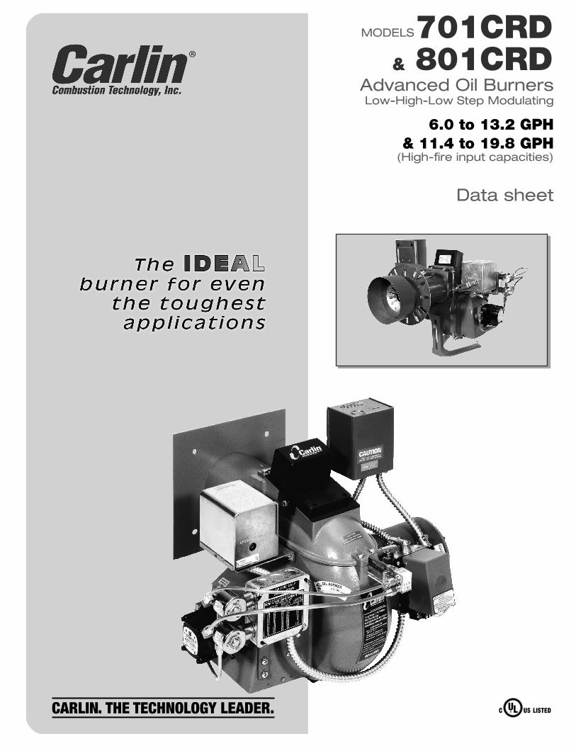
MODELS701CRD& 801CRD
Advanced Oil BurnersLow-High-Low Step Modulating
Data sheet
6.0 to 13.2 GPH& 11.4 to 19.8 GPH
(High-fire input capacities)
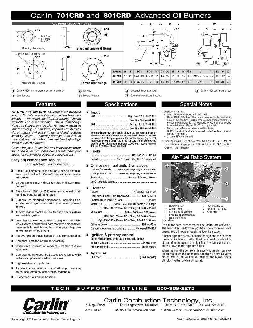
Carlin part number MN7801C Rev. 09/07/11© Copyright 2011 — Carlin Combustion Technology, Inc.
701CRD and 801CRD advanced oil burners feature Carlin’s adjustable combustion head as-sembly — for unmatched fuel/air mixing, smooth light-offs and quiet running. The automatically-closed air damper and low-high-low step modulation (approximately 2:1 turndown) improve efficiency by closer matching of output to demand and reduced stand-by losses — typically savings of 15-20% in seasonal fuel usage when compared to single-stage flame retention burners.
Proven for years in the field and in extensive boiler and furnace testing, these burners will meet your needs for commercial oil-burning applications.
Carlin 701CRD and 801CRD Advanced Oil Burners
Features Specifications
Input701 ............................................ High fire: 6.0 to 13.2 GPH ....................................................... Low fire: 3.6 to 6.6 GPH 801 .............................................High fire: 11.4 to 19.8 GPH ....................................................... Low fire: 6.6 to 8.4 GPH
The maximum high-fire inputs shown are for natural draft at elevations up to 2,000 feet above sea level. Reduce the rate for forced draft firing as given in the burner manual (up to 18% reduction for 701 or up to 10% for 801 at 0.50 inches w.c. overfire pressure). For altitudes higher than 2,000 feet, reduce capacity 4% per 1,000 feet above sea level.
Special Notes
Air-Fuel Ratio SystemEasy adjustment and service . . . Unmatched performance . . .
Simple adjustments of the air shutter and combus-tion head, set with Carlin’s easy-access screw adjustment.
Blower access cover allows full view of blower com-partment.
Each burner (701 or 801) uses a single set of air handling parts for all firing rates.
Burners use standard components, including Car-lin electronic ignitor and microprocessor primary control.
Jacob’s-ladder electrode tips for wide spark pattern and reliable ignition.
Low-high-low step modulation, using low- and high-fire oil valves and nozzles, with motorized air damper. Low-fire hold switch standard. (Requires high fire control on boiler, by others.)
Positive ignition, stable operation, and compact flame.
Compact flame for maximum versatility.
Insensitive to draft or moderate back-pressure variations.
Can operate in forced draft applications (up to 0.60 inches w.c. positive overfire pressure).
High resistance to pulsation.
Excellent performance when tested in appliances that do not use refractory combustion chambers.
Rugged cast aluminum housing.
1. Available options:• Alternatemotorvoltages,aslistedatleft.• Carlin40200,50200orotherprimarycontrolcanbesuppliedin
placeofthestandard60200microprocessorprimarycontrol.UVsensorisavailablefor801.Anelectronic4-secondtimedelayrelayisincludedwhen40200or50200primaryisused.
• Forceddraft,adjustableflangeorweldedflange.• NEMA1 control panel and/or special control systems (consult
factoryforoptions).• 2-stage“H”-stylefuelunit.
2. Local approvals: City ofNewYorkMEANo. 35-76-E; State ofMassachusetts ApprovalNo. CAR-88-08 for 701CRD andNo.CAR-88-10for801CRD.
FuelsU. S. ................................................... No. 1 or No. 2 Fuel oilCanada ........................ No. 1 Stove oil or No. 2 Furnace oil
Oil nozzles, fuel units & oil valves(1) Low fire nozzle ........ Patterm and angle vary with application
(1) High fire nozzle ....... Patterm and angle vary with application
Fuel unit ........................................2-stage “B” style, 150 psig
(2) Oil solenoid valves ..........................................................
ElectricalPower ..............................................120vac/60hz/1-phase
Limit circuit input (60200 primary).................. 120 vac/60 hz
Control circuit load (120 vac) ................................... 1.2 amps
Motor, 701 ............... 1/2 hp, 3450 rpm, 48-frame, “N” flange ................. 115 / 208–230 vac/60 hz/1-ph, 8.4 / 3.8–4.2 amps
Motor, 801 ................................3/4 hp, 3450 rpm, 56C-frame ................. 115 / 208–230 vac/60 hz/1-ph, 9.8 / 4.8–4.9 amps
..........Opt: 208–230 / 460 vac/60 hz/3-ph, 3.0–3.2 / 1.6 amps
Oil valve power ................................................ 120 vac/60 hz
Damper motor (with end switch) .................Honeywell M436A
Ignition & primary controlCarlin Model 41000 solid state electronic ignitorIgnition voltage ..................................................14,000 volts
Primary control................................................ Carlin 60200
AgenciesUL Listed ......................................................(US & Canada)
1 Dampermotor2 Actuatorarm3 Low-fireairadjustment4 Linkageandcounterweight5 High-fireoilvalve
6 Low-fireoilvalve7 Fuelunit(150PSIG)8 Airshutter
OperationOncallforheat,burnermotorandignitorareactivated.Theairshutterisinlow-fireposition.Thelow-fireoilvalveopens,andoilflowsthroughthelow-firenozzle.Ifboilerhigh-firecontrollercallsforhighfire,thedampermotorbeginstoopen.Whenthedampermotorendswitchcloses(damperopen),thehigh-fireoilvalveisactivated,andoilflowstothehigh-firenozzle.Whenthehigh-firecontrollerissatisfied,thedampermo-torclosesdowntheairshutterandthehigh-fireoilvalvecloses.Whencallforheat issatisfied,theburnershutsoff(closingthelow-fireoilvalve).
T e c h s u p p o r T h o T l i n e 800-989-2275
Carlin Combustion Technology, Inc.70MapleStreet EastLongmeadow,MA01028 Phone413–525–7700Fax413–525–8306e-mailusat: [email protected] vistourwebsite:www.carlincombustion.com
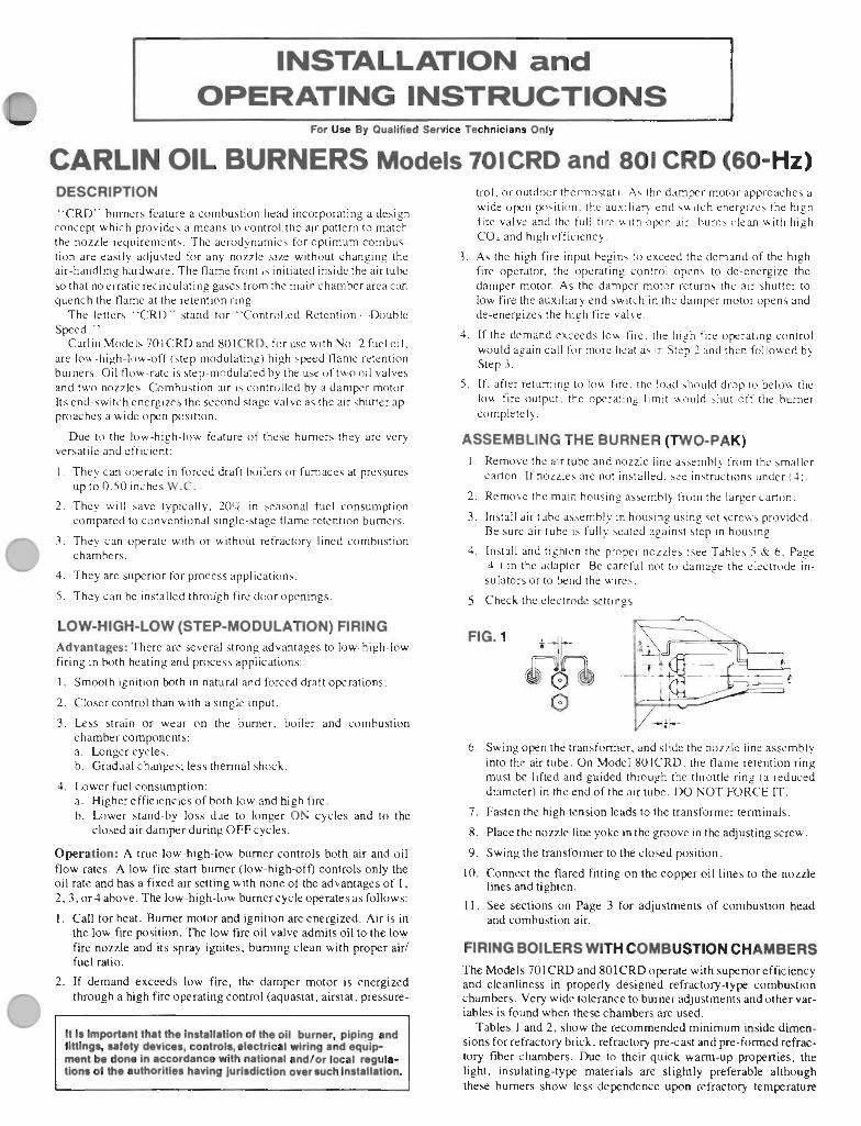
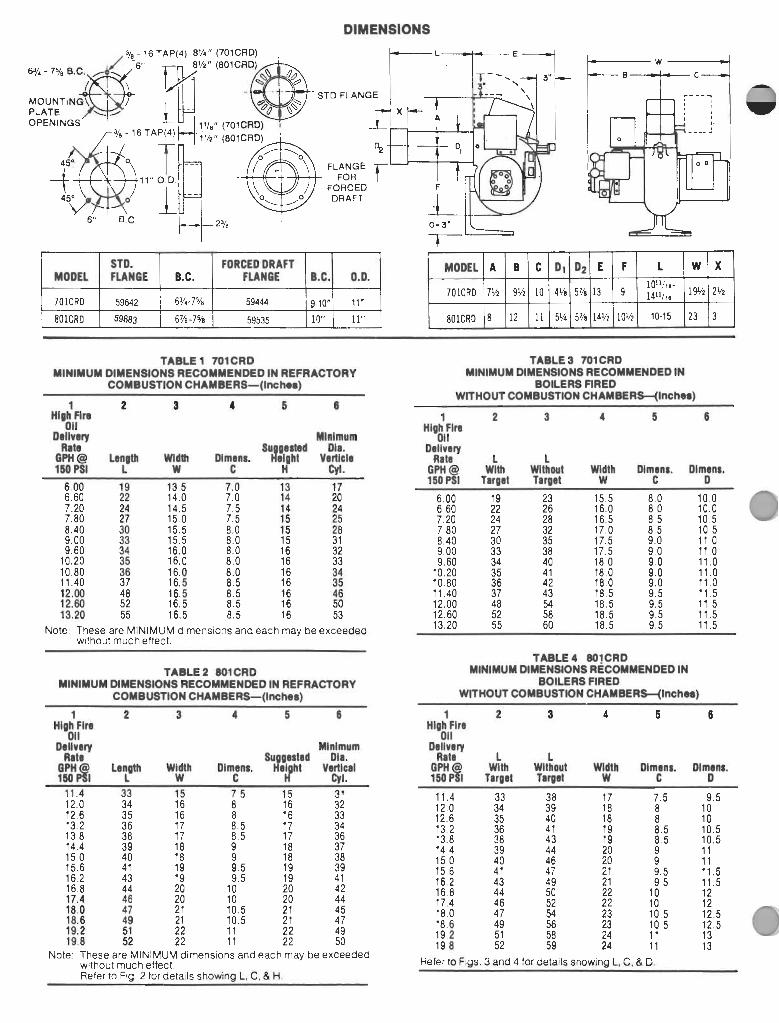
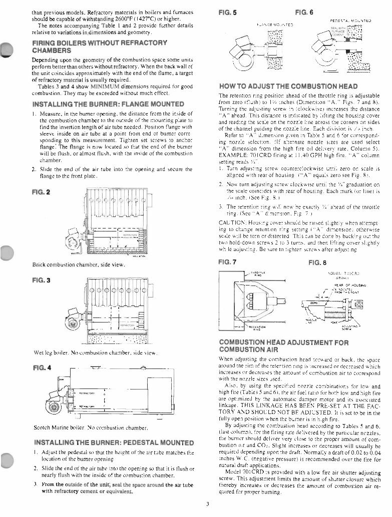
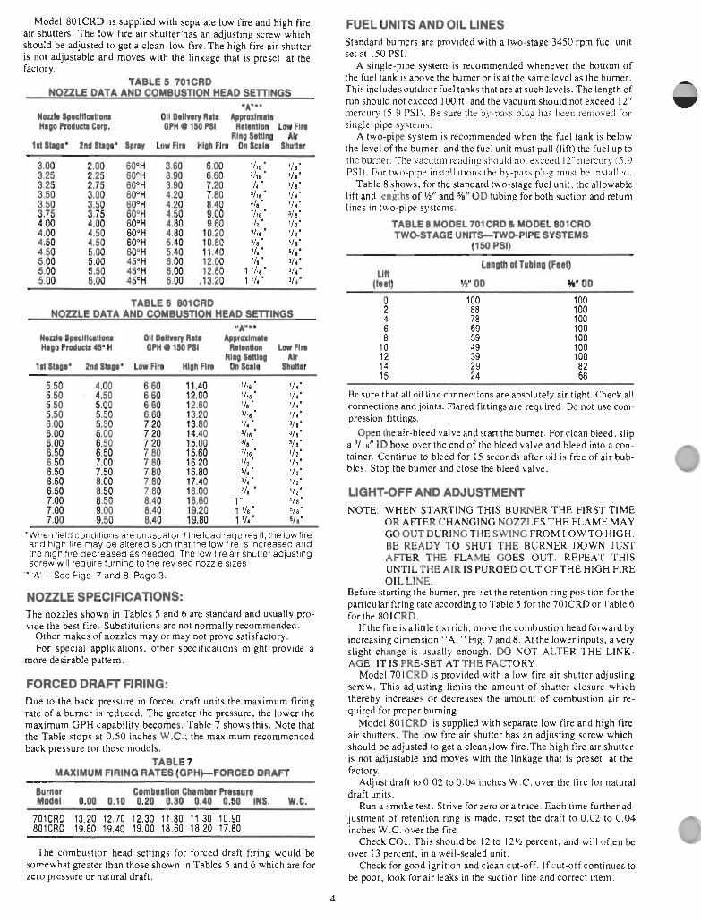
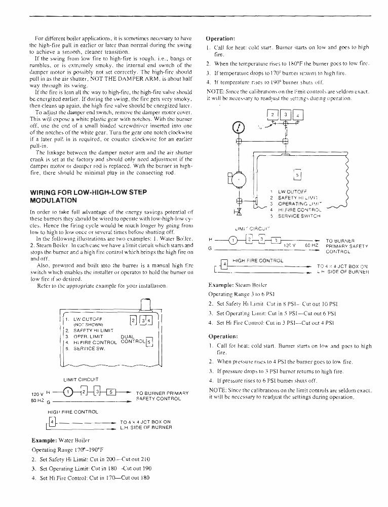

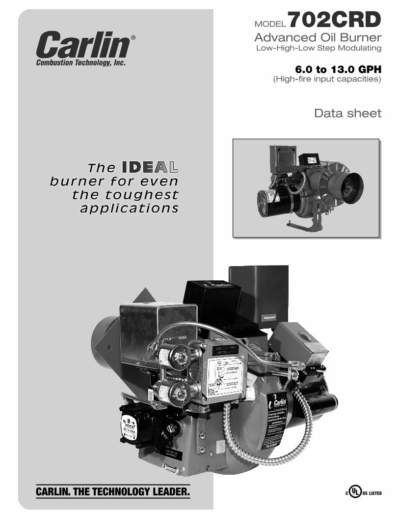
MODEL702CRDAdvanced Oil BurnerLow-High-Low Step Modulating
Data sheet
6.0 to 13.0 GPH(High-fire input capacities)
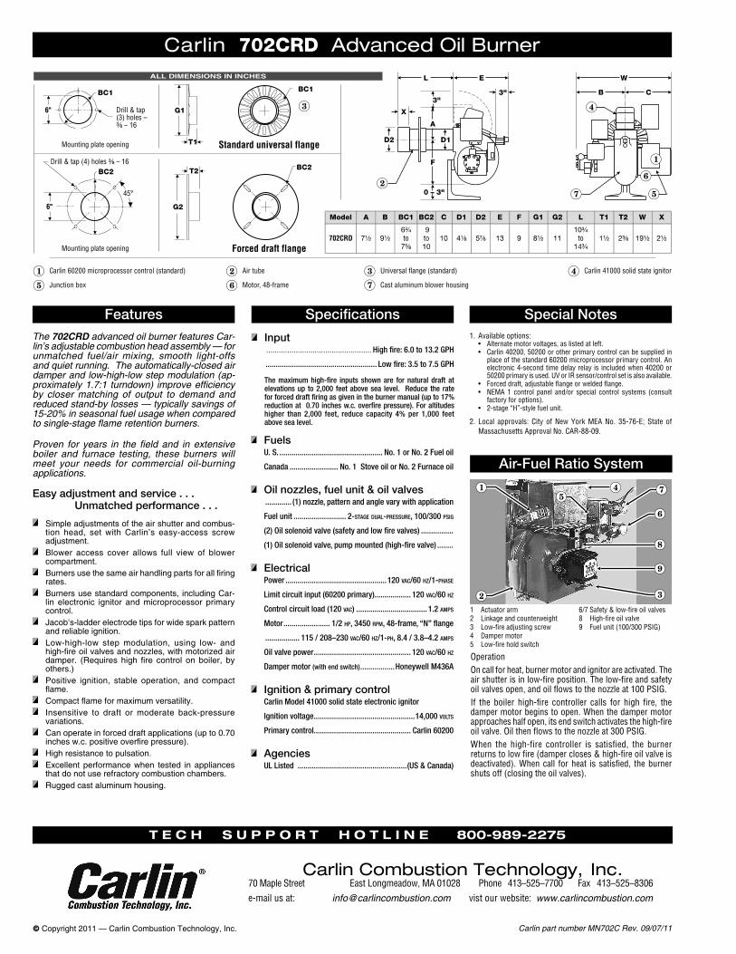
Carlin part number MN702C Rev. 09/07/11© Copyright 2011 — Carlin Combustion Technology, Inc.
The 702CRD advanced oil burner features Car-lin’s adjustable combustion head assembly — for unmatched fuel/air mixing, smooth light-offs and quiet running. The automatically-closed air damper and low-high-low step modulation (ap-proximately 1.7:1 turndown) improve efficiency by closer matching of output to demand and reduced stand-by losses — typically savings of 15-20% in seasonal fuel usage when compared to single-stage flame retention burners.
Proven for years in the field and in extensive boiler and furnace testing, these burners will meet your needs for commercial oil-burning applications.
Carlin 702CRD Advanced Oil Burner
Features Specifications
Input .................................................. High fire: 6.0 to 13.2 GPH
....................................................... Low fire: 3.5 to 7.5 GPH
The maximum high-fire inputs shown are for natural draft at elevations up to 2,000 feet above sea level. Reduce the rate for forced draft firing as given in the burner manual (up to 17% reduction at 0.70 inches w.c. overfire pressure). For altitudes higher than 2,000 feet, reduce capacity 4% per 1,000 feet above sea level.
Special Notes
Air-Fuel Ratio System
Easy adjustment and service . . . Unmatched performance . . .
Simple adjustments of the air shutter and combus-tion head, set with Carlin’s easy-access screw adjustment.
Blower access cover allows full view of blower compartment.
Burnersusethesameairhandlingpartsforallfiringrates.
Burners use standard components, including Car-lin electronic ignitor and microprocessor primary control.
Jacob’s-ladder electrode tips for wide spark pattern and reliable ignition.
Low-high-low step modulation, using low- and high-fireoilvalvesandnozzles,withmotorizedairdamper. (Requires high fire control on boiler, byothers.)
Positive ignition, stable operation, and compact flame.
Compactflameformaximumversatility. Insensitive to draft or moderate back-pressure
variations. Can operate in forced draft applications (up to 0.70 inchesw.c.positiveoverfirepressure).
High resistance to pulsation. Excellent performancewhen tested in appliances
that do not use refractory combustion chambers. Rugged cast aluminum housing.
1. Available options:• Alternatemotorvoltages,aslistedatleft.• Carlin40200,50200orotherprimarycontrolcanbesuppliedin
placeofthestandard60200microprocessorprimarycontrol.Anelectronic4-secondtimedelayrelay is includedwhen40200or50200primaryisused.UVorIRsensor/controlsetisalsoavailable.
• Forceddraft,adjustableflangeorweldedflange.• NEMA1 control panel and/or special control systems (consult
factoryforoptions).• 2-stage“H”-stylefuelunit.
2. Local approvals: City ofNewYorkMEANo. 35-76-E; State ofMassachusettsApprovalNo.CAR-88-09.
FuelsU. S. ................................................... No. 1 or No. 2 Fuel oil
Canada ........................ No. 1 Stove oil or No. 2 Furnace oil
Oil nozzles, fuel unit & oil valves ............. (1) nozzle, pattern and angle vary with application
Fuel unit .......................... 2-stage dual-pressure, 100/300 psig
(2) Oil solenoid valve (safety and low fire valves) ................
(1) Oil solenoid valve, pump mounted (high-fire valve) ........
ElectricalPower ..................................................120 vac/60 hz/1-phase
Limit circuit input (60200 primary).................. 120 vac/60 hz
Control circuit load (120 vac) ................................... 1.2 amps
Motor ....................... 1/2 hp, 3450 rpm, 48-frame, “N” flange
................. 115 / 208–230 vac/60 hz/1-ph, 8.4 / 3.8–4.2 amps
Oil valve power ................................................ 120 vac/60 hz
Damper motor (with end switch) .................Honeywell M436A
Ignition & primary controlCarlin Model 41000 solid state electronic ignitor
Ignition voltage ..................................................14,000 volts
Primary control................................................ Carlin 60200
AgenciesUL Listed ......................................................(US & Canada)
1 Actuatorarm2 Linkageandcounterweight3 Low-fireadjustingscrew4 Dampermotor5 Low-fireholdswitch
6/7Safety&low-fireoilvalves8 High-fireoilvalve9 Fuelunit(100/300PSIG)
OperationOncallforheat,burnermotorandignitorareactivated.Theairshutterisinlow-fireposition.Thelow-fireandsafetyoilvalvesopen,andoilflowstothenozzleat100PSIG.If the boiler high-fire controller calls for high fire, thedampermotorbeginstoopen.Whenthedampermotorapproacheshalfopen,itsendswitchactivatesthehigh-fireoilvalve.Oilthenflowstothenozzleat300PSIG.When the high-fire controller is satisfied, the burnerreturnstolowfire(dampercloses&high-fireoilvalveisdeactivated).Whencall forheat issatisfied, theburnershutsoff(closingtheoilvalves).
T e c h s u p p o r T h o T l i n e 800-989-2275
Carlin Combustion Technology, Inc.70MapleStreet EastLongmeadow,MA01028 Phone413–525–7700Fax413–525–8306e-mailusat: [email protected] vistourwebsite:www.carlincombustion.com
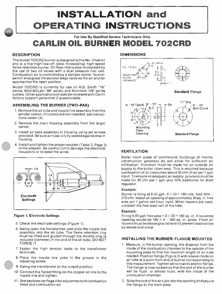
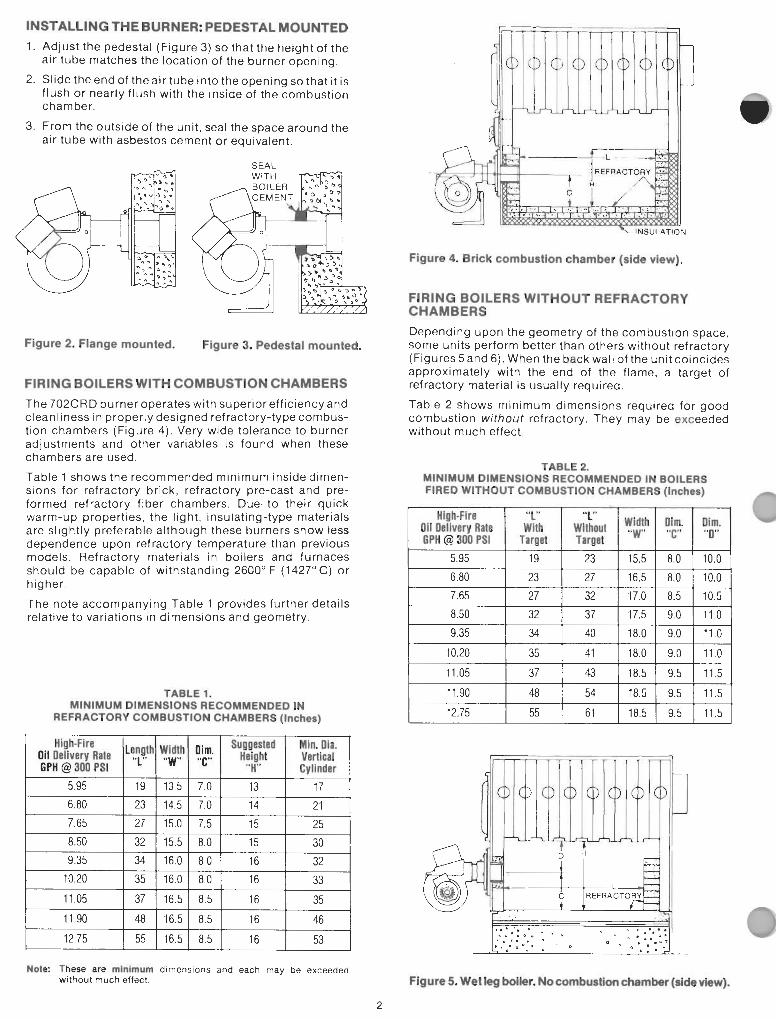
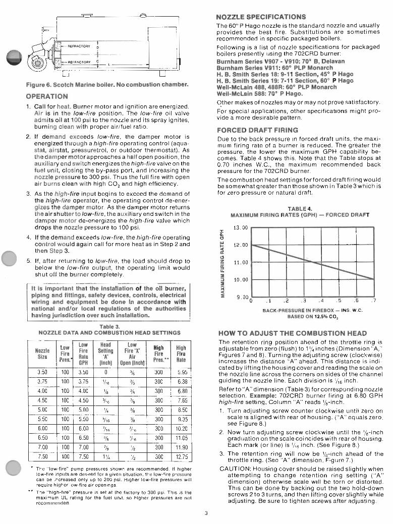
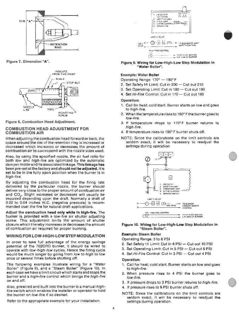
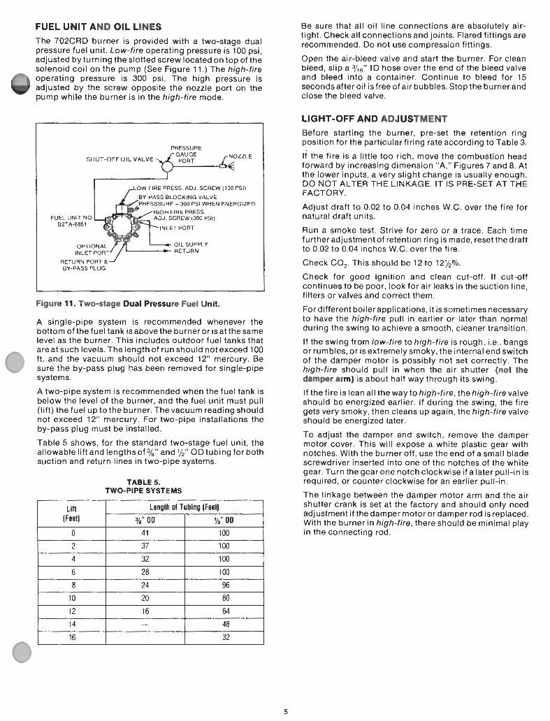

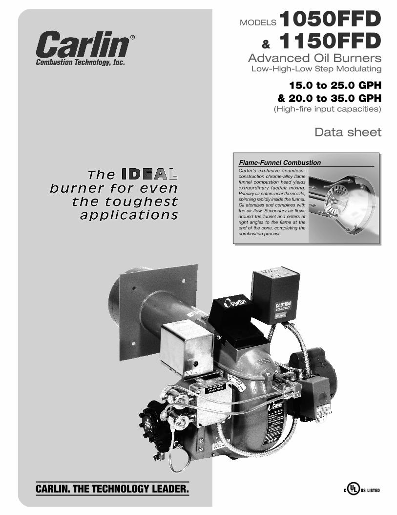
Flame-Funnel CombustionCarlin’s exclusive seamless-construction chrome-alloy flame funnel combustion head yields extraordinary fuel/air mixing. Primary air enters near the nozzle, spinning rapidly inside the funnel. Oil atomizes and combines with the air flow. Secondary air flows around the funnel and enters at right angles to the flame at the end of the cone, completing the combustion process.
MODELS1050FFD& 1150FFD
Advanced Oil BurnersLow-High-Low Step Modulating
Data sheet
15.0 to 25.0 GPH& 20.0 to 35.0 GPH
(High-fire input capacities)
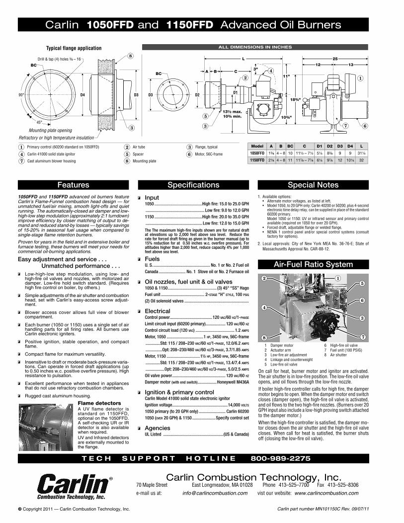
Carlin part number MN101150C Rev. 09/07/11© Copyright 2011 — Carlin Combustion Technology, Inc.
1050FFD and 1150FFD advanced oil burners feature Carlin’s Flame-Funnel combustion head design — for unmatched fuel/air mixing, smooth light-offs and quiet running. The automatically-closed air damper and low-high-low step modulation (approximately 2:1 turndown) improve efficiency by closer matching of output to de-mand and reduced stand-by losses — typically savings of 15-20% in seasonal fuel usage when compared to single-stage flame retention burners.Proven for years in the field and in extensive boiler and furnace testing, these burners will meet your needs for commercial oil-burning applications.
Carlin 1050FFD and 1150FFD Advanced Oil Burners
Features Specifications
Input1050 ...........................................High fire: 15.0 to 25.0 GPH ..................................................... Low fire: 9.0 to 12.0 GPH 1150 ...........................................High fire: 20.0 to 35.0 GPH ................................................... Low fire: 12.0 to 15.0 GPH
The The maximum high-fire inputs shown are for natural draft at elevations up to 2,000 feet above sea level. Reduce the rate for forced draft firing as given in the burner manual (up to 15% reduction for at 0.50 inches w.c. overfire pressure). For altitudes higher than 2,000 feet, reduce capacity 4% per 1,000 feet above sea level.
Special Notes
Air-Fuel Ratio SystemEasy adjustment and service . . .
Unmatched performance . . . Low-high-low step modulation, using low- and
high-fire oil valves and nozzles, with motorized air damper. Low-fire hold switch standard. (Requires high fire control on boiler, by others.)
Simple adjustments of the air shutter and combustion head, set with Carlin’s easy-access screw adjust-ment.
Blower access cover allows full view of blower compartment.
Each burner (1050 or 1150) uses a single set of air handling parts for all firing rates. All burners use Carlin electronic igniters.
Positive ignition, stable operation, and compact flame.
Compact flame for maximum versatility.
Insensitive to draft or moderate back-pressure varia-tions. Can operate in forced draft applications (up to 0.50 inches w.c. positive overfire pressure). High resistance to pulsation.
Excellent performance when tested in appliances that do not use refractory combustion chambers.
Rugged cast aluminum housing.
1. Available options:• Alternatemotorvoltages,aslistedatleft.• Model1050,to20GPHonly:Carlin40200or50200,plus4-second
electronictimedelayrelay,canbesuppliedinplaceofthestandard60200primary.
Model1050or1150:UVorinfraredsensorandprimarycontrolavailable(requiredon1050forover20GPH).
• Forceddraft,adjustableflangeorweldedflange.• NEMA1 control panel and/or special control systems (consult
factoryforoptions).
2. Local approvals: City ofNewYorkMEANo. 36-76-E; State ofMassachusettsApprovalNo.CAR-88-12.
FuelsU. S. ................................................... No. 1 or No. 2 Fuel oilCanada ........................ No. 1 Stove oil or No. 2 Furnace oil
Oil nozzles, fuel unit & oil valves1050 & 1150 ............................................ (3) 45° “SS” HagoFuel unit ....................................... 2-stage “H” style, 100 psig
(2) Oil solenoid valves ..........................................................
ElectricalControl power ......................................120 vac/60 Hz/1-pHase
Limit circuit input (60200 primary).................. 120 vac/60 Hz
Control circuit load (120 vac) ................................... 1.2 amps
Motor, 1050 .................................1 Hp, 3450 rpm, 56C-frame .............Std: 115 / 208–230 vac/60 Hz/1-pHase, 12.0/6.2 amps
...............Opt: 208–230/460 vac/60 Hz/3-pHase, 3.7/1.85 amps
Motor, 1150 ..............................1½ Hp, 3450 rpm, 56C-frame .............Std: 115 / 208–230 vac/60 Hz/1-pHase, 13.4/7.4 amps
.................Opt: 208–230/460 vac/60 Hz/3-pHase, 5.0/2.5 amps
Oil valve power ................................................ 120 vac/60 Hz
Damper motor (with end switch) .................Honeywell M436A
Ignition & primary controlCarlin Model 41000 solid state electronic ignitorIgnition voltage ..................................................14,000 volts
1050 primary (to 20 GPH only) ........................ Carlin 602001050 (over 20 gpH) & 1150 .....................Specify control set
AgenciesUL Listed ......................................................(US & Canada)
1 Dampermotor2 Actuatorarm3 Low-fireairadjustment4 Linkageandcounterweight5 Low-fireoilvalve
6 High-fireoilvalve7 Fuelunit(100PSIG)8 Airshutter
Oncallforheat,burnermotorandignitorareactivated.Theairshutterisinlow-fireposition.Thelow-fireoilvalveopens,andoilflowsthroughthelow-firenozzle.Ifboilerhigh-firecontrollercallsforhighfire,thedampermotorbeginstoopen.Whenthedampermotorendswitchcloses(damperopen),thehigh-fireoilvalveisactivated,andoilflowstothetwohigh-firenozzles.(Burnersover20GPHinputalsoincludealow-highprovingswitchattachedtothedampermotor.)Whenthehigh-firecontrollerissatisfied,thedampermo-torclosesdowntheairshutterandthehigh-fireoilvalvecloses.Whencallforheat issatisfied,theburnershutsoff(closingthelow-fireoilvalve).
Flame detectorsA UV flame detector is standard on 1150FFD, optional on the 1050FFD. A self-checking UR or IR detector is also available when required.UV and Infrared detectors are externally mounted to the flange.
T e c h s u p p o r T h o T l i n e 800-989-2275
Carlin Combustion Technology, Inc.70MapleStreet EastLongmeadow,MA01028 Phone413–525–7700Fax413–525–8306e-mailusat: [email protected] vistourwebsite:www.carlincombustion.com
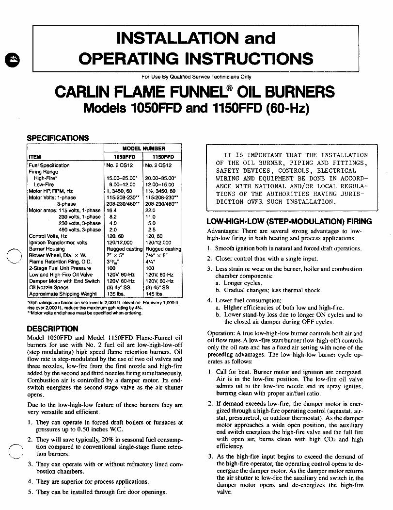
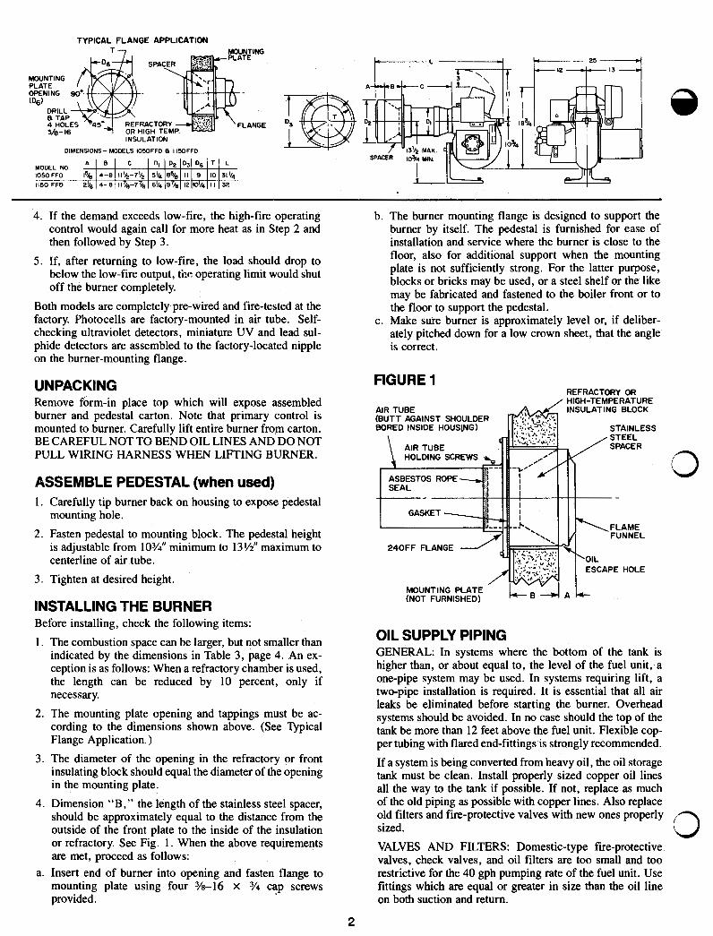
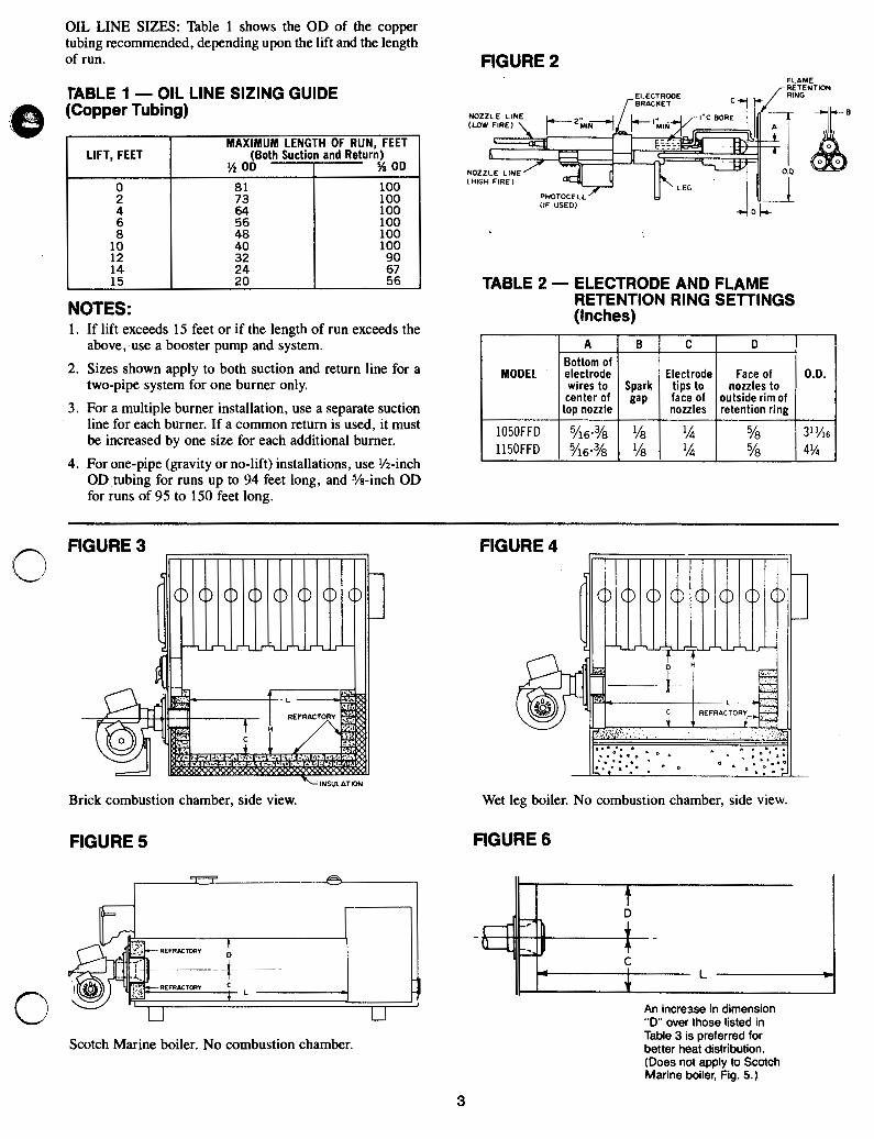
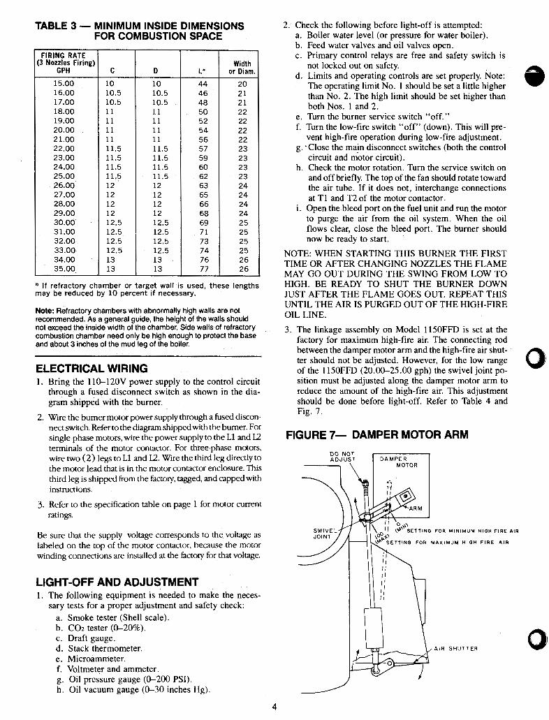
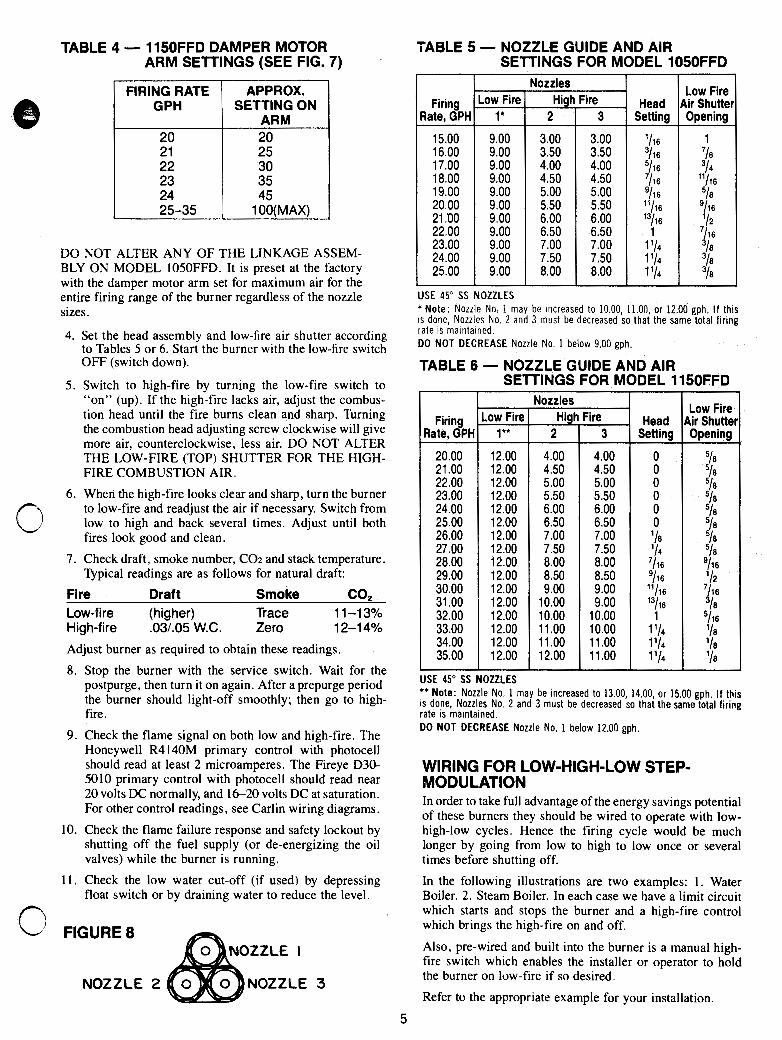
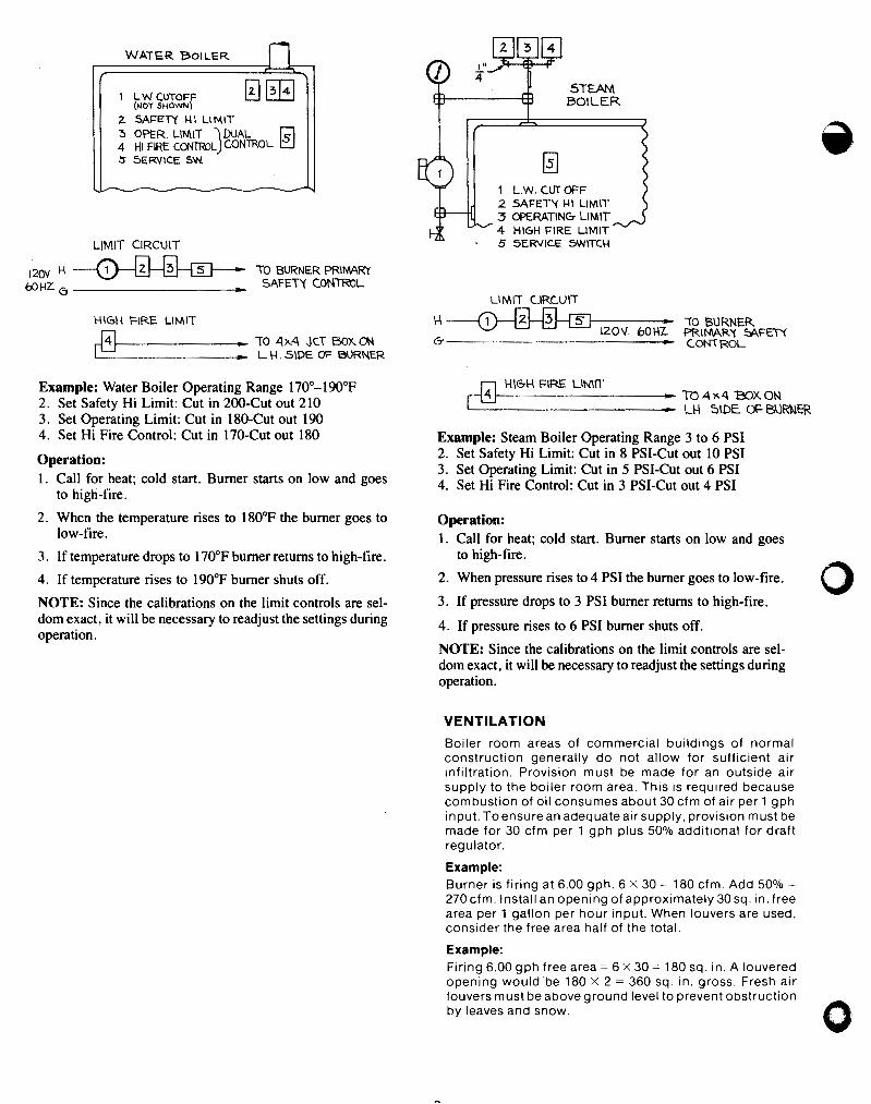


Carlin part number Catalog48 Rev. 09/02/11© Copyright 2011 — Carlin Combustion Technology, Inc.
T e c h s u p p o r T h o T l i n e 800-989-2275
Carlin Combustion Technology, Inc.70 Maple Street East Longmeadow, MA 01028 Phone 413–525–7700 Fax 413–525–8306
e-mail us at: [email protected] vist our website: www.carlincombustion.com