Embed Size (px)
Citation preview
1
Communication Systems
Lecture 7
Dong In Kim
School of Info/Comm Engineering
Sungkyunkwan University
2
Outline
� Expression of SSB signals
� Waveform of SSB signals
� Modulators for SSB:
� Frequency discrimination
� Phase discrimination
� Coherent Detection of SSB

3
Expression of SSB Signals
� The USB signal is:
� Proof:
� It is easier to prove in frequency domain.
� Shifting M(f) to get SSB:
f
M(f)
fUSB(f) fc-fc
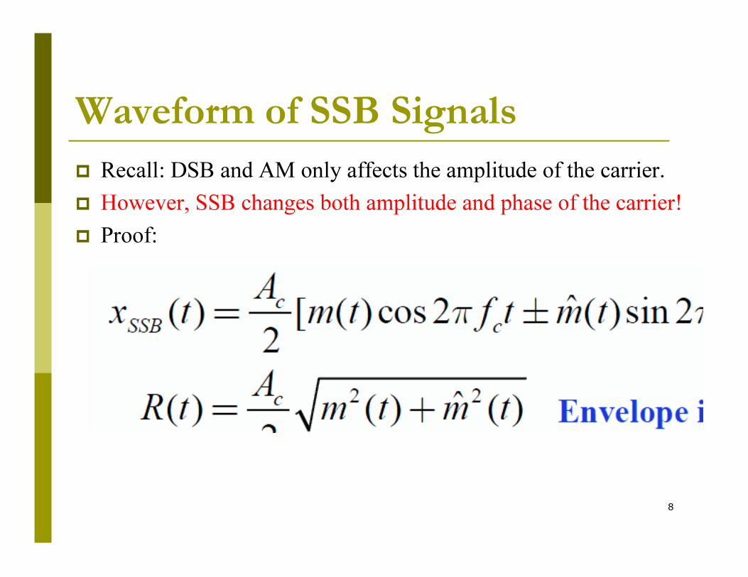
( ) ( )[ ]tftmtftmA
tscc
c
usbππ 2sin)(ˆ2cos)(
2)( −=
( )tftmAtSccdsbπ2cos)()( =
[ ])()(2
)(ccffMffM
AfS c
++−=
� Recall the definitions of pre-envelopes or analytic signals Mp(f) and Mn(f):
� The DSB signal is:
� Its FT is:
1
4
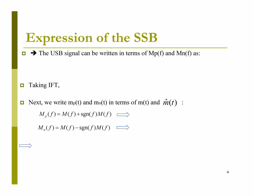
Expression of the SSB� � The USB signal can be written in terms of Mp(f) and Mn(f) as:
� Taking IFT,
� Next, we write mp(t) and mn(t) in terms of m(t) and :)(ˆ tm
)()sgn()()( fMffMfMp
+=
)()sgn()()( fMffMfMn
−=
5
Expression of the SSB
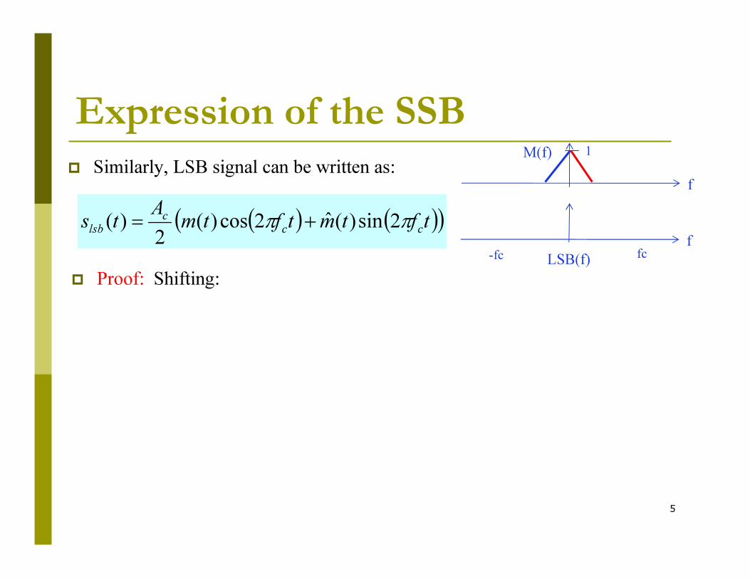
� Similarly, LSB signal can be written as:f
M(f)
f
LSB(f) fc-fc
( ) ( )( )tftmtftmA
tscc
c
lsbππ 2sin)(ˆ2cos)(
2)( +=
� Proof: Shifting:
1
6
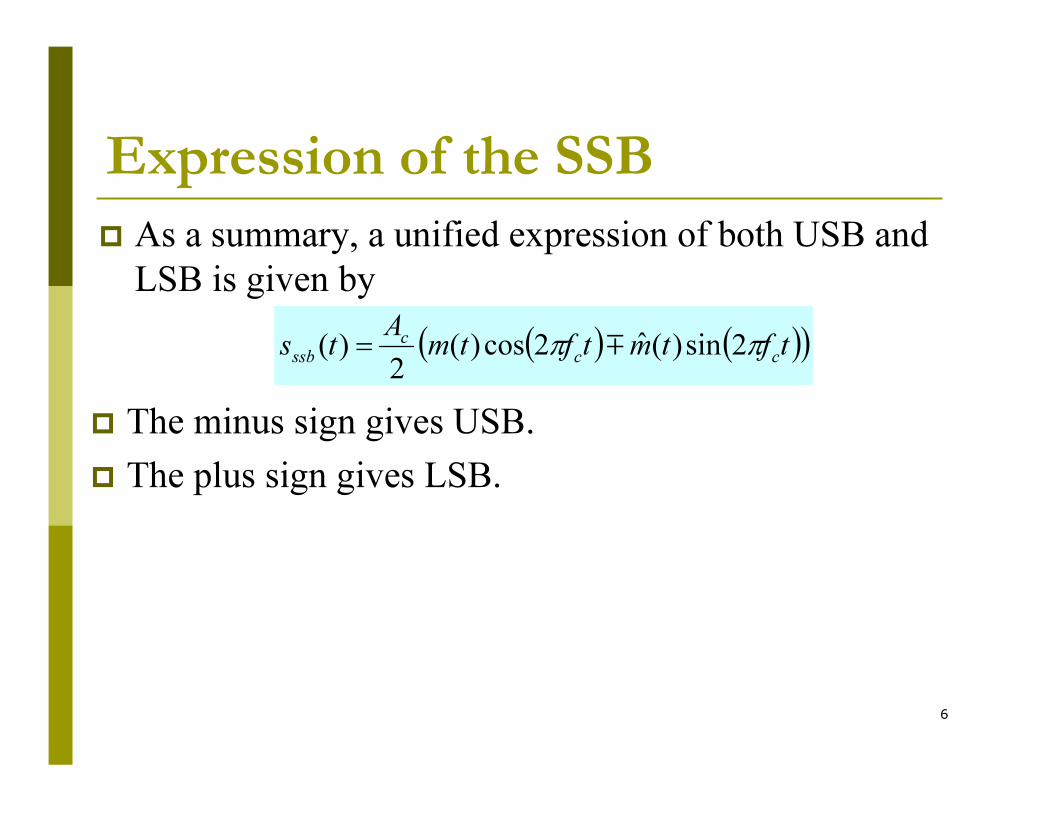
Expression of the SSB
� As a summary, a unified expression of both USB and
LSB is given by
( ) ( )( )tftmtftmA
tscc
c
ssbππ 2sin)(ˆ2cos)(
2)( m=
� The minus sign gives USB.
� The plus sign gives LSB.
7
Outline
� Expression of SSB signals
� Waveform of SSB signals
� Modulators for SSB:
� Frequency discrimination
� Phase discrimination
� Coherent Detection of SSB
8
Waveform of SSB Signals
� Recall: DSB and AM only affects the amplitude of the carrier.
� However, SSB changes both amplitude and phase of the carrier!
� Proof:
9
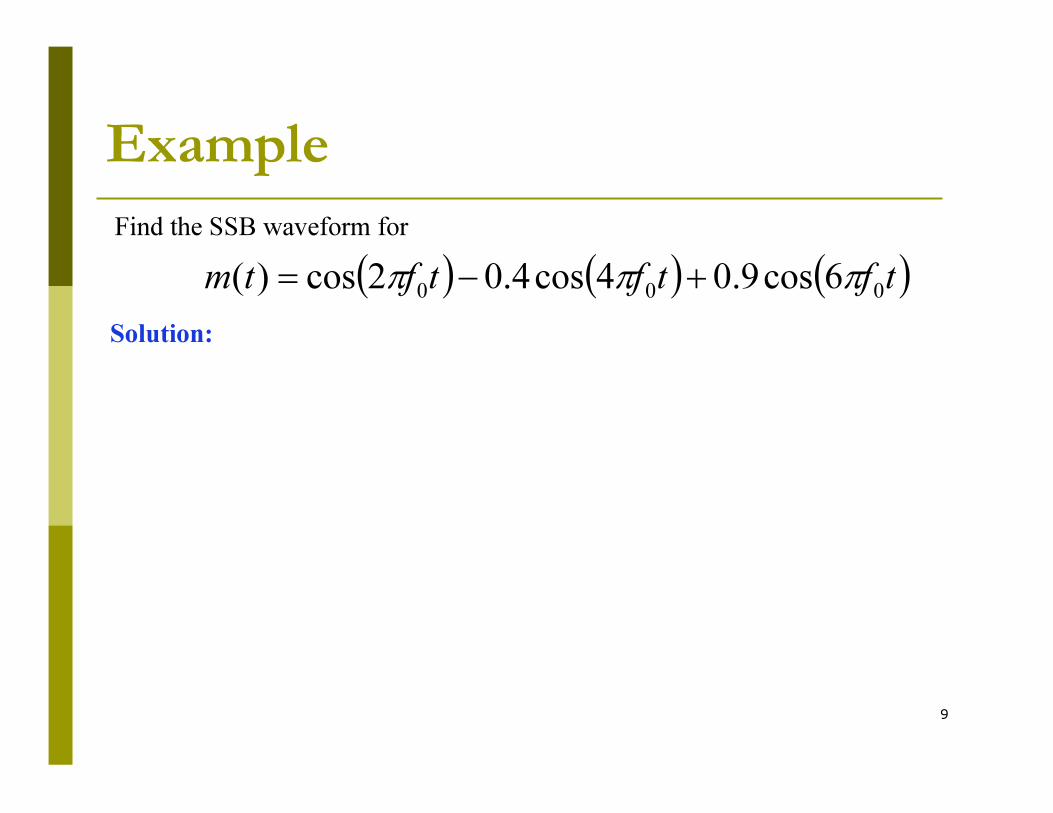
Example
( ) ( ) ( )tftftftm000
6cos9.04cos4.02cos)( πππ +−=
Find the SSB waveform for
Solution:
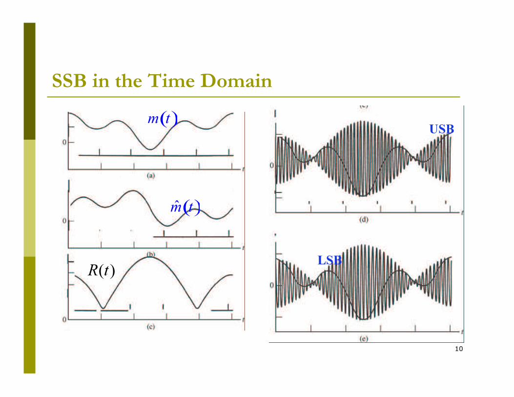
10
SSB in the Time Domain
( )m t
( )m̂ t
USB
LSB)(tR
11
Outline
� Expression of SSB signals
� Waveform of SSB signals
� Modulators for SSB:
� Method 1: frequency domain approach:
�Frequency discrimination
� Method 2: time domain approach:
� Phase discrimination
� Coherent Detection of SSB

12
Generation of SSB by
Frequency Discrimination
� Problems:
DSB
� Method 1: Generate DSB first, then filter out unnecessary sideband:
� Filter for USB: Filter for LSB:
f
M(f)
f
f
f
or
f f
13
Phase Discrimination
Modulation for SSB
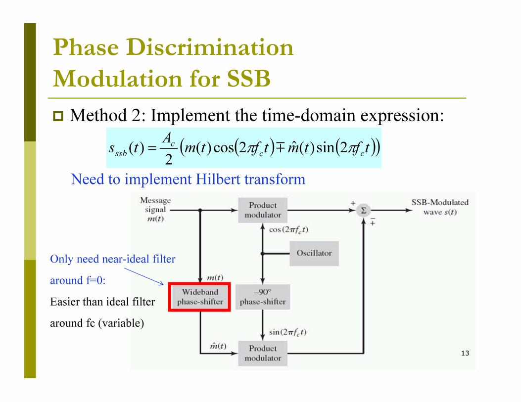
� Method 2: Implement the time-domain expression:
( ) ( )( )tftmtftmA
tscc
c
ssbππ 2sin)(ˆ2cos)(
2)( m=
Only need near-ideal filter
around f=0:
Easier than ideal filter
around fc (variable)
Need to implement Hilbert transform
14
Outline
� Expression of SSB signals
� Waveform of SSB signals
� Modulators for SSB:
� Frequency discrimination
� Phase discrimination
� Coherent Detection of SSB

15
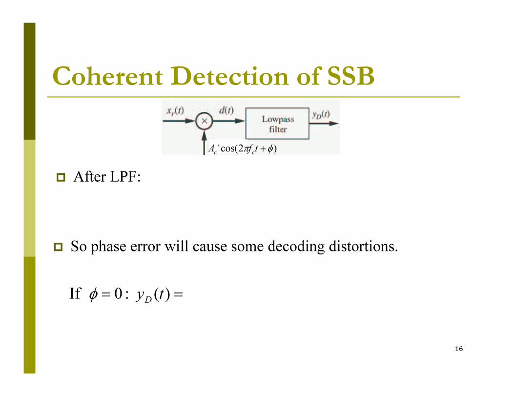
Coherent Detection of SSB
� SSB is similar to QAM that we studied before:
� � The coherent detection is still applicable to SSB:
� multiply with carrier, then LPF
� Assume demodulation carrier has a phase error:
)2cos(' φπ +tfAcc
)2sin()()2cos()()( 21
tftmAtftmAtsccccππ +=
16
Coherent Detection of SSB
)2cos(' φπ +tfAcc
� After LPF:
== )( :0 If tyD
φ
� So phase error will cause some decoding distortions.

16-1
Envelope Detection of SSB
Carrier reinsertion
is local carrier
From pilot tone or oscillator
ˆ( ) cos [ ( )cos( ) ( )sin( )]2
ˆ( ) cos ( )sin( )2 2
cc c c
c cc c
Ae t K t m t t m t t
A AK m t t m t t
If K large enough, e(t) ( ) cos .2
cc
AK m t t
This method is not efficient
which is a standard AM signal can use an envelope detector
DEnvelope y (t) ( ).2
cAK m t
cos cK t
17
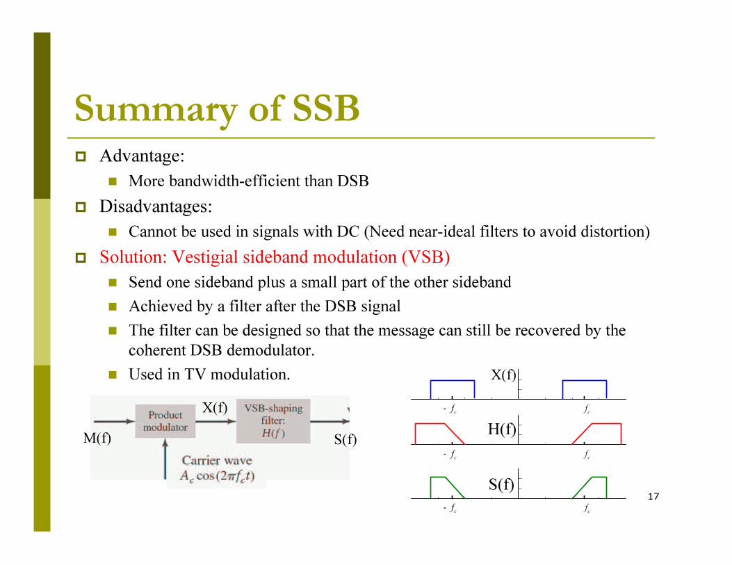
Summary of SSB� Advantage:
� More bandwidth-efficient than DSB
� Disadvantages:
� Cannot be used in signals with DC (Need near-ideal filters to avoid distortion)
� Solution: Vestigial sideband modulation (VSB)
� Send one sideband plus a small part of the other sideband
� Achieved by a filter after the DSB signal
� The filter can be designed so that the message can still be recovered by the
coherent DSB demodulator.
� Used in TV modulation.
X(f)
M(f) S(f)
cf
cf-
cf
cf-
cf
cf-
H(f)
S(f)
X(f)
18
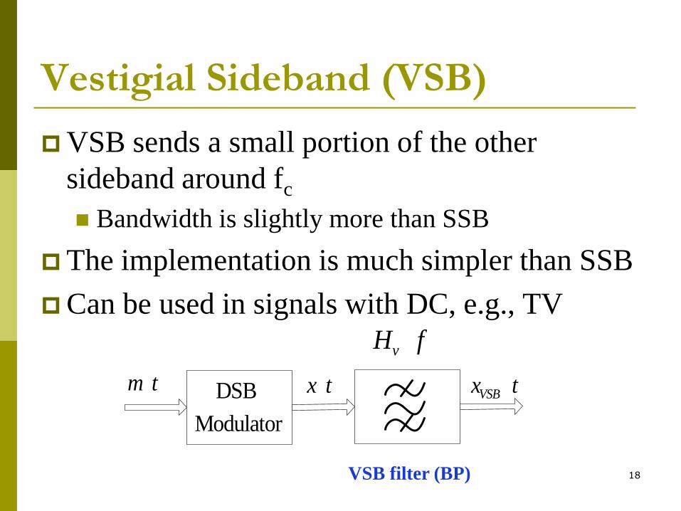
Vestigial Sideband (VSB)
VSB sends a small portion of the other
sideband around fc
Bandwidth is slightly more than SSB
The implementation is much simpler than SSB
Can be used in signals with DC, e.g., TV
x tm t DSB
Modulator
VSBx t
vH f
VSB filter (BP)

19
cont …
VSB modulation
x tm t DSB
Modulator
VSBx t
vH f
cfcf
X f
cfcf
vH f
cfcf
VSBX f
How to design VSB filter so that we can recover m(t)?
12
( ) [ ( ) ( )] ( )VSB c c vX f M f f M f f H f
VSB filter
DSB
VSB output
20
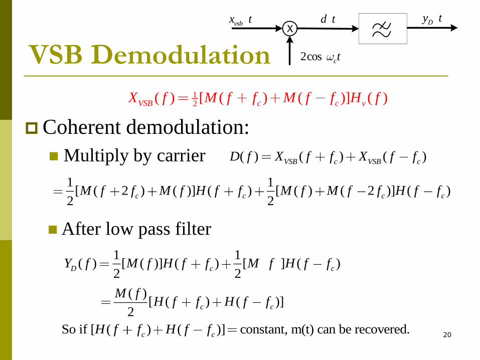
VSB Demodulation
Coherent demodulation:
Multiply by carrier
vsbx t d t
2cos ctw
Dy t
( ) ( ) ( )VSB c VSB cD f X f f X f f
12
( ) [ ( ) ( )] ( )VSB c c vX f M f f M f f H f
1 1[ ( 2 ) ( )] ( ) [ ( ) ( 2 )] ( )
2 2c c c cM f f M f H f f M f M f f H f f
1 1( ) [ ( )] ( ) [ ] ( )
2 2D c cY f M f H f f M f H f f
( )[ ( ) ( )]
2c c
M fH f f H f f
After low pass filter
So if [ ( ) ( )] constant, m(t) can be recovered.c cH f f H f f
21
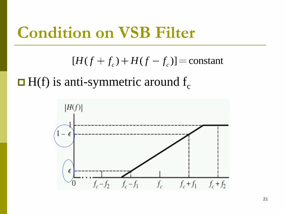
Condition on VSB Filter
H(f) is anti-symmetric around fc
[ ( ) ( )] constantc cH f f H f f
22
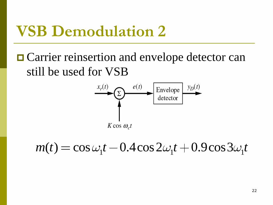
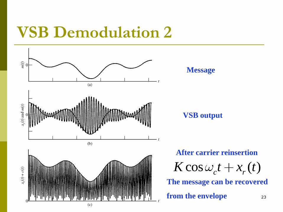
VSB Demodulation 2
Carrier reinsertion and envelope detector can
still be used for VSB
1 1 1( ) cos 0.4cos2 0.9cos3m t t t t
23
VSB Demodulation 2
Message
VSB output
After carrier reinsertion
cos ( )c rK t x tThe message can be recovered
from the envelope
24
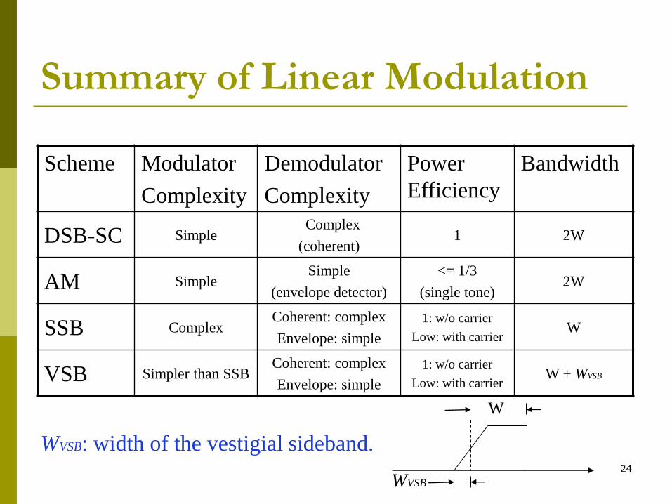
Summary of Linear Modulation
Scheme Modulator
Complexity
Demodulator
Complexity
Power
Efficiency
Bandwidth
DSB-SC Simple Complex
(coherent) 1 2W
AM Simple Simple
(envelope detector)
<= 1/3
(single tone) 2W
SSB Complex Coherent: complex
Envelope: simple
1: w/o carrier
Low: with carrier W
VSB Simpler than SSB Coherent: complex
Envelope: simple
1: w/o carrier
Low: with carrier W + WVSB
WVSB: width of the vestigial sideband.
WVSB
W