Embed Size (px)
Citation preview
Chapter 1: Introduction 1Comp 361, Spring 2005
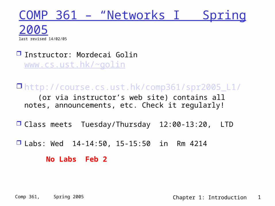
COMP 361 – “Networks I” Spring 2005last revised 14/02/05
Instructor: Mordecai Golin www.cs.ust.hk/~golin
http://course.cs.ust.hk/comp361/spr2005_L1/ (or via instructor’s web site) contains all notes,
announcements, etc. Check it regularly!
Class meets Tuesday/Thursday 12:00-13:20, LTD
Labs: Wed 14-14:50, 15-15:50 in Rm 4214 No Labs Feb 2
Chapter 1: Introduction 2Comp 361, Spring 2005
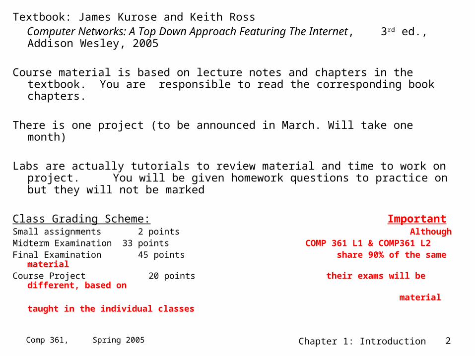
Textbook: James Kurose and Keith Ross Computer Networks: A Top Down Approach Featuring The Internet,
3rd ed., Addison Wesley, 2005
Course material is based on lecture notes and chapters in the textbook. You are responsible to read the corresponding book chapters.
There is one project (to be announced in March. Will take one month)
Labs are actually tutorials to review material and time to work on project. You will be given homework questions to practice on but they will not be marked
Class Grading Scheme: ImportantSmall assignments 2 points AlthoughMidterm Examination 33 points COMP 361 L1 & COMP361 L2 Final Examination 45 points share 90% of the same materialCourse Project 20 points their exams will be different, based on
material taught in the individual classes
Chapter 1: Introduction 3Comp 361, Spring 2005
Other Stuff
You must have a CS department UG UNIX account (not a windows account) in order to work on the project.
The project will have to be written in Java. Please see the notes section of the web site
http://course.cs.ust.hk/comp361/spr2005_L1/html/spr05sch.html under Lab notes (week 1) for a tutorial (re)introduction to Java.
The textbook has a an accompanying web site http://wps.aw.com/aw_kurose_network_3/
with useful resource material, e.g., illustrative applets.
Protected section of the site also has self-study quizzes.
Chapter 1: Introduction 4Comp 361, Spring 2005
Copyright Notice
Material that follows (in this section and all of the following) is substantially based on powerpoint slides developed and copyrighted by J.F. Kurose and K.W. Ross, 1996-2004.
Chapter 1: Introduction 5Comp 361, Spring 2005
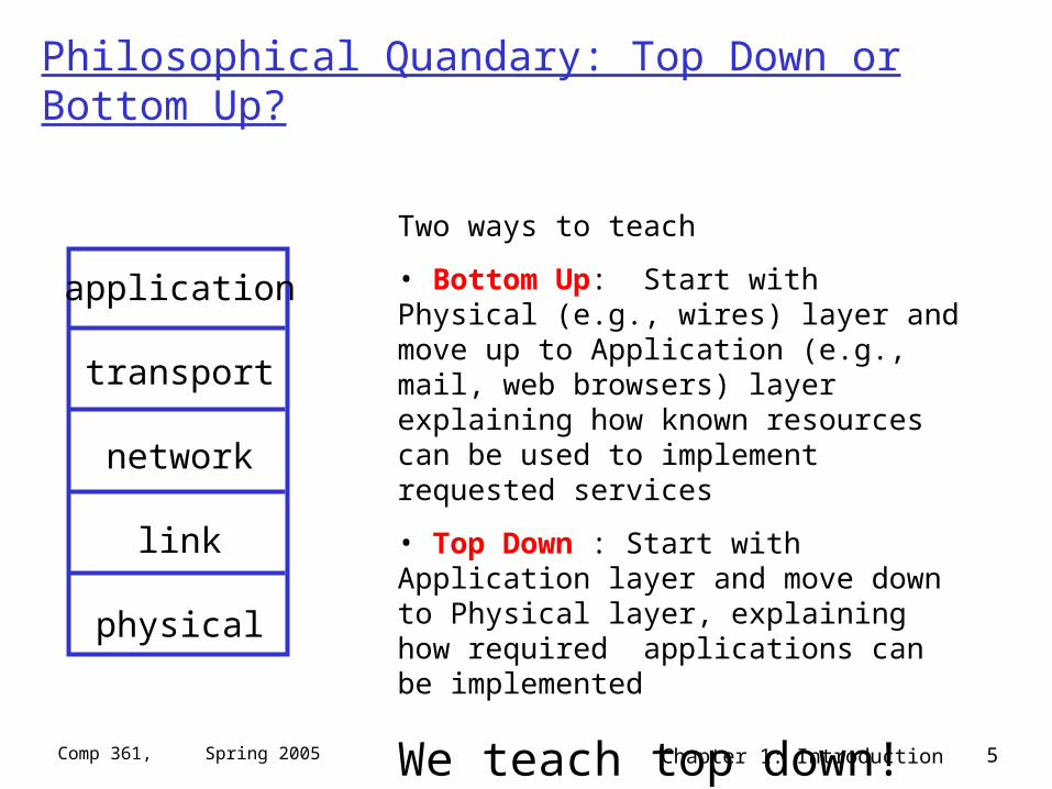
Philosophical Quandary: Top Down or Bottom Up?
application
transport
network
link
physical
Two ways to teach
• Bottom Up: Start with Physical (e.g., wires) layer and move up to Application (e.g., mail, web browsers) layer explaining how known resources can be used to implement requested services
• Top Down : Start with Application layer and move down to Physical layer, explaining how required applications can be implemented
We teach top down!
Chapter 1: Introduction 6Comp 361, Spring 2005
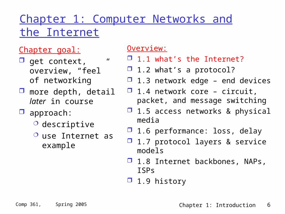
Chapter 1: Computer Networks and the Internet
Chapter goal: get context, overview,
“feel” of networking more depth, detail later
in course approach:
descriptive use Internet as
example
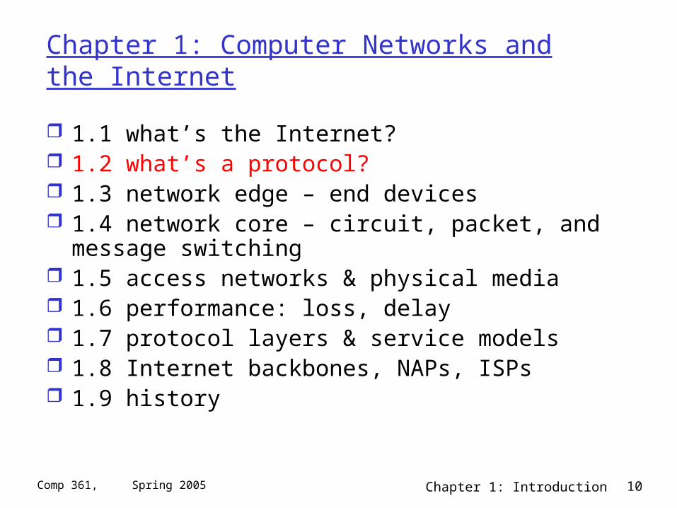
Overview: 1.1 what’s the Internet? 1.2 what’s a protocol? 1.3 network edge – end devices 1.4 network core – circuit, packet, and
message switching 1.5 access networks & physical media 1.6 performance: loss, delay 1.7 protocol layers & service models 1.8 Internet backbones, NAPs, ISPs 1.9 history
Chapter 1: Introduction 7Comp 361, Spring 2005
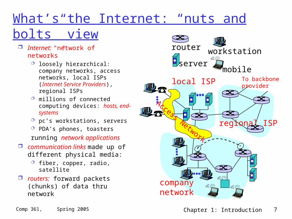
What’s the Internet: “nuts and bolts” view
Internet: “network of networks” loosely hierarchical: company
networks, access networks, local ISPs (Internet Service Providers), regional ISPs
millions of connected computing devices: hosts, end-systems
pc’s workstations, servers PDA’s phones, toasters
running network applications communication links made up
of different physical media: fiber, copper, radio, satellite
routers: forward packets (chunks) of data thru network
local ISP
companynetwork
regional ISP
router workstation
servermobile
Access Network
To backboneprovider
Chapter 1: Introduction 8Comp 361, Spring 2005
1.1 What’s the Internet: “nuts and bolts” view protocols control the sending and receiving of information
(messages) within the Internet e.g., TCP, IP, HTTP, FTP, PPP
Internet standards IETF, the Internet Engineering Task Force, is where many of the
“standards” used in the Internet today were discussed and created. IETF is a forum that is open to any interested individuals. The standards it created are contained in documents known as RFCs, or Request for comments.
Important websites:• Internet Engineering Task Force (IETF) – www.ietf.org• Internet Society – www.isoc.org• The World Wide Web Consortium (W3C) – www.w3.org/Consortium and others listed in section 1.1.3 of the text.
Chapter 1: Introduction 9Comp 361, Spring 2005
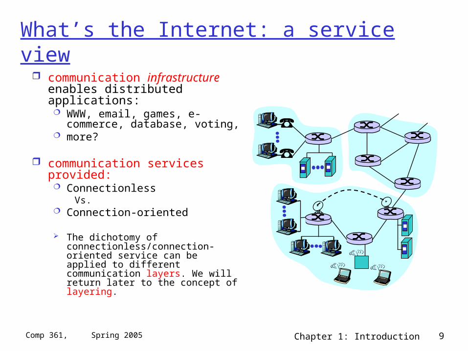
What’s the Internet: a service view
communication infrastructure enables distributed applications: WWW, email, games, e-
commerce, database, voting, more?
communication services provided: Connectionless
Vs. Connection-oriented
The dichotomy of connectionless/connection-oriented service can be applied to different communication layers. We will return later to the concept of layering.
Chapter 1: Introduction 10Comp 361, Spring 2005
Chapter 1: Computer Networks and the Internet
1.1 what’s the Internet? 1.2 what’s a protocol? 1.3 network edge – end devices 1.4 network core – circuit, packet, and message
switching 1.5 access networks & physical media 1.6 performance: loss, delay 1.7 protocol layers & service models 1.8 Internet backbones, NAPs, ISPs 1.9 history
Chapter 1: Introduction 11Comp 361, Spring 2005
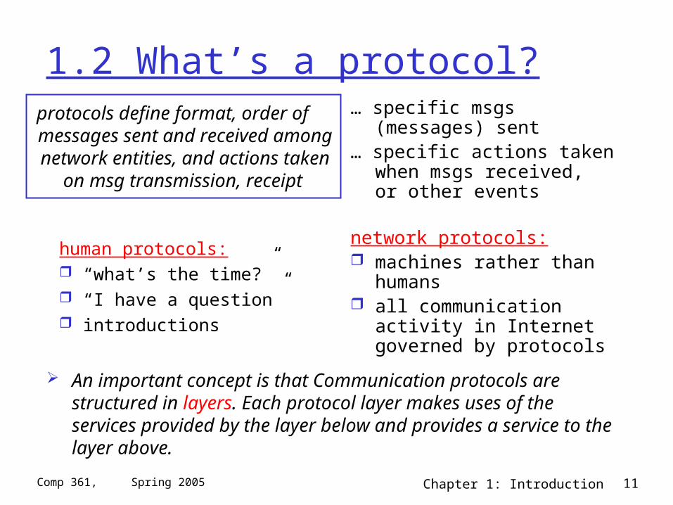
1.2 What’s a protocol?
human protocols: “what’s the time?” “I have a question” introductions
… specific msgs (messages) sent
… specific actions taken when msgs received, or other events
network protocols: machines rather than
humans all communication activity in
Internet governed by protocols
protocols define format, order of messages sent and received among network entities, and actions taken
on msg transmission, receipt
An important concept is that Communication protocols are structured in layers. Each protocol layer makes uses of the services provided by the layer below and provides a service to the layer above.
Chapter 1: Introduction 12Comp 361, Spring 2005
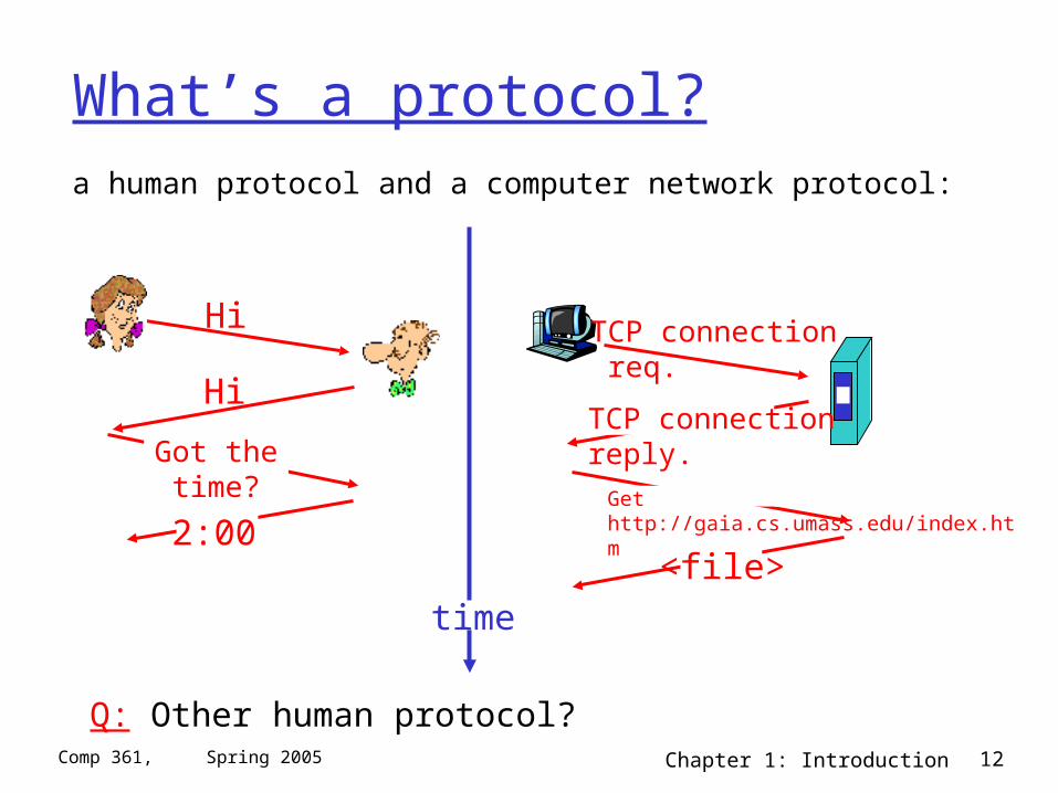
What’s a protocol?
a human protocol and a computer network protocol:
Q: Other human protocol?
Hi
Hi
Got thetime?
2:00
TCP connection req.
TCP connectionreply.Get http://gaia.cs.umass.edu/index.htm
<file>time
Chapter 1: Introduction 13Comp 361, Spring 2005
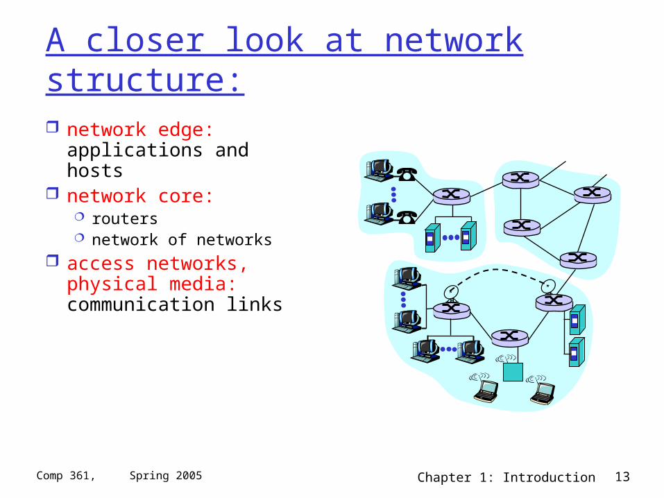
A closer look at network structure:
network edge: applications and hosts
network core: routers network of networks
access networks, physical media: communication links
Chapter 1: Introduction 14Comp 361, Spring 2005
Chapter 1: Computer Networks and the Internet
1.1 what’s the Internet? 1.2 what’s a protocol? 1.3 network edge – end devices 1.4 network core – circuit, packet, and message
switching 1.5 access networks & physical media 1.6 performance: loss, delay 1.7 protocol layers & service models 1.8 Internet backbones, NAPs, ISPs 1.9 history
Chapter 1: Introduction 15Comp 361, Spring 2005
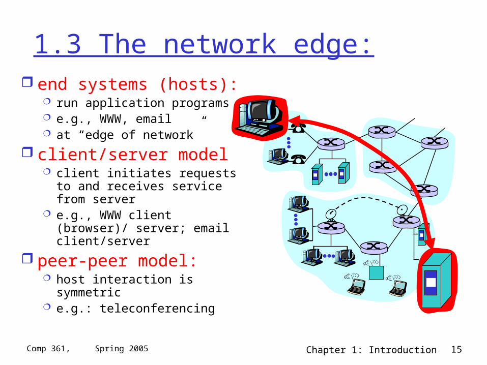
1.3 The network edge: end systems (hosts):
run application programs e.g., WWW, email at “edge of network”
client/server model client initiates requests to and
receives service from server e.g., WWW client (browser)/
server; email client/server
peer-peer model: host interaction is symmetric e.g.: teleconferencing
Chapter 1: Introduction 16Comp 361, Spring 2005
Network edge: connection-oriented service
Goal: data transfer between end sys.
handshaking: setup (prepare for) data transfer ahead of time Hello, hello back human
protocol set up “state” in two
communicating hosts TCP - Transmission
Control Protocol Internet’s connection-
oriented service
TCP service [RFC 793] reliable, in-order byte-
stream data transfer loss: acknowledgements
and retransmissions
flow control: sender won’t overwhelm
receiver
congestion control: senders “slow down sending
rate” when network congested
Chapter 1: Introduction 17Comp 361, Spring 2005
Network edge: connectionless service
Goal: data transfer between end systems same as before!
UDP - User Datagram Protocol [RFC 768]: Internet’s connectionless service unreliable data
transfer no flow control no congestion control but faster!
App’s using TCP: HTTP (WWW), FTP (file
transfer), Telnet (remote login), SMTP (email)
App’s using UDP: streaming media,
teleconferencing, Internet telephony
Why do we need both?
Chapter 1: Introduction 18Comp 361, Spring 2005
Chapter 1: Computer Networks and the Internet
1.1 what’s the Internet? 1.2 what’s a protocol? 1.3 network edge – end devices 1.4 network core – circuit, packet, and message
switching 1.5 access networks & physical media 1.6 performance: loss, delay 1.7 protocol layers & service models 1.8 Internet backbones, NAPs, ISPs 1.9 history
Chapter 1: Introduction 19Comp 361, Spring 2005
1.4 Network Core
Circuit Switching vs. Packet Switching
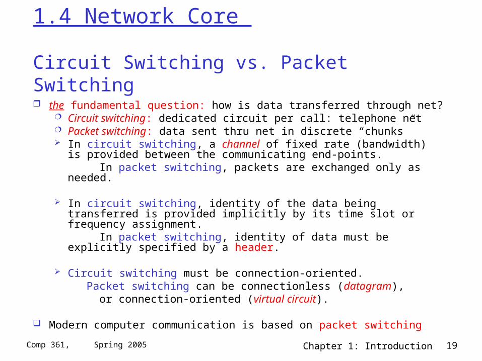
the fundamental question: how is data transferred through net? Circuit switching: dedicated circuit per call: telephone net Packet switching: data sent thru net in discrete “chunks” In circuit switching, a channel of fixed rate (bandwidth) is provided
between the communicating end-points. In packet switching, packets are exchanged only as needed.
In circuit switching, identity of the data being transferred is provided implicitly by its time slot or frequency assignment.
In packet switching, identity of data must be explicitly specified by a header.
Circuit switching must be connection-oriented. Packet switching can be connectionless (datagram), or connection-oriented (virtual circuit).
Modern computer communication is based on packet switching
Chapter 1: Introduction 20Comp 361, Spring 2005
Clarification
Switching Paradigm Circuit Switching vs Packet Switching (or Message
Switching) occurs at the physical switching layer. Circuit Switching is the system usually used by telephone networks but is not used in the Internet (except, e.g., when you dial up to an ISP using a modem).
Network Layer (Assuming Packet Switching) Datagram and Virtual Circuits are network service
models at the Network Layer. Current Internet architecture only provides a Datagram service.
Chapter 1: Introduction 21Comp 361, Spring 2005
Network Core - Circuit Switching
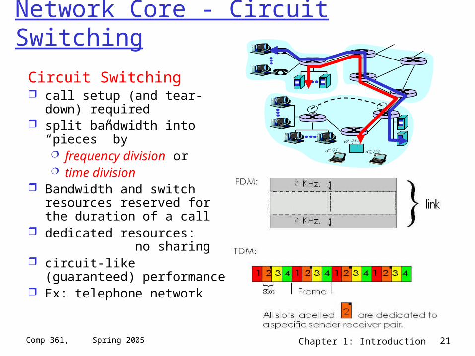
Circuit Switching call setup (and tear-down)
required split bandwidth into “pieces”
by frequency division or time division
Bandwidth and switch resources reserved for the duration of a call
dedicated resources: no sharing
circuit-like (guaranteed) performance
Ex: telephone network
Chapter 1: Introduction 22Comp 361, Spring 2005
Numerical example
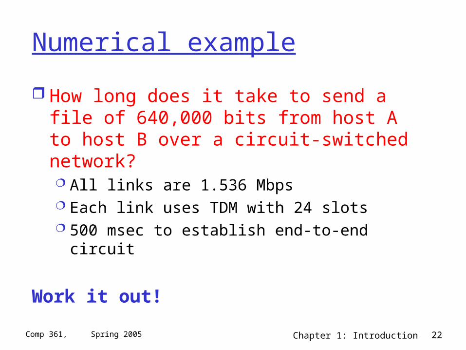
How long does it take to send a file of 640,000 bits from host A to host B over a circuit-switched network? All links are 1.536 Mbps Each link uses TDM with 24 slots 500 msec to establish end-to-end circuit
Work it out!
Chapter 1: Introduction 23Comp 361, Spring 2005
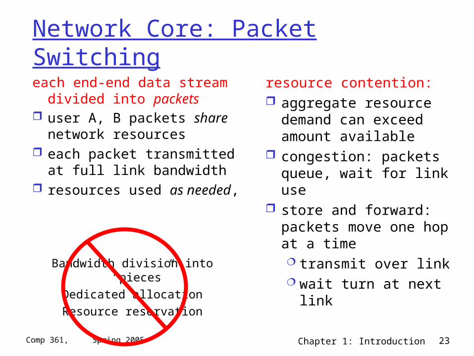
Network Core: Packet Switching
each end-end data stream divided into packets
user A, B packets share network resources
each packet transmitted at full link bandwidth
resources used as needed,
resource contention: aggregate resource
demand can exceed amount available
congestion: packets queue, wait for link use
store and forward: packets move one hop at a time transmit over link wait turn at next link
Bandwidth division into “pieces”
Dedicated allocation
Resource reservation
Chapter 1: Introduction 24Comp 361, Spring 2005
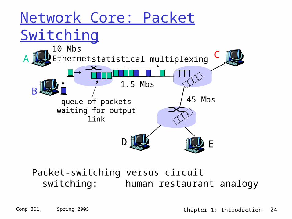
Network Core: Packet Switching
Packet-switching versus circuit switching: human restaurant analogy
A
B
C10 MbsEthernet
1.5 Mbs
45 Mbs
D E
statistical multiplexing
queue of packetswaiting for output
link
Chapter 1: Introduction 25Comp 361, Spring 2005
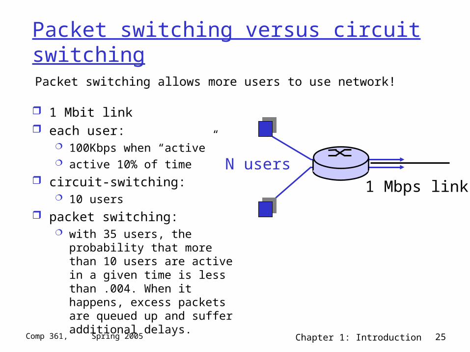
Packet switching versus circuit switching
1 Mbit link each user:
100Kbps when “active” active 10% of time
circuit-switching: 10 users
packet switching: with 35 users, the probability that
more than 10 users are active in a given time is less than .004. When it happens, excess packets are queued up and suffer additional delays.
Packet switching allows more users to use network!
N users1 Mbps link
Chapter 1: Introduction 26Comp 361, Spring 2005
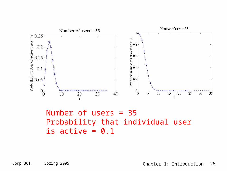
Number of users = 35Probability that individual user is active = 0.1
Chapter 1: Introduction 27Comp 361, Spring 2005
Packet switching versus circuit switching
Great for bursty data resource sharing no call setup
Excessive congestion: packet delay and loss protocols needed for reliable data transfer,
congestion control Q: How to provide circuit-like behavior?
bandwidth guarantees needed for audio/video apps
still an unsolved problem (chapter 6)
Is packet switching a “slam dunk winner?”
Chapter 1: Introduction 28Comp 361, Spring 2005
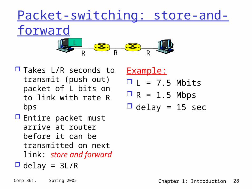
Packet-switching: store-and-forward
Takes L/R seconds to transmit (push out) packet of L bits on to link with rate R bps
Entire packet must arrive at router before it can be transmitted on next link: store and forward
delay = 3L/R
Example: L = 7.5 Mbits R = 1.5 Mbps delay = 15 sec
R R RL
Chapter 1: Introduction 29Comp 361, Spring 2005
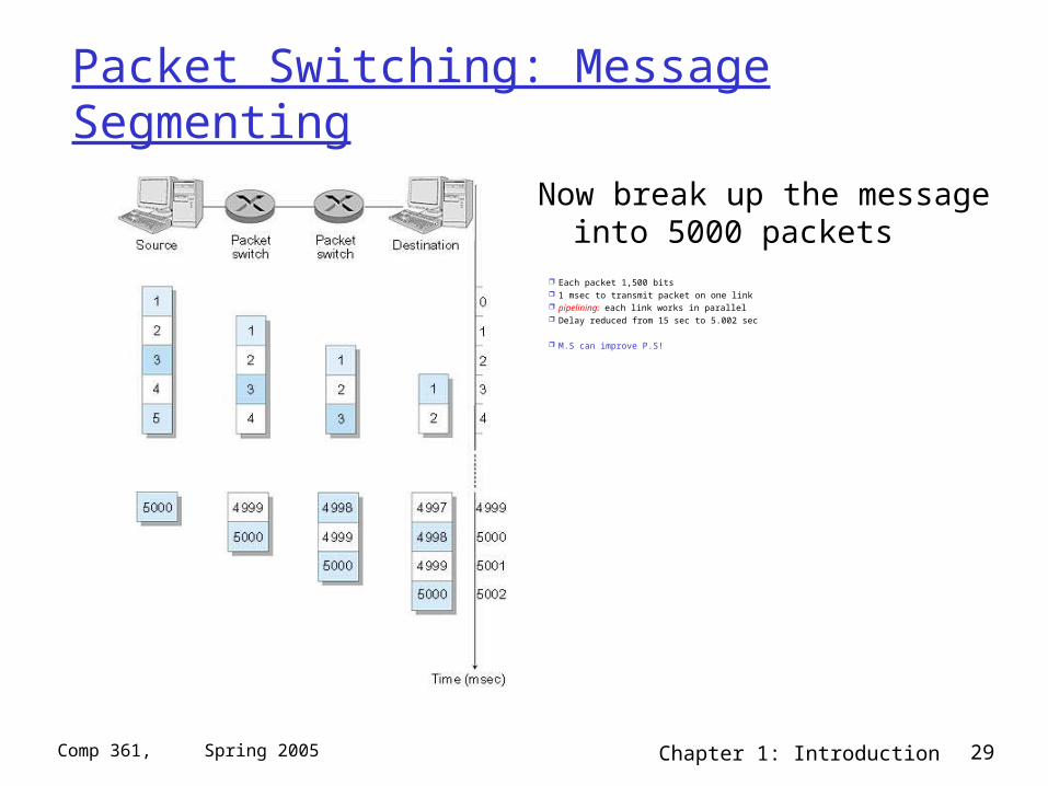
Packet Switching: Message Segmenting
Now break up the message into 5000 packets
Each packet 1,500 bits 1 msec to transmit packet on one link pipelining: each link works in parallel Delay reduced from 15 sec to 5.002 sec
M.S can improve P.S!
Chapter 1: Introduction 30Comp 361, Spring 2005
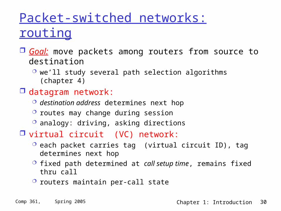
Packet-switched networks: routing
Goal: move packets among routers from source to destination we’ll study several path selection algorithms (chapter 4)
datagram network: destination address determines next hop routes may change during session analogy: driving, asking directions
virtual circuit (VC) network: each packet carries tag (virtual circuit ID), tag determines next
hop fixed path determined at call setup time, remains fixed thru call routers maintain per-call state
Chapter 1: Introduction 31Comp 361, Spring 2005
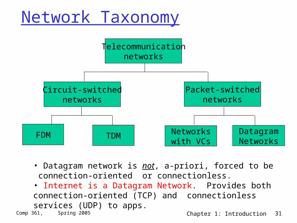
Network Taxonomy
Telecommunicationnetworks
Circuit-switchednetworks
FDM TDM
Packet-switchednetworks
Networkswith VCs
DatagramNetworks
• Datagram network is not, a-priori, forced to be connection-oriented or connectionless.• Internet is a Datagram Network. Provides both connection-oriented (TCP) and connectionless services (UDP) to apps.
Chapter 1: Introduction 32Comp 361, Spring 2005
Chapter 1: Computer Networks and the Internet
1.1 what’s the Internet? 1.2 what’s a protocol? 1.3 network edge – end devices 1.4 network core – circuit, packet, and message
switching 1.5 access networks & physical media 1.6 performance: loss, delay 1.7 protocol layers & service models 1.8 Internet backbones, NAPs, ISPs 1.9 history
Chapter 1: Introduction 33Comp 361, Spring 2005
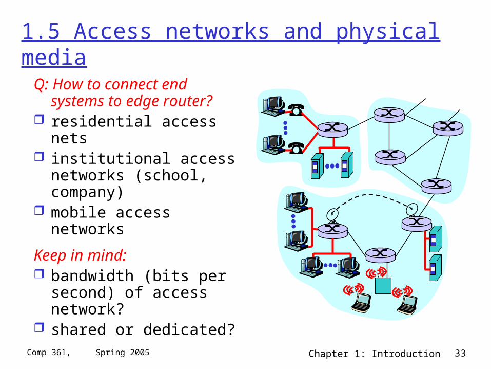
1.5 Access networks and physical media
Q: How to connect end systems to edge router?
residential access nets institutional access
networks (school, company)
mobile access networks
Keep in mind: bandwidth (bits per
second) of access network?
shared or dedicated?
Chapter 1: Introduction 34Comp 361, Spring 2005
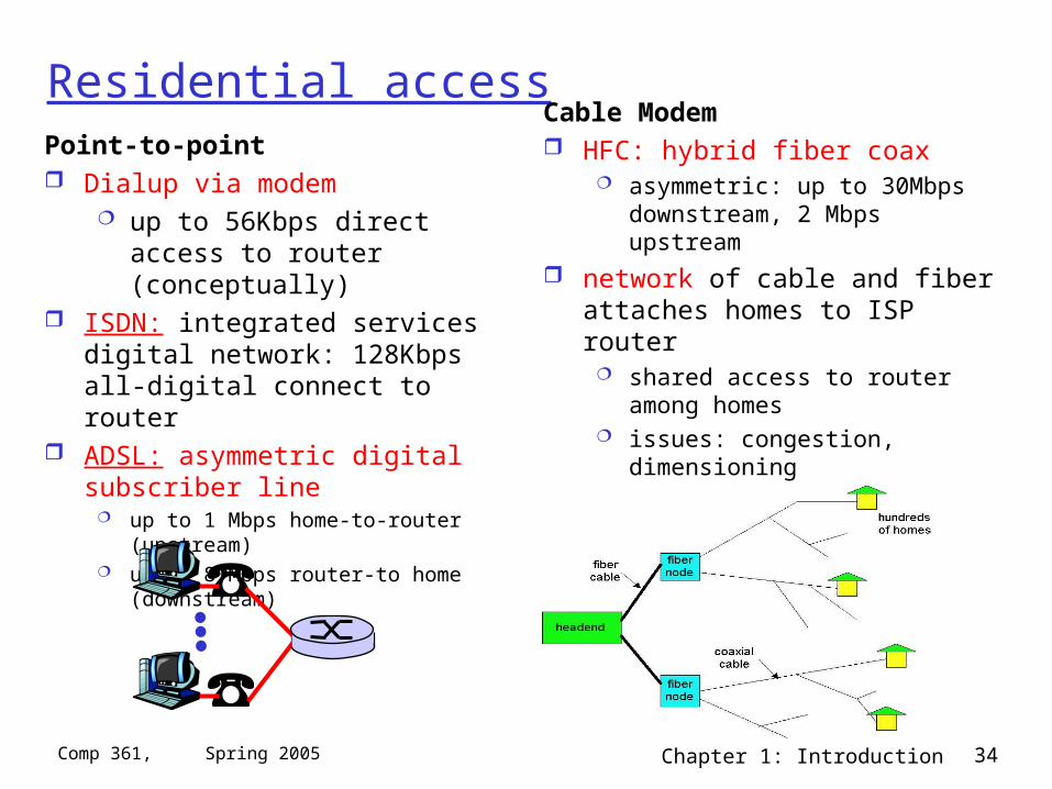
Residential accessPoint-to-point Dialup via modem
up to 56Kbps direct access to router (conceptually)
ISDN: integrated services digital network: 128Kbps all-digital connect to router
ADSL: asymmetric digital subscriber line
up to 1 Mbps home-to-router (upstream) up to 8 Mbps router-to home
(downstream)
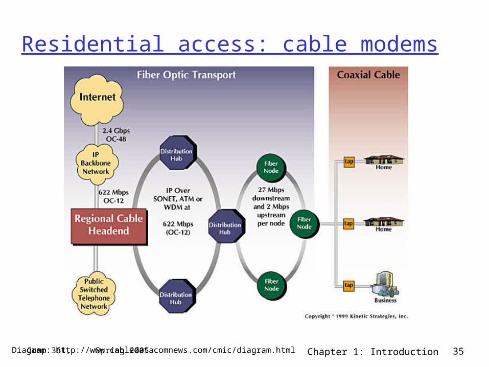
Cable Modem HFC: hybrid fiber coax
asymmetric: up to 30Mbps downstream, 2 Mbps upstream
network of cable and fiber attaches homes to ISP router
shared access to router among homes
issues: congestion, dimensioning deployment: available via cable TV
companies
Chapter 1: Introduction 35Comp 361, Spring 2005
Residential access: cable modems
Diagram: http://www.cabledatacomnews.com/cmic/diagram.html
Chapter 1: Introduction 36Comp 361, Spring 2005
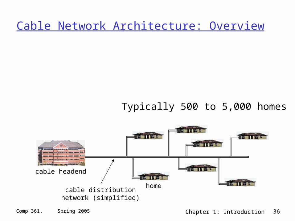
Cable Network Architecture: Overview
home
cable headend
cable distributionnetwork (simplified)
Typically 500 to 5,000 homes
Chapter 1: Introduction 37Comp 361, Spring 2005
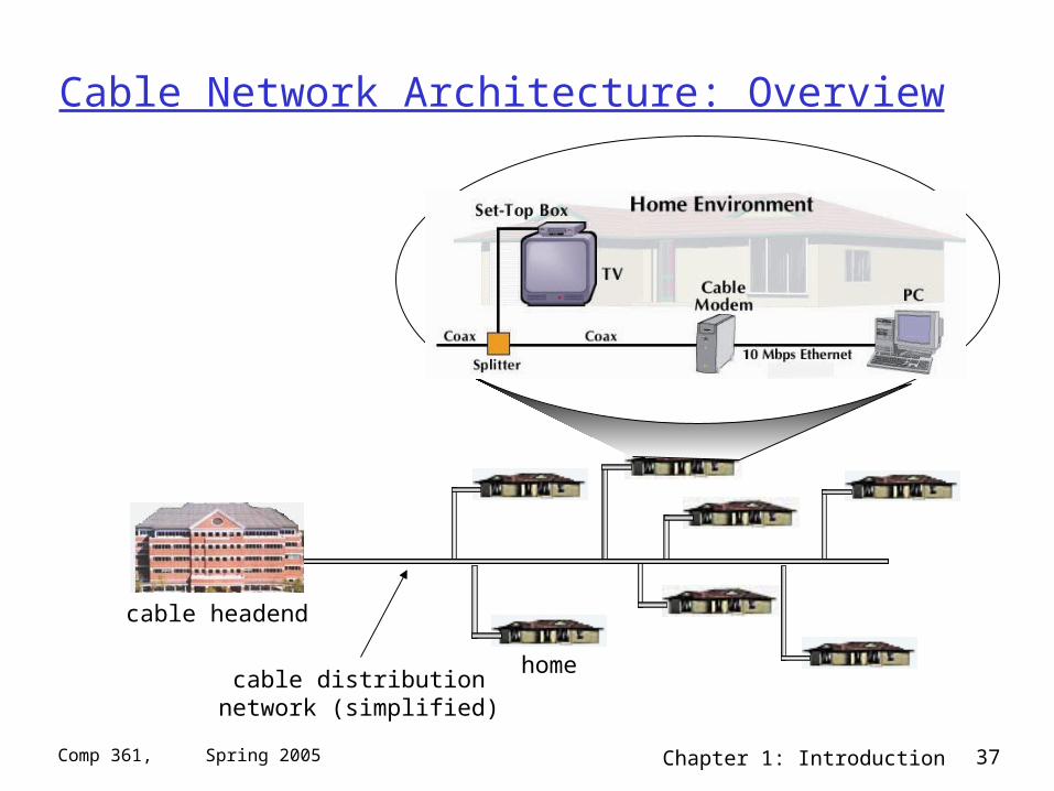
Cable Network Architecture: Overview
home
cable headend
cable distributionnetwork (simplified)
Chapter 1: Introduction 38Comp 361, Spring 2005
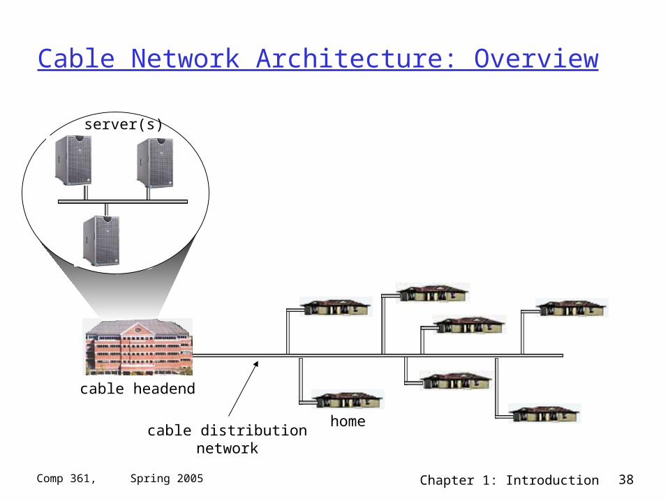
Cable Network Architecture: Overview
home
cable headend
cable distributionnetwork
server(s)
Chapter 1: Introduction 39Comp 361, Spring 2005
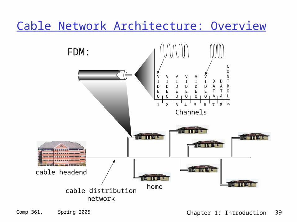
Cable Network Architecture: Overview
home
cable headend
cable distributionnetwork
Channels
VIDEO
VIDEO
VIDEO
VIDEO
VIDEO
VIDEO
DATA
DATA
CONTROL
1 2 3 4 5 6 7 8 9
FDM:
Chapter 1: Introduction 40Comp 361, Spring 2005
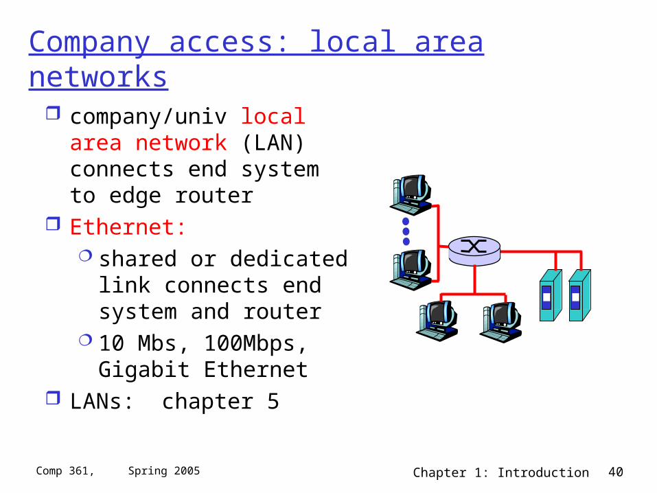
Company access: local area networks
company/univ local area network (LAN) connects end system to edge router
Ethernet: shared or dedicated link
connects end system and router
10 Mbs, 100Mbps, Gigabit Ethernet
LANs: chapter 5
Chapter 1: Introduction 41Comp 361, Spring 2005
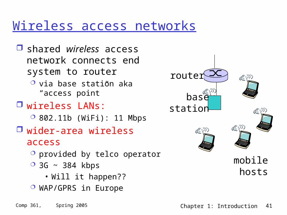
Wireless access networks
shared wireless access network connects end system to router via base station aka “access point”
wireless LANs: 802.11b (WiFi): 11 Mbps
wider-area wireless access provided by telco operator 3G ~ 384 kbps
• Will it happen?? WAP/GPRS in Europe
basestation
mobilehosts
router
Chapter 1: Introduction 42Comp 361, Spring 2005
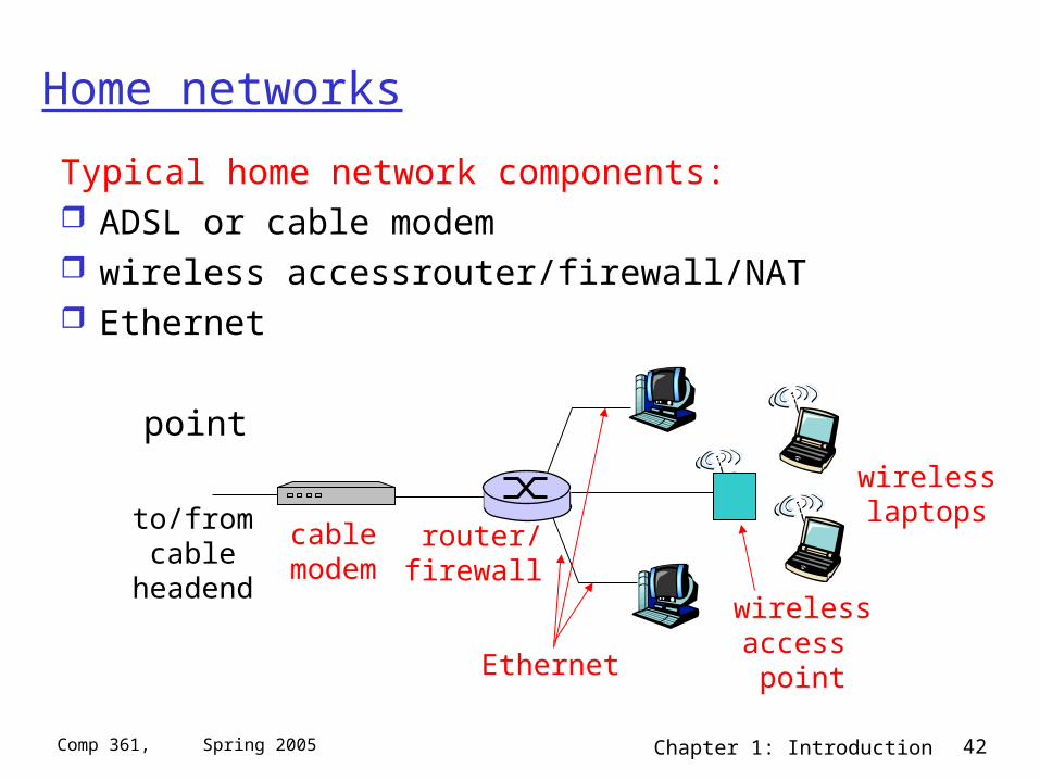
Home networks
Typical home network components: ADSL or cable modem wireless accessrouter/firewall/NAT Ethernet
point
wirelessaccess point
wirelesslaptops
router/firewall
cablemodem
to/fromcable
headend
Ethernet
Chapter 1: Introduction 43Comp 361, Spring 2005
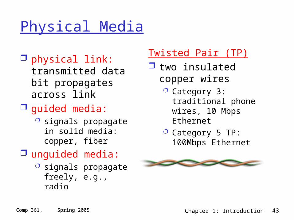
Physical Media
physical link: transmitted data bit propagates across link
guided media: signals propagate in solid
media: copper, fiber
unguided media: signals propagate freely,
e.g., radio
Twisted Pair (TP) two insulated copper
wires Category 3: traditional
phone wires, 10 Mbps Ethernet
Category 5 TP: 100Mbps Ethernet
Chapter 1: Introduction 44Comp 361, Spring 2005
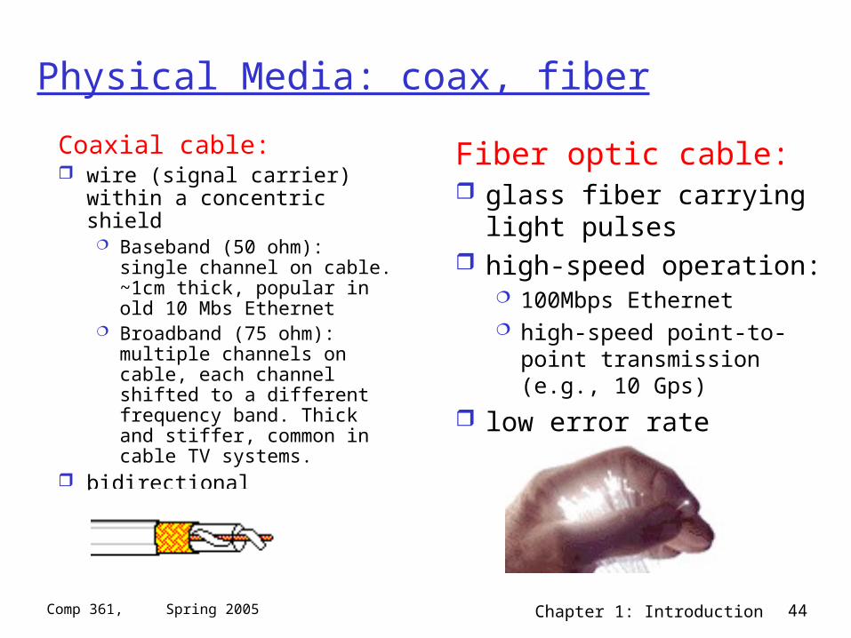
Physical Media: coax, fiber
Coaxial cable: wire (signal carrier) within a
concentric shield Baseband (50 ohm): single
channel on cable. ~1cm thick, popular in old 10 Mbs Ethernet
Broadband (75 ohm): multiple channels on cable, each channel shifted to a different frequency band. Thick and stiffer, common in cable TV systems.
bidirectional
Fiber optic cable: glass fiber carrying light
pulses high-speed operation:
100Mbps Ethernet high-speed point-to-point
transmission (e.g., 10 Gps)
low error rate
Chapter 1: Introduction 45Comp 361, Spring 2005
Physical media: radio
signal carried in electromagnetic spectrum
no physical “wire” bidirectional propagation environment
effects: reflection obstruction by objects interference
Radio link types: terrestrial microwave
e.g. up to 45 Mbps channels
LAN (e.g., Wifi) 2Mbps, 11Mbps
wide-area (e.g., cellular) e.g. 3G: hundreds of kbps
satellite up to 50Mbps channel (or multiple smaller
channels) 270 msec end-end delay geosynchronous versus low altitude
Chapter 1: Introduction 46Comp 361, Spring 2005
Chapter 1: Computer Networks and the Internet
1.1 what’s the Internet? 1.2 what’s a protocol? 1.3 network edge – end devices 1.4 network core – circuit, packet, and message
switching 1.5 access networks & physical media 1.6 performance: loss, delay 1.7 protocol layers & service models 1.8 Internet backbones, NAPs, ISPs 1.9 history
Chapter 1: Introduction 47Comp 361, Spring 2005
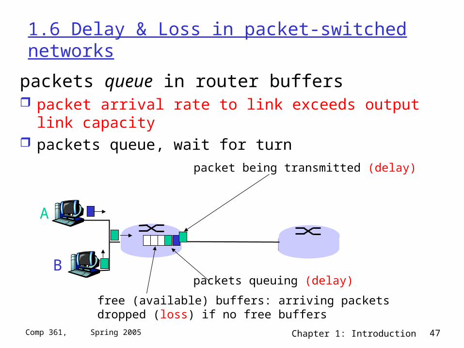
1.6 Delay & Loss in packet-switched networks
packets queue in router buffers packet arrival rate to link exceeds output link capacity packets queue, wait for turn
A
B
packet being transmitted (delay)
packets queuing (delay)
free (available) buffers: arriving packets dropped (loss) if no free buffers
Chapter 1: Introduction 48Comp 361, Spring 2005
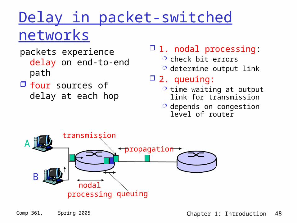
Delay in packet-switched networks
packets experience delay on end-to-end path
four sources of delay at each hop
1. nodal processing: check bit errors determine output link
2. queuing: time waiting at output link
for transmission depends on congestion
level of router
A
B
propagation
transmission
nodalprocessing queuing
Chapter 1: Introduction 49Comp 361, Spring 2005
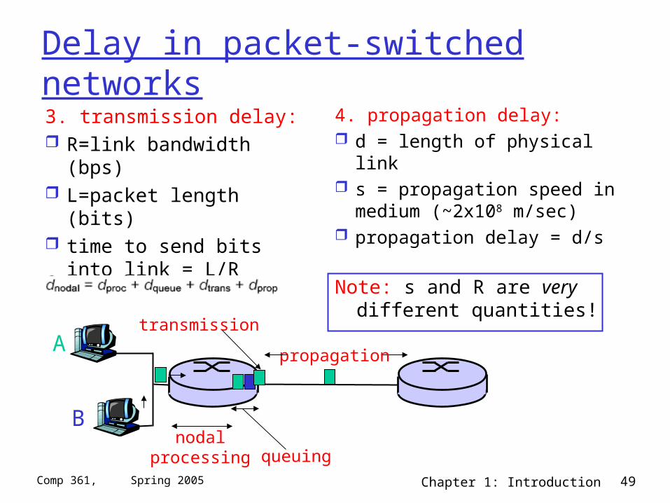
Delay in packet-switched networks
3. transmission delay: R=link bandwidth (bps) L=packet length (bits) time to send bits into
link = L/R
4. propagation delay: d = length of physical link s = propagation speed in
medium (~2x10⁸ m/sec) propagation delay = d/s
A
B
propagation
transmission
nodalprocessing queuing
Note: s and R are very different quantities!
Chapter 1: Introduction 50Comp 361, Spring 2005
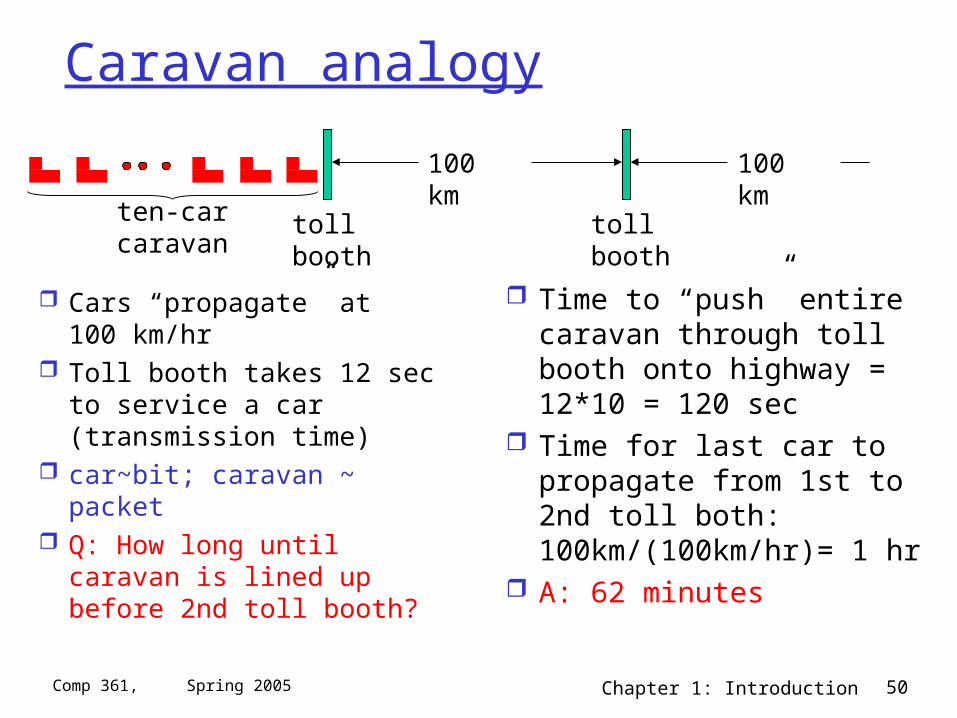
Caravan analogy
Cars “propagate” at 100 km/hr
Toll booth takes 12 sec to service a car (transmission time)
car~bit; caravan ~ packet Q: How long until caravan is
lined up before 2nd toll booth?
Time to “push” entire caravan through toll booth onto highway = 12*10 = 120 sec
Time for last car to propagate from 1st to 2nd toll both: 100km/(100km/hr)= 1 hr
A: 62 minutes
toll booth
toll booth
ten-car caravan
100 km
100 km
Chapter 1: Introduction 51Comp 361, Spring 2005
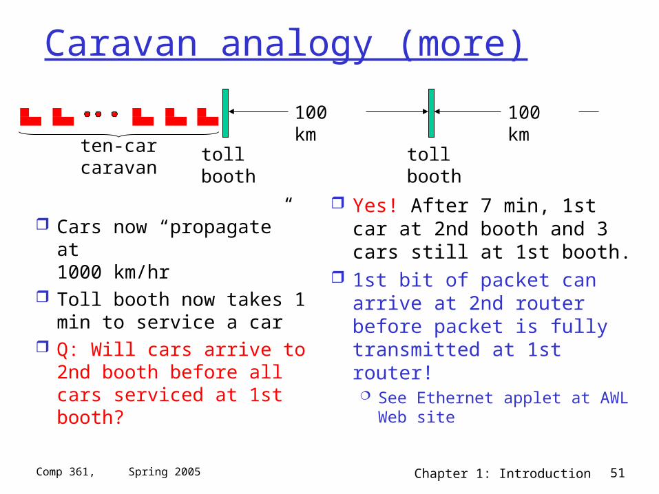
Caravan analogy (more)
Cars now “propagate” at 1000 km/hr
Toll booth now takes 1 min to service a car
Q: Will cars arrive to 2nd booth before all cars serviced at 1st booth?
Yes! After 7 min, 1st car at 2nd booth and 3 cars still at 1st booth.
1st bit of packet can arrive at 2nd router before packet is fully transmitted at 1st router! See Ethernet applet at AWL
Web site
toll booth
toll booth
ten-car caravan
100 km
100 km
Chapter 1: Introduction 52Comp 361, Spring 2005
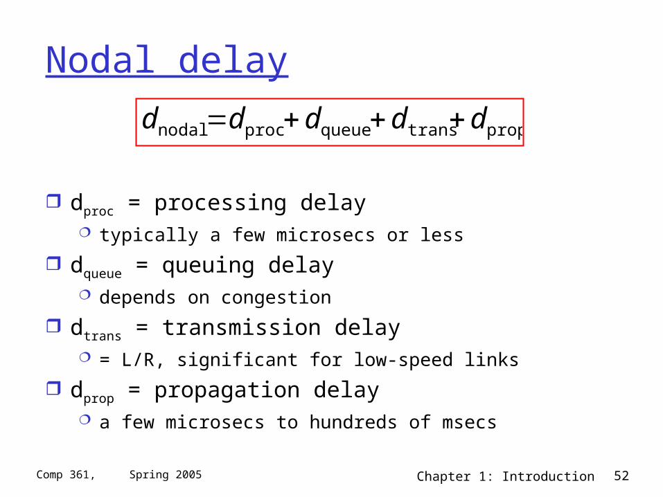
Nodal delay
dproc = processing delay typically a few microsecs or less
dqueue = queuing delay depends on congestion
dtrans = transmission delay = L/R, significant for low-speed links
dprop = propagation delay a few microsecs to hundreds of msecs
proptransqueueprocnodal ddddd
Chapter 1: Introduction 53Comp 361, Spring 2005
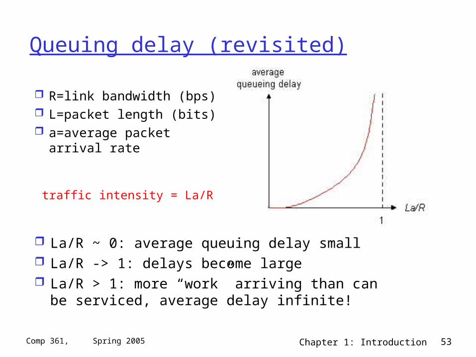
Queuing delay (revisited)
R=link bandwidth (bps) L=packet length (bits) a=average packet
arrival rate
traffic intensity = La/R
La/R ~ 0: average queuing delay small La/R -> 1: delays become large La/R > 1: more “work” arriving than can be
serviced, average delay infinite!
Chapter 1: Introduction 54Comp 361, Spring 2005
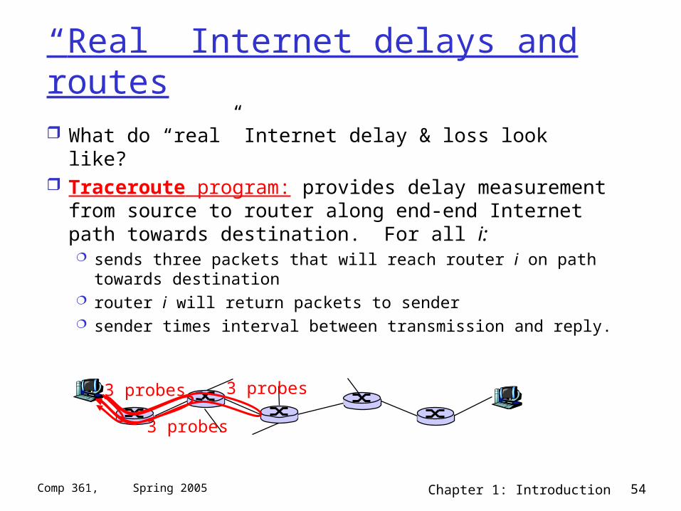
“Real” Internet delays and routes
What do “real” Internet delay & loss look like? Traceroute program: provides delay measurement
from source to router along end-end Internet path towards destination. For all i: sends three packets that will reach router i on path towards
destination router i will return packets to sender sender times interval between transmission and reply.
3 probes
3 probes
3 probes
Chapter 1: Introduction 55Comp 361, Spring 2005
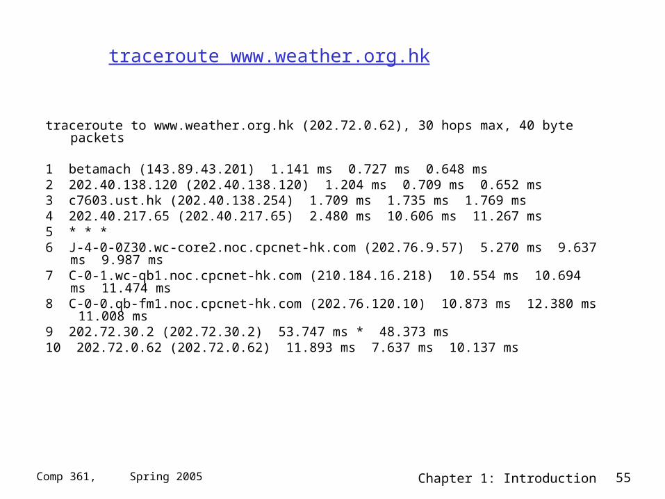
traceroute www.weather.org.hk
traceroute to www.weather.org.hk (202.72.0.62), 30 hops max, 40 byte packets
1 betamach (143.89.43.201) 1.141 ms 0.727 ms 0.648 ms2 202.40.138.120 (202.40.138.120) 1.204 ms 0.709 ms 0.652 ms3 c7603.ust.hk (202.40.138.254) 1.709 ms 1.735 ms 1.769 ms4 202.40.217.65 (202.40.217.65) 2.480 ms 10.606 ms 11.267 ms5 * * *6 J-4-0-0Z30.wc-core2.noc.cpcnet-hk.com (202.76.9.57) 5.270 ms 9.637 ms 9.987 ms7 C-0-1.wc-qb1.noc.cpcnet-hk.com (210.184.16.218) 10.554 ms 10.694 ms 11.474 ms8 C-0-0.qb-fm1.noc.cpcnet-hk.com (202.76.120.10) 10.873 ms 12.380 ms 11.008 ms9 202.72.30.2 (202.72.30.2) 53.747 ms * 48.373 ms10 202.72.0.62 (202.72.0.62) 11.893 ms 7.637 ms 10.137 ms
Chapter 1: Introduction 56Comp 361, Spring 2005
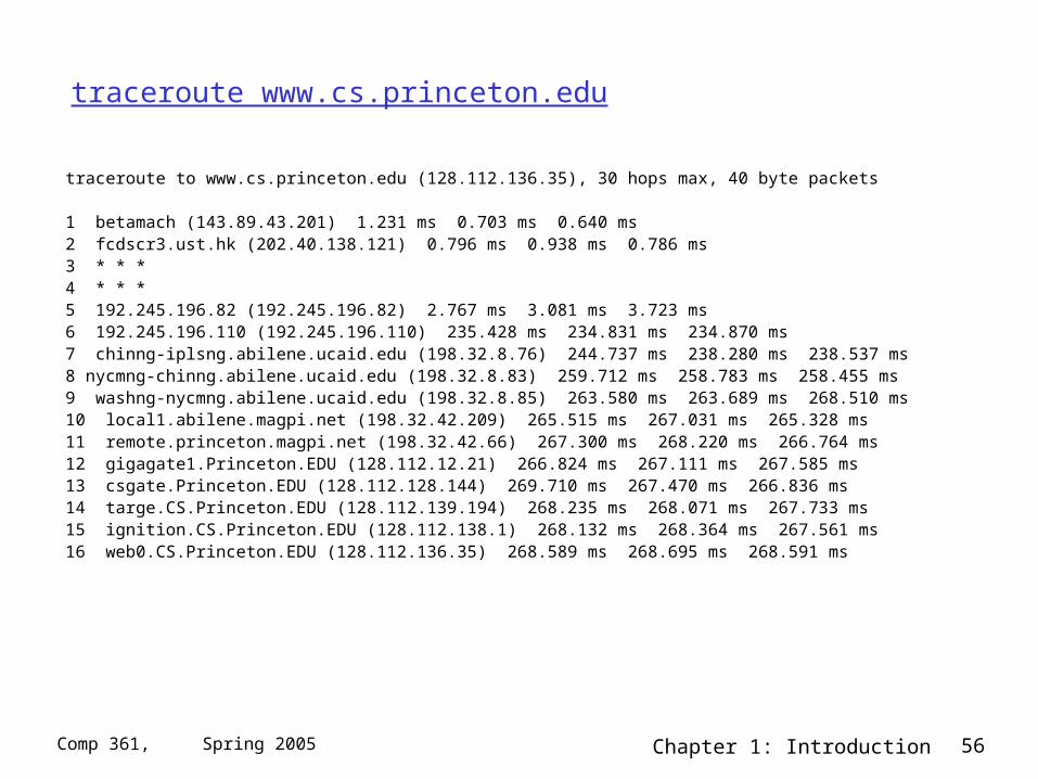
traceroute www.cs.princeton.edu
traceroute to www.cs.princeton.edu (128.112.136.35), 30 hops max, 40 byte packets
1 betamach (143.89.43.201) 1.231 ms 0.703 ms 0.640 ms2 fcdscr3.ust.hk (202.40.138.121) 0.796 ms 0.938 ms 0.786 ms3 * * *4 * * *5 192.245.196.82 (192.245.196.82) 2.767 ms 3.081 ms 3.723 ms6 192.245.196.110 (192.245.196.110) 235.428 ms 234.831 ms 234.870 ms7 chinng-iplsng.abilene.ucaid.edu (198.32.8.76) 244.737 ms 238.280 ms 238.537 ms8 nycmng-chinng.abilene.ucaid.edu (198.32.8.83) 259.712 ms 258.783 ms 258.455 ms9 washng-nycmng.abilene.ucaid.edu (198.32.8.85) 263.580 ms 263.689 ms 268.510 ms10 local1.abilene.magpi.net (198.32.42.209) 265.515 ms 267.031 ms 265.328 ms11 remote.princeton.magpi.net (198.32.42.66) 267.300 ms 268.220 ms 266.764 ms12 gigagate1.Princeton.EDU (128.112.12.21) 266.824 ms 267.111 ms 267.585 ms13 csgate.Princeton.EDU (128.112.128.144) 269.710 ms 267.470 ms 266.836 ms14 targe.CS.Princeton.EDU (128.112.139.194) 268.235 ms 268.071 ms 267.733 ms15 ignition.CS.Princeton.EDU (128.112.138.1) 268.132 ms 268.364 ms 267.561 ms16 web0.CS.Princeton.EDU (128.112.136.35) 268.589 ms 268.695 ms 268.591 ms
Chapter 1: Introduction 57Comp 361, Spring 2005
Packet loss
queue (aka buffer) preceding link in buffer has finite capacity
when packet arrives to full queue, packet is dropped (aka lost)
lost packet may be retransmitted by previous node, by source end system, or not retransmitted at all
Chapter 1: Introduction 58Comp 361, Spring 2005
Chapter 1: Computer Networks and the Internet
1.1 what’s the Internet? 1.2 what’s a protocol? 1.3 network edge – end devices 1.4 network core – circuit, packet, and message
switching 1.5 access networks & physical media 1.6 performance: loss, delay 1.7 protocol layers & service models 1.8 Internet backbones, NAPs, ISPs 1.9 history
Chapter 1: Introduction 59Comp 361, Spring 2005
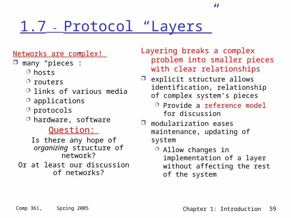
1.7 - Protocol “Layers”
Networks are complex! many “pieces”:
hosts routers links of various media applications protocols hardware, software
Question: Is there any hope of organizing
structure of network?Or at least our discussion of
networks?
Layering breaks a complex problem into smaller pieces with clear relationships
explicit structure allows identification, relationship of complex system’s pieces Provide a reference model for
discussion modularization eases maintenance,
updating of system Allow changes in implementation
of a layer without affecting the rest of the system
Chapter 1: Introduction 60Comp 361, Spring 2005
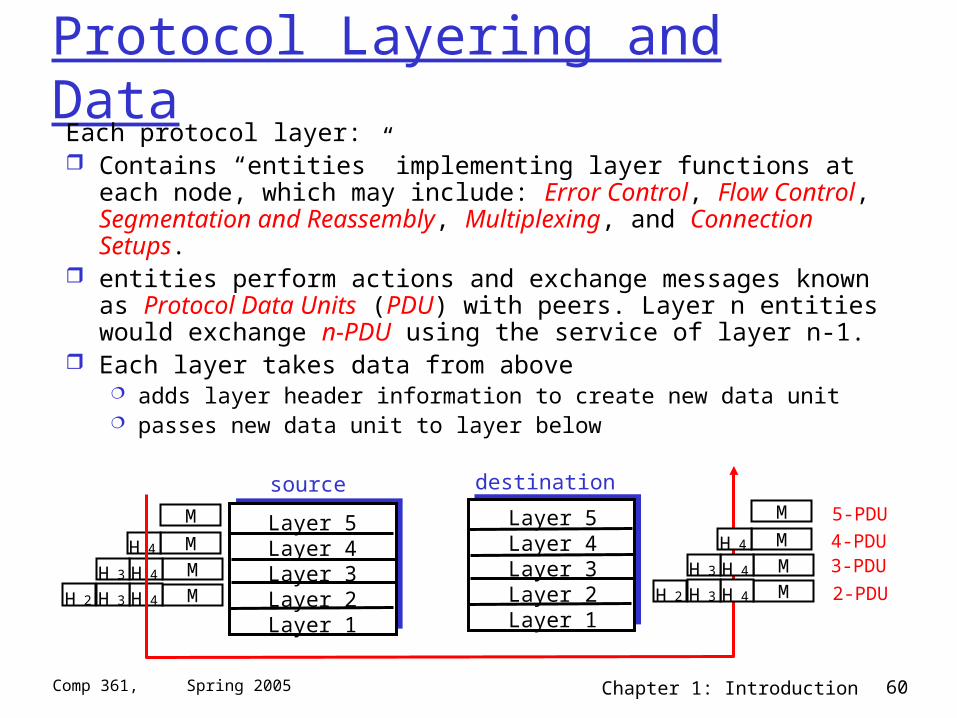
Protocol Layering and DataEach protocol layer: Contains “entities” implementing layer functions at each node,
which may include: Error Control, Flow Control, Segmentation and Reassembly, Multiplexing, and Connection Setups.
entities perform actions and exchange messages known as Protocol Data Units (PDU) with peers. Layer n entities would exchange n-PDU using the service of layer n-1.
Each layer takes data from above adds layer header information to create new data unit passes new data unit to layer below
M
MMM
H 4
H 4H 3
H 4H 3H 2
Layer 5Layer 4Layer 3Layer 2Layer 1
source destinationM
MMM
H 4
H 4H 3
H 4H 3H 2
5-PDU
4-PDU3-PDU
2-PDU
Layer 5Layer 4Layer 3Layer 2Layer 1
Chapter 1: Introduction 61Comp 361, Spring 2005
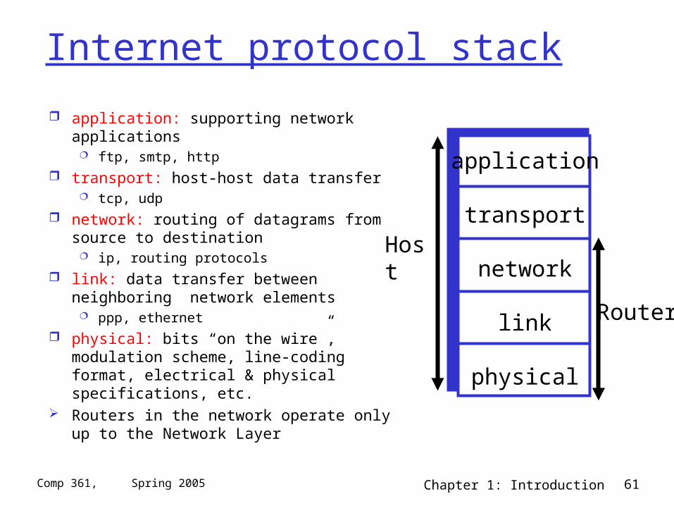
Internet protocol stack
application: supporting network applications ftp, smtp, http
transport: host-host data transfer tcp, udp
network: routing of datagrams from source to destination
ip, routing protocols link: data transfer between neighboring
network elements ppp, ethernet
physical: bits “on the wire”, modulation scheme, line-coding format, electrical & physical specifications, etc.
Routers in the network operate only up to the Network Layer
application
transport
network
link
physical
Host
Router
Chapter 1: Introduction 62Comp 361, Spring 2005
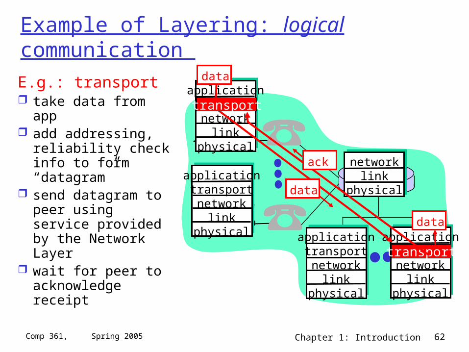
Example of Layering: logical communication
E.g.: transport take data from app add addressing,
reliability check info to form “datagram”
send datagram to peer using service provided by the Network Layer
wait for peer to acknowledge receipt
applicationtransportnetwork
linkphysical
applicationtransportnetwork
linkphysical application
transportnetwork
linkphysical
applicationtransportnetwork
linkphysical
networklink
physical
data
data
data
transport
transport
ack
Chapter 1: Introduction 63Comp 361, Spring 2005
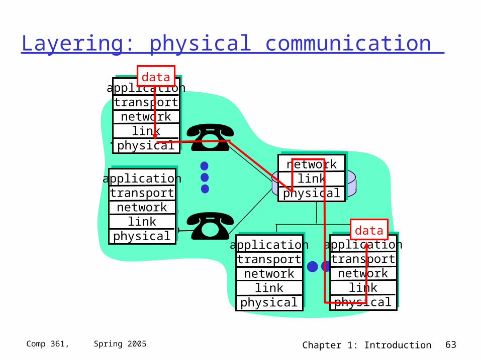
Layering: physical communication
applicationtransportnetwork
linkphysical
applicationtransportnetwork
linkphysical
applicationtransportnetwork
linkphysical
applicationtransportnetwork
linkphysical
networklink
physical
data
data
Chapter 1: Introduction 64Comp 361, Spring 2005
The OSI Reference Model
What we just saw is the Internet stack or, more formally, the TCP/IP Reference Model.
There is another breakdown of how to separate levels in open networks, the Open Systems Interconnection (OSI) Reference Model (1983 & then rev 1995)
In this course we usually use the TCP/IP RM.
Chapter 1: Introduction 65Comp 361, Spring 2005
Chapter 1: Computer Networks and the Internet
1.1 what’s the Internet? 1.2 what’s a protocol? 1.3 network edge – end devices 1.4 network core – circuit, packet, and message
switching 1.5 access networks & physical media 1.6 performance: loss, delay 1.7 protocol layers & service models 1.8 Internet backbones, NAPs, ISPs 1.9 history
Chapter 1: Introduction 66Comp 361, Spring 2005
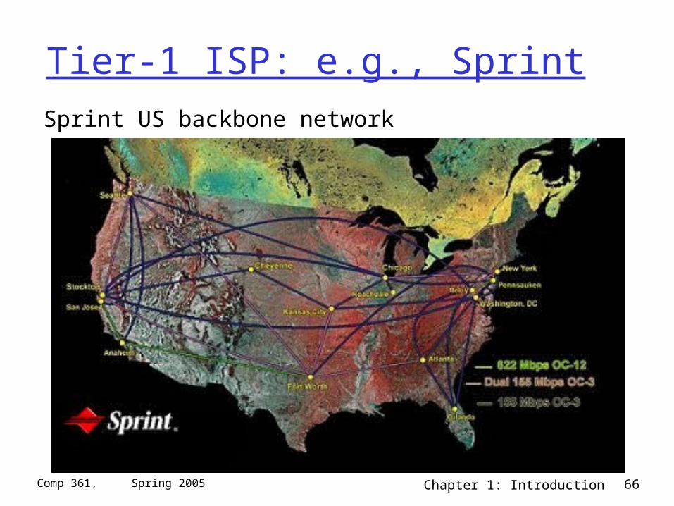
Tier-1 ISP: e.g., Sprint
Sprint US backbone network
Chapter 1: Introduction 67Comp 361, Spring 2005
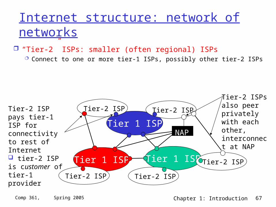
Internet structure: network of networks
“Tier-2” ISPs: smaller (often regional) ISPs Connect to one or more tier-1 ISPs, possibly other tier-2 ISPs
Tier 1 ISP
Tier 1 ISP
Tier 1 ISP
NAP
Tier-2 ISPTier-2 ISP
Tier-2 ISP Tier-2 ISP
Tier-2 ISP
Tier-2 ISP pays tier-1 ISP for connectivity to rest of Internet tier-2 ISP is customer oftier-1 provider
Tier-2 ISPs also peer privately with each other, interconnect at NAP
Chapter 1: Introduction 68Comp 361, Spring 2005
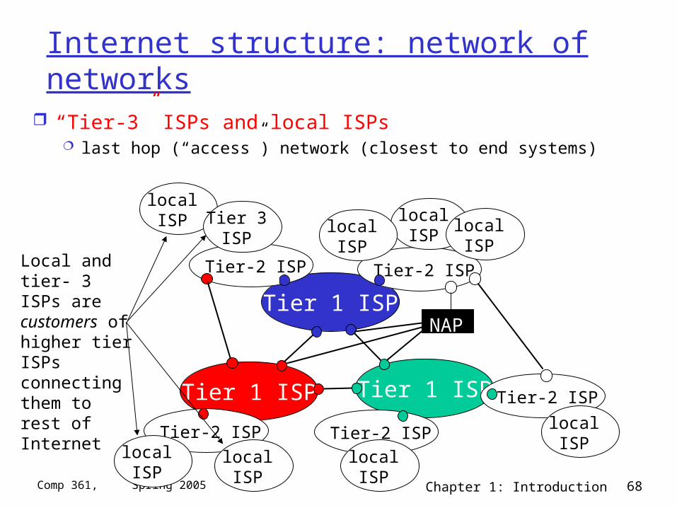
Internet structure: network of networks
“Tier-3” ISPs and local ISPs last hop (“access”) network (closest to end systems)
Tier 1 ISP
Tier 1 ISP
Tier 1 ISP
NAP
Tier-2 ISPTier-2 ISP
Tier-2 ISP Tier-2 ISP
Tier-2 ISP
localISPlocal
ISPlocalISP
localISP
localISP Tier 3
ISP
localISP
localISP
localISP
Local and tier- 3 ISPs are customers ofhigher tier ISPsconnecting them to rest of Internet
Chapter 1: Introduction 69Comp 361, Spring 2005
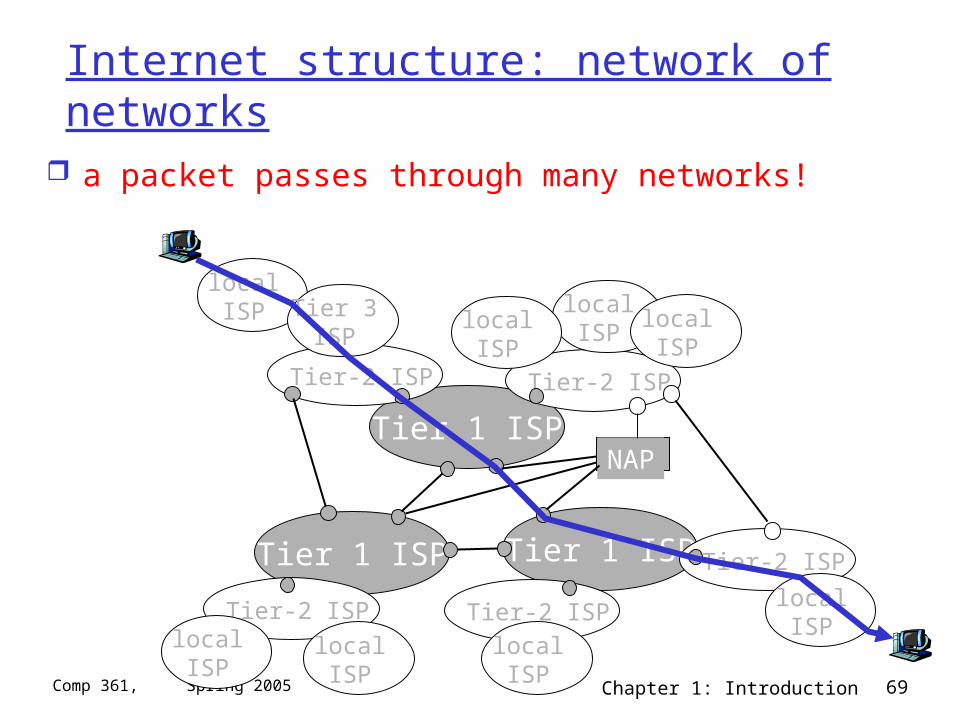
Internet structure: network of networks
a packet passes through many networks!
Tier 1 ISP
Tier 1 ISP
Tier 1 ISP
NAP
Tier-2 ISPTier-2 ISP
Tier-2 ISP Tier-2 ISP
Tier-2 ISP
localISPlocal
ISPlocalISP
localISP
localISP Tier 3
ISP
localISP
localISP
localISP
Chapter 1: Introduction 70Comp 361, Spring 2005
Chapter 1: Computer Networks and the Internet
1.1 what’s the Internet? 1.2 what’s a protocol? 1.3 network edge – end devices 1.4 network core – circuit, packet, and message
switching 1.5 access networks & physical media 1.6 performance: loss, delay 1.7 protocol layers & service models 1.8 Internet backbones, NAPs, ISPs 1.9 history
Chapter 1: Introduction 71Comp 361, Spring 2005
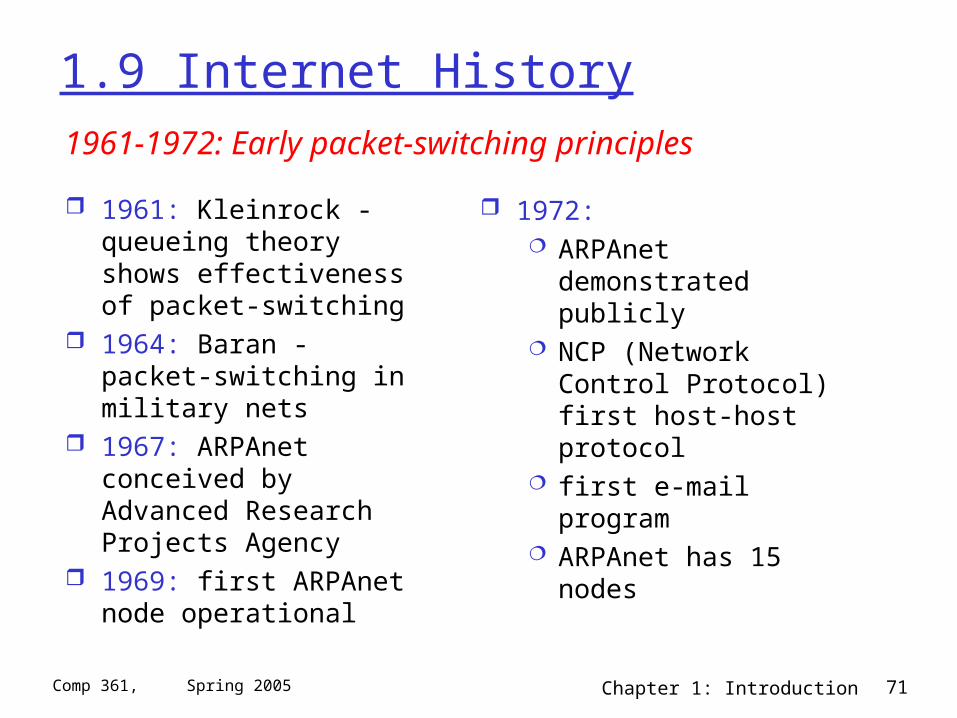
1.9 Internet History
1961: Kleinrock - queueing theory shows effectiveness of packet-switching
1964: Baran - packet-switching in military nets
1967: ARPAnet conceived by Advanced Research Projects Agency
1969: first ARPAnet node operational
1972: ARPAnet demonstrated
publicly NCP (Network Control
Protocol) first host-host protocol
first e-mail program ARPAnet has 15 nodes
1961-1972: Early packet-switching principles
Chapter 1: Introduction 72Comp 361, Spring 2005
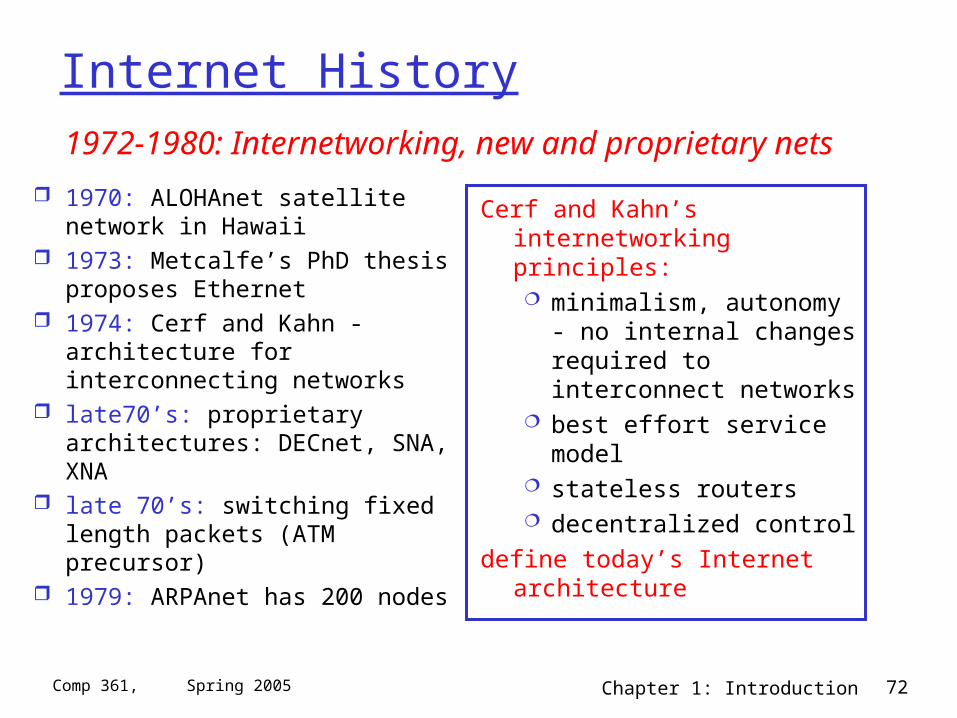
Internet History
1970: ALOHAnet satellite network in Hawaii
1973: Metcalfe’s PhD thesis proposes Ethernet
1974: Cerf and Kahn - architecture for interconnecting networks
late70’s: proprietary architectures: DECnet, SNA, XNA
late 70’s: switching fixed length packets (ATM precursor)
1979: ARPAnet has 200 nodes
Cerf and Kahn’s internetworking principles: minimalism, autonomy -
no internal changes required to interconnect networks
best effort service model stateless routers decentralized control
define today’s Internet architecture
1972-1980: Internetworking, new and proprietary nets
Chapter 1: Introduction 73Comp 361, Spring 2005
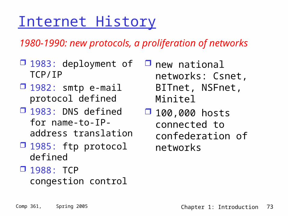
Internet History
1983: deployment of TCP/IP
1982: smtp e-mail protocol defined
1983: DNS defined for name-to-IP-address translation
1985: ftp protocol defined
1988: TCP congestion control
new national networks: Csnet, BITnet, NSFnet, Minitel
100,000 hosts connected to confederation of networks
1980-1990: new protocols, a proliferation of networks
Chapter 1: Introduction 74Comp 361, Spring 2005
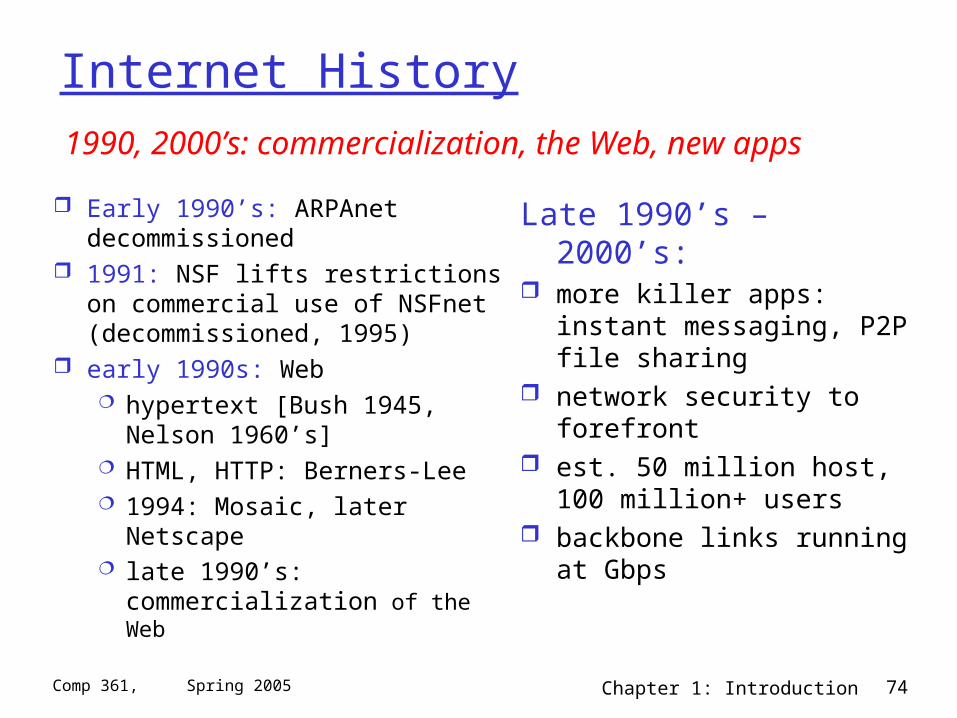
Internet History
Early 1990’s: ARPAnet decommissioned
1991: NSF lifts restrictions on commercial use of NSFnet (decommissioned, 1995)
early 1990s: Web hypertext [Bush 1945, Nelson
1960’s] HTML, HTTP: Berners-Lee 1994: Mosaic, later Netscape late 1990’s: commercialization
of the Web
Late 1990’s – 2000’s: more killer apps: instant
messaging, P2P file sharing network security to forefront est. 50 million host, 100
million+ users backbone links running at
Gbps
1990, 2000’s: commercialization, the Web, new apps
Chapter 1: Introduction 75Comp 361, Spring 2005
Chapter 1: Summary
Covered a “ton” of material!
Internet overview what’s a protocol? network edge, core,
access network performance: loss, delay layering and service
models backbones, NAPs, ISPs history
You now hopefully have: context, overview,
“feel” of networking more depth, detail later
in course