Embed Size (px)
Citation preview
Electranix Corporation, 12 – 75 Scurfield Blvd, Winnipeg, MB R3Y 1G4, Canada. www.electranix.com
Compact High Voltage Electric Power Transmission
By Dennis Woodford, P.Eng.
January 3, 2014
Introduction There is a developing need to provide high voltage electric power transmission that minimizes impact on the environment, agriculture and communities. Overhead transmission lines have been the normal located on designated rights-of-way. Acquiring new right-of way for overhead ac transmission lines is usually challenging to permit and in some jurisdiction impossible to obtain. To minimize the adverse effects of high voltage electric power transmission lines, new technologies are forthcoming that when applied may be more acceptable. By judicious compacting of high voltage direct current (HVDC) and high voltage alternating current (HVAC) transmission systems, existing rights-of-way can be utilized, such as along roads or rail lines. A concept for compacting transmission lines for this purpose is presented. Note: Portions or all of this paper may be copied, quoted or referred to so long as Electranix Corporation is acknowledged.

2
Compacting HVDC Transmission A new technology to convert HVAC power to HVDC power and vice versa is being successfully applied throughout the world enabling use of HVDC transmission. These converters apply large power transistors in what are designated voltage sourced converters (VSC) enabling VSC transmission. One popular configuration of voltage sourced converters is termed “symmetrical monopoles.” When a converter station has two symmetrical monopoles, it is not unlike the more conventional configuration of a “bipole” which also has two poles. When a bipole is rated at ±500 kV, it has two poles, each 500 kV and grounded at one end so that the generated HVDC line voltage has one polarity positive and the other polarity negative. A VSC symmetrical monopole which if rated at 500 kV, would operate at ±250 kV and does so with no firm ground connection that the conventional bipole requires. VSC transmission with two symmetrical monopoles would have two ±250 kV line circuits. VSC converters with a symmetrical monopole have been successfully applied in many VSC undersea or underground HVDC transmission systems. Electranix Corporation in 2007 assisted in writing a technical specification for the proposed Mid-Atlantic Power Pathway which required two 1000 MW VSC transmission lines each at ±320 kV and helped review the HVDC supplier’s bid. The VSC transmission circuit required undersea cable beneath the Chesapeake Bay, underground cable through wetlands and overhead line across the Delmarva Peninsula. This project was cancelled by PJM before a contract could be finalized. PJM is a regional transmission organization that coordinates the movement of wholesale electricity in 13 US states and the District of Columbia. The technology to build compact VSC overhead transmission is now available. One compacted configuration of VSC transmission based on two symmetrical monopoles is shown in Figure 1, where it is about the same height as a roadside 66 kV AC feeder. In this case the symmetrical monopoles are ±320 kV with a total power rating of over 2000 MW to 2400 MW. The advantages of this two symmetrical monopole VSC transmission system shown in Figure 1 are:
1. A very large capacity transmission line has a low profile and can be used on existing rights-of-way as indicated in Figure 1. If essential 66 kV AC feeders are required and tolerated to supply electricity to rural communities, farms and industrial operations, then such a compact VSC transmission line should receive similar consideration. The permitting process for such an overhead high power transmission line should therefore take much less time.

3
Figure 1: Compacted HVDC transmission with insulated cross arms compared with a
conventional 66 kV AC roadside feeder. Note the shield wires beneath the active conductors for the HVDC transmission
2. The operating voltage is much lower than conventional bipoles of similar power
rating. E.g. a conventional bipole of ±500 kV line voltage capable of transmitting 2400 MW on two energized conductor bundles (one positive and the other negative) is compared with VSC transmission with just two ±320 kV line voltage circuits capable of transmitting the same 2400 MW.
3. The choice of up to 320 kV overhead line voltages for the VSC transmission
system is to enable the circuit to go to the type of underground cables (or underwater where feasible) most commonly used with VSC converters. Such a conversion to cables would be useful when environmental, community build up
4
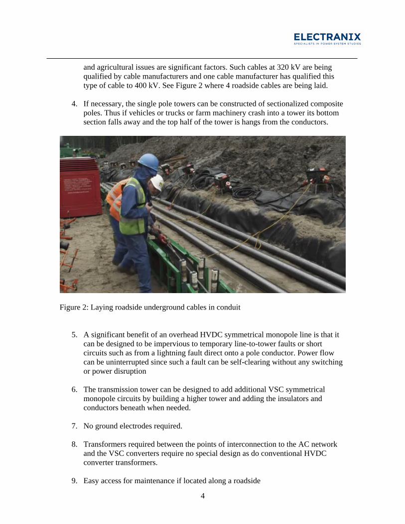
and agricultural issues are significant factors. Such cables at 320 kV are being qualified by cable manufacturers and one cable manufacturer has qualified this type of cable to 400 kV. See Figure 2 where 4 roadside cables are being laid.
4. If necessary, the single pole towers can be constructed of sectionalized composite poles. Thus if vehicles or trucks or farm machinery crash into a tower its bottom section falls away and the top half of the tower is hangs from the conductors.
Figure 2: Laying roadside underground cables in conduit
5. A significant benefit of an overhead HVDC symmetrical monopole line is that it can be designed to be impervious to temporary line-to-tower faults or short circuits such as from a lightning fault direct onto a pole conductor. Power flow can be uninterrupted since such a fault can be self-clearing without any switching or power disruption
6. The transmission tower can be designed to add additional VSC symmetrical monopole circuits by building a higher tower and adding the insulators and conductors beneath when needed.
7. No ground electrodes required.
8. Transformers required between the points of interconnection to the AC network and the VSC converters require no special design as do conventional HVDC converter transformers.
9. Easy access for maintenance if located along a roadside
5
The main disadvantages of this compact HVDC line are:
1. The tower looks top heavy.
2. Costs for compact HVDC transmission may not be lower than the conventional HVDC transmission lines perhaps because more towers are needed per mile (12 to 16 compact towers/mile compared to about 4 per mile for conventional HVDC towers). Losses must be taken into account when optimizing the 4 pole conductors and towers of the compact line possibly adding to cost.
3. Transmission line maintenance with one or both symmetrical monopoles energized may require special consideration.
Comparison of the HVDC Compact Line with Conventional Lines For comparison purposes, the ±500 kV 2000 plus MW tower designs considered by Manitoba Hydro in its Bipole III Environmental Impact Statement1 are used. A typical self-supporting structure is shown in Figure 3a, and an equivalent rated ±320 kV VSC transmission tower is shown in Figure 3b to the same scale. The conductors of the compact VSC transmission line could be conventional aluminum-conductor-steel reinforced of at least 4.475 cm diameter2 for single conductor bundles or at least 3.038 cm diameter3 if a two conductor bundle is on each pole. These pole conductors would be supported by insulated cross-arms as shown in Figures 1 and 3b. The two grounded shield wires beneath the energized conductors are required for safety and according to the IEEE National Electric Safety Code, must have a minimum ground clearance at maximum sag of 4.7 m if beside a road where trucks and farm machinery can pass beneath, and 7 m beside a rail line. These shield wires are grounded at each tower and are not energized. Preliminary studies of field and effects indicate this compact VSC transmission line can be designed on the concepts presented herein. The shield wires beneath the energized HVDC conductors shown in Figure 3(b) also serve to maintain the ground level potential gradient to an acceptable level so that a person walking beneath would experience minimum if any annoyance. This would not be a safety issue. An advantage of HVDC transmission over AC transmission is that the magnetic field generated by the current flowing in the conductors is constant like the earth’s naturally occurring magnetic field but with a slightly higher level of magnitude beneath the transmission line at high power loading. Alternating current on the other hand from an AC transmission line has been a greater issue of concern.
1 http://www.hydro.mb.ca/projects/bipoleIII/eis/download/chapter3__project_description.pdf - see Figure 3.4-2 2 Bluebird 3 Cardinal

6
Figure 3: Physical comparison of conventional HVDC bipole lattice tower with a
compact VSC transmission tower with similar power transmission capacity Insulated cross-arms can also be with a single insulator per conductor or conductor bundle as shown in Figure 4. This is designed by the Swedish Transmission Research Institute (STRI) for a compact 400 kV AC tower.
(a) Typical self-supporting suspension
tower configuration for ±500 kV HVDC, 2000 to 2500 MW
(b) Compact VSC transmission tower configuration for two ±320 kV symmetrical monopoles, 2000 MW to 2400 MW. 2 m sag.

7
Figure 4: Insulated cross-arms for a compact 400 kV AC transmission tower (Courtesy of
STRI)
Example - Manitoba Hydro’s Bipole III Much controversy has arisen over the Government of Manitoba insisting that Bipole III take an extensive route around the west side of Lake Winnipeg. The much shorter route on the east side of Lake Winnipeg was prevented by the Manitoba Government to preserve the pristine forest there. Application for this area to be a World Heritage Site failed but they will try again to maintain a case for retaining the west side route. However, this “pristine forest” has already been “devastated” by the winter roads as shown in Figure 5.

8
Figure 5: On a winter road in Manitoba (courtesy photo by trucker “bobthedog” on
http://www.trucknetuk.com/phpBB/viewtopic.php?f=2&t=37818&start=210 ) A route of a winter road where an east side Bipole III line could pass as well goes to communities that have no regular road access as shown in Figure 6. Also shown in Figure 6 are existing AC line rights-of-way which could be slightly widened to accommodate a compact VSC transmission line for an east side route for Bipole III. The Provincial Government of Manitoba is on record for looking at ways to build long-term roads to these isolated communities4. So it stands for reason that a coordinated design should be undertaken for converting winter roads to at least Class 2 All Weather Roads sharing the right-of-way with the compact VSC Bipole III transmission line.
4 The Canadian Press Saturday March 20, 2010, “Manitoba chief wants all season roads built.”

9
Figure 6: Use of existing roads, winter roads and existing transmission line rights-of-way
for Bipole III (developed from maps on http://www.gov.mb.ca/mit/map/ )

10
Where there are existing road side transmission lines such as the 66 kV AC feeder to the Bloodvein First Nation Community and beyond, the compact VSC transmission line could be located on the other side of the road, similar to the two 66 kV lines on each side of the road as shown in Figure 7.
Figure 7: AC transmission feeder lines on both sides of a road With the development of Bipole III and new hydroelectric generation on the Nelson River, a new 500 kV AC transmission line is contemplated from Winnipeg in Manitoba to west of Duluth in Minnesota. Compact VSC transmission is an alternative to the 500 kV AC transmission now being planned. The VSC transmission line can be designed and controlled to provide the synchronizing power of the 500 kV AC transmission line along with significant system damping and be impervious to transient environmental single pole faults. In addition, the 230 kV AC transmission St. Vital Complex now being investigated could be constructed with compact AC transmission similar to that shown in Figure 4. It could likewise share existing road and/or rail right-of-way with minimal environmental, agricultural and social impact.

11
Example – Mid-continent HVDC Grid The Mid-continent Independent System Operator (MISO) is examining various possibilities for a mid-continent HVDC grid5. The benefits that would profitably pay for such a grid are derived from the benefits of interconnections and include:
1. Frequency response reduction
2. Frequency response contingency reserve
3. Load, wind and solar diversity
One option studied is shown in Figure 8. The compact VSC transmission system would contribute to the profitability of such a grid by easing the permitting requirements.
Figure 8: One VSC grid concept under study by MISO5 interconnecting the Western
Electricity Coordinating Council (WECC) and the Electric Reliability Council of Texas (ERCOT) with MISO
5 Draft study by Dale Osborn, MISO Policy and Economic Studies, “Frequency Response, Load, Wind and Solar Diversity HVDC Network Sketch”, June 28, 2013

12
Conclusions A concept has been presented that provides a substantial reduction in HVDC high power transmission line profile using a compact design based on the VSC symmetrical monopole converter station configuration. The major benefit should be lower environmental impact and therefore shorter time to permit. Old transmission line design methods and thinking from 40 years ago must give way to the new and necessary requirement where multiple use rights-of-way have to be the focus for the future. As new right-of-way for overhead power transmission is becoming increasingly difficult and in some locations impossible to acquire, then the concepts presented herein become increasingly important. In fact, if a rigorous design effort is applied along with a change in transmission engineering culture, the concepts of transmission compaction proposed herein will open up new and exciting ways forward to benefit all.

13
APPENDIX
Technical Considerations for Including Cables in the Transmission It would be desirable for the VSC transmission circuit to go underground or underwater in locations where circumstances warrant and is practical to do so. There is one issue still to be resolved and that is for the lighter by weight DC cable (known as XLPE DC cable) to be able to periodically withstand 2.0 pu volts on the unfaulted cable symmetrical monopole for a transient pole fault on an overhead line section for a period for less than a second until the pole voltage is rebalanced. For 320 kV symmetrical monopole transmission lines, the possibility of using 400 kV cables could be considered to overcome the 2.0 per unit dc voltage problem on a single pole fault. One cable manufacturer has qualified a 400 kV XLPE DC cable with a UT type test sustained test level of 2.1 per unit (instead of the 1.85 per unit the CIGRE test protocol calls for) which allows multiple 2.0 per unit temporary over voltages without loss of cable life. They have no such cable in service yet. Now as the other XLPE DC cable manufacturers qualify 400 kV cables, one can only assume that they will do so at the sustained overvoltage type test level UT of 1.85 per unit. This would allow the rated operating voltage to be increased from 320 kV to 350 kV for a 400 kV cable so that the 2.0 per unit temporary overvoltage to 700 kV would pose no problem in aging a cable type tested to UT = 1.85 * 400 = 740 kV. 2.0 per unit of a 350 kV rated VSC system would be 700 kV, low enough below the 740 kV type test level to cause no aging problem with the cable for single pole faults to ground from environmental effects such as lightning. Otherwise for a 320 kV XLPE DC cable if it is qualified strictly to the CIGRE recommendations, the symmetrical monopole could be run at a lower voltage, say +/-280 kV which would lower the power transfer of the circuit accordingly unless the symmetrical monopole converters are designed to rapidly lower the DC voltage temporarily from 320 kV to 280 kV.


![SD servicio nombres docu examen2 - UPM · 2019. 4. 9. · d urrw vhuyhuv qhw =rqd d qlf hv =rqd hv hlqvwhlq ffxsp xsp hv =rqd xsp hv ]dsh il xsp hv =rqd il xsp hv qv jqx ruj =rqd](https://img.pdfslide.tips/doc/110x75/613bce56f8f21c0c826934b2/sd-servicio-nombres-docu-examen2-upm-2019-4-9-d-urrw-vhuyhuv-qhw-rqd-d-qlf.jpg)

![SD servicio nombres docu examen2 - UPMlaurel.datsi.fi.upm.es/_media/.../sd/...examen-4pp.pdfd urrw vhuyhuv qhw =rqd d qlf hv =rqd hv hlqvwhlq ffxsp xsp hv =rqd xsp hv ]dsh il xsp hv](https://img.pdfslide.tips/doc/110x75/5fdd3be9af48e220dc67f7d6/sd-servicio-nombres-docu-examen2-d-urrw-vhuyhuv-qhw-rqd-d-qlf-hv-rqd-hv-hlqvwhlq.jpg)