Embed Size (px)
Citation preview

Presented by: Tim Howell
Staff Field Application Engineer (FAE), Communications Market Segment
Bourns, Inc.
Comparing Circuit Protection Technologies for 48 V DC in High Surge Environments

Agenda
• Example Application - Remote Radio Head (RRH)
• Protection of 48 V DC power supply input
– Components commonly used for over voltage protection (integrated/board level)
– GDTs in series • Overview
• Bourns test board
• Performance
• Comparisons and Summary
2

Fiber To The Antenna (FTTA)
• Remote Radio Head
– Mounted near antennas
– Typ. 48 V DC Supply
– Protected by Tower Mounted Surge Protective Device (SPD)
– Integrated over-voltage protection to address SPD “let through”
3

Observations
• Rapid adoption of the FTTA architecture
• Radio OEMs still indicate a need to reduce failure rates – Some are increasing surge withstand
requirements for the RRH
• Increasing 8/20 peak current rating
• Adding 10/350 waveform requirement
• There have been incremental improvements to protection components
4

Integrated Over Voltage Protection
• Typ. 2-wire/3-wire 48 V DC power supply – e.g. PWR, PWR RTN, GROUND
• Over voltage protection is placed inside the RRH at the power supply input
• Clamping and Crowbar over voltage protection – Clamping Devices
• Metal Oxide Varistor (MOV) • Power Transient Voltage Suppressor (PTVS)
– Crowbar Devices • Gas Discharge Tube (GDT)
• Recent interest in GDTs in series 5
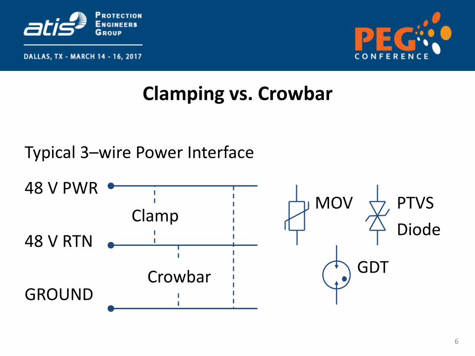
Clamping vs. Crowbar
48 V PWR
48 V RTN
GROUND
Clamp PTVS
Diode
MOV
GDT Crowbar
Typical 3–wire Power Interface
6

Metal Oxide Varistor (MOV) - for power
• A Metal Oxide Varistor (Variable Resistor) is a voltage dependent resistor – resistance decreases with rising voltage
• Prevents damage from transient events by acting as a voltage “clamp”, or limiting voltage to a desired level
7

Metal Oxide Varistor (MOV) - for power
• Pros – Fast response time (10 ns - 25 ns)
– Good clamping performance
– Scale to handle large surges (e.g. 10 kA 8/20)
– Lowest cost (for comparable surges)
• Cons – Current ratings may require multiple MOVs in parallel
– Repeated surges cause wear (leaded disc-type packages) and increase leakage
– While clamping, voltage rises with surge current (less rigid)
(6.5 kA)
8
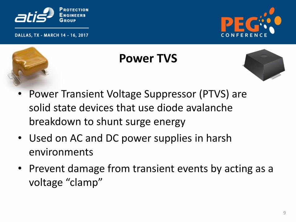
Power TVS
• Power Transient Voltage Suppressor (PTVS) are solid state devices that use diode avalanche breakdown to shunt surge energy
• Used on AC and DC power supplies in harsh environments
• Prevent damage from transient events by acting as a voltage “clamp”
9

Power TVS
• Pros
– Excellent clamping performance – which reduces stress on protected components
– Small solution size, with potential for stand-alone protection
– Solid state, high reliability (no wear out mechanism for rated surges)
– Scale to handle large surges: 3 kA – 15 kA 8/20
• Cons
– Can be damaged if surge rating is exceeded
– Cost increases with surge level 10

MOV vs. PTVS Clamping Performance
PTVS3-076C-TH vs. 1 and 6 MOVs Test Plots (8/20 Surge)
PTVS3-076C-TH exhibits a much better clamp performance than six MOV-10D101K components in parallel. 11

Power TVS Packaging Affects Performance
Through Hole TH
Surface Mount SMD1
Surface Mount SMD2
12

Power TVS Packaging Affects Performance
13
0
20
40
60
80
100
120
140
0
2,000
4,000
6,000
8,000
10,000
12,000
14,000
0 5 10 15 20 25 30 35 40
Vo
ltag
e (
V)
Cu
rre
nt
(A)
Time (µs)
Typical voltage waveforms under 10 kA 8/20 surge
Current
PTVS10-076C-TH
PTVS10-076C-SH
PTVS10-076C-M
Current
TH
SMD1
SMD2

Gas Discharge Tubes
GDTs are an arrangement of electrodes within a gas that operate by ionizing the gas when a sufficient voltage is applied
GDTs prevent damage from transient surges by acting as a “crowbar” or by approximating a short circuit to shunt surge energy, typically to ground
14

Gas Discharge Tubes
• Pros – Handle large surges (e.g. up to 60 kA for 8/20 waveform) – Well understood operation and well characterized – Exhibit low capacitance (e.g. < 2 pf, used on high speed signals) – Also characterized for long duration surges – New smaller, low profile packages
• Cons – Wide tolerance – Reaction time is dependent on the rate of rise of the voltage. – Relatively high let through voltage - rarely afford stand alone
protection – On a DC supply, hold over may occur following a surge
15

GDT Spark Over Specifications
16

Gas Discharge Tube Packaging
17 Similar characteristics

GDTs in Series
• Described in ITU-T Recommendation K.99
• Recent interest from OEM customers considering additional surge withstand requirements
• Bourns Test Board
– Circuit
– Performance
– Coordination with 2nd level of protection (TVS/PTVS)
18

ITU-T Recommendation K.99
Section 8.9 - Series connected GDTs for D.C. power applications 19

GDTs in Series
• After spark over, a single GDT approximates a short circuit – Placed between PWR and RTN, a GDT
would short the power supply output
• A single GDT may not extinguish after a surge (VDC > Varc)
• Positive: Summation of arc voltages – e.g. 5 x 12 V = 60 V
• Negative: Summation of spark-over voltages – e.g. 5 x 150 V = 750 V
1
2
3
4
5
20
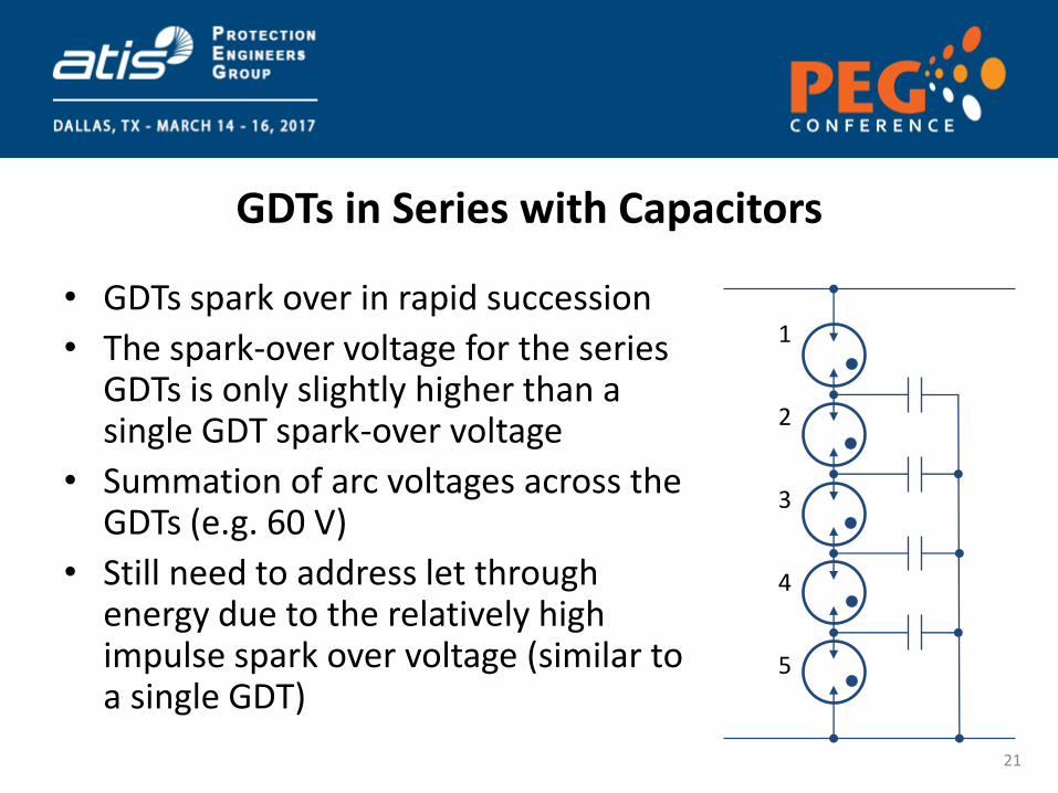
GDTs in Series with Capacitors
• GDTs spark over in rapid succession
• The spark-over voltage for the series GDTs is only slightly higher than a single GDT spark-over voltage
• Summation of arc voltages across the GDTs (e.g. 60 V)
• Still need to address let through energy due to the relatively high impulse spark over voltage (similar to a single GDT)
1
2
3
4
5
21

Bourns Series GDT Test Board
Line Side
(Red)
(Black)
Line Side Return
Series GDTs TVS/ PTVS
Inductor
Protected
(Red)
Protected Return
(Black)
Two layers of protection with inductor as coordination element 22

Bourns Series GDT Test Board
23
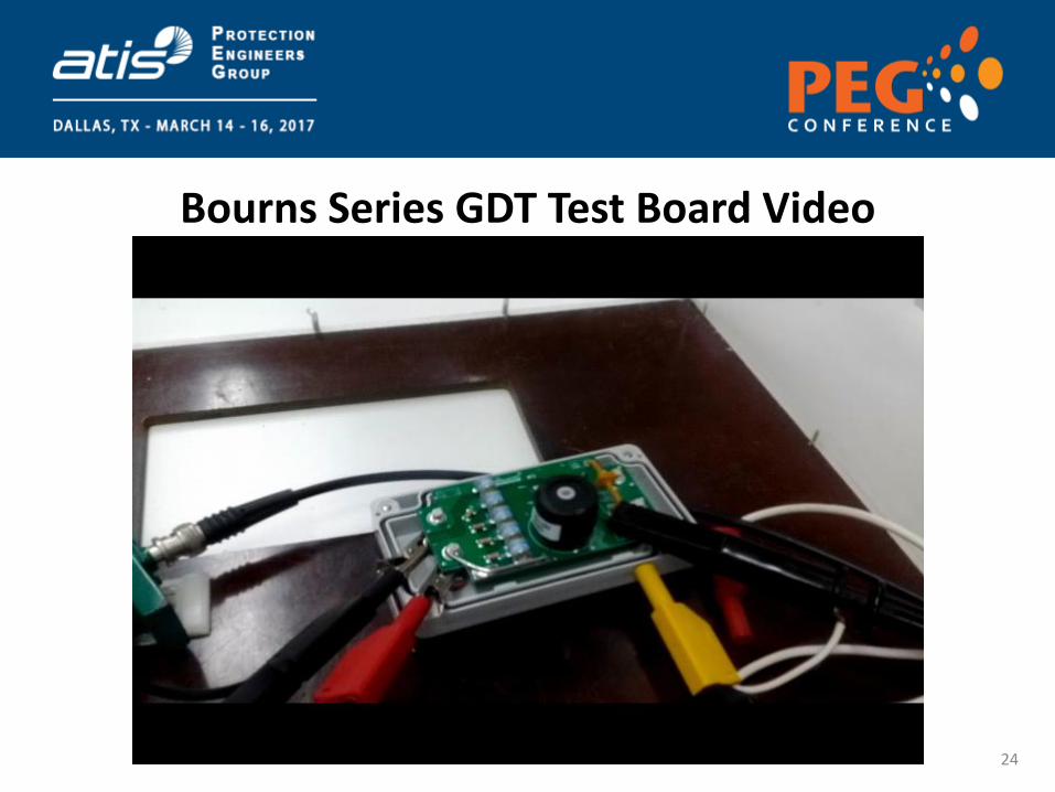
Bourns Series GDT Test Board Video
24
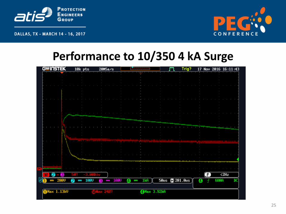
Performance to 10/350 4 kA Surge
25

Test Board Characterization and Performance
• Characterization – In-line resistance, inductance – Line Side to ground impedance, capacitance – 8/20 surge performance (1 kA to 20 kA) – 10/350 surge performance (1 kA to 4 kA) – Inductor temperature rise due to DC (15 A, 20 A) – Inductor temperature rise due to 10/350 4 kA surge
• Test Results – Withstands 8/20 20 kA, and 10/350 4 kA – Good clamping performance for large, fast rising
surges – Slow rising surges increase secondary protection
requirements as GDTs may not spark over
Line Side
Line Side Return
Series GDTs TVS/ PTVS
Inductor
Protected
Protected Return
26
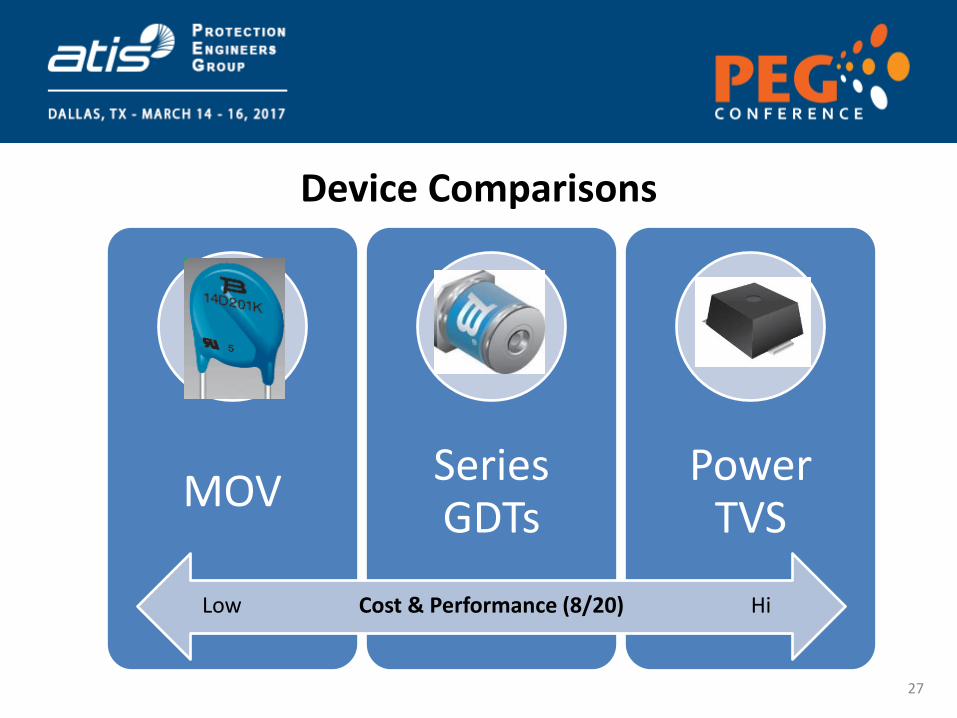
MOV Series GDTs
Power TVS
Cost & Performance (8/20) Low Hi
Device Comparisons
27

MOV
General Information • Multiple MOV • Positives
– Good Clamping – Good Surge Current ratings – Lowest Cost
• Negatives – May require multiple 20mm
MOV to attain high rating – MOV will age and become
leaky under overstress – Large and expensive MOV
required to meet 4 kA 10/350 rating
28

PTVS
General Information • Power TVS • Positives
– Excellent clamping performance – Reliable if maintained within
current specification – TVS a good second stage protector
• Negatives – High cost to achieve 20 kA surge
current rating – Large chip silicon stacks required to
attain Voltage/Current rating – Over surge will kill device
29

General Information • Multi-chamber GDT • Positives
– High Arc voltage allows GDT to reset
– High current ratings – Significant oversurge
required to age device
• Negatives – Poor protection as a
standalone OVP
Series GDTs
30

Hybrid Solutions
• Discrete protection technologies have positive and negative attributes
• Hybrid solutions pair multiple technologies either discrete components or in a module
• Increased level of protection and reliability at an optimal cost
• Parallel stages of protection requires attention to coordination between the stages
31

MOV-GDT
General Information • Multiple MOV+ GDT • Positives
– Good Clamping – Good Surge Current ratings – GDT mitigates leakage
issues and can extend MOV life
• Negatives – Requires multiple 20 mm
MOV to attain high rating – Very large and expensive
MOV required to meet 4 kA 10/350 rating
32

MOV-L-PTVS
General Information • MOV-L-PTVS Hybrid • Positives
– Excellent Clamping of TVS
– Lower cost solution vs. Series GDT hybrid
• Negatives – Larger series resistance
& inductance – MOV still the weak link
in the design
33
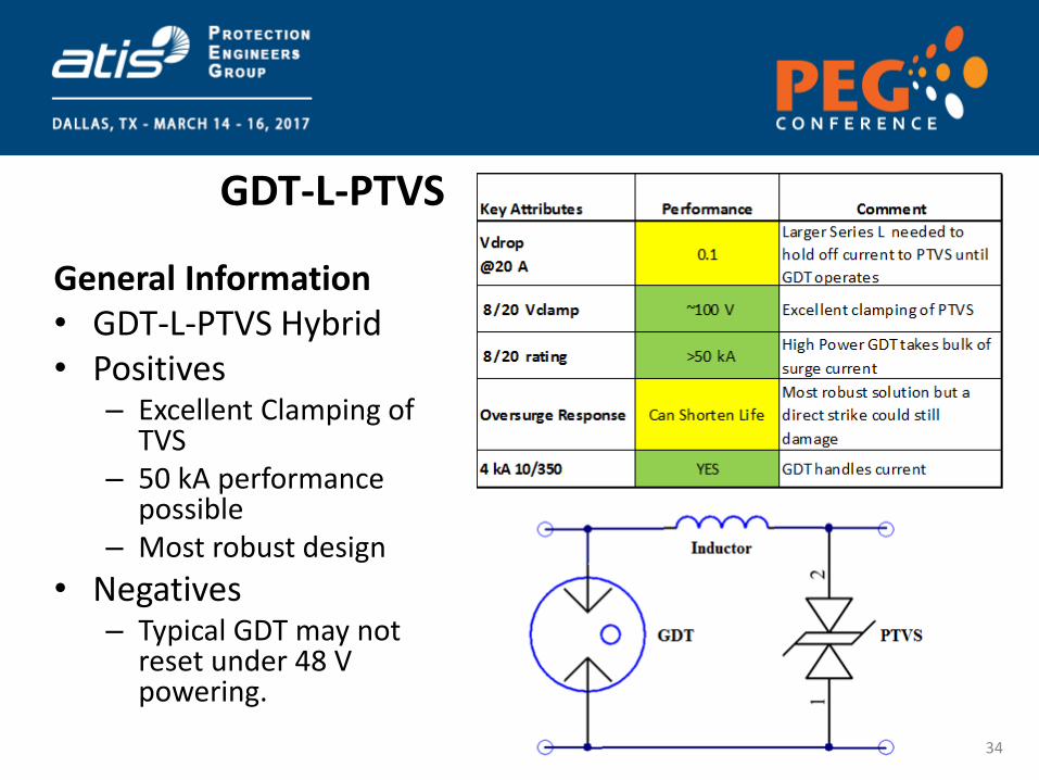
GDT-L-PTVS
General Information • GDT-L-PTVS Hybrid • Positives
– Excellent Clamping of TVS
– 50 kA performance possible
– Most robust design
• Negatives – Typical GDT may not
reset under 48 V powering.
34
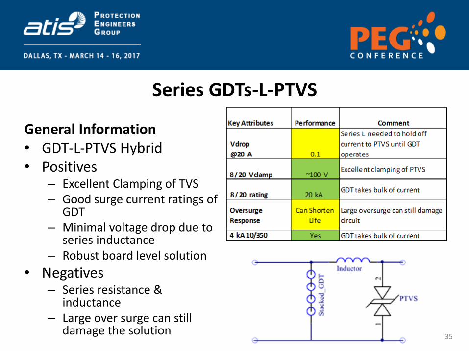
Series GDTs-L-PTVS
General Information • GDT-L-PTVS Hybrid • Positives
– Excellent Clamping of TVS – Good surge current ratings of
GDT – Minimal voltage drop due to
series inductance – Robust board level solution
• Negatives – Series resistance &
inductance – Large over surge can still
damage the solution
35

Summary
• Robust overvoltage protection is being integrated in radio equipment
• Several technologies are available to allow for cost–performance tradeoffs
• Hybrid solutions with proper component selection and coordination have promise and are under study
36


![14-1290 ADQ14 datasheet - トップページ | 組込みボー … DC-offset steps 31 31 Overvoltage protection Absolute max input voltage [V] ±5 (DC level) ±4 – ±4 ... ENOB @](https://img.pdfslide.tips/doc/110x75/5ab9fa897f8b9ab62f8e8204/14-1290-adq14-datasheet-dc-offset-steps.jpg)