Embed Size (px)
Citation preview
A Design Approach for Complex Stiffeners
A. T. Sarawit1, T. Peköz2
ABSTRACT
This paper presents a design approach for laterally braced cold-formed steel flexural
members with edge stiffened flanges other then simple lips. The design method for flexural
members given by Schafer and Peköz (1999) is used here for designing these complex stiffeners.
The method integrates distortional buckling into the unified effective width approach currently
used in most cold-formed steel design specifications. A finite element method was first used to
investigate the post-buckling behavior and carry out initial geometric imperfection sensitivity
studies for various types of stiffeners. Then parametric studies were carried out for different
types of stiffeners to compare the moment capacity determined by the finite element method,
AISI (1996) and the proposed design approach for flexural members given by Schafer and Peköz
(1999).
INTRODUCTION
The following is a summary of the design procedures for flexural members given by
Schafer and Peköz (1999). The design procedures are based on the need for the integration of the
distortional mode into the design procedure. Two behavioral phenomena must be considered.
First, the distortional mode has less post-buckling capacity than the local mode. Second, the
distortional mode has the ability to control failure even when it occurs at a higher critical stress
than the local mode. A design method incorporating these phenomena is needed to provide an
integrated approach to strength prediction involving local and distortional buckling. For
consistency with the existing cold-form steel design specifications an effective width approach
was undertaken. Effective section properties are based on effective widths, b.
()
1 Graduate Research Assistant, School of Civil and Environmental Engineering, Cornell University, Ithaca, NY
14850, U.S.A.2 Professor, School of Civil and Environmental Engineering, Cornell University, Ithaca, NY 14850, U.S.A.
1
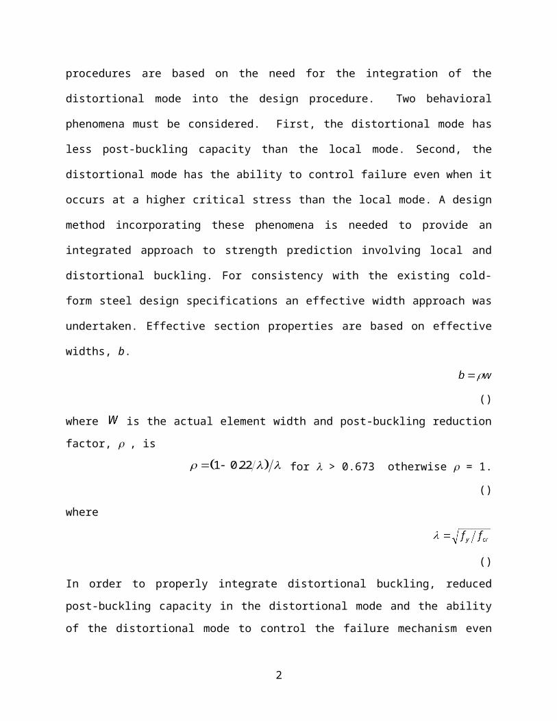
where is the actual element width and post-buckling reduction factor, , is
1 0 22. for > 0.673 otherwise = 1. ()
where
()
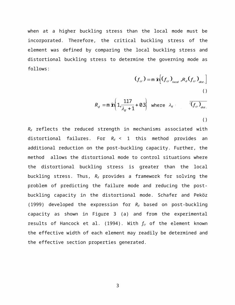
In order to properly integrate distortional buckling, reduced post-buckling capacity in the
distortional mode and the ability of the distortional mode to control the failure mechanism even
when at a higher buckling stress than the local mode must be incorporated. Therefore, the critical
buckling stress of the element was defined by comparing the local buckling stress and
distortional buckling stress to determine the governing mode as follows:
f f R fcr cr local d cr distmin ,
. ()
Rdd
min ,
..1
1171
0 3 where d y cr dist
f f. ()
Rd reflects the reduced strength in mechanisms associated with distortional failures. For Rd < 1
this method provides an additional reduction on the post-buckling capacity. Further, the method
allows the distortional mode to control situations where the distortional buckling stress is greater
than the local buckling stress. Thus, Rd provides a framework for solving the problem of
predicting the failure mode and reducing the post-buckling capacity in the distortional mode.
Schafer and Peköz (1999) developed the expression for Rd based on post-buckling capacity as
shown in Figure 3 (a) and from the experimental results of Hancock et al. (1994). With fcr of the
element known the effective width of each element may readily be determined and the effective
section properties generated.
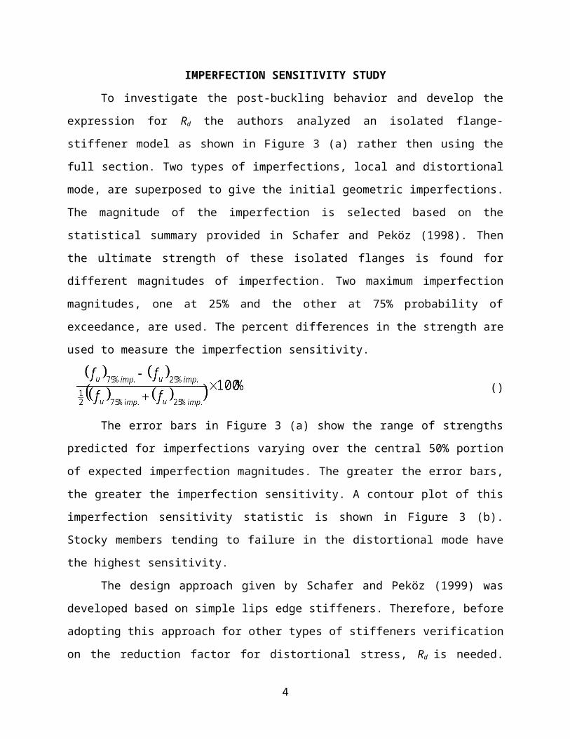
IMPERFECTION SENSITIVITY STUDY
To investigate the post-buckling behavior and develop the expression for Rd the authors
analyzed an isolated flange-stiffener model as shown in Figure 3 (a) rather then using the full
section. Two types of imperfections, local and distortional mode, are superposed to give the
initial geometric imperfections. The magnitude of the imperfection is selected based on the
statistical summary provided in Schafer and Peköz (1998). Then the ultimate strength of these
isolated flanges is found for different magnitudes of imperfection. Two maximum imperfection
magnitudes, one at 25% and the other at 75% probability of exceedance, are used. The percent
differences in the strength are used to measure the imperfection sensitivity.
2
()
The error bars in Figure 3 (a) show the range of strengths predicted for imperfections
varying over the central 50% portion of expected imperfection magnitudes. The greater the error
bars, the greater the imperfection sensitivity. A contour plot of this imperfection sensitivity
statistic is shown in Figure 3 (b). Stocky members tending to failure in the distortional mode
have the highest sensitivity.
The design approach given by Schafer and Peköz (1999) was developed based on simple
lips edge stiffeners. Therefore, before adopting this approach for other types of stiffeners
verification on the reduction factor for distortional stress, Rd is needed. This is done by creating a
post-buckling capacity graph and imperfection sensitivity contour plot on the types of stiffeners
in interest for comparison with the original Figure 3 (a) and 3 (b). In this research 4 types of
complex stiffeners shown in Figure 4 (a), 5 (a), 6 (a) and 7 (a) are studied.
Finite Element Model
In order to study the post-buckling behavior of complex stiffened elements nonlinear
finite element analyses are performed using ABAQUS. To study only the complex stiffened
element behavior an idealization of the boundary conditions at the web/flange junction are made
by restraining all degrees of freedom except for the translation along the length. Roller supports
are used at both ends and to avoid localized failure at the ends the uniform load has been
distributed to the first row of elements. Boundary conditions are shown in Figure 2. The material
model used is elastic-plastic with strain hardening and fy = 347 MPa. Residual stress is also
included with a 30% yield stress throughout the thickness in the longitudinal direction. The
residual stresses are assumed tension on the outside and compression on the inside of the section.
Initial geometric imperfection is introduced by superimposing the eigenmodes for the
local and distortional buckling shown in Figure 1. The magnitude of the imperfection is selected
based on the statistical summary provided in Schafer and Peköz (1998). The length of the model
is selected by using the length that would give the least buckling strength in the distortional
mode, which is obtained, by using the Finite Strip Method CUFSM. Table 1 summarizes the
geometry of the members. An investigation of the post-buckling behavior and an imperfection
3
sensitivity study has been performed for each type of stiffener. Figures 4, 5, 6 and 7 show the
results. For each type of stiffener a total of 42 models were investigated.
It can be seen that the post-buckling capacity graphs and imperfection sensitivity contour
plots are similar to those obtained by simple lips edge stiffened flanges. Therefore, the reduction
factor for distortional stress, Rd is expected to be similar to Schafer and Peköz (1999).
PARAMETRIC STUDIES
Two Z-section parametric studies were carried out for different types of stiffeners to
compare the moment capacity as determined by the finite element method, AISI (1996) and the
proposed design approach for flexural members given by Schafer and Peköz (1999). The first
parameter study consists of different Z-section geometry with all cross sections having the same
thickness while the second parametric study uses one standard Z-section with variation in
thickness. The cross sections selected for both these parameter studies are intend to cover a wide
range of slenderness.
Parametric Study I
The parametric study was carried out by changing different widths of the web, flanges
and stiffeners for five types of stiffeners simple lips, inside angled, outside angled, inside
hooked, and outside hooked stiffeners. All cross sections have the same thickness. Figure 8 (b)-
(f) and Table 2 summarize the geometry of the members. Local and distortional buckling stresses
obtained by the finite strip method are used for the proposed design approach for flexural
members given by Schafer and Peköz (1999).
Finite Element Model
The finite element model used for this parametric study is shown in Figure 9 (a). The
web/flange junction is restrained only for the translation degree of freedom perpendicular to the
length to brace the member laterally. Roller supports are used at both ends. To avoid localized
failure at the ends the constant moment is modeled by nodal loads distributed to the first row of
elements. The material model used is elastic-plastic with strain hardening and fy = 345 MPa.
Residual stress throughout the thickness in the longitudinal direction is assumed to be 30% of the
4
yield stress in the flange and 40% of the yield stress in the web. The residual stresses are also
assumed to be tension on the outside and compression on the inside of the section.
Initial geometric imperfections are introduced by superimposing the eigenmodes for the
local and distortional buckling shown in Figure 9 (b) and (c). Two different imperfection
magnitudes of 75% and 25% probability of exceedance, based on the statistical summary
provided in Schafer and Peköz (1998), are used for each model. The length of the model is
selected by using three half-wave lengths of the distortional mode that gives the least buckling
strength. The wavelengths are obtained using the Finite Strip Method. Figures 10 (a), 11 (a) and
12 (a) summarize the results for the different approaches.
Parametric Study II
The second parametric study was carried out by modifying the stiffeners of a standard
cross section 12ZS3.25, which has a depth of 12 inches, flange width of 3.25 inches and with a
sloping edge stiffener. The sloping stiffener was modified into simple lips, inside angled and
outside angled stiffeners. Figure 8 (a)–(d) summarize the geometry of the members. This was
done for different thicknesses: 0.135, 0.105, 0.090, 0.075 and 0.060 inches. The finite element
assumptions are the same as in the first parameter study except for the yield stress and the lateral
bracing conditions. This study uses a 55 ksi yield stress and instead of fully bracing along the
length as in the first parameter study, only four brace points are used. Brace points included one
at each end and additional ones at one-third of the length, which is the same length as the half-
wave lengths of the distortional mode which gives the least buckling strength. For these cross
sections and bracing lengths, full formation of the distortional mode is still possible without
causing a lateral-torsional failure. Figures 10 (b), 11 (b) and 12 (b) summarize the results for the
different approaches.
SUMMARY AND CONCLUSIONS
Results from the investigation of the post-buckling behavior and imperfection sensitivity
studies on different types of stiffeners suggest that the reduction factor for distortional stress, Rd
given by to Schafer and Peköz (1999) may still be used for stiffeners other then simple lips.
Results from the first and second parametric studies revealed that the AISI (1996)
approach gives unconservative moment capacity while the proposed design approach for flexural
5
members given by Schafer and Peköz (1999) gives a more conservative result closer to the finite
element results. There are no physical test results for these kinds of complex stiffeners. Tests for
members with cross sections such as in Figure 8 are needed to verify this approach. Furthermore,
study of section optimization with complex stiffeners should be conducted.
ACKNOWLEDGEMENT
The sponsorship of the American Iron and Steel Institute and the help of D.L Johnson, Chair of
the AISI Subcommittee in charge of this project, Dr. Helen Chen of the AISI and Dr. B. W.
Schafer are gratefully acknowledged.
REFERENCES
American Iron and Steel Institute, (1996). AISI Specification for the Design of Cold-Formed
Steel Structural Members. American Iron and Steel Institute Washington, D.C.
Peköz, T., (1987). Development of a Unified Approach to the Design of Cold-Formed Steel
Members. American Iron and Steel Institute Research Report CF 87-1.
Schafer, B.W., (1997). “Cold-Formed Steel Behavior and Design: Analytical and Numerical
Modeling of Elements and Members with Longitudinal Stiffeners.” Ph.D. Dissertation,
Cornell University, Ithaca, New York
Schafer, B.W., and Peköz, T.P., (1999). “Laterally Braced Cold-Formed Steel Flexural
Members with Edge Stiffened Flanges.” Journal of Structural Engineering, 125(2)
Schafer, B.W., “CUFSM, Cornell University Finite Strip Method User’s Manual v1.0d” Cornell
University, Ithaca, New York
Table 1 Summary of Isolated Flange-Stiffener Models Geometry*
6
B D a
25 6.25 0, 3.125, 6.25
12.5 0, 6.25, 12.5
50 6.25 0, 3.125, 6.25
12.5 0, 6.25, 12.5
25 0, 12.5, 25
75 6.25 0, 3.125, 6.25
12.5 0, 6.25, 12.5
25 0, 12.5, 25
37.5 0, 18.75, 37.5
100 6.25 0, 3.125, 6.25
12.5 0, 6.25, 12.5
25 0, 12.5, 25
37.5 0, 18.75, 37.5
50 0, 25, 50
*Thickness = 1 mm in all cases
Table 2 Summary of Z-section Models Geometry*
Model H B d a1 50 25 6.25 3.125
2 50 25 6.25 6.25
3 100 25 6.25 3.125
4 100 25 6.25 6.25
5 100 50 6.25 3.125
6 100 50 6.25 6.25
7 100 50 12.5 6.25
8 100 50 12.5 12.5
9 150 25 6.25 3.125
10 150 25 6.25 6.25
11 150 50 6.25 3.125
12 150 50 6.25 6.25
13 150 50 12.5 6.25
14 150 50 12.5 12.5
* Thickness = 1 mm in all cases
Table 3 Summary of Z-section Moment Capacity for Parametric Study I
7
Model Simple lips Inside Angled Outside Angled Inside Hooked Outside HookedM75%
(N-m)
M25%
(N-m)
M75%
(N-m)
M25%
(N-m)
M75%
(N-m)
M25%
(N-m)
M75%
(N-m)
M25%
(N-m)
M75%
(N-m)
M25%
(N-m)
1 718 613 1.027 1.027 709 596 1.055 1.055 702 594 1.062 1.057 710 596 1.056 1.056 710 637 1.024 1.0142 757 691 0.960 0.968 755 635 1.034 1.034 740 654 1.031 0.987 746 630 1.053 1.053 724 617 1.080 1.0333 1665 1551 1.060 0.987 1647 1517 1.081 0.989 1708 1532 1.055 0.931 1616 1503 1.098 0.995 1643 1523 1.081 0.9524 1823 1650 1.008 0.956 1753 1558 1.083 1.012 1764 1583 1.071 0.907 1744 1584 1.080 0.988 1674 1536 1.120 0.9515 1684 1650 1.177 1.052 1556 1536 1.324 1.092 1922 1708 1.128 0.906 1513 1480 1.361 1.114 1498 1488 1.365 1.0956 2174 1845 1.097 0.991 1832 1569 1.265 1.067 2015 1784 1.132 0.886 1703 1602 1.296 1.067 1722 1668 1.263 0.9807 2292 1994 1.032 1.036 2360 2002 1.098 1.042 2371 2008 1.094 0.984 2362 2058 1.086 1.014 2364 2003 1.099 0.9838 2430 2243 0.916 0.961 2470 2059 1.110 1.064 2435 2056 1.120 0.942 2453 2114 1.111 1.047 2433 2080 1.125 0.9459 2719 2544 1.101 0.872 2595 2404 1.162 0.917 2604 2486 1.141 0.883 2623 2442 1.147 0.911 2644 2487 1.132 0.87710 2916 2794 1.040 0.835 2850 2693 1.097 0.863 2702 2544 1.159 0.874 2869 2726 1.089 0.870 2736 2581 1.146 0.86811 2766 2719 1.105 1.005 2709 2688 1.187 0.982 3115 2947 1.057 0.853 2387 2369 1.340 1.105 2430 2361 1.330 1.07912 3160 2815 1.168 1.037 2666 2452 1.323 1.106 2448 2216 1.452 1.132 2522 2371 1.375 1.123 2308 2251 1.476 1.14813 3736 3356 0.983 0.948 3856 3521 1.048 0.920 3777 3567 1.053 0.908 3949 3586 1.028 0.901 3939 3539 1.035 0.89114 3766 3508 0.919 0.958 4130 3696 1.042 0.912 3964 3588 1.080 0.871 4178 3708 1.045 0.911 4041 3547 1.086 0.874
Avg. 1.042 0.974 Avg. 1.136 1.004 Avg. 1.117 0.937 Avg. 1.155 1.011 Avg. 1.169 0.978M75%, M25% – Ultimate moment capacity by finite element method for imperfection magnitudes 75% and 25% probability of exceedanceM50% = (M25%+ M75%)/2MAISI, MPRO - Nominal Moment capacity by AISI and proposed design approach for flexural members given by Schafer and Peköz (1999)
Table 4 Summary of Z-section Moment Capacity for Parametric Study IIThickness Simple lips Simple lips Inside Angled Outside Angled
M75%
(kip-in.)
M25%
(kip-in.)
M75%
(kip-in.)
M25%
(kip-in.)
M75%
(kip-in.)
M25%
(kip-in.)
M75%
(kip-in.)
M25%
(kip-in.)
0.135 436 378 1.150 0.985 433 411 1.133 1.020 420 368 1.231 1.039 420 376 1.219 0.9950.105 262 267 1.247 1.049 283 264 1.250 1.111 269 270 1.288 1.054 257 264 1.336 1.0480.090 194 185 1.397 1.163 221 214 1.276 1.121 213 207 1.375 1.170 192 188 1.518 1.1390.075 141 135 1.404 1.218 170 174 1.192 1.088 149 145 1.425 1.173 141 135 1.523 1.1910.060 94 91 1.452 1.295 122 118 1.213 1.129 112 100 1.366 1.165 97 95 1.505 1.213
Avg. 1.330 1.142 Avg. 1.213 1.094 Avg. 1.337 1.120 Avg. 1.420 1.117
Figure 1 Isolated Flange-Stiffener (a) Local Buckling (b) Distortional Buckling (c) Geometric Imperfection
8
Figure 2 Isolated Flange-Stiffener Boundary Conditions
Figure 3 Simple Lips Stiffener (a) Post-Buckling Capacity (b) Imperfection Sensitivity
Figure 4 Inside Angled Stiffener (a) Post-Buckling Capacity (b) Imperfection Sensitivity
9
y
u
ff
.distcr
localcr
ff
mechanismcry ff mechanismcry ff
y
u
ff
.distcr
localcr
ff
mechanismcry ff mechanismcry ff
(a) (b)
(a) (b)
B
d
a
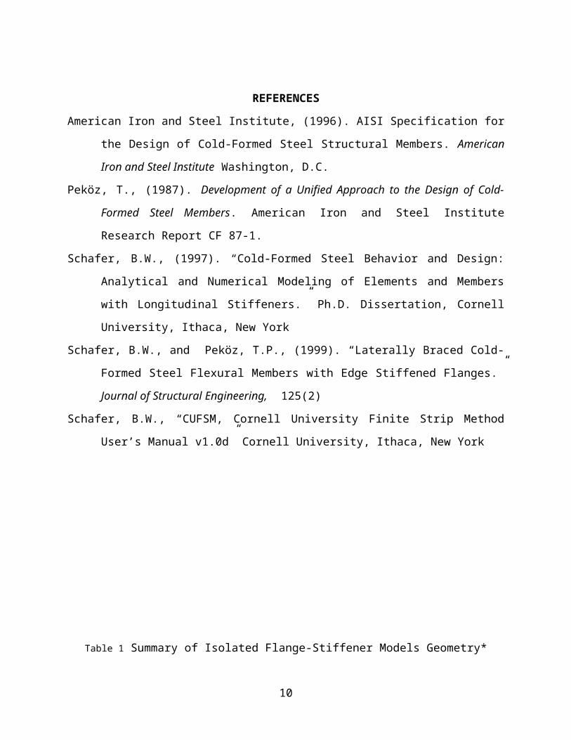
Figure 5 Outside Angled Stiffener (a) Post-Buckling Capacity (b) Imperfection Sensitivity
Figure 6 Inside Hooked Stiffener (a) Post-Buckling Capacity (b) Imperfection Sensitivity
Figure 7 Outside Hooked Stiffener (a) Post-Buckling Capacity (b) Imperfection Sensitivity
10
y
u
ff
.distcr
localcr
ff
mechanismcry ff mechanismcry ff
y
u
ff
.distcr
localcr
ff
mechanismcry ff mechanismcry ff
y
u
ff
.distcr
localcr
ff
mechanismcry ff mechanismcry ff
(a) (b)
(a) (b)
(a) (b)
B
d
a
B
d
d
B
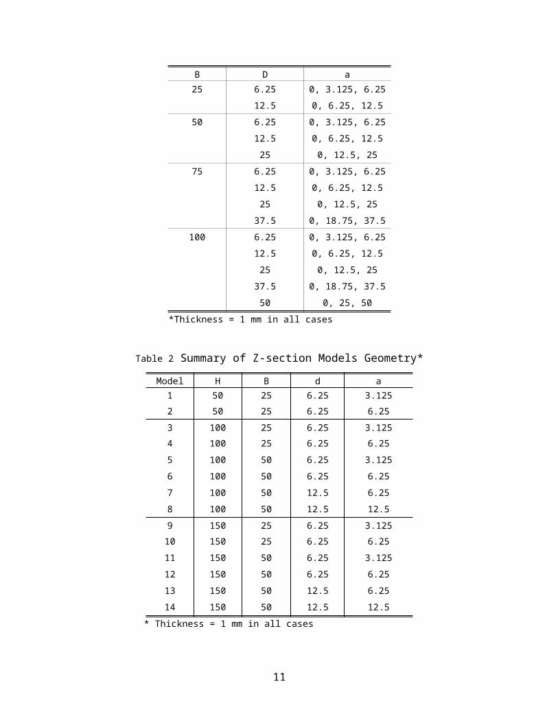
Figure 8 Z-section with (a) Sloping Lips Stiffener 50-degree respect to the flange (b) Simple Lips Stiffener
(c) Inside Angled Stiffener (d) Outside Angled Stiffener (e) Inside Hooked Stiffener (f) Outside Hooked Stiffener
Figure 9 (a) Boundary Conditions (b) Local Buckling (c) Distortional Buckling (d) Initial Geometric Imperfection
11
(a)
(b)
(b)
(d)
H
Bd+a
Bd+a
H
B
d+a
B
d+a
H
B
d
Bd
a
a
H
B
d
B
da
a
H
Bd
Bd
H
B
d
B
d
(a) (b) (c)
(d) (e) (f)
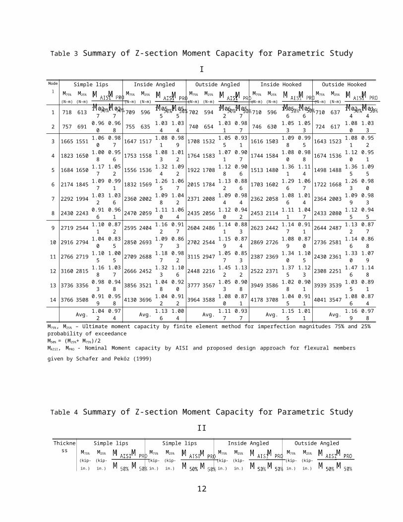
Figure 10 Post-Buckling Capacity by Finite Element Method (a) Parametric Study I (b) Parametric Study II
Figure 11 Post-Buckling Capacity by AISI Method (a) Parametric Study I (b) Parametric Study II
Figure 12 Post-Buckling Capacity by Propose Method (a) Parametric Study I (b) Parametric Study II
12
y
u
MM
mechanismcry MM
y
u
MM
mechanismcry MM
(a) (b)
(a) (b)
y
u
MM
mechanismcry MM
y
u
MM
mechanismcry MM
y
u
MM
mechanismcry MM
y
u
MM
mechanismcry MM
(a) (b)
y
u
MM
mechanismcry MM
y
u
MM
mechanismcry MM