Embed Size (px)
Citation preview

1
Developed by Scott CivjanUniversity of Massachusetts, Amherst

INDIVIDUAL COLUMN
2Compression Theory

Squash LoadFully Yielded Cross Section
3Compression Theory

When a short, stocky column is loaded the strength is limited by the yielding of the entire cross section.
Absence of residual stress, all fibers of cross-section yield simultaneously at P/A=Fy.
P=FyA
yL0P
PL0
4Compression Theory

Results in a reduction in the effective stiffness of the cross section, but the ultimate squash load is unchanged.
Reduction in effective stiffness can influence onset of buckling.
5Compression Theory
RESIDUAL STRESSES

P=FyA
yL0
No Residual Stress
6Compression Theory
With residual stresses, flange tips yield first at P/A + residual stress = Fy
Gradually get yield of entire cross section.
Stiffness is reduced after 1st yield.
RESIDUAL STRESSES

With residual stresses, flange tips yield first at P/A + residual stress = Fy
Gradually get yield of entire cross section.
Stiffness is reduced after 1st yield.
P=FyA
yL0
RESIDUAL STRESSES
7Compression Theory
P=(Fy-Fres)A 1
No Residual Stress
= YieldedSteel
1

With residual stresses, flange tips yield first at P/A + residual stress = Fy
Gradually get yield of entire cross section.
Stiffness is reduced after 1st yield.
P=FyA
yL0
RESIDUAL STRESSES
8Compression Theory
P=(Fy-Fres)A 1
= YieldedSteel
2
No Residual Stress
1
2

With residual stresses, flange tips yield first at P/A + residual stress = Fy
Gradually get yield of entire cross section.
Stiffness is reduced after 1st yield.
P=FyA
yL0
RESIDUAL STRESSES
9Compression Theory
P=(Fy-Fres)A 1
= YieldedSteel
1
2
2
3
3
No Residual Stress

With residual stresses, flange tips yield first at P/A + residual stress = Fy
Gradually get yield of entire cross section.
Stiffness is reduced after 1st yield.
P=FyA
yL0
RESIDUAL STRESSES
Compression Theory
P=(Fy-Fres)A 1
= YieldedSteel
1
2
2
3
3
Effects of Residual Stress
4
104
No Residual Stress

Euler Buckling
11Compression Theory

Assumptions:• Column is pin-ended.• Column is initially perfectly straight.• Load is at centroid.• Material is linearly elastic (no yielding).• Member bends about principal axis (no twisting).• Plane sections remain Plane.• Small Deflection Theory.
12Compression Theory
Euler Buckling

E
P
2
2πLEIPE
Stable Equilibrium
Bifurcation Point
Euler Buckling
P
13Compression Theory

Dependant on Imin and L2.Independent of Fy.
L
PE 2
2πLEIx
2
2πLEI y
Minor axis buckling
For similar unbraced length in each direction, “minor axis” (Iy in a W-shape) will control strength.
14Compression Theory
Major axis buckling
Euler Buckling

PE =
divide by A, PE/A = , then with r2 = I/A,
PE/A = FE =
FE = Euler (elastic) buckling stressL/r= slenderness ratio
2
2πLEI
2
2πAL
EI
22π
rL
E
Re-write in terms of stress:
15Compression Theory
Euler Buckling

Buckling controlled by largest value of L/r.Most slender section buckles first.
L/r
FE
22π
rL
EFy
16Compression Theory
Euler Buckling

EULER ASSUMPTIONS(ACTUAL BEHAVIOR)
17Compression Theory

0 = initial mid-span deflection of column
Initial Crookedness/Out of Straight
P
PM = Po
o
18Compression Theory
o

P
2
2πLEIPE
o= 0
o
19Compression Theory
Initial Crookedness/Out of Straight

P
2
2πLEIPE
o= 0
o
Elastic theory
20Compression Theory
Initial Crookedness/Out of Straight

P
2
2πLEIPE
o= 0
o
Elastic theory
21Compression Theory
Actual Behavior
Initial Crookedness/Out of Straight

Buckling is not instantaneous.
ASTM limits of 0 = L/1000 or 0.25” in 20 feetTypical values are 0 = L/1500 or 0.15” in 20 feet
Additional stresses due to bending of the column, P/A Mc/I.
Assuming elastic material theory (never yields), P approaches PE.
Actually, some strength losssmall 0 => small loss in strengthslarge 0 => strength loss can be substantial
22Compression Theory
Initial Crookedness/Out of Straight

Pe
L
Load Eccentricity
23Compression Theory
P
2
2πLEIPE
o= 0
Elastic theory

Pe
L
Load Eccentricity
24Compression Theory
P
2
2πLEIPE
o= 0
Elastic theory
Actual Behavior

If moment is “significant” section must be designed as a member subjected to combined loads.
Buckling is not instantaneous.
Additional stresses due to bending of the column, P/A Mc/I.
Assuming elastic material theory (never yields), P approaches PE.
Actually, some strength losssmall e => small loss in strengthslarge e => strength loss can be substantial
25Compression Theory
Load Eccentricity

2
2π
eEIP
KL
2
2π
eEIF
KLr
2
2
2
2
)2/1(ππ4
LEI
LEIPE
Similar to pin-pin, with L’ = L/2.Load Strength = 4 times as large.
EXAMPLE
KL
Set up equilibrium and solve similarly to Euler buckling derivation.Determine a “K-factor.”
End Restraint (Fixed)
26Compression Theory

Length of equivalent pin ended column with similar elastic buckling load,
Effective Length = KL
End Restraint (Fixed)
Distance between points of inflection in the buckled shape.
27Compression Theory

Handout on K-factorsEquivalentLength.pdf
28Compression Theory

Fy
ET= Tangent Modulus
E(Fy-Fres)
Test Results from an Axially Loaded Stub Column29Compression Theory
Inelastic Material Effects

KL/r
2
2π
rKL
EFe
Inelastic Material Effects
30Compression Theory
Elastic Behavior

KL/r
2
2π
rKL
EFe
31Compression Theory
Fy-Fres
Fy
2
2π
rKL
EF Tc
Inelastic
Elastic
Inelastic Material Effects

KL/r
2
2π
rKL
EFe
32Compression Theory
Fy-Fres
Fy
2
2π
rKL
EF Tc
Inelastic
Elastic
Inelastic Material Effects

Elastic Buckling: ET = ENo yielding prior to buckling Fe Fy-Fres(max)Fe = predicts buckling (EULER BUCKLING)
Two classes of buckling:
Inelastic Buckling:Some yielding/loss of stiffness prior to bucklingFe > Fy-Fres(max)Fc - predicts buckling (INELASTIC BUCKLING)
33Compression Theory
Inelastic Material Effects

Fy
KL/r
2
2π
rKL
EFE
Experimental Data
Overall Column Strength
34Compression Theory

Fy
KL/r
2
2π
rKL
EFE
Experimental Data
Inelastic Material effects Including Residual Stresses
Out of Straightness
Overall Column Strength
35Compression Theory

Major factors determining strength:1) Slenderness (L/r).2) End restraint (K factors).3) Initial crookedness or load eccentricity.4) Prior yielding or residual stresses.
Overall Column Strength
The latter 2 items are highly variable between specimens.
36Compression Theory

LOCAL BUCKLING
37Compression Theory

Local Buckling is related to Plate Buckling
Flange is restrained by the web at one edge.
Failure is localized at areas of high stress (maximum moment) or imperfections.
38Compression Theory

Local Buckling is related to Plate Buckling
Flange is restrained by the web at one edge.
Failure is localized at areas of high stress (maximum moment) or imperfections.
39Compression Theory

Local Buckling is related to Plate Buckling
Flange is restrained by the web at one edge.
40Compression Theory
Failure is localized at areas of high stress (maximum moment) or imperfections.

Local Buckling is related to Plate Buckling
Failure is localized at areas of high stress (maximum moment) or imperfections.
Web is restrained by the flanges.
41Compression Theory

Local Buckling is related to Plate Buckling
Failure is localized at areas of high stress (maximum moment) or imperfections.
Web is restrained by the flanges.
42Compression Theory

Local Buckling is related to Plate Buckling
Failure is localized at areas of high stress (maximum moment) or imperfections.
Web is restrained by the flanges.
43Compression Theory

FULL STRUCTURE BEHAVIOR
44Compression Theory

ALIGNMENT CHARTOR
DIRECT ANALYSIS METHODS
45Compression Theory

Does not redistribute restraining moments into girders/beams.
ALIGNMENT CHART
“Traditional Method”
Determine effective length, KL,for each column.
Basis for design similar to individual columns.
46Compression Theory

DIRECT ANALYSIS METHOD
Analysis of entire structure interaction.
Include lateral “Notional” loads.
All members must be evaluated under combined axial and flexural load.
No K values required.
Reduce stiffness of structure.
47Compression Theory
ALIGNMENT CHART METHODIS USED FOR THE FOLLOWING
SLIDES
48Compression Theory

ALIGNMENT CHART
“Traditional Method”
Determine effective length, KL,for each column.
Basis for design similar to individual columns.
Does not redistribute restraining moments into girders/beams.
49Compression Theory

K-FACTORS FOR END CONSTRAINTS
No Joint Translation Allowed – Sidesway Inhibited0.5 K 1.0
Joint Translation Allowed – Sidesway Uninhibited1.0 K
50Compression Theory

K-FACTORS FOR END CONSTRAINTS
Behavior of individual column unchanged (Frame merely provides end conditions).
Two categories, Braced Frames, 0.5 K 1.0Sway Frames, K ≥ 1.0
51Compression Theory

Floors do not translate relative to one another in-plane.
Typically, members are pin connected to save cost.
52Compression Theory
Sidesway Prevented

Assume girder/beam infinitely rigid or flexible compared to columns to bound results.
K=0.7K=0.5
K=1K=0.7
Sidesway Prevented
53Compression Theory

Shear Wall
Idealized Equivalent
54Compression Theory
Sidesway Prevented
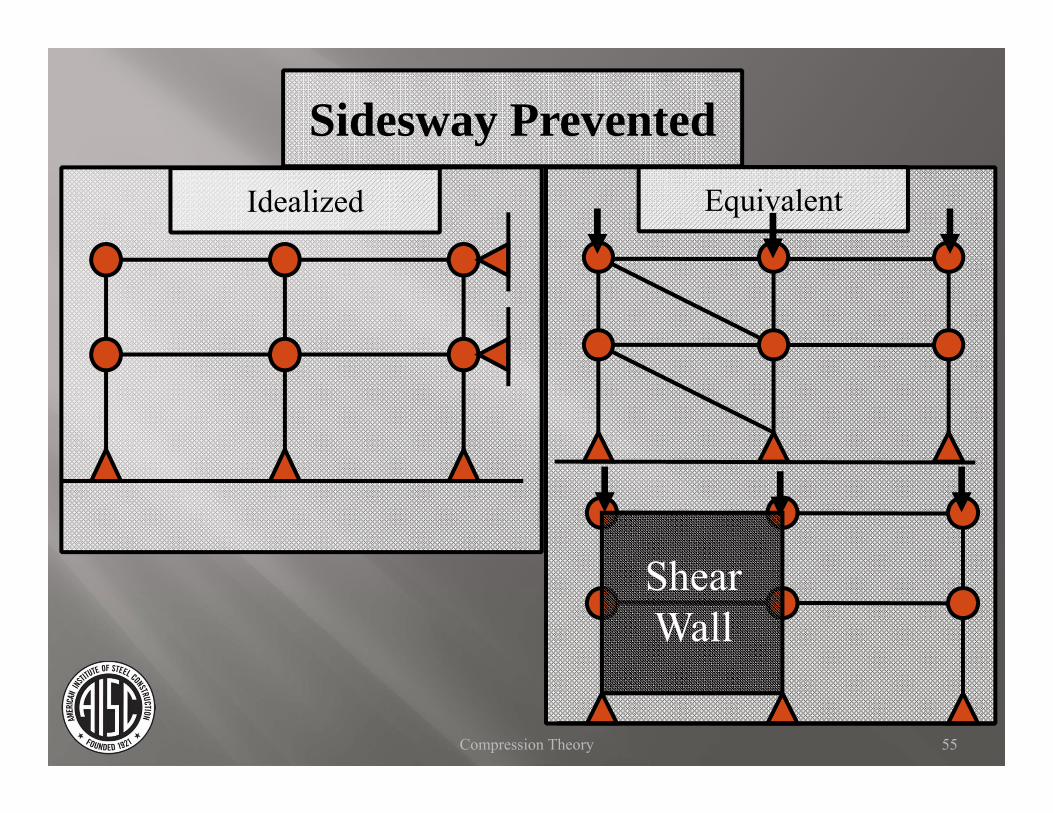
Shear Wall
Idealized Equivalent
55Compression Theory
Sidesway Prevented

Shear Wall
Idealized Equivalent
56Compression Theory
Sidesway Prevented

Typically, members are pin-connected to save cost (K = 1).
If members include fixity at connections, Alignment Chart Method to account for rotational restraint (K < 1).
Typical design will assume K = 1 as a conservative upper bound (actual K ≈ 0.8 not much difference from K = 1 in design).
57Compression Theory
Sidesway Prevented

Floors can translate relative to one another in-plane.
Enough members are fixed to provide stability.
Number of moment frames chosen to provide reasonable force distribution and redundancy.
58Compression Theory
Sway Frame

Assume girder/beam infinitely rigid or flexible compared to columns to bound results.
K=2K=1
K = ∞K=2
Sway Frame
59Compression Theory

Moment Frame
60Compression Theory
Sway Frame

61Compression Theory
Moment Frame
Sway Frame

62Compression Theory
Moment Frame
Sway Frame

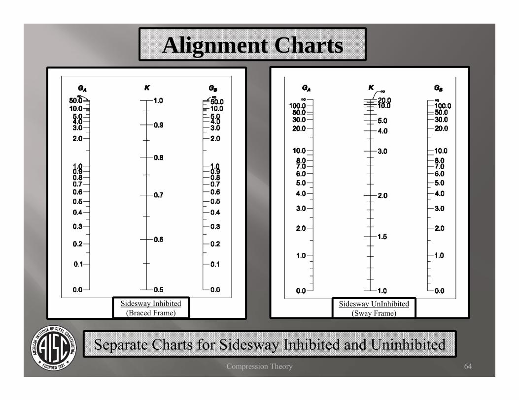
Calculate “G” at the top and bottom of the column (GA and GB).
G is inversely proportional to the degree of rotational restraint at column ends.
I = moment of inertia of the membersL = length of the member between joints
girders
columns
LEILEI
G
63Compression Theory
Alignment Charts
Alignment Charts
Separate Charts for Sidesway Inhibited and Uninhibited
Sidesway Inhibited(Braced Frame)
Sidesway UnInhibited(Sway Frame)
64Compression Theory

Alignment Charts
Separate Charts for Sidesway Inhibited and Uninhibited
Sidesway Inhibited(Braced Frame)
Sidesway UnInhibited(Sway Frame)
65Compression Theory
GtopX
GbottomX
GtopX
GbottomX

Alignment Charts
Separate Charts for Sidesway Inhibited and Uninhibited
Sidesway Inhibited(Braced Frame)
Sidesway UnInhibited(Sway Frame)
66Compression Theory
GtopX
GbottomX
K
K
GtopX
GbottomX

Use the IN-PLANE stiffness Ix if in major axis direction, Iy if in minor axis. Girders/Beams are typically bending about Ixwhen column restraint is considered.
Only include members RIGIDLY ATTACHED (pin ended members are not included in G calculations).
If column base is “pinned” – theoretical G = ∞. AISC recommends use of 10.
If column base is “fixed” – theoretical G = 0. AISC recommends use of 1.
67Compression Theory
Alignment Charts

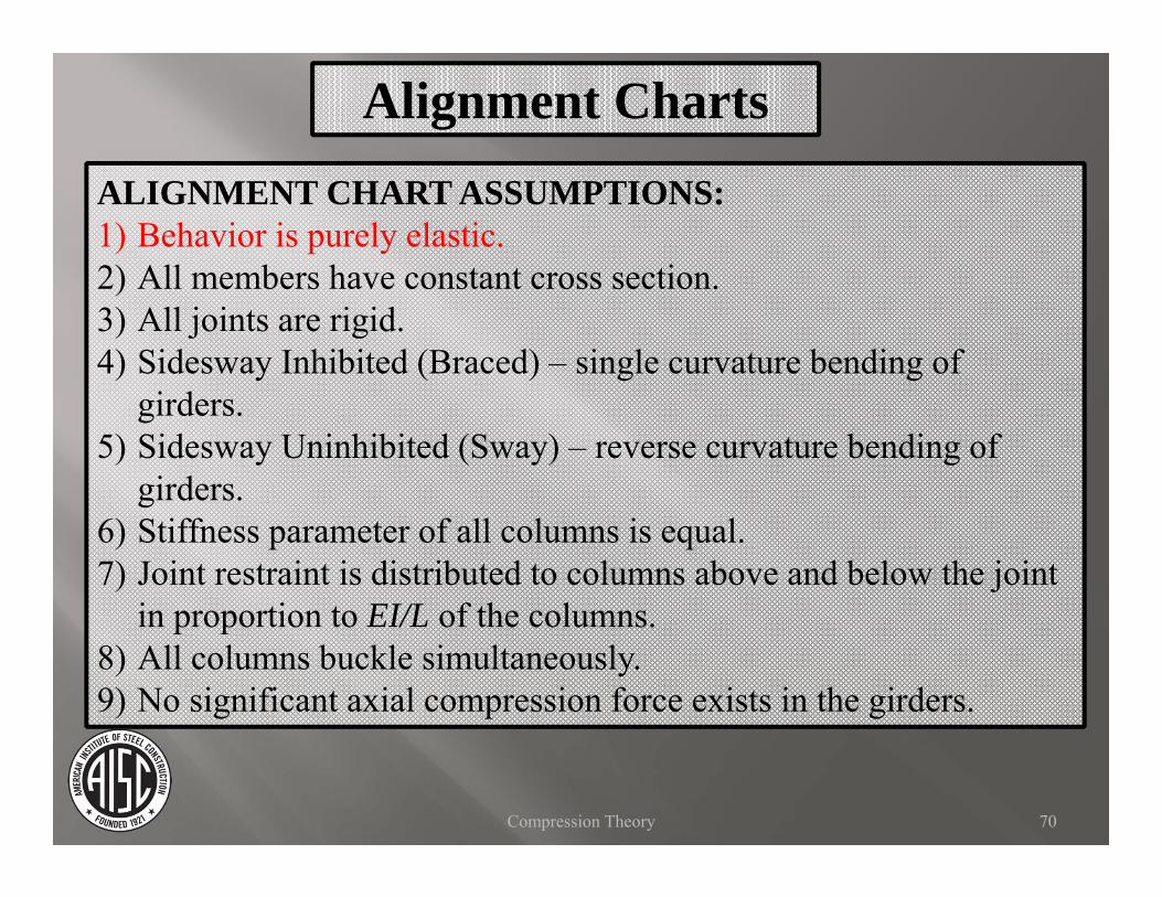
ALIGNMENT CHART ASSUMPTIONS:1) Behavior is purely elastic.2) All members have constant cross section.3) All joints are rigid.4) Sidesway Inhibited (Braced) – single curvature bending of
girders.5) Sidesway Uninhibited (Sway) – reverse curvature bending of
girders.6) Stiffness parameter of all columns is equal.7) Joint restraint is distributed to columns above and below the joint
in proportion to EI/L of the columns.8) All columns buckle simultaneously.9) No significant axial compression force exists in the girders.
68Compression Theory
Alignment Charts

Let’s evaluate the assumptions.
69Compression Theory
Alignment Charts
ALIGNMENT CHART ASSUMPTIONS:1) Behavior is purely elastic.2) All members have constant cross section.3) All joints are rigid.4) Sidesway Inhibited (Braced) – single curvature bending of
girders.5) Sidesway Uninhibited (Sway) – reverse curvature bending of
girders.6) Stiffness parameter of all columns is equal.7) Joint restraint is distributed to columns above and below the joint
in proportion to EI/L of the columns.8) All columns buckle simultaneously.9) No significant axial compression force exists in the girders.
70Compression Theory
Alignment Charts

If the column behavior is inelastic,
Yielding decreases stiffness of the column.
Relative joint restraint of the girders increases.
G therefore decreases, as does K.
Decrease is typically small.
Conservative to ignore effects.
Can account for effects by using a stiffness reduction factor, , times G.
(SRF Table 4-21)71Compression Theory
Alignment Charts

ALIGNMENT CHART ASSUMPTIONS:1) Behavior is purely elastic.2) All members have constant cross section.3) All joints are rigid.4) Sidesway Inhibited (Braced) – single curvature bending of
girders.5) Sidesway Uninhibited (Sway) – reverse curvature bending of
girders.6) Stiffness parameter of all columns is equal.7) Joint restraint is distributed to columns above and below the joint
in proportion to EI/L of the columns.8) All columns buckle simultaneously.9) No significant axial compression force exists in the girders.
72Compression Theory
Alignment Charts

These conditions can be directly accounted for, but are generally avoided in design.
Partial restraint of connections and non-uniform members effectively change the rotational stiffness at the connections.
Only include members RIGIDLY ATTACHED (pin ended members are not included in G calculations).
73Compression Theory
Alignment Charts

ALIGNMENT CHART ASSUMPTIONS:1) Behavior is purely elastic.2) All members have constant cross section.3) All joints are rigid.4) Sidesway Inhibited (Braced) – single curvature bending of
girders.5) Sidesway Uninhibited (Sway) – reverse curvature bending of
girders.6) Stiffness parameter of all columns is equal.7) Joint restraint is distributed to columns above and below the joint
in proportion to EI/L of the columns.8) All columns buckle simultaneously.9) No significant axial compression force exists in the girders.
74Compression Theory
Alignment Charts

Calculation of G accounts for rotational stiffness restraint at each joint based on assumed bending.
girders
columns
LEIm
LEI
G
For other conditions include a correction factor “m” to account for actual rotational stiffness of the girder at the joint.
75Compression Theory
Alignment Charts
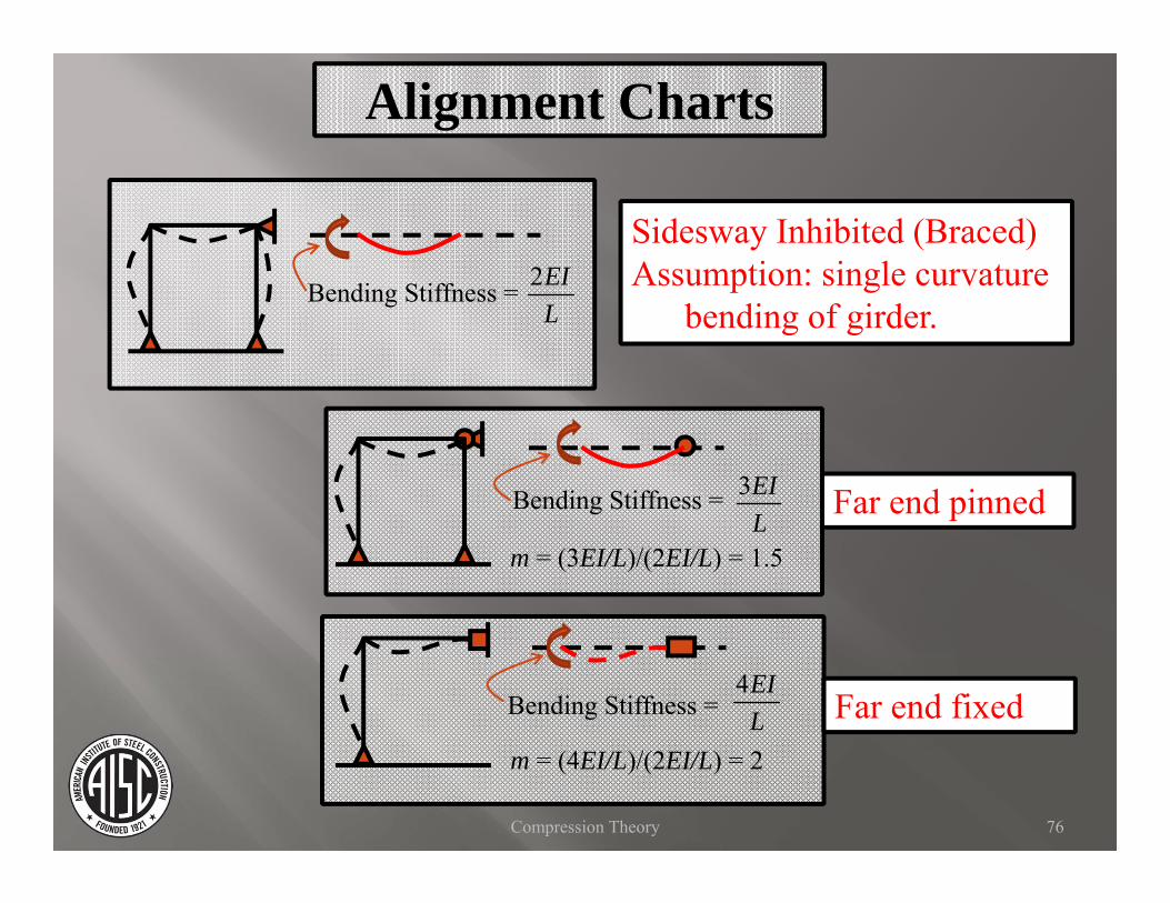
Far end pinned
Bending Stiffness =
Bending Stiffness =
Bending Stiffness =
Sidesway Inhibited (Braced)Assumption: single curvature
bending of girder.
Far end fixed
76Compression Theory
Alignment Charts
2EIL
3EIL
m = (3EI/L)/(2EI/L) = 1.5
m = (4EI/L)/(2EI/L) = 2
4EIL

Far end pinned
Sidesway Uninhibited (Sway)Assumption: reverse curvature
bending of girder.
Far end fixed
Bending Stiffness =
Bending Stiffness =
Bending Stiffness =
77Compression Theory
Alignment Charts
6EIL
3EIL
m = (3EI/L)/(6EI/L) = 1/2
4EIL
m = (4EI/L)/(6EI/L) = 2/3

ALIGNMENT CHART ASSUMPTIONS:1) Behavior is purely elastic.2) All members have constant cross section.3) All joints are rigid.4) Sidesway Inhibited (Braced) – single curvature bending of
girders.5) Sidesway Uninhibited (Sway) – reverse curvature bending of
girders.6) Stiffness parameter of all columns is equal.7) Joint restraint is distributed to columns above and below the joint
in proportion to EI/L of the columns.8) All columns buckle simultaneously.9) No significant axial compression force exists in the girders.
78Compression Theory
Alignment Charts

Design typically checks each story independently, based on these assumptions.
In general, columns are chosen to be a similar size for more than one story. For each column section this results in sections with extra strength in upper floors, and close to their strength in lower floors.
Actual conditions can be directly accounted for, but are generally ignored in design.
79Compression Theory
Alignment Charts

ALIGNMENT CHART ASSUMPTIONS:1) Behavior is purely elastic.2) All members have constant cross section.3) All joints are rigid.4) Sidesway Inhibited (Braced) – single curvature bending of
girders.5) Sidesway Uninhibited (Sway) – reverse curvature bending of
girders.6) Stiffness parameter of all columns is equal.7) Joint restraint is distributed to columns above and below the joint
in proportion to EI/L of the columns.8) All columns buckle simultaneously.9) No significant axial compression force exists in the girders.
80Compression Theory
Alignment Charts

This case will be addressed first, with the concept valid for general conditions as well.
In a story not all columns will be loaded to their full strength.Some are ready to buckle, while others have additional strength.
An extreme case of this is a “leaner” column.
81Compression Theory
Alignment Charts

“LEANER” COLUMNS
82Compression Theory

Leaner Columns
For this structure note that the right columns are pinned at each connection, and provide no bending restraint.Theoretically G at top and bottom is infinite.
83Compression Theory
Moment Frame Leaner Columns

Theoretically the column has an infinite KL.Therefore, the strength should be zero.
For Leaner Columns:G top= InfinityG bottom= InfinityTherefore K= Infinity
KL= Infinite
So the column has no strength according to the alignment chart
84Compression Theory
Leaner Columns

MomentFrame
Leaner Columns
Consider only applying a small load to the right columns
85Compression Theory
Leaner Columns

MomentFrame
Surely a small load could be applied without causing instability! (Due to connection to the rest of the structure)
Leaner Columns
Consider only applying a small load to the right columns
86Compression Theory
Leaner Columns

PA
K = infinity
Pn= zero
PA
K < infinity
Pn> zero
Actual ConditionChart
Provided that the moment frame is not loaded to its full strength, it can provide some lateral restraint to the leaner columns. This is indicated by the spring in the figure above.
87Compression Theory
Leaner Columns

P
Note that the result of a vertical force trying to translate through displacement, is a lateral load of value P/Happlied to the system.
P/H
H
P/H
P
88Compression Theory
Leaner Columns
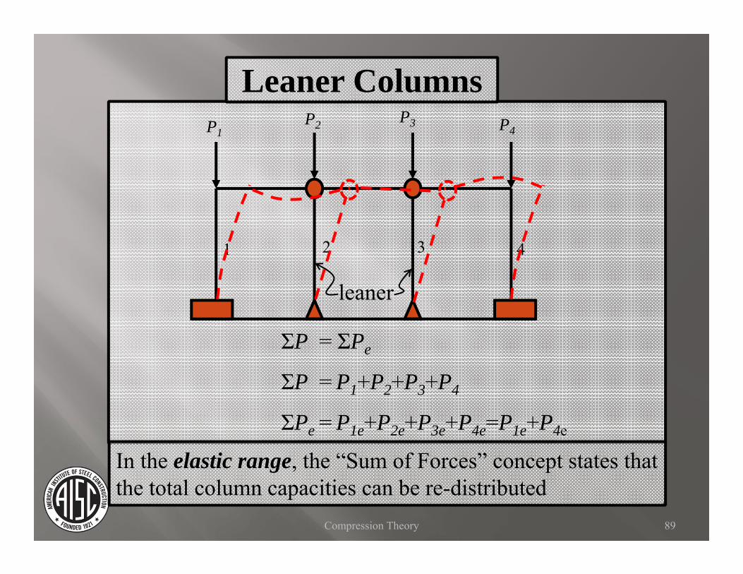
leaner
1 2 3 4
P1P2 P3 P4
ΣP = ΣPe
ΣP = P1+P2+P3+P4
ΣPe = P1e+P2e+P3e+P4e=P1e+P4e
In the elastic range, the “Sum of Forces” concept states that the total column capacities can be re-distributed
89Compression Theory
Leaner Columns

leaner
1 2 3 4
P1P2 P3 P4
If P2 = P2e
Reach failure even if
ΣP < ΣPe
However, the total load on a leaner column still must not exceed the non-sway strength.
90Compression Theory
Leaner Columns

A system of columns for each story should be considered.
Actual design considers inelastic behavior of the sections, but the basic concept is the same.
The strength of the story is the load which would cause all columns to sway.
The strength of an individual column is the load which would cause it to buckle in the non-sway mode (K=1).
91Compression Theory
Leaner Columns

EXAMPLE DEMONSTRATION –SEE YURA VIDEOS
92Compression Theory

Once the limit against lateral buckling and lateral restraint is reached, the entire story will exhibit sidesway buckling.
In general, each story is a system of columns which are loaded to varying degrees of their limiting strength.
Those with additional strength can provide lateral support to those which are at their sidesway buckling strength.
93Compression Theory
Alignment Chart

Alignment ChartALIGNMENT CHART ASSUMPTIONS:1) Behavior is purely elastic.2) All members have constant cross section.3) All joints are rigid.4) Sidesway Inhibited (Braced) – single curvature bending of
girders.5) Sidesway Uninhibited (Sway) – reverse curvature bending of
girders.6) Stiffness parameter of all columns is equal.7) Joint restraint is distributed to columns above and below the joint
in proportion to EI/L of the columns.8) All columns buckle simultaneously.9) No significant axial compression force exists in the girders.
94Compression Theory

Axial load reduces bending stiffness of a section.
In girders, account for this with reduction factor on EI/L.
95Compression Theory
Alignment Chart

If bending load dominates, consider the member a “girder” with reduced rotational stiffness at the joint (axial load reduction).
If axial load dominates, consider member a “column” with extra strength to prevent the story from buckling (sum of forces approach).
It is helpful to think in terms of members controlled by axial force or bending, rather than “girders” and “columns.”
96Compression Theory
Alignment Chart

DIRECT ANALYSIS METHODIS USED FOR THE FOLLOWING
SLIDES
97Compression Theory

DIRECT ANALYSIS METHOD
Analysis of entire structure interaction.
Include lateral “Notional” loads.
No K values required.
Reduce stiffness of structure.
98Compression Theory

DIRECT ANALYSIS METHOD
Further evaluation of this method is included in the module on “Combined Forces.”
99Compression Theory