Embed Size (px)
Citation preview
RAKENNUSTEKNIIKKA Olli Ilveskoski 30.08.2006 rev2 10.01.2007
276
CONNECTIONS
Opiskelija perehtyy liitosten suunnitteluun.ks ESDEP – oppimisympäristö: http://www.terasrakenneyhdistys.fisuomenkielinen versio
CONNECTION DESIGN: STATIC LOADING
Lecture 11.1.1 : Connections in Buildings
Lecture 11.1.2 : Introduction to Connection Design
Lecture 11.2.1 : Generalities on Welded Connections
Lecture 11.2.2 : Welded Connections - Basis for Weld Calculation
Lecture 11.2.3 : Welded Connections - Applications of Fillet Weld Calculation
Lecture 11.3.1 : Connections with Non-Preloaded Bolts
Lecture 11.3.2 : Connections with Preloaded Bolts
Lecture 11.3.3 : Particular Aspects in Bolted Connections
Lecture 11.4.1 : Analysis of Connections I: Basic Determination of Forces
Lecture 11.4.2 : Analysis of Connections: Distribution of Forces in Groups of Bolts and Welds
Lecture 11.4.3 : Analysis of Connections: Transfer of Direct Tension or Compression and Shear
Lecture 11.4.4 : Analysis of Connections: Resistance to Moment by Combined Tension and Compression
Lecture 11.5 : Simple Connections for Buildings
Lecture 11.6 : Moment Connections for Continuous Framing
Lecture 11.7 : Partial Strength Connections for Semi-Continuous Framing
Lecture 11.8 : Splices in Buildings
RAKENNUSTEKNIIKKA Olli Ilveskoski 30.08.2006 rev2 10.01.2007
277
Workgroup Contents
Lecture 11.1.1 : Connections in Buildings
Top
1. INTRODUCTION
2. COMPONENTS OF CONNECTIONS
3. TYPES OF CONNECTIONS
3.1 Column Splices (Figure 8)
3.2 Column Bases (Figure 9)
3.3 Simple Beam-to-Column Connections (Figure 10)
3.4 Moment Resisting Beam-to-Column Connections (Figure11)
3.5 Simple Beam-to-Beam Connections (Figure 12)
3.6 Moment Resisting Beam-to-Beam Connections (Figure13)
3.7 Horizontal Bracing Connections (Figure 14)
3.8 Vertical Bracing Connections (Figure 15)
4. REQUIREMENTS FOR ECONOMY
5. CONCLUDING SUMMARY
6. ADDITIONAL READING
RAKENNUSTEKNIIKKA Olli Ilveskoski 30.08.2006 rev2 10.01.2007
278
Previous | Next | Contents
ESDEP WG 11
CONNECTION DESIGN: STATIC LOADING
Lecture 11.1.1 Connections in Buildings
OBJECTIVE/SCOPE
To identify the ways in which structural connections are made in steel buildings, to discuss the importance of a proper choice of connection type on both overall structural behaviour and economics and to present the basic principles of connection design.
PRE-REQUISITES
Lecture 1B.5.1: Introduction to Design of Simple Industrial Buildings
Lecture 1B.7.1: Introduction to Design of Multi-Storey Buildings
Lecture 3.1.1: General Fabrication of Steel Structures I
Lecture 3.5: Fabrication/Erection of Buildings
RELATED LECTURES
Lecture 11.1.2: Introduction to Connection Design
Lectures 11.2: Welded Connections
Lectures 11.3: Bolted Connections
Lecture 11.4: Analysis of Connections
Lecture 11.5: Simple Connections for Buildings
Lecture 11.6: Moment Connections for Continuous Framing
Lecture 11.7: Partial Strength Connections for Semi-Continuous Framing
Lecture 11.8: Splices
Lectures 13: Tubular Structures
RAKENNUSTEKNIIKKA Olli Ilveskoski 30.08.2006 rev2 10.01.2007
279
SUMMARY
The need for various forms of structural connections in steel buildings is established and their basic forms are identified. Methods of making connections are discussed within the context of transferring local forces between components, ensuring consistency of overall structural behaviour and the practical aspects of fabrication and erection. The basic principles of connection design are thus established.
1. INTRODUCTION
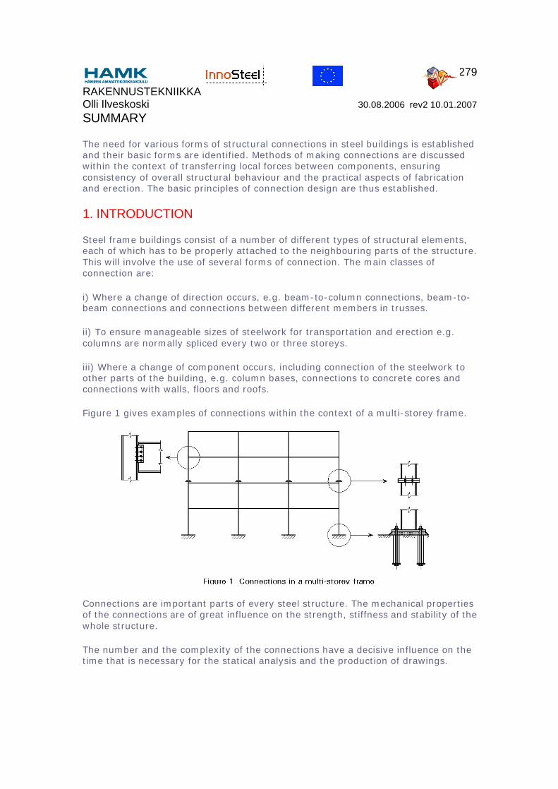
Steel frame buildings consist of a number of different types of structural elements, each of which has to be properly attached to the neighbouring parts of the structure. This will involve the use of several forms of connection. The main classes of connection are:
i) Where a change of direction occurs, e.g. beam-to-column connections, beam-to-beam connections and connections between different members in trusses.
ii) To ensure manageable sizes of steelwork for transportation and erection e.g. columns are normally spliced every two or three storeys.
iii) Where a change of component occurs, including connection of the steelwork to other parts of the building, e.g. column bases, connections to concrete cores and connections with walls, floors and roofs.
Figure 1 gives examples of connections within the context of a multi-storey frame.
Connections are important parts of every steel structure. The mechanical properties of the connections are of great influence on the strength, stiffness and stability of the whole structure.
The number and the complexity of the connections have a decisive influence on the time that is necessary for the statical analysis and the production of drawings.
RAKENNUSTEKNIIKKA Olli Ilveskoski 30.08.2006 rev2 10.01.2007
280
Production of connections, i.e. cutting, drilling and welding of main members, plates, cleats and stiffeners, consumes much of the work content in the fabrication shop. The ease with which the site connections can actually be made is a key factor in erection.
Thus the selection, design and detailing of the connections in a building frame has a very significant influence on costs.
2. COMPONENTS OF CONNECTIONS
Connections in steel structures are normally made using welds and/or bolts.
Welds
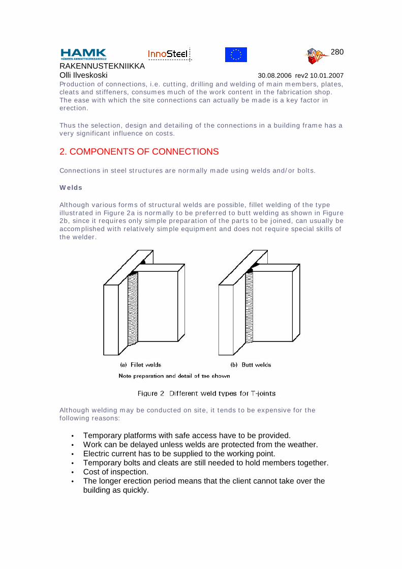
Although various forms of structural welds are possible, fillet welding of the type illustrated in Figure 2a is normally to be preferred to butt welding as shown in Figure 2b, since it requires only simple preparation of the parts to be joined, can usually be accomplished with relatively simple equipment and does not require special skills of the welder.
Although welding may be conducted on site, it tends to be expensive for the following reasons:
• Temporary platforms with safe access have to be provided.• Work can be delayed unless welds are protected from the weather.• Electric current has to be supplied to the working point.• Temporary bolts and cleats are still needed to hold members together.• Cost of inspection.• The longer erection period means that the client cannot take over the
building as quickly.
RAKENNUSTEKNIIKKA Olli Ilveskoski 30.08.2006 rev2 10.01.2007
281
Site joints are, therefore, normally made using bolts.
Bolts
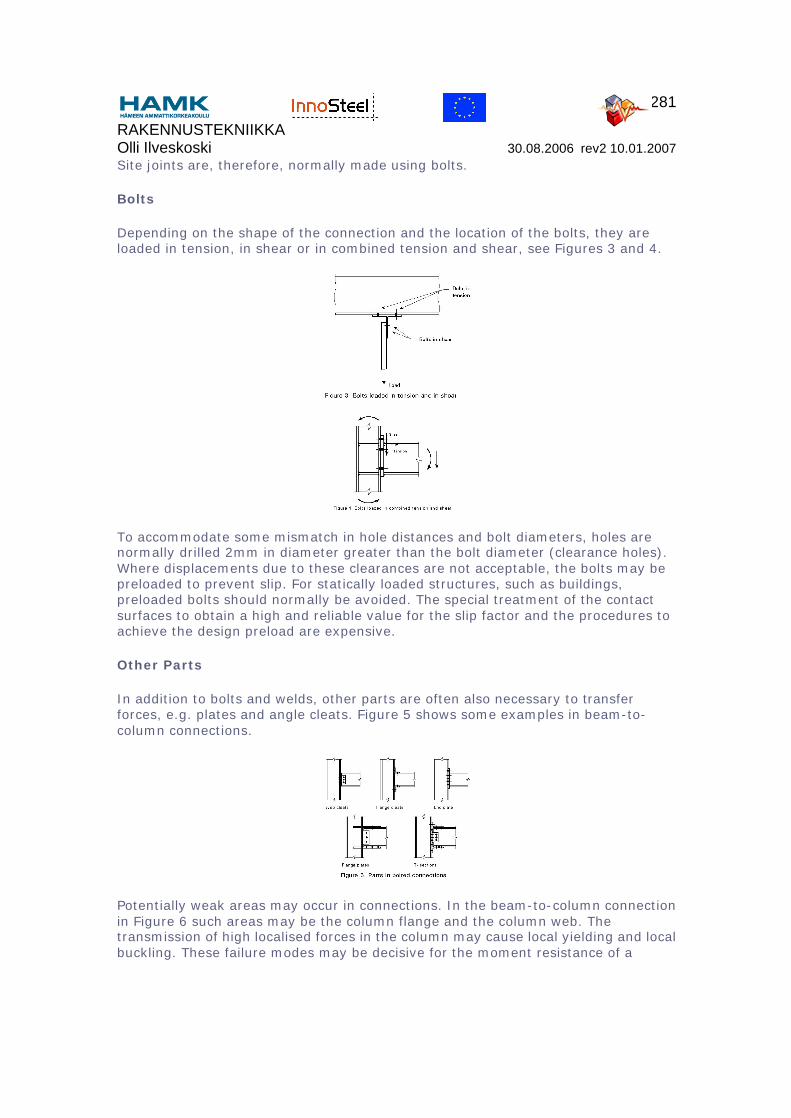
Depending on the shape of the connection and the location of the bolts, they are loaded in tension, in shear or in combined tension and shear, see Figures 3 and 4.
To accommodate some mismatch in hole distances and bolt diameters, holes are normally drilled 2mm in diameter greater than the bolt diameter (clearance holes). Where displacements due to these clearances are not acceptable, the bolts may be preloaded to prevent slip. For statically loaded structures, such as buildings, preloaded bolts should normally be avoided. The special treatment of the contact surfaces to obtain a high and reliable value for the slip factor and the procedures to achieve the design preload are expensive.
Other Parts
In addition to bolts and welds, other parts are often also necessary to transfer forces, e.g. plates and angle cleats. Figure 5 shows some examples in beam-to-column connections.
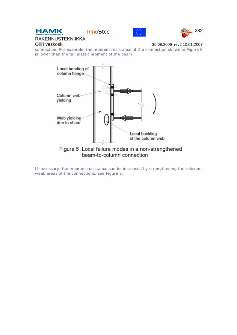
Potentially weak areas may occur in connections. In the beam-to-column connection in Figure 6 such areas may be the column flange and the column web. The transmission of high localised forces in the column may cause local yielding and local buckling. These failure modes may be decisive for the moment resistance of a
RAKENNUSTEKNIIKKA Olli Ilveskoski 30.08.2006 rev2 10.01.2007
282
connection. For example, the moment resistance of the connection shown in Figure 6 is lower than the full plastic moment of the beam.
If necessary, the moment resistance can be increased by strengthening the relevant weak areas of the connections, see Figure 7.
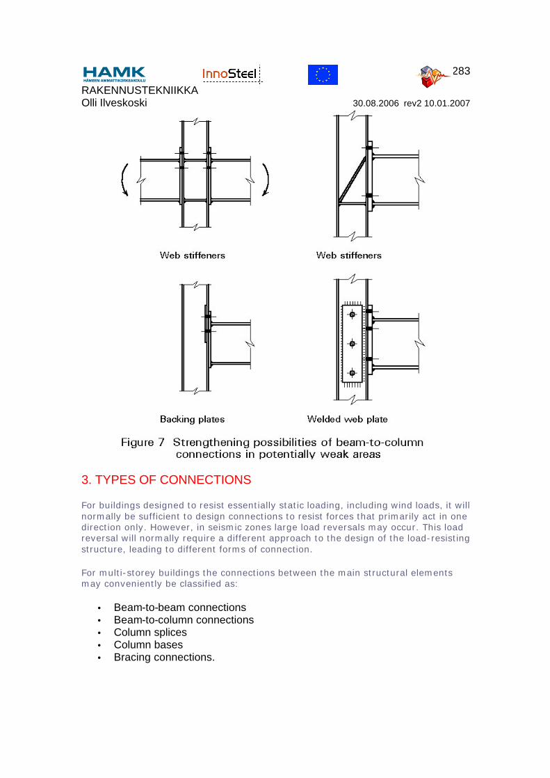
RAKENNUSTEKNIIKKA Olli Ilveskoski 30.08.2006 rev2 10.01.2007
283
3. TYPES OF CONNECTIONS
For buildings designed to resist essentially static loading, including wind loads, it will normally be sufficient to design connections to resist forces that primarily act in one direction only. However, in seismic zones large load reversals may occur. This load reversal will normally require a different approach to the design of the load-resisting structure, leading to different forms of connection.
For multi-storey buildings the connections between the main structural elements may conveniently be classified as:
• Beam-to-beam connections• Beam-to-column connections• Column splices• Column bases• Bracing connections.
RAKENNUSTEKNIIKKA Olli Ilveskoski 30.08.2006 rev2 10.01.2007
284
This list does not, of course, include connections between the main framework and other parts of the structure, e.g. beams to floors, attachment of the cladding, etc. Despite the different geometrical configurations and detailed structural requirements of the five different types, certain general functional requirements must always be addressed:
• The connections should be strong enough to transmit the design loads. To this end, they should be arranged to transmit internal forces from one member to another along smooth load paths so as to avoid severe stress concentrations.
• They must posses the intended degree of flexibility or rigidity.• The connecting elements (plates or cleats) should be arranged such that,
as far as possible, they are self-positioning, accessible for fixing (in the shop and on site), and capable of providing a 'good fit'.
Thus the design of any steelwork connection must simultaneously satisfy the needs of structural adequacy, an appropriate type of behaviour and practical engineering. Clearly it will often be possible that different arrangements satisfy each of these needs to differing degrees. A certain amount of judgement and experience in deciding the relative importance of the different design criteria is required to decide which requirement should be given the greatest emphasis in a given situation. Of course, the designer does not have a completely free choice as he must always ensure that the connection is able to transmit the required level of loads. His choice in this respect relates to the exact arrangement selected and, perhaps, to the extent to which a more easily fabricated connection might provide more strength than is actually required.
In this respect also the workshop should have an influence on the design. Its capabilities and equipment should be taken into consideration when detailing connections. Therefore, the detailing work should be undertaken in consultation with the workshop.
Connections involving tubular members require special care as the arrangements used for open sections may not simply be adapted. The main factor is, of course, the limited access that prevents the use of bolts with nuts inside the tube. In cases where the connections may be made wholly by welding, e.g. shop fabrication of trusses, the solution is clear. However, site joints need particular attention, especially if the clean lines which are often a factor in selecting a tubular configuration are to be preserved. More information is provided in the Lectures in group 13.
In order to give an impression of the wide variety of possible designs, the following descriptions include figures to provide examples of the connection types mentioned above.
RAKENNUSTEKNIIKKA Olli Ilveskoski 30.08.2006 rev2 10.01.2007
285
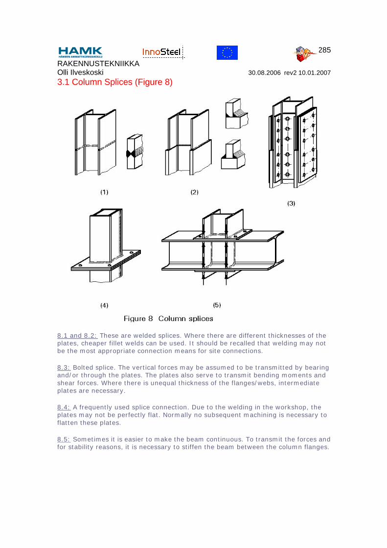
3.1 Column Splices (Figure 8)
8.1 and 8.2: These are welded splices. Where there are different thicknesses of the plates, cheaper fillet welds can be used. It should be recalled that welding may not be the most appropriate connection means for site connections.
8.3: Bolted splice. The vertical forces may be assumed to be transmitted by bearing and/or through the plates. The plates also serve to transmit bending moments and shear forces. Where there is unequal thickness of the flanges/webs, intermediate plates are necessary.
8.4: A frequently used splice connection. Due to the welding in the workshop, the plates may not be perfectly flat. Normally no subsequent machining is necessary to flatten these plates.
8.5: Sometimes it is easier to make the beam continuous. To transmit the forces and for stability reasons, it is necessary to stiffen the beam between the column flanges.
RAKENNUSTEKNIIKKA Olli Ilveskoski 30.08.2006 rev2 10.01.2007
286
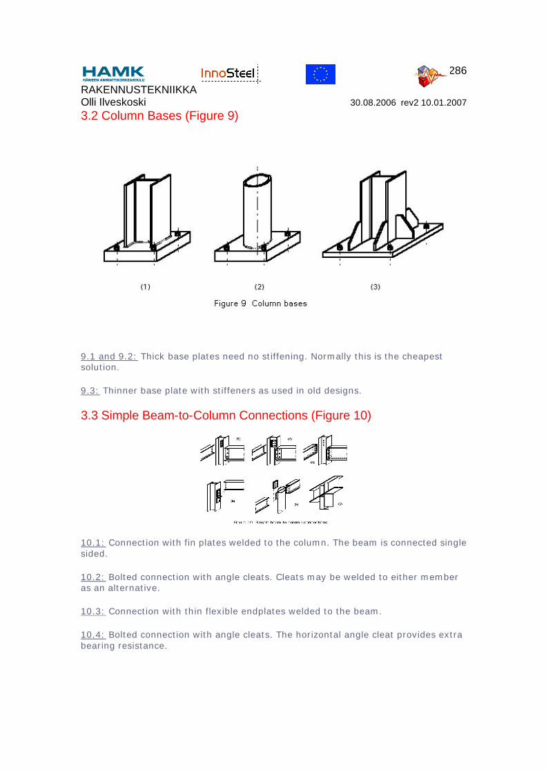
3.2 Column Bases (Figure 9)
9.1 and 9.2: Thick base plates need no stiffening. Normally this is the cheapest solution.
9.3: Thinner base plate with stiffeners as used in old designs.
3.3 Simple Beam-to-Column Connections (Figure 10)
10.1: Connection with fin plates welded to the column. The beam is connected single sided.
10.2: Bolted connection with angle cleats. Cleats may be welded to either member as an alternative.
10.3: Connection with thin flexible endplates welded to the beam.
10.4: Bolted connection with angle cleats. The horizontal angle cleat provides extra bearing resistance.
RAKENNUSTEKNIIKKA Olli Ilveskoski 30.08.2006 rev2 10.01.2007
287
10.5: For a thick wall of a tube, the plates can be welded directly to the wall without making a sleeve in the tube to have a continuous plate. For more details involving tubes, see Lectures 13.
10.6: The stiffness depends largely on the thickness of the end plate on the column and the thickness of the flange of the beam. The stiffening plates may be omitted in many cases.
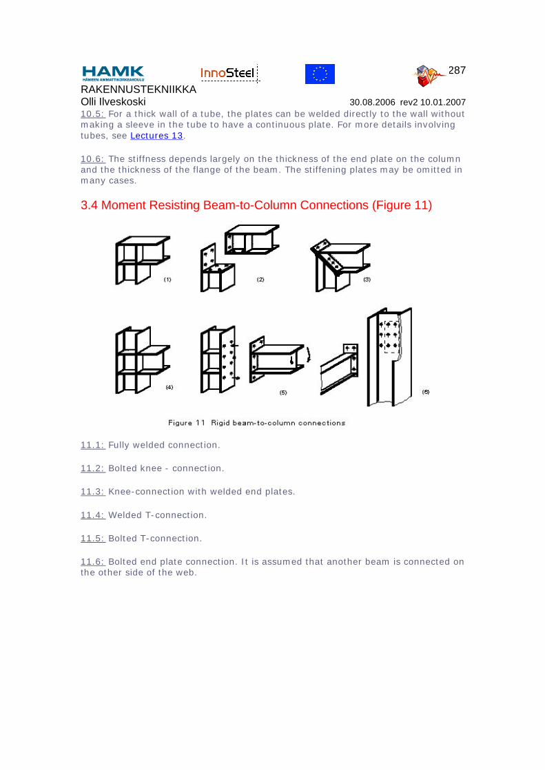
3.4 Moment Resisting Beam-to-Column Connections (Figure 11)
11.1: Fully welded connection.
11.2: Bolted knee - connection.
11.3: Knee-connection with welded end plates.
11.4: Welded T-connection.
11.5: Bolted T-connection.
11.6: Bolted end plate connection. It is assumed that another beam is connected on the other side of the web.
RAKENNUSTEKNIIKKA Olli Ilveskoski 30.08.2006 rev2 10.01.2007
288
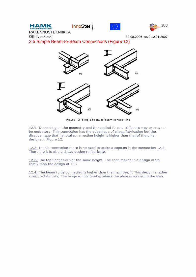
3.5 Simple Beam-to-Beam Connections (Figure 12)
12.1: Depending on the geometry and the applied forces, stiffeners may or may not be necessary. This connection has the advantage of cheap fabrication but the disadvantage that its total construction height is higher than that of the other designs in Figure 12.
12.2: In this connection there is no need to make a cope as in the connection 12.3. Therefore it is also a cheap design to fabricate.
12.3: The top flanges are at the same height. The cope makes this design more costly than the design of 12.2.
12.4: The beam to be connected is higher than the main beam. This design is rather cheap to fabricate. The hinge will be located where the plate is welded to the web.
RAKENNUSTEKNIIKKA Olli Ilveskoski 30.08.2006 rev2 10.01.2007
289
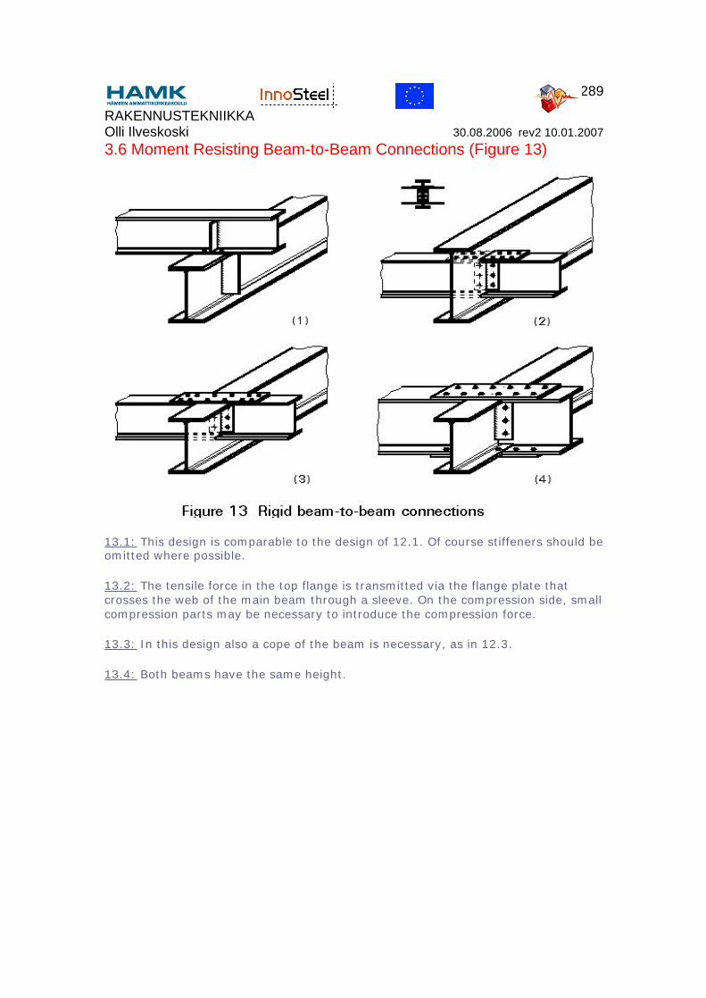
3.6 Moment Resisting Beam-to-Beam Connections (Figure 13)
13.1: This design is comparable to the design of 12.1. Of course stiffeners should be omitted where possible.
13.2: The tensile force in the top flange is transmitted via the flange plate that crosses the web of the main beam through a sleeve. On the compression side, small compression parts may be necessary to introduce the compression force.
13.3: In this design also a cope of the beam is necessary, as in 12.3.
13.4: Both beams have the same height.
RAKENNUSTEKNIIKKA Olli Ilveskoski 30.08.2006 rev2 10.01.2007
290
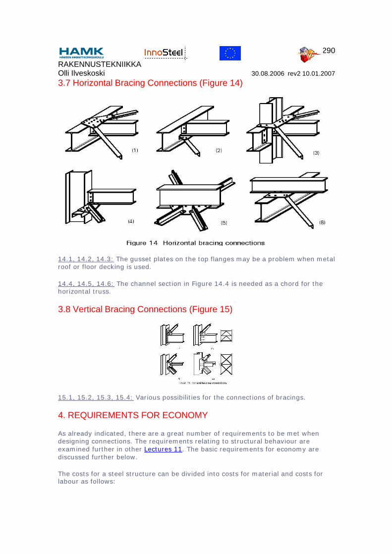
3.7 Horizontal Bracing Connections (Figure 14)
14.1, 14.2, 14.3: The gusset plates on the top flanges may be a problem when metal roof or floor decking is used.
14.4, 14.5, 14.6: The channel section in Figure 14.4 is needed as a chord for the horizontal truss.
3.8 Vertical Bracing Connections (Figure 15)
15.1, 15.2, 15.3, 15.4: Various possibilities for the connections of bracings.
4. REQUIREMENTS FOR ECONOMY
As already indicated, there are a great number of requirements to be met when designing connections. The requirements relating to structural behaviour are examined further in other Lectures 11. The basic requirements for economy are discussed further below.
The costs for a steel structure can be divided into costs for material and costs for labour as follows:

RAKENNUSTEKNIIKKA Olli Ilveskoski 30.08.2006 rev2 10.01.2007
291
Material 20 - 40%Calculation }Drawings }Fabrication } 60 - 80%Protection }Erection. }
From this division of costs it can be concluded that a saving of labour costs has potentially more influence on the overall costs of steel structures than saving on material.
An influencing factor is the relation between cost per kg steel and cost per man hour.
In the past decades the price of steel has increased considerably less than the price of labour. This trend, together with developments in fabrication technology, means that structural designs that were optimal 10 years ago may not be competitive now.
A major part of labour costs has a direct relation to the design and fabrication of connections. It is often better in design to save labour at the expense of material. This fact can be illustrated with some simple examples. To estimate the costs, the following assumptions are made:
• the costs for 1cm3 of weld is equivalent to 0,7 kg of steel.• the costs for fabrication of stiffening plates are equal to the welding costs.• the costs per hole are equivalent to 2 kg of steel.
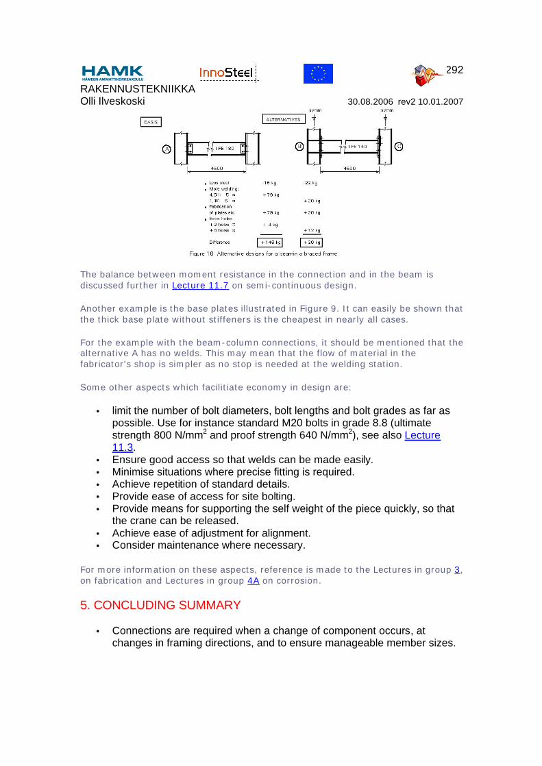
In Figure 16 a beam in a braced frame is given. The basis is a design with simple connections to transmit shear force only. When the "hinges" are replaced by moment connection as in [B] and [C], then for the beam an IPE 140 can be selected instead of an IPE 180. However, due to the extra costs for the connections, the alternatives [B] and [C] are more expensive, especially [B]. The difference with [C] which uses backing plates to strengthen the column flanges is less. When the same exercise is carried out for a beam with greater span, e.g. 10m, it is found that alternative C is the cheapest.
RAKENNUSTEKNIIKKA Olli Ilveskoski 30.08.2006 rev2 10.01.2007
292
The balance between moment resistance in the connection and in the beam is discussed further in Lecture 11.7 on semi-continuous design.
Another example is the base plates illustrated in Figure 9. It can easily be shown that the thick base plate without stiffeners is the cheapest in nearly all cases.
For the example with the beam-column connections, it should be mentioned that the alternative A has no welds. This may mean that the flow of material in the fabricator's shop is simpler as no stop is needed at the welding station.
Some other aspects which facilitiate economy in design are:
• limit the number of bolt diameters, bolt lengths and bolt grades as far as possible. Use for instance standard M20 bolts in grade 8.8 (ultimate strength 800 N/mm2 and proof strength 640 N/mm2), see also Lecture 11.3.
• Ensure good access so that welds can be made easily. • Minimise situations where precise fitting is required.• Achieve repetition of standard details.• Provide ease of access for site bolting.• Provide means for supporting the self weight of the piece quickly, so that
the crane can be released.• Achieve ease of adjustment for alignment.• Consider maintenance where necessary.
For more information on these aspects, reference is made to the Lectures in group 3, on fabrication and Lectures in group 4A on corrosion.
5. CONCLUDING SUMMARY
• Connections are required when a change of component occurs, at changes in framing directions, and to ensure manageable member sizes.
RAKENNUSTEKNIIKKA Olli Ilveskoski 30.08.2006 rev2 10.01.2007
293
• Connections must satisfy the requirements of structural behaviour. They should be strong enough to transmit the design loads and at the same time have the intended degree of flexibility or rigidity.
• Connection design has a major influence on the costs of real structures.• Two types of fasteners are used for connections - welds and bolts.• Normally welding is applied in the fabrication shop and bolts are used for
erection.• When detailing connections, thought should be given to fabrication
practicalities and erection sequence and method.
6. ADDITIONAL READING
1. Boston, R.M. and Pask, J.W. 'Structural Fasteners and their Applications', BCSA 1978.
Drawings of bolts of all kinds and photographs of fixings procedures, plus examples of connection design.
2. Interfaces: Connections between Steel and other Materials, Ove Arup and Partners. Edited by R. G. Ogden, 1994.
3. Hogan, T.J. and Firkins, A., 'Standardized structural connections', Australian Institute of Steel Construction, 1981, 3rd Ed, 1985.
Presents design models and resistance tables for the main connection types.
4. Blodgett, O.W., 'Design of welded structures', James F Lincoln Arc Welding Foundation, Cleveland, Ohio, USA, 1972.
Informative and well illustrated reference manual covering all aspects of welded design and construction.
5. Ballio, G. and Mazzolani, F.M., 'Theory and design of steel structures', Chapman and Hall, London, 1983.
Comprehensive text on theory and design of steel structures. Deals extensively with connections. A detailed treatment of combined loads on fillet welds is of particular interest.
6. Draft for Development DD ENV 1993-1-1: 1992 Eurocode 3: Design of Steel Structures, Part 1, General Rules and Rules for Buildings.
Chapter 6 presents rules covering the design of individual items of connections, e.g. bolts, welds, hole edge distances, etc. Annex J deals in more detail with the design of bolted and welded beam-to-column connections.
RAKENNUSTEKNIIKKA Olli Ilveskoski 30.08.2006 rev2 10.01.2007
294
7. Essentials of Eurocode 3, Design Manual for Structures in Buildings, ECCS Publication 65, 1991.
8. Bijlaard, F.S.K. et al, Structural Properties of Semi-Rigid Joints in Steel Frames, IABSE Publications, 1989.
Explains how flexibility arises in beam-to-column connections and presents methods for assessing stiffness and strength properties.
9. Joints in simple construction, Volume 1: Design methods,
SCI/BCSA Publication 205, 2nd Ed, 1993.
Provides design models and some background for the most popular types of: beams to columns, beam to beam, column splice and column base.
10.Joints in Simple Construction, Volume 2: Practical Applications, SCI/BCSA Pub 206, 1st Ed, 1992.
Expands on the more practical aspects of connection design; provides tables to facilitate connection design in a "look-up" basis.
11.Owens, G. W. and Cheal, B. D., Structural Steelwork Connections, 1st Ed, 1989.
Comprehensive coverage of many aspects of connection behaviour and design.
RAKENNUSTEKNIIKKA Olli Ilveskoski 30.08.2006 rev2 10.01.2007
295
ESDEP WG 11
CONNECTIONS DESIGN: STATIC LOADING
Lecture 11.2.2: Welded Connections - Basis for Weld Calculation
OBJECTIVE/SCOPE:
To present the general methods for conducting calculations to determine the strength of butt and fillet welds.
PREREQUISITES:
Lectures 1B.5: Introduction to Design of Buildings
Lecture 2.1: Characteristics of Iron-Carbon Alloys
Lecture 2.3: Engineering Properties of Steels
Lecture 3.2: Erection
Lecture 3.5: Fabrication/Erection of Buildings
Lecture 3.6: Inspection/Quality Assurance
Lecture 11.1.2: Introduction to Connection Design
Lecture 11.2.1: Generalities on Welded Connections
RELATED LECTURES:
Lecture 2.4: Steel Grades and Qualities
Lecture 2.6: The Weldability of Structural Steels
Lecture 3.3: Principles of Welding
Lecture 3.4: Welding Processes
Lectures 11.4: Analysis of Connections
SUMMARY:
The bases for the calculation of weld strength are set out. A large part of the lecture deals with the actual stress distribution and the deformability of fillet and butt welds.
RAKENNUSTEKNIIKKA Olli Ilveskoski 30.08.2006 rev2 10.01.2007
296
Some experimental results are presented to show the relevance of the design formulae.
NOTATION
a throat thickness of weld [mm]
F external force [N]
Fσ⊥ normal force perpendicular to the plane of the throat area of the weld [N]
Fτ⊥ shear force in the plane of the throat area transverse to the weld axis [N]
Fτ// shear force in the plane of the throat area parallel to the weld axis [N]
fu nominal ultimate tensile stress of parent metal [MPa]
fvw design shear strength of weld [MPa]
Lj length of lap joint [mm]
Lw length of weld (in long joint) [m]
l length of weld [mm]
βw correlation factor
βLW reduction factor for long weld
γMW partial safety factor for welds
σ1 normal stress perpendicular to the plane of the throat area of the weld [MPa]
σ2 normal stress parallel to the axis of the weld [MPa]
σeq equivalent stress [MPa]
τ1 shear stress in the plane of the throat area transverse to the weld axis [MPa]
τ2 shear stress in the plane of the throat area parallel to the weld axis [MPa]
1. INTRODUCTION
The purpose of this lecture is to present the basis for weld strength calculation according to Eurocode 3 [1], to discuss the assumptions on which the methods are based and to examine the general methods used to determine stresses in welds. In practice, weld calculations are principally concerned with fillet welds since these
RAKENNUSTEKNIIKKA Olli Ilveskoski 30.08.2006 rev2 10.01.2007
297
account for approximately 80% of all structural welds. For this reason the lecture concentrates on fillet welds and gives less attention to other weld types (butt, slot, plug).
For weld design, three fundamental assumptions are made [2]:
• The welds are homogeneous and isotropic elements.• The parts connected by the welds are rigid and their deformations are
negligible.• Only nominal stresses due to external loads are considered. Effects of
residual stresses, stress concentrations and shape of the welds are neglected in static design.
These assumptions lead to a uniform stress distribution in the weld, whereas variation of stress and strain are observed along the weld. In fact, stress concentrations and residual stresses can reach the yield stress locally. However, the ductility of the material leads to a redistribution of stresses along the weld length,producing an appreciable reduction of stress magnitude. The redistribution also occurs when the weld is subject to the action of external loads. According to the theory of plasticity, the final stress distribution will be optimum when the yield stress is reached over the full length of the weld.
Eurocode 3 [1] specifies that the filler metal shall have mechanical properties (yield strength, ultimate tensile strength, elongation at failure and minimum Charpy V-notch energy value) equal to, or better than, the corresponding properties of the parent material. Therefore, for weld calculation and design, the strength of the parent material is normally taken as the reference strength.
Although fillet welds are the more important case, butt welds are treated first since the design requirements are simpler.
2. BUTT WELD CALCULATION
Providing the welding process has been correctly carried out, the butt weld filler metal may be considered as parent metal. Hence, to determine the resistance of the joint, the calculation is based on the throat area, i.e. the penetration area. Depending on the penetration, two kinds of butt welds are defined: full and partial penetration welds.
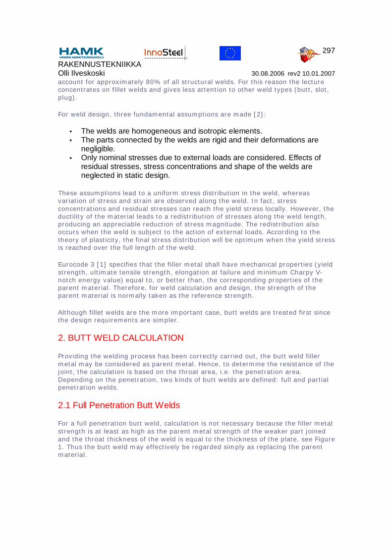
2.1 Full Penetration Butt Welds
For a full penetration butt weld, calculation is not necessary because the filler metal strength is at least as high as the parent metal strength of the weaker part joined and the throat thickness of the weld is equal to the thickness of the plate, see Figure 1. Thus the butt weld may effectively be regarded simply as replacing the parent material.
RAKENNUSTEKNIIKKA Olli Ilveskoski 30.08.2006 rev2 10.01.2007
298
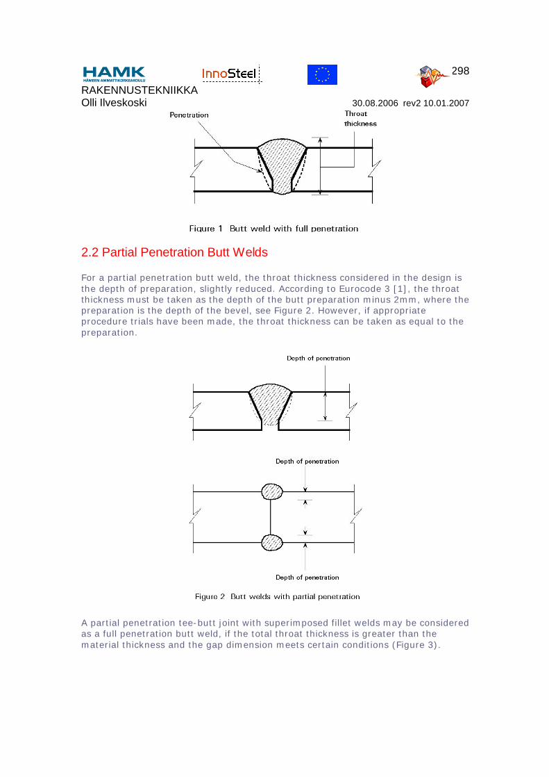
2.2 Partial Penetration Butt Welds
For a partial penetration butt weld, the throat thickness considered in the design is the depth of preparation, slightly reduced. According to Eurocode 3 [1], the throat thickness must be taken as the depth of the butt preparation minus 2mm, where the preparation is the depth of the bevel, see Figure 2. However, if appropriate procedure trials have been made, the throat thickness can be taken as equal to the preparation.
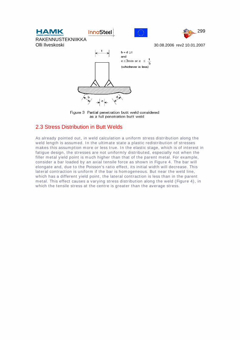
A partial penetration tee-butt joint with superimposed fillet welds may be considered as a full penetration butt weld, if the total throat thickness is greater than the material thickness and the gap dimension meets certain conditions (Figure 3).
RAKENNUSTEKNIIKKA Olli Ilveskoski 30.08.2006 rev2 10.01.2007
299
2.3 Stress Distribution in Butt Welds
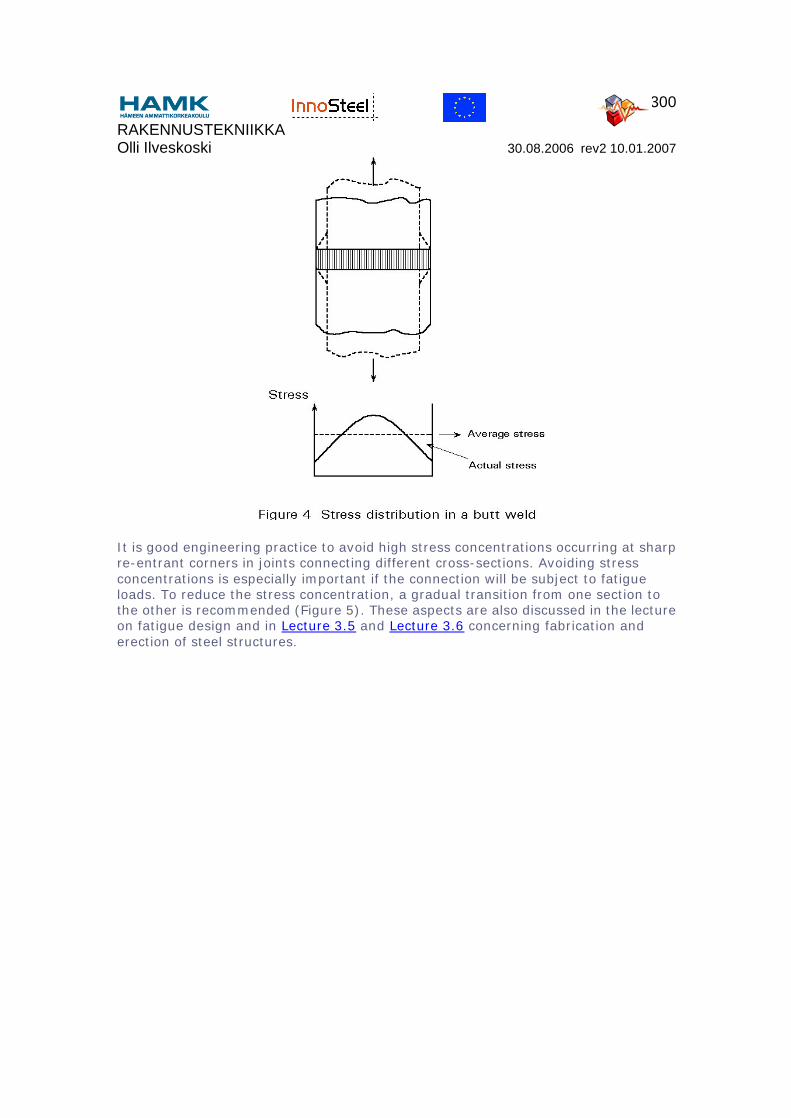
As already pointed out, in weld calculation a uniform stress distribution along the weld length is assumed. In the ultimate state a plastic redistribution of stresses makes this assumption more or less true. In the elastic stage, which is of interest in fatigue design, the stresses are not uniformly distributed, especially not when the filler metal yield point is much higher than that of the parent metal. For example, consider a bar loaded by an axial tensile force as shown in Figure 4. The bar will elongate and, due to the Poisson's ratio effect, its initial width will decrease. This lateral contraction is uniform if the bar is homogeneous. But near the weld line, which has a different yield point, the lateral contraction is less than in the parent metal. This effect causes a varying stress distribution along the weld (Figure 4), in which the tensile stress at the centre is greater than the average stress.
RAKENNUSTEKNIIKKA Olli Ilveskoski 30.08.2006 rev2 10.01.2007
300
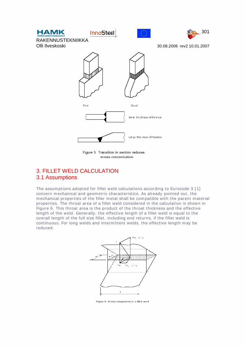
It is good engineering practice to avoid high stress concentrations occurring at sharp re-entrant corners in joints connecting different cross-sections. Avoiding stress concentrations is especially important if the connection will be subject to fatigue loads. To reduce the stress concentration, a gradual transition from one section to the other is recommended (Figure 5). These aspects are also discussed in the lecture on fatigue design and in Lecture 3.5 and Lecture 3.6 concerning fabrication and erection of steel structures.
RAKENNUSTEKNIIKKA Olli Ilveskoski 30.08.2006 rev2 10.01.2007
301
3. FILLET WELD CALCULATION3.1 Assumptions
The assumptions adopted for fillet weld calculations according to Eurocode 3 [1] concern mechanical and geometric characteristics. As already pointed out, the mechanical properties of the filler metal shall be compatible with the parent material properties. The throat area of a fillet weld considered in the calculation is shown in Figure 6. This throat area is the product of the throat thickness and the effective length of the weld. Generally, the effective length of a fillet weld is equal to the overall length of the full size fillet, including end returns, if the fillet weld is continuous. For long welds and intermittent welds, the effective length may be reduced.

RAKENNUSTEKNIIKKA Olli Ilveskoski 30.08.2006 rev2 10.01.2007
302
Fillet welds required to carry loads are normally produced with a throat thickness of at least 4mm. Welds with effective lengths shorter than 40mm or 6 times the throat thickness, whichever is larger, should be ignored for transmission of forces.
3.2 Basic Method
The basic method for the design of fillet welds is described here. It is given in Eurocode 3, Annex M [1] as an alternative design method.
The load acting on the fillet weld is resolved into load components parallel and transverse to the longitudinal axis of the weld and normal and transverse to the plan of its throat (see Figure 6). The corresponding stresses are calculated:
σ1 = Fσ⊥/al is the normal stress perpendicular to the plane of the throat area.
τ1 = Fτ⊥/al is the shear stress in the plane of the throat area, transverse to the weld axis.
τ2 = Fτ///al is the shear stress in the plane of the throat area, parallel to the weld axis.
σ2 is the normal stress parallel to the weld axis.
The normal stress σ2 is not considered because the cross-section of the weld is very small and has negligible strength in comparison with the strength of the throat area subjected to the shear stress component τ2.
Application of the von Mises criterion to these stress components gives the equivalent stress σeq in the throat area of the weld:
σeq = √[σ12 + 3(τ1
2 + τ22)] (1)
Eurocode 3, Annex M [1] specifies that the fillet weld will be adequate if both the following conditions are satisfied:
σeq ≤ fu/(βwγMw) (2)
and σ1 ≤ fu/γMw
where
fu is the nominal ultimate tensile strength of the weaker part joined.
γMw is the partial safety factor for welds (= 1,25).
The value of the correlation factor βw should be taken as follows:
RAKENNUSTEKNIIKKA Olli Ilveskoski 30.08.2006 rev2 10.01.2007
303
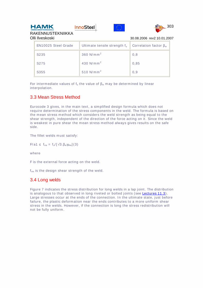
EN10025 Steel Grade Ultimate tensile strength fu Correlation factor βw
S235
S275
S355
360 N/mm2
430 N/mm2
510 N/mm2
0,8
0,85
0,9
For intermediate values of fu the value of βw may be determined by linear interpolation.
3.3 Mean Stress Method
Eurocode 3 gives, in the main text, a simplified design formula which does not require determination of the stress components in the weld. The formula is based on the mean stress method which considers the weld strength as being equal to the shear strength, independent of the direction of the force acting on it. Since the weld is weakest in pure shear the mean stress method always gives results on the safe side.
The fillet welds must satisfy:
F/a1 ≤ fvw = fu/[√3.βwγMw](3)
where
F is the external force acting on the weld.
fvw is the design shear strength of the weld.
3.4 Long welds
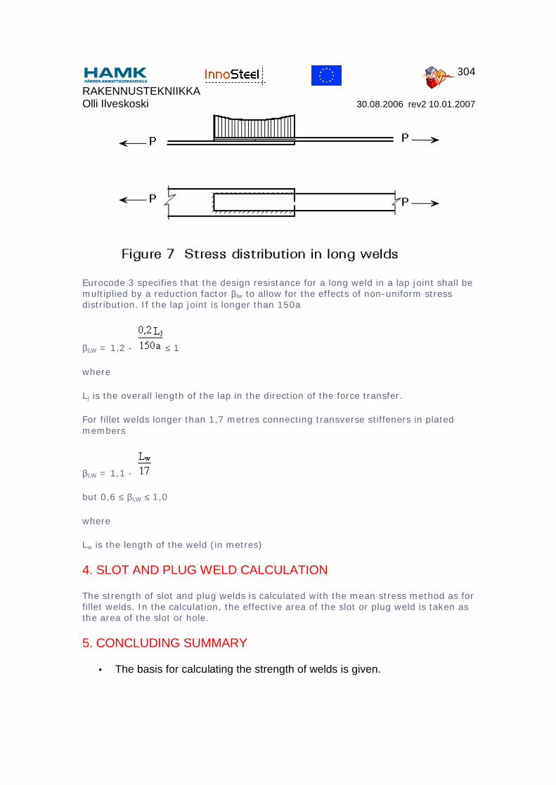
Figure 7 indicates the stress distribution for long welds in a lap joint. The distribution is analogous to that observed in long riveted or bolted joints (see Lectures 11.3). Large stresses occur at the ends of the connection. In the ultimate state, just before failure, the plastic deformation near the ends contributes to a more uniform shear stress in the welds. However, if the connection is long the stress redistribution will not be fully uniform.
RAKENNUSTEKNIIKKA Olli Ilveskoski 30.08.2006 rev2 10.01.2007
304
Eurocode 3 specifies that the design resistance for a long weld in a lap joint shall be multiplied by a reduction factor βlw to allow for the effects of non-uniform stress distribution. If the lap joint is longer than 150a
βLW = 1,2 - ≤ 1
where
Lj is the overall length of the lap in the direction of the force transfer.
For fillet welds longer than 1,7 metres connecting transverse stiffeners in plated members
βLW = 1,1 -
but 0,6 ≤ βLW ≤ 1,0
where
Lw is the length of the weld (in metres)
4. SLOT AND PLUG WELD CALCULATION
The strength of slot and plug welds is calculated with the mean stress method as for fillet welds. In the calculation, the effective area of the slot or plug weld is taken as the area of the slot or hole.
5. CONCLUDING SUMMARY
• The basis for calculating the strength of welds is given.
RAKENNUSTEKNIIKKA Olli Ilveskoski 30.08.2006 rev2 10.01.2007
305
• It is noted that residual stresses and stress concentrations are neglected since there is a considerable stress redistribution in the ultimate state. For long welds in lap joints, however, a non-uniform stress distribution is taken into consideration.
• Generally, butt welds require no calculations for design. Calculation is only required in the case of partial penetration welds.
• Following Eurocode 3, a mean stress method as well as an alternative method (Annex M) are given for fillet weld design. The mean stress method does not require calculation of individual stress comments in the welds but generally leads to more conservative results.
6. REFERENCES
[1] Eurocode 3: "Design of steel structures": ENV 1993-1-1: Part 1: General rules and rules for buildings, CEN, 1992.
[2] Bresler, B., Lim, T. Y., Scalzi, J. B., Design of steel structures, 2nd Edition, 1968.
6. ADDITIONAL READING
1. Owens, G. W. and Cheal, B. D., Structural Steelwork Connections, 1st Edition, 1989.
2. Bludgett, O.W., 'Design of welded structures', James F Lincoln Arc Welding Foundation, Cleveland, Ohio, USA, 1972.
Informative and well illustrated reference manual covering all aspects of welded design and construction.
Previous | Next | Contents
RAKENNUSTEKNIIKKA Olli Ilveskoski 30.08.2006 rev2 10.01.2007
306
Lecture 11.3.1 : Connections with Non-Preloaded Bolts
Top
1. INTRODUCTION
2. PRINCIPLE OF LOAD TRANSMISSION
3. DIMENSIONS OF THE BOLTS
4. BOLT GRADES
5. DIAMETER OF THE HOLES
6. NOMINAL AND STRESS SECTIONS OF
7. SHEAR RESISTANCE
7.1 Normal Joints
7.2 Long Joints
8. BEARING RESISTANCE
9. TENSION RESISTANCE
10. BOLTS SUBJECT TO SHEAR AND TENSION
11. SPACING REQUIREMENTS
11.1 Basis
11.2 Connections of plates
11.2.1 Minimum end distance
11.2.2 Minimum edge distance
11.3.3 Maximum end and edge distances
11.2.4 Minimum spacing
11.2.5 Maximum spacing in compression members
11.2.6 Maximum spacing in tension members
11.3 Angles Connected by One Leg

RAKENNUSTEKNIIKKA Olli Ilveskoski 30.08.2006 rev2 10.01.2007
307
11. CONCLUDING SUMMARY
12. REFERENCES
RAKENNUSTEKNIIKKA Olli Ilveskoski 30.08.2006 rev2 10.01.2007
308
Previous | Next | Contents
ESDEP WG 11
CONNECTION DESIGN: STATIC LOADING
Lecture 11.3.1: Connections with Non-Preloaded Bolts
OBJECTIVE
To present the basic ideas of the design of connections using ordinary (non-preloaded) bolts.
PREREQUISITES
Lecture 1B.1: Process of Design
Lecture 2.4: Steel Grades and Qualities
Lectures 3.2: Erection
Lecture 11.1.2: Introduction to Connection Design
RELATED LECTURES
Lectures 11.3: Other lectures on the Design of Bolted Connections
Lectures 11.4: Analysis of Connections
Lecture 12.6: Fatigue Behaviour of Bolted Connections
SUMMARY
This lecture presents the geometrical and mechanical properties of ordinary bolts and describes their behaviour in shear, tension or combined shear and tension.
The effects of the position of the bolts in a connection and of their dimensions on the potential failure modes are also discussed.
NOTATION
A Area of the shank - nominal area [mm2]
As Stress area [mm2]
d Nominal diameter of the bolt (shank) [mm]
RAKENNUSTEKNIIKKA Olli Ilveskoski 30.08.2006 rev2 10.01.2007
309
do Nominal diameter of the hole [mm]
ds Diameter of the stress area (As) [mm]
e1 End distance [mm]
e2 Edge distance [mm]
F Applied load [N]
Fv Shear force [N]
Fv,Rd Design shear resistance of a bolt [N]
Ft Tensile force [N]
Ft,Rd Design tension resistance of a bolt [N]
Fb.Rd Design bearing resistance [N]
fu Ultimate tensile strength of a steel element [MPa]
fu,b Nominal ultimate stress of the bolt material [MPa]
fy,b Nominal yield stress of the bolt material [MPa]
p1, p2 Pitches [mm]
t Plate thickness [mm]
γMb Partial safety factor for the bolt [-]
1. INTRODUCTION
The resistance of a bolted connection is normally determined on the basis of the resistance of the individual fasteners and the connected parts.
Linear-elastic analysis is most frequently used in the design of the connection. Alternatively non-linear analysis of the connection may be employed, provided that it takes account of the load-deformation characteristics of all the components of the connection. Further information about analysis of connections is given in Lectures 11.4.
The present lecture concentrates on the most common type of bolt, the non-preloaded bolt, often called an "ordinary bolt". It is popular because of its low cost both to buy and to install. Connections made with this type of bolt are often referred to as "bearing-type" so as to distinguish them from the slip resistant connections that employ preloaded bolts.
RAKENNUSTEKNIIKKA Olli Ilveskoski 30.08.2006 rev2 10.01.2007
310
Where a joint loaded in shear is subject to impact or significant vibration, welding or bolts with locking devices, preloaded bolts or other types of bolt which effectively prevent movement should be used.
Where slip is not acceptable in a joint subject to reversal of shear load (or for any other reason), preloaded bolts in a slip-resistant connection, fitted bolts, injection bolts or other bolts with the same effect should be used, see Lectures 11.3.2 and 11.3.3.
For wind and/or stability bracing, bolts in bearing-type connections may normally be used.
2. PRINCIPLE OF LOAD TRANSMISSION
In structural connections, bolts are used to transfer loads from one plate to another. The following figures give some examples where bolts are used, loaded by:
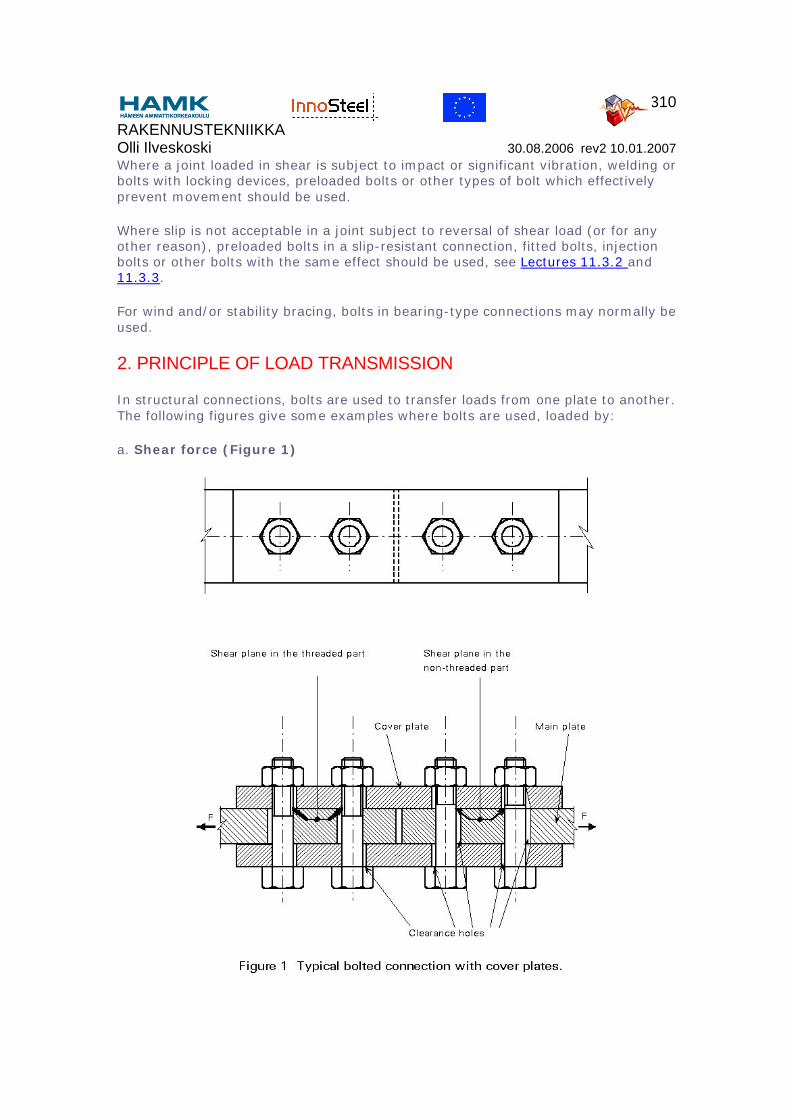
a. Shear force (Figure 1)
RAKENNUSTEKNIIKKA Olli Ilveskoski 30.08.2006 rev2 10.01.2007
311
The load is transmitted into and out of the bolts by bearing on the connected plates. The forces in the bolts are transmitted by transverse shear.
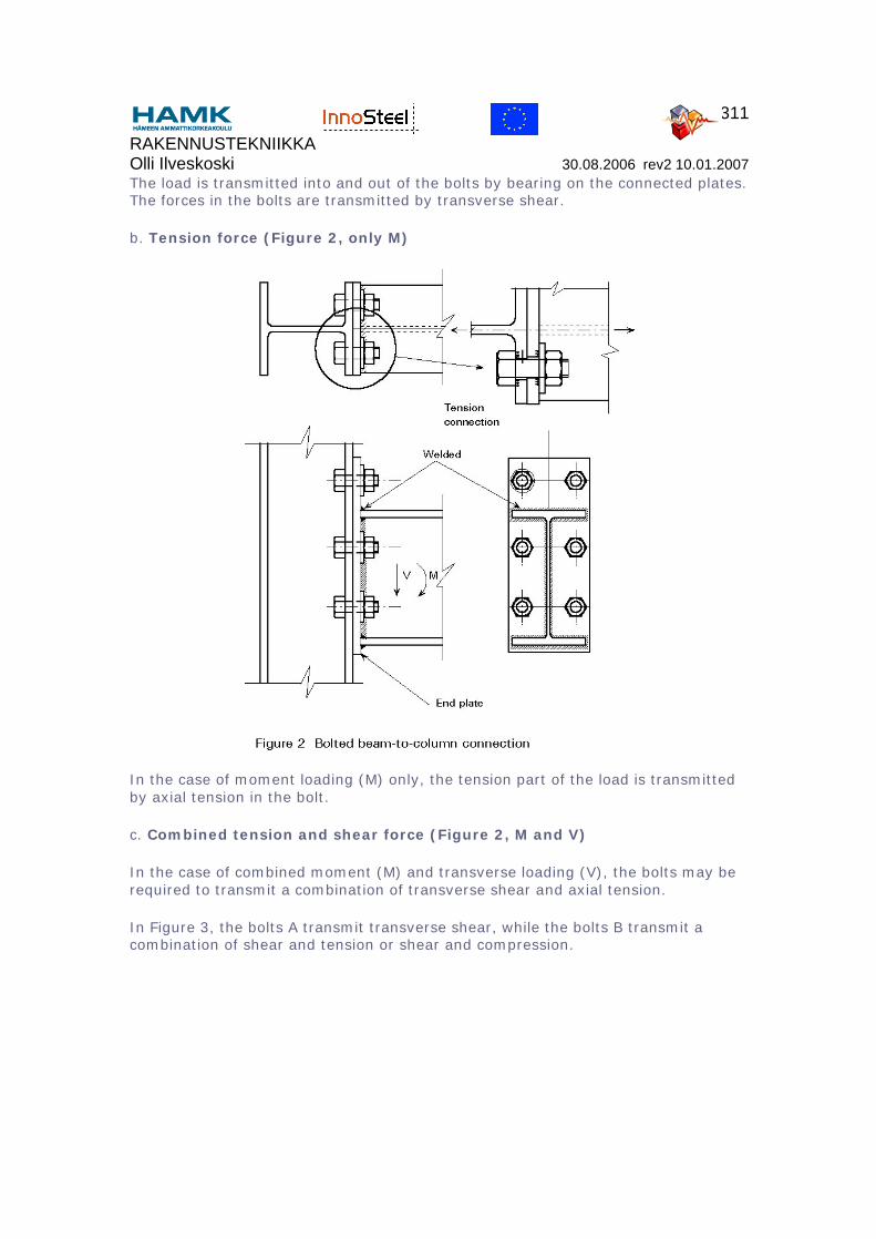
b. Tension force (Figure 2, only M)
In the case of moment loading (M) only, the tension part of the load is transmitted by axial tension in the bolt.
c. Combined tension and shear force (Figure 2, M and V)
In the case of combined moment (M) and transverse loading (V), the bolts may be required to transmit a combination of transverse shear and axial tension.
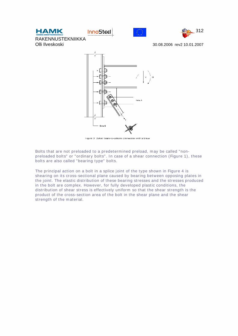
In Figure 3, the bolts A transmit transverse shear, while the bolts B transmit a combination of shear and tension or shear and compression.
RAKENNUSTEKNIIKKA Olli Ilveskoski 30.08.2006 rev2 10.01.2007
312
Bolts that are not preloaded to a predetermined preload, may be called "non-preloaded bolts" or "ordinary bolts". In case of a shear connection (Figure 1), these bolts are also called "bearing type" bolts.
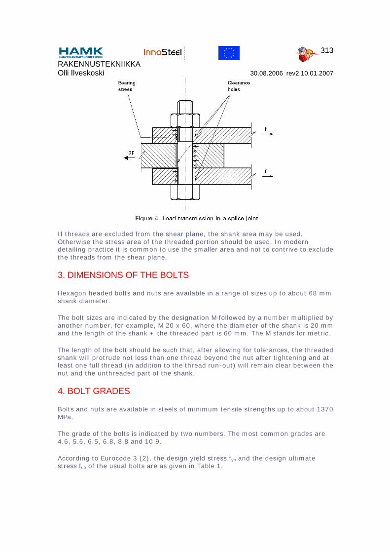
The principal action on a bolt in a splice joint of the type shown in Figure 4 is shearing on its cross-sectional plane caused by bearing between opposing plates in the joint. The elastic distribution of these bearing stresses and the stresses produced in the bolt are complex. However, for fully developed plastic conditions, the distribution of shear stress is effectively uniform so that the shear strength is the product of the cross-section area of the bolt in the shear plane and the shear strength of the material.
RAKENNUSTEKNIIKKA Olli Ilveskoski 30.08.2006 rev2 10.01.2007
313
If threads are excluded from the shear plane, the shank area may be used. Otherwise the stress area of the threaded portion should be used. In modern detailing practice it is common to use the smaller area and not to contrive to exclude the threads from the shear plane.
3. DIMENSIONS OF THE BOLTS
Hexagon headed bolts and nuts are available in a range of sizes up to about 68 mm shank diameter.
The bolt sizes are indicated by the designation M followed by a number multiplied by another number, for example, M 20 x 60, where the diameter of the shank is 20 mm and the length of the shank + the threaded part is 60 mm. The M stands for metric.
The length of the bolt should be such that, after allowing for tolerances, the threaded shank will protrude not less than one thread beyond the nut after tightening and at least one full thread (in addition to the thread run-out) will remain clear between the nut and the unthreaded part of the shank.
4. BOLT GRADES
Bolts and nuts are available in steels of minimum tensile strengths up to about 1370 MPa.
The grade of the bolts is indicated by two numbers. The most common grades are 4.6, 5.6, 6.5, 6.8, 8.8 and 10.9.
According to Eurocode 3 (2), the design yield stress fyb and the design ultimate stress fub of the usual bolts are as given in Table 1.

RAKENNUSTEKNIIKKA Olli Ilveskoski 30.08.2006 rev2 10.01.2007
314
Table 1: Mechanical properties of bolts
Grade 4.6 5.6 6.5 6.8 8.8 10.9
fyb (MPa)
fub (MPa)
240
400
300
500
300
600
480
600
640
800
900
1000
The design yield stress fyb can be derived from the grade by multiplying the first number by the second number times 10. The design ultimate stress fub is the first number times 100 (stresses in MPa).
Bolts of grade 8.8 are used most frequently.
5. DIAMETER OF THE HOLES
Because of the tolerances in the positioning of holes and the tolerances of the bolt diameter (d) and the hole diameter (db), a clearance is necessary (Figure 4).
For bearing-type connections, this clearance may cause slip of the plates when they are loaded.
In the case of alternating loading, this movement may occur at each loading reversal. Normally, such movement is not permitted.
Except for fitted bolts or where low-clearance or oversize holes are specified, the nominal clearance in standard holes shall be:
• 1mm for M12 and M14 bolts • 2mm for M16 to M24 bolts • 3mm for M27 and larger bolts.
Holes with smaller clearances than standard holes may be specified.
Holes with 2mm nominal clearance may also be specified for M12 and M14 bolts, provided that the design meets the following requirements:
• for bolts of strength grade 4.8, 5.8, 6.8 or 10.9, the design shear resistance Fv,Rd is taken as 0,85 times the value given in formulae (3) to (5).
• the design shear resistance Fv,Rd (reduced as above if applicable) is not less than the design bearing resistance Fb,Rd.
Holes will be formed by drilling or punching. Punching holes in steelwork is much faster than drilling but some cracking may appear in the material and therefore, in some cases, holes will not be punched full size but must be punched 2mm diameter less than full size and then reamed. New punching machines which operate at high
RAKENNUSTEKNIIKKA Olli Ilveskoski 30.08.2006 rev2 10.01.2007
315
speeds induce less distortion in the material, and it is expected that more punching will be allowed in the future.
If there is no specification, punching is allowed for material up to 25mm in thickness provided that the hole diameter is not less than the thickness of the material.
Burrs should be removed from holes before assembly except that, where holes are drilled in one operation through parts clamped together which would not otherwise be separated after drilling, they need to be separated to remove the burrs.
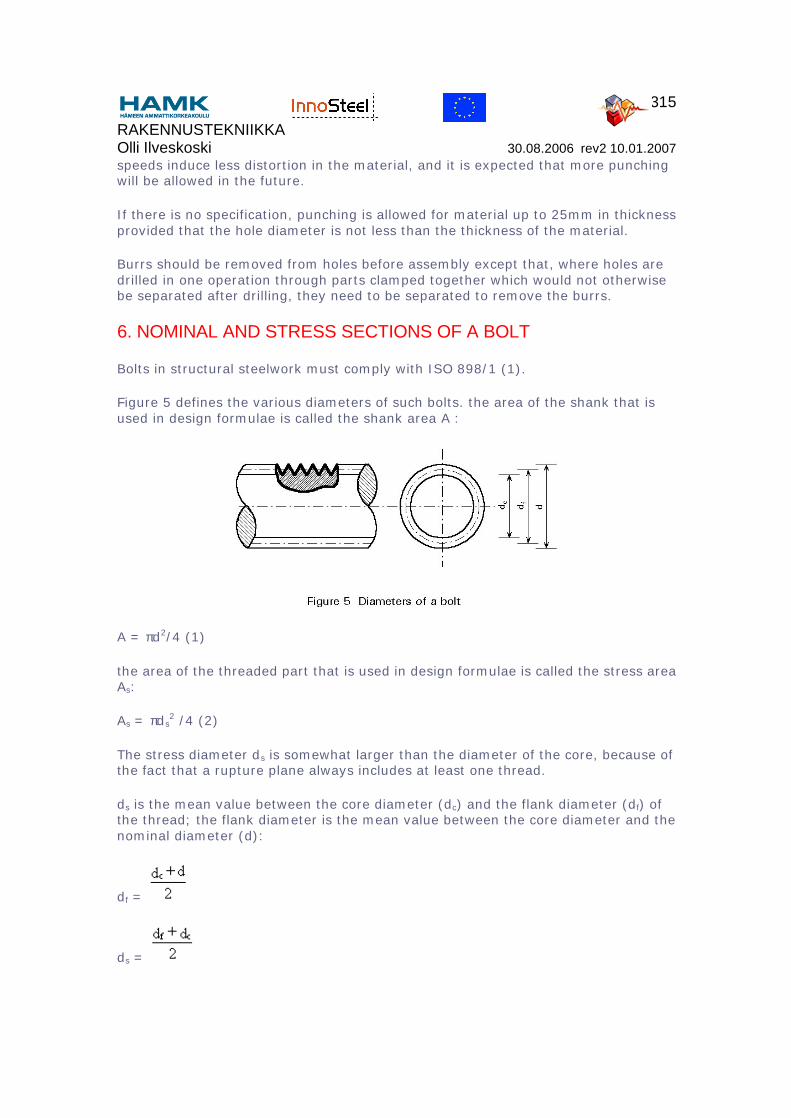
6. NOMINAL AND STRESS SECTIONS OF A BOLT
Bolts in structural steelwork must comply with ISO 898/1 (1).
Figure 5 defines the various diameters of such bolts. the area of the shank that is used in design formulae is called the shank area A :
A = πd2/4 (1)
the area of the threaded part that is used in design formulae is called the stress area As:
As = πds2 /4 (2)
The stress diameter ds is somewhat larger than the diameter of the core, because of the fact that a rupture plane always includes at least one thread.
ds is the mean value between the core diameter (dc) and the flank diameter (df) of the thread; the flank diameter is the mean value between the core diameter and the nominal diameter (d):
df =
ds =
RAKENNUSTEKNIIKKA Olli Ilveskoski 30.08.2006 rev2 10.01.2007
316
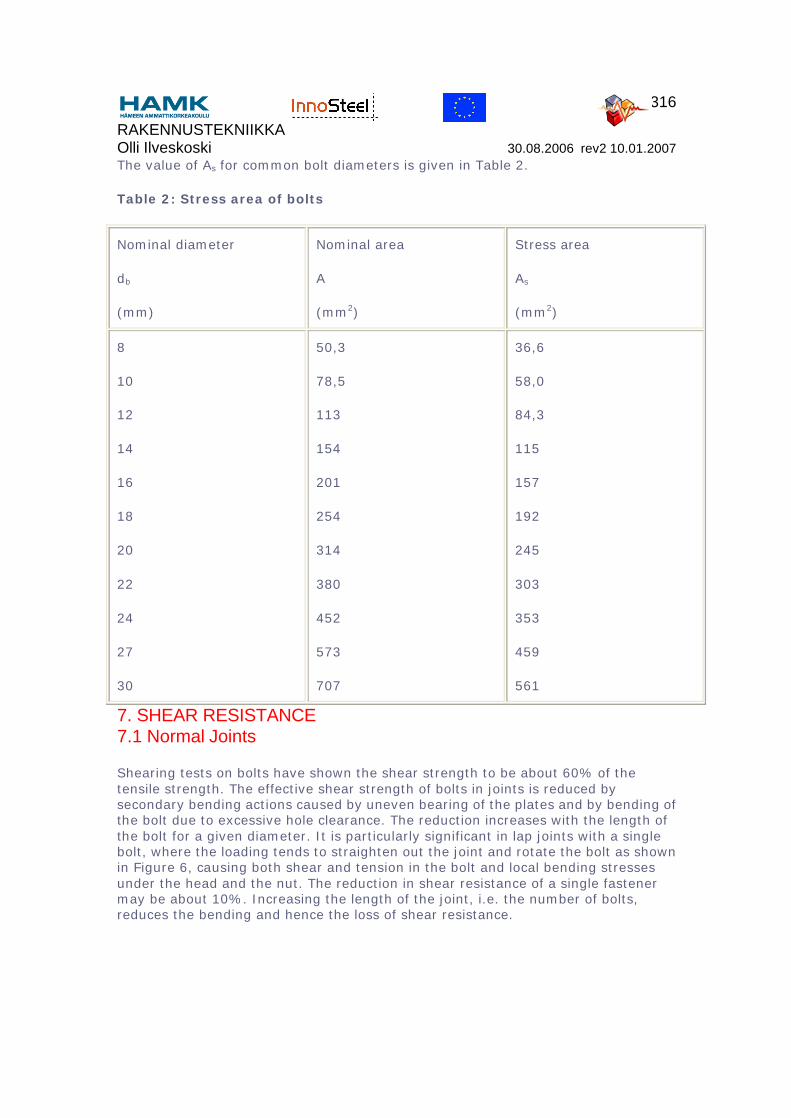
The value of As for common bolt diameters is given in Table 2.
Table 2: Stress area of bolts
Nominal diameter
db
(mm)
Nominal area
A
(mm2)
Stress area
As
(mm2)
8
10
12
14
16
18
20
22
24
27
30
50,3
78,5
113
154
201
254
314
380
452
573
707
36,6
58,0
84,3
115
157
192
245
303
353
459
561
7. SHEAR RESISTANCE7.1 Normal Joints
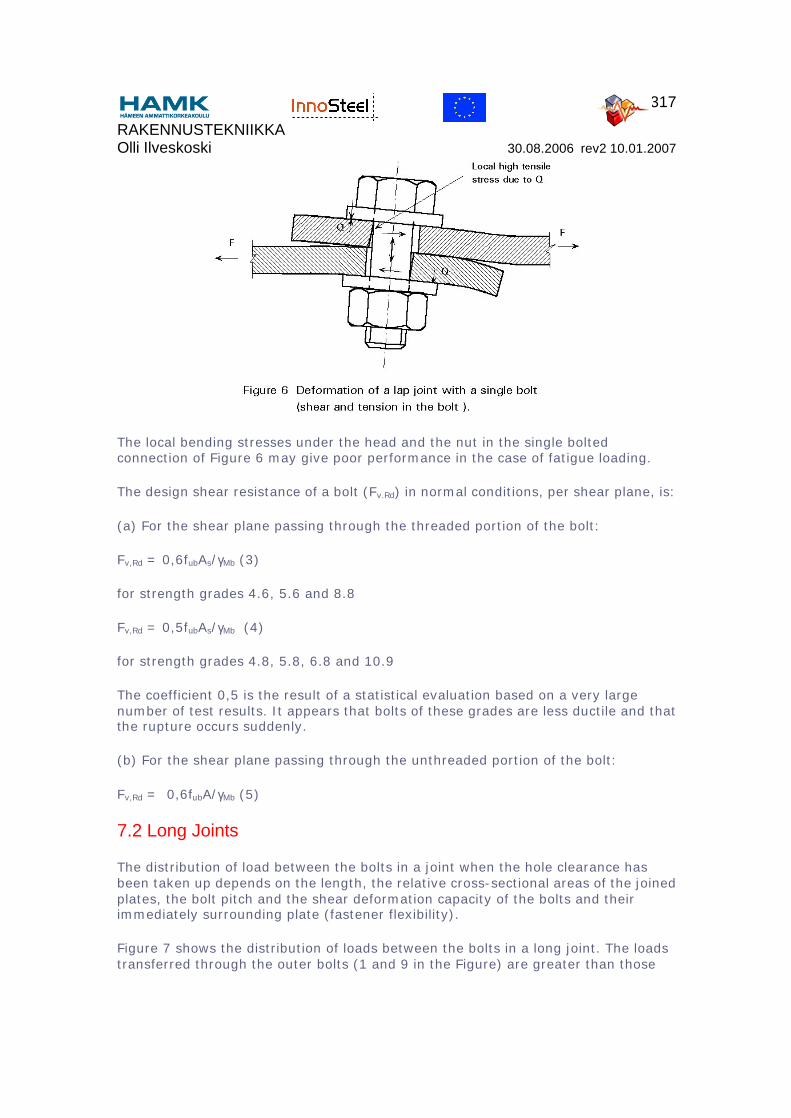
Shearing tests on bolts have shown the shear strength to be about 60% of the tensile strength. The effective shear strength of bolts in joints is reduced by secondary bending actions caused by uneven bearing of the plates and by bending of the bolt due to excessive hole clearance. The reduction increases with the length of the bolt for a given diameter. It is particularly significant in lap joints with a single bolt, where the loading tends to straighten out the joint and rotate the bolt as shown in Figure 6, causing both shear and tension in the bolt and local bending stresses under the head and the nut. The reduction in shear resistance of a single fastener may be about 10%. Increasing the length of the joint, i.e. the number of bolts, reduces the bending and hence the loss of shear resistance.
RAKENNUSTEKNIIKKA Olli Ilveskoski 30.08.2006 rev2 10.01.2007
317
The local bending stresses under the head and the nut in the single bolted connection of Figure 6 may give poor performance in the case of fatigue loading.
The design shear resistance of a bolt (Fv.Rd) in normal conditions, per shear plane, is:
(a) For the shear plane passing through the threaded portion of the bolt:
Fv,Rd = 0,6fubAs/γMb (3)
for strength grades 4.6, 5.6 and 8.8
Fv,Rd = 0,5fubAs/γMb (4)
for strength grades 4.8, 5.8, 6.8 and 10.9
The coefficient 0,5 is the result of a statistical evaluation based on a very large number of test results. It appears that bolts of these grades are less ductile and that the rupture occurs suddenly.
(b) For the shear plane passing through the unthreaded portion of the bolt:
Fv,Rd = 0,6fubA/γMb (5)
7.2 Long Joints
The distribution of load between the bolts in a joint when the hole clearance has been taken up depends on the length, the relative cross-sectional areas of the joined plates, the bolt pitch and the shear deformation capacity of the bolts and their immediately surrounding plate (fastener flexibility).
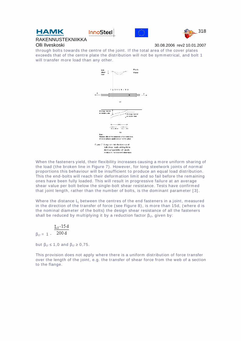
Figure 7 shows the distribution of loads between the bolts in a long joint. The loads transferred through the outer bolts (1 and 9 in the Figure) are greater than those
RAKENNUSTEKNIIKKA Olli Ilveskoski 30.08.2006 rev2 10.01.2007
318
through bolts towards the centre of the joint. If the total area of the cover plates exceeds that of the centre plate the distribution will not be symmetrical, and bolt 1 will transfer more load than any other.
When the fasteners yield, their flexibility increases causing a more uniform sharing of the load (the broken line in Figure 7). However, for long steelwork joints of normal proportions this behaviour will be insufficient to produce an equal load distribution. This the end-bolts will reach their deformation limit and so fail before the remaining ones have been fully loaded. This will result in progressive failure at an average shear value per bolt below the single-bolt shear resistance. Tests have confirmed that joint length, rather than the number of bolts, is the dominant parameter [3].
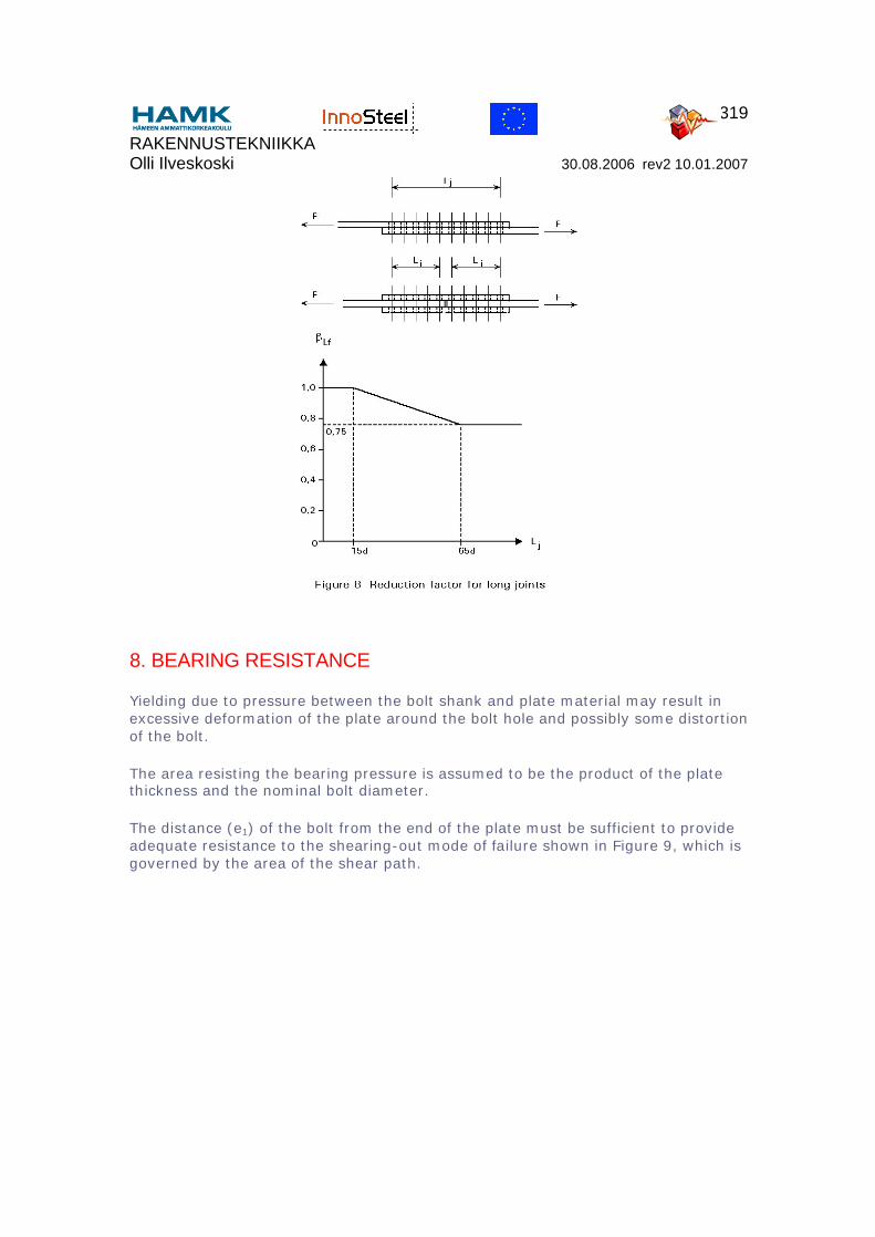
Where the distance Lj between the centres of the end fasteners in a joint, measured in the direction of the transfer of force (see Figure 8), is more than 15d, (where d is the nominal diameter of the bolts) the design shear resistance of all the fasteners shall be reduced by multiplying it by a reduction factor βLf, given by:
βLf = 1 -
but βLf ≤ 1,0 and βLf ≥ 0,75.
This provision does not apply where there is a uniform distribution of force transfer over the length of the joint, e.g. the transfer of shear force from the web of a section to the flange.
RAKENNUSTEKNIIKKA Olli Ilveskoski 30.08.2006 rev2 10.01.2007
319
8. BEARING RESISTANCE
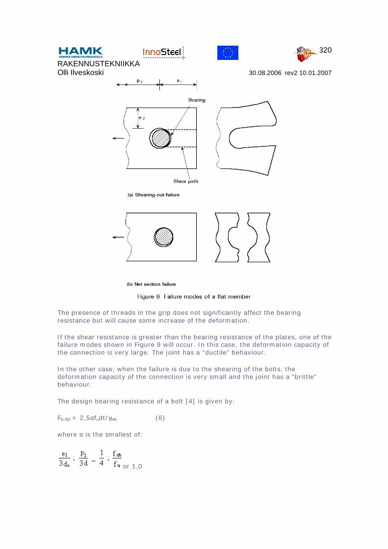
Yielding due to pressure between the bolt shank and plate material may result in excessive deformation of the plate around the bolt hole and possibly some distortion of the bolt.
The area resisting the bearing pressure is assumed to be the product of the plate thickness and the nominal bolt diameter.
The distance (e1) of the bolt from the end of the plate must be sufficient to provide adequate resistance to the shearing-out mode of failure shown in Figure 9, which is governed by the area of the shear path.
RAKENNUSTEKNIIKKA Olli Ilveskoski 30.08.2006 rev2 10.01.2007
320
The presence of threads in the grip does not significantly affect the bearing resistance but will cause some increase of the deformation.
If the shear resistance is greater than the bearing resistance of the plates, one of the failure modes shown in Figure 9 will occur. In this case, the deformation capacity of the connection is very large. The joint has a "ductile" behaviour.
In the other case, when the failure is due to the shearing of the bolts, the deformation capacity of the connection is very small and the joint has a "brittle" behaviour.
The design bearing resistance of a bolt [4] is given by:
Fb.Rd = 2,5αfudt/γMb (6)
where α is the smallest of:
or 1,0
RAKENNUSTEKNIIKKA Olli Ilveskoski 30.08.2006 rev2 10.01.2007
321
This reduction coefficient α is necessary, because when the end distance is short, the capacity of deformation is small.
If the net section of the member is small, net section rupture may govern the failure load of the connection (Figure 9).
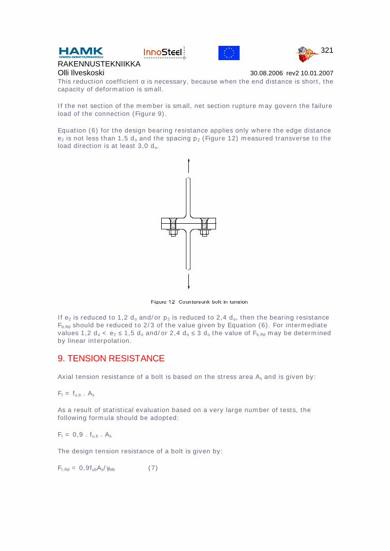
Equation (6) for the design bearing resistance applies only where the edge distance e2 is not less than 1,5 do and the spacing p2 (Figure 12) measured transverse to the load direction is at least 3,0 do.
If e2 is reduced to 1,2 do and/or p2 is reduced to 2,4 do, then the bearing resistance Fb.Rd should be reduced to 2/3 of the value given by Equation (6). For intermediate values 1,2 do < e2 ≤ 1,5 do and/or 2,4 do ≤ 3 do the value of Fb.Rd may be determined by linear interpolation.
9. TENSION RESISTANCE
Axial tension resistance of a bolt is based on the stress area As and is given by:
Ft = fu,b . As
As a result of statistical evaluation based on a very large number of tests, the following formula should be adopted:
Ft = 0,9 . fu,b . As
The design tension resistance of a bolt is given by:
Ft.Rd = 0,9fubAs/γMb (7)
RAKENNUSTEKNIIKKA Olli Ilveskoski 30.08.2006 rev2 10.01.2007
322
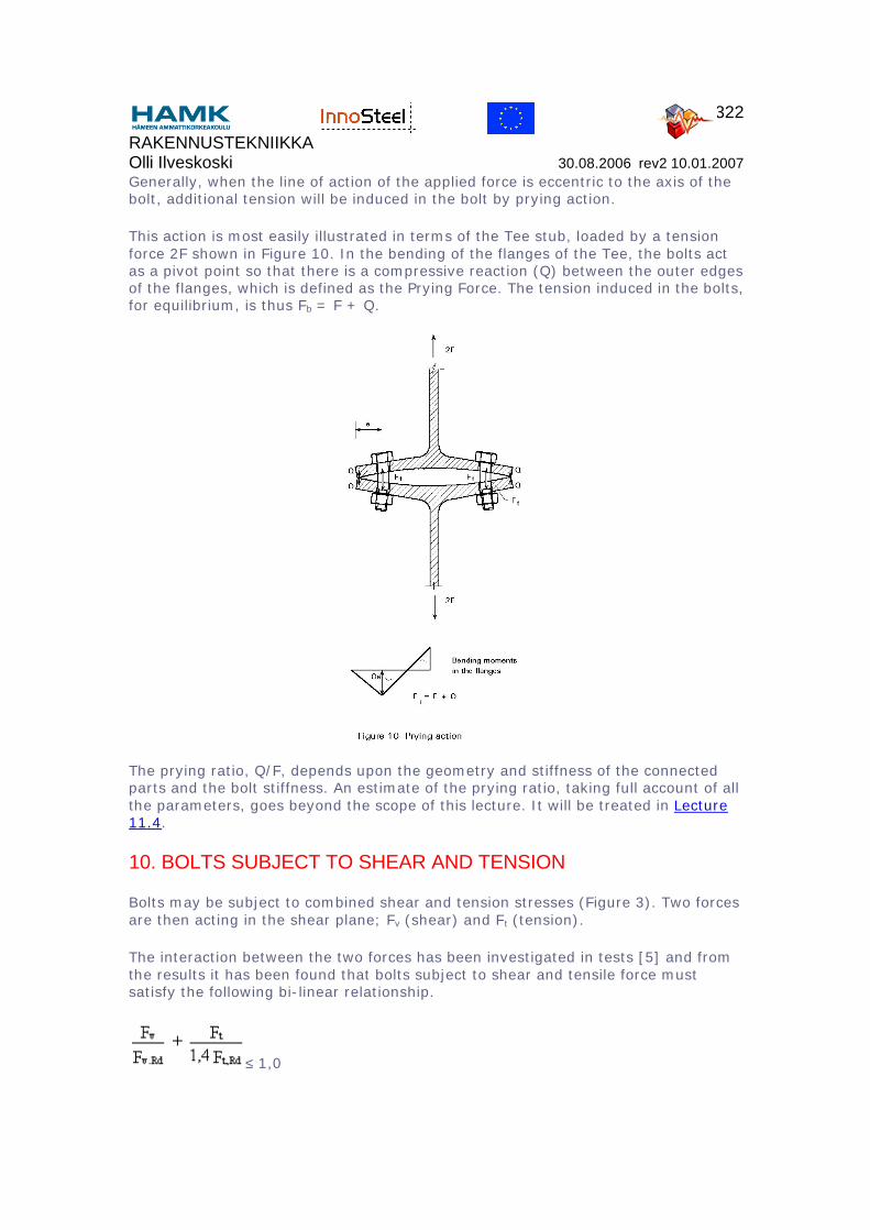
Generally, when the line of action of the applied force is eccentric to the axis of the bolt, additional tension will be induced in the bolt by prying action.
This action is most easily illustrated in terms of the Tee stub, loaded by a tension force 2F shown in Figure 10. In the bending of the flanges of the Tee, the bolts act as a pivot point so that there is a compressive reaction (Q) between the outer edges of the flanges, which is defined as the Prying Force. The tension induced in the bolts, for equilibrium, is thus Fb = F + Q.
The prying ratio, Q/F, depends upon the geometry and stiffness of the connected parts and the bolt stiffness. An estimate of the prying ratio, taking full account of all the parameters, goes beyond the scope of this lecture. It will be treated in Lecture 11.4.
10. BOLTS SUBJECT TO SHEAR AND TENSION
Bolts may be subject to combined shear and tension stresses (Figure 3). Two forces are then acting in the shear plane; Fv (shear) and Ft (tension).
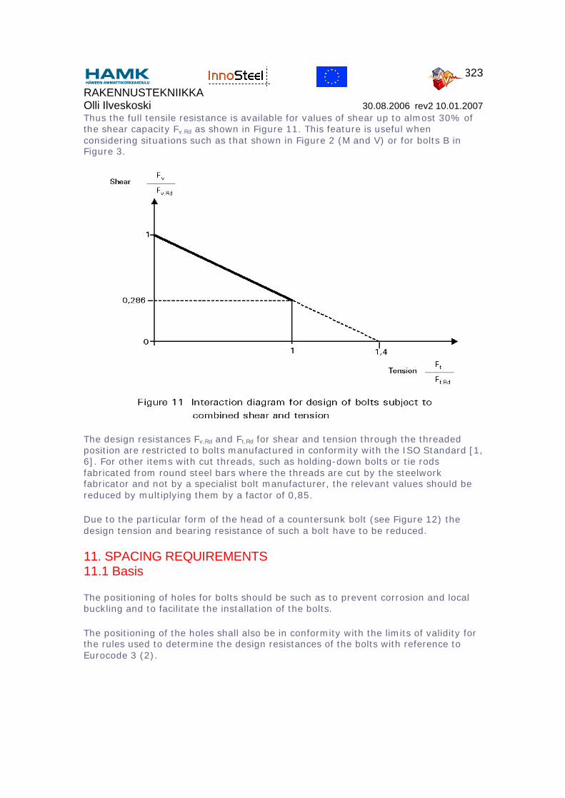
The interaction between the two forces has been investigated in tests [5] and from the results it has been found that bolts subject to shear and tensile force must satisfy the following bi-linear relationship.
≤ 1,0
RAKENNUSTEKNIIKKA Olli Ilveskoski 30.08.2006 rev2 10.01.2007
323
Thus the full tensile resistance is available for values of shear up to almost 30% of the shear capacity Fv.Rd as shown in Figure 11. This feature is useful when considering situations such as that shown in Figure 2 (M and V) or for bolts B in Figure 3.
The design resistances Fv,Rd and Ft,Rd for shear and tension through the threaded position are restricted to bolts manufactured in conformity with the ISO Standard [1, 6]. For other items with cut threads, such as holding-down bolts or tie rods fabricated from round steel bars where the threads are cut by the steelwork fabricator and not by a specialist bolt manufacturer, the relevant values should be reduced by multiplying them by a factor of 0,85.
Due to the particular form of the head of a countersunk bolt (see Figure 12) the design tension and bearing resistance of such a bolt have to be reduced.
11. SPACING REQUIREMENTS11.1 Basis
The positioning of holes for bolts should be such as to prevent corrosion and local buckling and to facilitate the installation of the bolts.
The positioning of the holes shall also be in conformity with the limits of validity for the rules used to determine the design resistances of the bolts with reference to Eurocode 3 (2).
RAKENNUSTEKNIIKKA Olli Ilveskoski 30.08.2006 rev2 10.01.2007
324
11.2 Connections of plates
11.2.1 Minimum end distance
The end distance e1 from the centre of a fastener hole to the adjacent end of any part, measured in the direction of load transfer (see Figure 12a), should not be less than 1,2 do, where do is the hole diameter.
The end distance should be increased if necessary to provide adequate bearing resistance, see Section 8.
11.2.2 Minimum edge distance
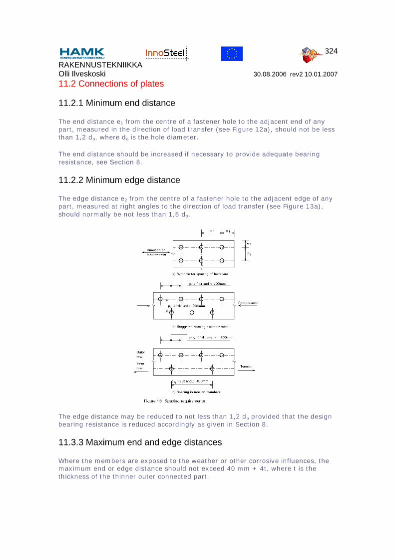
The edge distance e2 from the centre of a fastener hole to the adjacent edge of any part, measured at right angles to the direction of load transfer (see Figure 13a), should normally be not less than 1,5 do.
The edge distance may be reduced to not less than 1,2 do provided that the design bearing resistance is reduced accordingly as given in Section 8.
11.3.3 Maximum end and edge distances
Where the members are exposed to the weather or other corrosive influences, the maximum end or edge distance should not exceed 40 mm + 4t, where t is the thickness of the thinner outer connected part.
RAKENNUSTEKNIIKKA Olli Ilveskoski 30.08.2006 rev2 10.01.2007
325
In other cases the end or edge distance should not exceed 12t or 150 mm, whichever is the larger.
The edge distance should also not exceed the maximum to satisfy local buckling requirements for an outstanding element. This requirement does not apply to fasteners interconnecting the components of back-to-back tension members. The end distance is not affected by this requirement.
11.2.4 Minimum spacing
The spacing p1 between centres of fasteners in the direction of load (see Figure 13b) should not be less than 2,2 do. This spacing should be increased if necessary to provide adequate bearing resistance, see Section 8.
The spacing p2 between rows of fasteners, measured perpendicular to the direction of load, (see Figure 13b), should normally be not less than 3,0 do. This spacing may be reduced to 2,4 do if the design bearing resistance is reduced accordingly, see Section 8.
11.2.5 Maximum spacing in compression members
The spacing p1 of the fasteners in each row and the spacing p2 between rows of fasteners, should not exceed the lesser of 14t or 200 mm. Adjacent rows of fasteners may be symmetrically staggered, see Figure 13b.
The centre-to-centre spacing of fasteners should also not exceed the maximum to satisfy local buckling requirements for an internal element.
11.2.6 Maximum spacing in tension members
In tension members the centre-to-centre spacing p1,i of fasteners in inner rows may be twice that given in Section 10.2.5 for compression in members, provided that the spacing p1,o in the outer row along each edge does not exceed that given in Section 10.2.5, see Figure 13c.
Both of these values may be multiplied by 1,5 in members not exposed to the weather or other corrosive influences.
11.3 Angles Connected by One Leg
In the case of unsymmetrical or unsymmetrically connected members such as angles connected by one leg, the eccentricity of fasteners in end connections and the effects of the spacing and edge determine the design resistance.
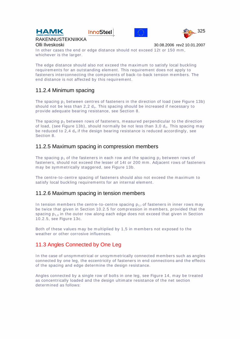
Angles connected by a single row of bolts in one leg, see Figure 14, may be treated as concentrically loaded and the design ultimate resistance of the net section determined as follows:
RAKENNUSTEKNIIKKA Olli Ilveskoski 30.08.2006 rev2 10.01.2007
326
with 1 bolt: Nu,Rd = 2,0(e2 - 0,5do)tfu/γM2
with 2 bolts: Nu,Rd = β3Anetfu/γM2
with 3 or more bolts: Nu,Rd = β3Anetfu/γM2
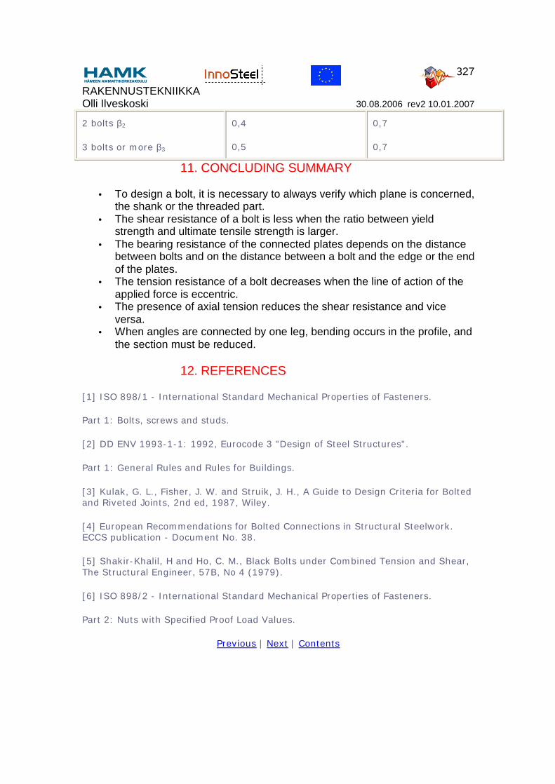
where β2 and β3 are reduction factors dependant on the pitch p1 as given in Table 3. For intermediate values of p1 the value of β may be determined by linear interpolation,
and Anet is the net section area of the angle. For an unequal-leg angle connected by its smaller leg, Anet should be taken as equal to the net section area of an equivalent equal-leg angle of leg size equal to that of the smaller leg.
Table 3 - reduction factors β2 and β3
Pitch p1 ≤ 2,5 do ≥ 5,0 do
RAKENNUSTEKNIIKKA Olli Ilveskoski 30.08.2006 rev2 10.01.2007
327
2 bolts β2
3 bolts or more β3
0,4
0,5
0,7
0,7
11. CONCLUDING SUMMARY
• To design a bolt, it is necessary to always verify which plane is concerned, the shank or the threaded part.
• The shear resistance of a bolt is less when the ratio between yield strength and ultimate tensile strength is larger.
• The bearing resistance of the connected plates depends on the distance between bolts and on the distance between a bolt and the edge or the end of the plates.
• The tension resistance of a bolt decreases when the line of action of the applied force is eccentric.
• The presence of axial tension reduces the shear resistance and vice versa.
• When angles are connected by one leg, bending occurs in the profile, and the section must be reduced.
12. REFERENCES
[1] ISO 898/1 - International Standard Mechanical Properties of Fasteners.
Part 1: Bolts, screws and studs.
[2] DD ENV 1993-1-1: 1992, Eurocode 3 "Design of Steel Structures".
Part 1: General Rules and Rules for Buildings.
[3] Kulak, G. L., Fisher, J. W. and Struik, J. H., A Guide to Design Criteria for Bolted and Riveted Joints, 2nd ed, 1987, Wiley.
[4] European Recommendations for Bolted Connections in Structural Steelwork. ECCS publication - Document No. 38.
[5] Shakir-Khalil, H and Ho, C. M., Black Bolts under Combined Tension and Shear, The Structural Engineer, 57B, No 4 (1979).
[6] ISO 898/2 - International Standard Mechanical Properties of Fasteners.
Part 2: Nuts with Specified Proof Load Values.
Previous | Next | Contents