Embed Size (px)
Citation preview
Conservation of Fueland Energy - Buildingsother than Dwellings
T e chn i c a lGu i d a n c eDocumen t
L
Department of Housing, Planning and Local Government
An Roinn Tithíochta, Pleanála agus Rialtais Áitiúil
Bui ldingRegulat ions
2017

Building Regulations 2017
Technical Guidance Document L -
Buildings other than Dwellings
Conservation of Fuel and Energy
BAILE ÁTHA CLIATH ARNA FHOILSIÚ AG OIFIG AN tSOLÁTHAIR Le ceannach díreach ó FOILSEACHÁIN RIALTAIS, 52 FAICHE STIABHNA, BAILE ÁTHA CLIATH 2 (Teil: 01 – 6476834 nó 1890 213434; Fax 01 – 6476843) __________ DUBLIN PUBLISHED BY THE STATIONERY OFFICE To be purchased from GOVERNMENT PUBLICATIONS, 52 ST. STEPHEN'S GREEN, DUBLIN 2. (Tel: 01 – 6476834 or 1890 213434; Fax: 01 – 6476843)
_______________________ Price €XXXX ISBN XXXX XXXX XXXX
Printed on recycled paper containing a minimum of 75% post-consumer waste

© Government of Ireland 2017
Contents
1
Page
Introduction 5
Transitional arrangements 5
The Guidance 6
Technical Specifications 6
Materials and Workmanship 6
Interpretation 6
Part L- The Requirement 7
Section 0: General guidance 9
0.1 Application of the Regulations 9
0.1.1 General 9
0.1.2 New Buildings other than Dwellings 10
0.1.3 Existing Buildings other than Dwellings 12
0.2 Technical Risks and Precautions 14
0.2.1 General 14
0.2.2 Fire safety 14
0.2.3 Ventilation 14
0.3 Thermal Conductivity and Thermal Transmittance 14
0.4 Dimensions 16
0.5 Definitions 16
0.6 Application to Buildings of Architectural or Historical Interest 18
Contents Cont’d
2
Section 1: New Buildings other than Dwellings 19
1.1 Limitation of CO2 Emissions 20
1.2 Renewable Energy Technologies 22
1.3 Building Fabric 24
1.3.1 General 24
1.3.2 Fabric Insulation 24
1.3.3 Thermal Bridging 27
1.3.4 Building Envelope Air Permeability 28
1.3.5 Limiting the effects of solar gain in summer 29
1.3.6 Limiting Overheating 30
1.4 Building Services 32
1.4.1 Heat Generator Efficiency 32
1.4.2 Controls for Space Heating and Hot Water Supply Systems 33
1.4.3 Air Conditioning and Mechanical Ventilation (ACMV) 37
1.4.4 Air Conditioning and Mechanical Ventilation Controls 40
1.4.5 Insulation of Storage Vessels, Pipes and ducts 42
1.4.6 Artificial Lighting 42
1.5 Construction quality and commissioning of services 45
1.5.1 General 45
1.5.2 Insulation continuity and Air Permeability 45
1.5.3 Thermal Bridging 45
1.5.4 Air Permeability Pressure Tests 45
1.5.5. Commissioning Space and Water Heating Systems 46
1.6 User Information 47
1.6.1 General 47
Contents Cont’d
3
Section 2: Existing Buildings other than Dwellings 48
2.1 Building Fabric 48
2.1.1 General 48
2.1.2 Fabric Insulation 49
2.1.3 Thermal Bridging 52
2.1.4 Air Permeability 54
2.2 Building Services 55
2.2.1 General 55
2.2.2 Heating Plant Efficiency 56
2.2.3 Controls for Space Heating and Hot Water Systems 56
2.2.4 Air Conditioning and Mechanical Ventilation 57
2.2.5 Air Conditioning and Mechanical Ventilation (ACMV) Controls 60
2.2.6 Insulation of Storage Vessels, Pipes and Ducts 61
2.2.7 Artificial Lighting 61
2.3 Major Renovation 63
2.4 Construction quality and commissioning of services 64
2.4.1 General 64
2.4.2 Insulation continuity and air permeability 64
2.4.3 Commissioning space and water heating systems 64
2.4.4 Air Leakage Testing of Ductwork 65
2.5 User information 65
2.5.1 General 65
Appendices 66
A Calculation of U-values 67
B Fabric Insulation: Additional Guidance for Common Constructions 79
C Reference Values for calculation of Maximum Permitted Energy Performance Coefficient (MPEPC) and Maximum Permitted Carbon Performance Coefficient (MPCPC) 95
Contents Cont’d
4
D Thermal Bridging 98
E Specific Fan Power Calculation 100
F Lighting 103
G Pipework and Ductwork Insulation 106
Abbreviations 109
Standards and Publications 110
Buildings Regulations 2017 Technical Guidance Document L – Conservation of Fuel and Energy for buildings other than Dwellings
5
Introduction This document has been published by the Minister for the Housing, Planning and Local Government under article 7 of the Building Regulations 1997. It provides guidance in relation to Part L of the Second Schedule to the Regulations as inserted by Building Regulations (Part L Amendment) Regulations (S.I. No. 538 of 2017). The guidance in this document applies to buildings other than dwellings. The 2017 Part L Regulations (and this document) partly transpose the EU Energy Performance of Buildings Directive Recast (EPBD Recast) 2010/31/EU of 19th May 2010. The 2017 amendment to Part L (Conservation of Fuel and Energy) of the Building Regulations and this Technical Guidance Document L, provide for the implementation of requirements of Articles 2,3 4, 6 (part of), 7, 8, 9(3,b) of the EU Energy Performance of Buildings Directive – EPBD (recast) (2010/31/EU of 19 May 2010). These requirements include:
application of a methodology for the calculation of the energy performance of buildings on the basis of a general framework set out in Annex I to the EPBD (recast).
setting of minimum energy performance requirements for buildings and the application of these requirements to new buildings to achieve Nearly Zero Energy Buildings;
ensuring where buildings undergo major renovation that the renovated systems- and components meet minimum thermal performance requirements in so far as this is technically, functionally and economically feasible.
ensuring that when a building element that forms part of the building envelope and has a significant impact on the energy performance of the building envelope, is retrofitted or replaced, the energy performance of the building element meets minimum energy performance requirements in so far as this is technically, functionally and economically feasible.
The guidance in this document also gives due regard to the cost-optimal levels of minimum energy performance requirements submitted in Ireland’s report to the Commission under Article 5 of the EPBD Recast Directive 2010/31/EU of 19th May 2010. The 2017 Part L Regulations (and this document) set energy performance requirements to achieve Nearly Zero Energy Buildings performance as required by Article 4 (1) of the Directive for new buildings The document should be read in conjunction with the Building Regulations 1997-2017 and other documents published under these Regulations. In general, Building Regulations apply to the construction of new buildings and to extensions and material alterations to existing buildings. In addition, certain parts of the Regulations apply to existing buildings where a material change of use or a major renovation takes place. Otherwise, Building Regulations do not apply to buildings constructed prior to 1 June 1992. Transitional Arrangements In general, this document applies to works, or buildings in which a material alteration or change of use or major renovation takes place, where the work, material alteration or the change of use commences or takes place, as the case may be, on or after 1st January 2019. Technical Guidance Document L - Conservation of Fuel and Energy (2008
6
edition) ceases to have effect from 31st December 2018. However, these documents may continue to be used in the case of buildings:
where the work, material alteration or the change of use commences or takes place, as the case may be, on or before 31st December 2018, or
where planning approval or permission for buildings has been applied for on or before 31st December 2018, and substantial work has been completed by 1st January 2020
“Substantial work has been completed” means that the structure of the external walls has been erected. The Guidance The materials, methods of construction, standards and other specifications (including technical specifications) which are referred to in this document are those which are likely to be suitable for the purposes of the Building Regulations (as amended). Where works are carried out in accordance with the guidance in this document, this will, prima facie, indicate compliance with Part L of the Second Schedule to the Building Regulations. However, the adoption of an approach other than that outlined in the guidance is not precluded provided that the relevant requirements of the Regulations are complied with. Those involved in the design and construction of a building may be required by the relevant building control authority to provide such evidence as is necessary to establish that the requirements of the Regulations are being complied with. Technical Specifications Building Regulations are made for specific purposes, e.g. to provide, in relation to buildings, for the health, safety and welfare of persons, access for people with disabilities and the conservation of fuel and energy.
Technical specifications (including harmonised European Standards, European Technical Approvals, National Standards and Agrément Certificates) are relevant to the extent that they relate to these considerations. Any reference to a technical specification is a reference to so much of the specification as is relevant in the context in which it arises. Technical specification may also address other aspects not covered by the Regulations. A reference to a technical specification is to the latest edition (including any amendments, supplements or addenda) current at the date of publication of this Technical Guidance Document. However, if this version of the technical specification is subsequently revised or updated by the issuing body, the new version may be used as a source of guidance provided that it continues to address the relevant requirements of the
Regulations. Materials and Workmanship
Under Part D of the Second Schedule to the Building Regulations, building work to which the regulations apply must be carried out with proper materials and in a workmanlike manner. Guidance in relation to compliance with Part D is contained in Technical Guidance Document D.
Interpretation
In this document, a reference to a section, paragraph, appendix or diagram is, unless otherwise stated, a reference to a section, paragraph, appendix or diagram, as the case may be, of this document. A reference to another Technical Guidance Document is a reference to the latest edition of a document published by the Department of Housing, Planning, Community and Local Government under article 7 of the Building Regulations 1997. Diagrams are used in this document to illustrate particular aspects of construction - they may not show all the details of construction.
Conservation of Fuel and Energy Buildings other than dwellings
7
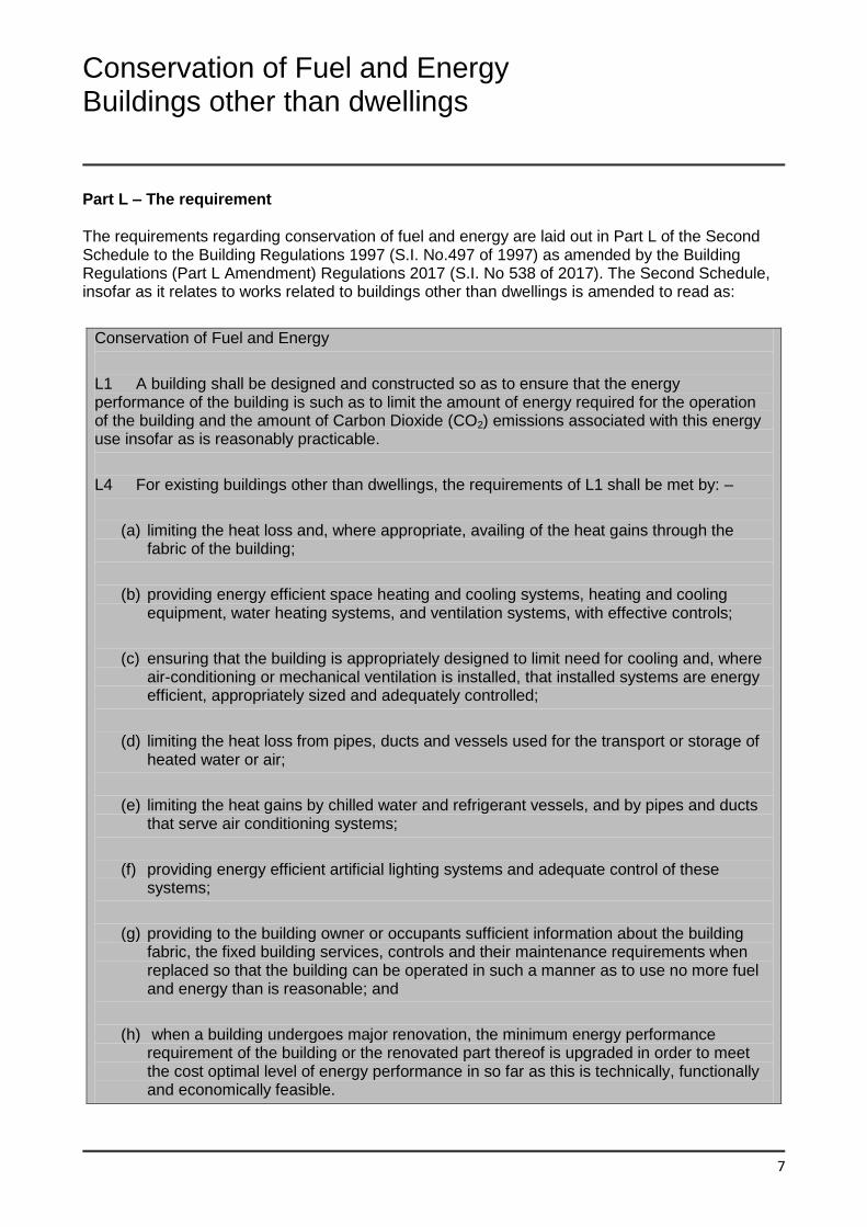
Part L – The requirement The requirements regarding conservation of fuel and energy are laid out in Part L of the Second Schedule to the Building Regulations 1997 (S.I. No.497 of 1997) as amended by the Building Regulations (Part L Amendment) Regulations 2017 (S.I. No 538 of 2017). The Second Schedule, insofar as it relates to works related to buildings other than dwellings is amended to read as:
Conservation of Fuel and Energy
L1 A building shall be designed and constructed so as to ensure that the energy performance of the building is such as to limit the amount of energy required for the operation of the building and the amount of Carbon Dioxide (CO2) emissions associated with this energy use insofar as is reasonably practicable.
L4 For existing buildings other than dwellings, the requirements of L1 shall be met by: –
(a) limiting the heat loss and, where appropriate, availing of the heat gains through the fabric of the building;
(b) providing energy efficient space heating and cooling systems, heating and cooling equipment, water heating systems, and ventilation systems, with effective controls;
(c) ensuring that the building is appropriately designed to limit need for cooling and, where air-conditioning or mechanical ventilation is installed, that installed systems are energy efficient, appropriately sized and adequately controlled;
(d) limiting the heat loss from pipes, ducts and vessels used for the transport or storage of heated water or air;
(e) limiting the heat gains by chilled water and refrigerant vessels, and by pipes and ducts that serve air conditioning systems;
(f) providing energy efficient artificial lighting systems and adequate control of these systems;
(g) providing to the building owner or occupants sufficient information about the building fabric, the fixed building services, controls and their maintenance requirements when replaced so that the building can be operated in such a manner as to use no more fuel and energy than is reasonable; and
(h) when a building undergoes major renovation, the minimum energy performance requirement of the building or the renovated part thereof is upgraded in order to meet the cost optimal level of energy performance in so far as this is technically, functionally and economically feasible.
8
L5 For new buildings other than dwellings, the requirements of L1 shall be met by: –
(a) providing that the energy performance of the building is such as to limit the calculated primary energy consumption and related Carbon Dioxide (CO2) emissions to a Nearly Zero Energy Building level insofar as is reasonably practicable, when both energy consumption and Carbon Dioxide emissions are calculated using the Non-domestic Energy Assessment Procedure (NEAP) published by Sustainable Energy Authority of Ireland;
(b) providing that, the nearly zero or very low amount of energy required is covered to a very significant extent by energy from renewable sources produced on-site or nearby;
(c) limiting the heat loss and, where appropriate, availing of the heat gains through the fabric of the building;
(d) providing and commissioning energy efficient space heating and cooling systems, heating and cooling equipment, water heating systems, and ventilation systems, with effective controls;
(e) ensuring that the building is appropriately designed to limit need for cooling and, where air-conditioning or mechanical ventilation is installed, that installed systems are energy efficient, appropriately sized and adequately controlled;
(f) limiting the heat loss from pipes, ducts and vessels used for the transport or storage of heated water or air;
(g) limiting the heat gains by chilled water and refrigerant vessels, and by pipes and ducts that serve air conditioning systems;
(h) providing energy efficient artificial lighting systems and adequate control of these systems; and
(i) providing to the building owner or occupants sufficient information about the building, the fixed building services, controls and their maintenance requirements so that the building can be operated in such a manner as to use no more fuel and energy than is reasonable.
Section 0 General Guidance
9
0.1 Application of the Regulations
0.1.1 General
0.1.1.1 The aim of Part L of the Second
Schedule to the Building Regulations is to
limit the use of fossil fuel energy and related
CO2 emissions arising from the operation of
buildings, while ensuring that occupants can
achieve adequate levels of lighting and
thermal comfort. Buildings should be
designed and constructed to achieve this aim
as far as is practicable.
0.1.1.2 The guidance in this document
applies to works to Buildings other than
Dwellings only. Guidance for dwellings can
be found in a separate Technical Guidance
Document L-Dwellings.
0.1.1.3 The guidance given in this Technical
Guidance Document is generally applicable
to all works associated with the construction
of buildings other than dwellings.
0.1.1.4 The guidance given in this Technical
Guidance Document applies to buildings
designed to be heated to temperatures
appropriate for human occupancy. Less
demanding standards could represent
reasonable provision in those buildings or
parts of buildings with a low level of heating
or where heating provision is not intended.
Low level of heating is considered to be
where there is an installed heating capacity of
less than 10W/m2 and zones are not
designed to be heated to temperatures
appropriate for human occupancy. This
includes buildings where heating and cooling
systems are not provided, or are provided to
only heat or cool a localized area rather than
the entire enclosed volume of the space
concerned eg. localized radiant heaters at a
workstation in a generally unheated space. A
low level of heating can also be considered to
apply where spaces are heated to a level
substantially less than those normally
provided for human comfort e.g. to protect a
warehouse from condensation or frost. In
these situations all fixed building services
should meet the guidance for heating
systems in section 1.4 or 2.2. Fabric should
have a U value appropriate for the heating
system provided and in no case greater than
0.7 W/(m2K) for opaque fabric. If a part of a
building with low energy demand is
partitioned off e.g. a heated office in an
unheated warehouse then the fabric of the
heated partitioned area should meet the
guidance for fabric from sections 1.3 or 2.1.
Where the occupancy level or level of heating
required when in use cannot be established
at construction stage, the building should be
treated as fully heated and the provisions of
Part L applied accordingly. It should be noted
that the provisions of Part L apply where a
material change of use occurs and such a
change of use may require specific
construction measures to comply with Part L.
These measures may prove more costly than
if carried out at the time of initial construction.
In all cases the energy consumption, Carbon
Dioxide emissions and energy from
renewable sources for new buildings should
be modelled in NEAP.
0.1.1.5 The guidance provided in this
document for space heating, cooling, lighting
and ventilation systems are appropriate for
typical conditioned spaces intended for
human occupancy.
Where a building has specialist processes,
alternative operational procedures or
ventilation requirements other than those

10
required for human occupancy different
performance specifications may be
appropriate.
In the context of this section “specialist
processes” can be taken to include any
activity or operational profile where the
resulting need for heating, hot water,
ventilation or air conditioning is significantly
different to that required for human
occupancy.
The Energy Performance Coefficient (EPC),
Carbon Performance Coefficient (CPC) and
Renewable Energy Ratio (RER) calculations
use the NEAP activities database for
occupancy, heating, cooling, ventilation, air
conditioning, lighting, equipment parameters
and profiles.
The Renewable Energy Ratio calculation
should exclude the heating, ventilation and air
conditioning system demands determined by
specialist process requirements, together with
the plant capacity, or proportion of the plant
capacity, provided to service specialist
processes.
The NEAP methodology sets out the
procedures to reflect specialist processes
when calculating the Energy Performance
Coefficient, Carbon Performance Coefficient
and Renewable Energy Ratio.
0.1.1.6 For shell and core buildings the
specification used for the NEAP calculation
should be compatible with the intended
building end use and servicing strategy. The
renewables required should be installed at an
early stage in the construction process that
ensures that the building will meet the
renewables provision for the whole building
when completed and prior to occupation of
any part of the building. Where practical,
renewable systems should be installed on the
shell and core building with the utility
connections or with the primary heating and
cooling services for the building.
0.1.1.7 Where a shell has a fit out
completed on all or part of the building
through the provision or extension of any of
the fixed services for heating, hot water, air-
conditioning or mechanical ventilation then
the Maximum Permitted Energy Performance
Coefficient (MPEPC), Maximum Permitted
Carbon Performance Coefficient (MPCPC)
and Renewable Energy Ratio (RER) should
be based on the building shell as constructed
and the fixed building services as actually
installed.
0.1.1.8 In large complex buildings it may be
sensible to consider the provisions for
conservation of fuel and energy separately for
the different parts of the building in order to
establish the measures appropriate to each
part.
0.1.2 New buildings other than
dwellings
0.1.2.1 In accordance with the EU Energy
Performance of Buildings Directive Recast
(EPBD Recast) 2010/31/EU of 19th May
2010 definition for Nearly Zero Energy
Buildings (NZEB) this revision of Part L
provides for buildings with a very high energy
performance as determined in accordance
with Annex I of the Directive. The nearly zero
or very low amount of energy required should
be covered to a very significant extent by
energy from renewable sources, including
energy from renewable sources produced on-
site or nearby.
11
0.1.2.2 The Nearly Zero Energy Building
definition as defined in Article 9 of the EU
Energy Performance of Buildings Directive
Recast (EPBD Recast) 2010/31/EU of 19th
May 2010 will be achieved by following the
energy and related Carbon Dioxide emissions
performance and energy contribution from
renewable sources guidance set out in this
document.
0.1.2.3 For new buildings other than
dwellings, reasonable provisions to be
addressed to achieve Nearly Zero Energy
Building performance are;
Whole building performance
(a) Primary energy consumption and
related CO2 emissions: providing that
the calculated primary energy
consumption associated with the
operation of the building and the related
CO2 emissions when calculated using
the Non-domestic Energy Assessment
Procedure (NEAP) published by the
Sustainable Energy Authority of Ireland
as described in Section 1.1 do not
exceed a target value specified in this
document;
Individual minimum performance levels
The performance levels specified for items (b)
to (m) below are in the nature of backstop
minimum performance levels so as to ensure
reasonable levels of performance for all
factors affecting energy use, irrespective of
the measures incorporated to achieve
compliance with Regulation L5(a).
Meeting the performance levels specified for
items (b) to (m) will not necessarily mean that
the level specified for primary energy
consumption and related CO2 emissions [item
(a)] will be met.
One or more of the performance levels
specified, for items (b) to (m), will need to be
exceeded to achieve this.
(b) Use of renewable energy sources:
providing that the contribution of low or
zero carbon energy sources to the
calculated primary energy requirement
meets the target for such contribution
as set down in Section 1.2;
(c) Fabric insulation: providing for fabric
insulation, including the limitation of
thermal bridging, which satisfies the
guidance in this regard as set out in
Section 1.3 (sub-sections 1.3.2 to
1.3.3);
(d) Air tightness: limiting air infiltration as
set out in sub-section 1.3.4;
(e) Heat generator efficiency: providing an
efficient heat generator as set out in
sub-section 1.4.1;
(f) Cooling plant efficiency: providing an
efficient chiller or other cooling source
as set out in sub-section 1.4.3;
(g) Building Services Controls: controlling,
as appropriate, the demand for, and
output of, space heating and cooling
and hot water services provided, as set
out in subsections 1.4.2 and 1.4.4;
(h) Mechanical Ventilation Systems:
providing that, where a mechanical
ventilation system is installed, the
system meets reasonable performance
levels, as set out in sub-section 1.4.3;
(i) Air-conditioning and Mechanical
Ventilation systems: to limit the need for
12
space cooling and, where air-
conditioning or mechanical ventilation is
installed, provide energy efficient and
appropriately sized appliances and
equipment, and adequate control of
these services; as set out in sub-
sections 1.3.5 and 1.4.3
(j) Limiting the heat loss from pipes, ducts
and vessels used for the transport or
storage of heated water or air, as set
out in sub-section 1.4.5;
(k) Insulation of pipes, ducts and vessels:
to limit the heat gains by chilled water
and refrigerant vessels, and by pipes
and ducts that serve air-conditioning
systems as set out in sub-section 1.4.5.
(l) Lighting to provide energy efficient
artificial lighting systems and adequate
control of these systems as set out in
1.4.6; and
(m) Commissioning: to ensure design and
construction process are such that the
completed building satisfies compliance
targets and design intent. Guidance is
given in Section 1.5.
User information
(n) Ensure that adequate operating and
maintenance instructions are available
to facilitate operation in an energy
efficient manner. Guidance is given in
Section 1.6.
0.1.2.4 Where a building contains dwellings
TGD L Dwellings should be used for
guidance for the individual dwellings. This
TGD L for Buildings other than Dwellings
should be used for guidance for those parts
of the building which are not a dwelling such
as common areas and in the case of mixed
use developments, the commercial or retail
space.
Where a dwelling has an attached room or
space that is to be used for commercial
purposes (e.g. workshop, surgery, consulting
room or office), such room or space should
be treated as part of the dwelling if the
commercial part could revert to domestic use
on a change of ownership, e.g. where there is
direct access between the commercial space
and the living accommodation, both are
contained within the same thermal envelope
and the living accommodation occupies a
substantial proportion of the total area of the
building.
In the case of the Renewable Energy Ratio
(RER) the renewables provision should be
calculated separately for these common
areas.
Where there are both common areas and
individual units in a building, reasonable
provision would be to show that the average
contribution of renewable technologies to all
areas meets the minimum level of renewable
provision to the individual units and common
areas combined. In this case a proportion of
renewables should be provided to each area
and individual unit in the building.
0.1.3 Existing buildings other than
dwellings
0.1.3.1 This amendment applies to all works
to existing buildings other than dwellings that
are covered by the requirements of the
Building Regulations, including extensions,
material alterations, material changes of use,
major renovations and window and door
replacement. In carrying out this work, the
aim should be to limit energy requirements for
13
the operation of the building and associated
CO2 emissions as far as practicable as
required by Regulation L1.The key issues to
be addressed are: -
(a) Fabric insulation: providing for fabric
insulation, including the limitation of
thermal bridging, which satisfies the
guidance in this regard as set out in
Section 2.1
(b) Air tightness: limiting air infiltration as
set out in sub-section 2.1.4;
(c) Heat generator efficiency: providing an
efficient boiler or other heat source as
set out in sub-section 2.2.2;
(d) Cooling plant efficiency: providing an
efficient chiller or other cooling source
as set out in sub-section 2.2.4;
(e) Building Services Controls: controlling,
as appropriate, the demand for, and
output of, space heating and cooling and
hot water services provided, as set out in
subsection 2.2.3 and 2.2.5;
(f) Mechanical Ventilation Systems:
providing that, where a mechanical
ventilation system is installed the system
meets reasonable performance levels, as
set out in sub-section 2.2.4;
(g) Air Conditioning and Mechanical
Ventilation: to limit the need for space
cooling and, where air-conditioning or
mechanical ventilation is installed,
provide energy efficient and appropriately
sized appliances and equipment and
adequate control of these services as set
out in subsection 2.2.4
(h) limiting the heat loss from pipes, ducts
and vessels used for the transport or
storage of heated water or air, as set out
in sub-section 2.2.6; Insulation of pipes,
ducts and vessels: to limit the heat gains
by chilled water and refrigerant vessels,
and by pipes and ducts that serve air-
conditioning systems as set out in
subsection 2.2.6;
(i) Lighting: Guidance is given in sub-section
2.2.7 to provide energy efficient artificial
lighting systems and adequate control of
these systems
(j) Performance of completed building and
services: providing that design and
construction process are such that the
completed building and services satisfies
compliance targets and design intent as
set out in section 2.4
User information
(k) Ensure that adequate operating and
maintenance instructions are available
to facilitate operation in an energy
efficient manner. Guidance is given in
section 2.5
Major Renovation
(l) providing that where more than 25% of the surface area of the building envelope undergoes renovation the energy performance of the whole building should be improved to Cost Optimal level in so far as this is technically, functionally and economically feasible. Guidance is given in section 2.3.
14
Technical risks and precautions
General
0.2.1 The incorporation of additional
thickness of thermal insulation and other
energy conservation measures can result in
changes in traditional construction practice.
Care should be taken in design and
construction to ensure that these changes do
not increase the risk of certain types of
problems, such as rain penetration and
condensation. Some guidance on avoiding
such increased risk is given in Appendix B of
this document. General guidance on avoiding
risks that may arise is also contained in the
publication “Thermal insulation: avoiding
risks; Building Research Establishment (Ref
BR 262)”.
Guidance in relation to particular issues and
methods of construction will be found in
relevant standards.
The guidance given in these documents is
not exhaustive and designers and builders
may have well-established details using other
materials that are equally suitable.
Fire Safety
0.2.2 Part B of the Second Schedule to
the Building Regulations prescribes fire safety
requirements. In designing and constructing
buildings to comply with Part L, these
requirements must be met and the guidance
in relation to fire safety in TGD B should be
fully taken into account.
The design of ventilation systems should also
take account of the guidance in TGD B and
the standards referred to by that document.
Ventilation
0.2.3 Part F of the Second Schedule to the
Building Regulations prescribes ventilation
requirements both to meet the needs of the
occupants of the building and to prevent
excessive condensation in the building and in
roofs and roof spaces. A key aim of the
provisions in relation to ventilation of
occupied spaces is to minimise the risk of
condensation, mould growth or other indoor
air quality problems. In addition to meeting
the requirements of Part F of the Building
Regulations, the avoidance of excessive
condensation requires that appropriate
heating and ventilation regimes be employed
in occupied buildings.
Part J of the Second Schedule to the Building
Regulations prescribes requirements in
relation to the supply of air for combustion
appliances, including open-flued appliances
which draw air from the room or space in
which they are situated. Technical Guidance
Document J provides guidance in this regard.
0.3 Thermal Conductivity and Thermal
Transmittance
0.3.1 Thermal conductivity (λ-value)
relates to a material or substance, and is a
measure of the rate at which heat passes
through a uniform slab of unit thickness of
that material or substance, when unit
temperature difference is maintained between
its faces. It is expressed in units of Watts per
metre per degree (W/mK).
15
0.3.2 For the purpose of showing
compliance with this Part of the Building
Regulations, design λ-values based on
manufacturers declared values should be
used. For thermally homogeneous materials
declared and design values should be
determined in accordance with I.S. EN ISO
10456: 2007. Design values for masonry
materials should be determined in
accordance with I.S. EN 1745: 2012. For
insulation materials, values determined in
accordance with the appropriate harmonized
European standard should be used. Certified
λ-values for foamed insulant materials should
take account of the blowing agent actually
used. The use of HCFC for this purpose is no
longer permitted.
For products or components for which no
appropriate standard exists, measured
values, certified by an approved body or
certified laboratory (see Technical Guidance
Document D), should be used.
0.3.3 Table A1 of Appendix A contains λ
values for some common building materials.
These are primarily based on data contained
in I.S. EN 12524: 2000; I.S. EN ISO
10456:2007 or in CIBSE Guide A, Appendix
3, A7. These publications also include
common values for insulation materials. The
values provide a general indication of the
thermal conductivity that may be expected for
these materials. In the absence of declared
values, design values or certified measured
values as outlined in paragraph 0.3.2, values
of thermal conductivity given in Table A1 may
be used. However, values for specific
products may differ from these illustrative
values. Compliance should be verified for
thermal insulation materials using thermal
conductivity values for these materials
derived as outlined in Paragraph 0.3.2 above.
0.3.4 Thermal transmittance (U-value)
relates to a building component or structure,
and is a measure of the rate at which heat
passes through that component or structure
when unit temperature difference is
maintained between the ambient air
temperatures on each side. It is expressed in
units of Watts per square metre per degree of
air temperature difference (W/m2K).
0.3.5 Thermal transmittance values (U-
values) relevant to this Part of the
Regulations are those relating to elements
exposed directly or indirectly to the outside
air. This includes floors directly in contact with
the ground, suspended ground floors
incorporating ventilated or unventilated voids,
and elements exposed indirectly via unheated
spaces e.g. plant rooms. The U-value takes
account of the effect of the ground, voids and
unheated spaces on the rate of heat loss,
where appropriate. Heat loss through
elements that separate buildings or other
premises that can reasonably be assumed to
be heated, is considered to be negligible.
Such elements do not need to meet any
particular U-value nor should they be taken
into account in calculation of CO2 emissions
or overall transmission heat loss.
0.3.6 A range of methods exists for
calculating U-values of building elements
Methods of calculation are outlined in
Appendix A, together with examples of their
use. Alternatively U-values may be based on
certified measured values. Measurements of
thermal transmission properties of building
components generally should be made in
accordance with I.S. EN ISO 8990: 1997, or,
in the case of windows and doors, I.S. EN
ISO 12567-1:2010.
16
0.3.7 Any part of a roof that has a pitch of
70° or more may be treated as a wall for the
purpose of assessing the appropriate level of
thermal transmission. Elements separating
the building from spaces that can reasonably
be assumed to be heated should not be
included.
0.3.8 Appendix B contains guidance on
the construction and installation for common
forms of construction for roofs, walls and
floors. It explains the condensation risk and
gives guidance on the use of vapour control
layers.
0.4 Dimensions
0.4.1 Except where otherwise indicated
linear measurements for the calculation of
wall, roof and floor areas and building
volumes should be taken between the
finished internal faces of the appropriate
external building elements and, in the case of
roofs, in the plane of the insulation. Linear
measurements for the calculation of the areas
of external door, window and rooflight
openings should be taken between internal
faces of appropriate sills, lintels and reveals.
0.4.2 “Volume" means the total volume
enclosed by all enclosing elements and
includes the volume of non-usable spaces
such as ducts, stairwells and floor voids in
intermediate floors
0.5 Definitions
For the purposes of this Technical Guidance
Document the following definitions apply: -
Biomass: Biodegradable fraction of products
waste and residues from agriculture
(including vegetal and animal substances),
forestry and related industries, as well as the
biodegradable fraction of industrial and
municipal waste, used as a fuel or energy
source. Fuels derived from biomass may be
in solid, liquid or gas form. In this document,
where the term “biomass” is used on its own,
it should be taken to mean solid biomass
(wood, wood chip, wood pellet, etc).
Biofuel: Liquid or gas fuel derived from
biomass.
Note: Biomass (including biofuel) is generally
included in Delivered Energy and thus,
together with the energy used to produce and
deliver it, included in Primary Energy
Building Management System: A building-
wide network which allows communication
with control of items of HVAC plant (and other
building systems) from a single control
centre, which may be local or remote. More
advanced (“full”) building management
systems offer a wide range of functions
including sequential control, zone control,
weather compensation, frost protection and
night set-back as well as energy use
monitoring and targeting.
Curtain Walling: Part of the building envelope
made of a framework usually consisting of
horizontal and vertical profiles, connected
together and anchored to the supporting
structure of the building, and containing fixed
and/or openable infills, which provides all the
required functions of an internal or external
wall or part thereof, but does not contribute to
the load bearing or the stability of the
structure of the building. Curtain walling is
designed as a self-supporting construction
which transmits dead-loads, imposed loads,
environmental load (wind, snow, etc.) and
seismic load to the main building structure.
17
Delivered Energy: Energy supplied to the
building and its systems to satisfy the
relevant energy uses, e.g. space heating,
water heating, cooling, ventilation, lighting.
Delivered energy does not include renewable
energy produced on-site. Delivered energy
differs from energy use by the extent of on-
site conversion and transformation losses,
e.g. boiler efficiency losses.
Energy Use: (for a particular purpose, e.g.
space heating, water heating, cooling,
ventilation, lighting): Energy input to the
relevant system to satisfy the relevant
purpose.
Free cooling is generally accepted as the
name for a cooling method where outside air
at a low temperature is used to condition a
building.
Free cooling is usually classified in two
groups:
Indirect – During cold periods, the outside
air is used to cool the cooling system,
without the aid of a chiller. Outside air is
isolated from the building and cools
indirectly via a cooling liquid.
Humidity considerations and control will be
the same as with traditional mechanical
cooling.
Direct – The outside air is used to cool the
room directly, and is not isolated from the
room. Humidity considerations must be
taken into consideration since the building
is no longer isolated from the influence of
the weather.
Major Renovation: means the renovation of a
building where more than 25 % of the surface
of the building envelope undergoes
renovation.
The surface area of the building thermal
envelope means the entire surface area of a
building through which it can lose heat to the
external environment or the ground, including
all heat loss areas of walls, windows, floors
and roof”. The surface area should be
calculated as outlined in section 0.4 using
internal dimensions.
Nearly Zero-Energy Building (NZEB): means
a building that has a very high energy
performance, as determined in accordance
with Annex I of the EU Energy Performance
of Buildings Directive Recast (EPBD Recast)
2010/31/EU of 19th May 2010. The nearly
zero or very low amount of energy required
should be covered to a very significant extent
by energy from renewable sources, including
energy from renewable sources produced on-
site or nearby;
Primary Energy: Energy that has not been
subjected to any conversion or transformation
process. For a building, it is the delivered
energy plus the energy used to produce the
energy delivered to the building. It is
calculated from the delivered energy, with an
allowance for any energy exported from the
site, using conversion factors.
Renewable Energy: Energy from renewable
non-fossil energy sources, e.g. solar energy
(thermal and photovoltaic), wind, hydropower,
biomass, aerothermal, geothermal, wave,
tidal, landfill gas, sewage treatment plant gas
and biogases.
18
0.6 Application to Buildings of
Architectural or Historical Interest
0.6.1 Part L does not apply to works
(including extensions) to an existing building
which is a “protected structure” or a
‘proposed protected structure” within the
meaning of the Planning and Development
Act 2000 (No 30 of 2000).
Nevertheless, the application of this Part may
pose particular difficulties for habitable
buildings which, although not protected
structures or proposed protected structures,
may be of architectural or historical interest.
Works such as the replacement of doors,
windows and rooflights, the provision of
insulated dry lining and damp-proofing to
walls and basements, insulation to the
underside of slating and provision of roof
vents and ducting of pipework could all affect
the character of the structure.
In general, the type of works described above
should be carefully assessed for their
material and visual impact on the structure.
Relaxation of the values proposed may be
acceptable, to the local building control
authority, if it can be shown to be necessary
in order to preserve the architectural integrity
of the particular building.
For more guidance on appropriate measures
see “Planning Guidelines No. 9: Architectural
Heritage Protection - Guidelines for Planning
Authorities” and “Energy Efficiency in
Traditional Buildings” published by the
Department of the Environment, Heritage and
Local Government.
Historic windows and doors should be
repaired rather than replaced, and dry lining
and damp-proofing should not disrupt or
damage historic plasterwork or flagstones
and should not introduce further moisture into
the structure. Roof insulation should be
achieved without damage to slating (either
during the works or from erosion due to
condensation) and obtrusive vents should not
affect the character of the roof.
In specific cases, services and their controls
can play a large part in improving energy
efficiency. In most traditional buildings,
building services such as heating systems,
plumbing and electrical installations are not
original to the building and there may
therefore be some flexibility in altering them.
Section 1 New Buildings other than Dwellings
19
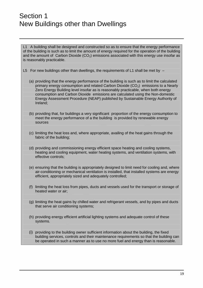
L1 A building shall be designed and constructed so as to ensure that the energy performance of the building is such as to limit the amount of energy required for the operation of the building and the amount of Carbon Dioxide (CO2) emissions associated with this energy use insofar as is reasonably practicable.
L5 For new buildings other than dwellings, the requirements of L1 shall be met by –
(a) providing that the energy performance of the building is such as to limit the calculated primary energy consumption and related Carbon Dioxide (CO2) emissions to a Nearly Zero Energy Building level insofar as is reasonably practicable, when both energy consumption and Carbon Dioxide emissions are calculated using the Non-domestic Energy Assessment Procedure (NEAP) published by Sustainable Energy Authority of Ireland;
(b) providing that, for buildings a very significant proportion of the energy consumption to meet the energy performance of a the building is provided by renewable energy sources
(c) limiting the heat loss and, where appropriate, availing of the heat gains through the fabric of the building;
(d) providing and commissioning energy efficient space heating and cooling systems, heating and cooling equipment, water heating systems, and ventilation systems, with effective controls;
(e) ensuring that the building is appropriately designed to limit need for cooling and, where air-conditioning or mechanical ventilation is installed, that installed systems are energy efficient, appropriately sized and adequately controlled;
(f) limiting the heat loss from pipes, ducts and vessels used for the transport or storage of heated water or air;
(g) limiting the heat gains by chilled water and refrigerant vessels, and by pipes and ducts that serve air conditioning systems;
(h) providing energy efficient artificial lighting systems and adequate control of these systems.
(i) providing to the building owner sufficient information about the building, the fixed building services, controls and their maintenance requirements so that the building can be operated in such a manner as to use no more fuel and energy than is reasonable.
20
1.1 Limitation of Primary Energy Use
and CO2 emissions
1.1.1 This Section provides guidance on
how to show compliance with the
requirements in relation to primary energy
consumption and CO2 emissions specified in
Regulation L5(a). This framework enables the
use of either a simplified building energy
method or an approved alternative method.
This framework is published by Sustainable
Energy Authority of Ireland (SEAI) and
calculates the energy consumption and CO2
emissions associated with a standardised use
of a building. The energy consumption is
expressed in terms of kilowatt hours per
square metre floor area per year (kWh/m2/yr)
and the CO2 emissions expressed in terms of
kilograms of CO2 per square metre floor area
per year (kg CO2/m2/yr). Full details of the
framework are available on the SEAI website
at http://www.seai.ie
The NEAP modelling guide, also available on
the SEAI website, describes the NEAP
methodology. The calculation is based on the
energy balance taking into account a range of
factors that contribute to annual energy
usage and associated CO2 emissions for the
provision of space heating, cooling, water
heating, ventilation and lighting of buildings.
The NEAP framework is in accordance with
Annex I of the Energy Performance of
Buildings Directive (recast) and takes account
of:
Thermal characteristics of the building
(shell and internal partitions, etc.); this
includes air tightness
Heating installation and hot water supply,
including their thermal characteristics
Air-conditioning installation
Natural and mechanical ventilation
Built-in lighting installation
Position and orientation of buildings,
including outdoor climate
Passive solar systems and solar
protection
Indoor climatic conditions, including the
designed indoor climate
The calculation also deals with the influence
of the following aspects of energy
performance, where relevant:
Active solar systems, and other heating
and electricity systems based on
renewable energy sources
Electricity produced by combined heat
and power
District or block heating or cooling
systems
Natural lighting
1.1.2 The performance criteria are based
on the relative values of the calculated
primary energy consumption and CO2
emissions of a building being assessed, and
similar calculated values for a Reference
Building. Details of the performance
parameters for the Reference Building are
given in Appendix C.
21
The criteria are determined as follows:
Primary energy consumption and CO2
emissions for both the proposed building
and the reference building are calculated
using NEAP.
The calculated primary energy
consumption of the proposed building is
divided by that of the reference building,
the result being the energy performance
coefficient (EPC) of the proposed building.
To demonstrate that an acceptable
Primary Energy consumption rate has
been achieved, the calculated EPC of the
building being assessed should be no
greater than the Maximum Permitted
Energy Performance Coefficient (MPEPC).
The MPEPC is 1.0.
The calculated CO2 emission rate of the
proposed building is divided by that of the
reference building, the result being the
carbon performance coefficient (CPC) of
the proposed building. To demonstrate
that an acceptable CO2 emission rate has
been achieved, the calculated CPC of the
building being assessed should be no
greater than the Maximum Permitted
Carbon Performance Coefficient
(MPCPC). The MPCPC is 1.15.
Each method within the NEAP framework will
calculate the EPC and CPC of the building
being assessed and clearly indicate whether
compliance with the requirements of
Regulation L5(a) has been achieved.
The MPEPC and MPCPC represent an
improvement in the order of 60% over a
similar Part L 2008 building with 20% of its
energy provided from onsite or nearby
renewables. and provide the numerical
indicator for Nearly Zero Energy Buildings.
1.1.3 The requirements that the calculated
EPC and CPC do not exceed the MPEPC
and MPCPC respectively, applies to the
constructed building. It is considered good
practice for designers to calculate the EPC
and CPC at early design stage in order to
assess alternative design approaches and to
ensure that the EPC and CPC requirements
can be achieved by the constructed building.
It is also open to professional bodies or other
industry interests to develop model building
designs that can confidently be adopted
without the need to calculate EPC and CPC
at design stage. However, the use of
constructions and service systems which
have been assessed at design stage, or other
model designs, does not preclude the need to
verify compliance by calculating the EPC and
CPC when all relevant details of the final
construction are known. The use of design
management programme and standards such
as SEAI Excellence in Energy Efficient
Design (EXEED) programme and Clause 8 of
I.S. 399 Energy Efficient Design Management
can also be used to support the design
process for energy efficient buildings.
1.1.4 The use of renewable and low
carbon technologies, such as solar hot water,
biomass (e.g. wood and wood pellets) and
heat pumps, whether provided to meet the
requirements of this Part of the Building
Regulations (see Section 1.2) or provided as
additional to meeting that requirement, can
facilitate compliance with the requirements in
relation to primary energy use and CO2
emissions. As defined, primary energy for the
calculation of the EPC and CPC does not
include energy derived from on-site
renewable energy technologies. In addition,
as renewable energy technologies generally
are characterised by zero, or greatly reduced,
CO2 emissions, the calculated EPC and/or
CPC are reduced by the extent that they
22
replace traditional fossil fuels. For certain
types of buildings, use of renewables may
prove the most practical approach to
achieving compliance. The use of centralised
renewable energy sources contributing to a
heat distribution system serving all buildings
in a development or campus may prove to be
more practicable than providing separate
renewable energy for each new building or
new unit individually.
1.2 Renewable Energy Technologies
1.2.1 This section gives guidance on the
minimum level of renewable technologies to
be provided to show compliance with
Regulation L5 (b). Renewable Energy Ratio
(RER) is the ratio of the primary energy from
renewable energy sources to total primary
energy as defined and calculated in NEAP.
The following represents a very significant
level of energy provision from renewable
energy technologies in order to satisfy
Regulation L5 (b); -
Where the MPEPC of 1.0 and MPCPC of
1.15 is achieved an RER of 0.20
represents a very significant level of
energy provision from renewable energy
technologies
Where an EPC of 0.9 and a CPC of 1.04 is
achieved an RER of 0.10 represents a
very significant level of energy provision
from renewable energy technologies
For the purposes of this Section, “renewable
energy technologies” means technology
products or equipment that supply energy
derived from renewable energy sources, e.g.
solar thermal systems, on-site solar
photovoltaic systems, biomass systems,
systems using biofuels, heat pumps,
combined heat and power, aerothermal,
geothermal, hydrothermal, wind, biomass and
biogases; and other on-site renewables.
1.2.2 Where a building or campus
contains more than one new building,
reasonable provision would be to show that:
every individual new building should meet
the minimum provision from renewable
energy technologies specified in
paragraph 1.2.1 above; or
the average contribution of renewable
technologies to each new building other
than a dwelling in the development or
campus should meet that minimum level
of provision.
1.2.3 The calculation methodology as
described in NEAP will calculate the minimum
level of energy provision from renewable
technologies.
All ancillary storage equipment and access
provisions required to support and operate
renewable energy technologies should be
fully installed and commissioned.
In the case of systems based on biofuels or
biomass, appliances must be designed to run
on these fuels only, i.e. incapable of providing
thermal energy from fossil fuels, to be
accepted as renewable technology for the
purposes of this Regulation. For example, a
boiler which could operate on either fossil fuel
oil or a biofuel mixture would not be
considered to be a renewable technology.
Similarly a boiler capable of utilising coal or
23
peat, in addition to a biomass fuel would not
be considered a renewable technology.
1.2.4 The use of centralised renewable
energy sources contributing to a heat
distribution system serving all new building
units other than dwellings on a campus or
part of a development, may prove to be more
practicable than providing separate
renewable energy for each building
individually.
1.2.5 As an alternative to providing the
RER (Renewable Energy Ratio) as outlined in
sub-section 1.2.1 the use of a combined heat
and power (CHP) system which contributes to
the space and water heating energy use
would be acceptable.
The primary energy savings due to the use of
CHP should be equivalent to the RER of 0.20
or 0.10 as applicable contributing to the
thermal energy use within the building. The
calculation methodology for the primary
energy saving contribution is provided in the
NEAP calculation.
The design of the CHP system should take
account of the output rating of the appliance
and the design thermal profile for the
development for which it is designed. It
should be suitable for the building application
(simultaneous electrical and thermal profile
requirements) and not oversized.
Further guidance with regards to the design
of CHP systems is available in CIBSE Manual
AM 12 Combined Heat and Power in
Buildings. Section 4.4 of CIBSE Manual AM
12 details an operating model for CHP sizing
and recommends the use of an hour by hour
model over a whole year with heat and
electricity demand profiles representing an
average year.
The optimum size of the CHP plant should
maximise the running hours without requiring
the shutdown of the unit or rejection of
surplus heat as described in CIBSE Manual
AM 12.
1.2.6 Renewable energy technologies
should be installed with the appropriate
controls to optimize their sequencing and
operation.
1.2.7 Part D of the Building Regulations
requires that all works be carried out with
proper materials and in a workmanlike
manner. “Materials” includes products,
components and items of equipment, and
guidance is provided on how products,
components and items of equipment can be
shown to be “proper materials”.
Renewable technologies should satisfy the
requirements of Part D in the same way as
other construction products and materials. A
range of standards applicable to renewable
energy technologies are given in the
“Standards and publications” Section in this
document
1.2.8 To ensure that works are carried out
in a “workmanlike manner”, the design and
installation of renewable energy systems to
comply with this guidance should be carried
out by a person qualified, trained and with
appropriate experience to carry out such
work.
1.2.9 Where appropriate the National
Standards Authority of Ireland’s SR 50-2:
2011 Code of practice for building services -
Part 2: Solar panels may be used for
guidance on the installation of solar thermal
system.
24
1.3 Building Fabric
1.3.1 General
1.3.1.1 This section gives guidance on
acceptable levels of provision to ensure that
heat loss through the fabric of a building is
limited insofar as reasonably practicable.
Guidance is given on four main issues: -
insulation levels to be achieved by the
plane fabric elements (sub-section 1.3.2);
thermal bridging (sub-section 1.3.3); and
limitation of air permeability (sub-section
1.3.4).
limiting the effects of solar gain and
overheating (sub-sections 1.3.5 and
1.3.6).
1.3.1.2 Unheated areas which are wholly or
largely within the building structure and are
not subject to excessive air-infiltration or
ventilation, e.g. stairwells, corridors in
buildings containing retail units, may be
considered as within the insulated fabric. In
that case, if the external fabric of these areas
is insulated to the same level as that
achieved by equivalent adjacent external
elements, no particular requirement for
insulation between a conditioned area and
unconditioned areas would arise. It should be
noted that heat losses to such unheated
areas are taken into account by the NEAP
methodology in the calculation of the unit
EPC and CPC (see Section 1.1).
1.3.2 Fabric Insulation
1.3.2.1 The derivation of U-values, including
those applicable where heat loss is to an
unheated space, is dealt with in Paragraphs
0.3.5 to 0.3.8 and Appendix A.
1.3.2.2 In order to limit heat loss through the
building fabric reasonable provision should be
made to limit transmission heat loss by plane
elements of the building fabric. Acceptable
levels of thermal insulation for each of the
plane elements of the building to achieve this
are specified in terms of average area-
weighted U-value (Um) in Table 1 (Column 2)
for each fabric element type. These values
can be relaxed for individual elements or
parts of elements where considered
necessary for design or construction reasons.
Maximum acceptable values for such
elements or parts of elements are specified in
Column 3 of Table 1. Where this relaxation is
availed of, the average area weighted values
given in Column 2 continue to apply and
compensatory insulation measures may be
necessary for other elements or parts of
elements of that type to ensure that these are
met. Where the source of space heating is
underfloor heating, a floor U-value of 0.15
W/m2K should generally be satisfactory.
1.3.2.3 Reasonable provision would also be
achieved if the total heat loss through the
roof, wall and floor elements did not exceed
that which would be the case if each of the
area weighted average U-value (Um) set out
in Table 1 were achieved for these elements
individually. Where this approach is chosen,
the values for individual elements or sections
of elements given in Table 1 (Column 3) also
apply. For ground floors or exposed floors
incorporating underfloor heating, the
guidance in paragraph 1.3.2.2 applies.
1.3.2.4 The area of openings provided
should take account of the level of daylight
provision appropriate to the building. BS8206-
2:2008 and CIBSE Lighting Guide (LG10),
25
give advice on adequate daylight
provision.Natural daylight should be
optimised where practical, taking into account
the advice of LG10 and BS8206.
Care should be taken in the selection and
installation of glazed systems to avoid the risk
of condensation. Guidance can be obtained
from BRE Report No 262. Thermal insulation:
avoiding risks, published by BRE and
Appendix D.
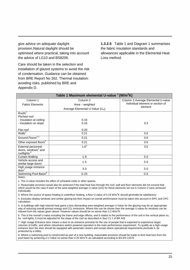
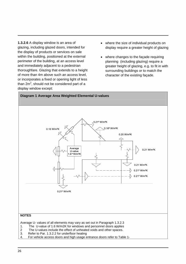
1.3.2.5 Table 1 and Diagram 1 summarises
the fabric insulation standards and
allowances applicable in the Elemental Heat
Loss method.
Table 1 Maximum elemental U-value 1 (W/m2K)
Column 1
Fabric Elements
Column 2
Area – weighted
Average Elemental U-Value (Um)
Column 3 Average Elemental U-value Individual element or section of
element
Roofs2
Pitched roof - Insulation at ceiling - Insulation on slope Flat roof
0.16 0.16
0.20
0.3
Walls2 0.21 0.6
Ground Floors2,3
0.21 0.6
Other exposed floors2 0.21 0.6
External personnel doors, windows
4 and
rooflights,6
1.65
3.0
Curtain Walling 1.8 3.0
Vehicle access and similar large doors
1.5 3.0
High usage entrance door
7
3.0 3.0
Swimming Pool Basin8 0.25 0.6
Notes:
1. The U-value includes the effect of unheated voids or other spaces.
2. Reasonable provision would also be achieved if the total heat loss through the roof, wall and floor elements did not exceed that which would be the case if each of the area weighted average U-value (Um) for these elements set out in Column 2 were achieved individually.
3. Where the source of space heating is underfloor heating, a floor U-value of 0.15 W/m2K should generally be satisfactory.
4. Excludes display windows and similar glazing but their impact on overall performance must be taken into account in EPC and CPC calculation.
5. In buildings with high internal heat gains a less demanding area-weighted average U-Value for the glazing may be an appropriate way of reducing overall primary energy and CO2 emissions. Where this can be shown then the average U-value for windows can be relaxed from the values given above. However values should be no worse than 2.2 W/m
2K.
6. This is the overall U-value including the frame and edge effects, and it relates to the performance of the unit in the vertical plane so, for roof-lights, it must be adjusted for the slope of the roof as described in Sect 11.1 of BR 443
7. High Usage Entrance door means a door to an entrance primarily for the use of people that is expected to experience larger volumes of traffic, and where robustness and/or powered operation is the main performance requirement. To qualify as a high-usage entrance door the door should be equipped with automatic closers and except where operational requirements preclude it, be protected by a lobby.
8. Where a swimming pool is constructed as part of a new building, reasonable provision should be made to limit heat loss from the pool basin by achieving a U Value no worse than 0.25 W/m
2K as calculated according to BS EN 13370
26
1.3.2.6 A display window is an area of
glazing, including glazed doors, intended for
the display of products or services on sale
within the building, positioned at the external
perimeter of the building, at an access level
and immediately adjacent to a pedestrian
thoroughfare. Glazing that extends to a height
of more than 4m above such an access level,
or incorporates a fixed or opening light of less
than 2m2, should not be considered part of a
display window except:
where the size of individual products on
display require a greater height of glazing
where changes to the façade requiring
planning (including glazing) require a
greater height of glazing, e.g. to fit in with
surrounding buildings or to match the
character of the existing façade.
Diagram 1 Average Area Weighted Elemental U-values
NOTES Average U- values of all elements may vary as set out in Paragraph 1.3.2.3 1. The U-value of 1.6 W/m2K for windows and personnel doors applies 2 The U-values include the effect of unheated voids and other spaces. 3. Refer to Par. 1.3.2.2 for underfloor heating 4. For vehicle access doors and high usage entrance doors refer to Table 1-
27
1.3.3 Thermal Bridging
1.3.3.1 To avoid excessive heat losses and
local condensation problems, reasonable
care should be taken to ensure continuity of
insulation and to limit local thermal bridging,
e.g. around windows, doors and other wall
openings, at junctions between elements and
other locations. In general thermal bridges
should not pose a risk of surface or interstitial
condensation. Heat loss associated with
thermal bridges is taken into account in
calculating energy use and CO2 emissions
using the NEAP methodology. See Appendix
D for further information in relation to thermal
bridging and its effect on building heat loss
and how this is taken account of in NEAP
calculations.
1.3.3.2 The following represents alternative
approaches to making reasonable provision
with regard to limitation of thermal bridging: -
(i) adopt Acceptable Construction Details
for wall constructions similar to those for
dwellings where appropriate (see
Appendix D, Table D1) and/or other
certified details (as defined in (ii) below)
for all key junctions
(ii) use certified details which have been
assessed in accordance, and comply
with Appendix D, e.g. certified by a third
party certification body such as Agrément
or equivalent; or certified by a member of
the NSAI approved thermal modellers
scheme or equivalent; or certified
thermal bridging details from an
accredited database such as the BRE
Certified Thermal Details and Products
Scheme for all key junctions
(iii) use alternative details which limit the risk
of mould growth and surface
condensation to an acceptable level as
set out in paragraph D.2 of Appendix D
for all key junctions.
Irrespective of which approach is used,
appropriate provision for on-site inspection
and related quality control procedures should
be made (see sub-sections 1.5.2 and 1.5.3).
1.3.3.3 The NEAP calculation of primary
energy use and CO2 emissions (see Section
1.1) takes account of thermal bridging effects.
In general this is done by including an
allowance for additional heat loss due to
thermal bridging
Where provision for thermal bridging is made
in accordance with option (i) of paragraph
1.3.3.2, the transmission heat loss coefficient
(HTB) should be calculated using the psi
values associated with the specific details
adopted (i.e. Tables D1 to D6 of DHPLG
Acceptable Construction Details or other
certified psi values) or default linear thermal
transmittances as provided in NEAP .
Where provision for thermal bridging is made
in accordance with option (ii) of paragraph
1.3.3.2, the transmission heat loss coefficient
(HTB) should be calculated using the psi
values associated with the certified specific
details adopted.
28
Where provision for thermal bridging is made
in accordance with option (iii) of paragraph
1.3.3.2, default linear thermal transmittances
may be used to calculate the heat loss due to
thermal bridges as provided for in NEAP.
The calculation of transmission heat loss
(HTB) coefficient is explained in Appendix D
paragraph D.3
The NEAP Modelling Guide also provides
information for the inclusion of thermal
bridges in NEAP.
1.3.4 Building envelope air permeability
1.3.4.1 To avoid excessive heat losses,
reasonable care should be taken to limit the
air permeability of the envelope of each
building. In this context, envelope is the total
area of all floors, walls (including windows
and doors), and ceilings bordering the
building, including elements adjoining other
heated or unheated spaces.
High levels of infiltration can contribute to
uncontrolled ventilation. Infiltration is unlikely
to provide adequate ventilation as required in
the correct location. It is important as air
permeability is reduced that purpose provided
ventilation is maintained.
1.3.4.2 The following represents a
reasonable approach to the design and
construction of buildings to ensure acceptable
levels of air permeability: -
(a) identify the primary air barrier elements,
(e.g. sheathing, plaster, vapour control
layer, breather membrane) at early
design stage;
(b) develop appropriate details and
performance specification to ensure
continuity of the air barrier.
Communicate these to all those
involved in the construction process.
Responsibility for construction of details
should be established;
(c) provide on-site inspection regime and
related quality control procedures so as
to ensure that the design intention is
achieved in practice.
1.3.4.3 Air pressure testing should be
carried out on buildings on completion.
See sub-section 1.5.4 for details of the test
procedure, extent of testing, use of test
results in NEAP calculations and appropriate
measures to be undertaken where the limit
set is not achieved. When tested in
accordance with the procedure referred to in
sub-section 1.5.4, a performance level of 5
m3/(h.m2) represents a reasonable upper limit
for air permeability.
1.3.4.4 In order to achieve the required
performance on completion it may be
required to carry out testing both at
completion of the shell and, again when the
fit-out is completed depending on building
complexity. In all cases testing should be
performed on building completion.
Section 5 of ATTMA document Technical
Standard L2 Measuring Air Permeability of
Building Envelopes (Non-Dwellings) provides
guidance for large complex buildings.
29
In large complex buildings where there is a
phased hand-over such as new district
general hospitals, airport terminals, large city
shopping centres over a significant time
period may be part pressure tested to match
the phasing of the development.
It is expected that many of these building
types can be broken down by department or
groups of retail outlets, for instance, which
could facilitate part pressure testing.
For large complex buildings with an envelope
area in excess of 160,000m2 such as airport
terminals, regional hospitals or large
shopping centres where it is not practical to
implement a phased pressure testing
approach, the alternative approach outlined in
Section 5.3 of ATTMA document Technical
Standard L2 Measuring Air Permeability of
Building Envelopes (Non-Dwellings) may be
adopted. In this case the designer should be
competent in air tightness design and should
confirm that this building is a special case
and that appropriate detailing and quality
control procedures will be put in place on site
to achieve an air permeability of 5 m3/(h.m2)
@50Pa.
Where lower levels of air permeability are
achieved it is important that purpose provided
ventilation is maintained. It is recommended
that ventilation systems are designed for
lower levels of air permeability. TGD F and
CIBSE Guidance B should be referenced for
ventilation guidance when designing for
buildings with lower air permeability.
1.3.5 Limiting the effects of solar gain
in summer
1.3.5.1 Buildings should be designed and
constructed so that:
(a) those occupied spaces that rely on
natural ventilation do not risk
unacceptable levels of thermal
discomfort due to overheating caused
by solar gain, and
(b) those spaces that incorporate
mechanical ventilation or cooling do not
require excessive plant capacity to
maintain the desired space conditions.
1.3.5.2 The following guidance applies to all
buildings, irrespective of whether they are air-
conditioned or not. The intention is to limit
solar gains during the summer period to
either:
(a) reduce the need for air-conditioning; or
(b) reduce the installed capacity of any air
conditioning system that is installed.
1.3.5.3 For the purposes of Part L ,
reasonable provision for limiting solar gain
through the building fabric would be
demonstrated by showing that for each space
in the building that is either occupied or
mechanically cooled, the solar gains through
the glazing aggregated over the period from
April to September inclusive are no greater
than would occur through one of the following
glazing systems with a defined total solar
energy transmittance (g-value) calculated
according to I.S. EN 410: 2011.
30
(a) For every space that is defined in
NEAP database as being side lit, the
reference case is an east-facing façade
with full width glazing to a height of
1.0m. having a framing factor of 10 per
cent and a normal solar energy
transmittance (g-value) of 0.68. For
every space that is defined in the NEAP
as being top lit, and whose average
zone height is not greater than 6m. the
reference case is a horizontal roof of
the same total area that is 10% glazed
as viewed from the inside out and
having roof lights that have a framing
factor of 25% and a normal solar
energy transmittance (g-value) of 0.68.
(b) For every space that is defined in the
NEAP database as being top lit and
whose average zone height is greater
than 6m, the reference case is a
horizontal roof of the same total area
that is 20% glazed as viewed from the
inside out and having
(c) roof-lights that have a framing factor of
15 % and a normal solar energy
transmittance (g value) of 0.46.
Note: In double-height industrial type
spaces, dirt on roof lights and internal
absorption reduce solar gains. These
effects combined with temperature
stratification will reduce the impact of
solar gains in the occupied space and
so increased roof light area may be
justified. In such situations, particular
attention to the design assessments in
Par 1.3.5.3 (b).
(d) For the purpose of this specific guidance,
an occupied space means a space that
is intended to be occupied by the same
person for a substantial part of the day.
This excludes circulation spaces and
other areas of transient occupancy
such as toilets and spaces not intended
for occupation e.g. display windows.
1.3.6. Limiting Overheating
The assessment of solar gain in Section 1.3.5
is not an assessment of the internal comfort
condition of the building as many other
factors have a bearing on comfort e.g. room
loads, thermal capacity, ventilation
provisions. CIBSE TM 52 provide
recommendations for new buildings and
adaptation strategies. It is recommended that
the designer should perform an overheating
assessment in accordance CIBSE TM 52 to
ensure overheating is avoided for normally
occupied naturally ventilated spaces. Further
guidance is provided in NEAP for carrying out
the overheating assessment.
1.3.6.1 CIBSE TM 37 provides the following
recommendations and further guidance to
reduce or avoid solar overheating:
(a) Layout: planning the layout and
orientation of buildings and rooms to
maximise the benefits of sunlight and
minimise the disadvantages.
(b) Solar shading: this may include
external, internal or mid-pane shading
devices, or solar control glazing.
(c) Thermal mass: an exposed
heavyweight structure, with a long
response time, will tend to absorb heat,
resulting in lower peak temperatures on
hot days. Night time venting and
acoustic requirements should also be
taken into account.
31
(d) Good ventilation: a reasonable level of
ventilation will always be required in
buildings to maintain indoor air quality.
The ability to switch to a much higher
air change rate can be a very effective
way to control solar overheating. E.g.
cross ventilation, stack ventilation or
mechanical ventilation
(e) Reducing internal gains: e.g. energy
efficient equipment, lamps and
luminaires, and controls
(f) Cooling: free cooling, mechanical
cooling or air conditioning.
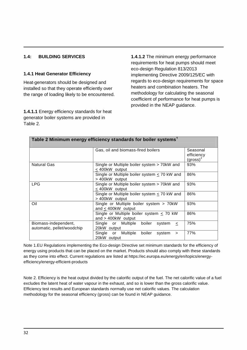
32
1.4: BUILDING SERVICES
1.4.1 Heat Generator Efficiency
Heat generators should be designed and
installed so that they operate efficiently over
the range of loading likely to be encountered.
1.4.1.1 Energy efficiency standards for heat
generator boiler systems are provided in
Table 2.
1.4.1.2 The minimum energy performance
requirements for heat pumps should meet
eco-design Regulation 813/2013
implementing Directive 2009/125/EC with
regards to eco-design requirements for space
heaters and combination heaters. The
methodology for calculating the seasonal
coefficient of performance for heat pumps is
provided in the NEAP guidance.
Table 2 Minimum energy efficiency standards for boiler systems1
Gas, oil and biomass-fired boilers Seasonal
efficiency (gross)
2
Natural Gas Single or Multiple boiler system > 70kW and < 400kW output
93%
Single or Multiple boiler system < 70 kW and > 400kW output
86%
LPG Single or Multiple boiler system > 70kW and < 400kW output
93%
Single or Multiple boiler system < 70 kW and > 400kW output
86%
Oil Single or Multiple boiler system > 70kW and < 400kW output
93%
Single or Multiple boiler system < 70 kW and > 400kW output
86%
Biomass-independent, automatic, pellet/woodchip
Single or Multiple boiler system < 20kW output
75%
Single or Multiple boiler system > 20kW output
77%
Note 1.EU Regulations implementing the Eco-design Directive set minimum standards for the efficiency of
energy using products that can be placed on the market. Products should also comply with these standards
as they come into effect. Current regulations are listed at https://ec.europa.eu/energy/en/topics/energy-
efficiency/energy-efficient-products
Note 2. Efficiency is the heat output divided by the calorific output of the fuel. The net calorific value of a fuel
excludes the latent heat of water vapour in the exhaust, and so is lower than the gross calorific value.
Efficiency test results and European standards normally use net calorific values. The calculation
methodology for the seasonal efficiency (gross) can be found in NEAP guidance.
33
1.4.2 Controls for Space Heating and Hot
Water Supply Systems
1.4.2.1 Space and water heating systems
should be effectively controlled so as to limit
energy use by these systems to that required
to satisfy user requirements and, where
appropriate, to protect the building and its
contents from damage due to low
temperatures. This section is not intended to
apply to control systems for specialist or
industrial processes.
1.4.2.2 Buildings should be provided with
zone, timing and temperature controls such
that, for space heating, each functional area
is maintained at the required temperature
only during the period when it is occupied.
Additional space heating controls may be
provided to allow heating during extended
unusual occupation hours and to provide for
sufficient background heating to prevent
condensation or frost damage when the
heating system would otherwise be switched
off.
1.4.2.3 Hot water systems should be
designed and provided with appropriate
controls so that they can be operated
efficiently. For efficient operation, hot water
systems should not be over-sized and should
be designed to avoid low-load operation of
heating plant. The layout should minimize the
length of circulation loops and minimize the
length and diameter of dead legs. Designers
should have particular regard to the need to
limit the risk of promoting the growth of
legionella bacteria. Local instantaneous
heaters should be used, where appropriate.
1.4.2.4 For buildings with a heat generator
with an effective rated output for space
heating purposes of more than 70kW a full
building management system (BMS) should
be installed to control the heat generator(s). A
full BMS linked to the heating plant will
provide sequential controls of multiple heat
generators, full zoned time control and
weather compensation where applicable,
frost protection or night set-back optimization
and monitoring and targeting.
Minimum recommended controls for heat
generator systems are specified in Tables 3,
4 and 5.
1.4.2.5 For buildings with a heat generator
with an effective rated output for space
heating purposes with an effective rated
output of over 70 kW a building automation
and control system should be installed for the
building with the following functions:
(a) continuously monitoring, analysing and
allowing for adjusting energy usage
including that provided by renewable
energy technologies;
(b) benchmarking the building’s energy
efficiency, detecting losses in efficiency
of technical building systems, and
informing the person responsible for the
facilities or technical building
management about opportunities for
energy efficiency improvement;
(c) allowing communication with connected
technical building systems and other
appliances inside the building, and
being interoperable with technical
building systems across different types
of proprietary technologies, devices and
manufacturers, and
(d) monitoring the energy provided by
renewable energy technologies.
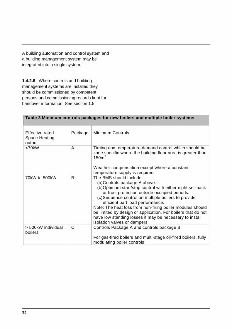
34
A building automation and control system and
a building management system may be
integrated into a single system.
1.4.2.6 Where controls and building
management systems are installed they
should be commissioned by competent
persons and commissioning records kept for
handover information. See section 1.5.
Table 3 Minimum controls packages for new boilers and multiple boiler systems
Effective rated Space Heating output
Package
Minimum Controls
<70kW A Timing and temperature demand control which should be zone specific where the building floor area is greater than 150m2
Weather compensation except where a constant temperature supply is required
70kW to 500kW B The BMS should include: (a) Controls package A above. (b) Optimum start/stop control with either night set-back
or frost protection outside occupied periods. (c) Sequence control on multiple boilers to provide
efficient part load performance. Note: The heat loss from non-firing boiler modules should be limited by design or application. For boilers that do not have low standing losses it may be necessary to install isolation valves or dampers
> 500kW individual boilers
C Controls Package A and controls package B For gas-fired boilers and multi-stage oil-fired boilers, fully modulating boiler controls
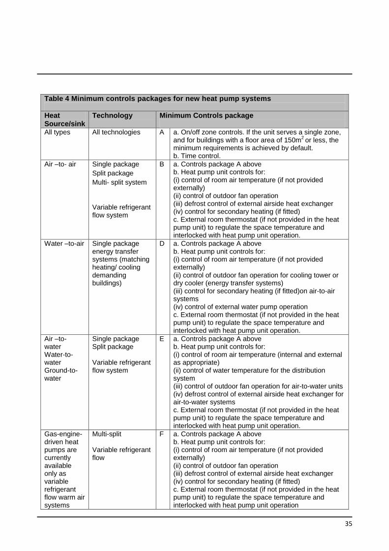
35
Table 4 Minimum controls packages for new heat pump systems
Heat Source/sink
Technology Minimum Controls package
All types All technologies A a. On/off zone controls. If the unit serves a single zone, and for buildings with a floor area of 150m
2 or less, the
minimum requirements is achieved by default. b. Time control.
Air –to- air Single package
Split package
Multi- split system
Variable refrigerant flow system
B a. Controls package A above b. Heat pump unit controls for: (i) control of room air temperature (if not provided externally) (ii) control of outdoor fan operation (iii) defrost control of external airside heat exchanger (iv) control for secondary heating (if fitted) c. External room thermostat (if not provided in the heat pump unit) to regulate the space temperature and interlocked with heat pump unit operation.
Water –to-air Single package energy transfer systems (matching heating/ cooling demanding buildings)
D a. Controls package A above b. Heat pump unit controls for: (i) control of room air temperature (if not provided externally) (ii) control of outdoor fan operation for cooling tower or dry cooler (energy transfer systems) (iii) control for secondary heating (if fitted)on air-to-air systems (iv) control of external water pump operation c. External room thermostat (if not provided in the heat pump unit) to regulate the space temperature and interlocked with heat pump unit operation.
Air –to- water Water-to-water Ground-to-water
Single package Split package Variable refrigerant flow system
E a. Controls package A above b. Heat pump unit controls for: (i) control of room air temperature (internal and external as appropriate) (ii) control of water temperature for the distribution system (iii) control of outdoor fan operation for air-to-water units (iv) defrost control of external airside heat exchanger for air-to-water systems c. External room thermostat (if not provided in the heat pump unit) to regulate the space temperature and interlocked with heat pump unit operation.
Gas-engine-driven heat pumps are currently available only as variable refrigerant flow warm air systems
Multi-split Variable refrigerant flow
F a. Controls package A above b. Heat pump unit controls for: (i) control of room air temperature (if not provided externally) (ii) control of outdoor fan operation (iii) defrost control of external airside heat exchanger (iv) control for secondary heating (if fitted) c. External room thermostat (if not provided in the heat pump unit) to regulate the space temperature and interlocked with heat pump unit operation
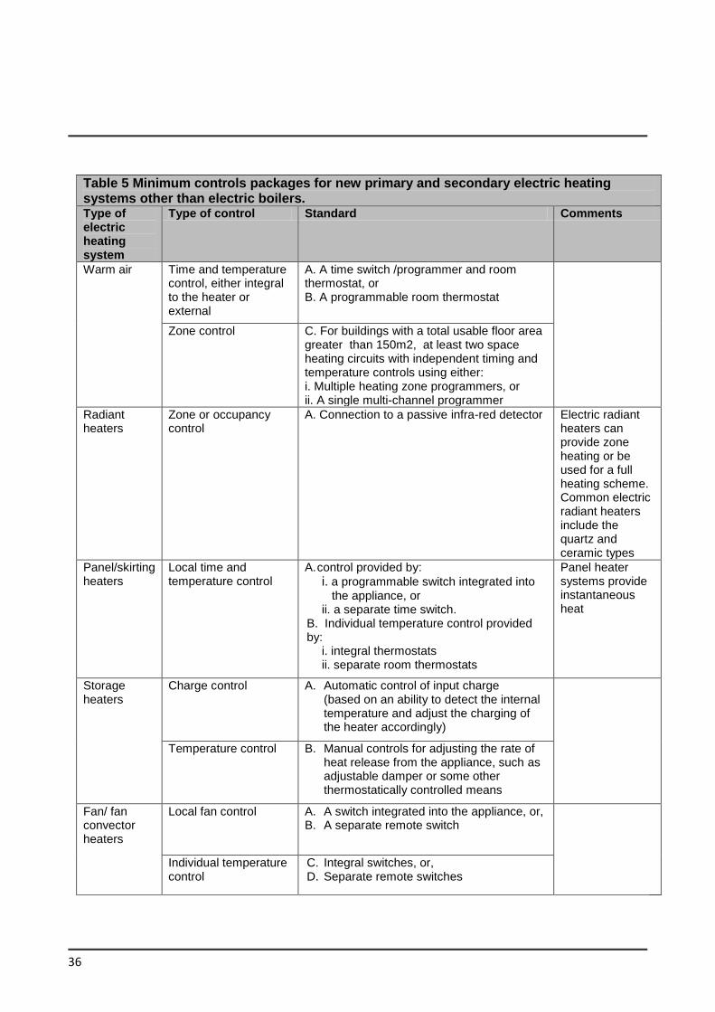
36
Table 5 Minimum controls packages for new primary and secondary electric heating systems other than electric boilers. Type of electric heating system
Type of control Standard Comments
Warm air Time and temperature control, either integral to the heater or external
A. A time switch /programmer and room thermostat, or B. A programmable room thermostat
Zone control C. For buildings with a total usable floor area greater than 150m2, at least two space heating circuits with independent timing and temperature controls using either: i. Multiple heating zone programmers, or ii. A single multi-channel programmer
Radiant heaters
Zone or occupancy control
A. Connection to a passive infra-red detector Electric radiant heaters can provide zone heating or be used for a full heating scheme. Common electric radiant heaters include the quartz and ceramic types
Panel/skirting heaters
Local time and temperature control
A. control provided by:
i. a programmable switch integrated into the appliance, or ii. a separate time switch.
B. Individual temperature control provided by:
i. integral thermostats ii. separate room thermostats
Panel heater systems provide instantaneous heat
Storage heaters
Charge control A. Automatic control of input charge (based on an ability to detect the internal temperature and adjust the charging of the heater accordingly)
Temperature control B. Manual controls for adjusting the rate of heat release from the appliance, such as adjustable damper or some other thermostatically controlled means
Fan/ fan convector heaters
Local fan control A. A switch integrated into the appliance, or, B. A separate remote switch
Individual temperature control
C. Integral switches, or, D. Separate remote switches
37
1.4.3 Air Conditioning and Mechanical
Ventilation (ACMV)
1.4.3.1 Buildings should be designed and
constructed in such a way that:
(a) the form and fabric of the building do
not result in a requirement for
excessive installed capacity of ACMV
equipment for cooling purposes, and
(b) the ventilating and cooling systems
installed are energy efficient and are
capable of being controlled to achieve
optimum energy efficiency
1.4.3.2 Natural ventilation strategies used
should be considered appropriate for the
building geometry.
Particular attention should be paid to limiting
solar gains by ensuring that areas of the
external building fabric which are susceptible
to solar gain have appropriate areas of solar
shading.
1.4.3.3 A mixed-mode building integrates the
use of air conditioning when and where it is
necessary, with use of natural ventilation
whenever it is feasible or desirable, to
maximise occupant comfort whilst reducing
energy use (compared to 'year round' use of
air conditioning).CIBSE Guide AM 13 Mixed
Mode Ventilation provides guidance on mixed
mode design.
1.4.3.4 Free cooling may be optimised in
order to minimise the need for mechanical
ventilation and air conditioning. When the
external air temperature is higher than the
space temperature the system design should
allow the provision of a minimum level of
fresh air. Enthalpy control should also be
considered to improve free cooling. The SEAI
Guide to “Relative Humidity in Data Centres”
explains how free cooling operates in the Irish
Climate. BSRIA guide BG 8/2004 Free
Cooling Systems also provides guidance on
the design of free cooling systems. Where
free cooling is used air-conditioning systems
are still required to have heat recovery
systems as required by Commission
Regulation (EU) 1253/2014 with regard to
eco-design requirements for ventilation units.
1.4.3.5 Buildings that use mechanical
ventilation or air conditioning systems should
be designed and constructed such that:
(a) the form and fabric of the building do
not result in a requirement for
excessive installed capacity of ACMV
equipment. In particular, the suitable
specification of glazing ratios and
solar shading are an important way to
limit cooling requirements (see
Section 1.3.5 and 1.3.6);
(b) components such as fans, pumps and
refrigeration equipment are
reasonably efficient and appropriately
sized so as to have no more capacity
for demand and standby than is
necessary for the task;
(c) suitable facilities are provided to
manage, control and monitor the
operation of the equipment and the
systems.
1.4.3.6 Specific fan power (SFP) of an air
distribution system means the sum of the
design circuit-watts of the system fans that
supply air and exhaust it outdoors, including
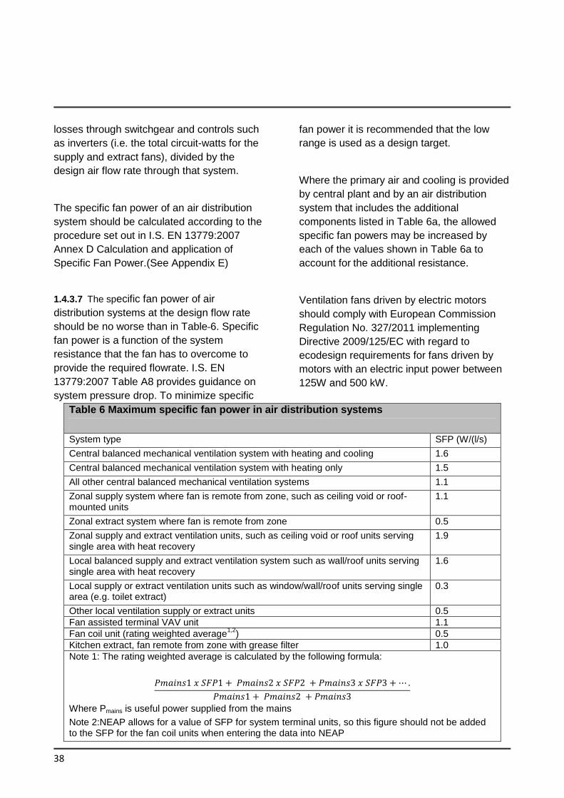
38
losses through switchgear and controls such
as inverters (i.e. the total circuit-watts for the
supply and extract fans), divided by the
design air flow rate through that system.
The specific fan power of an air distribution
system should be calculated according to the
procedure set out in I.S. EN 13779:2007
Annex D Calculation and application of
Specific Fan Power.(See Appendix E)
1.4.3.7 The specific fan power of air
distribution systems at the design flow rate
should be no worse than in Table 6. Specific
fan power is a function of the system
resistance that the fan has to overcome to
provide the required flowrate. I.S. EN
13779:2007 Table A8 provides guidance on
system pressure drop. To minimize specific
fan power it is recommended that the low
range is used as a design target.
Where the primary air and cooling is provided
by central plant and by an air distribution
system that includes the additional
components listed in Table 6a, the allowed
specific fan powers may be increased by
each of the values shown in Table 6a to
account for the additional resistance.
Ventilation fans driven by electric motors
should comply with European Commission
Regulation No. 327/2011 implementing
Directive 2009/125/EC with regard to
ecodesign requirements for fans driven by
motors with an electric input power between
125W and 500 kW.
Table 6 Maximum specific fan power in air distribution systems
System type SFP (W/(l/s)
Central balanced mechanical ventilation system with heating and cooling 1.6
Central balanced mechanical ventilation system with heating only 1.5
All other central balanced mechanical ventilation systems 1.1
Zonal supply system where fan is remote from zone, such as ceiling void or roof-mounted units
1.1
Zonal extract system where fan is remote from zone 0.5
Zonal supply and extract ventilation units, such as ceiling void or roof units serving single area with heat recovery
1.9
Local balanced supply and extract ventilation system such as wall/roof units serving single area with heat recovery
1.6
Local supply or extract ventilation units such as window/wall/roof units serving single area (e.g. toilet extract)
0.3
Other local ventilation supply or extract units 0.5
Fan assisted terminal VAV unit 1.1
Fan coil unit (rating weighted average1,2
) 0.5
Kitchen extract, fan remote from zone with grease filter 1.0
Note 1: The rating weighted average is calculated by the following formula:
Where Pmains is useful power supplied from the mains
Note 2:NEAP allows for a value of SFP for system terminal units, so this figure should not be added to the SFP for the fan coil units when entering the data into NEAP
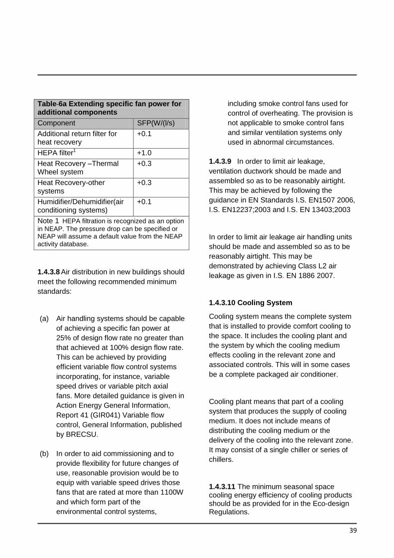
39
Table 6a Extending specific fan power for additional components
Component SFP(W/(l/s)
Additional return filter for heat recovery
+0.1
HEPA filter1 +1.0
Heat Recovery –Thermal Wheel system
+0.3
Heat Recovery-other systems
+0.3
Humidifier/Dehumidifier(air conditioning systems)
+0.1
Note 1 HEPA filtration is recognized as an option
in NEAP. The pressure drop can be specified or NEAP will assume a default value from the NEAP activity database.
1.4.3.8 Air distribution in new buildings should
meet the following recommended minimum
standards:
(a) Air handling systems should be capable
of achieving a specific fan power at
25% of design flow rate no greater than
that achieved at 100% design flow rate.
This can be achieved by providing
efficient variable flow control systems
incorporating, for instance, variable
speed drives or variable pitch axial
fans. More detailed guidance is given in
Action Energy General Information,
Report 41 (GIR041) Variable flow
control, General Information, published
by BRECSU.
(b) In order to aid commissioning and to
provide flexibility for future changes of
use, reasonable provision would be to
equip with variable speed drives those
fans that are rated at more than 1100W
and which form part of the
environmental control systems,
including smoke control fans used for
control of overheating. The provision is
not applicable to smoke control fans
and similar ventilation systems only
used in abnormal circumstances.
1.4.3.9 In order to limit air leakage,
ventilation ductwork should be made and
assembled so as to be reasonably airtight.
This may be achieved by following the
guidance in EN Standards I.S. EN1507 2006,
I.S. EN12237;2003 and I.S. EN 13403;2003
In order to limit air leakage air handling units
should be made and assembled so as to be
reasonably airtight. This may be
demonstrated by achieving Class L2 air
leakage as given in I.S. EN 1886 2007.
1.4.3.10 Cooling System
Cooling system means the complete system
that is installed to provide comfort cooling to
the space. It includes the cooling plant and
the system by which the cooling medium
effects cooling in the relevant zone and
associated controls. This will in some cases
be a complete packaged air conditioner.
Cooling plant means that part of a cooling
system that produces the supply of cooling
medium. It does not include means of
distributing the cooling medium or the
delivery of the cooling into the relevant zone.
It may consist of a single chiller or series of
chillers.
1.4.3.11 The minimum seasonal space cooling energy efficiency of cooling products should be as provided for in the Eco-design Regulations.
40
Seasonal energy efficiency ratio (SEER) as defined by Eco-design Regulations is the overall energy efficiency ratio of the air conditioner or comfort chiller, representative for the cooling season, calculated as the reference annual cooling demand divided by the annual energy consumption for cooling; - The relevant Eco-design Regulations are:-
- Commission Regulation (EU) 2016/2281 for the setting of eco-design requirements for energy-related products, with regard to eco-design requirements for air heating products, cooling products, high temperature process chillers and fan coil units
- -Commission Regulation (EU) No
206/2012 with regard to eco-design
requirements for air conditioners and
comfort fans
1.4.4 ACMV Controls
1.4.4.1 Systems should be provided with
appropriate controls to enable the
achievement of reasonable standards of
energy efficiency in use, in normal
circumstances, the following features would
be appropriate for air-conditioning and
mechanical ventilation systems and controls
(a) The systems should be divided into
separate control zones to correspond to
each area of the building that has a
significantly different solar exposure or
type of use; and
(b) Each separate control zone should be
capable of independent timing and
temperature control and, where
appropriate, ventilation and air
recirculation rate; and
(c) The provision of the service should
respond to the requirements of the space
it serves. If both heating and cooling are
provided they should be controlled so as
not to operate simultaneously unless
required for humidification control.
(d) Central plant should only operate as and
when the zone systems require it. The
default condition should be off.
(e) In addition to these general control
provisions the systems should meet
general control and efficiency standards
as set out in Pars 1.4.4.2 and 1.4.4.3
1.4.4.2 A minimum controls package should
be provided as in Table 7 for air distribution-
systems.
1.4.4.3 Where the effective rated output of
the air-conditioning systems is greater than
70kW a Building Management System should
be installed which provides centralized
control. A full BMS linked to the air
conditioning systems will provide full zoned
time control and weather compensation
where applicable, frost protection or night set-
back optimization. In larger or more complex
buildings, the guidance contained in CIBSE
Guide H: Building Control Systems may also
be followed.
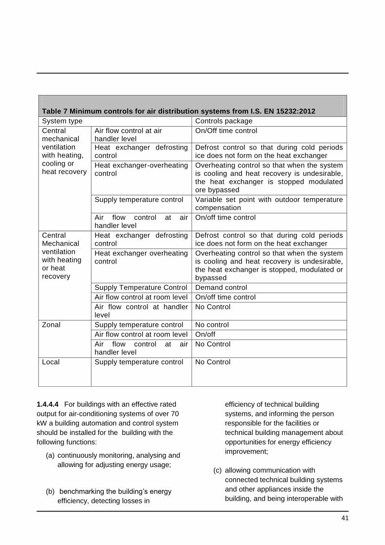
41
1.4.4.4 For buildings with an effective rated
output for air-conditioning systems of over 70
kW a building automation and control system
should be installed for the building with the
following functions:
(a) continuously monitoring, analysing and
allowing for adjusting energy usage;
(b) benchmarking the building’s energy
efficiency, detecting losses in
efficiency of technical building
systems, and informing the person
responsible for the facilities or
technical building management about
opportunities for energy efficiency
improvement;
(c) allowing communication with
connected technical building systems
and other appliances inside the
building, and being interoperable with
Table 7 Minimum controls for air distribution systems from I.S. EN 15232:2012
System type Controls package
Central mechanical ventilation with heating, cooling or heat recovery
Air flow control at air handler level
On/Off time control
Heat exchanger defrosting control
Defrost control so that during cold periods ice does not form on the heat exchanger
Heat exchanger-overheating control
Overheating control so that when the system is cooling and heat recovery is undesirable, the heat exchanger is stopped modulated ore bypassed
Supply temperature control Variable set point with outdoor temperature compensation
Air flow control at air handler level
On/off time control
Central Mechanical ventilation with heating or heat recovery
Heat exchanger defrosting control
Defrost control so that during cold periods ice does not form on the heat exchanger
Heat exchanger overheating control
Overheating control so that when the system is cooling and heat recovery is undesirable, the heat exchanger is stopped, modulated or bypassed
Supply Temperature Control Demand control
Air flow control at room level On/off time control
Air flow control at handler level
No Control
Zonal Supply temperature control No control
Air flow control at room level On/off
Air flow control at air handler level
No Control
Local Supply temperature control No Control
42
technical building systems across
different types of proprietary
technologies, devices and
manufacturers, and
(d) monitoring the energy provided by
renewable energy technologies.
A building automation and control system and
a building management system may be
integrated into a single system.
1.4.4.5 Where controls and building
management systems are installed they
should be commissioned by competent
persons and commissioning records kept for
handover information.
1.4.5 Insulation of storage vessels, pipes
and ducts
1.4.5.1 This section only applies to pipes,
ducts and vessels for the provision of space
heating, space cooling (including chilled
water and refrigerant pipework) and hot water
supply for normal occupation. It does not
apply to pipes, ducts and vessels associated
with specialist or industrial processes.
1.4.5.2 Hot water storage vessels, pipes and
ducts associated with the provision of heating
and hot water in a building should be
insulated to limit heat loss, except where the
heat flow through the wall of the pipe, duct or
vessel is always useful in conditioning the
surrounding space. Storage vessels for
chilled water and refrigerant, and pipes and
ducts that serve air-conditioning systems
should be insulated to limit heat gain from the
surrounding environment.
1.4.5.3 Provision of insulation to pipes, ducts and storage vessels, in accordance with the standards specified in BS 5422: 2009, should adequately limit heat loss or heat gain, as appropriate. The appropriate insulation level for storage vessels should be taken as that given in BS 5422: 2009 for flat surfaces.
1.4.5.4 It should be noted that water pipes
and storage vessels in unheated areas will
generally need to be insulated for the
purpose of protection against freezing.
Guidance on suitable protection measures is
given in Technical Guidance Document G
and BRE Report 262 Thermal insulation;-
avoiding risks.
1.4.6 Artificial Lighting
1.4.6.1 This Section provides guidance for the following types of lighting:
• general interior lighting
• display lighting
1.4.6.2 For the purposes of this section the definitions for lighting are provided in Appendix F.
1.4.6.3 General purpose artificial lighting systems shall be designed and controlled so as to ensure the efficient use of energy for this purpose.
1.4.6.4 The aim of lighting controls should be to encourage the maximum use of daylight and to avoid unnecessary artificial lighting, particularly when spaces are unoccupied, having regard to the need to ensure that the operation of automatically switched lighting systems does not endanger occupants in a building.BS 8206: Part 2: 2008 Code of Practice for daylight and CIBSE Lighting
43
Guide LG 10 gives advice on adequate daylight provision.
1.4.6.5 Lighting controls in buildings should follow the guidance in BRE Digest 498 Selecting Lighting Controls. Display lighting where provided should be controlled on dedicated circuits that can be switched off when not required.
Adequate control depends on the nature and use pattern of the building. This may be achieved by one, or more, of the following means, used alone or in combination, as appropriate. Detailed guidance on the application of the following methods is provided in Table 2 of BRE Digest 498 Selecting Lighting Controls.
(a) local manually operated switches in easily accessible positions within each working area or at boundaries between working areas and general circulation routes. The distance on plan from any local switch to the luminaries it controls should generally be not more than six metres, or twice the height of the light fitting above the floor if this is greater;
(b) daylight-linked photo-electric switching or dimming for lighting adjacent to windows or other sources of natural light;
(c) remote controlled switches operated by infrared transmitter, sonic, ultrasonic or telephone handset controls;
(d) automatic switching systems which switch the lighting off when they sense the absence of occupants;
(e) time-controlled switches.
All the above types of control can form part of a lighting or building energy management system. These enable a range of additional
functions including remote operation and management of lighting systems. 1.4.6.6 Lighting in new buildings should meet the minimum standards for:
(i) efficacy (averaged over the whole area of the applicable type of space in the building) and controls in column 3 of Table 8
OR
(ii) maximum Lighting Energy Numeric Indicator (LENI) (kWh/m2/year) listed in Table 9. LENI is based on BS EN 15193:2007 Energy Performance of Buildings - Energy Requirements for Lighting. The LENI should be calculated using the procedure in Appendix F to meet the maximum values in Table 9.
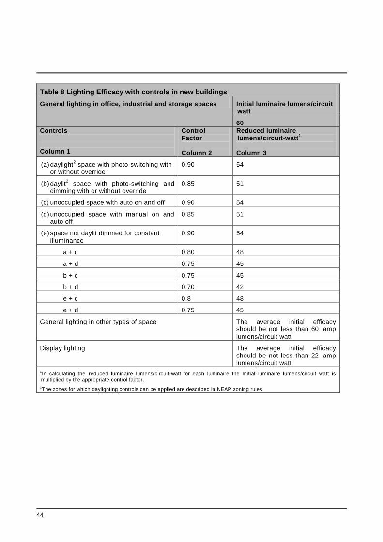
44
Table 8 Lighting Efficacy with controls in new buildings
General lighting in office, industrial and storage spaces Initial luminaire lumens/circuit watt
60
Controls
Column 1
Control Factor Column 2
Reduced luminaire lumens/circuit-watt
1
Column 3
(a) daylight2 space with photo-switching with
or without override 0.90 54
(b) daylit2 space with photo-switching and
dimming with or without override 0.85 51
(c) unoccupied space with auto on and off 0.90 54
(d) unoccupied space with manual on and auto off
0.85 51
(e) space not daylit dimmed for constant illuminance
0.90 54
a + c 0.80 48
a + d 0.75 45
b + c 0.75 45
b + d 0.70 42
e + c 0.8 48
e + d 0.75 45
General lighting in other types of space The average initial efficacy should be not less than 60 lamp lumens/circuit watt
Display lighting The average initial efficacy should be not less than 22 lamp lumens/circuit watt
1In calculating the reduced luminaire lumens/circuit-watt
for each luminaire the Initial luminaire lumens/circuit watt is
multiplied by the appropriate control factor.
2The zones for which daylighting controls can be applied are described in NEAP zoning rules
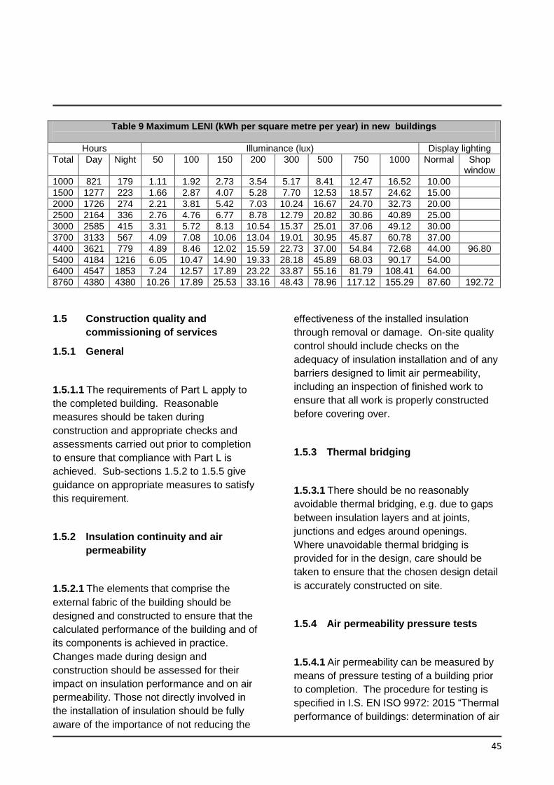
45
Table 9 Maximum LENI (kWh per square metre per year) in new buildings
Hours Illuminance (lux) Display lighting
Total Day Night 50 100 150 200 300 500 750 1000 Normal Shop window
1000 821 179 1.11 1.92 2.73 3.54 5.17 8.41 12.47 16.52 10.00
1500 1277 223 1.66 2.87 4.07 5.28 7.70 12.53 18.57 24.62 15.00
2000 1726 274 2.21 3.81 5.42 7.03 10.24 16.67 24.70 32.73 20.00
2500 2164 336 2.76 4.76 6.77 8.78 12.79 20.82 30.86 40.89 25.00
3000 2585 415 3.31 5.72 8.13 10.54 15.37 25.01 37.06 49.12 30.00
3700 3133 567 4.09 7.08 10.06 13.04 19.01 30.95 45.87 60.78 37.00
4400 3621 779 4.89 8.46 12.02 15.59 22.73 37.00 54.84 72.68 44.00 96.80
5400 4184 1216 6.05 10.47 14.90 19.33 28.18 45.89 68.03 90.17 54.00
6400 4547 1853 7.24 12.57 17.89 23.22 33.87 55.16 81.79 108.41 64.00
8760 4380 4380 10.26 17.89 25.53 33.16 48.43 78.96 117.12 155.29 87.60 192.72
1.5 Construction quality and
commissioning of services
1.5.1 General
1.5.1.1 The requirements of Part L apply to
the completed building. Reasonable
measures should be taken during
construction and appropriate checks and
assessments carried out prior to completion
to ensure that compliance with Part L is
achieved. Sub-sections 1.5.2 to 1.5.5 give
guidance on appropriate measures to satisfy
this requirement.
1.5.2 Insulation continuity and air
permeability
1.5.2.1 The elements that comprise the
external fabric of the building should be
designed and constructed to ensure that the
calculated performance of the building and of
its components is achieved in practice.
Changes made during design and
construction should be assessed for their
impact on insulation performance and on air
permeability. Those not directly involved in
the installation of insulation should be fully
aware of the importance of not reducing the
effectiveness of the installed insulation
through removal or damage. On-site quality
control should include checks on the
adequacy of insulation installation and of any
barriers designed to limit air permeability,
including an inspection of finished work to
ensure that all work is properly constructed
before covering over.
1.5.3 Thermal bridging
1.5.3.1 There should be no reasonably
avoidable thermal bridging, e.g. due to gaps
between insulation layers and at joints,
junctions and edges around openings.
Where unavoidable thermal bridging is
provided for in the design, care should be
taken to ensure that the chosen design detail
is accurately constructed on site.
1.5.4 Air permeability pressure tests
1.5.4.1 Air permeability can be measured by
means of pressure testing of a building prior
to completion. The procedure for testing is
specified in I.S. EN ISO 9972: 2015 “Thermal
performance of buildings: determination of air
46
permeability of buildings: fan pressurization
method”. Detailed guidance on testing
procedure is given in ATTMA TSL2
publication “Measuring air permeability of
Building Envelopes” and additional guidance
is provided in CIBSE Technical Manual TM
23 “Testing Buildings for Air leakage”. The
preferred test method is that controllable
ventilator grills should be temporarily sealed
rather than just closed. When testing there
should be an unobstructed route for the air to
flow from the fans. All internal areas of the
building should be connected by adequate
openings at least the area of a fully opened
single leaf door, to achieve even internal
pressure distribution of the tested building.
Permeability is calculated by dividing the air
leakage rate in m3/hr by the envelope area in
m2. The performance is assessed at 50
Pascals pressure difference. Guidance on
appropriate extent of testing is given in
paragraphs 1.5.4.2 and 1.5.4.3.
1.5.4.2 Subject to the guidance in paragraph
1.3.4.4, air pressure testing should be carried
on all buildings, as outlined in paragraphs
1.5.4.3 to 1.5.4.5 to show attainment of
backstop value of 5 m3/hr/m2. The tests
should be carried out by a person certified by
an independent third party to carry out this
work, e.g.Irish National Accreditation Body or
National Standards Authority of Ireland
certified or equivalent. The test report should
contain at least the information specified in
Section 7 of I.S. EN ISO 9972: 2015.
1.5.4.3 If the measured air change rates are
not worse than the criterion set out in
paragraph 1.3.4.3, the test results should be
taken as satisfactory evidence that the
requirements of Part L5(c), insofar as it
relates to air tightness, has been
demonstrated for this building. If satisfactory
performance is not achieved in a particular
test, then remedial measures should be
carried out on the test building and a new test
carried out. This should be repeated until the
building achieves the criterion set out in
paragraph 1.3.4.3.
1.5.4.4 Where the air permeability assumed
for the NEAP calculations is better than the
value derived from pressure test results, a
check calculation should be carried out to
show that the calculated EPC and CPC using
the measured air permeability (after any
remedial works to satisfy paragraph 1.3.4.4, if
such are necessary) are not worse than the
MPEPC and MPCPC respectively. If
necessary, additional remedial works or other
measures should be carried out to ensure
that this criterion is also met. Where further
remedial works to reduce air permeability are
undertaken, a further test would be necessary
to verify revised air permeability figure to be
used in revised NEAP calculations.
1.5.4.5 Air pressurisation test reports should
be retained by the developer of the building
as proof of performance, and copies included
in the user information referred to in Section
1.6.
1.5.5 Commissioning space and water
heating systems, Air-Conditioning and
Mechanical Ventilation systems and
Renewable systems
1.5.5.1 The heating and hot water system(s),
air conditioning and mechanical ventilation
systems and renewable systems should be
commissioned so that at completion, the
system(s) and their controls are left in the
47
intended working order and can operate
efficiently for the purposes of the
conservation of fuel and energy. The design
should be reviewed to ensure systems, plant,
equipment and components meet
commissionability, maintainability,
functionality, usability and operational
performance requirements The key elements
of a commissioning plan, identifying the
systems that need to be tested and the tests
that will be carried out should be developed
at the design stage. The BSRIA Job Book A
project framework for engineering services
BG1/2009 provides further useful information
on commissioning of buildings.
1.5.5.2 Ductwork leakage testing should be
carried out on Class C and Class D ductwork
where required by and in accordance with the
procedures set out in B&ES DW/143 and
B&ES DW/144 on systems served by fans
with a design flow greater than 1m3/s.
If ductwork fails to meet the leakage
standard, remedial work should be carried out
as necessary to achieve satisfactory
performance in retests and further ductwork
sections should be tested as set out in
DW/143
1.6 User information
1.6.1 General
The owner or occupants of the building
should be provided with sufficient information
about the building, the fixed building services
and their maintenance requirements so that
the building can be operated in such a
manner as to use no more fuel and energy
than is reasonable in the circumstances. A
way of complying would be to provide a
suitable set of operating and maintenance
instructions aimed at achieving economy in
the use of fuel and energy in a way that the
building owner or occupants can understand
as applicable eg. manuals and/or digital
media. The instructions should be directly
related to the particular system(s) installed in
the building. Without prejudice to the need to
comply with health and safety requirements,
the instructions should explain to the owner
or occupier of the building how to operate the
system(s) efficiently. This should include: -
(a) drawings and manuals necessary to
operate and maintain the energy using
equipment in the buildings e.g. boilers,
chillers, pumps and fans, lighting,
building management systems
(b) the monitoring of energy use and
making of adjustments to the control
settings for energy using equipment;
(c) routine maintenance is needed to
enable operating efficiency to be
maintained at a reasonable level
through the service life(lives) of the
system(s).
(d) details of the renewable systems
installed and the optimal approach for
operating, controlling and sequencing
the renewable system(s).
Section 2 Existing Buildings other than Dwellings
48
L4 For existing buildings other than dwellings, the requirements of L1 shall be met by –
(a) limiting the heat loss and, where appropriate, availing of the heat gains through the
fabric of the building;
(b) providing energy efficient space heating and cooling systems, heating and cooling
equipment, water heating systems, and ventilation systems, with effective controls;
(c) ensuring that the building is appropriately designed to limit need for cooling and, where
air-conditioning or mechanical ventilation is installed, that installed systems are energy
efficient, appropriately sized and adequately controlled;
(d) limiting the heat loss from pipes, ducts and vessels used for the transport or storage of
heated water or air;
(e) limiting the heat gains by chilled water and refrigerant vessels, and by pipes and ducts
that serve air conditioning systems;
(f) providing energy efficient artificial lighting systems and adequate control of these
systems.
(g) providing to the building owner sufficient information about the building fabric, the fixed
building services, controls and their maintenance requirements when replaced so that
the building can be operated in such a manner as to use no more fuel and energy than
is reasonable.
(h) when buildings undergo major renovation, the minimum energy performance
requirement of the building or the renovated part thereof is upgraded in order to meet
the cost optimal level of energy performance in so far as this is technically, functionally
and economically feasible.
2.1 BUILDING FABRIC
2.1.1 General
2.1.1.1 This section gives guidance on
acceptable levels of provision to ensure that
heat loss through fabric elements provided by
way of extension, material alteration, or
material change of use to an existing building
is limited insofar as reasonably practicable.
Guidance is given on three main issues: -
insulation levels to be achieved by the
plane fabric elements (sub-section 2.1.2);
thermal bridging (sub-section 2.1.3); and
limitation of air permeability (sub-section
2.1.4).
Where a material change of use of an
existing building occurs, the performance of
the fabric elements of the newly provided
building should also meet the performance
levels specified in this sub-section.
49
2.1.1.2 Where fabric upgrades result in
changes to areas greater than 25% of the
surface area of the building, major renovation
requirements may apply, refer to Sect. 2.3.
2.1.1.3 The derivation of U-values, including
those applicable where heat loss is to an
unheated space, is dealt with in paragraphs
0.3.4 to 0.3.7 and Appendix A.
2.1.1.4 Unheated areas which are wholly or
largely within the building structure, do not
have permanent ventilation openings and are
not otherwise subject to excessive air-
infiltration or ventilation, e.g. common areas
such as stairwells, corridors in buildings
containing flats, may be considered as within
the insulated fabric. In that case, if the
external fabric of these areas is insulated to
the same level as that achieved by equivalent
adjacent external elements, no particular
requirement for insulation between a heated
area and unheated areas would arise.
2.1.2 Fabric Insulation
Extensions
2.1.2.1 Acceptable levels of thermal insulation
for each of the plane elements of the building
for extensions, in terms of average area-
weighted U-value (Um) are provided in Table
1.
2.1.2.2 For extensions, reasonable provision
would also be achieved if the total heat loss
through all the roof, wall and floor elements
did not exceed that which would be the case
if each of the area-weighted average U-value
(Um) set out in Table 1 were achieved
individually. Where this approach is chosen,
the values for individual elements or sections
of elements given in Table 1 Column 3 apply
to each relevant element.
2.1.2.3 For extensions, the maximum area-
weighted average U-value for doors, windows
and rooflights of 1.60 W/m2K given in Table 1
applies The area of openings should not be
reduced below that required for the provision
of adequate daylight. BS 8206: Part 2: 2008
Code of Practice and CIBSE Lighting Guide
LG10 for daylight gives advice on adequate
daylight provision.
Material Alterations
2.1.2.4 Acceptable levels of thermal insulation
for each of the plane elements of the building
for material alterations are specified in terms
of average area-weighted U-value (Um) in
Table 10 for each fabric element type.
Material Change of Use
2.1.2.5 Acceptable levels of thermal
insulation for each of the plane elements of
the building for material change of use are
specified in terms of average area-weighted
U-value (Um) in Table 11 for each fabric
element type.
2.1.2.6 In the case of material change of use
where retained thermal elements exceed the
values in Column 2 of Table 11, the elements
should be upgraded to the U values in
Column 3.
Reasonable provision would also be achieved
if the total heat loss through all the floor, wall
and roof elements did not exceed that which
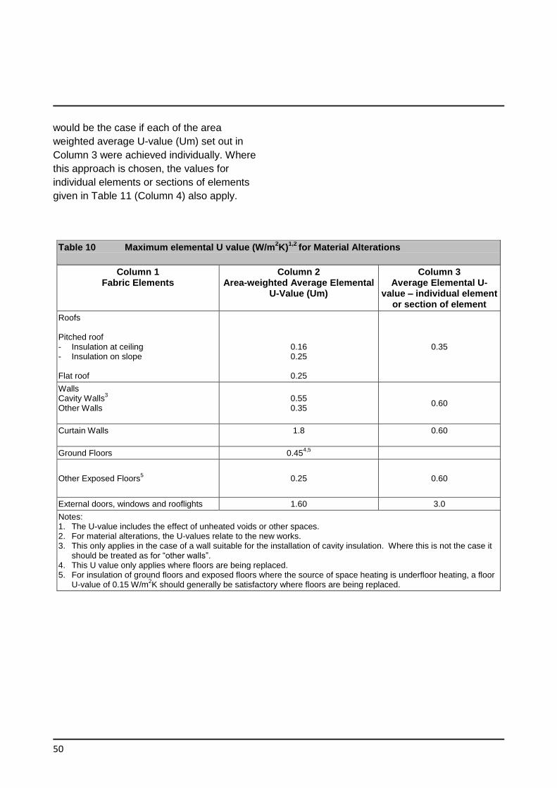
50
would be the case if each of the area
weighted average U-value (Um) set out in
Column 3 were achieved individually. Where
this approach is chosen, the values for
individual elements or sections of elements
given in Table 11 (Column 4) also apply.
Table 10 Maximum elemental U value (W/m2K)
1,2 for Material Alterations
Column 1 Fabric Elements
Column 2 Area-weighted Average Elemental
U-Value (Um)
Column 3 Average Elemental U-
value – individual element or section of element
Roofs Pitched roof - Insulation at ceiling - Insulation on slope Flat roof
0.16 0.25
0.25
0.35
Walls Cavity Walls
3
Other Walls
0.55 0.35
0.60
Curtain Walls
1.8
0.60
Ground Floors 0.454,5
Other Exposed Floors5 0.25 0.60
External doors, windows and rooflights 1.60 3.0
Notes: 1. The U-value includes the effect of unheated voids or other spaces. 2. For material alterations, the U-values relate to the new works. 3. This only applies in the case of a wall suitable for the installation of cavity insulation. Where this is not the case it
should be treated as for “other walls”. 4. This U value only applies where floors are being replaced. 5. For insulation of ground floors and exposed floors where the source of space heating is underfloor heating, a floor
U-value of 0.15 W/m2K should generally be satisfactory where floors are being replaced.
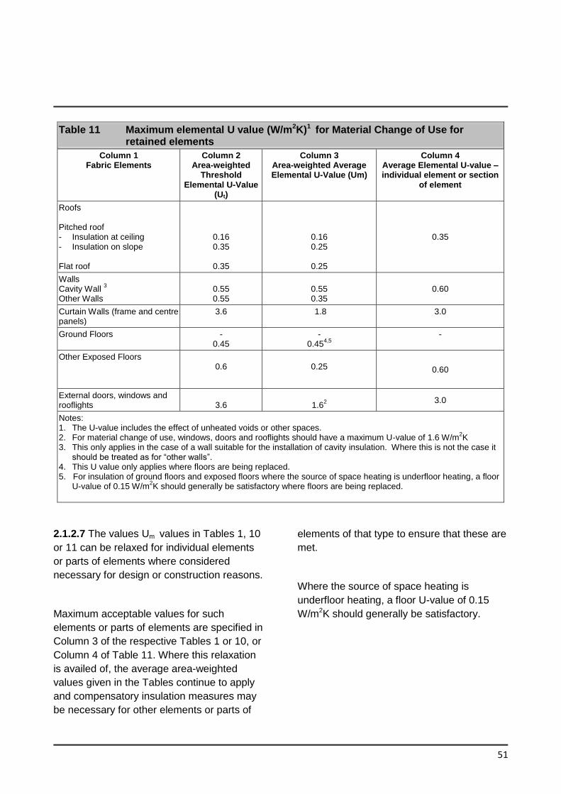
51
Table 11 Maximum elemental U value (W/m2K)1 for Material Change of Use for retained elements
Column 1 Fabric Elements
Column 2 Area-weighted
Threshold Elemental U-Value
(Ut)
Column 3 Area-weighted Average Elemental U-Value (Um)
Column 4 Average Elemental U-value – individual element or section
of element
Roofs Pitched roof - Insulation at ceiling - Insulation on slope Flat roof
0.16 0.35
0.35
0.16 0.25
0.25
0.35
Walls Cavity Wall
3
Other Walls
0.55 0.55
0.55 0.35
0.60
Curtain Walls (frame and centre panels)
3.6
1.8
3.0
Ground Floors - 0.45
- 0.45
4,5 -
Other Exposed Floors 0.6
0.25 0.60
External doors, windows and rooflights
3.6
1.6
2 3.0
Notes: 1. The U-value includes the effect of unheated voids or other spaces. 2. For material change of use, windows, doors and rooflights should have a maximum U-value of 1.6 W/m
2K
3. This only applies in the case of a wall suitable for the installation of cavity insulation. Where this is not the case it should be treated as for “other walls”.
4. This U value only applies where floors are being replaced. 5. For insulation of ground floors and exposed floors where the source of space heating is underfloor heating, a floor
U-value of 0.15 W/m2K should generally be satisfactory where floors are being replaced.
2.1.2.7 The values Um values in Tables 1, 10
or 11 can be relaxed for individual elements
or parts of elements where considered
necessary for design or construction reasons.
Maximum acceptable values for such
elements or parts of elements are specified in
Column 3 of the respective Tables 1 or 10, or
Column 4 of Table 11. Where this relaxation
is availed of, the average area-weighted
values given in the Tables continue to apply
and compensatory insulation measures may
be necessary for other elements or parts of
elements of that type to ensure that these are
met.
Where the source of space heating is
underfloor heating, a floor U-value of 0.15
W/m2K should generally be satisfactory.
52
2.1.3 Thermal bridging
2.1.3.1 To avoid excessive heat losses and
local condensation problems, reasonable
care should be taken to ensure continuity of
insulation and to limit local thermal bridging,
e.g. around windows, doors and other wall
openings, at junctions between elements and
other locations. Any thermal bridge should
not pose a risk of surface or interstitial
condensation. See Appendix D for further
information in relation to thermal bridging and
it’s effect on building heat loss.
2.1.3.2 Reasonable provision with regard to
limitation of thermal bridging for extensions is
to adopt Acceptable Construction Details for
constructions similar to those for dwellings as
shown in the document “Limiting Thermal
Bridging and Air Infiltration – Acceptable
Construction Details” where appropriate (see
Appendix D, Table D1) or other details that
are similar or have been assessed as limiting
thermal bridging to an equivalent level.
2.1.3.3 For material alterations or material
change of use lintel, jamb and cill designs
similar to those shown in Diagram 2 would be
satisfactory.
At lintel, jambs and cills generally a 15 mm
thickness of insulation material having λ-
value of 0.033 W/mK (or equivalent) will
generally be adequate. Where advanced
levels of insulation are applied a higher
thermal resistance may be necessary.
2.1.3.4 For material alterations or material
change of use care should be taken to control
the risk of thermal bridging at the edges of
floors where the floor is being replaced. The
insulation should have minimum thermal
resistance of 0.7 m2K/W (25 mm of insulation
with thermal conductivity of 0.035 W/mK, or
equivalent).
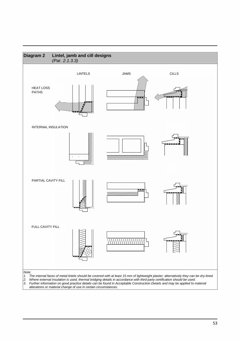
53
Diagram 2 Lintel, jamb and cill designs (Par. 2.1.3.3)
Note: 1. The internal faces of metal lintels should be covered with at least 15 mm of lightweight plaster; alternatively they can be dry-lined. 2. Where external insulation is used, thermal bridging details in accordance with third party certification should be used. 3. Further information on good practice details can be found in Acceptable Construction Details and may be applied to material
alterations or material change of use in certain circumstances.
LINTELS JAMS CILLS
HEAT LOSS
PATHS
INTERNAL INSULATION
PARTIAL CAVITY FILL
FULL CAVITY FILL
54
2.1.4 Air permeability
2.1.4.1 For extensions to existing buildings
reasonable levels of air permeability can be
faciltitated by adopting the standard details
referred to in paragraph 2.1.3.2 above,
together with an appropriate performance
specification and the on-site inspection
regime and related quality control
procedures, referred to in that paragraph.
Alternative approaches to element design,
details and quality control procedures may
also be acceptable, provided it can be shown
that these approaches are equivalent.
2.1.4.2 For material alterations or material
change of use, infiltration of cold outside air
should be limited by reducing unintentional air
paths as far as is practicable. Measures to
ensure this include: -
(a) sealing the void between dry-lining and
masonry walls at the edges of openings
such as windows and doors, and at the
junctions with walls, floors and ceilings
(e.g. by the use of certified air tightness
tapes and/or membranes);
(b) sealing vapour control membranes in
timber-frame constructions;
(c) fitting draught-stripping in the frames of
openable elements of windows, doors
and rooflights;
(d) sealing around loft hatches;
(e) ensuring boxing for concealed services
is sealed at floor and ceiling levels and
sealing piped services where they
penetrate or project into hollow
constructions or voids.
Diagram 3 illustrates some of these
measures. Further information on sealing
services penetrations can also be found in
the Introduction Section of Acceptable
Construction Details and BSRIA BG 47/2013
Designing and Constructing for Airtightness
Care should be taken to ensure compliance
with the ventilation requirements of Part F
and Part J.
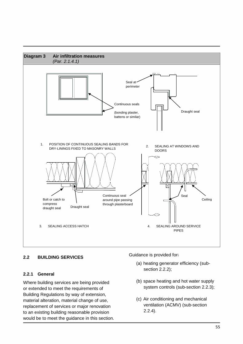
55
Diagram 3 Air infiltration measures (Par. 2.1.4.1)
2.2 BUILDING SERVICES
2.2.1 General
Where building services are being provided
or extended to meet the requirements of
Building Regulations by way of extension,
material alteration, material change of use,
replacement of services or major renovation
to an existing building reasonable provision
would be to meet the guidance in this section.
Guidance is provided for:
(a) heating generator efficiency (sub-
section 2.2.2);
(b) space heating and hot water supply
system controls (sub-section 2.2.3);
(c) Air conditioning and mechanical
ventilation (ACMV) (sub-section
2.2.4).
Ceiling
Seal at
perimeter
Draught seal
Continuous seals
(bonding plaster,
battens or similar)
1. POSITION OF CONTINUOUS SEALING BANDS FOR
DRY-LININGS FIXED TO MASONRY WALLS 2. SEALING AT WINDOWS AND
DOORS
Bolt or catch to
compress
draught seal Draught seal
Continuous seal
around pipe passing
through plasterboard
Seal
s
4. SEALING AROUND SERVICE
PIPES
Ceiling
3. SEALING ACCESS HATCH
56
(d) Air conditioning and mechanical
ventilation (ACMV) controls (sub-
section 2.2.5);
(e) insulation of hot water storage
vessels, pipes and ducts (sub-section
2.2.6);
(f) artificial lighting (sub-section 2.2.7).
2.2.2 Heat Generator Efficiency
Heat generators should be designed and
installed so that they operate efficiently over
the range of loading likely to be encountered.
Minimum energy efficiency standards for heat
generators in existing buildings are provided
in Table 2 for boilers and Par 1.4.1.2 for heat
pumps.
2.2.3 Controls for space heating and hot
water supply systems
2.2.3.1 Space and water heating systems
should be effectively controlled so as to limit
energy use by these systems to that required
to satisfy user requirements and, where
appropriate, to protect the building and it’s
contents from damage due to low
temperatures. This section is not intended to
apply to control systems for specialist or
industrial processes.
2.2.3.2 Buildings should be provided with
zone, timing and temperature controls such
that, for space heating, each functional area
is maintained at the required temperature
only during the period when it is occupied.
Additional space heating controls may be
provided to allow heating during extended
unusual occupation hours and to provide for
sufficient background heating to prevent
condensation or frost damage when the
heating system would otherwise be switched
off.
2.2.3.3 Hot water systems should be
designed and provided with appropriate
controls so that they can be operated
efficiently. For efficient operation, hot water
systems should not be over-sized and should
be designed to avoid low-load operation of
heat generators. The layout should minimize
the length of circulation loops and minimize
the length and diameter of dead legs.
Designers should have particular regard to
the need to limit the risk of promoting the
growth of legionella bacteria. Local
instantaneous heaters should be used, where
appropriate.
2.2.3.4 For buildings with a heat generator
with an effective rated output for space
heating purposes of more than 70kW a full
building management system should be
installed to control the heat generator(s). A
full BMS linked to the heating plant will
provide sequential controls of multiple heat
generators, full zoned time control and
weather compensation where applicable,
frost protection or night set-back optimization
and monitoring and targeting.
Minimum controls for heat generator systems
are specified in Tables 3,4 & 5.
2.2.3.5 For buildings with a heat generator
with an effective rated output for space
heating purposes with an effective rated
output of over 70 kW a building automation
and control system should be installed for the
building with the following functions:
(a) continuously monitoring, analysing
and allowing for adjusting energy
57
usage including that provided by
renewable energy technologies;
(b) benchmarking the building’s energy
efficiency, detecting losses in
efficiency of technical building
systems, and informing the person
responsible for the facilities or
technical building management about
opportunities for energy efficiency
improvement;
(c) allowing communication with
connected technical building systems
and other appliances inside the
building, and being interoperable with
technical building systems across
different types of proprietary
technologies, devices and
manufacturers, and
(d) monitoring the energy provided by
renewable energy technologies.
A building automation and control system and
a building management system may be
integrated into a single system.
2.2.3.6 In larger or more complex buildings,
control systems for boiler systems may follow
the guidance contained in Chapter 5 CIBSE
Guide H: Building Control Systems published
by CIBSE.
2.2.3.7 Where controls and building
management systems are installed they
should be commissioned by competent
persons and commissioning records kept for
handover information.
2.2.4 Air conditioning and mechanical
ventilation (ACMV)
2.2.4.1 Buildings should be designed and
constructed in such a way that:
(a) the form and fabric of the building
minimises the use of mechanical
ventilation or cooling systems for
cooling purposes, and
(b) the ventilating and cooling systems
installed are energy efficient and are
capable of being controlled to achieve
optimum energy efficiency.
2.2.4.2 Natural ventilation strategies should
be considered appropriate for the building
geometry.
Particular attention should be paid to limiting
solar gains by ensuring that areas of the
external building fabric which are susceptible
to solar gain have appropriate areas of solar
shading.
2.2.4.3 A mixed-mode building integrates the
use of air conditioning when and where it is
necessary, with use of natural ventilation
whenever it is feasible or desirable, to
maximise occupant comfort whilst reducing
energy use (compared to 'year round' use of
air conditioning).CIBSE Guide AM 13 Mixed
Mode Ventilation provides guidance on mixed
mode design.
2.2.4.4 Free cooling may be optimised in
order to minimise the need for mechanical
ventilation and air conditioning. When the
external air temperature is higher than the
space temperature the system design should
allow the provision of a minimum level of
58
fresh air. Enthalpy control should also be
considered to improve free cooling. The SEAI
Guide to “Relative Humidity in Data Centres”
explains how free cooling operates in the Irish
Climate. BSRIA guide BG 8/2004 Free
Cooling Systems also provides guidance on
the design of free cooling systems. Where
free cooling is used air-conditioning systems
are still required to have heat recovery
systems as required by Commission
Regulation (EU) 1253/2014 with regard to
eco-design requirements for ventilation units.
2.2.4.5 Buildings that use ACMV systems
should be designed and constructed such
that:
(a) the form and fabric of the building do
not result in a requirement for excessive
installed capacity of ACMV equipment. In
particular, the suitable specification of
glazing ratios and solar shading are an
important way to limit cooling requirements;
(b) components such as fans, pumps and
refrigeration equipment are reasonably
efficient and appropriately sized so as to
have no more capacity for demand and
standby than is necessary for the task;
(c) suitable facilities are provided to
manage, control and monitor the operation
of the equipment and the systems.
2.2.4.6 The specific fan power of air distribution systems at the design flow rate should be no worse than in Table 12. Specific fan power is a function of the system resistance that the fan has to overcome to provide the required flowrate. I.S. EN 13779 Table A8 provides guidance on system pressure drop. To minimize specific fan power it is recommended that the low range is used as a design target.
Where the primary air and cooling is provided by central plant and by an air distribution system that includes the additional components listed in Table 12a, the allowed specific fan powers may be increased by each of the values shown in Table 12a to account for the additional resistance.
2.2.4.7 Ventilation fans driven by electric
motors should comply with European
Commission Regulation No. 327/2011
implementing Directive 2009/125/EC with
regard to eco-design requirements for fans
driven by motors with an electric input power
between 125W and 500 kW.
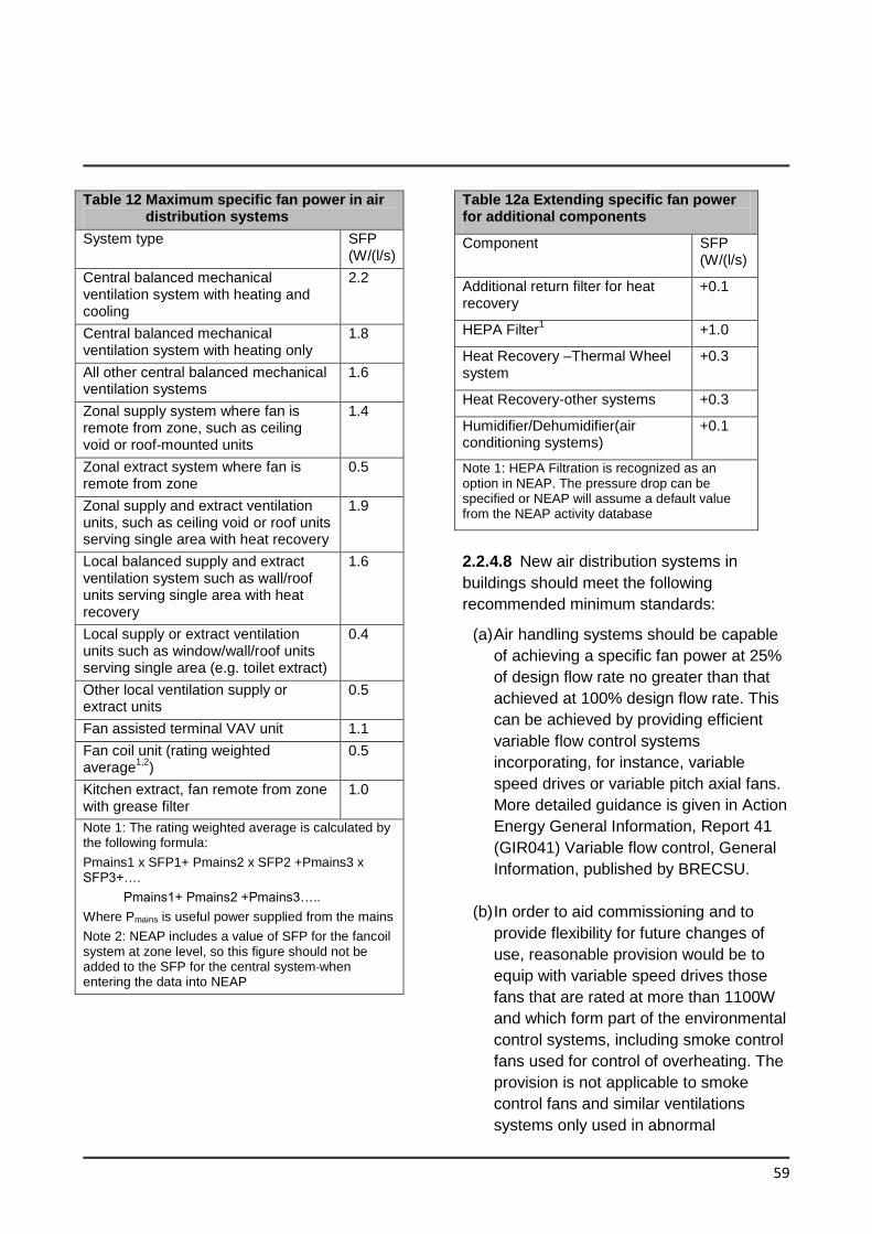
59
Table 12 Maximum specific fan power in air distribution systems
System type SFP (W/(l/s)
Central balanced mechanical ventilation system with heating and cooling
2.2
Central balanced mechanical ventilation system with heating only
1.8
All other central balanced mechanical ventilation systems
1.6
Zonal supply system where fan is remote from zone, such as ceiling void or roof-mounted units
1.4
Zonal extract system where fan is remote from zone
0.5
Zonal supply and extract ventilation units, such as ceiling void or roof units serving single area with heat recovery
1.9
Local balanced supply and extract ventilation system such as wall/roof units serving single area with heat recovery
1.6
Local supply or extract ventilation units such as window/wall/roof units serving single area (e.g. toilet extract)
0.4
Other local ventilation supply or extract units
0.5
Fan assisted terminal VAV unit 1.1
Fan coil unit (rating weighted average
1,2)
0.5
Kitchen extract, fan remote from zone with grease filter
1.0
Note 1: The rating weighted average is calculated by the following formula:
Pmains1 x SFP1+ Pmains2 x SFP2 +Pmains3 x SFP3+….
Pmains1+ Pmains2 +Pmains3…..
Where Pmains is useful power supplied from the mains
Note 2: NEAP includes a value of SFP for the fancoil system at zone level, so this figure should not be added to the SFP for the central system when entering the data into NEAP
Table 12a Extending specific fan power for additional components
Component SFP (W/(l/s)
Additional return filter for heat recovery
+0.1
HEPA Filter1 +1.0
Heat Recovery –Thermal Wheel system
+0.3
Heat Recovery-other systems +0.3
Humidifier/Dehumidifier(air conditioning systems)
+0.1
Note 1: HEPA Filtration is recognized as an option in NEAP. The pressure drop can be specified or NEAP will assume a default value from the NEAP activity database
2.2.4.8 New air distribution systems in
buildings should meet the following
recommended minimum standards:
(a) Air handling systems should be capable
of achieving a specific fan power at 25%
of design flow rate no greater than that
achieved at 100% design flow rate. This
can be achieved by providing efficient
variable flow control systems
incorporating, for instance, variable
speed drives or variable pitch axial fans.
More detailed guidance is given in Action
Energy General Information, Report 41
(GIR041) Variable flow control, General
Information, published by BRECSU.
(b) In order to aid commissioning and to
provide flexibility for future changes of
use, reasonable provision would be to
equip with variable speed drives those
fans that are rated at more than 1100W
and which form part of the environmental
control systems, including smoke control
fans used for control of overheating. The
provision is not applicable to smoke
control fans and similar ventilations
systems only used in abnormal
60
circumstances.
2.2.4.9 In order to limit air leakage,
ventilation ductwork should be made and
assembled so as to be reasonably airtight.
This may be achieved by following the
guidance in EN Standards I.S. EN1507:2006,
I.S. EN12237:2003 and I.S. EN 13403:2003
In order to limit air leakage air handling units
should be made and assembled so as to be
reasonably airtight. This may be
demonstrated by achieving Class L2 air
leakage as given in I.S. EN 1886 2007.
2.2.4.10 The minimum seasonal space cooling energy efficiency of cooling products should be as provided for in the Eco-design Regulations. The relevant Eco-design Regulations are:-
- Commission Regulation (EU) 2016/2281 for the setting of eco-design requirements for energy-related products, with regard to eco-design requirements for air heating products, cooling products, high temperature
process chillers and fan coil units.
- -Commission Regulation (EU) No
206/2012 with regard to eco-design
requirements for air conditioners and
comfort fans.
2.2.5 ACMV Controls
2.2.5.1 Systems should be provided with
appropriate controls to enable the
achievement of reasonable standards of
energy efficiency in use, in normal
circumstances, the following features would
be appropriate for heating, ventilation and air-
conditioning systems and controls
(a) The systems should be divided into
separate control zones to correspond to
each area of the building that has a
significantly different solar exposure or
type of use; and
(b) Each separate control zone should be
capable of independent timing and
temperature control and, where
appropriate, ventilation and air
recirculation rate; and
(c) The provision of the service should
respond to the requirements of the
space it serves. If both heating and
cooling are provided they should be
controlled so as not to operate
simultaneously unless required for
humidification control.
(d) Central plant should only operate as
and when the zone systems require it.
The default condition should be off.
(e) In addition to these general control
provisions the systems should meet
general control and efficiency standards
as set out in Par 2.2.5.2
2.2.5.2 A minimum controls package should
be provided as in Table 7
2.2.5.3 For buildings with a with an effective
rated output for air-conditioning systems of
over 70 kW a building automation and control
system should be installed for the building
with the following functions:
61
(a) continuously monitoring, analysing and
allowing for adjusting energy usage;
(b) benchmarking the building’s energy
efficiency, detecting losses in
efficiency of technical building
systems, and informing the person
responsible for the facilities or
technical building management about
opportunities for energy efficiency
improvement;
(c) allowing communication with
connected technical building systems
and other appliances inside the
building, and being interoperable with
technical building systems across
different types of proprietary
technologies, devices and
manufacturers and
(d) monitoring the energy provided by
renewable energy technologies.
A building automation and control system and
a building management system may be
integrated into a single system.
2.2.5.4 Where controls and building
management systems are installed they
should be commissioned by competent
persons and commissioning records kept for
handover information.
2.2.6 Insulation of storage vessels, pipes
and ducts
2.2.6.1 This section only applies to pipes,
ducts and vessels for the provision of space
heating, space cooling (including chilled
water and refrigerant pipe work) and hot
water supply for normal occupation. It does
not apply to pipes, ducts and vessels
associated with specialist or industrial
processes.
2.2.6.2 Hot water storage vessels, pipes and
ducts associated with the provision of heating
and hot water in a building should be
insulated to limit heat loss, except where the
heat flow through the wall of the pipe, duct or
vessel is always useful in conditioning the
surrounding space. Storage vessels for
chilled water and refrigerant, and pipes and
ducts that serve air-conditioning systems
should be insulated to limit heat gain from the
surrounding environment.
2.2.6.3 Provision of insulation to pipes, ducts
and storage vessels, in accordance with the
standards specified in BS 5422: 2009, should
adequately limit heat loss or heat gain, as
appropriate. The appropriate insulation level
for storage vessels should be taken as that
given in BS 5422: 2009 for flat surfaces.
2.2.6.4 It should be noted that water pipes
and storage vessels in unheated areas will
generally need to be insulated for the
purpose of protection against freezing.
Guidance on suitable protection measures is
given in Technical Guidance Document G
and BRE Report 262, Thermal insulation:
avoiding risks published by BRE.
2.2.7 Artificial lighting
2.2.7.1 This Section provides guidance for the following types of lighting:
• general interior lighting
62
• display lighting
2.2.7.2 For the purposes of this section the definitions for lighting are provided in Appendix F.
2.2.7.3 General purpose artificial lighting systems shall be designed and controlled so as to ensure the efficient use of energy for this purpose.
2.2.7.4 The aim of lighting controls should be to encourage the maximum use of daylight and to avoid unnecessary artificial lighting, particularly when spaces are unoccupied, having regard to the need to ensure that the operation of automatically switched lighting systems does not endanger occupants in a building. BS 8206: Part 2: 2008 Code of Practice for daylight and CIBSE Lighting Guide LG 10 gives advice on adequate daylight provision.
2.2.7.5 Lighting controls in buildings should follow the guidance in BRE Digest 498 Selecting Lighting Controls. Display lighting where provided should be controlled on dedicated circuits that can be switched off when not required.
Adequate control depends on the nature and use pattern of the building. This may be achieved by one, or more, of the following means, used alone or in combination, as appropriate. Detailed guidance on the application of the following methods is provided in Table 2 of BRE Digest 498 Selecting Lighting Controls.
(a) local manually operated switches in easily accessible positions within each working area or at boundaries between working areas and general circulation routes. The distance on plan from any local switch to the luminaries it controls should generally be not more than 6m, or twice the height of the light fitting above the floor if this is greater;
(b) daylight-linked photo-electric switching or dimming for lighting adjacent to windows or other sources of natural light;
(c) remote controlled switches operated by infrared transmitter, sonic, ultrasonic or telephone handset controls;
(d) automatic switching systems which switch the lighting off when they sense the absence of occupants;
(e) time-controlled switches.
All the above types of control can form part of a lighting or building energy management system. These enable a range of additional functions including remote operation and management of lighting systems. 2.2.7.6 Lighting in existing buildings should meet the minimum standards for:
(i) efficacy (averaged over the whole area of the applicable type of space in the building) and controls in column 3 of Table 8
OR
(ii) maximum Lighting Energy Numeric Indicator (LENI) (kWh/m2/year) listed in Table 9. LENI is based on BS EN 15193:2007 Energy Performance of Buildings - Energy Requirements for Lighting. The LENI should be calculated using the procedure in Appendix F to meet the maximum values in Table 9
63
2.3 Major Renovation
2.3.1 Where more than 25% of the surface area of the building envelope undergoes renovation the energy performance of the whole building should be improved to Cost Optimal level in so far as this is technically, functionally and economically feasible.
2.3.2 When calculating the proportion of surface area undergoing renovation the area of the whole building external envelope should be taken into account including i.e. external walls, roofs, floors, windows, doors , and roof windows and lights
Works to the surface area of the building include the following:
- Cladding the external surface of the element
- Drylining the internal surface of an element
- Replacing windows
- Stripping down the element to expose the basic structural components (brickwork/blockwork, timberframe steelframe, joists, rafters, purlins etc.) and then rebuilding to achieve all the necessary performance requirements. Painting, replastering or rendering are not considered a major renovation for this part of the regulation.
2.3.3 When undertaking on or in connection with a building that is of architectural or historical interest the aim should be to improve the building as far as is reasonably practical. The work should not prejudice the character of the building or increase the risk of long term deterioration of the building fabric or fittings. Refer to Par 0.5.
2.3.4 The following improvements are normally considered to be cost optimal and
will typically be economically feasible when more than 25% of the surface area of a building is being upgraded:
Upgrading oil, gas or biomass heating systems more than 15 years old and with an efficiency of less than that shown in Table 2;
Upgrading controls for direct electric space heating systems to achieve the level of controls described in Table 5;
Upgrading cooling and ventilation systems more than 15 years old and a cooling unit Seasonal Energy Efficiency Ratio less than that in the Eco-design Regulations referenced in par 1.4.3.11 and/or Specific Fan Power greater than that in Table 12 and by the provision of new plant; and
Upgrading general lighting systems that are more than 15 years old or have an average lamp efficacy of less than 40 lamp-lumens per circuit-watt as defined in NEAP and that serves greater than 100m2 to the guidance in section 2.2.7.
2.3.5 As an alternative to the measures in paragraph 2.3.4 where the whole building performance achieves the primary energy performance levels as calculated in NEAP and specified in Table 13 where technically , functionally and economically feasible this can be considered the cost optimal level of performance. To allow flexibility in application the values in Table 13 can be increased by 15%.
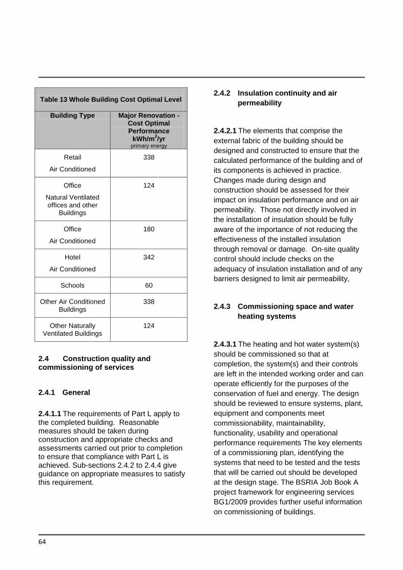
64
2.4 Construction quality and commissioning of services
2.4.1 General
2.4.1.1 The requirements of Part L apply to the completed building. Reasonable measures should be taken during construction and appropriate checks and assessments carried out prior to completion to ensure that compliance with Part L is achieved. Sub-sections 2.4.2 to 2.4.4 give guidance on appropriate measures to satisfy this requirement.
2.4.2 Insulation continuity and air
permeability
2.4.2.1 The elements that comprise the
external fabric of the building should be
designed and constructed to ensure that the
calculated performance of the building and of
its components is achieved in practice.
Changes made during design and
construction should be assessed for their
impact on insulation performance and on air
permeability. Those not directly involved in
the installation of insulation should be fully
aware of the importance of not reducing the
effectiveness of the installed insulation
through removal or damage. On-site quality
control should include checks on the
adequacy of insulation installation and of any
barriers designed to limit air permeability,
2.4.3 Commissioning space and water
heating systems
2.4.3.1 The heating and hot water system(s)
should be commissioned so that at
completion, the system(s) and their controls
are left in the intended working order and can
operate efficiently for the purposes of the
conservation of fuel and energy. The design
should be reviewed to ensure systems, plant,
equipment and components meet
commissionability, maintainability,
functionality, usability and operational
performance requirements The key elements
of a commissioning plan, identifying the
systems that need to be tested and the tests
that will be carried out should be developed
at the design stage. The BSRIA Job Book A
project framework for engineering services
BG1/2009 provides further useful information
on commissioning of buildings.
Table 13 Whole Building Cost Optimal Level
Building Type Major Renovation - Cost Optimal Performance
kWh/m2/yr
primary energy
Retail
Air Conditioned
338
Office
Natural Ventilated offices and other
Buildings
124
Office
Air Conditioned
180
Hotel
Air Conditioned
342
Schools 60
Other Air Conditioned Buildings
338
Other Naturally Ventilated Buildings
124
65
2.4.4 Air Leakage Testing of Ductwork
2.4.4.1 Where new systems are installed
ductwork leakage testing should be carried
out on Class C and Class D ductwork where
required by and in accordance with the
procedures set out in B&ES DW/143 and
B&ES DW/144 on systems served by fans
with a design flow greater than 1m3/s.
If ductwork fails to meet the leakage
standard, remedial work should be carried out
as necessary to achieve satisfactory
performance in retests and further ductwork
sections should be tested as set out in
DW/143
2.5 User information
2.5.1 General
For replacement of services and major
renovations the owner or occupants of the
building should be provided with sufficient
information about the building, the fixed
building services and their maintenance
requirements so that the building can be
operated in such a manner as to use no more
fuel and energy than is reasonable in the
circumstances. A way of complying would be
to provide a suitable set of operating and
maintenance instructions aimed at achieving
economy in the use of fuel and energy in a
way that the building owner or occupants can
understand. The instructions should be
directly related to the particular system(s)
installed in the building. Without prejudice to
the need to comply with health and safety
requirements, the instructions should explain
to the building owner or occupier of the
building how to operate the system(s)
efficiently. This should include:-
(a) Drawings and manuals necessary to
operate and maintain the energy using
equipment in the buildings e.g. boilers,
chillers, pumps and fans, lighting,
building management systems
(b) the monitoring of energy use making of
adjustments to the control settings for
energy using equipment; and
(c) what routine maintenance is needed to
enable operating efficiency to be
maintained at a reasonable level
through the service life(lives) of the
system(s).
66
APPENDICES
Appendix A Calculation of U-Values
67
GENERAL
A1.1 General guidance on the calculation
of U-values is contained in Report BR 443
“Conventions for the Calculation of U-values”
2006. For building elements and components
generally, the method of calculating U-values
is specified in I.S. EN ISO 6946: 2007. U-
values of components involving heat transfer
to the ground, e.g. ground floors with or
without floor voids, basement walls, are
calculated by the method specified in I.S. EN
ISO 13370: 2007. A soil thermal conductivity
of 2.0 W/mK should be used, unless
otherwise verified. U-values for windows,
doors and shutters may be calculated using
I.S. EN ISO 10077-1: 2006 or I.S. EN ISO
10077-2: 2012. U Values for curtain walling
should be calculated using I.S. EN
12631:2012. Information on U-values and
guidance on calculation procedures
contained in the 2015 8th edition of CIBSE
Guide Section A3: Thermal Properties of
Building Structures are based on these
standards.
A method for assessing U-values of light
steelframed constructions is given in Digest
465 “U-values for light steel construction”,
published by BRE IP 10/02 “Metal cladding:
assessing thermal performance of built-up
systems which use ‘Z’ spacers” published by
BRE.
Software packages to perform U-value
calculations in accordance with the standards
above are readily available.
A1.2 U-values derived by calculation
should be rounded to two significant figures
and relevant information on input data should
be provided. When calculating U-values the
effects of timber joists, structural and other
framing, mortar bedding, window frames and
other small areas where thermal bridging
occurs must be taken into account. Similarly,
account must be taken of the effect of small
areas where the insulation level is reduced
significantly relative to the general level for
the component or structure element under
consideration. Thermal bridging may be
disregarded, however, where the general
thermal resistance does not exceed that in
the bridged area by more than 0.1 m2K/W.
For example, normal mortar joints need not
be taken into account in calculations for
brickwork or concrete blockwork where the
density of the brick or block material is in
excess of 1500 kg/m3. A ventilation opening
in a wall or roof (other than a window,
rooflight or door opening), may be considered
as having the same U-value as the element in
which it occurs.
A1.3 Examples of the application of the
calculation method specified in I.S. EN 6946:
2007 are given below. An example of the
calculation of ground floor U-values using I.S.
EN ISO 13370: 2007 is also given.
A1.4 Thermal conductivities of common
building materials are given in Table A1. For
the most part, these are taken from I.S. EN
ISO 10456: 2007 or CIBSE Guide Section
A3. Values for common insulation materials
are also available in these documents. See
paragraph 0.3.3 regarding application of
these Tables.
SIMPLE STRUCTURE WITHOUT THERMAL
BRIDGING
A2.1 To calculate the U-value of a building
element (wall or roof) using I.S. EN ISO 6946:
68
2007, the thermal resistance of each
component is calculated, and these thermal
resistances, together with surface resistances
as appropriate, are then combined to yield
the total thermal resistance and U-value. The
result is corrected to account for mechanical
fixings (e.g. wall ties) or air gaps if required.
For an element consisting of homogenous
layers with no thermal bridging, the total
resistance is simply the sum of individual
thermal resistances and surface resistances.
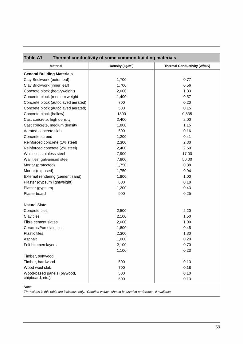
69
Table A1 Thermal conductivity of some common building materials
Material Density (kg/m3) Thermal Conductivity (W/mK)
General Building Materials
Clay Brickwork (outer leaf)
Clay Brickwork (inner leaf)
Concrete block (heavyweight)
Concrete block (medium weight
Concrete block (autoclaved aerated)
Concrete block (autoclaved aerated)
Concrete block (hollow)
Cast concrete, high density
Cast concrete, medium density
Aerated concrete slab
Concrete screed
Reinforced concrete (1% steel)
Reinforced concrete (2% steel)
Wall ties, stainless steel
Wall ties, galvanised steel
Mortar (protected)
Mortar (exposed)
External rendering (cement sand)
Plaster (gypsum lightweight)
Plaster (gypsum)
Plasterboard
Natural Slate
Concrete tiles
Clay tiles
Fibre cement slates
Ceramic/Porcelain tiles
Plastic tiles
Asphalt
Felt bitumen layers
Timber, softwood
Timber, hardwood
Wood wool slab
Wood-based panels (plywood, chipboard, etc.)
1,700
1,700
2,000
1,400
700
500
1800
2,400
1,800
500
1,200
2,300
2,400
7,900
7,800
1,750
1,750
1,800
600
1,200
900
2,500
2,100
2,000
1,800
2,300
1,000
2,100
1,100
500
700
500
500
0.77
0.56
1.33
0.57
0.20
0.15
0.835
2.00
1.15
0.16
0.41
2.30
2.50
17.00
50.00
0.88
0.94
1.00
0.18
0.43
0.25
2.20
1.50
1.00
0.45
1.30
0.20
0.70
0.23
0.13
0.18
0.10
0.13
Note:
The values in this table are indicative only. Certified values, should be used in preference, if available.
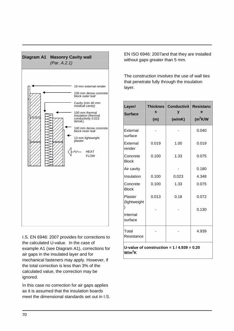
70
I.S. EN 6946: 2007 provides for corrections to
the calculated U-value. In the case of
example A1 (see Diagram A1), corrections for
air gaps in the insulated layer and for
mechanical fasteners may apply. However, if
the total correction is less than 3% of the
calculated value, the correction may be
ignored.
In this case no correction for air gaps applies
as it is assumed that the insulation boards
meet the dimensional standards set out in I.S.
EN ISO 6946: 2007and that they are installed
without gaps greater than 5 mm.
The construction involves the use of wall ties
that penetrate fully through the insulation
layer.
Layer/
Surface
Thicknes
s
(m)
Conductivit
y
(w/mK)
Resistanc
e
(m2K/W
External
surface
External
render
Concrete
Block
Air cavity
Insulation
Concrete
Block
Plaster
(lightweight
)
Internal
surface
-
0.019
0.100
0.100
0.100
0.013
-
-
1.00
1.33
-
0.023
1.33
0.18
-
0.040
0.019
0.075
0.180
4.348
0.075
0.072
0.130
Total
Resistance
- - 4.939
U-value of construction = 1 / 4.939 = 0.20
W/m2K
Diagram A1 Masonry Cavity wall
(Par. A.2.1)
19 mm external render
100 mm dense concrete block outer leaf
Cavity (min 40 mm residual cavity)
100 mm thermal insulation (thermal conductivity 0.023 W/mK)
100 mm dense concrete block inner leaf
13 mm lightweight plaster
HEAT
FLOW
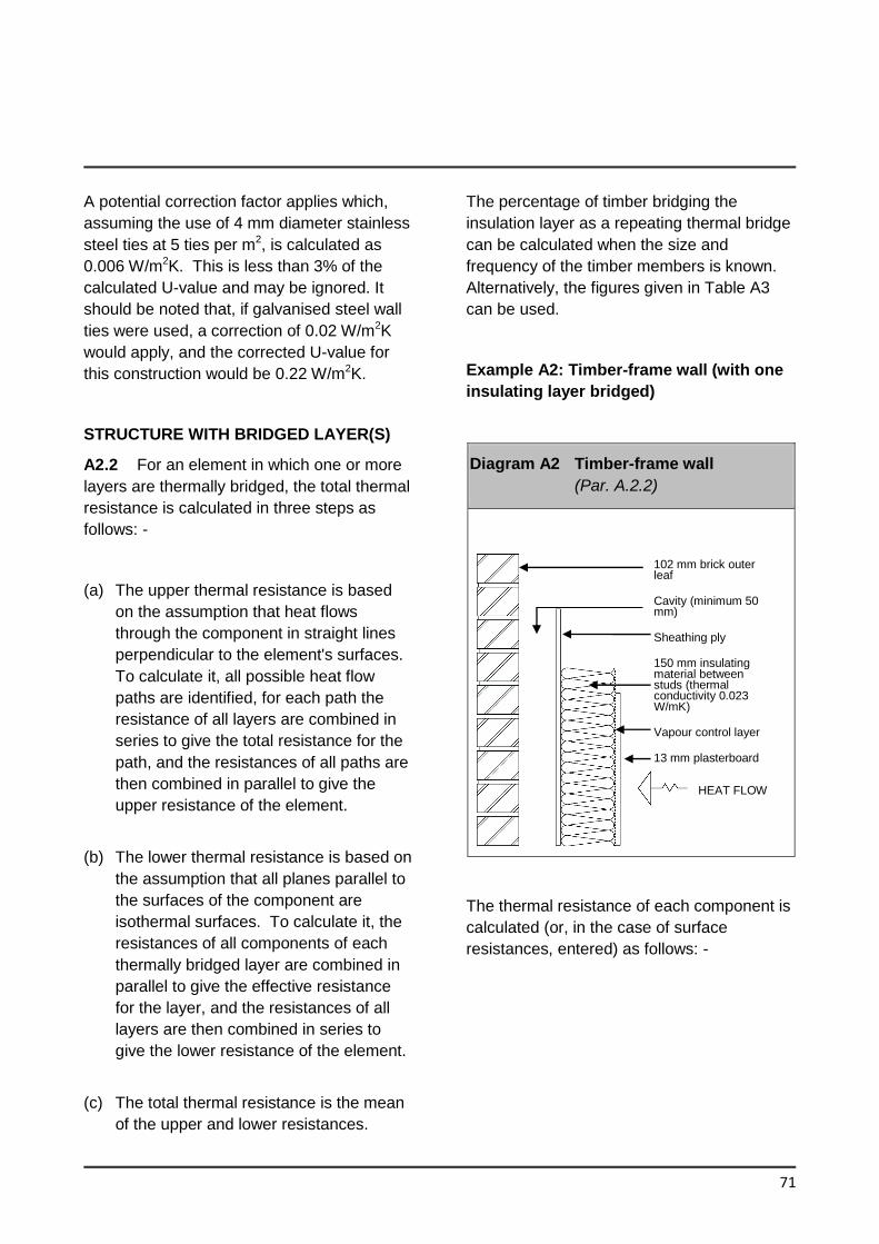
71
A potential correction factor applies which,
assuming the use of 4 mm diameter stainless
steel ties at 5 ties per m2, is calculated as
0.006 W/m2K. This is less than 3% of the
calculated U-value and may be ignored. It
should be noted that, if galvanised steel wall
ties were used, a correction of 0.02 W/m2K
would apply, and the corrected U-value for
this construction would be 0.22 W/m2K.
STRUCTURE WITH BRIDGED LAYER(S)
A2.2 For an element in which one or more
layers are thermally bridged, the total thermal
resistance is calculated in three steps as
follows: -
(a) The upper thermal resistance is based
on the assumption that heat flows
through the component in straight lines
perpendicular to the element's surfaces.
To calculate it, all possible heat flow
paths are identified, for each path the
resistance of all layers are combined in
series to give the total resistance for the
path, and the resistances of all paths are
then combined in parallel to give the
upper resistance of the element.
(b) The lower thermal resistance is based on
the assumption that all planes parallel to
the surfaces of the component are
isothermal surfaces. To calculate it, the
resistances of all components of each
thermally bridged layer are combined in
parallel to give the effective resistance
for the layer, and the resistances of all
layers are then combined in series to
give the lower resistance of the element.
(c) The total thermal resistance is the mean
of the upper and lower resistances.
The percentage of timber bridging the
insulation layer as a repeating thermal bridge
can be calculated when the size and
frequency of the timber members is known.
Alternatively, the figures given in Table A3
can be used.
Example A2: Timber-frame wall (with one
insulating layer bridged)
Diagram A2 Timber-frame wall
(Par. A.2.2)
The thermal resistance of each component is
calculated (or, in the case of surface
resistances, entered) as follows: -
102 mm brick outer leaf
Cavity (minimum 50 mm)
Sheathing ply
150 mm insulating material between studs (thermal conductivity 0.023 W/mK)
Vapour control layer
13 mm plasterboard
HEAT FLOW
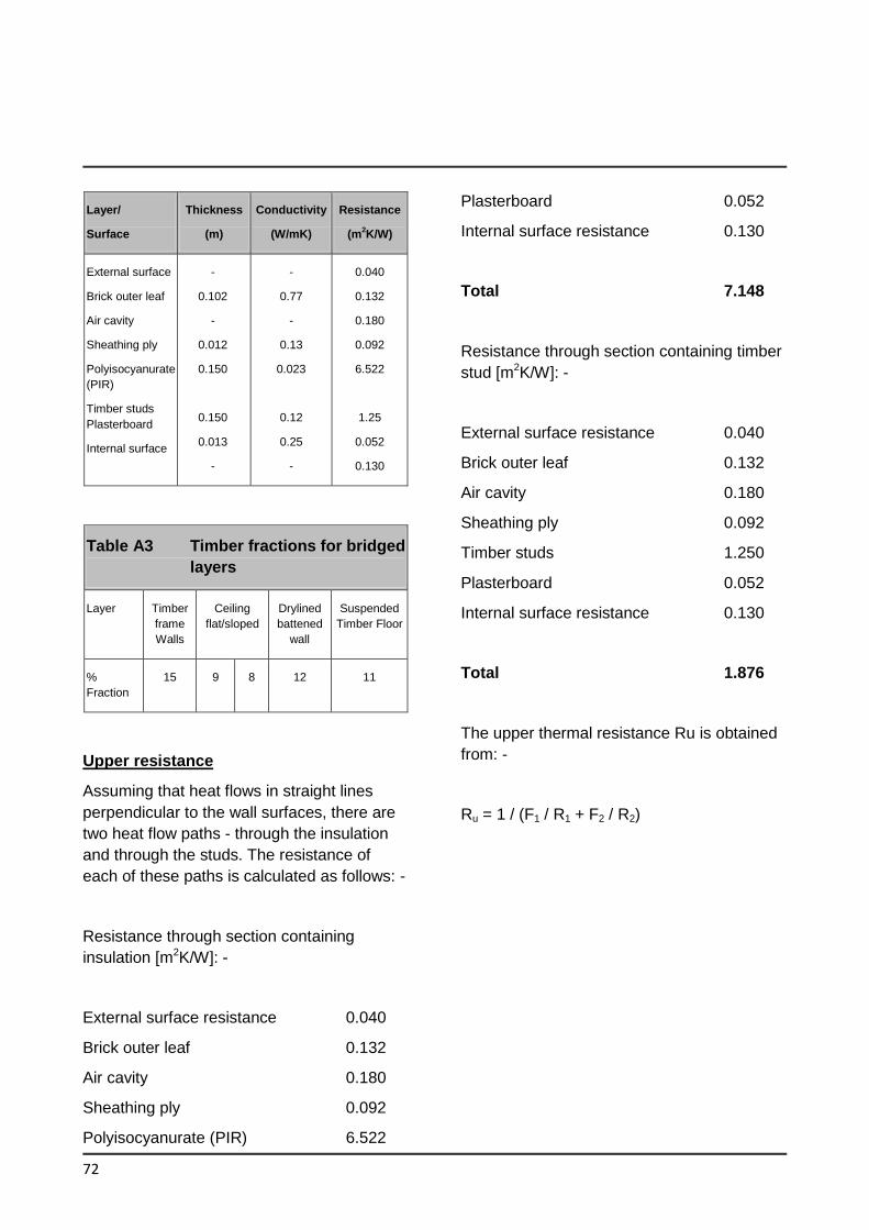
72
Layer/
Surface
Thickness
(m)
Conductivity
(W/mK)
Resistance
(m2K/W)
External surface
Brick outer leaf
Air cavity
Sheathing ply
Polyisocyanurate
(PIR)
Timber studs
Plasterboard
Internal surface
-
0.102
-
0.012
0.150
0.150
0.013
-
-
0.77
-
0.13
0.023
0.12
0.25
-
0.040
0.132
0.180
0.092
6.522
1.25
0.052
0.130
Table A3 Timber fractions for bridged
layers
Layer Timber
frame
Walls
Ceiling
flat/sloped
Drylined
battened
wall
Suspended
Timber Floor
%
Fraction
15 9 8 12 11
Upper resistance
Assuming that heat flows in straight lines
perpendicular to the wall surfaces, there are
two heat flow paths - through the insulation
and through the studs. The resistance of
each of these paths is calculated as follows: -
Resistance through section containing
insulation [m2K/W]: -
External surface resistance 0.040
Brick outer leaf 0.132
Air cavity 0.180
Sheathing ply 0.092
Polyisocyanurate (PIR) 6.522
Plasterboard 0.052
Internal surface resistance 0.130
Total 7.148
Resistance through section containing timber
stud [m2K/W]: -
External surface resistance 0.040
Brick outer leaf 0.132
Air cavity 0.180
Sheathing ply 0.092
Timber studs 1.250
Plasterboard 0.052
Internal surface resistance 0.130
Total 1.876
The upper thermal resistance Ru is obtained
from: -
Ru = 1 / (F1 / R1 + F2 / R2)
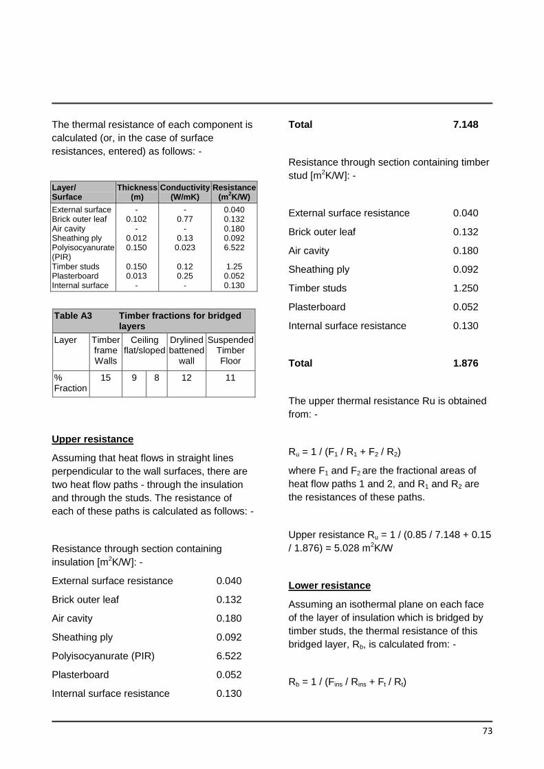
73
The thermal resistance of each component is
calculated (or, in the case of surface
resistances, entered) as follows: -
Layer/ Surface
Thickness (m)
Conductivity (W/mK)
Resistance (m
2K/W)
External surface Brick outer leaf Air cavity Sheathing ply Polyisocyanurate (PIR) Timber studs Plasterboard Internal surface
- 0.102
- 0.012 0.150
0.150 0.013
-
- 0.77
- 0.13
0.023
0.12 0.25
-
0.040 0.132 0.180 0.092 6.522
1.25
0.052 0.130
Table A3 Timber fractions for bridged layers
Layer Timber frame Walls
Ceiling flat/sloped
Drylined battened
wall
Suspended Timber Floor
% Fraction
15 9 8 12 11
Upper resistance
Assuming that heat flows in straight lines
perpendicular to the wall surfaces, there are
two heat flow paths - through the insulation
and through the studs. The resistance of
each of these paths is calculated as follows: -
Resistance through section containing
insulation [m2K/W]: -
External surface resistance 0.040
Brick outer leaf 0.132
Air cavity 0.180
Sheathing ply 0.092
Polyisocyanurate (PIR) 6.522
Plasterboard 0.052
Internal surface resistance 0.130
Total 7.148
Resistance through section containing timber
stud [m2K/W]: -
External surface resistance 0.040
Brick outer leaf 0.132
Air cavity 0.180
Sheathing ply 0.092
Timber studs 1.250
Plasterboard 0.052
Internal surface resistance 0.130
Total 1.876
The upper thermal resistance Ru is obtained
from: -
Ru = 1 / (F1 / R1 + F2 / R2)
where F1 and F2 are the fractional areas of
heat flow paths 1 and 2, and R1 and R2 are
the resistances of these paths.
Upper resistance Ru = 1 / (0.85 / 7.148 + 0.15
/ 1.876) = 5.028 m2K/W
Lower resistance
Assuming an isothermal plane on each face
of the layer of insulation which is bridged by
timber studs, the thermal resistance of this
bridged layer, Rb, is calculated from: -
Rb = 1 / (Fins / Rins + Ft / Rt)
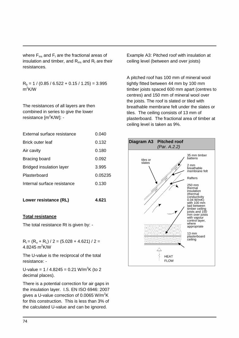
74
where Fins and Ft are the fractional areas of
insulation and timber, and Rins and Rt are their
resistances.
Rb = 1 / (0.85 / 6.522 + 0.15 / 1.25) = 3.995
m2K/W
The resistances of all layers are then
combined in series to give the lower
resistance [m2K/W]: -
External surface resistance 0.040
Brick outer leaf 0.132
Air cavity 0.180
Bracing board 0.092
Bridged insulation layer 3.995
Plasterboard 0.05235
Internal surface resistance 0.130
Lower resistance (RL) 4.621
Total resistance
The total resistance Rt is given by: -
Rt = (Ru + RL) / 2 = (5.028 + 4.621) / 2 =
4.8245 m2K/W
The U-value is the reciprocal of the total
resistance: -
U-value = 1 / 4.8245 = 0.21 W/m2K (to 2
decimal places).
There is a potential correction for air gaps in
the insulation layer. I.S. EN ISO 6946: 2007
gives a U-value correction of 0.0065 W/m2K
for this construction. This is less than 3% of
the calculated U-value and can be ignored.
Example A3: Pitched roof with insulation at
ceiling level (between and over joists)
A pitched roof has 100 mm of mineral wool
tightly fitted between 44 mm by 100 mm
timber joists spaced 600 mm apart (centres to
centres) and 150 mm of mineral wool over
the joists. The roof is slated or tiled with
breathable membrane felt under the slates or
tiles. The ceiling consists of 13 mm of
plasterboard. The fractional area of timber at
ceiling level is taken as 9%.
Diagram A3 Pitched roof (Par. A.2.2)
35 mm timber battens
2 mm breathable membrane felt
Rafters
250 mm thermal insulation (thermal conductivity 0.04 W/mK) with 100 mm laid between timber ceiling joists and 150 mm over joists with vapour control layer, where appropriate
13 mm plasterboard ceiling
tiles or slates
HEAT
FLOW
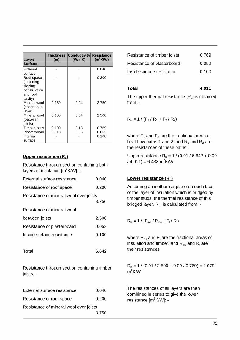
75
Layer/ Surface
Thickness (m)
Conductivity (W/mK)
Resistance (m
2K/W)
External surface Roof space (including sloping construction and roof cavity) Mineral wool (continuous layer) Mineral wool (between joists) Timber joists Plasterboard Internal surface
- -
0.150
0.100
0.100 0.013
-
- -
0.04
0.04
0.13 0.25
-
0.040
0.200
3.750
2.500
0.769 0.052 0.100
Upper resistance (Ru)
Resistance through section containing both
layers of insulation [m2K/W]: -
External surface resistance 0.040
Resistance of roof space 0.200
Resistance of mineral wool over joists
3.750
Resistance of mineral wool
between joists 2.500
Resistance of plasterboard 0.052
Inside surface resistance 0.100
Total 6.642
Resistance through section containing timber
joists: -
External surface resistance 0.040
Resistance of roof space 0.200
Resistance of mineral wool over joists
3.750
Resistance of timber joists 0.769
Resistance of plasterboard 0.052
Inside surface resistance 0.100
Total 4.911
The upper thermal resistance [Ru] is obtained
from: -
Ru = 1 / (F1 / R1 + F2 / R2)
where F1 and F2 are the fractional areas of
heat flow paths 1 and 2, and R1 and R2 are
the resistances of these paths.
Upper resistance Ru = 1 / (0.91 / 6.642 + 0.09
/ 4.911) = 6.438 m2K/W
Lower resistance (RL)
Assuming an isothermal plane on each face
of the layer of insulation which is bridged by
timber studs, the thermal resistance of this
bridged layer, Rb, is calculated from: -
Rb = 1 / (Fins / Rins + Ft / Rt)
where Fins and Ft are the fractional areas of
insulation and timber, and Rins and Rt are
their resistances
Rb = 1 / (0.91 / 2.500 + 0.09 / 0.769) = 2.079
m2K/W
The resistances of all layers are then
combined in series to give the lower
resistance [m2K/W]: -
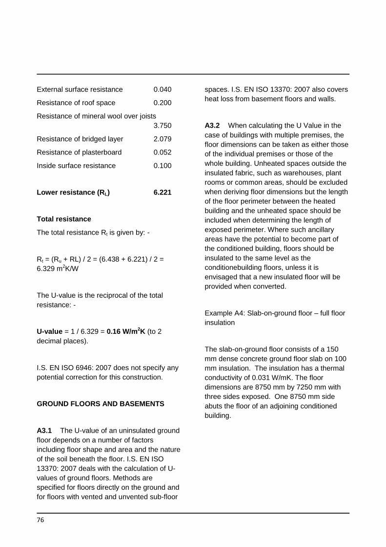
76
External surface resistance 0.040
Resistance of roof space 0.200
Resistance of mineral wool over joists
3.750
Resistance of bridged layer 2.079
Resistance of plasterboard 0.052
Inside surface resistance 0.100
Lower resistance (RL) 6.221
Total resistance
The total resistance Rt is given by: -
Rt = (Ru + RL) / 2 = (6.438 + 6.221) / 2 =
6.329 m2K/W
The U-value is the reciprocal of the total
resistance: -
U-value = 1 / 6.329 = 0.16 W/m2K (to 2
decimal places).
I.S. EN ISO 6946: 2007 does not specify any
potential correction for this construction.
GROUND FLOORS AND BASEMENTS
A3.1 The U-value of an uninsulated ground
floor depends on a number of factors
including floor shape and area and the nature
of the soil beneath the floor. I.S. EN ISO
13370: 2007 deals with the calculation of U-
values of ground floors. Methods are
specified for floors directly on the ground and
for floors with vented and unvented sub-floor
spaces. I.S. EN ISO 13370: 2007 also covers
heat loss from basement floors and walls.
A3.2 When calculating the U Value in the
case of buildings with multiple premises, the
floor dimensions can be taken as either those
of the individual premises or those of the
whole building. Unheated spaces outside the
insulated fabric, such as warehouses, plant
rooms or common areas, should be excluded
when deriving floor dimensions but the length
of the floor perimeter between the heated
building and the unheated space should be
included when determining the length of
exposed perimeter. Where such ancillary
areas have the potential to become part of
the conditioned building, floors should be
insulated to the same level as the
conditionebuilding floors, unless it is
envisaged that a new insulated floor will be
provided when converted.
Example A4: Slab-on-ground floor – full floor
insulation
The slab-on-ground floor consists of a 150
mm dense concrete ground floor slab on 100
mm insulation. The insulation has a thermal
conductivity of 0.031 W/mK. The floor
dimensions are 8750 mm by 7250 mm with
three sides exposed. One 8750 mm side
abuts the floor of an adjoining conditioned
building.
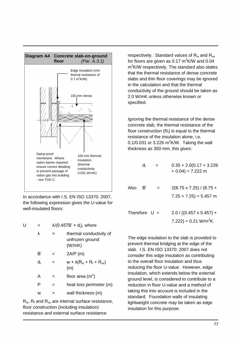
77
Diagram A4 Concrete slab-on-ground floor (Par. A.3.1)
In accordance with I.S. EN ISO 13370: 2007,
the following expression gives the U-value for
well-insulated floors:
U = λ/(0.457B’ + dt), where
λ = thermal conductivity of
unfrozen ground
(W/mK)
B’ = 2A/P (m)
dt = w + λ(Rsi + Rf + Rse)
(m)
A = floor area (m2)
P = heat loss perimeter (m)
w = wall thickness (m)
Rsi, Rf and Rse are internal surface resistance,
floor construction (including insulation)
resistance and external surface resistance
respectively. Standard values of Rsi and Rse
for floors are given as 0.17 m2K/W and 0.04
m2K/W respectively. The standard also states
that the thermal resistance of dense concrete
slabs and thin floor coverings may be ignored
in the calculation and that the thermal
conductivity of the ground should be taken as
2.0 W/mK unless otherwise known or
specified.
Ignoring the thermal resistance of the dense
concrete slab, the thermal resistance of the
floor construction (Rf) is equal to the thermal
resistance of the insulation alone, i.e.
0.1/0.031 or 3.226 m2K/W. Taking the wall
thickness as 350 mm, this gives:
dt = 0.35 + 2.0(0.17 + 3.226
+ 0.04) = 7.222 m
Also B’ = 2(8.75 x 7.25) / (8.75 +
7.25 + 7.25) = 5.457 m
Therefore U = 2.0 / ((0.457 x 5.457) +
7.222) = 0.21 W/m2K.
The edge insulation to the slab is provided to
prevent thermal bridging at the edge of the
slab. I.S. EN ISO 13370: 2007 does not
consider this edge insulation as contributing
to the overall floor insulation and thus
reducing the floor U-value. However, edge
insulation, which extends below the external
ground level, is considered to contribute to a
reduction in floor U-value and a method of
taking this into account is included in the
standard. Foundation walls of insulating
lightweight concrete may be taken as edge
insulation for this purpose.
Damp proof
membrane. Where
radon barrier required,
ensure correct detailing
to prevent passage of
radon gas into building
- see TGD C.
100 mm thermal
insulation
(thermal
conductivity
0.031 W/mK)
Edge insulation (min
themal resistance of
0.7 m2K/W)
150 mm dense
concrete
78
ELEMENTS ADJACENT TO UNHEATED SPACES
A4.1 As indicated in paragraph 0.3.5, the procedure for the calculation of U-values of elements adjacent to unheated spaces (previously referred to as semi-exposed elements) is given in I.S. EN ISO 6946: 2007 and I.S. EN ISO 13789: 2007.
Other cases In other cases R12 should be calculated using the following formula Ru = _________ Ai_____________
Σ[Ae x Ue] +0.33nV
Where Ai and Ae are the areas of internal and external elements (m2), Excluding any ground floor; Ue is the U value of external elements (W/m2 K) and n is the air exchange rate (ach) of the unheated space (m3). Typical values of the air exchange rate in unheated spaces are given in the Table A5. The default value of n = 3ach should be used if the airtightness of the unheated space is not known. Table A 5 typical air change rates for unheated spaces
Airtightness type
Air changes per hour
No doors or windows, all joints between components well-sealed, no ventilation openings provided
0.1
All joints between components well sealed, no ventilation openings provided
0.5
All joints well-sealed, small openings or permanent ventilation openings
1.0
Not airtight due to some localised open joints or permanent ventilation openings
3.0
Not airtight due to numerous open joints, or large or numerous permanent ventilation openings
10.0
The following formulae may be used to derive elemental U-values (taking the unheated space into account) for typical building situations irrespective of the precise dimensions of the unheated space.
Uo = 1 / (1/U-Ru) or U = 1 / (1/Uo+Ru)
Where:
U = U-value of element adjacent to unheated space (W/m2K), taking the effect of the unheated space into account.
Uo = U-value of the element between heated and unheated spaces (W/m2K) calculated as if there was no unheated space adjacent to the element.
Ru = effective thermal resistance of unheated space inclusive of all external elements (m2K/W).
Appendix B Fabric Insulation : Additional Guidance for Common Constructions
79
GENERAL
B.1 This Appendix provides some basic
guidance in relation to typical roof, wall and
floor constructions. Guidance is not
exhaustive and designers and contractors
should also have regard to other sources of
relevant guidance, e.g. BR.262: 2001.
Thermal Insulation; avoiding risks, relevant
standards and good building practice.
In particular, diagrams in this Appendix are
intended to be illustrative of the construction
to which they refer. They do not purport to
provide detailed guidance on the avoidance
of thermal bridging. See sections 1.3.3, 2.1.3
and Limiting Thermal Bridging and Air
Infiltration - Acceptable Construction Details
(ACDs) for guidance on reasonable provision
in this regard.
B.2 For many typical roof, wall and floor
constructions, the thickness of insulation
required to achieve a particular U-value can
vary depending on the thermal performance
of the insulation material. Higher performing
insulating materials, i.e. those with lower
thermal conductivities, can achieve any given
U-value with a lower thickness of insulating
material.
B.3 Condensation in buildings occurs
whenever warm moist air meets surfaces that
are at or below the dew point of that air.
There are two main types, surface
condensation and interstitial condensation.
Surface condensation occurs on the surface
of walls, windows, ceilings and floors and
may result in mould and mildew.
Interstitial condensation occurs within the
construction of the building and can damage
structural materials or make insulating
materials less effective.
Full checks should be performed on the
likelihood of surface and interstitial
condensation of a construction detail in
accordance with I.S. EN ISO 13788:2012.
This standard contains recommended
procedures for the assessment of the risk of:
surface condensation and mould
growth;
interstitial condensation.
The guidance in BRE document BR 497
Conventions for calculating linear thermal
transmittance and temperature factors (2nd
Edition) may be used to perform the checks
in IS EN ISO 13788:2012.
IS EN 15026:2007 can also be used to
assess the risk of surface condensation and
mould growth. The transient models covered
in this standard take account of heat and
moisture storage, latent heat effects, and
liquid and convective transport under realistic
boundary and initial conditions.
B.4 A vapour control layer (VCL)
substantially reduces the water vapour
transfer through any building component in
which it is incorporated by limiting both
vapour diffusion and air movement. The
measures required to achieve a functional
VCL must be carefully considered at the
design stage.
A VCL should extend over the whole of the
element into which it is incorporated and must
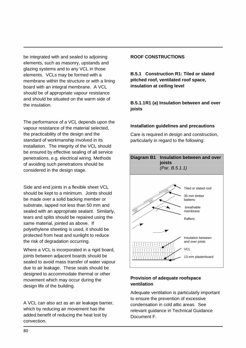
80
be integrated with and sealed to adjoining
elements, such as masonry, upstands and
glazing systems and to any VCL in those
elements. VCLs may be formed with a
membrane within the structure or with a lining
board with an integral membrane. A VCL
should be of appropriate vapour resistance
and should be situated on the warm side of
the insulation.
The performance of a VCL depends upon the
vapour resistance of the material selected,
the practicability of the design and the
standard of workmanship involved in its
installation. The integrity of the VCL should
be ensured by effective sealing of all service
penetrations, e.g. electrical wiring. Methods
of avoiding such penetrations should be
considered in the design stage.
Side and end joints in a flexible sheet VCL
should be kept to a minimum. Joints should
be made over a solid backing member or
substrate, lapped not less than 50 mm and
sealed with an appropriate sealant. Similarly,
tears and splits should be repaired using the
same material, jointed as above. If
polyethylene sheeting is used, it should be
protected from heat and sunlight to reduce
the risk of degradation occurring.
Where a VCL is incorporated in a rigid board,
joints between adjacent boards should be
sealed to avoid mass transfer of water vapour
due to air leakage. These seals should be
designed to accommodate thermal or other
movement which may occur during the
design life of the building.
A VCL can also act as an air leakage barrier,
which by reducing air movement has the
added benefit of reducing the heat lost by
convection.
ROOF CONSTRUCTIONS
B.5.1 Construction R1: Tiled or slated
pitched roof, ventilated roof space,
insulation at ceiling level
B.5.1.1 R1 (a) Insulation between and over
joists
Installation guidelines and precautions
Care is required in design and construction,
particularly in regard to the following:
Diagram B1 Insulation between and over joists (Par. B.5.1.1)
Provision of adequate roofspace
ventilation
Adequate ventilation is particularly important
to ensure the prevention of excessive
condensation in cold attic areas. See
relevant guidance in Technical Guidance
Document F.
Tiled or slated roof 35 mm timber battens breathable membrane Rafters Insulation between and over joists VCL 13 mm plasterboard
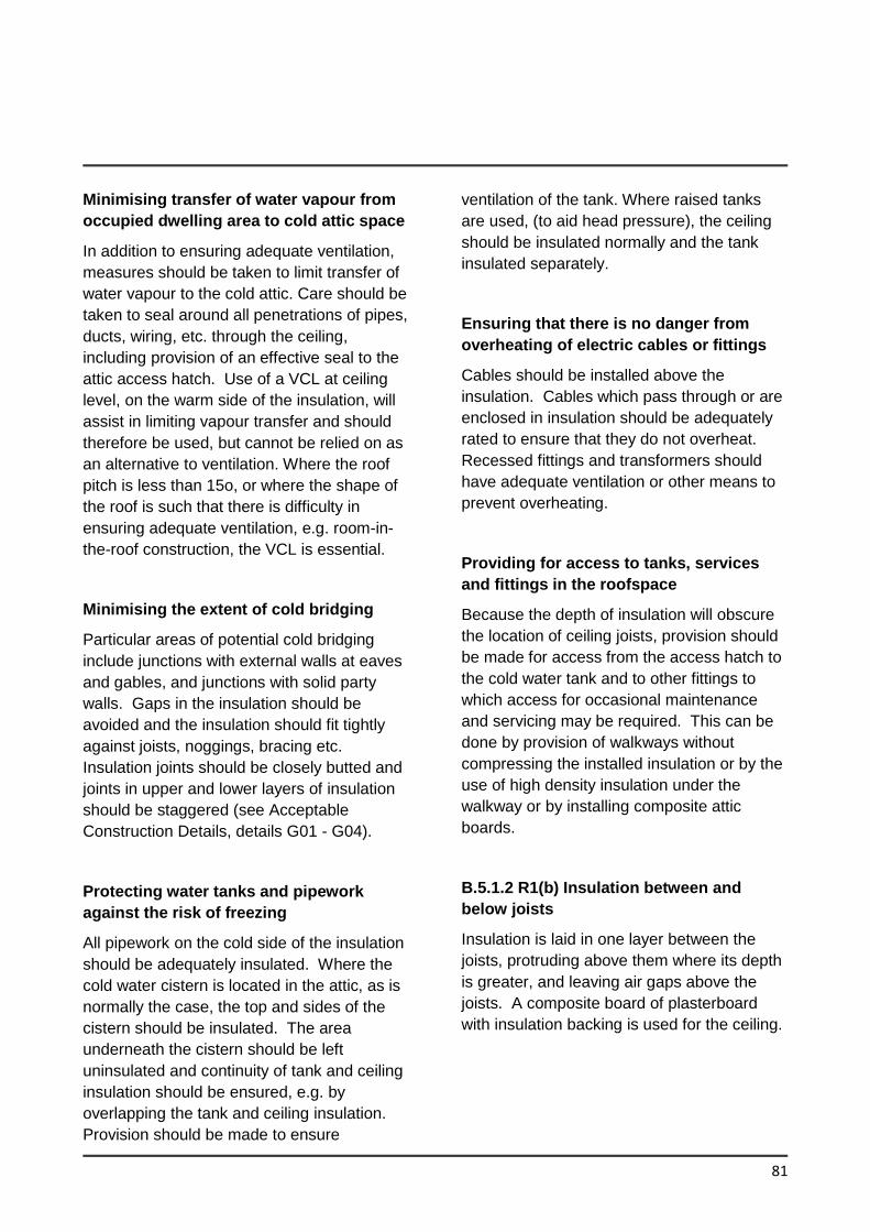
81
Minimising transfer of water vapour from
occupied dwelling area to cold attic space
In addition to ensuring adequate ventilation,
measures should be taken to limit transfer of
water vapour to the cold attic. Care should be
taken to seal around all penetrations of pipes,
ducts, wiring, etc. through the ceiling,
including provision of an effective seal to the
attic access hatch. Use of a VCL at ceiling
level, on the warm side of the insulation, will
assist in limiting vapour transfer and should
therefore be used, but cannot be relied on as
an alternative to ventilation. Where the roof
pitch is less than 15o, or where the shape of
the roof is such that there is difficulty in
ensuring adequate ventilation, e.g. room-in-
the-roof construction, the VCL is essential.
Minimising the extent of cold bridging
Particular areas of potential cold bridging
include junctions with external walls at eaves
and gables, and junctions with solid party
walls. Gaps in the insulation should be
avoided and the insulation should fit tightly
against joists, noggings, bracing etc.
Insulation joints should be closely butted and
joints in upper and lower layers of insulation
should be staggered (see Acceptable
Construction Details, details G01 - G04).
Protecting water tanks and pipework
against the risk of freezing
All pipework on the cold side of the insulation
should be adequately insulated. Where the
cold water cistern is located in the attic, as is
normally the case, the top and sides of the
cistern should be insulated. The area
underneath the cistern should be left
uninsulated and continuity of tank and ceiling
insulation should be ensured, e.g. by
overlapping the tank and ceiling insulation.
Provision should be made to ensure
ventilation of the tank. Where raised tanks
are used, (to aid head pressure), the ceiling
should be insulated normally and the tank
insulated separately.
Ensuring that there is no danger from
overheating of electric cables or fittings
Cables should be installed above the
insulation. Cables which pass through or are
enclosed in insulation should be adequately
rated to ensure that they do not overheat.
Recessed fittings and transformers should
have adequate ventilation or other means to
prevent overheating.
Providing for access to tanks, services
and fittings in the roofspace
Because the depth of insulation will obscure
the location of ceiling joists, provision should
be made for access from the access hatch to
the cold water tank and to other fittings to
which access for occasional maintenance
and servicing may be required. This can be
done by provision of walkways without
compressing the installed insulation or by the
use of high density insulation under the
walkway or by installing composite attic
boards.
B.5.1.2 R1(b) Insulation between and
below joists
Insulation is laid in one layer between the
joists, protruding above them where its depth
is greater, and leaving air gaps above the
joists. A composite board of plasterboard
with insulation backing is used for the ceiling.
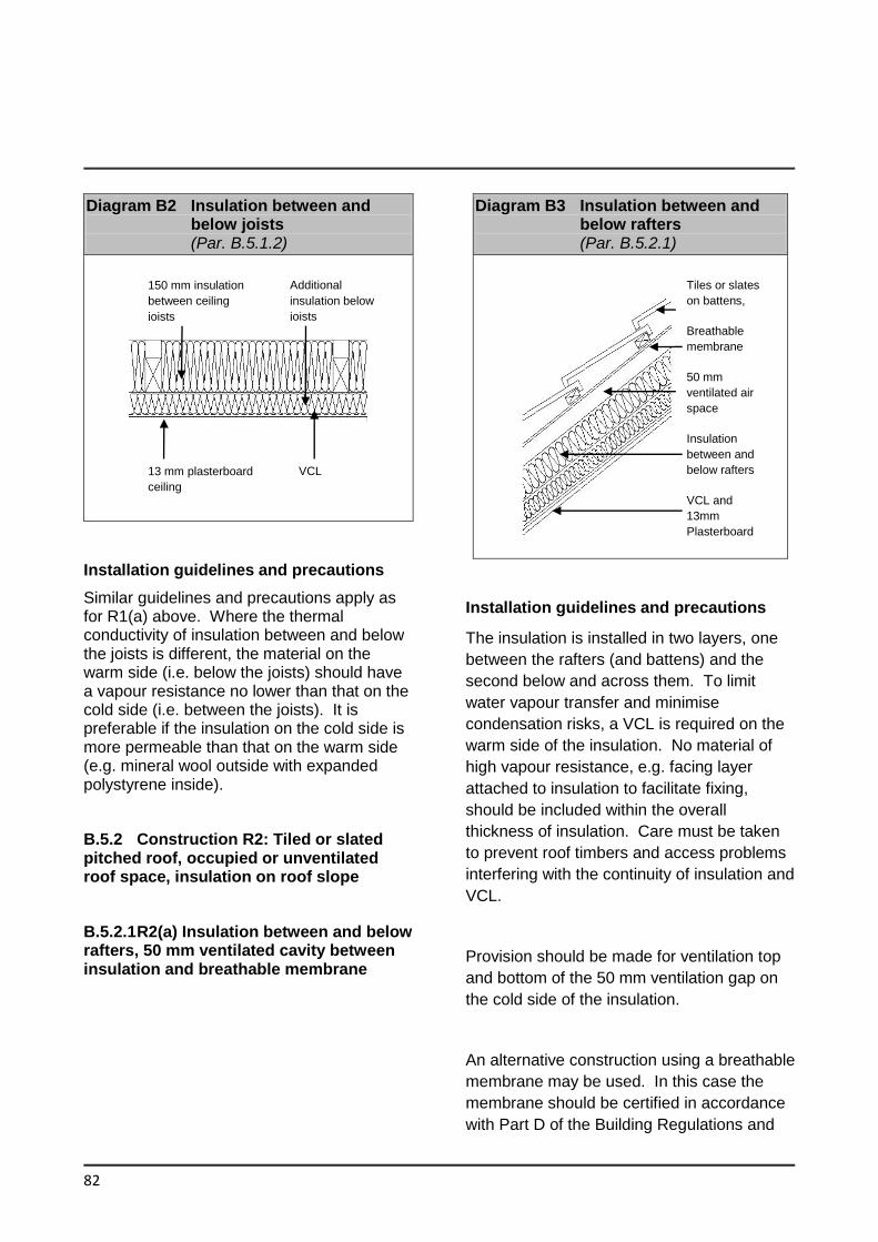
82
Diagram B2 Insulation between and below joists (Par. B.5.1.2)
Installation guidelines and precautions
Similar guidelines and precautions apply as for R1(a) above. Where the thermal conductivity of insulation between and below the joists is different, the material on the warm side (i.e. below the joists) should have a vapour resistance no lower than that on the cold side (i.e. between the joists). It is preferable if the insulation on the cold side is more permeable than that on the warm side (e.g. mineral wool outside with expanded polystyrene inside).
B.5.2 Construction R2: Tiled or slated pitched roof, occupied or unventilated roof space, insulation on roof slope
B.5.2.1 R2(a) Insulation between and below rafters, 50 mm ventilated cavity between insulation and breathable membrane
Diagram B3 Insulation between and below rafters (Par. B.5.2.1)
Installation guidelines and precautions
The insulation is installed in two layers, one
between the rafters (and battens) and the
second below and across them. To limit
water vapour transfer and minimise
condensation risks, a VCL is required on the
warm side of the insulation. No material of
high vapour resistance, e.g. facing layer
attached to insulation to facilitate fixing,
should be included within the overall
thickness of insulation. Care must be taken
to prevent roof timbers and access problems
interfering with the continuity of insulation and
VCL.
Provision should be made for ventilation top
and bottom of the 50 mm ventilation gap on
the cold side of the insulation.
An alternative construction using a breathable
membrane may be used. In this case the
membrane should be certified in accordance
with Part D of the Building Regulations and
150 mm insulation
between ceiling
joists
VCL 13 mm plasterboard
ceiling
Additional
insulation below
joists
Tiles or slates
on battens,
Breathable
membrane
50 mm
ventilated air
space
Insulation
between and
below rafters
VCL and
13mm
Plasterboard
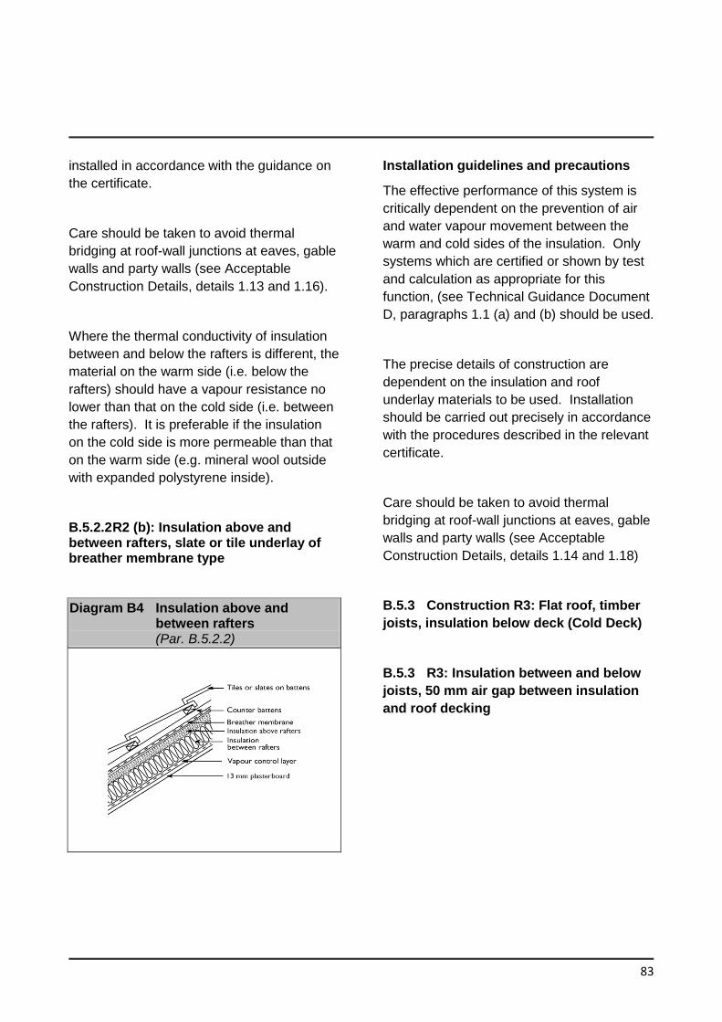
83
installed in accordance with the guidance on
the certificate.
Care should be taken to avoid thermal
bridging at roof-wall junctions at eaves, gable
walls and party walls (see Acceptable
Construction Details, details 1.13 and 1.16).
Where the thermal conductivity of insulation
between and below the rafters is different, the
material on the warm side (i.e. below the
rafters) should have a vapour resistance no
lower than that on the cold side (i.e. between
the rafters). It is preferable if the insulation
on the cold side is more permeable than that
on the warm side (e.g. mineral wool outside
with expanded polystyrene inside).
B.5.2.2 R2 (b): Insulation above and between rafters, slate or tile underlay of breather membrane type
Diagram B4 Insulation above and between rafters (Par. B.5.2.2)
Installation guidelines and precautions
The effective performance of this system is
critically dependent on the prevention of air
and water vapour movement between the
warm and cold sides of the insulation. Only
systems which are certified or shown by test
and calculation as appropriate for this
function, (see Technical Guidance Document
D, paragraphs 1.1 (a) and (b) should be used.
The precise details of construction are
dependent on the insulation and roof
underlay materials to be used. Installation
should be carried out precisely in accordance
with the procedures described in the relevant
certificate.
Care should be taken to avoid thermal
bridging at roof-wall junctions at eaves, gable
walls and party walls (see Acceptable
Construction Details, details 1.14 and 1.18)
B.5.3 Construction R3: Flat roof, timber
joists, insulation below deck (Cold Deck)
B.5.3 R3: Insulation between and below
joists, 50 mm air gap between insulation
and roof decking
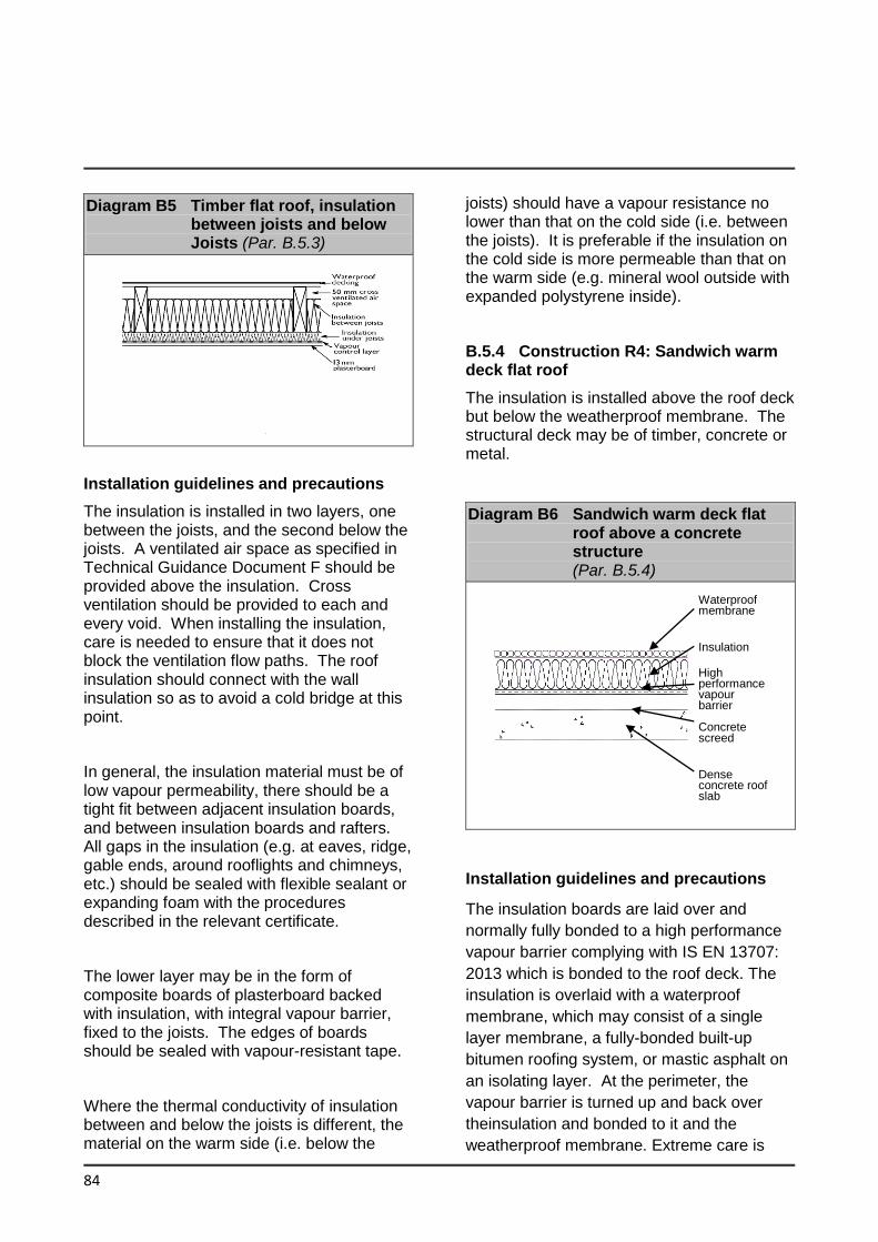
84
Diagram B5 Timber flat roof, insulation between joists and below Joists (Par. B.5.3)
Installation guidelines and precautions
The insulation is installed in two layers, one between the joists, and the second below the joists. A ventilated air space as specified in Technical Guidance Document F should be provided above the insulation. Cross ventilation should be provided to each and every void. When installing the insulation, care is needed to ensure that it does not block the ventilation flow paths. The roof insulation should connect with the wall insulation so as to avoid a cold bridge at this point.
In general, the insulation material must be of low vapour permeability, there should be a tight fit between adjacent insulation boards, and between insulation boards and rafters. All gaps in the insulation (e.g. at eaves, ridge, gable ends, around rooflights and chimneys, etc.) should be sealed with flexible sealant or expanding foam with the procedures described in the relevant certificate.
The lower layer may be in the form of composite boards of plasterboard backed with insulation, with integral vapour barrier, fixed to the joists. The edges of boards should be sealed with vapour-resistant tape.
Where the thermal conductivity of insulation between and below the joists is different, the material on the warm side (i.e. below the
joists) should have a vapour resistance no lower than that on the cold side (i.e. between the joists). It is preferable if the insulation on the cold side is more permeable than that on the warm side (e.g. mineral wool outside with expanded polystyrene inside).
B.5.4 Construction R4: Sandwich warm deck flat roof
The insulation is installed above the roof deck but below the weatherproof membrane. The structural deck may be of timber, concrete or metal.
Diagram B6 Sandwich warm deck flat roof above a concrete structure (Par. B.5.4)
Installation guidelines and precautions
The insulation boards are laid over and
normally fully bonded to a high performance
vapour barrier complying with IS EN 13707:
2013 which is bonded to the roof deck. The
insulation is overlaid with a waterproof
membrane, which may consist of a single
layer membrane, a fully-bonded built-up
bitumen roofing system, or mastic asphalt on
an isolating layer. At the perimeter, the
vapour barrier is turned up and back over
theinsulation and bonded to it and the
weatherproof membrane. Extreme care is
Waterproof membrane
Insulation
High performance vapour barrier Concrete screed
Dense concrete roof slab
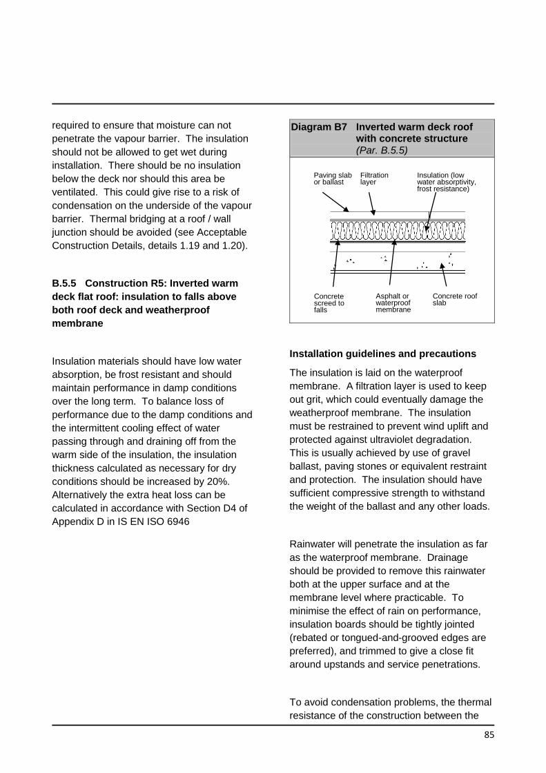
85
required to ensure that moisture can not
penetrate the vapour barrier. The insulation
should not be allowed to get wet during
installation. There should be no insulation
below the deck nor should this area be
ventilated. This could give rise to a risk of
condensation on the underside of the vapour
barrier. Thermal bridging at a roof / wall
junction should be avoided (see Acceptable
Construction Details, details 1.19 and 1.20).
B.5.5 Construction R5: Inverted warm
deck flat roof: insulation to falls above
both roof deck and weatherproof
membrane
Insulation materials should have low water
absorption, be frost resistant and should
maintain performance in damp conditions
over the long term. To balance loss of
performance due to the damp conditions and
the intermittent cooling effect of water
passing through and draining off from the
warm side of the insulation, the insulation
thickness calculated as necessary for dry
conditions should be increased by 20%.
Alternatively the extra heat loss can be
calculated in accordance with Section D4 of
Appendix D in IS EN ISO 6946
Diagram B7 Inverted warm deck roof with concrete structure (Par. B.5.5)
Installation guidelines and precautions
The insulation is laid on the waterproof
membrane. A filtration layer is used to keep
out grit, which could eventually damage the
weatherproof membrane. The insulation
must be restrained to prevent wind uplift and
protected against ultraviolet degradation.
This is usually achieved by use of gravel
ballast, paving stones or equivalent restraint
and protection. The insulation should have
sufficient compressive strength to withstand
the weight of the ballast and any other loads.
Rainwater will penetrate the insulation as far
as the waterproof membrane. Drainage
should be provided to remove this rainwater
both at the upper surface and at the
membrane level where practicable. To
minimise the effect of rain on performance,
insulation boards should be tightly jointed
(rebated or tongued-and-grooved edges are
preferred), and trimmed to give a close fit
around upstands and service penetrations.
To avoid condensation problems, the thermal
resistance of the construction between the
Paving slab or ballast
Filtration layer
Insulation (low water absorptivity, frost resistance)
Asphalt or waterproof membrane
Concrete screed to falls
Concrete roof slab
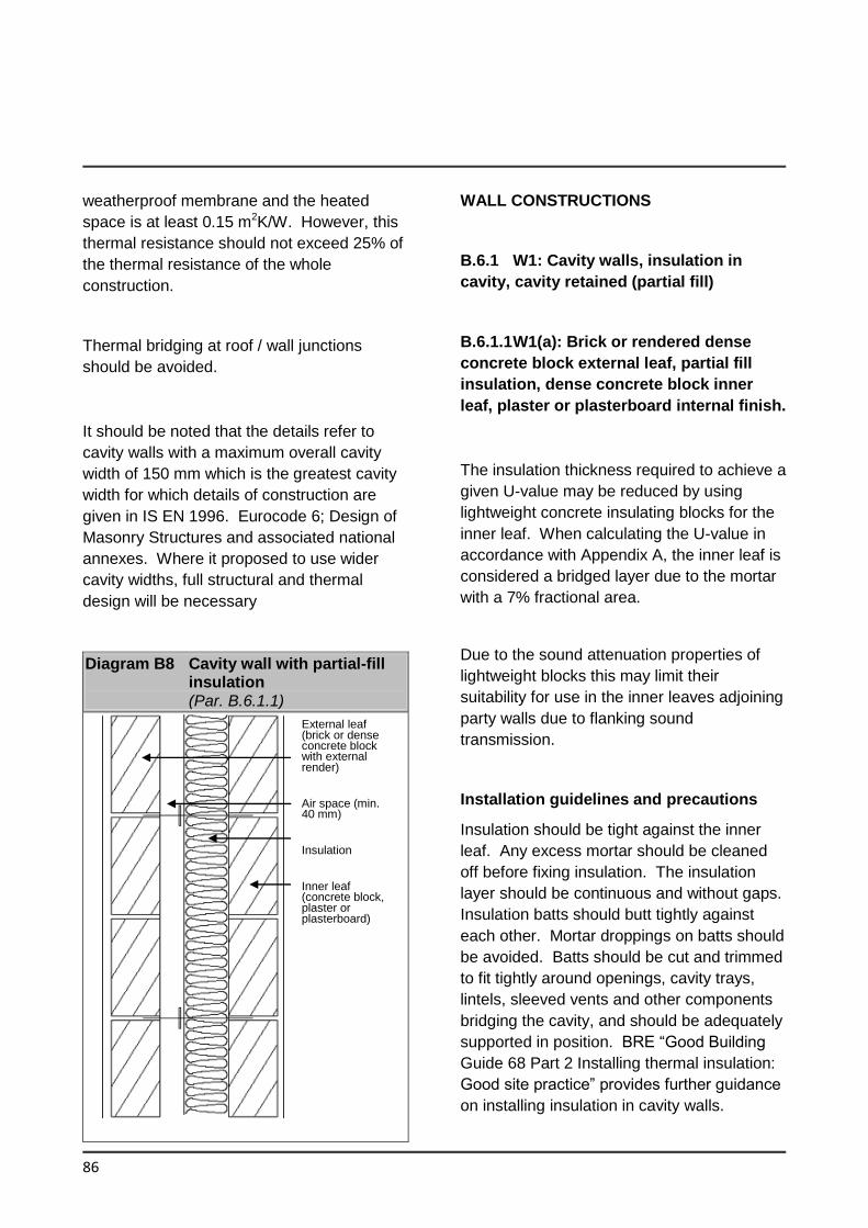
86
weatherproof membrane and the heated
space is at least 0.15 m2K/W. However, this
thermal resistance should not exceed 25% of
the thermal resistance of the whole
construction.
Thermal bridging at roof / wall junctions
should be avoided.
WALL CONSTRUCTIONS
B.6.1 W1: Cavity walls, insulation in
cavity, cavity retained (partial fill)
B.6.1.1 W1(a): Brick or rendered dense
concrete block external leaf, partial fill
insulation, dense concrete block inner
leaf, plaster or plasterboard internal finish.
It should be noted that the details refer to
cavity walls with a maximum overall cavity
width of 150 mm which is the greatest cavity
width for which details of construction are
given in IS EN 1996. Eurocode 6; Design of
Masonry Structures and associated national
annexes. Where it proposed to use wider
cavity widths, full structural and thermal
design will be necessary
Diagram B8 Cavity wall with partial-fill insulation (Par. B.6.1.1)
The insulation thickness required to achieve a
given U-value may be reduced by using
lightweight concrete insulating blocks for the
inner leaf. When calculating the U-value in
accordance with Appendix A, the inner leaf is
considered a bridged layer due to the mortar
with a 7% fractional area.
Due to the sound attenuation properties of
lightweight blocks this may limit their
suitability for use in the inner leaves adjoining
party walls due to flanking sound
transmission.
Installation guidelines and precautions
Insulation should be tight against the inner
leaf. Any excess mortar should be cleaned
off before fixing insulation. The insulation
layer should be continuous and without gaps.
Insulation batts should butt tightly against
each other. Mortar droppings on batts should
be avoided. Batts should be cut and trimmed
to fit tightly around openings, cavity trays,
lintels, sleeved vents and other components
bridging the cavity, and should be adequately
supported in position. BRE “Good Building
Guide 68 Part 2 Installing thermal insulation:
Good site practice” provides further guidance
on installing insulation in cavity walls.
External leaf (brick or dense concrete block with external render)
Air space (min. 40 mm)
Insulation
Inner leaf (concrete block, plaster or plasterboard)
87
Critical locations where care should be taken
to limit thermal bridging include lintels, jambs,
cills, roof-wall junctions and wall-floor
junctions. The method of cavity closure used
should not cause thermal bridge at the roof-
wall junction (see Acceptable Construction
Details, Group 1 details)
B.6.1.2 W1(b): As W1(a) except with
insulation partly in cavity and partly as
internal lining
If composite boards of plasterboard backed
with insulation (of similar conductivity to that
used in the cavity) are used internally then
the total insulation thickness (cavity plus
internal) may be used to calculate the U-
value. If internal insulation is placed between
timber studs / battens, then the insulation
must be treated as two separate layers with
the bridging effect allowed for in the internal
layer (similar to example A2 in Appendix A).
Where the thermal conductivity of the
insulation is different, the material on the
warm side (i.e. internally) should have a
vapour resistance no lower than the
insulation on the cold side (i.e. in the cavity).
Lower U-values, or reduced insulation
thickness, can be achieved by using
insulating concrete blockwork (rather than
dense concrete) between the cavity and
internal insulation.
Insulation partly in cavity and partly as
internal lining helps minimise thermal
bridging. Internal insulation limits thermal
bridging at floor and roof junctions, whereas
cavity insulation minimises thermal bridging
at separating walls and internal fixtures.
Installation guidelines and precautions
Installation of insulation in the cavity should
follow the guidelines given above for
construction W1(a) (partial-fill cavity
insulation), and installation of the internal
lining should follow the guidelines given
below for construction W4 (hollow-block).
BRE “Good Building Guide 68 Part 2
Installing thermal insulation: Good site
practice” provides further guidance on
installing insulation in cavity walls.
B.6.2 Construction W2: Cavity walls,
insulation in cavity, no residual cavity
(full-fill)
The insulation fully fills the cavity. Insulation
may be in the form of semi-rigid batts
installed as wall construction proceeds, or
loose-fill material blown into the cavity after
the wall is constructed; the former is
considered here. Insulation material suitable
for cavity fill should not absorb water by
capillary action and should not transmit water
from outer to inner leaf. Such insulation may
extend below dpc level.
The insulation thickness required to achieve a
given U-value may be reduced by using
insulating concrete blocks for the inner leaf,
as advised in W1(a) above.
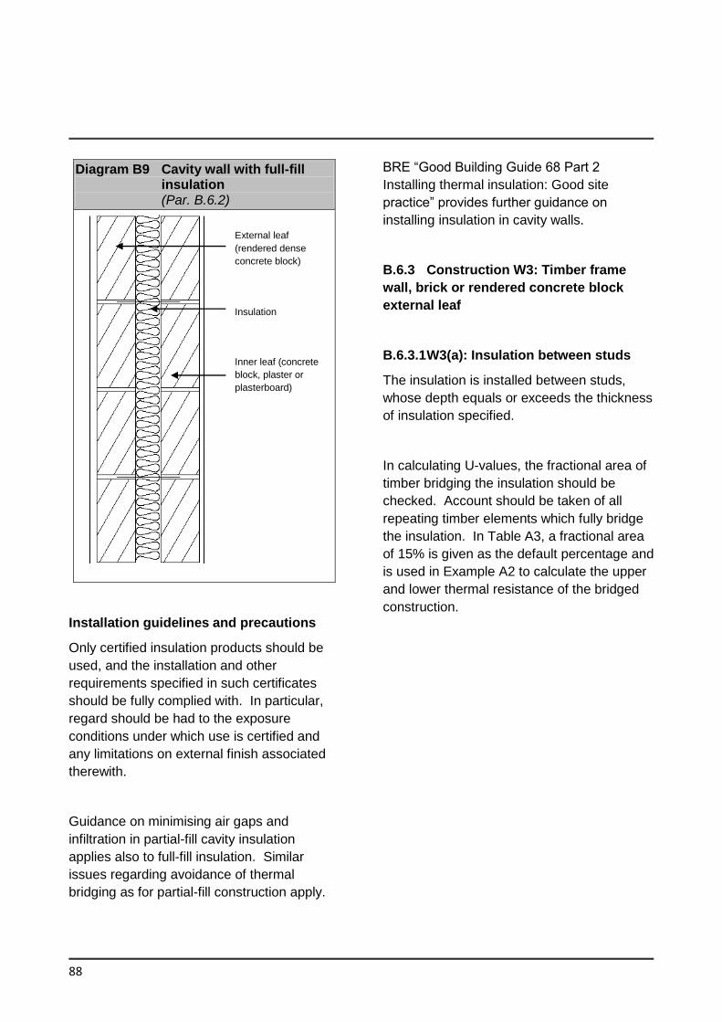
88
Diagram B9 Cavity wall with full-fill insulation (Par. B.6.2)
Installation guidelines and precautions
Only certified insulation products should be
used, and the installation and other
requirements specified in such certificates
should be fully complied with. In particular,
regard should be had to the exposure
conditions under which use is certified and
any limitations on external finish associated
therewith.
Guidance on minimising air gaps and
infiltration in partial-fill cavity insulation
applies also to full-fill insulation. Similar
issues regarding avoidance of thermal
bridging as for partial-fill construction apply.
BRE “Good Building Guide 68 Part 2
Installing thermal insulation: Good site
practice” provides further guidance on
installing insulation in cavity walls.
B.6.3 Construction W3: Timber frame
wall, brick or rendered concrete block
external leaf
B.6.3.1 W3(a): Insulation between studs
The insulation is installed between studs,
whose depth equals or exceeds the thickness
of insulation specified.
In calculating U-values, the fractional area of
timber bridging the insulation should be
checked. Account should be taken of all
repeating timber elements which fully bridge
the insulation. In Table A3, a fractional area
of 15% is given as the default percentage and
is used in Example A2 to calculate the upper
and lower thermal resistance of the bridged
construction.
External leaf
(rendered dense
concrete block)
Insulation
Inner leaf (concrete
block, plaster or
plasterboard)
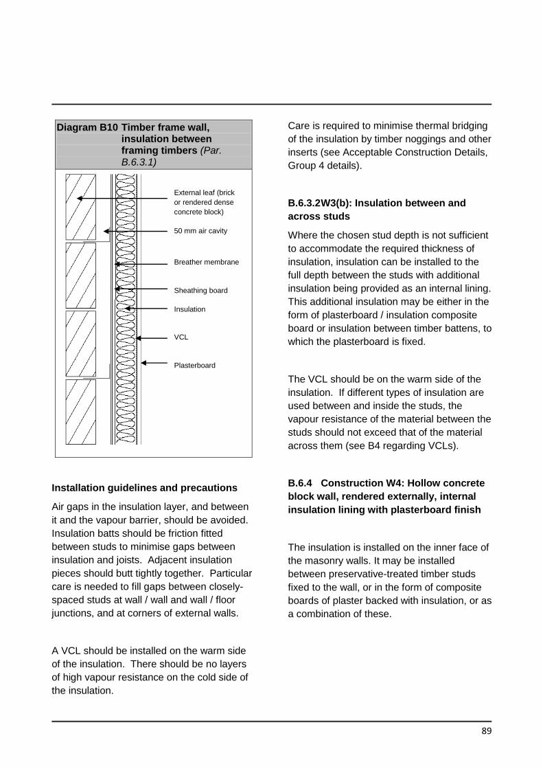
89
Diagram B10 Timber frame wall, insulation between framing timbers (Par. B.6.3.1)
Installation guidelines and precautions
Air gaps in the insulation layer, and between
it and the vapour barrier, should be avoided.
Insulation batts should be friction fitted
between studs to minimise gaps between
insulation and joists. Adjacent insulation
pieces should butt tightly together. Particular
care is needed to fill gaps between closely-
spaced studs at wall / wall and wall / floor
junctions, and at corners of external walls.
A VCL should be installed on the warm side
of the insulation. There should be no layers
of high vapour resistance on the cold side of
the insulation.
Care is required to minimise thermal bridging
of the insulation by timber noggings and other
inserts (see Acceptable Construction Details,
Group 4 details).
B.6.3.2 W3(b): Insulation between and
across studs
Where the chosen stud depth is not sufficient
to accommodate the required thickness of
insulation, insulation can be installed to the
full depth between the studs with additional
insulation being provided as an internal lining.
This additional insulation may be either in the
form of plasterboard / insulation composite
board or insulation between timber battens, to
which the plasterboard is fixed.
The VCL should be on the warm side of the
insulation. If different types of insulation are
used between and inside the studs, the
vapour resistance of the material between the
studs should not exceed that of the material
across them (see B4 regarding VCLs).
B.6.4 Construction W4: Hollow concrete
block wall, rendered externally, internal
insulation lining with plasterboard finish
The insulation is installed on the inner face of
the masonry walls. It may be installed
between preservative-treated timber studs
fixed to the wall, or in the form of composite
boards of plaster backed with insulation, or as
a combination of these.
External leaf (brick
or rendered dense
concrete block)
50 mm air cavity
Breather membrane
Sheathing board
Insulation
VCL
Plasterboard
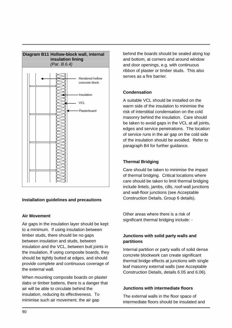
90
Diagram B11 Hollow-block wall, internal insulation lining (Par. B.6.4)
Installation guidelines and precautions
Air Movement
Air gaps in the insulation layer should be kept
to a minimum. If using insulation between
timber studs, there should be no gaps
between insulation and studs, between
insulation and the VCL, between butt joints in
the insulation, If using composite boards, they
should be tightly butted at edges, and should
provide complete and continuous coverage of
the external wall.
When mounting composite boards on plaster
dabs or timber battens, there is a danger that
air will be able to circulate behind the
insulation, reducing its effectiveness. To
minimise such air movement, the air gap
behind the boards should be sealed along top
and bottom, at corners and around window
and door openings, e.g. with continuous
ribbon of plaster or timber studs. This also
serves as a fire barrier.
Condensation
A suitable VCL should be installed on the
warm side of the insulation to minimise the
risk of interstitial condensation on the cold
masonry behind the insulation. Care should
be taken to avoid gaps in the VCL at all joints,
edges and service penetrations. The location
of service runs in the air gap on the cold side
of the insulation should be avoided. Refer to
paragraph B4 for further guidance.
Thermal Bridging
Care should be taken to minimise the impact
of thermal bridging. Critical locations where
care should be taken to limit thermal bridging
include lintels, jambs, cills, roof-wall junctions
and wall-floor junctions (see Acceptable
Construction Details, Group 6 details).
Other areas where there is a risk of
significant thermal bridging include: -
Junctions with solid party walls and
partitions
Internal partition or party walls of solid dense
concrete blockwork can create significant
thermal bridge effects at junctions with single
leaf masonry external walls (see Acceptable
Construction Details, details 6.05 and 6.06).
Junctions with intermediate floors
The external walls in the floor space of
intermediate floors should be insulated and
Rendered hollow
concrete block
Insulation
VCL
Plasterboard
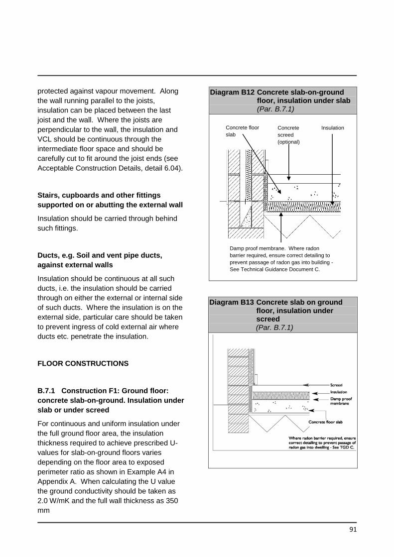
91
protected against vapour movement. Along
the wall running parallel to the joists,
insulation can be placed between the last
joist and the wall. Where the joists are
perpendicular to the wall, the insulation and
VCL should be continuous through the
intermediate floor space and should be
carefully cut to fit around the joist ends (see
Acceptable Construction Details, detail 6.04).
Stairs, cupboards and other fittings
supported on or abutting the external wall
Insulation should be carried through behind
such fittings.
Ducts, e.g. Soil and vent pipe ducts,
against external walls
Insulation should be continuous at all such
ducts, i.e. the insulation should be carried
through on either the external or internal side
of such ducts. Where the insulation is on the
external side, particular care should be taken
to prevent ingress of cold external air where
ducts etc. penetrate the insulation.
FLOOR CONSTRUCTIONS
B.7.1 Construction F1: Ground floor:
concrete slab-on-ground. Insulation under
slab or under screed
For continuous and uniform insulation under
the full ground floor area, the insulation
thickness required to achieve prescribed U-
values for slab-on-ground floors varies
depending on the floor area to exposed
perimeter ratio as shown in Example A4 in
Appendix A. When calculating the U value
the ground conductivity should be taken as
2.0 W/mK and the full wall thickness as 350
mm
Diagram B12 Concrete slab-on-ground floor, insulation under slab (Par. B.7.1)
Diagram B13 Concrete slab on ground floor, insulation under screed (Par. B.7.1)
Damp proof membrane. Where radon
barrier required, ensure correct detailing to
prevent passage of radon gas into building -
See Technical Guidance Document C.
Concrete floor
slab
Concrete
screed
(optional)
Insulation
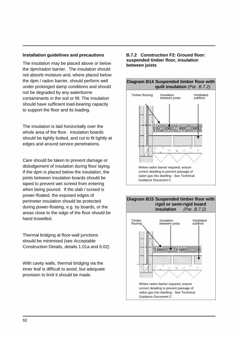
92
Installation guidelines and precautions
The insulation may be placed above or below
the dpm/radon barrier. The insulation should
not absorb moisture and, where placed below
the dpm / radon barrier, should perform well
under prolonged damp conditions and should
not be degraded by any waterborne
contaminants in the soil or fill. The insulation
should have sufficient load-bearing capacity
to support the floor and its loading.
The insulation is laid horizontally over the
whole area of the floor. Insulation boards
should be tightly butted, and cut to fit tightly at
edges and around service penetrations.
Care should be taken to prevent damage or
dislodgement of insulation during floor laying.
If the dpm is placed below the insulation, the
joints between insulation boards should be
taped to prevent wet screed from entering
when being poured. If the slab / screed is
power-floated, the exposed edges of
perimeter insulation should be protected
during power-floating, e.g. by boards, or the
areas close to the edge of the floor should be
hand trowelled.
Thermal bridging at floor-wall junctions
should be minimised (see Acceptable
Construction Details, details 1.01a and 6.02)
With cavity walls, thermal bridging via the
inner leaf is difficult to avoid, but adequate
provision to limit it should be made.
B.7.2 Construction F2: Ground floor: suspended timber floor, insulation between joists
Diagram B14 Suspended timber floor with quilt insulation (Par. B.7.2)
Diagram B15 Suspended timber floor with rigid or semi-rigid board insulation (Par. B.7.2)
Where radon barrier required, ensure
correct detailing to prevent passage of
radon gas into dwelling - See Technical
Guidance Document C.
Timber flooring Insulation between joists
Ventilated subfloor
Where radon barrier required, ensure
correct detailing to prevent passage of
radon gas into dwelling - See Technical
Guidance Document C.
Timber flooring
Insulation between joists
Ventilated subfloor
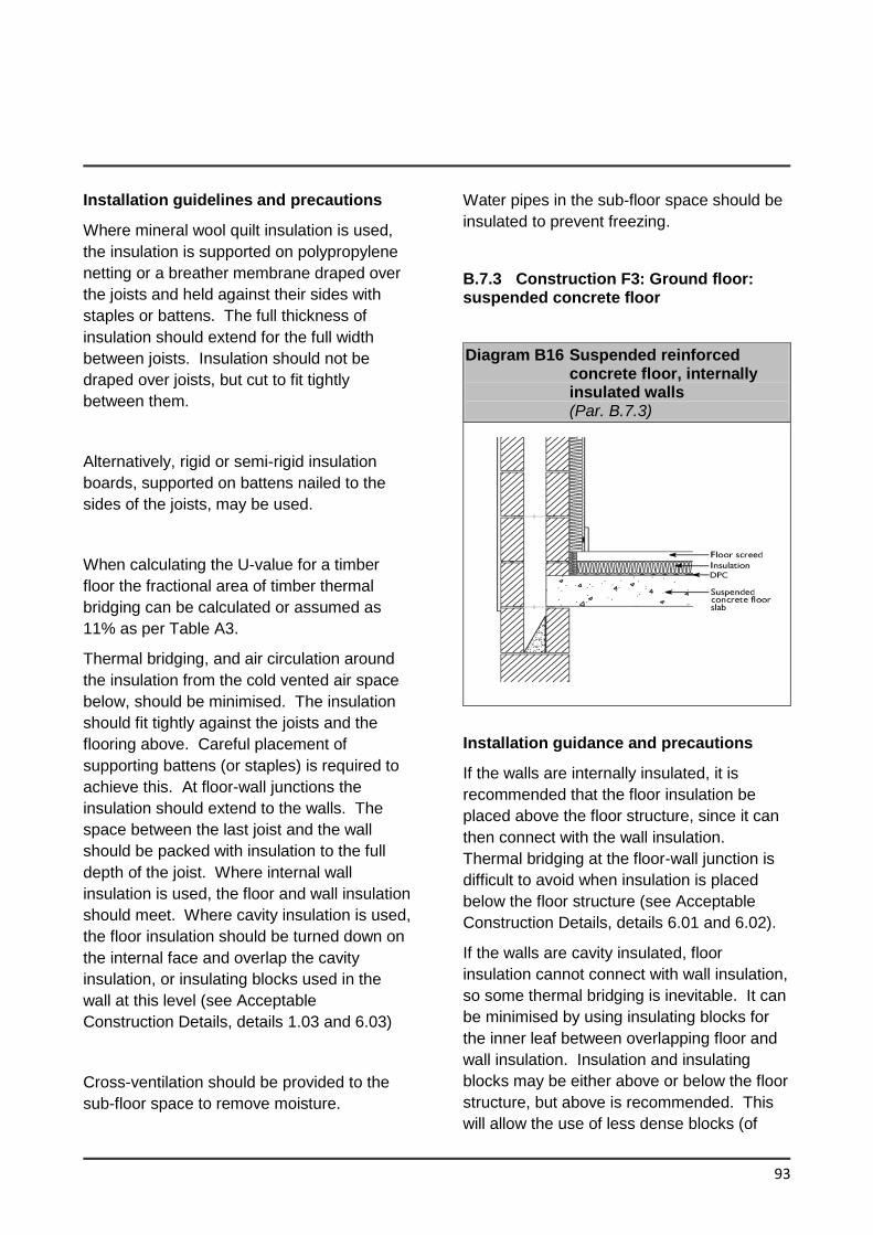
93
Installation guidelines and precautions
Where mineral wool quilt insulation is used,
the insulation is supported on polypropylene
netting or a breather membrane draped over
the joists and held against their sides with
staples or battens. The full thickness of
insulation should extend for the full width
between joists. Insulation should not be
draped over joists, but cut to fit tightly
between them.
Alternatively, rigid or semi-rigid insulation
boards, supported on battens nailed to the
sides of the joists, may be used.
When calculating the U-value for a timber
floor the fractional area of timber thermal
bridging can be calculated or assumed as
11% as per Table A3.
Thermal bridging, and air circulation around
the insulation from the cold vented air space
below, should be minimised. The insulation
should fit tightly against the joists and the
flooring above. Careful placement of
supporting battens (or staples) is required to
achieve this. At floor-wall junctions the
insulation should extend to the walls. The
space between the last joist and the wall
should be packed with insulation to the full
depth of the joist. Where internal wall
insulation is used, the floor and wall insulation
should meet. Where cavity insulation is used,
the floor insulation should be turned down on
the internal face and overlap the cavity
insulation, or insulating blocks used in the
wall at this level (see Acceptable
Construction Details, details 1.03 and 6.03)
Cross-ventilation should be provided to the
sub-floor space to remove moisture.
Water pipes in the sub-floor space should be
insulated to prevent freezing.
B.7.3 Construction F3: Ground floor: suspended concrete floor
Diagram B16 Suspended reinforced concrete floor, internally insulated walls (Par. B.7.3)
Installation guidance and precautions
If the walls are internally insulated, it is
recommended that the floor insulation be
placed above the floor structure, since it can
then connect with the wall insulation.
Thermal bridging at the floor-wall junction is
difficult to avoid when insulation is placed
below the floor structure (see Acceptable
Construction Details, details 6.01 and 6.02).
If the walls are cavity insulated, floor
insulation cannot connect with wall insulation,
so some thermal bridging is inevitable. It can
be minimised by using insulating blocks for
the inner leaf between overlapping floor and
wall insulation. Insulation and insulating
blocks may be either above or below the floor
structure, but above is recommended. This
will allow the use of less dense blocks (of
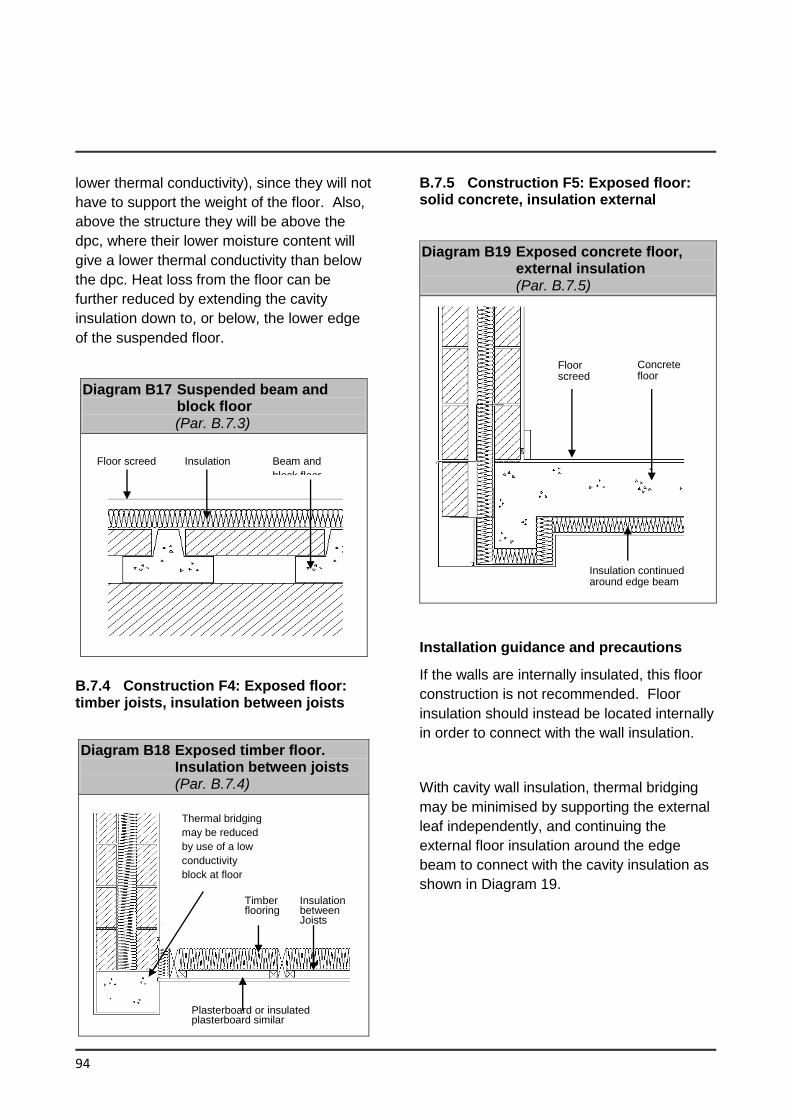
94
lower thermal conductivity), since they will not
have to support the weight of the floor. Also,
above the structure they will be above the
dpc, where their lower moisture content will
give a lower thermal conductivity than below
the dpc. Heat loss from the floor can be
further reduced by extending the cavity
insulation down to, or below, the lower edge
of the suspended floor.
Diagram B17 Suspended beam and block floor (Par. B.7.3)
B.7.4 Construction F4: Exposed floor: timber joists, insulation between joists
Diagram B18 Exposed timber floor. Insulation between joists (Par. B.7.4)
B.7.5 Construction F5: Exposed floor: solid concrete, insulation external
Diagram B19 Exposed concrete floor, external insulation (Par. B.7.5)
Installation guidance and precautions
If the walls are internally insulated, this floor
construction is not recommended. Floor
insulation should instead be located internally
in order to connect with the wall insulation.
With cavity wall insulation, thermal bridging
may be minimised by supporting the external
leaf independently, and continuing the
external floor insulation around the edge
beam to connect with the cavity insulation as
shown in Diagram 19.
Floor screed Insulation Beam and
block floor
Thermal bridging
may be reduced
by use of a low
conductivity
block at floor
Plasterboard or insulated plasterboard similar
Timber flooring
Insulation between Joists
Floor screed
Concrete floor
Insulation continued around edge beam
Appendix C Reference Values for Calculation of MPEPC and MPCPC
95
The following are parameters for the
reference building which has the same size
i.e. same floor area and volume as the
building being assessed. These performance
parameters represent an improvement in the
order of 60% across all buildings with a 20%
renewable energy contribution. This
represents the Nearly Zero Energy Building
performance.
The primary energy consumption and CO2
Emissions per unit floor area calculated for
this reference building are used to calculate
the primary energy performance coefficient
(EPC) and carbon performance coefficient
(CPC) respectively for the building being
assessed. These in turn are compared to the
MPEPC and MPCPC in order to demonstrate
compliance for the dwelling being assessed.
The MPEPC and MPCPC to be achieved
should be 1 and 1.15 respectively.
Table C1 provides the performance
specification for each performance parameter
Table C2 provides a set of linear thermal
transmittance values for thermal bridges for
use with Table C1
Alternative approaches to achieve the
performance specification in Table C1 are
permitted provided they give the same whole
building energy performance when calculated
in Non-domestic Energy Assessment
Procedure (NEAP) as provided by SEAI.
Two different window specifications have
been provided in Table C1 that vary
depending on the dominant form of
daylighting. The generic forms are:
(a) sidelit through vertical windows (offices,
halls of residence etc.). These have 40%
glazing with 10% framing factor (FF);
(b) toplit through rooflights (warehouses,
industrial buildings etc). These are 12%
glazed with 30% framing factor (FF);
The calculation methodology for Renewable
Energy Ratio (RER) is provided in NEAP.
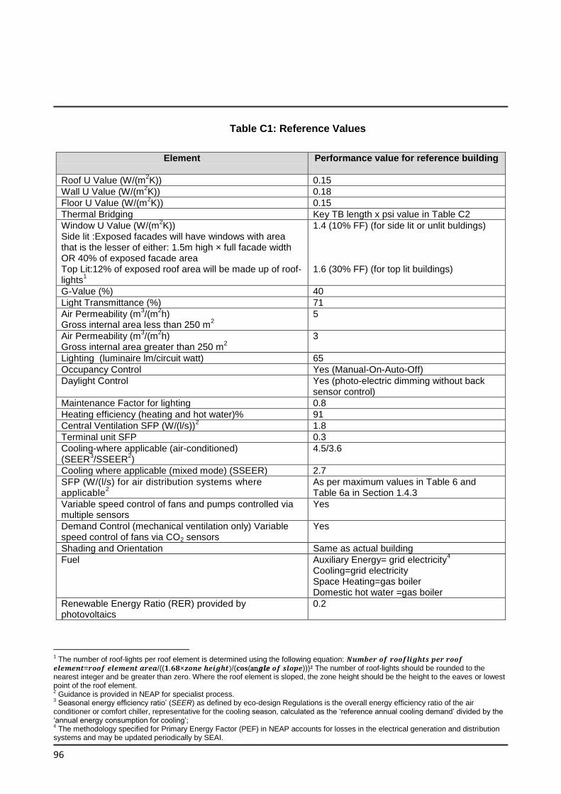
96
Table C1: Reference Values
1 The number of roof-lights per roof element is determined using the following equation: 𝑵𝒖𝒎𝒃𝒆𝒓 𝒐𝒇 𝒓𝒐𝒐𝒇𝒍𝒊𝒈𝒉𝒕𝒔 𝒑𝒆𝒓 𝒓𝒐𝒐𝒇 𝒆𝒍𝒆𝒎𝒆𝒏𝒕=𝒓𝒐𝒐𝒇 𝒆𝒍𝒆𝒎𝒆𝒏𝒕 𝒂𝒓𝒆𝒂/((𝟏.𝟔𝟖×𝒛𝒐𝒏𝒆 𝒉𝒆𝒊𝒈𝒉𝒕)/(𝐜𝐨𝐬(an𝒈𝒍𝒆 𝒐𝒇 𝒔𝒍𝒐𝒑𝒆)))𝟐 The number of roof-lights should be rounded to the nearest integer and be greater than zero. Where the roof element is sloped, the zone height should be the height to the eaves or lowest point of the roof element. 2 Guidance is provided in NEAP for specialist process.
3 Seasonal energy efficiency ratio’ (SEER) as defined by eco-design Regulations is the overall energy efficiency ratio of the air
conditioner or comfort chiller, representative for the cooling season, calculated as the ‘reference annual cooling demand’ divided by the ‘annual energy consumption for cooling’; 4 The methodology specified for Primary Energy Factor (PEF) in NEAP accounts for losses in the electrical generation and distribution
systems and may be updated periodically by SEAI.
Element Performance value for reference building
Roof U Value (W/(m2K)) 0.15
Wall U Value (W/(m2K)) 0.18
Floor U Value (W/(m2K)) 0.15
Thermal Bridging Key TB length x psi value in Table C2
Window U Value (W/(m2K))
Side lit :Exposed facades will have windows with area that is the lesser of either: 1.5m high × full facade width OR 40% of exposed facade area Top Lit:12% of exposed roof area will be made up of roof-lights
1
1.4 (10% FF) (for side lit or unlit buldings) 1.6 (30% FF) (for top lit buildings)
G-Value (%) 40
Light Transmittance (%) 71
Air Permeability (m3/(m
2h)
Gross internal area less than 250 m2
5
Air Permeability (m3/(m
2h)
Gross internal area greater than 250 m2
3
Lighting (luminaire lm/circuit watt) 65
Occupancy Control Yes (Manual-On-Auto-Off)
Daylight Control Yes (photo-electric dimming without back sensor control)
Maintenance Factor for lighting 0.8
Heating efficiency (heating and hot water)% 91
Central Ventilation SFP (W/(l/s))2 1.8
Terminal unit SFP 0.3
Cooling-where applicable (air-conditioned) (SEER
3/SSEER
2)
4.5/3.6
Cooling where applicable (mixed mode) (SSEER) 2.7
SFP (W/(l/s) for air distribution systems where applicable
2
As per maximum values in Table 6 and Table 6a in Section 1.4.3
Variable speed control of fans and pumps controlled via multiple sensors
Yes
Demand Control (mechanical ventilation only) Variable speed control of fans via CO2 sensors
Yes
Shading and Orientation Same as actual building
Fuel Auxiliary Energy= grid electricity4
Cooling=grid electricity Space Heating=gas boiler Domestic hot water =gas boiler
Renewable Energy Ratio (RER) provided by photovoltaics
0.2
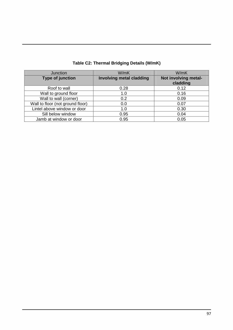
97
Table C2: Thermal Bridging Details (W/mK)
Junction W/mK W/mK
Type of junction Involving metal cladding Not involving metal-cladding
Roof to wall 0.28 0.12
Wall to ground floor 1.0 0.16
Wall to wall (corner) 0.2 0.09
Wall to floor (not ground floor) 0.0 0.07
Lintel above window or door 1.0 0.30
Sill below window 0.95 0.04
Jamb at window or door 0.95 0.05
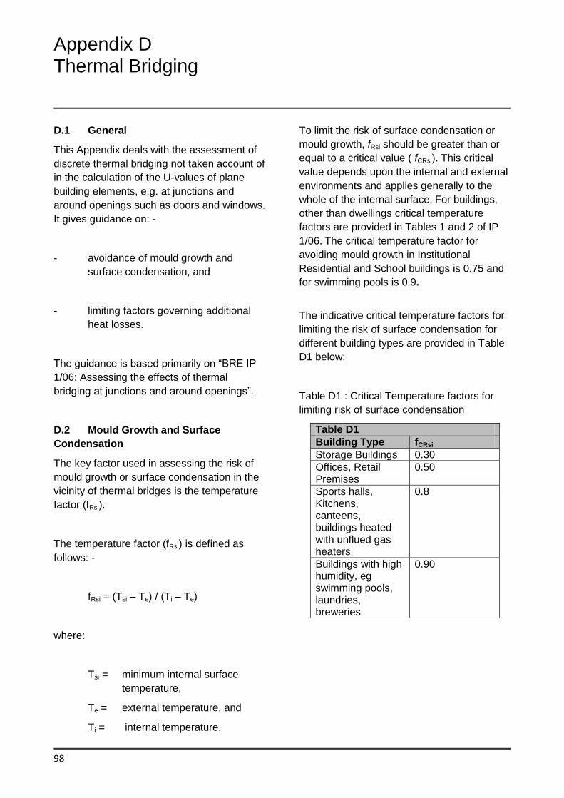
Appendix D Thermal Bridging
98
D.1 General
This Appendix deals with the assessment of
discrete thermal bridging not taken account of
in the calculation of the U-values of plane
building elements, e.g. at junctions and
around openings such as doors and windows.
It gives guidance on: -
- avoidance of mould growth and
surface condensation, and
- limiting factors governing additional
heat losses.
The guidance is based primarily on “BRE IP
1/06: Assessing the effects of thermal
bridging at junctions and around openings”.
D.2 Mould Growth and Surface
Condensation
The key factor used in assessing the risk of
mould growth or surface condensation in the
vicinity of thermal bridges is the temperature
factor (fRsi).
The temperature factor (fRsi) is defined as
follows: -
fRsi = (Tsi – Te) / (Ti – Te)
where:
Tsi = minimum internal surface
temperature,
Te = external temperature, and
Ti = internal temperature.
To limit the risk of surface condensation or
mould growth, fRsi should be greater than or
equal to a critical value ( fCRsi). This critical
value depends upon the internal and external
environments and applies generally to the
whole of the internal surface. For buildings,
other than dwellings critical temperature
factors are provided in Tables 1 and 2 of IP
1/06. The critical temperature factor for
avoiding mould growth in Institutional
Residential and School buildings is 0.75 and
for swimming pools is 0.9.
The indicative critical temperature factors for
limiting the risk of surface condensation for
different building types are provided in Table
D1 below:
Table D1 : Critical Temperature factors for
limiting risk of surface condensation
Table D1
Building Type fCRsi
Storage Buildings 0.30
Offices, Retail Premises
0.50
Sports halls, Kitchens, canteens, buildings heated with unflued gas heaters
0.8
Buildings with high humidity, eg swimming pools, laundries, breweries
0.90
99
D.3 Linear Thermal Transmittance and
Additional Heat Loss
The linear thermal transmittance (ψ)
describes the heat loss associated with a
thermal bridge. This is a property of a
thermal bridge and is the rate of heat flow per
degree per unit length of bridge that is not
accounted for in the U-values of the plane
building elements containing the thermal
bridge. The transmission heat loss
coefficient associated with non-repeating
thermal bridges is calculated as: -
HTB = Σ(Lx ψ) (W/K)
where L is the length of the thermal bridge
over which ψ applies.
D.4 Calculation procedures
The calculation procedure to establish both
temperature factor (fRsi) and the linear thermal
transmittance (ψ) is outlined in BRE IP 1/06.
Details should be assessed in accordance
with the methods described in IS EN ISO
10211:2007. These calculations of two
dimensional or three dimensional heat flow
require the use of numerical modelling
software. To be acceptable, numerical
modelling software should model the
validation examples in IS EN ISO 10211:2007
with results that agree with the stated values
of temperature and heat flow within the
tolerance indicated in the standard for these
examples. Several packages are available
that meet this requirement.
Detailed guidance on decisions regarding
specific input to the modelling software and
the determination of certain quantities from
the output of the software is contained in BRE
Report BR 497 Conventions for calculating
linear thermal transmittance and temperature
factors. This guidance should be followed in
carrying out modelling work so that different
users of the same software package and
users of different software packages can
obtain correct and consistent results.
D.5 Treatment of Thermal Bridging in
NEAP calculation
Heat loss through thermal bridging is taken
account of in the NEAP calculation. The
methods of accounting for heat Loss is
described in 1.3.3. and the NEAP manual.
The following provides for the use of linear
thermal transmission values for Acceptable
Construction Details in NEAP.
Values of ψ can be determined from the
results of numerical modeling, or they can be
derived from measurement. . Values of ψ are
given in Tables D1 to D5 of the Acceptable
Construction Details available on Department
of Housing Planning and Local Government
Acceptable Construction Details have been
assessed to provide a temperature factor i of
0.75. The BRE Certified Thermal Details and
Products Scheme provides temperature
factor for the products/details listed.
Appendix E Specific Fan Power
100
Introduction
This section gives guidance on specifying air
distribution systems for new and existing
buildings to meet relevant energy efficiency
requirements in the Building Regulations.
Scope of Guidance
This guidance applies to the following types
of air distribution system:
Central air conditioning systems
Central mechanical ventilation
systems with heating, cooling or heat
recovery
All central systems not covered by the
above two types
Zonal supply systems where the van
is remote from the zone, such as
ceiling void or roof-mounted units
Zonal extract systems where the fan
is remote from the zone
Local supply and extract ventilation
units such as window, wall or roof
units serving a single area (e.g. toilet
extract)
Other local ventilation units, e.g. fan
coil units and fan assisted variable air
volume (VAV) units
Kitchen extract, fan remote from zone
with grease filter
Gas and oil-fired air heaters installed
within the area to be heated are not
within the scope of this section.
Key Terms
Air conditioning systems means a
combination of components required to
provide a form of air treatment in which
temperature is controlled or can be lowered,
possibly in combination with the control of
ventilation, humidity and air cleanliness.
Ventilation system means a combination of
components required to provide air treatment
in which temperature, ventilation and air
cleanliness are controlled.
Central system means a supply and extract
system which serves the whole or major
zones of the building.
Local unit means an unducted ventilation unit
serving a single area.
Zonal system means a system which serves
a group of rooms forming part of a building,
i.e. a zone where ducting is required.
Demand control is a type of control where the
ventilation rate is controlled by air quality,
moisture, occupancy or some other indicator
of the need for ventilation.
Specific fan power (SFP) of an air distribution
system means the sum of the design circuit-
watts of the system fans that supply air and
exhaust it back outdoors, including losses
through switchgear and design air flow rate
through that system.
For the purposes of this guide, the specific
fan power of an air distribution system should
be calculated according to the procedure set
out in IS EN 13779:2007 Annex D
“Calculation and application of specific fan
power. Calculating the SFP, SFPE, SFPV”
Where
SFP is the specific fan power demand of
the air distribution system ( W/l/s)
Psf is the total fan power of all supply air
fans at the design air flow rate,
including power losses through
switchgear and controls associated
with powering and controlling the fans
(W)
101
Pef is the total fan power of all exhaust air
fans at the design air flow rate
including air flow losses through the
switchgear and controls associated
with powering and controlling the fans
(W)
q is the design air flow rate through the
system, which should be the greater
of either the supply or exhaust air flow
(l/s). Note that for an air handling unit,
q is the largest supply or extract air
flow through the unit.
External system pressure drop means the
total system pressure drop excluding the
pressure drop across the air handling unit.
Air distribution systems in new and
existing buildings
Air distribution systems in new and existing
buildings should meet the following
recommended minimum standards:
(a) air handling systems should be capable
of achieving a specific fan power at
25% of the design flow rate no greater
than that achieved at 100% design flow
rate.
(b) in order to aid commissioning and to
provide flexibility for future changes of
use, reasonable provision would be to
equip with variable speed drives those
fans that are rated at more than 1100W
and which form part of the
environmental control systems,
including smoke control fans used for
control of overheating. The provision is
not applicable to smoke control fans
and similar ventilation systems only
used in abnormal circumstances.
(c) in order to limit air leakage, ventilation
ductwork should be made and
assembled so as to be reasonable
airtight. Ways of meeting this
requirement would be to comply with
the specifications given in:
EN Standards such as IS EN
1507:2006 , ISEN 12237:2003 and IS
EN 13403: 2003.
(d) in order to limit air leakage, air handling
units should be made and assembled
so as to be reasonably airtight. Ways of
meeting this requirement would be to
comply with Class L2 air leakage given
in IS EN 1886:2007.
(e) The specific fan power of air distribution
systems at the design air flow rate
should be no worse than in Table 4 for
new and Table 12 for existing buildings.
Specific fan power is a function of the
system resistance that the fan has to
overcome to provide the required flow
rate. IS EN 13779:2007 Table A8
provides guidance on system pressure
drop. To minimise specific fan power it
is recommended that the ‘low range’ is
used as a design target.
Appendix F Lighting
102
Key Terms
The following definitions apply to lighting:
Daylit space means any space:
(a) within 6 m of a window wall, provided that
the glazing is at least 20% of the internal
area of the window wall or
(b) below rooflights, provided that the glazing
area is at least 10% of the floor area
The normal light transmittance of the glazing
should be at least 70%; if the light
transmittance is below 70% the glazing
should be increased proportionately for the
space to be defined as daylit.
Office area means a space that involves
predominantly desk-based tasks.
Efficacy is used to describe the energy
efficiency of a lamp. It is described by the
amount of light it produces in lumens with
respect to the power it consumes in Watts.
Space classification for control purposes.
Owned space means a space such as a
small room for one or two people who
control the lighting-e.g. a cellular office or
consulting room
Shared space means a multi-occupied
area-e.g. an open-plan office or factory
production area
Temporarily owned space means a space
where people are expected to operate the
lighting controls while they are there-e.g. a
hotel room or meeting room
Occasionally visited space means a space
where people generally stay for a relatively
short period of time when they visit the
space-e.g. a storeroom or toilet
Unowned space means a space where
individual users require lighting but are not
expected to operate the lighting controls -
e.g. a corridor or atrium
Managed space means a space where
lighting is under the control of a
responsible person-e.g. a hotel lounge,
restaurant or shop
Local manual switching means that the
distance on plan from any local switch to the
luminaire it controls should generally be not
more than 6 m, or twice the height of the light
fitting above the floor if this is greater. Where
the space is a daylit space served by side
windows, the perimeter row of lighting should
in general be separately switched.
Photoelectric control is a type of control which
switches or dims lighting in response to the
amount of incoming daylight. Presence
detection is a type of control which switches
the lighting off, or dims it down, after the
space becomes unoccupied but where
switching is done manually.
Lamp lumens means the sum of the average
initial (100 hour) lumen output of all the lamps
in the luminaire.
103
Circuit-watt is the power consumed in lighting
circuits by lamps and, where applicable, their
associated control gear (including
transformers and drivers) and power factor
correction equipment
Lamp lumens per circuit-watt is the total lamp
lumens summed for all luminaires in the
relevant areas of the building, divided by the
total circuit-watts for all the luminaires
LOR is the light output ratio of the luminaire,
which means the ratio of the total light output
of the luminaire under stated practical
conditions to that of the lamp or lamps
contained in the luminaire under reference
conditions
Luminaire lumens per circuit-watt is the (
lamp lumens x LOR) summed for all
luminaires in the relevant areas of the
building divided by the total circuit-watts for
all the luminaires.
LENI (Lighting Energy Numerical Indicator) is
a measure of the performance of lighting in
terms of energy per square meter per year
(kWh/m2/year) based on IS EN 15193:2007
Energy performance of buildings. Energy
requirements for lighting.
An alternative to complying with the efficacy
standards in Table 8 is to follow the Lighting
Energy Numeric Indicator (LENI) method.
The LENI method calculates the performance
of lighting in terms of energy per square
metre per year. The approach described
below must be followed in calculating the
LENI for a lighting scheme. The LENI should
not exceed the lighting energy limit specified
in Table 9 for the given illuminance and hours
run.
Design the lighting
The first step to energy efficient lighting is to
design the lighting installation in a way that
meets all of the users’ needs for the space
under consideration. Recommendations for
appropriate illuminance values and other
lighting requirements may be found in IS EN
12464-1:2011, and in the Society of Light and
Lighting (SLL) Code for Lighting. The SLL
Lighting Handbook provides practical advice
on how to design lighting for a number of
different applications.
Look up the lighting energy limit.
In designing the lighting, a level of
illuminance will have been selected as
necessary for the tasks being done in a
particular area. It is also necessary to
determine how many hours per year the
lighting will be needed. Once both the
illuminance and the hours are known it is
possible to look up the lighting energy limit in
Table 9. For example, an office may be lit to
300 lux and used for 40 hours per week for
39 weeks of the year, giving a total of 1560
hours per year. Values of 1500 hours and
300 lux give a lighting energy limit of 7.70.
Table 9 also gives a day-time (Td ) and night-
time (Tn) hour values which are used in the
calculation of energy consumption.
If display lighting is used, then the lighting
energy limit may be increased by the value
for normal display lighting for the area of the
104
room where the display lighting is being used.
For example, in an entrance area for a
building there may be some display lighting in
a small area around the reception desk but
not in the rest of the area.
Shop windows use a lot of display lighting
and may use up to 192.72 kWh/m2/year if the
window faces a public road, and 96.8kWh/
m2/year if the window is in a shopping centre
that is closed during the night.
Calculate the parasitic energy use (Ep)
If some form of lighting control system is
used, then an allowance needs to be made
for the energy used by the control system,
and the fact that the luminaires take a little
power even if they are dimmed down to give
no light. An allowance of 0.3 W/m2 should be
made for power used in this way. If the whole
lighting system is switched off when the room
is not in use, then the power loss is only
during the hours of use. If the system is left
on all the time then the power loss occurs for
8760 hours per year.
Determine the total power of lighting (P1)
This is the total power in watts consumed by
the luminaires within a space.
Determine the occupancy factor (Fo)
Fo allows for the fact that energy is saved if
an automatic control system detects the
presence or absence of people in a room and
switches off the lights when there is nobody
using the room. If no automatic control is
used then the occupancy factor, Fo =1. If
controls turn off the lights within 20 minutes of
the room being empty, then Fo =0.8.
Determine the factor for daylight (Fd)
Fd allows for the fact that if the lighting is
dimmed down when there is daylight
available, then less energy will be used. If no
daylight linked dimming system is used, then
Fd =1. If the electric lighting dims in response
to daylight being available, then in areas with
adequate daylight Fd =0.8. Adequate
daylight may be found in areas that are within
6m of a window wall or in areas where 10%
or more of the roof is translucent or made up
of rooflights.
Determine the constant illuminance factor
(FC)
When lighting is designed, a maintenance
factor (MF) is used to allow for fact that as the
lighting system ages it produces less light.
This means that on day one the lighting
system is providing more light than needed.
Thus with a constant luminance system, it is
possible to under-run the lighting on day one,
and then slowly increase the power used by
the lighting until the point is reached when
maintenance needs to be carried out by
changing the lamps or cleaning the
luminaires. Systems that control the lighting
in this way have an FC =0.9, and those that do
not have an FC =1.
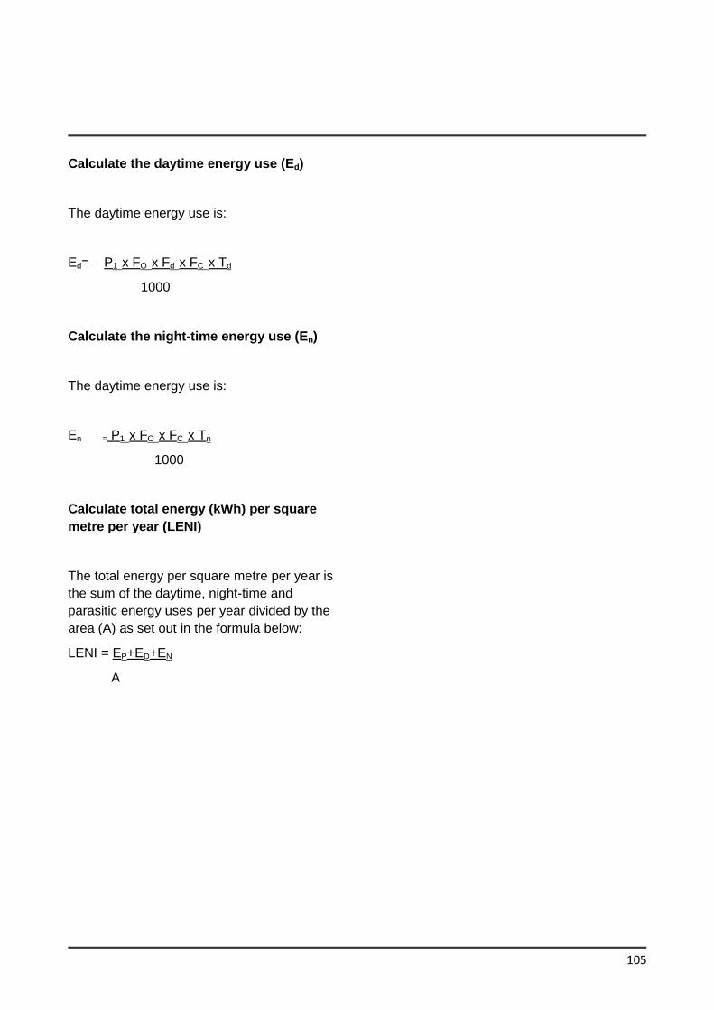
105
Calculate the daytime energy use (Ed)
The daytime energy use is:
Ed= P1 x FO x Fd x FC x Td
1000
Calculate the night-time energy use (En)
The daytime energy use is:
En = P1 x FO x FC x Tn
1000
Calculate total energy (kWh) per square
metre per year (LENI)
The total energy per square metre per year is
the sum of the daytime, night-time and
parasitic energy uses per year divided by the
area (A) as set out in the formula below:
LENI = EP+ED+EN
A
Appendix G: Pipework and Ductwork Insulation
106
Introduction
This section gives guidance on insulating
pipework and ducting serving space heating,
hot water and cooling systems in new and
existing buildings to meet the relevant energy
efficiency requirements in the building
regulations.
The insulation of pipework and ducting is
essential to minimise heating system heat
losses and cooling system heat gains. For
cooling systems , it is also important to
ensure that the risk of condensation is
adequately controlled.
Scope of guidance
The guidance in this section covers insulation
for the following types of pipework and
ductwork serving space heating, domestic hot
water and cooling systems :
pipe work : direct hot water, low,
medium and high temperature
heating, and cooled
ductwork : heated, cooled and dual
purpose heated and cooled.
Insulation of pipes and ducts in new and
existing buildings
Insulation of pipes and ducts serving heating
and cooling systems should meet the
following recommended minimum standards.
The relevant standard for calculating
insulation thickness is I.S. EN ISO
12241:2008 Thermal insulation for building
equipment and industrial installations.
Calculation rules.
(a) Direct hot water and heating pipework
(i) Pipework serving space heating and
hot water systems should be insulated
in all areas outside of the heated
building envelope. In addition, pipes
should be insulated in all voids within
the building envelope and within
spaces which will normally be heated,
if there is a possibility that those
spaces might be maintained at
temperatures different to those
maintained in other zones. The
guiding principles are that control
should be maximised and that heat
loss from uninsulated pipes should
only be permitted where the heat can
be demonstrated as “always useful”.
(ii) In order to demonstrate compliance,
the heat losses shown in Table G.1 for
different pipe sizes and temperatures
should not be exceeded.
(b) Cooling pipework
(i) Cooling pipework should be insulated
along its whole length in order to
provide the necessary means of
limiting heat gain. Control should be
maximised and heat gain to
uninsulated pipes should only be
permitted where the proportion of the
cooling load relating to distribution
pipework is proven to be less than 1%
of the total load.
(ii) In order to demonstrate compliance, the
heat gains in Table G.2 for different
pipe sizes and temperatures should not
be exceeded.
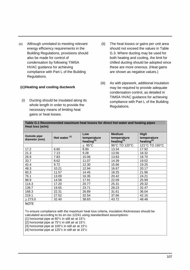
107
(iii) Although unrelated to meeting relevant
energy efficiency requirements in the
Building Regulations, provisions should
also be made for control of
condensation by following TIMSA
HVAC guidance for achieving
compliance with Part L of the Building
Regulations.
(c) Heating and cooling ductwork
(i) Ducting should be insulated along its
whole length in order to provide the
necessary means of limiting heat
gains or heat losses.
(ii) The heat losses or gains per unit area
should not exceed the values in Table
G.3. Where ducting may be used for
both heating and cooling, the limit for
chilled ducting should be adopted since
these are more onerous. (Heat gains
are shown as negative values.)
(iii) As with pipework, additional insulation
may be required to provide adequate
condensation control, as detailed in
TIMSA HVAC guidance for achieving
compliance with Part L of the Building
Regulations.
Table G.1 Recommended maximum heat losses for direct hot water and heating pipes Heat loss (w/m)
Outside pipe diameter (mm)
Hot water (1)
Low temperature heating
(2)
Medium temperature heating
(3)
High temperature heating
(4)
< 95°C 96°C TO 120°C 121°C TO 150°C
17.2 6.60 8.90 13.34 17.92
21.3 7.13 9.28 13.56 18.32
26.9 7.83 10.06 13.83 18.70
33.7 8.62 11.07 14.39 19.02
42.4 9.72 12.30 15.66 19.25
48.3 10.21 12.94 16.67 20.17
60.3 11.57 14.45 18.25 21.96
76.1 13.09 16.35 20.42 24.21
88.9 14.58 17.91 22.09 25.99
114.3 17.20 20.77 25.31 29.32
139.7 19.65 23.71 28.23 32.47
168.3 22.31 26.89 31.61 36.04
219.1 27.52 32.54 37.66 42.16
> 273.0 32.40 38.83 43.72 48.48
NOTE
To ensure compliance with the maximum heat loss criteria, insulation thicknesses should be calculated according to bs en iso 12241 using standardised assumptions: [1] horizontal pipe at 60°c in still air at 15°c [2] horizontal pipe at 75°c in still air at 15°c [3] horizontal pipe at 100°c in still air at 15°c [4] horizontal pipe at 125°c in still air at 15°c
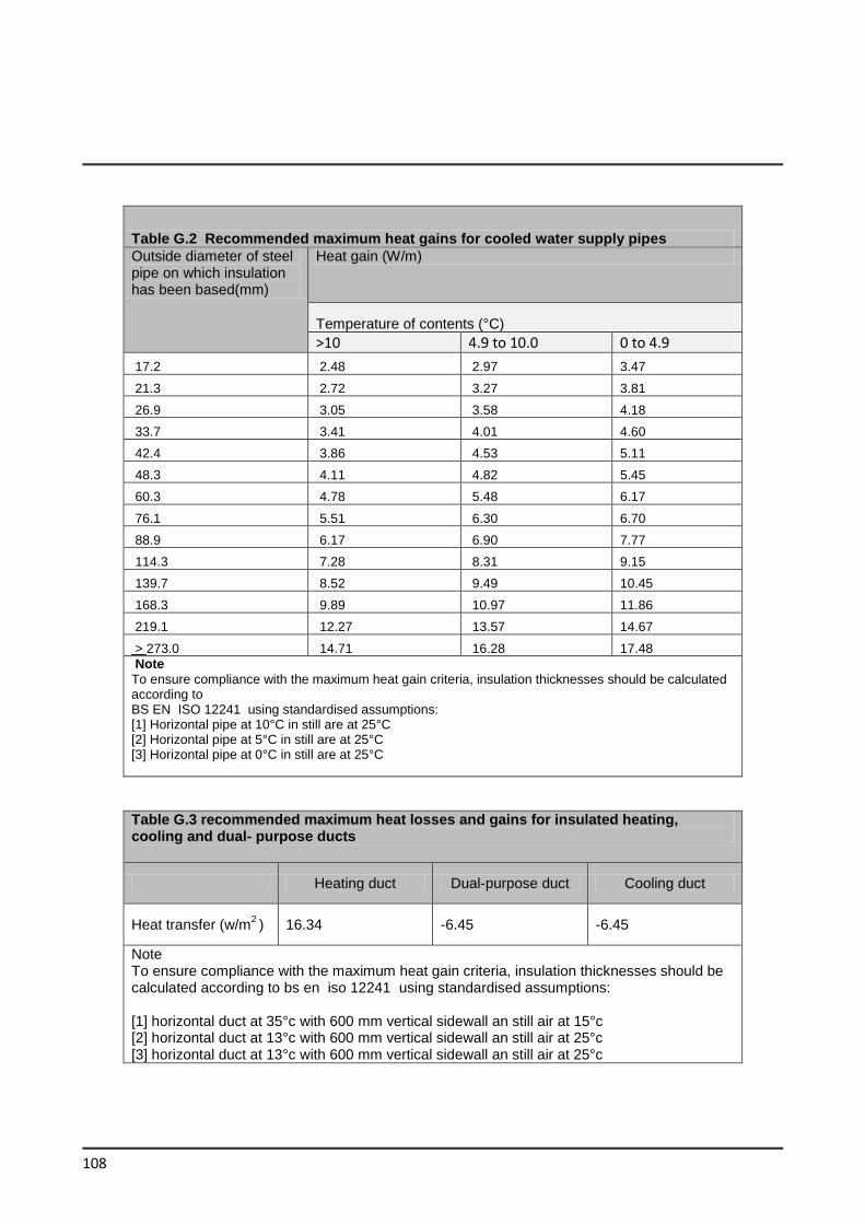
108
Table G.2 Recommended maximum heat gains for cooled water supply pipes
Outside diameter of steel pipe on which insulation has been based(mm)
Heat gain (W/m)
Temperature of contents (°C)
>10 4.9 to 10.0 0 to 4.9
17.2 2.48 2.97 3.47
21.3 2.72 3.27 3.81
26.9 3.05 3.58 4.18
33.7 3.41 4.01 4.60
42.4 3.86 4.53 5.11
48.3 4.11 4.82 5.45
60.3 4.78 5.48 6.17
76.1 5.51 6.30 6.70
88.9 6.17 6.90 7.77
114.3 7.28 8.31 9.15
139.7 8.52 9.49 10.45
168.3 9.89 10.97 11.86
219.1 12.27 13.57 14.67
> 273.0 14.71 16.28 17.48
Note
To ensure compliance with the maximum heat gain criteria, insulation thicknesses should be calculated according to BS EN ISO 12241 using standardised assumptions: [1] Horizontal pipe at 10°C in still are at 25°C [2] Horizontal pipe at 5°C in still are at 25°C [3] Horizontal pipe at 0°C in still are at 25°C
Table G.3 recommended maximum heat losses and gains for insulated heating, cooling and dual- purpose ducts
Heating duct Dual-purpose duct Cooling duct
Heat transfer (w/m2 )
16.34 -6.45 -6.45
Note To ensure compliance with the maximum heat gain criteria, insulation thicknesses should be calculated according to bs en iso 12241 using standardised assumptions: [1] horizontal duct at 35°c with 600 mm vertical sidewall an still air at 15°c [2] horizontal duct at 13°c with 600 mm vertical sidewall an still air at 25°c [3] horizontal duct at 13°c with 600 mm vertical sidewall an still air at 25°c
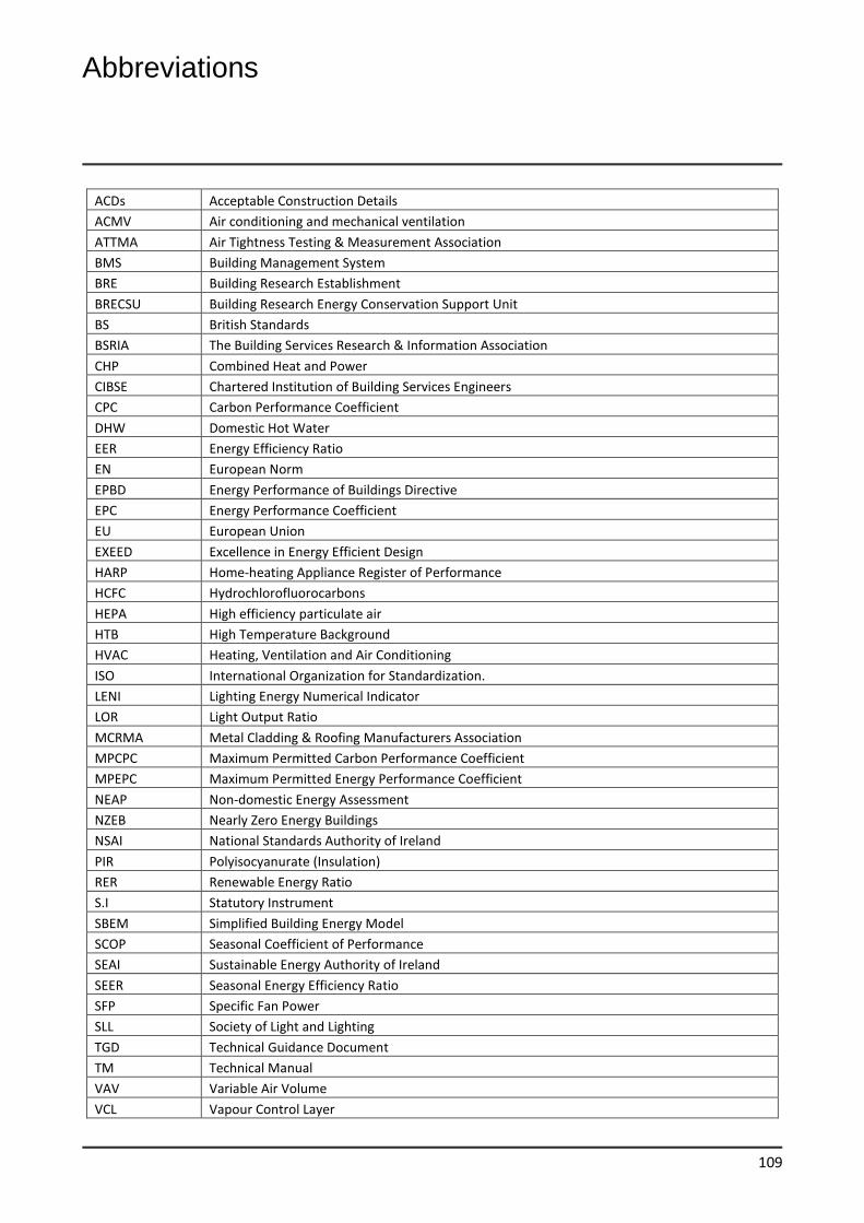
Abbreviations
109
ACDs Acceptable Construction Details
ACMV Air conditioning and mechanical ventilation
ATTMA Air Tightness Testing & Measurement Association
BMS Building Management System
BRE Building Research Establishment
BRECSU Building Research Energy Conservation Support Unit
BS British Standards
BSRIA The Building Services Research & Information Association
CHP Combined Heat and Power
CIBSE Chartered Institution of Building Services Engineers
CPC Carbon Performance Coefficient
DHW Domestic Hot Water
EER Energy Efficiency Ratio
EN European Norm
EPBD Energy Performance of Buildings Directive
EPC Energy Performance Coefficient
EU European Union
EXEED Excellence in Energy Efficient Design
HARP Home-heating Appliance Register of Performance
HCFC Hydrochlorofluorocarbons
HEPA High efficiency particulate air
HTB High Temperature Background
HVAC Heating, Ventilation and Air Conditioning
ISO International Organization for Standardization.
LENI Lighting Energy Numerical Indicator
LOR Light Output Ratio
MCRMA Metal Cladding & Roofing Manufacturers Association
MPCPC Maximum Permitted Carbon Performance Coefficient
MPEPC Maximum Permitted Energy Performance Coefficient
NEAP Non-domestic Energy Assessment
NZEB Nearly Zero Energy Buildings
NSAI National Standards Authority of Ireland
PIR Polyisocyanurate (Insulation)
RER Renewable Energy Ratio
S.I Statutory Instrument
SBEM Simplified Building Energy Model
SCOP Seasonal Coefficient of Performance
SEAI Sustainable Energy Authority of Ireland
SEER Seasonal Energy Efficiency Ratio
SFP Specific Fan Power
SLL Society of Light and Lighting
TGD Technical Guidance Document
TM Technical Manual
VAV Variable Air Volume
VCL Vapour Control Layer
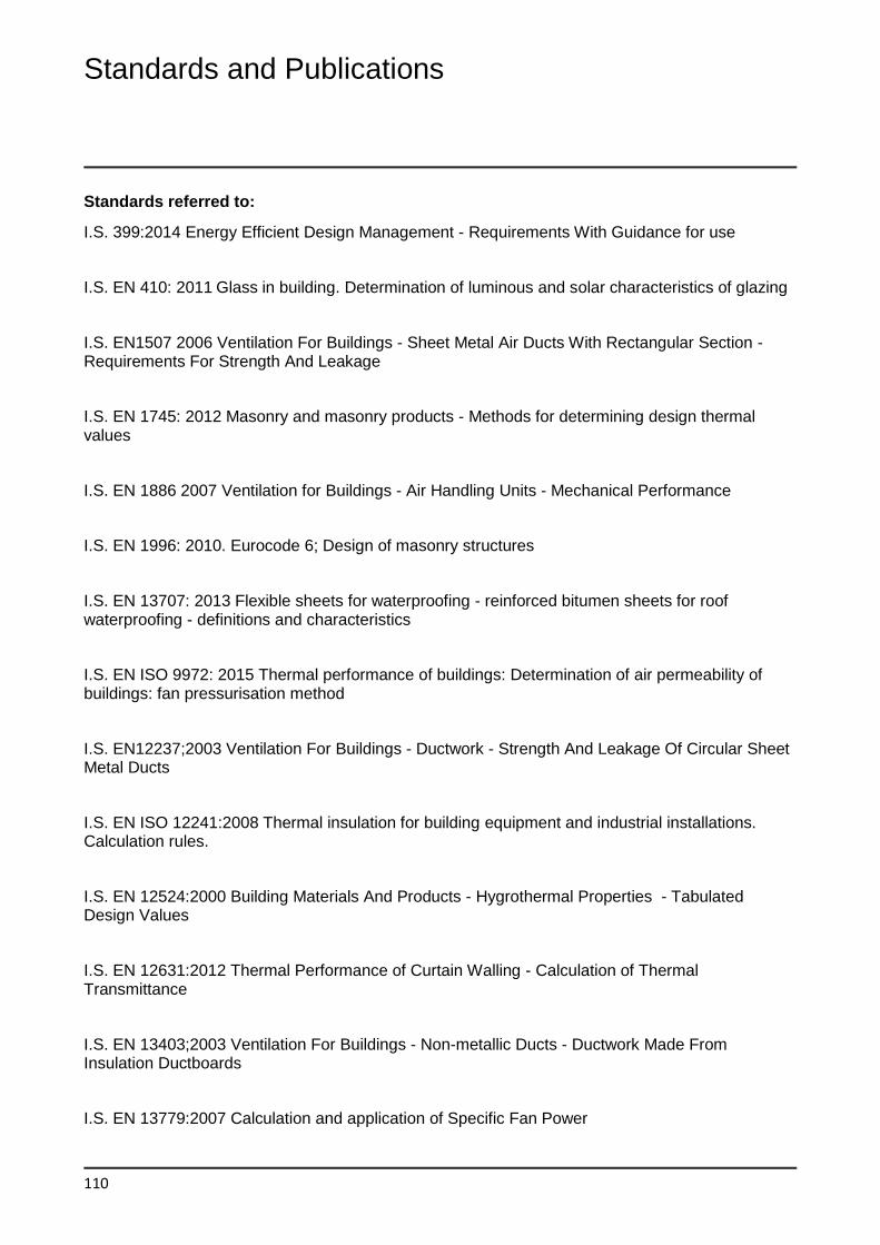
Standards and Publications
110
Standards referred to:
I.S. 399:2014 Energy Efficient Design Management - Requirements With Guidance for use
I.S. EN 410: 2011 Glass in building. Determination of luminous and solar characteristics of glazing
I.S. EN1507 2006 Ventilation For Buildings - Sheet Metal Air Ducts With Rectangular Section - Requirements For Strength And Leakage
I.S. EN 1745: 2012 Masonry and masonry products - Methods for determining design thermal values
I.S. EN 1886 2007 Ventilation for Buildings - Air Handling Units - Mechanical Performance
I.S. EN 1996: 2010. Eurocode 6; Design of masonry structures
I.S. EN 13707: 2013 Flexible sheets for waterproofing - reinforced bitumen sheets for roof waterproofing - definitions and characteristics
I.S. EN ISO 9972: 2015 Thermal performance of buildings: Determination of air permeability of buildings: fan pressurisation method
I.S. EN12237;2003 Ventilation For Buildings - Ductwork - Strength And Leakage Of Circular Sheet Metal Ducts
I.S. EN ISO 12241:2008 Thermal insulation for building equipment and industrial installations. Calculation rules.
I.S. EN 12524:2000 Building Materials And Products - Hygrothermal Properties - Tabulated Design Values
I.S. EN 12631:2012 Thermal Performance of Curtain Walling - Calculation of Thermal Transmittance
I.S. EN 13403;2003 Ventilation For Buildings - Non-metallic Ducts - Ductwork Made From Insulation Ductboards
I.S. EN 13779:2007 Calculation and application of Specific Fan Power
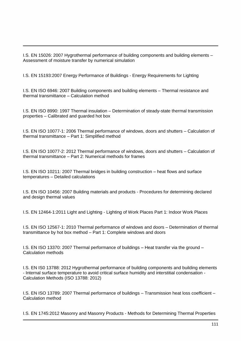
111
I.S. EN 15026: 2007 Hygrothermal performance of building components and building elements – Assessment of moisture transfer by numerical simulation
I.S. EN 15193:2007 Energy Performance of Buildings - Energy Requirements for Lighting
I.S. EN ISO 6946: 2007 Building components and building elements – Thermal resistance and thermal transmittance – Calculation method
I.S. EN ISO 8990: 1997 Thermal insulation – Determination of steady-state thermal transmission properties – Calibrated and guarded hot box
I.S. EN ISO 10077-1: 2006 Thermal performance of windows, doors and shutters – Calculation of thermal transmittance – Part 1: Simplified method
I.S. EN ISO 10077-2: 2012 Thermal performance of windows, doors and shutters – Calculation of thermal transmittance – Part 2: Numerical methods for frames
I.S. EN ISO 10211: 2007 Thermal bridges in building construction – heat flows and surface temperatures – Detailed calculations
I.S. EN ISO 10456: 2007 Building materials and products - Procedures for determining declared and design thermal values
I.S. EN 12464-1:2011 Light and Lighting - Lighting of Work Places Part 1: Indoor Work Places
I.S. EN ISO 12567-1: 2010 Thermal performance of windows and doors – Determination of thermal transmittance by hot box method – Part 1: Complete windows and doors
I.S. EN ISO 13370: 2007 Thermal performance of buildings – Heat transfer via the ground – Calculation methods
I.S. EN IS0 13788: 2012 Hygrothermal performance of building components and building elements - Internal surface temperature to avoid critical surface humidity and interstitial condensation - Calculation Methods (ISO 13788: 2012)
I.S. EN ISO 13789: 2007 Thermal performance of buildings – Transmission heat loss coefficient – Calculation method
I.S. EN 1745:2012 Masonry and Masonry Products - Methods for Determining Thermal Properties
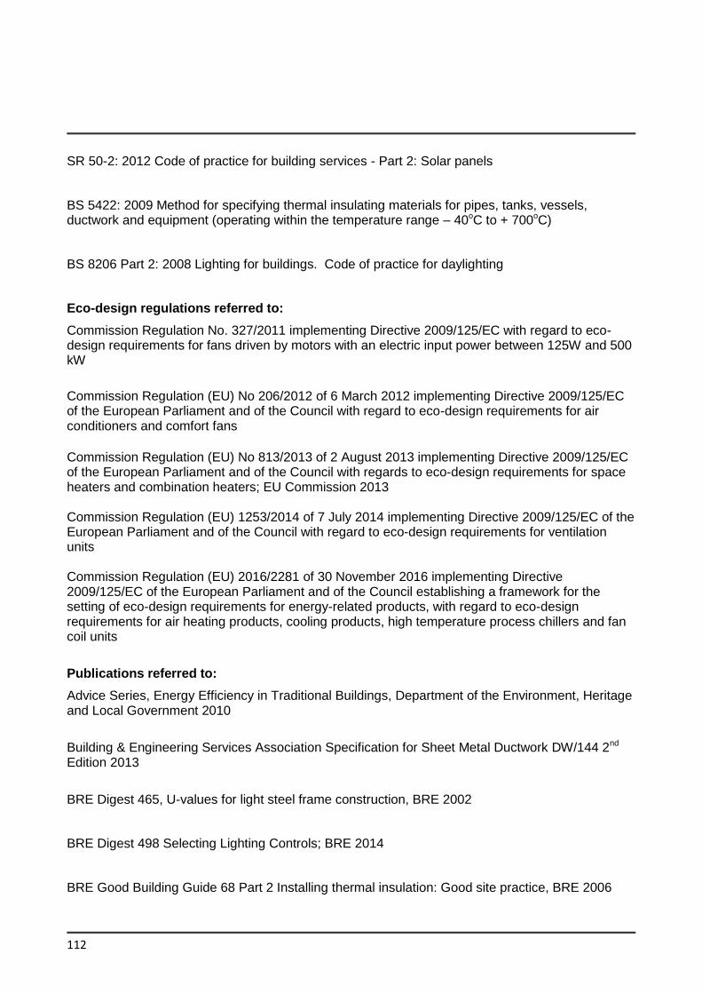
112
SR 50-2: 2012 Code of practice for building services - Part 2: Solar panels
BS 5422: 2009 Method for specifying thermal insulating materials for pipes, tanks, vessels, ductwork and equipment (operating within the temperature range – 40oC to + 700oC)
BS 8206 Part 2: 2008 Lighting for buildings. Code of practice for daylighting
Eco-design regulations referred to:
Commission Regulation No. 327/2011 implementing Directive 2009/125/EC with regard to eco-design requirements for fans driven by motors with an electric input power between 125W and 500 kW
Commission Regulation (EU) No 206/2012 of 6 March 2012 implementing Directive 2009/125/EC of the European Parliament and of the Council with regard to eco-design requirements for air conditioners and comfort fans
Commission Regulation (EU) No 813/2013 of 2 August 2013 implementing Directive 2009/125/EC of the European Parliament and of the Council with regards to eco-design requirements for space heaters and combination heaters; EU Commission 2013 Commission Regulation (EU) 1253/2014 of 7 July 2014 implementing Directive 2009/125/EC of the European Parliament and of the Council with regard to eco-design requirements for ventilation units Commission Regulation (EU) 2016/2281 of 30 November 2016 implementing Directive 2009/125/EC of the European Parliament and of the Council establishing a framework for the setting of eco-design requirements for energy-related products, with regard to eco-design requirements for air heating products, cooling products, high temperature process chillers and fan coil units
Publications referred to:
Advice Series, Energy Efficiency in Traditional Buildings, Department of the Environment, Heritage and Local Government 2010
Building & Engineering Services Association Specification for Sheet Metal Ductwork DW/144 2nd Edition 2013
BRE Digest 465, U-values for light steel frame construction, BRE 2002
BRE Digest 498 Selecting Lighting Controls; BRE 2014
BRE Good Building Guide 68 Part 2 Installing thermal insulation: Good site practice, BRE 2006
113
BRE Information Paper 1/06 Assessing the effects of thermal bridging at junctions and around openings, BRE 2006
BRE Information Paper 10/02, Metal cladding: assessing the thermal performance of built-up systems using ‘Z’ spacers, BRE 2002
BRE Report BR 262, Thermal Insulation: avoiding risks, BRE 2002
BRE Report BR 443, Conventions for U-value calculations, BRE 2006
BRE Report BR 497, Conventions for calculating linear thermal transmittance and temperature factors, BRE 2016
BSRIA Guide BG 8/2004 Free Cooling Systems; BSRIA 2004
BSRIA BG 47/2013 Designing and Constructing for Airtightness; BSRIA 2013
BSRIA Job Book A project framework for engineering services BG1/2009;BSRIA 2009
CIBSE Guide A: Environmental design - Section 3: Thermal properties of buildings and components, CIBSE 2016 8th Edition
CIBSE Guide AM 13 Mixed Mode Ventilation; CIBSE 2000
CIBSE Guide H: Building Control Systems; CIBSE 2009 2nd Edition
CIBSE Lighting Guide (LG10); CIBSE 2014
CIBSE Manual AM 12 Combined Heat and Power in Buildings; CIBSE 2013
CIBSE SLL Code for Lighting; CIBSE 2012
CIBSE TM 23: Testing buildings for air leakage, CIBSE 2000
CIBSE TM52: The Limits of Thermal Comfort: Avoiding Overheating in European Buildings; CIBSE 2013
114
HVCA Ductwork Specification DW/143 Practical guide to ductwork leakage testing. Heating and Ventilating Contractors' Association; 2000 5th edition
General Information, Report 41 (GIR041) Variable flow control, General Information; CIBSE 1996
Limiting Thermal Bridging and Air Infiltration – Acceptable Construction Details to TGD L 2011 (www.housing.gov.ie)
MCRMA Technical Paper No. 14, Guidance for the design of metal roofing and cladding to comply with Approved Document L2: 2001, The Metal Cladding and Roofing Manufacturers Association 2002
Measuring air permeability in the air envelopes of buildings (non-dwellings), Technical Standard L2, ATTMA 2010
Non Domestic Energy Assessment Procedure (NEAP), SEAI (www.seai.ie)
Planning Guidelines No. 9: Architectural Heritage Protection - Guidelines for Planning Authorities, Department of the Environment, Heritage and Local Government 2004
Society of Light and Lighting (SLL) Code for Lighting. SLL/CIBSE 2012
Steel Construction Institute Technical Information Sheet 312, Metal cladding: U-value calculation - assessing thermal performance of built-up metal roof and wall cladding systems using rail and bracket spacers, The Steel Construction Institute 2002
Steel Construction Institute Publication 380 2008 Avoidance of Thermal Bridging in Steel Construction
Steel Construction Institute Publication P410 Thermal Bridging in Steel Construction
Sustainable Energy Authority of Ireland (SEAI) Guide to Relative Humidity in Data Centres
TIMSA guidance for achieving compliance with Part L of the Building Regulations;TIMSA 2006 edition- revised February 2008)
115
Other useful standards and Publications
BRE Report BR 364, Solar shading of buildings, BRE 1999
I.S. EN 303-5: 2012 Heating boilers - Heating boilers for solid fuels, hand and automatically stoked, nominal heat output of up to 300 kw - Terminology requirements, testing and marking
I.S. EN ISO 9806-1: 2013 Test methods for solar collectors
I.S. EN 12664: 2001 Thermal performance of building materials and products – Determination of thermal resistance by means of guarded hot plate and heat flow meters method – Dry and moist products of low and medium thermal resistance
I.S. EN 12667: 2001 Thermal performance of building materials and products – Determination of thermal resistance by means of guarded hot plate and heat flow meters method – Products of high and medium thermal resistance
I.S. EN 12828: 2012 Heating systems in buildings - Design for water-based heating systems
I.S. EN 12939: 2000 Thermal performance of building materials and products – Determination of thermal resistance by means of guarded hot plate and heat flow meters method – Thick products of high and medium thermal resistance
I.S. EN 12975-1: 2006 Thermal solar systems and components - Solar collectors - Part 1: General requirements
I.S. EN 12975-2: 2006 Thermal Solar Systems And Components - Solar Collectors Part 2: Test Methods
I.S. EN 12976-1: 2017 Thermal solar systems and components - Factory made systems - Part 1: General requirements
I.S. EN 12976-2: 2017 Thermal solar systems and components - Factory made systems - Part 2: Test methods
I.S. EN 15270: 2007 Pellet burners for small heating boilers - Definitions, requirements, testing, marking
I.S. EN 12977-1: 2012 Thermal solar systems and components - Custom built systems - Part 1: General requirements
I.S. EN 12977-2: 2012 Thermal solar systems and components - Custom built systems - Part 2: Test method

Printed on recycled paper containing aminimum of 75% post-consumer waste