Embed Size (px)
Citation preview
© Big Switch Networks 1
Core and Pod Data Center Design Overview The Core and Pod data center design used by most hyperscale data centers is a dramatically more modern approach than traditional data center network design, and is starting to be understood by a broader community of enterprise and service provider architects.
As opposed to traditional Core-‐Aggregation-‐Edge data center designs that optimized for north-‐south bandwidth, Core and Pod designs optimize for data center agility. They start from the core economic assumptions that data center capacity will be built out over time rather than all at once, and during that time period there will be significant technology advances in the price/performance of compute, storage and networking hardware. Most of the hyperscale data centers that we see prove this point – despite their massive scale, their hardware is (on average) much newer than traditionally designed data centers.
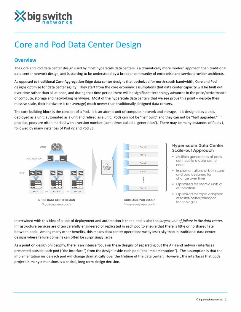
The core building block is the concept of a Pod. It is an atomic unit of compute, network and storage. It is designed as a unit, deployed as a unit, automated as a unit and retired as a unit. Pods can not be “half built” and they can not be “half upgraded.” In practice, pods are often marked with a version number (sometimes called a ‘generation’). There may be many instances of Pod v1, followed by many instances of Pod v2 and Pod v3.
Intertwined with this idea of a unit of deployment and automation is that a pod is also the largest unit of failure in the data center. Infrastructure services are often carefully engineered or replicated in each pod to ensure that there is little or no shared fate between pods. Among many other benefits, this makes data center operations vastly less risky than in traditional data center designs where failure domains can often be surprisingly large.
As a point on design philosophy, there is an intense focus on these designs of separating out the APIs and network interfaces presented outside each pod (“the interface”) from the design inside each pod (“the implementation”). The assumption is that the implementation inside each pod will change dramatically over the lifetime of the data center. However, the interfaces that pods project in many dimensions is a critical, long term design decision.
RACK M RACK N RACK 1
CORE
AGGREGATION
EDGE
N-TIER DATA CENTER DESIGN
(Traditional Approach)
Hyper-scale Data Center Scale-out Approach ! Multiple generations of pods
connect to a data center core
! Implementations of both core and pod designed for change over time
! Optimized for atomic units of automation
! Optimized for rapid adoption of faster/better/cheaper technologies
CORE-AND-POD DESIGN
(Hyper-scale Approach)
Pod v1
Pod v2
Pod vN
DC ROUTED CORE
Pod v2
Pod v2
Core and Pod Data Center Design
© Big Switch Networks 2
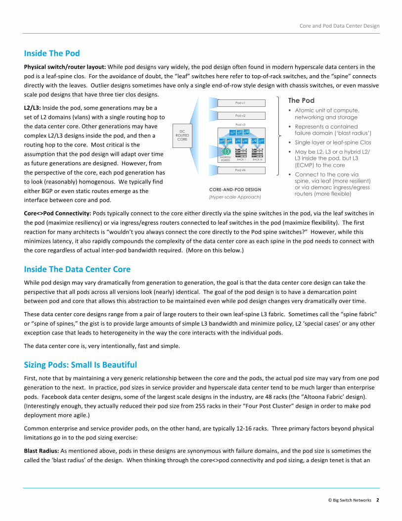
Inside The Pod Physical switch/router layout: While pod designs vary widely, the pod design often found in modern hyperscale data centers in the pod is a leaf-‐spine clos. For the avoidance of doubt, the “leaf” switches here refer to top-‐of-‐rack switches, and the “spine” connects directly with the leaves. Outlier designs sometimes have only a single end-‐of-‐row style design with chassis switches, or even massive scale pod designs that have three tier clos designs.
L2/L3: Inside the pod, some generations may be a set of L2 domains (vlans) with a single routing hop to the data center core. Other generations may have complex L2/L3 designs inside the pod, and then a routing hop to the core. Most critical is the assumption that the pod design will adapt over time as future generations are designed. However, from the perspective of the core, each pod generation has to look (reasonably) homogenous. We typically find either BGP or even static routes emerge as the interface between core and pod.
Core<>Pod Connectivity: Pods typically connect to the core either directly via the spine switches in the pod, via the leaf switches in the pod (maximize resiliency) or via ingress/egress routers connected to leaf switches in the pod (maximize flexibility). The first reaction for many architects is “wouldn’t you always connect the core directly to the Pod spine switches?” However, while this minimizes latency, it also rapidly compounds the complexity of the data center core as each spine in the pod needs to connect with the core regardless of actual inter-‐pod bandwidth required. (More on this below.)
Inside The Data Center Core While pod design may vary dramatically from generation to generation, the goal is that the data center core design can take the perspective that all pods across all versions look (nearly) identical. The goal of the pod design is to have a demarcation point between pod and core that allows this abstraction to be maintained even while pod design changes very dramatically over time.
These data center core designs range from a pair of large routers to their own leaf-‐spine L3 fabric. Sometimes call the “spine fabric” or “spine of spines,” the gist is to provide large amounts of simple L3 bandwidth and minimize policy, L2 ‘special cases’ or any other exception case that leads to heterogeneity in the way the core interacts with the individual pods.
The data center core is, very intentionally, fast and simple.
Sizing Pods: Small Is Beautiful First, note that by maintaining a very generic relationship between the core and the pods, the actual pod size may vary from one pod generation to the next. In practice, pod sizes in service provider and hyperscale data center tend to be much larger than enterprise pods. Facebook data center designs, some of the largest scale designs in the industry, are 48 racks (the “Altoona Fabric’ design). (Interestingly enough, they actually reduced their pod size from 255 racks in their “Four Post Cluster” design in order to make pod deployment more agile.)
Common enterprise and service provider pods, on the other hand, are typically 12-‐16 racks. Three primary factors beyond physical limitations go in to the pod sizing exercise:
Blast Radius: As mentioned above, pods in these designs are synonymous with failure domains, and the pod size is sometimes the called the ‘blast radius’ of the design. When thinking through the core<>pod connectivity and pod sizing, a design tenet is that an
CORE-AND-POD DESIGN
(Hyper-scale Approach)
Pod v1
Pod v2
Pod vN
The Pod ! Atomic unit of compute,
networking and storage
! Represents a contained failure domain (‘blast radius’)
! Single layer or leaf-spine Clos
! May be L2, L3 or a hybrid L2/L3 inside the pod, but L3 (ECMP) to the core
! Connect to the core via spine, via leaf (more resilient) or via demarc ingress/egress routers (more flexible)
RACK N RACK 1 INGRESS/EGRESS
Pod v3
DC ROUTED CORE
Core and Pod Data Center Design
© Big Switch Networks 3
unexpected, cascading failure be contained within the pod. Note that with current server technology and conservative provisioning of 25 VMs per RU, a 16 rack pod is a 16,000 VM failure domain. This is, by most standards, a large enough pod.
Simplified Automation: The two largest contributors to code complexity in network automation are a) variation in topology, and b) test-‐ability. By keeping pods small and automating each pod as a unit, automation developers know *exactly* the topology that the code will assume as opposed to automating an entire data center or very large pod whose topology may evolve over time. A small pod is also vastly more practical to replicate in the lab to test automation code before running it in production.
‘80% Full Pod’ Problem: While the first two factors would push to smaller pods, the ‘80% Full Pod’ problem occurs when a specific enterprise application housed in a pod needs more capacity to grow, yet the pod is already almost full. Do you you split the application between two pods, or move the application to a new pod? Neither path is attractive, and the answer is case dependent. However, we can say with certainty this happens more often with small pods than large ones. In practice, this is an important but unknowable consideration at design time and is usually an operational trade-‐off vs the simplified automation of smaller pods.
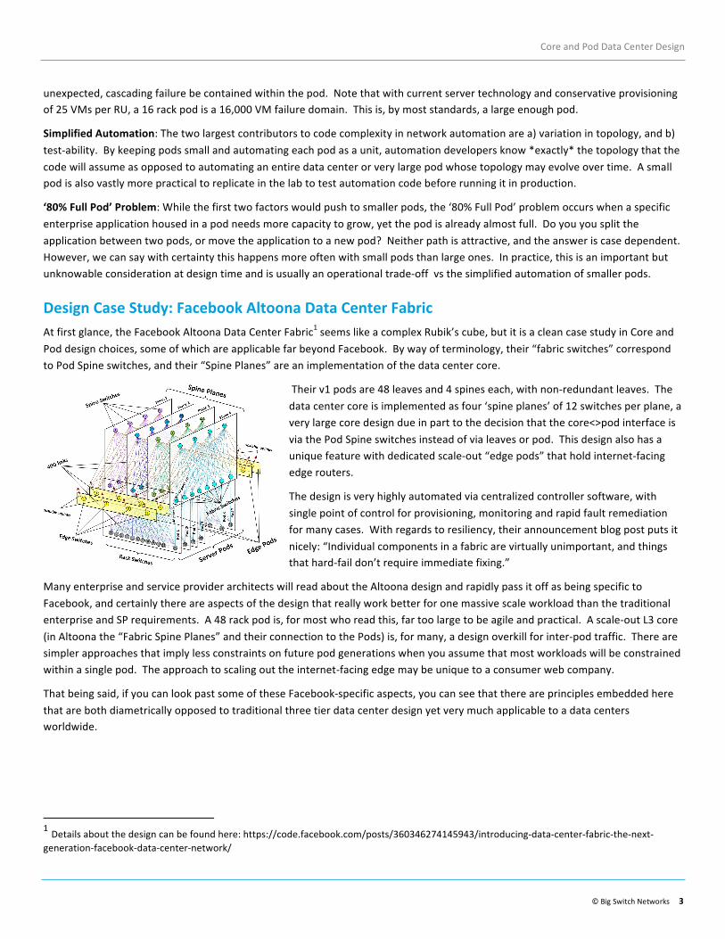
Design Case Study: Facebook Altoona Data Center Fabric At first glance, the Facebook Altoona Data Center Fabric1 seems like a complex Rubik’s cube, but it is a clean case study in Core and Pod design choices, some of which are applicable far beyond Facebook. By way of terminology, their “fabric switches” correspond to Pod Spine switches, and their “Spine Planes” are an implementation of the data center core.
Their v1 pods are 48 leaves and 4 spines each, with non-‐redundant leaves. The data center core is implemented as four ‘spine planes’ of 12 switches per plane, a very large core design due in part to the decision that the core<>pod interface is via the Pod Spine switches instead of via leaves or pod. This design also has a unique feature with dedicated scale-‐out “edge pods” that hold internet-‐facing edge routers.
The design is very highly automated via centralized controller software, with single point of control for provisioning, monitoring and rapid fault remediation for many cases. With regards to resiliency, their announcement blog post puts it nicely: “Individual components in a fabric are virtually unimportant, and things that hard-‐fail don’t require immediate fixing.”
Many enterprise and service provider architects will read about the Altoona design and rapidly pass it off as being specific to Facebook, and certainly there are aspects of the design that really work better for one massive scale workload than the traditional enterprise and SP requirements. A 48 rack pod is, for most who read this, far too large to be agile and practical. A scale-‐out L3 core (in Altoona the “Fabric Spine Planes” and their connection to the Pods) is, for many, a design overkill for inter-‐pod traffic. There are simpler approaches that imply less constraints on future pod generations when you assume that most workloads will be constrained within a single pod. The approach to scaling out the internet-‐facing edge may be unique to a consumer web company.
That being said, if you can look past some of these Facebook-‐specific aspects, you can see that there are principles embedded here that are both diametrically opposed to traditional three tier data center design yet very much applicable to a data centers worldwide.
1 Details about the design can be found here: https://code.facebook.com/posts/360346274145943/introducing-‐data-‐center-‐fabric-‐the-‐next-‐generation-‐facebook-‐data-‐center-‐network/
Core and Pod Data Center Design
© Big Switch Networks 4
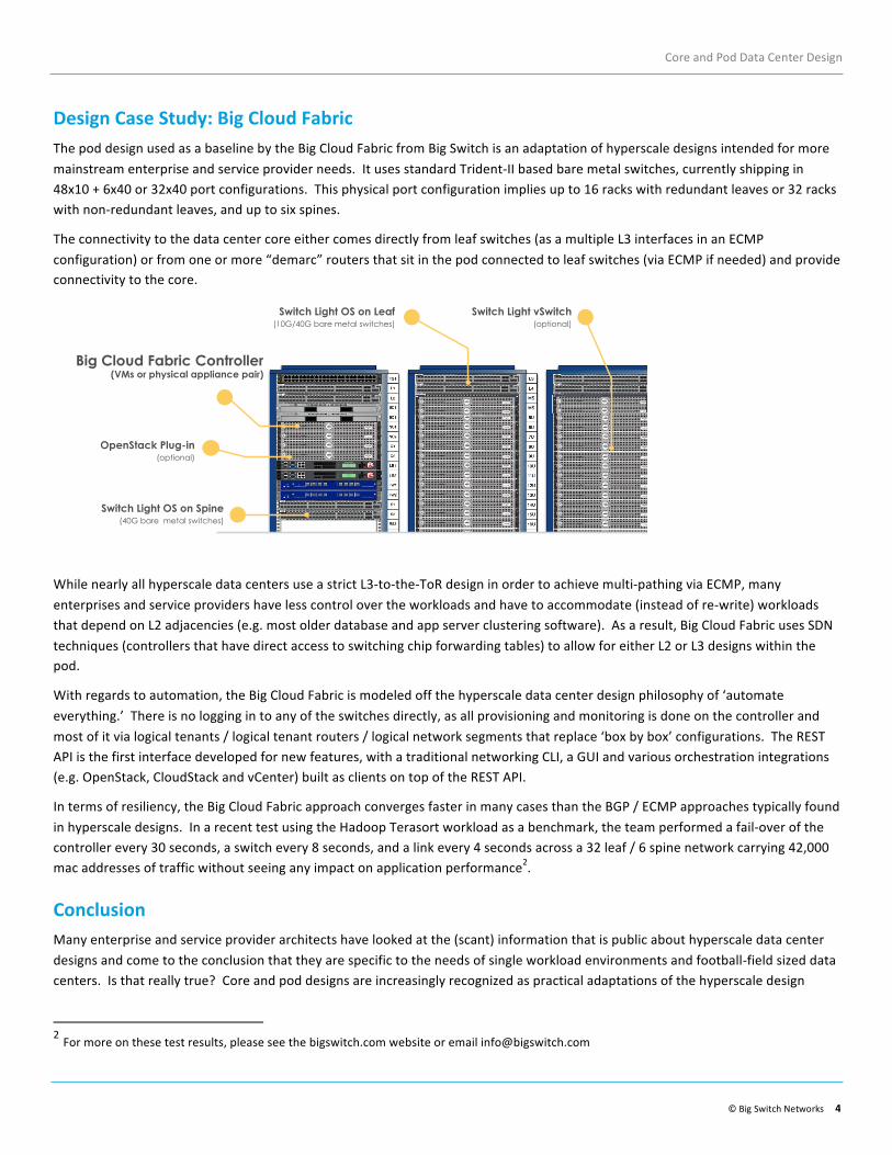
Design Case Study: Big Cloud Fabric The pod design used as a baseline by the Big Cloud Fabric from Big Switch is an adaptation of hyperscale designs intended for more mainstream enterprise and service provider needs. It uses standard Trident-‐II based bare metal switches, currently shipping in 48x10 + 6x40 or 32x40 port configurations. This physical port configuration implies up to 16 racks with redundant leaves or 32 racks with non-‐redundant leaves, and up to six spines.
The connectivity to the data center core either comes directly from leaf switches (as a multiple L3 interfaces in an ECMP configuration) or from one or more “demarc” routers that sit in the pod connected to leaf switches (via ECMP if needed) and provide connectivity to the core.
While nearly all hyperscale data centers use a strict L3-‐to-‐the-‐ToR design in order to achieve multi-‐pathing via ECMP, many enterprises and service providers have less control over the workloads and have to accommodate (instead of re-‐write) workloads that depend on L2 adjacencies (e.g. most older database and app server clustering software). As a result, Big Cloud Fabric uses SDN techniques (controllers that have direct access to switching chip forwarding tables) to allow for either L2 or L3 designs within the pod.
With regards to automation, the Big Cloud Fabric is modeled off the hyperscale data center design philosophy of ‘automate everything.’ There is no logging in to any of the switches directly, as all provisioning and monitoring is done on the controller and most of it via logical tenants / logical tenant routers / logical network segments that replace ‘box by box’ configurations. The REST API is the first interface developed for new features, with a traditional networking CLI, a GUI and various orchestration integrations (e.g. OpenStack, CloudStack and vCenter) built as clients on top of the REST API.
In terms of resiliency, the Big Cloud Fabric approach converges faster in many cases than the BGP / ECMP approaches typically found in hyperscale designs. In a recent test using the Hadoop Terasort workload as a benchmark, the team performed a fail-‐over of the controller every 30 seconds, a switch every 8 seconds, and a link every 4 seconds across a 32 leaf / 6 spine network carrying 42,000 mac addresses of traffic without seeing any impact on application performance2.
Conclusion Many enterprise and service provider architects have looked at the (scant) information that is public about hyperscale data center designs and come to the conclusion that they are specific to the needs of single workload environments and football-‐field sized data centers. Is that really true? Core and pod designs are increasingly recognized as practical adaptations of the hyperscale design
2 For more on these test results, please see the bigswitch.com website or email [email protected]
Big Cloud Fabric Controller (VMs or physical appliance pair)
Switch Light OS on Spine (40G bare metal switches)
OpenStack Plug-in (optional)
Switch Light vSwitch (optional)
Switch Light OS on Leaf (10G/40G bare metal switches)
Core and Pod Data Center Design
© Big Switch Networks 5
approach, applicable to data centers worldwide. While they are very different from the traditional core-‐aggregation-‐edge three tier data center design that most architects learn early in their careers, they are certainly applicable and (often) a better choice than these more traditional, older designs. This modular approach is easier to automate, contains failures more effectively, take advantage of price/performance advances faster than traditional designs.
At Big Switch Networks, Core and Pod designs and the hyperscale design philosophy in general have greatly informed our product design and development approach. If you are interested in learning more, check out the following resources:
• Try Big Cloud Fabric online at: labs.bigswitch.com • Big Cloud Fabric base information: www.bigswitch.com/sdn-‐products/big-‐cloud-‐fabric • Big Cloud Fabric demo video: www.bigswitch.com/videos/big-‐cloud-‐fabric-‐unboxed • Big Cloud Fabric network stack for OpenStack webinar and demo: www.bigswitch.com/webinars