Embed Size (px)
Citation preview
Corrections, Clarifications, and Comments:Hahn, Mathematical Excursions to the World’s Great Buildings ∗
Chapter 2
page 33, Figure 2.30a, should have 90◦ in place of π2
(because the radian measure of an angle is
introduced and discussed only later).
page 36, to be inserted as a paragraph before the paragraph “Another important innovation . . . .”
Water from aqueducts also drove waterwheels that provided the power for ancient industrial ap-
plications. Systems of water driven mills for grain production in Rome as well as its territories
(in Spain and southern France for instance are an important example. In the 2nd century AD, a
Roman industrial grain factory in Barbegal in southern France was powered by a complex consisting
of a series of sixteen waterwheels fed by an artificial aqueduct. The site has been referred to as
“the greatest known concentration of mechanical power in the ancient world”. The Romans also
used water wheels extensively within their mining operations. One site uncovered in Spain featured
a stacked system of such wheels that could lift water about 80 feet (24 m) from the mine sump
(a designated low space in which water collected). The first clear descriptions of watermills with
horizontal and vertical axes and gearings system was provided by Vitruvius. His account tells us
that the separate Greek inventions of the toothed gear and the water wheel combined into this
effective mechanical system for harnessing water power. The video
http://www.youtube.com/watch?v=XE2kOjNqvsw
describes some of the specifics.
page 37, end of the first paragraph. The sentences “Notice that the smooth exterior finish of
the outer oval is intact. The missing finish from the inner oval reveals the rough concrete of its
construction.” This is not quite accurate. The original construction of the Colosseum utilized
concrete for the foundation, travertine blocks (travertine is a form of lime stone) held together by
clamps for the piers and arcades, and brick faced concrete for the upper levels and most of the
vaults. There have been several reconstructions over the centuries. In particular, “the smooth
exterior finish of the outer oval” visible in Figure 2.37 is unlikely to be original. Much of “the rough
concrete” referred to is travertine. The holes that are visible are the places were the clamps once
were. The Romans did finish much of the original facade, but with marble plates.
page 40, beginning of the last paragraph. To the end of the sentence “The Romans built the
Pantheon out concrete.” add: “with intermittent courses of bricks.”
pages 46-47. The Laws of Sines and Cosines both provide important information about forces, their
resultants, and their components. The following two problems illustrate these connections.
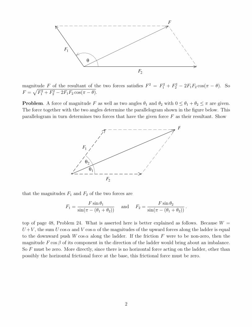
Problem. Two forces of respective magnitudes F1 and F2 act at a point. The angle between the
two forces is θ with 0 ≤ θ ≤ π. The typical situation is depicted in the figure below. Show that the
* I am grateful to Steve Wassel, Professor of Mathematics, Sweet Briar College, Virginia, for pointing out several
of the errata that follow.
θ
F
F1
F2
magnitude F of the resultant of the two forces satisfies F 2 = F 21 + F 2
2 − 2F1F2 cos(π − θ). So
F =√F 21 + F 2
2 − 2F1F2 cos(π − θ).
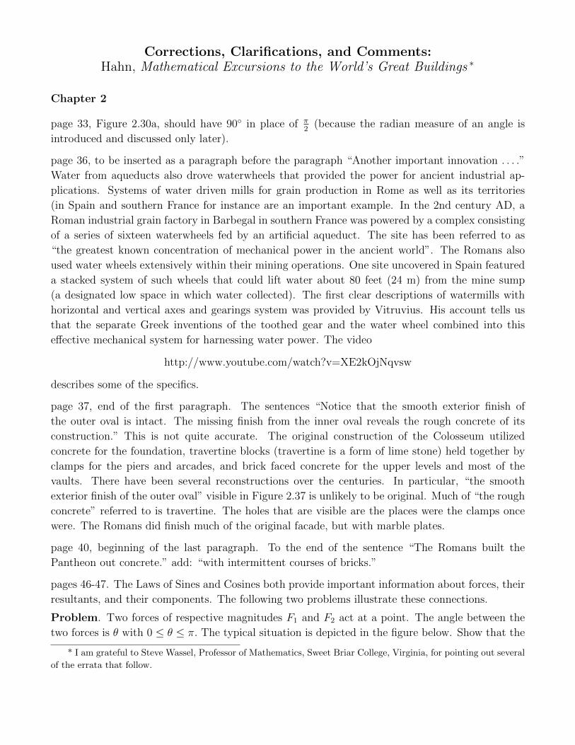
Problem. A force of magnitude F as well as two angles θ1 and θ2 with 0 ≤ θ1 + θ2 ≤ π are given.
The force together with the two angles determine the parallelogram shown in the figure below. This
parallelogram in turn determines two forces that have the given force F as their resultant. Show
θ
F
F1
F2
1
θ2
that the magnitudes F1 and F2 of the two forces are
F1 =F sin θ1
sin(π − (θ1 + θ2))and F2 =
F sin θ2sin(π − (θ1 + θ2))
.
top of page 48, Problem 24. What is asserted here is better explained as follows. Because W =
U+V , the sum U cosα and V cosα of the magnitudes of the upward forces along the ladder is equal
to the downward push W cosα along the ladder. If the friction F were to be non-zero, then the
magnitude F cos β of its component in the direction of the ladder would bring about an imbalance.
So F must be zero. More directly, since there is no horizontal force acting on the ladder, other than
possibly the horizontal frictional force at the base, this frictional force must be zero.
2
Chapter 3
page 70, consider the first sentence. “... and notice that the two cylindrical surfaces of each groin
vault give rise to two intersecting circular arcs.” The word “circular” is used here very loosely.
These arcs are not parts of circles. Rather, they are curves in three dimensions (they do not lie
in a plane). The first sentence should therefore be restated as follows: “... and notice that the
intersection of the two cylindrical surfaces that form the groin vault is given by two curves that
cross at the top of the vault.”
The mathematics of the curves that mark the intersection of two cylinders is described in a
discussion that follows below. See the insertion described for page 199.
page 88, add to the discussion about the first dome of the Hagia Sophia (after the paragraph that
ends with “... must have been larger.” : Some architectural historians who have analyzed the matter
think that the original dome was about 20 feet lower in terms of its flatness than the current dome
and about 10 feet lower in elevation. Such conclusions are plausible, but not definitive (as there are
differences of opinion about the matter). See Rabun Taylor’s article in the References. In any case,
the choice of 10 feet in the context of Problems 4 and 5 is more than enough to illustrate the point
that a flatter dome will generate a much greater outward thrust than one that rises more steeply.
page 94. Refer to Problem 19. Compare the tracery of the window of Figure 3.24 with the tracery
of the window on the left in Figure 3.31. Notice that the rosette of the cathedral of Chartres has
reflectional symmetries but that the rosette of the Duomo of Milan does not. Such windows are
unusual in the Gothic tradition, but the Duomo of Milan has several of them.
Chapter 4
page 104 and 105. Aristotle’s proof of the fact that the equality n2
m2 = 2, or equivalently n2 = 2m2,
where n and m are positive integers is not possible, is also a proof by contradiction. It uses the
fact that an integer is even, precisely if it has the form 2k for some integer k, and an integer is odd,
precisely if it has the from 2k + 1 for some integer k. So we will assume that n2
m2 = 2, where n and
m are positive integers and derive a contradiction. Start with the number nm
. After canceling 2s as
many times as this is possible, we can assume that at least one of n or m is odd. Suppose that n is
odd. So n = 2k+1. Hence n2 = (2k+1)2 = 4k2+4k+1. Since n2 = 2m2, this means that n2 is both
odd and even. But this cannot be so. Therefore, n must be even and hence m must be odd. Let’s
put n = 2l and m = 2k+ 1. Then 4l2 = n2 = 2m2 = 2(2k+ 1)2. So 2l2 = (2k+ 1)2 = 4k2 + 4k+ 1.
But this means that the number 2l2 is both odd and even. This is the contradiction that proofs the
assertion that the equality n2
m2 = 2, where n and m are positive integers is impossible.
page 127, Problem 1. The assertion “Tilt it so that the tube is parallel to the wall, and you will
get a parabola,” is wrong and should be replaced by “Tilt more, but carefully, until the part of the
beam farthest from the wall no longer hits the wall. At the moment this occurs you will have a
parabola.” (What curve appears when the tube is parallel to the wall?)
pages 129, 130, and 131. Missing hyphens. In Problem 18, it should be ”xy-coordinate”; in Problem
3
22, “xy-plane”; in Problems 26 and 27, “xy-plane”; in the paragraph “The discussion about . . . ”
on page 131 it should be “xy-plane” and“ xyz-space” and in Problem 36, “xy-coordinate plane”.
page 130. Add the following two problems after Problem 30.
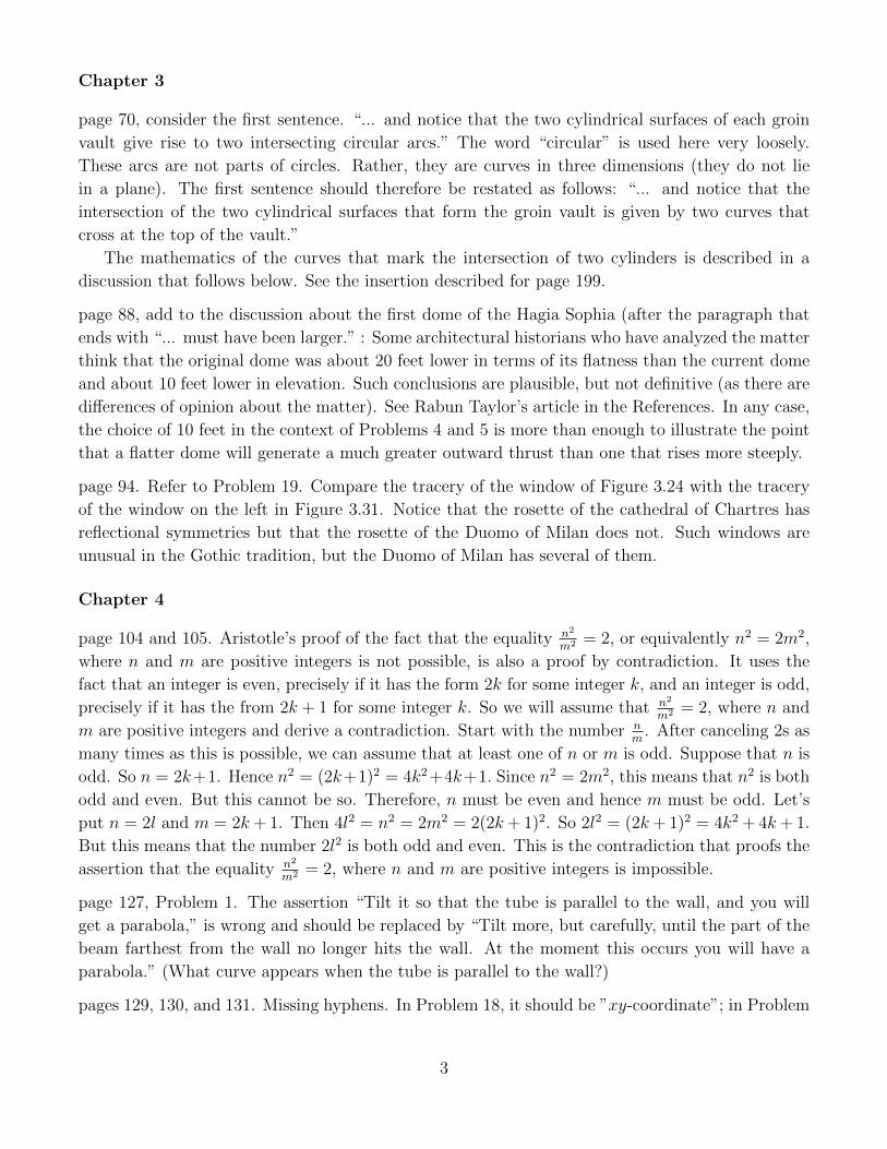
Problem. The point F and the line L in the diagram below determine a parabola. The given
segment specifies a distance d. Describe a straightedge and compass construction of that point P
F
directrix
d
L
on the parabola that has PF = PL = d. [Hint: Start by constructing a line parallel to L at a
distance d from L.]
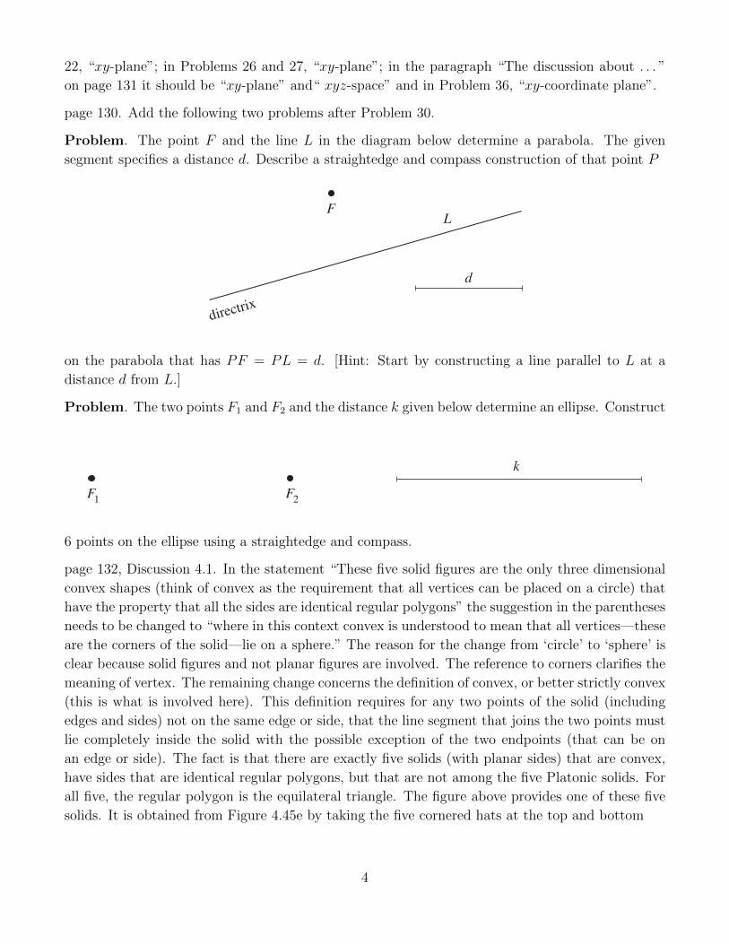
Problem. The two points F1 and F2 and the distance k given below determine an ellipse. Construct
F
k
F1 2
6 points on the ellipse using a straightedge and compass.
page 132, Discussion 4.1. In the statement “These five solid figures are the only three dimensional
convex shapes (think of convex as the requirement that all vertices can be placed on a circle) that
have the property that all the sides are identical regular polygons” the suggestion in the parentheses
needs to be changed to “where in this context convex is understood to mean that all vertices—these
are the corners of the solid—lie on a sphere.” The reason for the change from ‘circle’ to ‘sphere’ is
clear because solid figures and not planar figures are involved. The reference to corners clarifies the
meaning of vertex. The remaining change concerns the definition of convex, or better strictly convex
(this is what is involved here). This definition requires for any two points of the solid (including
edges and sides) not on the same edge or side, that the line segment that joins the two points must
lie completely inside the solid with the possible exception of the two endpoints (that can be on
an edge or side). The fact is that there are exactly five solids (with planar sides) that are convex,
have sides that are identical regular polygons, but that are not among the five Platonic solids. For
all five, the regular polygon is the equilateral triangle. The figure above provides one of these five
solids. It is obtained from Figure 4.45e by taking the five cornered hats at the top and bottom
4
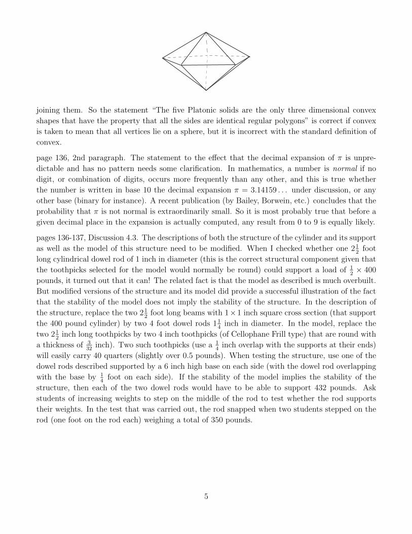
joining them. So the statement “The five Platonic solids are the only three dimensional convex
shapes that have the property that all the sides are identical regular polygons” is correct if convex
is taken to mean that all vertices lie on a sphere, but it is incorrect with the standard definition of
convex.
page 136, 2nd paragraph. The statement to the effect that the decimal expansion of π is unpre-
dictable and has no pattern needs some clarification. In mathematics, a number is normal if no
digit, or combination of digits, occurs more frequently than any other, and this is true whether
the number is written in base 10 the decimal expansion π = 3.14159 . . . under discussion, or any
other base (binary for instance). A recent publication (by Bailey, Borwein, etc.) concludes that the
probability that π is not normal is extraordinarily small. So it is most probably true that before a
given decimal place in the expansion is actually computed, any result from 0 to 9 is equally likely.
pages 136-137, Discussion 4.3. The descriptions of both the structure of the cylinder and its support
as well as the model of this structure need to be modified. When I checked whether one 212
foot
long cylindrical dowel rod of 1 inch in diameter (this is the correct structural component given that
the toothpicks selected for the model would normally be round) could support a load of 12× 400
pounds, it turned out that it can! The related fact is that the model as described is much overbuilt.
But modified versions of the structure and its model did provide a successful illustration of the fact
that the stability of the model does not imply the stability of the structure. In the description of
the structure, replace the two 212
foot long beams with 1×1 inch square cross section (that support
the 400 pound cylinder) by two 4 foot dowel rods 114
inch in diameter. In the model, replace the
two 212
inch long toothpicks by two 4 inch toothpicks (of Cellophane Frill type) that are round with
a thickness of 332
inch). Two such toothpicks (use a 14
inch overlap with the supports at their ends)
will easily carry 40 quarters (slightly over 0.5 pounds). When testing the structure, use one of the
dowel rods described supported by a 6 inch high base on each side (with the dowel rod overlapping
with the base by 14
foot on each side). If the stability of the model implies the stability of the
structure, then each of the two dowel rods would have to be able to support 432 pounds. Ask
students of increasing weights to step on the middle of the rod to test whether the rod supports
their weights. In the test that was carried out, the rod snapped when two students stepped on the
rod (one foot on the rod each) weighing a total of 350 pounds.
5
Chapter 5
page 143, the three parenthetical remarks in the first paragraph should be changes as follows: in the
first, “shown in gray” should be replaced by “shown in black”, in the second, “also in gray” should
be replaced by “also in black”, and in the third, “in black” should be replaced by “in white”.
page 149, bottom of the page. The old Venetian foot was in fact slightly larger than the foot we use
today. While the piede varied even within the same region, the values for Venice and the Veneto
region are in the 34.7 to 35.4 cm range (about 13.66 to 13.94 inches). See Steve Wassel’s chapter in
the book Andrea Palladio: Villa Cornaro in Piombino Dese, edited by Branko Mitrovic and Steve
Wassel and published by Acanthus Press.
pages 168–171. In a second edition, the section “Bernini’s Baroque Basilica” should be renamed and
expanded into “Baroque Rome: Bernini and Borromini.” The Italian architect Francesco Borromini
(1599-1667) was the second extraordinary figure of Roman Baroque. While Bernini’s work remained
closer to the aims and ideals of the classical Renaissance, Borromini represented a more imaginative
and geometrically daring approach to baroque architecture. After several years training in both
architecture and sculpture in Milan, he came to Rome to work as draftsman and stonemason for
Carlo Maderno, assisting the aging capomaestro with the work on St. Peter’s. Later, Borromini
closely collaborated with Bernini in the realization of the bronze baldacchino. Bernini was in
command, but paid Borromini a substantial sum from 1631 to 1633 for his work. The Roman
churches of Sant’ Ivo alla Sapienza (1640-1650) and San Carlo alle Quattro Fontane (1638–1641)
as well as Oratory of Saint Philip Neri (1637–1643) with its library are the most distinctive of
Borromini’s creations. Their exteriors feature sensuously curving facades and their interiors are
characterized by dynamic plans and beautifully mathematical geometries.
page 173. Insert the remark: “It is the purpose of this section and the next to demonstrate that all
the essential strategies and properties of rendering an image in perspective are not simply a matter
of drawing by using certain rules and conventions that work. Rather, they are all consequences of
the mathematical properties of three dimensional space.” before ’Before’ in the third paragraph.
page 196, second paragraph. Delete the sentence: “Accordingly, one speaks of one-, two-, or three-
point perspective.” It is incorrect (with regard to the standard definitions of these terms). Change
the sentence “The depiction of Alberti’s floor in Figure 5.49b with its focus on vertical and diagonal
lines is an example of a drawing in two-point perspective.” to “The head-on depiction of Alberti’s
tile floor in Figure 5.49b with its focus on a primary central vanishing point is an example of a
drawing in one-point perspective.”
page 196, add before Problem 11: The solutions of Problems 11 to 30 that follow require facts
developed in the section “Brunelleschi and Perspective.”
page 198, Problem 16. For clarity, replace the last sentence by: Repeat this with P2 – P1 to obtain
two more sets of parametric equations for L.
page 199. Add the following two problems after Problem 21.
6
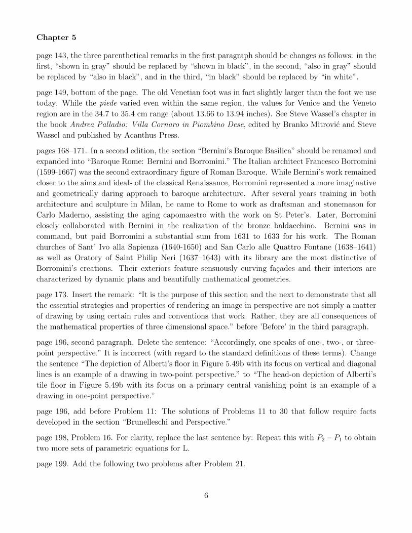
Problem. Consider a xyz-coordinate space and the two cylinders determined by the two circles
x2 + z2 = 4 and y2 + z2 = 4. The axes of the two cylinders are the x and y axes respectively. The
upper halves of the two cylinders are depicted in the figure below. Show that the intersection of
these two upper halves consists of two curves that lie in the respective planes y = x and y = −x
y
x
2
z
y + z = 42
2x + z = 4
2
and that each of these curves is the upper half of an ellipse with semiminor axis 2 and semimajor
axis 2√
2. They are given by the two sets of parametric equations x = t, y = t, z =√
4− t2 and
x = t, y = −t, z =√
4− t2 with −2 ≤ t ≤ 2.
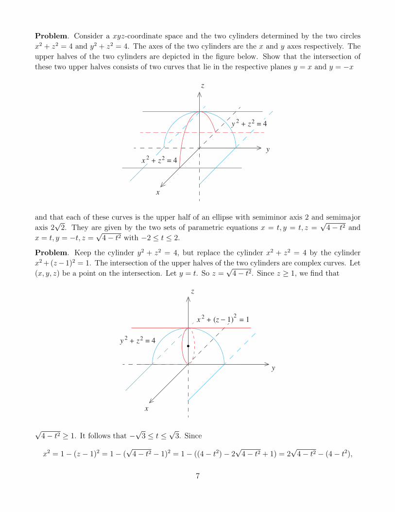
Problem. Keep the cylinder y2 + z2 = 4, but replace the cylinder x2 + z2 = 4 by the cylinder
x2 + (z− 1)2 = 1. The intersection of the upper halves of the two cylinders are complex curves. Let
(x, y, z) be a point on the intersection. Let y = t. So z =√
4− t2. Since z ≥ 1, we find that
y
x
2
z
x + (z − 1) = 12
2y + z = 4
2
√4− t2 ≥ 1. It follows that −
√3 ≤ t ≤
√3. Since
x2 = 1− (z − 1)2 = 1− (√
4− t2 − 1)2 = 1− ((4− t2)− 2√
4− t2 + 1) = 2√
4− t2 − (4− t2),
7
x = ±√
2√
4− t2 − (4− t2). So
x =
√2√
4− t2 − (4− t2), y = t, z =√
4− t2
and x = −√
2√
4− t2 − (4− t2), y = t, z =√
4− t2 with −√
3 ≤ t ≤√
3 in each case, are the two
sets of parametric equations that determine the curves. Why can’t even a small part of either curve
lie entirely in one plane?
The best way to visualize what is going on is to start on the y-axis with y = t and t =√
3. Then
look at z =√
4− t2 and notice that as t moves to zero, the point (y, z) climbs up along the circle
y2 +z2 = 4. The most subtle aspect is the behavior of the x-coordinate x = ±√
2√
4− t2 − (4− t2)
as this climb occurs. Consider x =√
2√
4− t2 − (4− t2) for instance. In this case, x moves from
very subtly from x = 1 to x = 0. Refer to Figure 3.19. The two dashed curves define the intersection
of the two perpendicular barrel vaults that form the groin vault that is depicted. The larger of the
two is a part of the vaulting of the nave, the smaller reaches from the clerestory window on the one
side to that on the other. Geometrically, these two curves are the intersection of two horizontal and
perpendicular cylinders. They are described mathematically by the problem above.
page 202, after Problem 30: Change “We turn next to study examples . . . involving perspective” as
follows: “Problems 31 to 37 study examples of quadratic equations and conic sections and Problems
38 and 39 analyze the perspective images of circles on Alberti’s tile floor. All these problems rely
on the section “From Circle to Ellipse.”
page 204, Problem 38 iii. Change the problem to: For any of the circles under discussion, d = 2
and ycen > h = 22, so that d + ycen > 1 and −4e2((d + ycen)2 − 1) < 0. This confirms that the
perspective image of the circle is an ellipse. But what if d = 1, h = 0, and ycen = 0? In this case,
the artist looks out on a semicircle of radius 1. What kind of curve would he draw on his canvas (if
he were to follow Alberti’s rule)?
Chapter 6
page 205. The larger scale ... requires. (add an s).
page 217. Insert as last paragraph before the section Hanging Chains and Rising Domes.
According to recent information released by the current architect of the Capitol, the 150 year old
dome is in fact facing structural problems that need attention. “From a distance, the Dome looks
magnificent, thanks to the hard-work of our employees. On closer look under the paint, age and
weather have taken its toll” and repairs need to be made to preserve the Dome. Up close surveys
have revealed more than 1,000 cracks that have to be attended to now. The restorations called for
will be the first in about 50 years. They began late in 2013 and are expected to take about two
years at cost of about $60 million. Extensive scaffolding will be placed on the exterior and interior
of the dome, cast iron will be repaired as needed, windows will be repaired and replaced, new coats
of paint will be applied. The scaffold system will surround the entire Dome from the base of the
8
Statue of Freedom down to the top of the skirt at its base. Scaffold towers and scaffold bridging
will be constructed on the west side of the U.S. Capitol Building so that materials can be moved
to the construction sites.
pages 220 to 226. The discussion from: “The story of the validation . . . ” (on page 220) to “. . .
and the related static behavior between the components into account.” (on page 226) should be
placed into a new section with the title “From the Strings of Varignon to the Theorem of Heyman”.
Both this new section and the section “Analyzing Structures: Statics and Materials” that follows it
should be marked with a * pointing to separate footnotes asserting that both of these sections are
technical and may be skipped. The fact is that only the last section “The Calculus of Moments and
Centers of Mass” of Chapter 7 is impacted by them (primarily by “Analyzing Structures: Statics
and Materials”).
pages 232 to 233. This book is not intended to be a forum for a discussion of the merits of Coulomb’s
theory of arches, or more generally, of Coulomb’s memoir Essay on Problems of Statics of 1773.
However, given the considerable attention that these Mathematical Excursions gives to Coulomb’s
theory, it is instructive to summarize what is said about both in Stephen Timoshenko, History of
Strength of Materials, Dover Publications, Inc., New York, 1983. It is pointed out that at the end
of the eighteenth century, a considerable number of tests were performed on arches that upheld the
assumptions that Coulomb made in the development of his analysis. This analysis of arches does
not (as we have seen) give definitive rules for designing them, but only determines limits for the
thrusts that ensure stability. For this reason, Coulomb’s work was not appreciated by the engineers
of his time. But in the nineteenth century, after graphic methods were developed for calculating
the limits (d) and (e) (this is a reference to the inequality G0 ≤ H ≤ G1 discussed in the section
“Analyzing Structures: Statics and Materials”) arch builders used his ideas extensively. Coulomb’s
landmark memoir also discusses other important problems in the mechanics of materials, including
the testing of the strength of materials, the theory of bending of beams (Coulomb uses the equations
of statics correctly to study the internal forces in a beam and has clear ideas about the distribution
of these forces over its cross section), the compression of a prism by an axial force, and the stability
of retaining walls) and offers correct solutions of several of them. But it took engineers more than
forty years to understand them satisfactorily and to use them in practical applications.
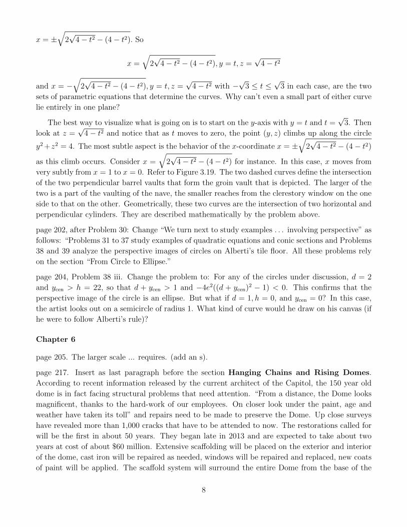
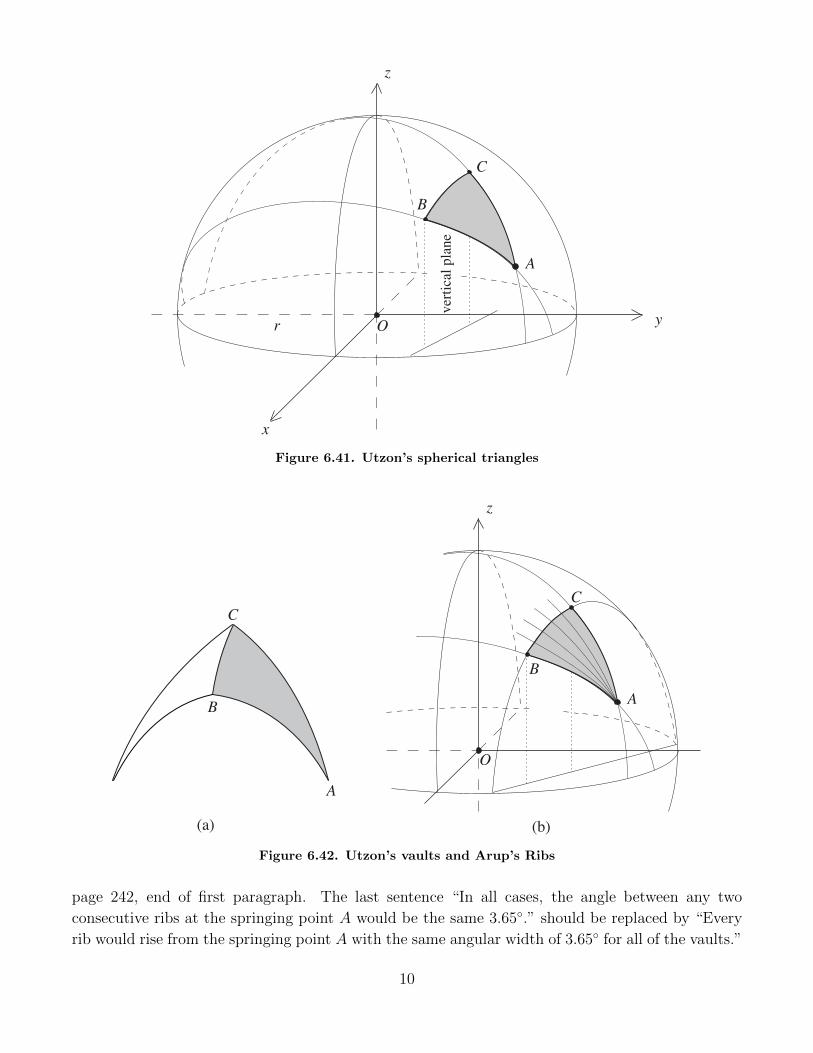
page 241. In the definition of Utzon’s spherical triangles given in this paragraph, it is too restrictive
to assume that the point A lies on the y-axis. The modification that needs to be made follows.
Replace the existing Figures 6.41 and 6.42 by the versions below. Change the discussion in the
paragraph “Let’s analyze the curving triangles . . . ” as follows: Refer to Figure 6.41. Let A,B, and
C be three distinct points on the upper half of the sphere. Consider the plane determined by the
points A,B and the center O of the sphere. This plane intersects the sphere in a circle on which
both A and B lie. In the same way, the points A,C and O determine a plane and hence a circle on
the sphere on which the points A and C lie. Any circle obtained as the intersection of the sphere
with a plane through the origin O is called a great circle. The arcs BC and AC in the figure are
those that are determined by the two great circles just described. Now project the points B and C
into the xy-plane . . . Leave the rest of the paragraph as is.
9
B
ver
tica
l pla
ne
y
x
z
O
A
C
r
Figure 6.41. Utzon’s spherical triangles
B
z
O
A
C
(a) (b)
A
C
B
Figure 6.42. Utzon’s vaults and Arup’s Ribs
page 242, end of first paragraph. The last sentence “In all cases, the angle between any two
consecutive ribs at the springing point A would be the same 3.65◦.” should be replaced by “Every
rib would rise from the springing point A with the same angular width of 3.65◦ for all of the vaults.”
10
page 243, second line from the top. The 220 feet (more accurately, 221 feet) refers to the height of
the top of shell A2 above sea level. The height of the top of the shell as measured from its base at
the Podium is 179 feet.
page 258. Problem 8. This problem was taken from a secondary source. After reflecting about it
later, it was difficult for me to believe that Wren would have thought an arch to be stable as long
as the rotational effect of the pier to the left would be greater than the rotational effect of the arch
to the right. So I went back to the original source and found that Wren does seem to be saying just
this. We’ll cite the relevant passage from page 245 of the Parentalia (it references a figure—Wren’s
version of Figure 6.51—on page 243) because it includes interesting comments by Wren about both
the Pantheon and St. Peter’s in Rome.
“Let a Stone be cut in this Form [he refers to his version of Figure 6.51], FB a Parallelogram,
CD a Semicircle added, AB a Perpendicular, M the Center of Gravity of FB, and N of ACD, now
if N be equiponderant [this means: to be equal or balanced in weight, power, force] to M on each
Side the Perpendicular AB, it is certain the whole Stone will stand immoveable upon the Basis at
B, although it be but half an Arch; add the like Stone on the opposite Side, till the Horns meet in
an entire Arch, so the Whole will stand as well as the Halves. If any thing be added without M ,
that alters nothing, only ’tis an useless Expence; but if any thing be added above N , that alters
the Center of Gravity, which therefore must be provided for, by adding more Weight to M ; and
the same may be shewn in all kinds of Vaulting. So it appears that the Design, where there are
Arcades, must be regulated by the Art of Staticks, or Invention of the Centers of Gravity, and the
duly poising [to bring into balance, equilibrium] all Parts to equiponderate; without which, a fine
Design will fail and prove abortive. Hence I conclude, that all Designs must, in the first place, be
brought to this Test, or rejected. I have examined some celebrated Works, as the Pantheon, and
judge there is more Butment than necessary, though it is flat and low; but I suppose the Architect
provided it should stand against Earthquakes, as indeed it hath, and will. The great Fabrick of St.
Peter’s if it had been followed as Bramante had designed it, would have been as durable; but the
Butment of the Cupola was not placed with Judgment: however, since it was hooped with Iron, it
is safe at present, and, without an Earthquake, for Ages to come. Iron, at all Adventures, is a good
Caution; but the Architect should so poise his Work, as if it were not necessary.”
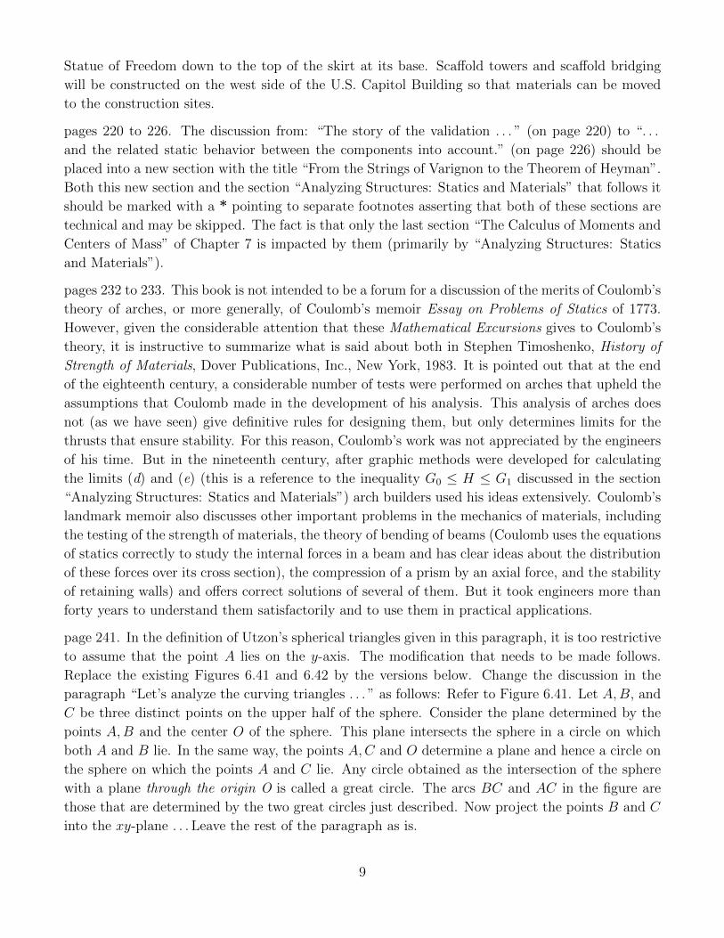
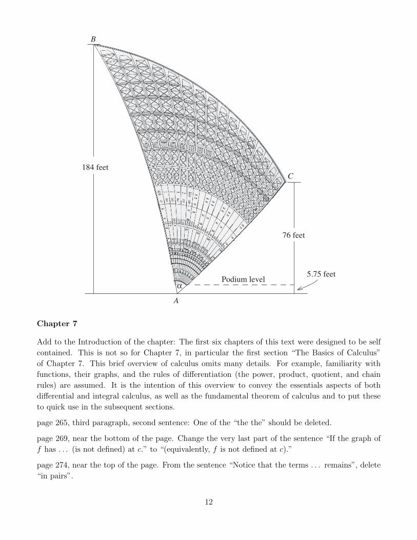
pages 261 and 262. In Discussion 6.2, in particular in Figures 6.56, 6.57a, and 6.57b, and Problem 16,
the heights of 220 and 86 feet are incorrect and need to be changed to 184 and 76 feet as defined
in the figure on the next page. I wish to thank both Kerry Stubley, Administration & Systems
Coordinator, as well as Chris Linning, Manager of Building Information of the Sydney Opera
House for supplying these corrections and much additional information.
page 262, Figure 6.57, replace ϕB and ϕC by φB and φC , respectively.
Problem 17, change “spherical” to “geodesic” in the sentence “... is the triangle ABC in Figure
6.41 a spherical triangle?”
page 264, line 11 from the bottom: one too many ts in Bonnett
11
184 feet
76 feet
A
B
C
αPodium level
5.75 feet
Chapter 7
Add to the Introduction of the chapter: The first six chapters of this text were designed to be self
contained. This is not so for Chapter 7, in particular the first section “The Basics of Calculus”
of Chapter 7. This brief overview of calculus omits many details. For example, familiarity with
functions, their graphs, and the rules of differentiation (the power, product, quotient, and chain
rules) are assumed. It is the intention of this overview to convey the essentials aspects of both
differential and integral calculus, as well as the fundamental theorem of calculus and to put these
to quick use in the subsequent sections.
page 265, third paragraph, second sentence: One of the “the the” should be deleted.
page 269, near the bottom of the page. Change the very last part of the sentence “If the graph of
f has . . . (is not defined) at c.” to “(equivalently, f is not defined at c).”
page 274, near the top of the page. From the sentence “Notice that the terms . . . remains”, delete
“in pairs”.
12
page 281, in the inequality in the middle of the page,
W ≤ 190,000 should be replaced by W ≤ 191,000.
page 284, second line from the bottom. The horizontal bar of the square root symbol should not
cut the symbol C0.
page 286. Insert as a new paragraph after the paragraph ending with “ . . . fits neatly into a 630
by 630 foot square.”
Note that an arch that is built in the shape of a catenary (or possibly a related curve) will
never, in terms of its structural properties, satisfy the assumptions made in the derivation of this
geometry. The assumption that “the gravitational forces on the arch are perfectly balanced by its
reaction to the compressions that these forces generate” made at the beginning of the section “The
Shape of an Ideal Arch” is the important case in point. The Gateway Arch in St. Louis does not
satisfy any such an assumption, not because it is a compressed catenary (and hence not a catenary),
but because it gains its strength from its visible outer structure in stainless steel, a parallel inner
stainless steel core, and the reinforced concrete that fills the space between them (up to a height
of 300 feet). The point is that the catenary is an attractive curve and that an arch can be built in
this ideal shape without having to conform to the structural assumptions that determine the curve.
page 294, Problem 12. There is a typo in the statement of this problem. What needs to be
derived is the estimate of 23,300 ft3 for the volume and not the estimate of 23,300 pounds for the
weight of the original dome. The estimate of 23,300 ft3 for the volume implies that the estimate of
23,300× 110 ≈ 2,560,000 pounds for the weight of the original dome (as called for in Problem 5 of
Chapter 3).
page 294, Problem 13. The data D = 16 and E = 48 are needed as well.
page 294, Problem 14. Delete V1 = as this suggests that the integral that follows is the same as
that of the discussion on page 280. (It is not.)
page 295, in Problem 15, replace (D, a) by (D, 0).
page 296. Problem 20. This question is clarified and answered by the paragraph formulated above
for inclusion on page 286.
page 299, 300. Problems 31 to 36 not only illustrate the importance of the location of the horizontal
force H in Coulomb’s analysis of the stability of arches (see Figures 7.25a and 7.25b), but that
calculus does—contrary to Coulomb’s own assessment—inform this analysis. The solutions of these
problems also tell us that the functions Wαx0y0
and Wαx1y1
that are developed in the section “Calculating
Coulomb’s Arch” are, respectively, equal to
Wαx0y0
=[12w(R2 − r2) α sinα
1− cosα− 1
3wr(R3 − r3)
][ 1− cosαRr− cosα
]and
Wαx1y1
=[12w(R2 − r2) α sinα
1− cosα− 1
3wR
(R3 − r3)][ 1− cosα
rR− cosα
]13
and that both factors are informed by the strategies that calculus provides.
14