Embed Size (px)
Citation preview
8/8/2019 Cours d'éléctronique pour les débutants 8
http://slidepdf.com/reader/full/cours-delectronique-pour-les-debutants-8 1/39
Analog and Digital MultimetersAnalog and Digital Multimeters
Topics Covered in Chapter 8
8-1: Moving-Coil Meter
8-2: Meter Shunts8-3: Voltmeters
8-4: Loading Effect of a Voltmeter
8-5: Ohmmeters
Chapter Chapter 88
© 2007 The McGraw-Hill Companies, Inc. All rights reserved.
8/8/2019 Cours d'éléctronique pour les débutants 8
http://slidepdf.com/reader/full/cours-delectronique-pour-les-debutants-8 2/39
Topics Covered in Chapter 8Topics Covered in Chapter 8
8-6: Multimeters
8-7: Digital Multimeters (DMMs)
8-8: Meter Applications
8-9: Checking Continuity with the Ohmmeter
8/8/2019 Cours d'éléctronique pour les débutants 8
http://slidepdf.com/reader/full/cours-delectronique-pour-les-debutants-8 3/39
8/8/2019 Cours d'éléctronique pour les débutants 8
http://slidepdf.com/reader/full/cours-delectronique-pour-les-debutants-8 4/39
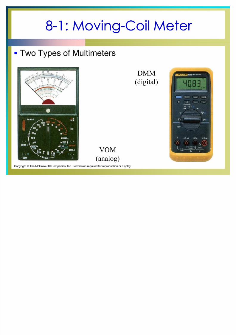
88--1: Moving1: Moving--Coil Meter Coil Meter
Types of Meters
Analog meter :
Uses a moving pointer and a printed scale to indicate
values of voltage, current, or resistance.
Volt-Ohm-Milliammeter (VOM):
Allows all three kinds of measurements on a single
scale or readout.
Digital multimeter :
Uses a numerical readout to indicate the measured
value of voltage, current or resistance.
8/8/2019 Cours d'éléctronique pour les débutants 8
http://slidepdf.com/reader/full/cours-delectronique-pour-les-debutants-8 5/39
88--1: Moving1: Moving--Coil Meter Coil Meter
Direct Current Meters
Direct current in a moving-coil meter deflects the pointer
in proportion to the amount of current.
A current meter must be connected in series with the
part of the circuit where the current is to be measured.
A dc current meter must be connected with the correct
polarity.
8/8/2019 Cours d'éléctronique pour les débutants 8
http://slidepdf.com/reader/full/cours-delectronique-pour-les-debutants-8 6/39
88--1: Moving1: Moving--Coil Meter Coil Meter
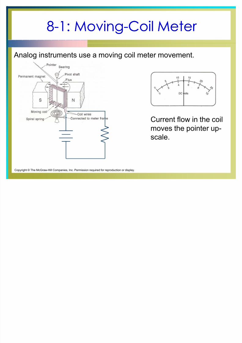
Analog instruments use a moving coil meter movement.
Current flow in the coil
moves the pointer up-scale.
Copyright © The McGraw-Hill Companies, Inc. Permission required for reproduction or display.
8/8/2019 Cours d'éléctronique pour les débutants 8
http://slidepdf.com/reader/full/cours-delectronique-pour-les-debutants-8 7/39
88--2: Meter Shunts2: Meter Shunts
Meter Shunts
Meter shunts are low-value precision resistors that are
connected in parallel with the meter movement.
Meter shunts bypass a portion of the current around the
meter movement. This process extends the range of
currents that can be read with the same meter
movement.
8/8/2019 Cours d'éléctronique pour les débutants 8
http://slidepdf.com/reader/full/cours-delectronique-pour-les-debutants-8 8/39
88--2: Meter Shunts2: Meter Shunts
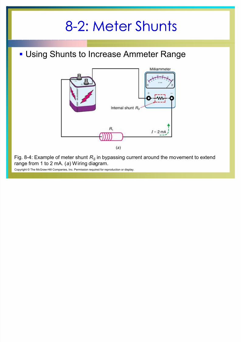
Using Shunts to Increase Ammeter Range
Fig. 8-4: Example of meter shunt R S in bypassing current around the movement to extend
range from 1 to 2 mA. (a) Wiring diagram.Copyright © The McGraw-Hill Companies, Inc. Permission required for reproduction or display.
8/8/2019 Cours d'éléctronique pour les débutants 8
http://slidepdf.com/reader/full/cours-delectronique-pour-les-debutants-8 9/39
88--2: Meter Shunts2: Meter Shunts
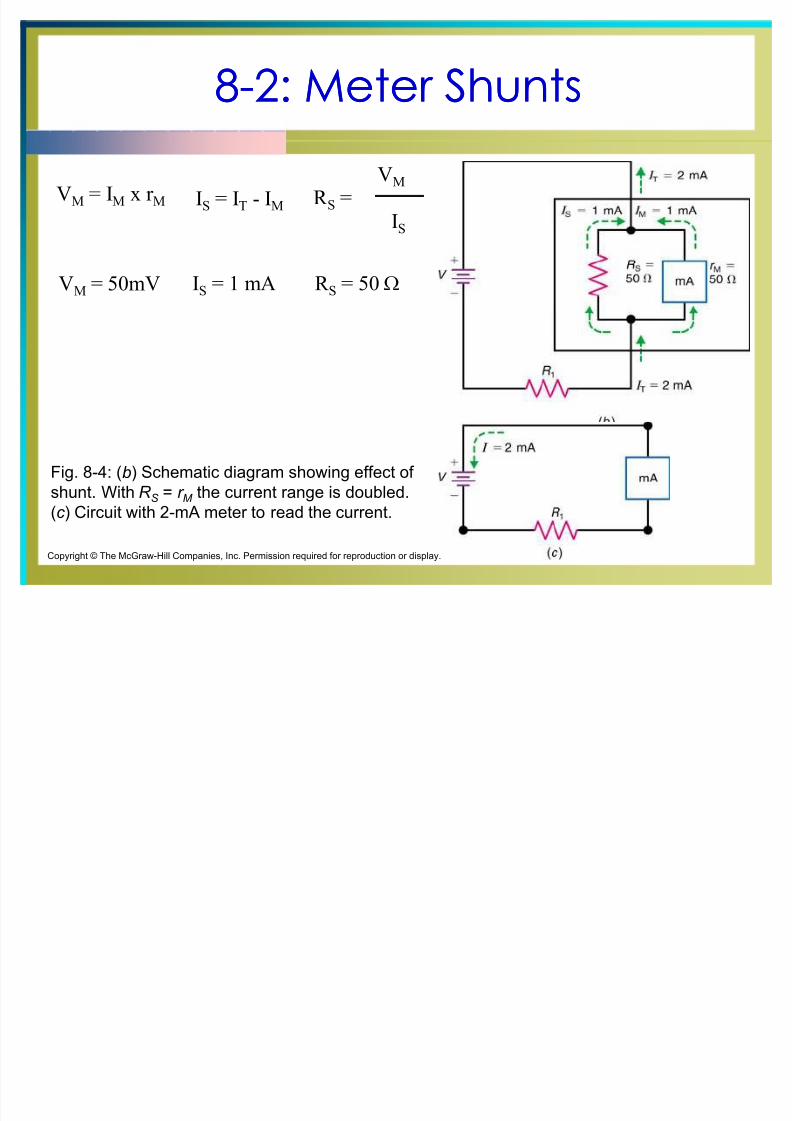
Fig. 8-4: (b) Schematic diagram showing effect of
shunt. With R S = r M the current range is doubled.
(c ) Circuit with 2-mA meter to read the current.
VM = IM x r M IS = IT - IM R S =VM
IS
VM = 50mV IS = 1 mA R S = 50 ;
Copyright © The McGraw-Hill Companies, Inc. Permission required for reproduction or display.
8/8/2019 Cours d'éléctronique pour les débutants 8
http://slidepdf.com/reader/full/cours-delectronique-pour-les-debutants-8 10/39
88--2: Meter Shunts2: Meter Shunts
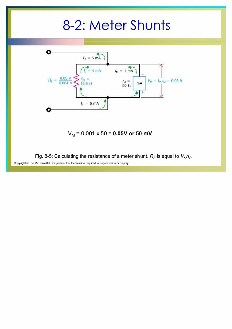
Fig. 8-5: Calculating the resistance of a meter shunt. R S
is equal to V M /I
S .
Copyright © The McGraw-Hill Companies, Inc. Permission required for reproduction or display.
VM = 0.001 x 50 = 0.05V or 50 mV

8/8/2019 Cours d'éléctronique pour les débutants 8
http://slidepdf.com/reader/full/cours-delectronique-pour-les-debutants-8 11/39
88--2: Meter Shunts2: Meter Shunts
Fig. 8-5: Calculating the resistance of a meter shunt. R S
is equal to V M /I
S .
Copyright © The McGraw-Hill Companies, Inc. Permission required for reproduction or display.
IS = 0.005 í 0.001 = 0.004 A or 4 mA
8/8/2019 Cours d'éléctronique pour les débutants 8
http://slidepdf.com/reader/full/cours-delectronique-pour-les-debutants-8 12/39
88--2: Meter Shunts2: Meter Shunts
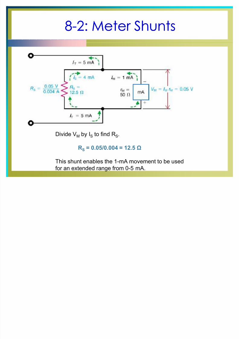
Divide VM by IS to find RS.
RS = 0.05/0.004 = 12.5
This shunt enables the 1-mA movement to be used
for an extended range from 0-5 mA.
8/8/2019 Cours d'éléctronique pour les débutants 8
http://slidepdf.com/reader/full/cours-delectronique-pour-les-debutants-8 13/39
88--3: Voltmeters3: Voltmeters
A voltmeter is connected across two points to measure
their difference in potential.
A voltmeter uses a high-resistance multiplier in series
with the meter movement. A dc voltmeter must be connected with the correct
polarity.
8/8/2019 Cours d'éléctronique pour les débutants 8
http://slidepdf.com/reader/full/cours-delectronique-pour-les-debutants-8 14/39
88--3: Voltmeters3: Voltmeters
A multiplier resistor is a large resistance in
series with a moving-coil meter movement
which allows the meter to measure voltagesin a circuit.
8/8/2019 Cours d'éléctronique pour les débutants 8
http://slidepdf.com/reader/full/cours-delectronique-pour-les-debutants-8 15/39
88--3: Voltmeters3: Voltmeters
DCV
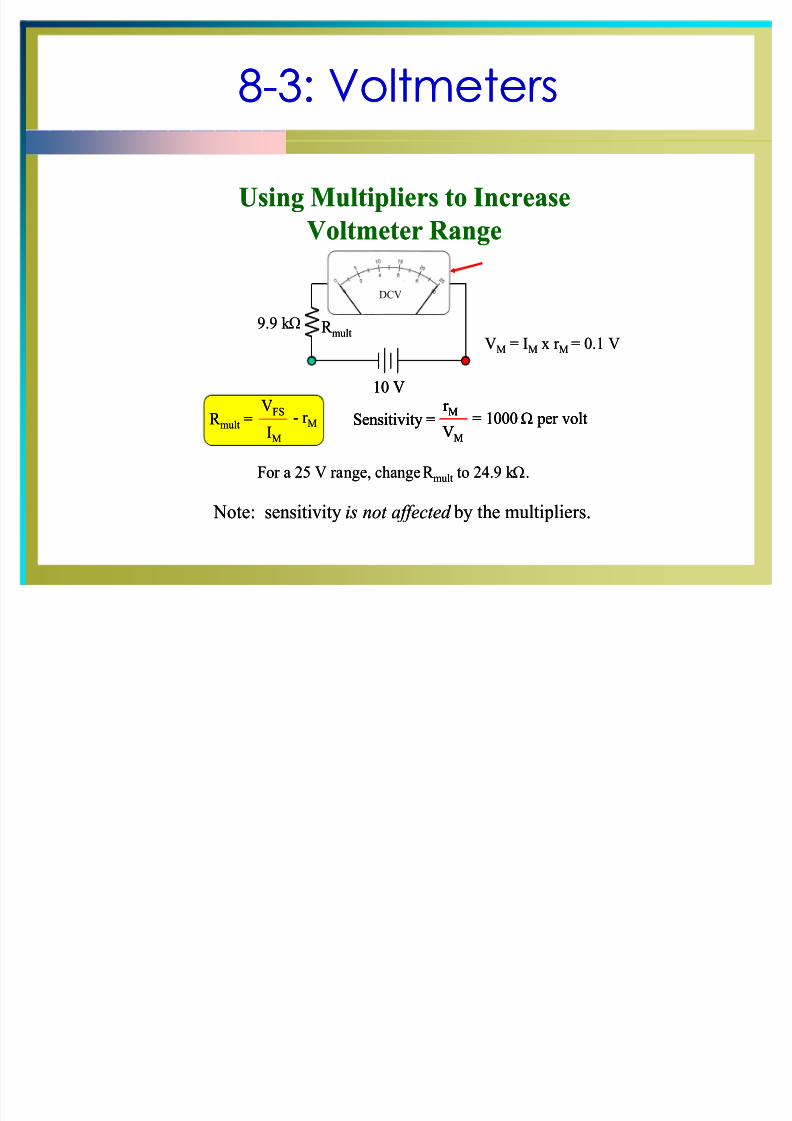
Using Multipliers to Increase
Voltmeter Range
VM = IM x r M = 0.1 V
9.9 k ;
Sensitivity =r M
VM
= 1000; per voltR mult =V
FS
IM
- r M
R mult
10 V
For a 25 V range, change R mult to 24.9 k ;.
Note: sensitivity is not affected by the multi plier s.
DCV
Using Multipliers to Increase
Voltmeter Range
VM = IM x r M = 0.1 V
9.9 k ;
Sensitivity =r M
VM
= 1000; per voltSensitivity =r M
VM
= 1000; per voltR mult =V
FS
IM
- r MR mult =V
FS
IM
- r M
R mult
10 V10 V
For a 25 V range, change R mult to 24.9 k ;.
Note: sensitivity is not affected by the multi plier s.
8/8/2019 Cours d'éléctronique pour les débutants 8
http://slidepdf.com/reader/full/cours-delectronique-pour-les-debutants-8 16/39
88--3: Voltmeters3: Voltmeters
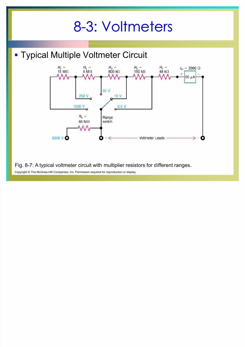
Typical Multiple Voltmeter Circuit
Fig. 8-7: A typical voltmeter circuit with multiplier resistors for different ranges.
Copyright © The McGraw-Hill Companies, Inc. Permission required for reproduction or display.
8/8/2019 Cours d'éléctronique pour les débutants 8
http://slidepdf.com/reader/full/cours-delectronique-pour-les-debutants-8 17/39
88--3: Voltmeters3: Voltmeters
Voltmeter Resistance
The high resistance of a voltmeter with a
multiplier is essentially the value of the
multiplier resistance.
Since the multiplier is changed for each
range, the voltmeter resistance changes.
8/8/2019 Cours d'éléctronique pour les débutants 8
http://slidepdf.com/reader/full/cours-delectronique-pour-les-debutants-8 18/39
88--3: Voltmeters3: Voltmeters
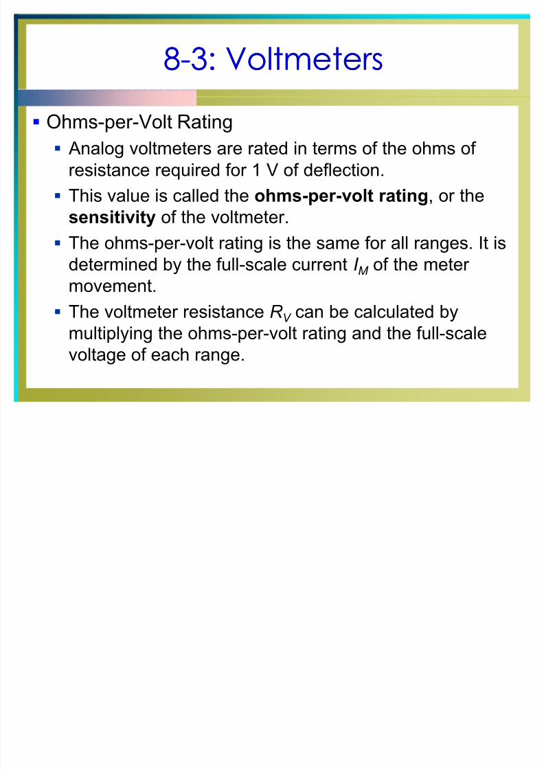
Ohms-per-Volt Rating
Analog voltmeters are rated in terms of the ohms of
resistance required for 1 V of deflection.
This value is called the ohms-per-volt rating, or thesensitivity of the voltmeter.
The ohms-per-volt rating is the same for all ranges. It is
determined by the full-scale current I M of the meter
movement. The voltmeter resistance R V can be calculated by
multiplying the ohms-per-volt rating and the full-scale
voltage of each range.
8/8/2019 Cours d'éléctronique pour les débutants 8
http://slidepdf.com/reader/full/cours-delectronique-pour-les-debutants-8 19/39
88--4: Loading Effect of a Voltmeter 4: Loading Effect of a Voltmeter
When voltmeter resistance is not high enough,
connecting it across a circuit can reduce the measured
voltage.
This effect is called loading down the circuit, because
the measured voltage decreases due to the additional
load current for the meter.
8/8/2019 Cours d'éléctronique pour les débutants 8
http://slidepdf.com/reader/full/cours-delectronique-pour-les-debutants-8 20/39
88--4: Loading Effect of a Voltmeter 4: Loading Effect of a Voltmeter
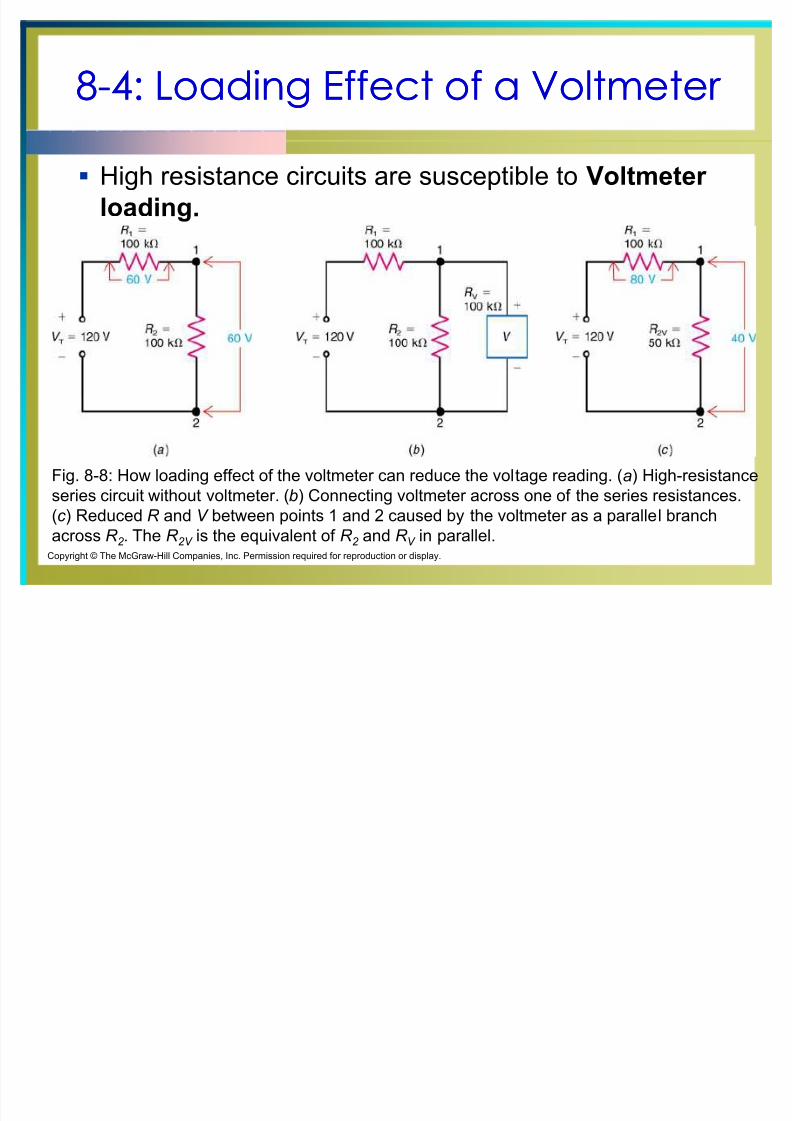
High resistance circuits are susceptible to Voltmeter
loading.
Fig. 8-8: How loading effect of the voltmeter can reduce the voltage reading. (a) High-resistance
series circuit without voltmeter. (b) Connecting voltmeter across one of the series resistances.
(c ) Reduced R and V between points 1 and 2 caused by the voltmeter as a parallel branch
across R 2 . The R 2V is the equivalent of R 2 and R V in parallel.
Copyright © The McGraw-Hill Companies, Inc. Permission required for reproduction or display.
8/8/2019 Cours d'éléctronique pour les débutants 8
http://slidepdf.com/reader/full/cours-delectronique-pour-les-debutants-8 21/39
8/8/2019 Cours d'éléctronique pour les débutants 8
http://slidepdf.com/reader/full/cours-delectronique-pour-les-debutants-8 22/39
88--4: Loading Effect of a Voltmeter 4: Loading Effect of a Voltmeter
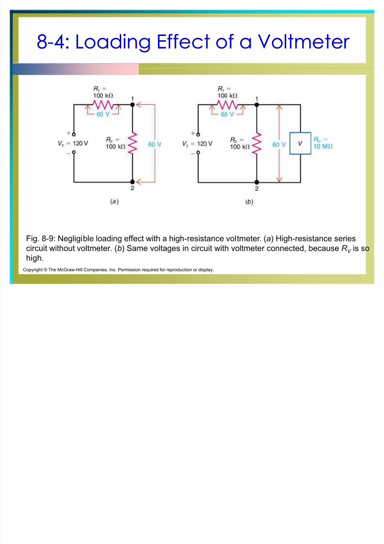
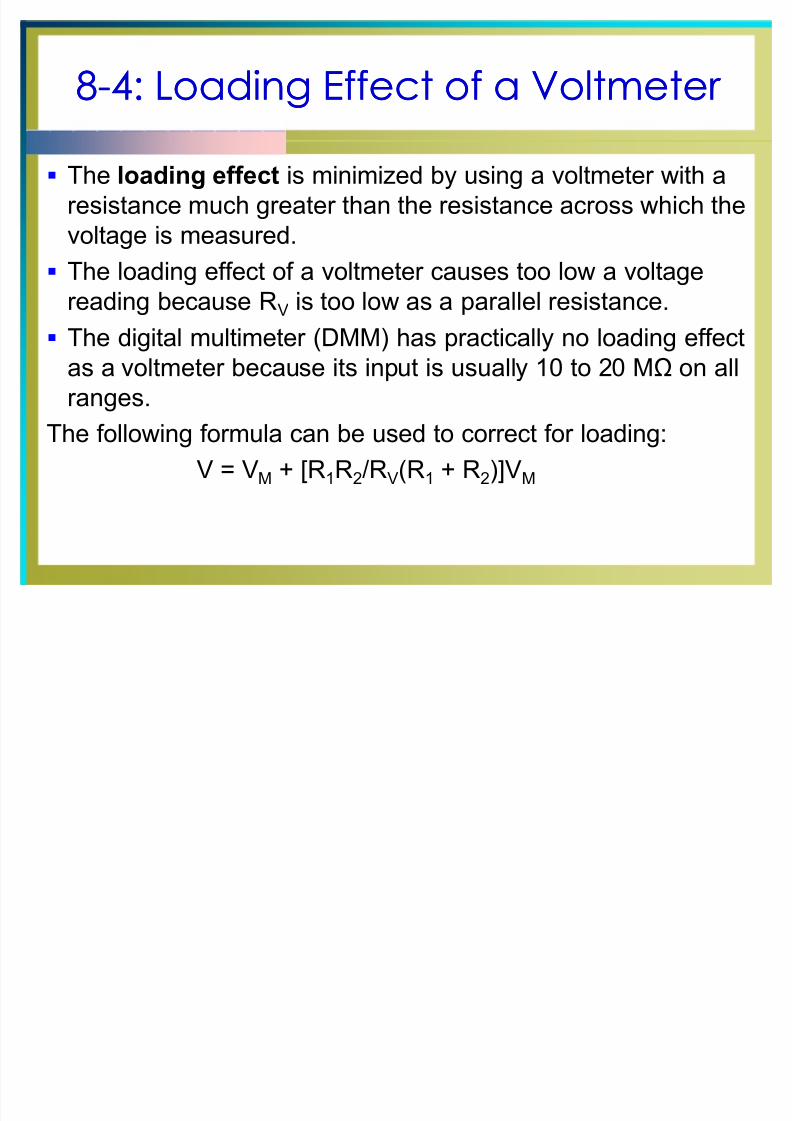
The loading effect is minimized by using a voltmeter with a
resistance much greater than the resistance across which the
voltage is measured.
The loading effect of a voltmeter causes too low a voltagereading because RV is too low as a parallel resistance.
The digital multimeter (DMM) has practically no loading effect
as a voltmeter because its input is usually 10 to 20 M on all
ranges.
The following formula can be used to correct for loading:
V = VM + [R1R2/RV(R1 + R2)]VM
8/8/2019 Cours d'éléctronique pour les débutants 8
http://slidepdf.com/reader/full/cours-delectronique-pour-les-debutants-8 23/39
88--5: Ohmmeters5: Ohmmeters
An ohmmeter consists of an internal battery in series
with the meter movement, and a current limiting
resistance.
Power in the circuit being tested is shut off. Current from the internal battery flows through the
resistance being measured, producing a deflection that
is:
Proportional to the current flow, and Displayed on a back-off scale, with ohm values
increasing to the left as the current backs off from
full-scale deflection.
8/8/2019 Cours d'éléctronique pour les débutants 8
http://slidepdf.com/reader/full/cours-delectronique-pour-les-debutants-8 24/39
8-5: Ohmmeters
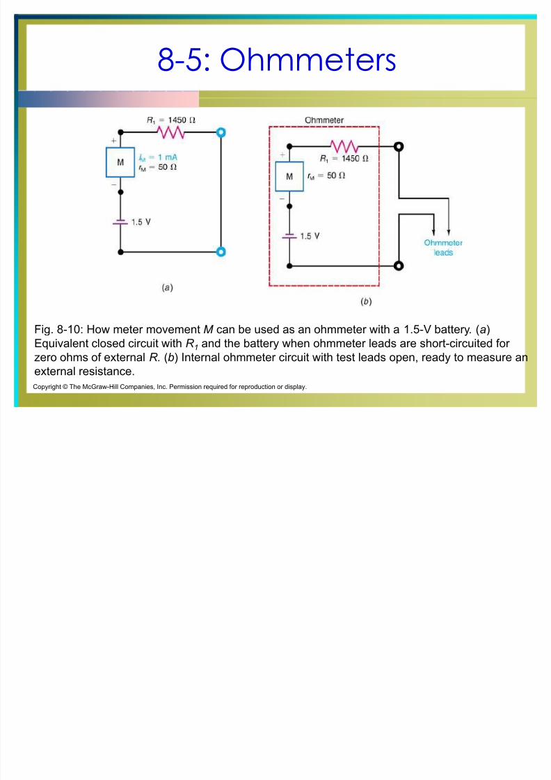
Fig. 8-10: How meter movement M can be used as an ohmmeter with a 1.5-V battery. (a)
Equivalent closed circuit with R 1 and the battery when ohmmeter leads are short-circuited for
zero ohms of external R. (b) Internal ohmmeter circuit with test leads open, ready to measure an
external resistance.
Copyright © The McGraw-Hill Companies, Inc. Permission required for reproduction or display.
8/8/2019 Cours d'éléctronique pour les débutants 8
http://slidepdf.com/reader/full/cours-delectronique-pour-les-debutants-8 25/39
8-5: Ohmmeters
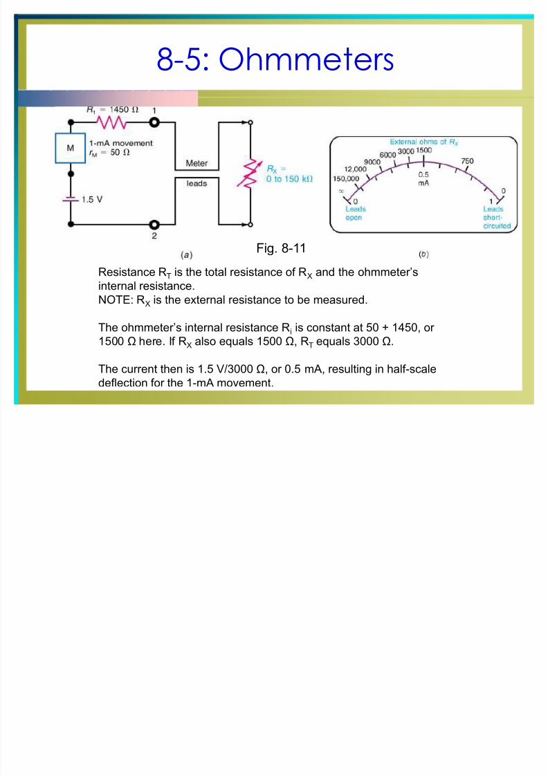
Resistance RT is the total resistance of RX and the ohmmeter¶s
internal resistance.NOTE: RX is the external resistance to be measured.
The ohmmeter¶s internal resistance Ri is constant at 50 + 1450, or
1500 here. If RX also equals 1500 , RT equals 3000 .
The current then is 1.5 V/3000 , or 0.5 mA, resulting in half-scale
deflection for the 1-mA movement.
Fig. 8-11
8/8/2019 Cours d'éléctronique pour les débutants 8
http://slidepdf.com/reader/full/cours-delectronique-pour-les-debutants-8 26/39
88--6: Multimeters6: Multimeters
Multimeters are also called multitesters.
Multimeters are used to measure voltage, current, or
resistance.
Main types of multimeters are:
Volt-ohm-milliammeter (VOM)
Digital multimeter (DMM)
8/8/2019 Cours d'éléctronique pour les débutants 8
http://slidepdf.com/reader/full/cours-delectronique-pour-les-debutants-8 27/39
88--6: Multimeters6: Multimeters
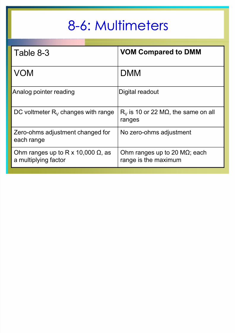
Table 8-3 VOM Compared to DMM
VOM DMM
Analog pointer reading Digital readout
DC voltmeter RV changes with range RV is 10 or 22 M, the same on all
ranges
Zero-ohms adjustment changed for
each range
No zero-ohms adjustment
Ohm ranges up to R x 10,000 , as
a multiplying factor
Ohm ranges up to 20 M; each
range is the maximum
8/8/2019 Cours d'éléctronique pour les débutants 8
http://slidepdf.com/reader/full/cours-delectronique-pour-les-debutants-8 28/39
88--6: Multimeters6: Multimeters
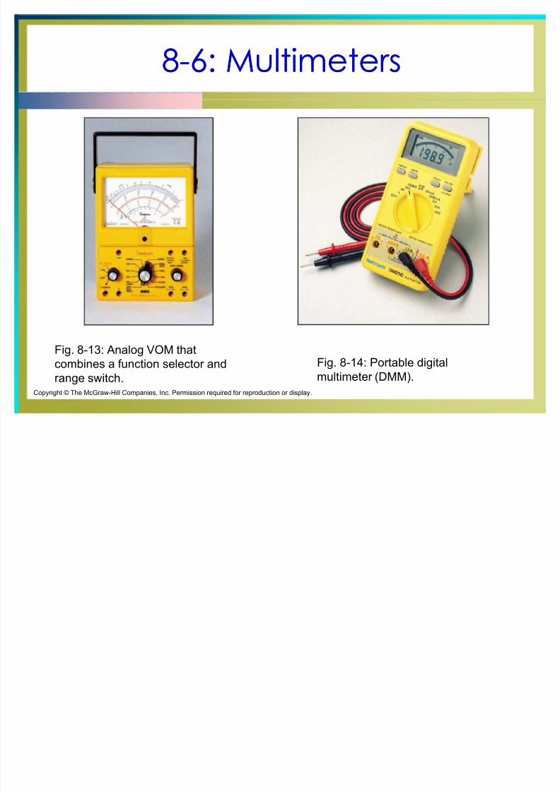
Fig. 8-13: Analog VOM that
combines a function selector and
range switch.
Fig. 8-14: Portable digital
multimeter (DMM).
Copyright © The McGraw-Hill Companies, Inc. Permission required for reproduction or display.
8/8/2019 Cours d'éléctronique pour les débutants 8
http://slidepdf.com/reader/full/cours-delectronique-pour-les-debutants-8 29/39
88--6: Multimeters6: Multimeters
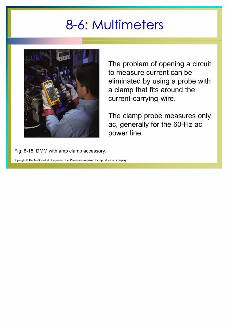
Fig. 8-15: DMM with amp clamp accessory.
Copyright © The McGraw-Hill Companies, Inc. Permission required for reproduction or display.
The problem of opening a circuit
to measure current can be
eliminated by using a probe witha clamp that fits around the
current-carrying wire.
The clamp probe measures only
ac, generally for the 60-Hz ac
power line.
8/8/2019 Cours d'éléctronique pour les débutants 8
http://slidepdf.com/reader/full/cours-delectronique-pour-les-debutants-8 30/39
88--7: Digital Multimeters (DMMs)7: Digital Multimeters (DMMs)
The digital multimeter has become a very popular
test instrument.
The digital value of the measurement is displayed
automatically with decimal point, polarity, and the unitfor V, A, or .
8/8/2019 Cours d'éléctronique pour les débutants 8
http://slidepdf.com/reader/full/cours-delectronique-pour-les-debutants-8 31/39
88--7: Digital Multimeters (DMMs)7: Digital Multimeters (DMMs)
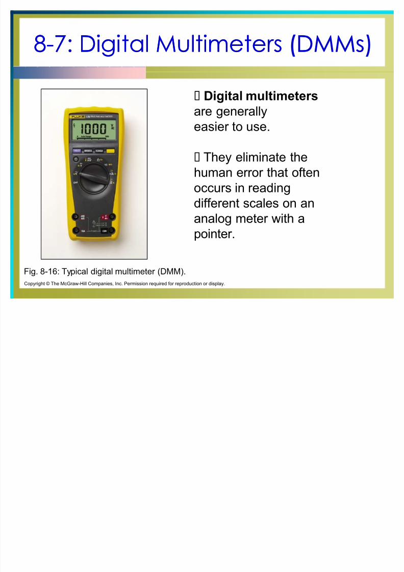
Fig. 8-16: Typical digital multimeter (DMM).
Copyright © The McGraw-Hill Companies, Inc. Permission required for reproduction or display.
Digital multimeters
are generally
easier to use.
They eliminate the
human error that often
occurs in reading
different scales on an
analog meter with apointer.

8/8/2019 Cours d'éléctronique pour les débutants 8
http://slidepdf.com/reader/full/cours-delectronique-pour-les-debutants-8 32/39
88--8: Meter Applications8: Meter Applications
Table 8-4 (next slide) summarizes the main points to
remember when using a voltmeter, ohmmeter, or
milliammeter.
8/8/2019 Cours d'éléctronique pour les débutants 8
http://slidepdf.com/reader/full/cours-delectronique-pour-les-debutants-8 33/39
88--8: Meter Applications8: Meter Applications
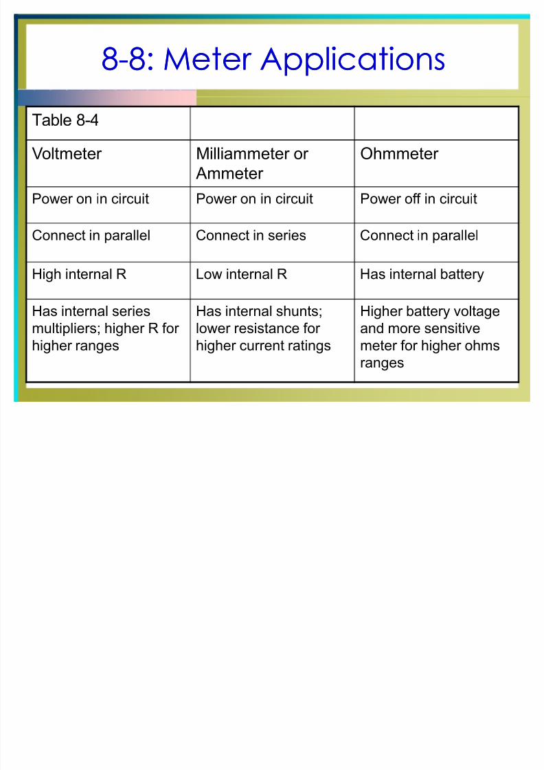
Table 8-4
Voltmeter Milliammeter or
Ammeter
Ohmmeter
Power on in circuit Power on in circuit Power off in circuit
Connect in parallel Connect in series Connect in parallel
High internal R Low internal R Has internal battery
Has internal series
multipliers; higher R for
higher ranges
Has internal shunts;
lower resistance for
higher current ratings
Higher battery voltage
and more sensitive
meter for higher ohms
ranges
8/8/2019 Cours d'éléctronique pour les débutants 8
http://slidepdf.com/reader/full/cours-delectronique-pour-les-debutants-8 34/39
88--8: Meter Applications8: Meter Applications
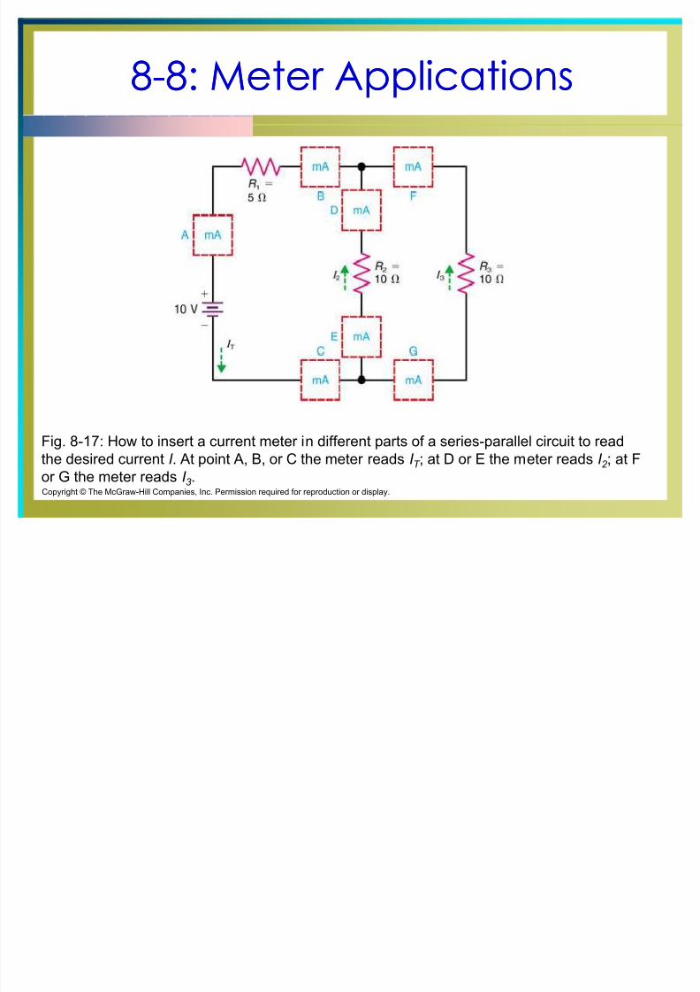
Fig. 8-17: How to insert a current meter in different parts of a series-parallel circuit to read
the desired current I . At point A, B, or C the meter reads I T ; at D or E the meter reads I 2 ; at F
or G the meter reads I 3.
Copyright © The McGraw-Hill Companies, Inc. Permission required for reproduction or display.
8/8/2019 Cours d'éléctronique pour les débutants 8
http://slidepdf.com/reader/full/cours-delectronique-pour-les-debutants-8 35/39
88--8: Meter Applications8: Meter Applications
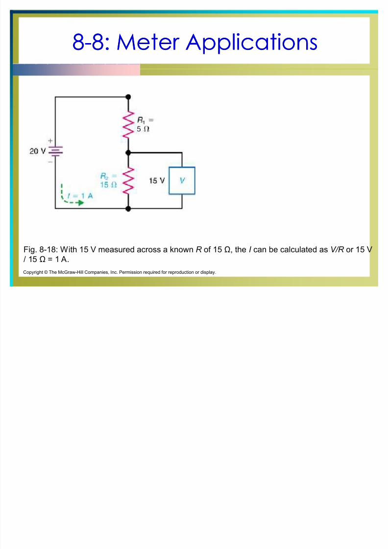
Fig. 8-18: With 15 V measured across a known R of 15 , the I can be calculated as V/R or 15 V
/ 15 = 1 A.
Copyright © The McGraw-Hill Companies, Inc. Permission required for reproduction or display.
8/8/2019 Cours d'éléctronique pour les débutants 8
http://slidepdf.com/reader/full/cours-delectronique-pour-les-debutants-8 36/39
88--8: Meter Applications8: Meter Applications
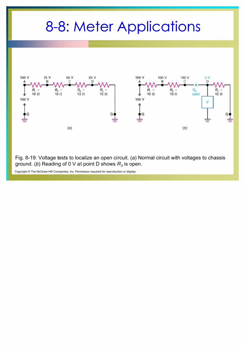
Fig. 8-19: Voltage tests to localize an open circuit. (a) Normal circuit with voltages to chassis
ground. (b) Reading of 0 V at point D shows R 3 is open.
Copyright © The McGraw-Hill Companies, Inc. Permission required for reproduction or display.
8/8/2019 Cours d'éléctronique pour les débutants 8
http://slidepdf.com/reader/full/cours-delectronique-pour-les-debutants-8 37/39
88--9: Checking Continuity9: Checking Continuitywith the Ohmmeter with the Ohmmeter
The ohmmeter is a great tool for checking the
continuity between two points.
When checking for continuity, make sure the
ohmmeter is set on the lowest ohms range.
If continuity exists between two points, the ohmmeter
will read a very low resistance such as zero ohms.
If there is no continuity between two points, the
ohmmeter will read infinite ohms.
8/8/2019 Cours d'éléctronique pour les débutants 8
http://slidepdf.com/reader/full/cours-delectronique-pour-les-debutants-8 38/39
88--9: Checking Continuity9: Checking Continuitywith the Ohmmeter with the Ohmmeter
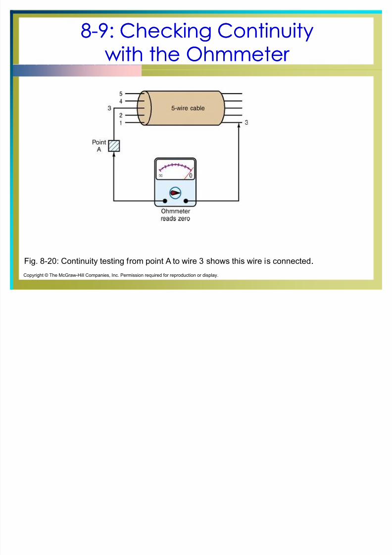
Fig. 8-20: Continuity testing from point A to wire 3 shows this wire is connected.
Copyright © The McGraw-Hill Companies, Inc. Permission required for reproduction or display.
8/8/2019 Cours d'éléctronique pour les débutants 8
http://slidepdf.com/reader/full/cours-delectronique-pour-les-debutants-8 39/39
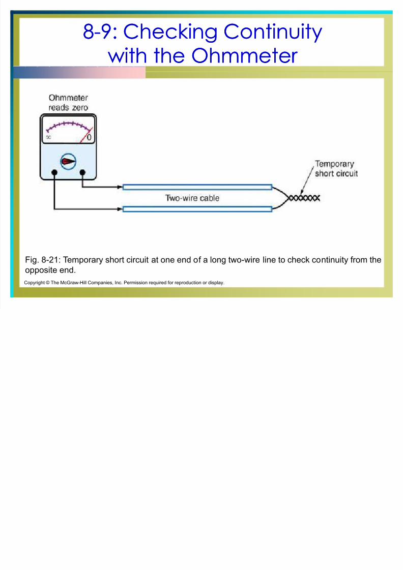
88--9: Checking Continuity9: Checking Continuitywith the Ohmmeter with the Ohmmeter
Fig. 8-21: Temporary short circuit at one end of a long two-wire line to check continuity from the
opposite end.
Copyright © The McGraw-Hill Companies, Inc. Permission required for reproduction or display.