Embed Size (px)
Citation preview
SERVICE MANUAL
DVG-5200SDVG-8300SE
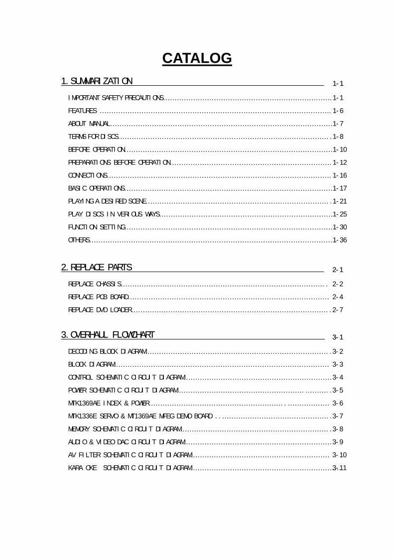
CATALOG
1.SUMMARIZATION
IMPORTANT SAFETY PRECAUTIONS……………………………………………………………….
FEATURES ……………………………………………………………………………………….
ABOUT MANUAL……………………………………………………………………………………
TERMS FOR DISCS………………………………………………………………………………..
BEFORE OPERATION………………………………………………………………………………
PREPARATIONS BEFORE OPERATION…………………………………………………………….
CONNECTIONS…………………………………………………………………………………….
BASIC OPERATIONS………………………………………………………………………………
PLAYING A DESIRED SCENE……………………………………………………………………..
PLAY DISCS IN VERIOUS WAYS…………………………………………………………………
FUNCTION SETTING………………………………………………………………………………
OTHERS……………………………………………………………………………………………
1-1
1-1
1-6
1-7
1-8
1-10
1-12
1-16
1-17
1-21
1-25
1-30
1-36
2.REPLACE PARTS
REPLACE CHASSIS……………………………………………………………………………..
REPLACE PCB BOARD……………………………………………………………………………
REPLACE DVD LOADER…………………………………………………………………………..
2-1
2-2
2-4
2-7
3.OVERHAUL FLOWCHART
DECODING BLOCK DIAGRAM……………………………………………………………………..
BLOCK DIAGRAM…………………………………………………………………………………
CONTROL SCHEMATIC CIRCUIT DIAGRAM……………………………………………………….
POWER SCHEMATIC CIRCUIT DIAGRAM……………………………………………….………..
MTK1369AE INDEX & POWER…………………………………………………..………………
MTK1336E SERVO & MT1369AE MFEG DEMO BOARD ..………………………………………..
MEMORY SCHEMATIC CIRCUIT DIAGRAM………………………………………………………..
AUDIO & VIDEO DAC CIRCUIT DIAGRAM……………………………………………………….
AV FILTER SCHEMATIC CIRCUIT DIAGRAM……………………………………………………
KARAOKE SCHEMATIC CIRCUIT DIAGRAM…………………………………………………………
3-2
3-4
3-5
3-7
3-8
3-9
3-1
3-3
3-6
3-10
3-11

4.IC MATERIAL
MT1369E IC MATERIAL………………………………………………………………………….
CS4340 (AUDIO D/A) IC MATERIAL………..………………………………………………...
AV 3168 (VIDEO) IC MATERIAL ………………………………………………………………
FLASH 29F080 IC MATERIAL…………………………………………………………………...
CONTROL PANEL IC MATERIAL………………………………………………………………….
16M SDRAM IC MATERIAL…………………………………………………………………….....
4-8
4-9
4-12
4-13
4-14
4-1
4-2
2
IMPORTANT SAFETY PRECAUTIONS
CAUTION: TO REDUCE THE RISK OF ELECTRIC SHOCK,DO NOT REMOVE COVER (OR BACK). NO USER-SERVICEABLE PARTS INSIDE. REFER SERVICING TOQUALIFIED SERVICE PERSONNEL.
CAUTIONRISK OF ELECTRIC SHOCK
DO NOT OPEN
The lightning flash with arrowhead symbol,within an equilateral triangle, is intended toalert the user to the presence of uninsulated“dangerous voltage” within the product’senclosure that may be of sufficient magnitude toconstitute a risk of electric shock.
The exclamation point within an equilateraltriangle is intended to alert the user to thepresence of important operating and servicinginstructions in the literature accompanying theappliance.
WARNING : TO REDUCE THE RISK OF FIRE OR ELECTRIC SHOCK, DO NOT EXPOSE THIS APPLIANCE TO RAINOR MOISTURE.
CAUTION : TO PREVENT ELECTRIC SHOCK, MATCH WIDE BLADE OF PLUG TO WIDE SLOT, FULLY INSERT.
IMPORTANT FOR LASER PRODUCTS• LASER : This Digital Video Disc Player employs a Laser System. To ensure proper use of this
product please read this owner’s manual carefully and retain for future reference. Shouldthe unit require maintenance, contact an authorized service location - see serviceprocedure. Use of control adjustments or the performance of procedures other than those specifiedmay result in hazardous radiation exposure. To prevent direct exposure to the laser beam, do not try to open the enclosure. Visiblelaser radiation when open and interlocks defeated. DO NOT STARE INTO THE BEAM.
• DANGER : Visible laser radiation when open and interlock failed ordefeated. Avoid direct exposure to beam.
• CAUTION : Do not open the top cover. There are no user serviceable partsinside the Unit; leave all servicing to qualified service personnel.
CLASS 1
LASER PRODUCT
CAUTION: Any changes or modification in construction of this device which are notexpressly approved by the party responsible for compliance could void theuser’s authority to operate the equipment.
ATTENTION: KEEPING THE STATUS OF STOP IS MORE THAN AN HOUR, THIS SET ENTERSSCREEN SAVE MODE FOR 5 MINUTES AND THEN THE POWER IS SWITCHED OFF.
MACROVISION
This product incorporates copyright protection technology that is protected by method claims ofcertain U.S. patents and other intellectual property rights owned by Macrovision Corporation andother rights owners. Use of this copyright protection technology must be authorized by MacrovisionCorporation, and is intended for home and other limited viewing uses only unless otherwiseauthorized by Macrovision Corporation. Reverse engineering or disassembly is prohibited.
3
IMPORTANT SAFETY PRECAUTIONS
This set has been designed and manufactured toassure personal safety. Improper use can resultin electric shock or fire hazard. The safeguardsincorporated in this unit will protect you if youobserve the following procedures forinstallation, use and servicing. This unit is fullytransistorized and does not contain any partsthat can be repaired by the user.
1 READ INSTRUCTIONSAll the safety and operating instructionsshould be read before the unit is operated.
2 RETAIN INSTRUCTIONSThe safety and operating instructionsshould be retained for future reference.
3 HEED WARNINGSAll warnings on the unit and in the operatinginstructions should be adhered to.
4 FOLLOW INSTRUCTIONSAll operating and use instructions should befollowed.
5 CLEANINGUnplug this unit from the wall outlet beforecleaning. Do not use liquid cleaners oraerosol cleaners. Use a damp cloth forcleaning.
6 ATTACHMENTSDo not use attachments unlessrecommended by the unit’s manufacturer asthey may cause hazards.
7 WATER AND MOISTUREDo not use this unit near water- for example,near a bath tub, wash bowl, kitchen sink orlaundry tub, in a wet basement, or near a
swimming pool.
8 ACCESSORIESDo not place thisunit on anunstable cart,stand, tripod, bracket, or table. The unitmay fall, causing serious injury to achild or adult as well as serious damageto the unit. Use this unit only with a cart,stand , tripod, bracket, or tablerecommended by the manufacturer.
8AA unit and cart combination should bemoved with care. Quick stops, excessiveforce, and uneven surfaces may cause thevideo product and cart combination tooverturn.
9 VENTILATIONSlots and openings in the case areprovided for ventilation to ensure reliableoperation of the unit and to protect it fromoverheating. These openings must not beblocked or covered. These openings mustnot be blocked by placing the unit on abed, sofa, rug, or other similar surface.This unit should never be placed near orover a radiator or heat radiator. This unitshould not be placed in a built-ininstallation such as a bookcase or rackunless proper ventilation is provided or themanufacturer’s instructions have beenadhered to.
10 POWER SOURCESThis unit should be operated only from thetype of power source indicated on themarking label. If you are not sure of thetype of power supply to your home, consult
PORTABLE CART WARNING(symbol provided by RETAC)
4
your video dealer or local power company.For units intended to operate from batterypower, or other sources, refer to theoperating instructions.
11 GROUNDING OR POLARIZATIONThis unit is equipped with a polarizedalternating -current line plug (a plughaving one blade wider than the other).This plug will fit into the power outlet onlyone way.
This is a safety feature. If you are unable toinsert the plug fully into the outlet, tryreversing the plug. If the plug still fails tofit, contact your electrician to replace yourobsolete outlet.To prevent electric shock,do not use this polarized plug with anextension cord, receptacle, or other outletunless the blades can be fully insertedwithout blade exposure. If you need anextension cord, use a polarized cord.
12 POWER-CORD PROTECTIONPower-supply cords should be routed sothat they are not likely to be walked on orpinched by items placed upon or againstthem, paying particular attention to cordsat plugs, convenience receptacles, and thepoint where they exit from the unit.
13 LIGHTNINGFor added protection for this unit during alightning storm, or when it is leftunattended and unused for long periods oftime, unplug it from the wall outlet anddisconnect the antenna or cable system.This will prevent damage to the unit due tolightning and power line surges.
14 DISC TRAYKeep your fingers well clear of the disc asit is closing. It may cause serious personalinjury.
15 OVERLOADINGDo not overload wall outlets of extensioncords as this can result in a risk of fire orelectric shock.
16 OBJECT AND LIQUID ENTRYNever push objects of any kind into thisunit through openings as they may touchdangerous voltage points or “short-out”parts that could result in a fire or electricshock. Never spill liquid of any kind on theunit.
17 BURDENDo not place a heavy object on or step onthe product. The object may fall, causingserious personal injury and seriousdamage to the product.
18 DISCDo not use a cracked, deformed orrepaired disc. These discs are easily brokenand may cause serious personal injury andproduct malfunction.
19 SERVICINGDo not attempt to service this unit yourselfas opening or removing covers may exposeyou to dangerous voltage or other hazards.Refer all servicing to qualified servicepersonnel.
IMPORTANT SAFETY PRECAUTIONS
5
20 DAMAGE REQUIRING SERVICEUnplug this unit from the wall outlet andrefer servicing to qualified servicepersonnel under the following conditions.
A. When the power-supply cord or plug isdamaged.
B. If liquid has been spilled, or objectshave fallen into the unit.
C. If the unit has been exposed to rain orwater.
D. If the unit does not operate normallyby following the operatinginstructions. Adjust only thosecontrols that are covered by theoperating instructions. Improperadjustment of other controls mayresult in damage and will oftenrequire extensive work by a qualifiedtechnician to restore the unit to itsnormal operation.
E. If the product has been dropped or thecabinet has been damaged.
F. When the unit exhibits a distinctchange in performance-this indicates aneed for service.
21 REPLACEMENT PARTSWhen replacement parts are required,have the service technician verify that thereplacements he uses have the samesafety characteristics as the original parts.Use of replacements specified by the unitmanufacturer can prevent fire, electricshock, or other hazards.
22 SAFETY CHECK Upon completion of any service or repairsto this unit, ask the service technician to
perform safety checks recommended bythe manufacturer to determine that theunit is in safe operating condition.
23 WALL OR CEILING MOUNTINGThe product should be mounted to a wallor ceiling only as recommended by themanufacturer.
24 HEATThe product should be situated away fromheat sources such as radiators, heatregisters, stoves, or other products(including amplifiers) that produce heat.
FCC NOTICE : This equipment has been tested and found tocomply with the limits for a Class B digitaldevice, pursuant to part 15 of the FCC Rule.These limits are designed to provide reasonableprotection against harmful interference in aresidential installation. This equipmentgenerates, uses and can radiate radio frequencyenergy and if not installed and used inaccordance with the instructions, may causeharmful interference to radio communications.However, there is no guarantee thatinterference will not occur in a particularinstallation. If this equipment does causeharmful interference to radio or televisionreception; which can be determined by turningthe equipment off and on, the user isencouraged to try to correct the interference byone or more of the following measures:• Reorientate or relocate the receiving antenna.• Increase the separation between the
equipment and receiver.• Connect the equipment to an outlet on a
circuit different from that to which thereceiver is connected.
• Consult the dealer or an experience radio/TVtechnical for help.
IMPORTANT SAFETY PRECAUTIONS
6
FEATURES
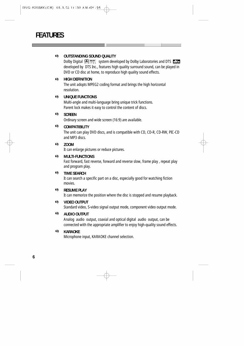
OUTSTANDING SOUND QUALITYDolby Digital system developed by Dolby Laboratories and DTSdeveloped by DTS Inc., features high quality surround sound, can be played inDVD or CD disc at home, to reproduce high quality sound effects.
HIGH DEFINITIONThe unit adopts MPEG2 coding format and brings the high horizontalresolution.
UNIQUE FUNCTIONSMulti-angle and multi-language bring unique trick functions.Parent lock makes it easy to control the content of discs.
SCREENOrdinary screen and wide screen (16:9) are available.
COMPATIBILITYThe unit can play DVD discs, and is compatible with CD, CD-R, CD-RW, PIC-CDand MP3 discs.
ZOOMIt can enlarge pictures or reduce pictures.
MULTI-FUNCTIONSFast forward, fast reverse, forward and reverse slow, frame play , repeat playand program play.
TIME SEARCHIt can search a specific part on a disc, especially good for watching fictionmovies.
RESUME PLAYIt can memorize the position where the disc is stopped and resume playback.
VIDEO OUTPUTStandard video, S-video signal output mode, component video output mode.
AUDIO OUTPUTAnalog audio output, coaxial and optical digital audio output, can beconnected with the appropriate amplifier to enjoy high-quality sound effects.
KARAOKEMicrophone input, KARAOKE channel selection.
7
ABOUT MANUAL
PRINCIPLES FOR WRITING
PLAYABLE DISCS
This manual mainly introduces how to use buttons on the remote control.You may operate the unit if the buttons on the unit have the same or similarnames as or to those on the remote control.
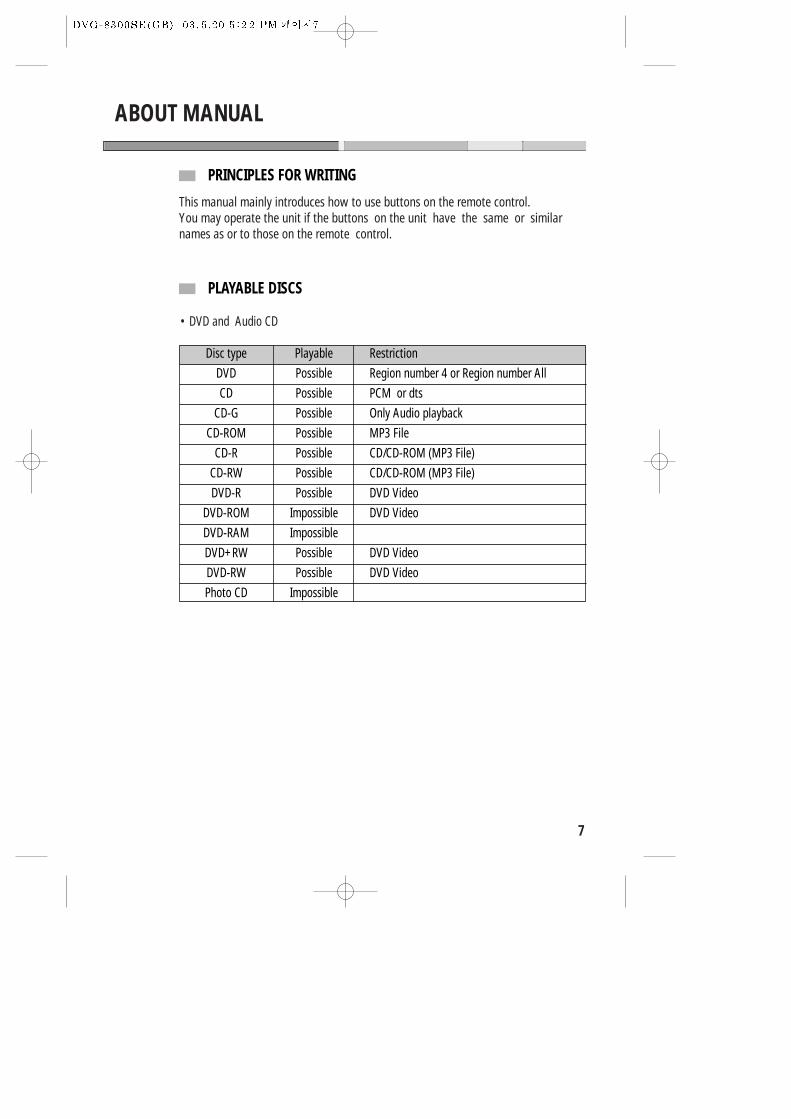
• DVD and Audio CD
Disc type Playable Restriction
DVD Possible Region number 4 or Region number All
CD Possible PCM or dts
CD-G Possible Only Audio playback
CD-ROM Possible MP3 File
CD-R Possible CD/CD-ROM (MP3 File)
CD-RW Possible CD/CD-ROM (MP3 File)
DVD-R Possible DVD Video
DVD-ROM Impossible DVD Video
DVD-RAM Impossible
DVD+RW Possible DVD Video
DVD-RW Possible DVD Video
Photo CD Impossible
8
TITLE
TERMS FOR DISCS
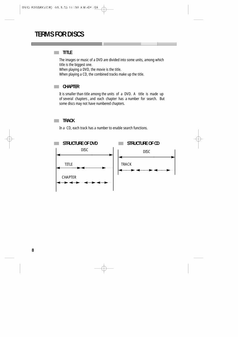
The images or music of a DVD are divided into some units, among whichtitle is the biggest one. When playing a DVD, the movie is the title.When playing a CD, the combined tracks make up the title.
CHAPTERIt is smaller than title among the units of a DVD. A title is made upof several chapters , and each chapter has a number for search. Butsome discs may not have numbered chapters.
TRACKIn a CD, each track has a number to enable search functions.
STRUCTURE OF DVD STRUCTURE OF CDDISC
TITLE
CHAPTER
DISC
TRACK
9
TERMS FOR DISCS
REGION MANAGEMENT INFORMATION
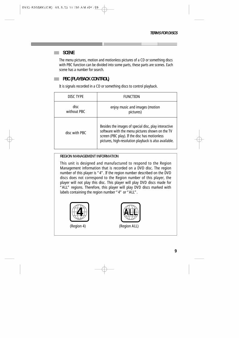
This unit is designed and manufactured to respond to the RegionManagement information that is recorded on a DVD disc. The regionnumber of this player is “4”. If the region number described on the DVDdiscs does not correspond to the Region number of this player, theplayer will not play this disc. This player will play DVD discs made for“ALL” regions. Therefore, this player will play DVD discs marked withlabels containing the region number “4” or “ALL”.
(Region 4) (Region ALL)
4
SCENEThe menu pictures, motion and motionless pictures of a CD or something discswith PBC function can be divided into some parts, these parts are scenes. Eachscene has a number for search.
PBC (PLAYBACK CONTROL) It is signals recorded in a CD or something discs to control playback.
DISC TYPE
discwithout PBC
FUNCTION
enjoy music and images (motionpictures)
disc with PBC
Besides the images of special disc, play interactivesoftware with the menu pictures shown on the TVscreen (PBC play). If the disc has motionlesspictures, high-resolution playback is also available.
10
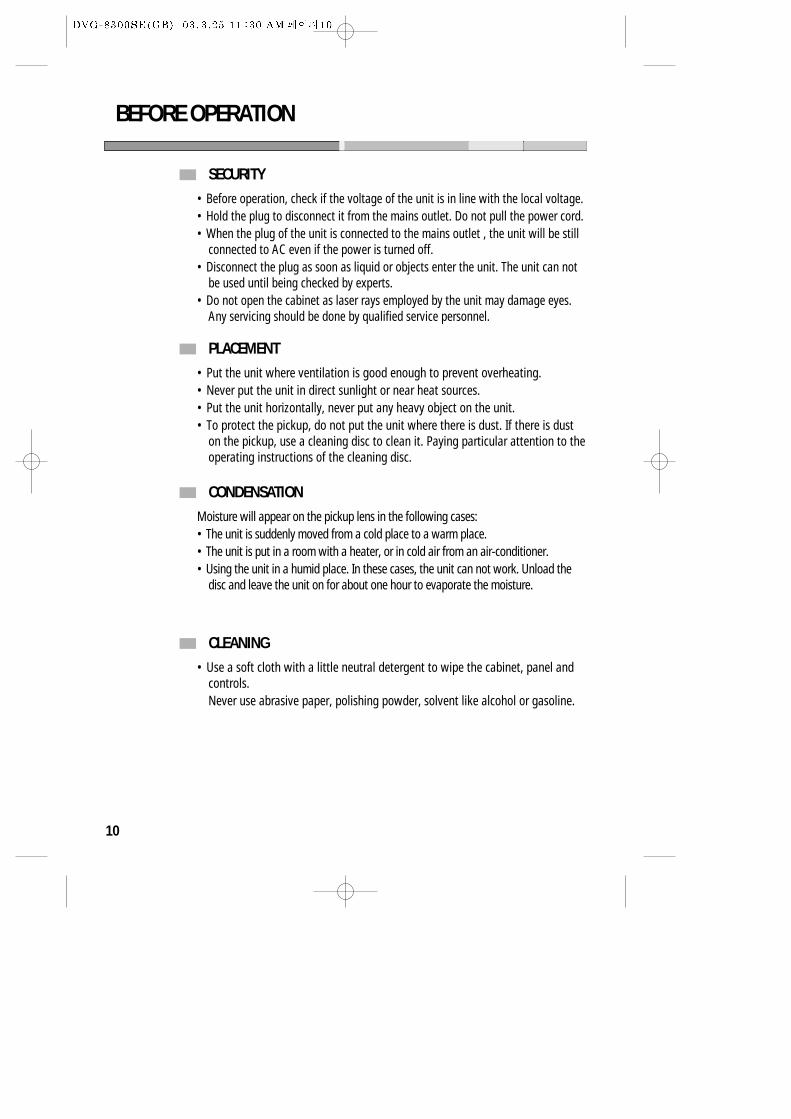
SECURITY
BEFORE OPERATION
• Before operation, check if the voltage of the unit is in line with the local voltage.• Hold the plug to disconnect it from the mains outlet. Do not pull the power cord.• When the plug of the unit is connected to the mains outlet , the unit will be still
connected to AC even if the power is turned off.• Disconnect the plug as soon as liquid or objects enter the unit. The unit can not
be used until being checked by experts.• Do not open the cabinet as laser rays employed by the unit may damage eyes.
Any servicing should be done by qualified service personnel.
PLACEMENT• Put the unit where ventilation is good enough to prevent overheating.• Never put the unit in direct sunlight or near heat sources.• Put the unit horizontally, never put any heavy object on the unit.• To protect the pickup, do not put the unit where there is dust. If there is dust
on the pickup, use a cleaning disc to clean it. Paying particular attention to theoperating instructions of the cleaning disc.
CONDENSATIONMoisture will appear on the pickup lens in the following cases:• The unit is suddenly moved from a cold place to a warm place.• The unit is put in a room with a heater, or in cold air from an air-conditioner.• Using the unit in a humid place. In these cases, the unit can not work. Unload the
disc and leave the unit on for about one hour to evaporate the moisture.
CLEANING• Use a soft cloth with a little neutral detergent to wipe the cabinet, panel and
controls.Never use abrasive paper, polishing powder, solvent like alcohol or gasoline.
11
BEFORE OPERATION
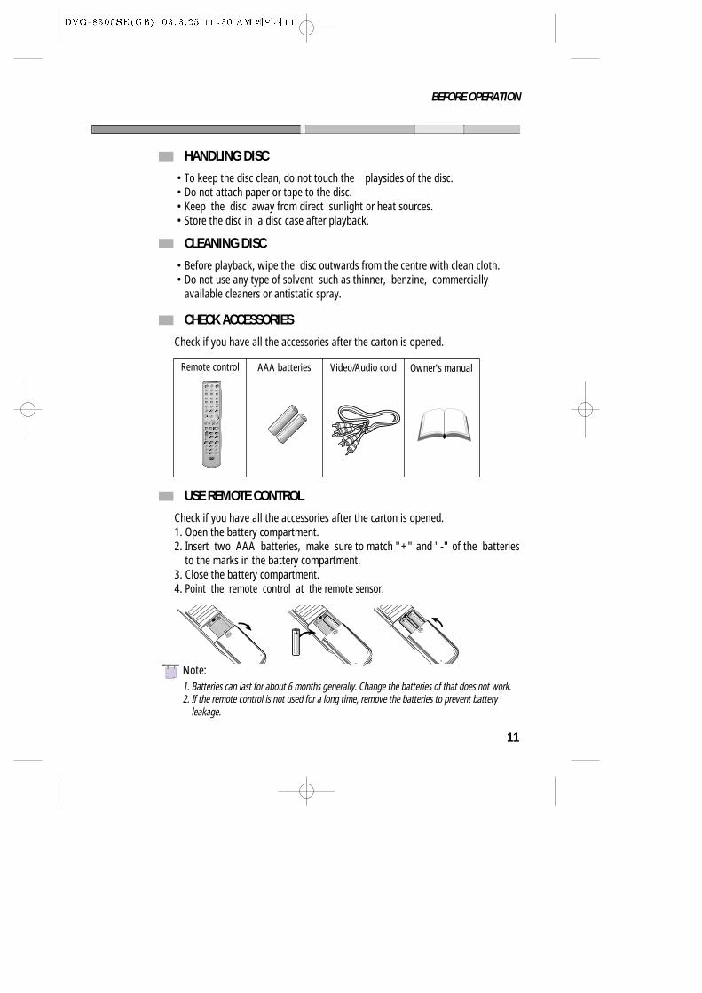
HANDLING DISC
CLEANING DISC
• To keep the disc clean, do not touch the playsides of the disc.• Do not attach paper or tape to the disc.• Keep the disc away from direct sunlight or heat sources.• Store the disc in a disc case after playback.
• Before playback, wipe the disc outwards from the centre with clean cloth.• Do not use any type of solvent such as thinner, benzine, commercially
available cleaners or antistatic spray.
CHECK ACCESSORIES
USE REMOTE CONTROL
Check if you have all the accessories after the carton is opened.
Check if you have all the accessories after the carton is opened.1. Open the battery compartment.2. Insert two AAA batteries, make sure to match "+" and "-" of the batteries
to the marks in the battery compartment. 3. Close the battery compartment.4. Point the remote control at the remote sensor.
Remote control AAA batteries Video/Audio cord Owner’s manual
1. Batteries can last for about 6 months generally. Change the batteries of that does not work.2. If the remote control is not used for a long time, remove the batteries to prevent battery
leakage.
- UM
-4 +
NNote:
12
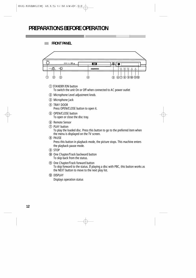
FRONT PANEL
PREPARATIONS BEFORE OPERATION
! STANDBY/ON buttonTo switch the unit On or Off when connected to AC power outlet
@ Microphone Level adjustment knob.
# Microphone Jack
$ TRAY DOORPress OPEN/CLOSE button to open it.
% OPEN/CLOSE buttonTo open or close the disc tray.
^ Remote Sensor& PLAY button
To play the loaded disc. Press this button to go to the preferred item whenthe menu is displayed on the TV screen.
* PAUSEPress this button in playback mode, the picture stops. This machine entersthe playback pause mode.
( STOP) One Chapter/Track backward button
To skip back from the status.
1 One Chapter/Track forward button To skip forward to the status. If playing a disc with PBC, this button works asthe NEXT button to move to the next play list.
2 DISPLAYDisplays operation status
! @ # $ % ^& * () 21
13
PREPARATIONS BEFORE OPERATION
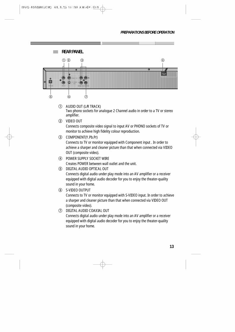
REAR PANEL
! AUDIO OUT (L/R TRACK)Two phono sockets for analogue 2 Channel audio in order to a TV or stereoamplifier.
@ VIDEO OUTConnects composite video signal to input AV or PHONO sockets of TV ormonitor to achieve high fidelity colour reproduction.
# COMPONENT(Y.Pb.Pr)Connects to TV or monitor equipped with Component input . In order toachieve a sharper and cleaner picture than that when connected via VIDEOOUT (composite video).
$ POWER SUPPLY SOCKET WIRECreates POWER between wall outlet and the unit.
% DIGITAL AUDIO OPTICAL OUTConnects digital audio under play mode into an AV amplifier or a receiverequipped with digital audio decoder for you to enjoy the theater-qualitysound in your home.
^ S-VIDEO OUTPUTConnects to TV or monitor equipped with S-VIDEO input. In order to achievea sharper and cleaner picture than that when connected via VIDEO OUT(composite video).
& DIGITAL AUDIO COAXIAL OUTConnects digital audio under play mode into an AV amplifier or a receiverequipped with digital audio decoder for you to enjoy the theater-qualitysound in your home.
L VIDEO OUT
AUDIOOPTICAL
S-VIDEOOUT
R
Y
Pb
Pr
COAXIALCOMPONENT VIDEO
! @ # $
% ^ &
14
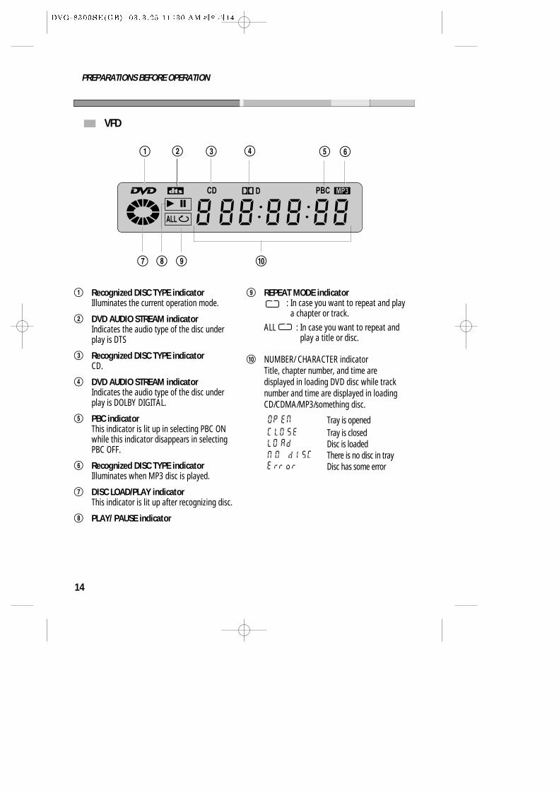
VFD
PREPARATIONS BEFORE OPERATION
ALL
CD D PBC
! @ # $ ^%
& ( )*
! Recognized DISC TYPE indicatorIlluminates the current operation mode.
@ DVD AUDIO STREAM indicatorIndicates the audio type of the disc underplay is DTS
# Recognized DISC TYPE indicatorCD.
$ DVD AUDIO STREAM indicatorIndicates the audio type of the disc underplay is DOLBY DIGITAL.
% PBC indicatorThis indicator is lit up in selecting PBC ONwhile this indicator disappears in selectingPBC OFF.
^ Recognized DISC TYPE indicatorIlluminates when MP3 disc is played.
& DISC LOAD/PLAY indicatorThis indicator is lit up after recognizing disc.
* PLAY/ PAUSE indicator
( REPEAT MODE indicator: In case you want to repeat and playa chapter or track.
ALL : In case you want to repeat andplay a title or disc.
) NUMBER/ CHARACTER indicatorTitle, chapter number, and time aredisplayed in loading DVD disc while tracknumber and time are displayed in loadingCD/CDMA/MP3/something disc.
Tray is openedTray is closedDisc is loadedThere is no disc in trayDisc has some error
15
PREPARATIONS BEFORE OPERATION
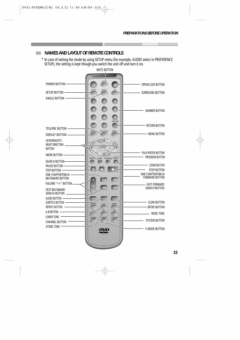
NAMES AND LAYOUT OF REMOTE CONTROLS
POWER BUTTON
DISPLAY BUTTON
ANGLE BUTTON
SETUP BUTTON
TITLE/PBC BUTTON
UP/DOWN/LEFT/RIGHT DIRECTIONBUTTON
SEARCH BUTTON
MARK BUTTON
PAUSE BUTTONSTEP BUTTON
AUDIO BUTTON
REPEAT BUTTON
LOWER TONE
VOLUME “+/-” BUTTON
ONE CHAPTER/TRACKBACKWARD BUTTON
FAST BACKWARDSERACH BUTTON
SUBTITLE BUTTON
A-B BUTTON
ATONIC TONE
OPEN/CLOSE BUTTON
NUMBER BUTTON
MENU BUTTON
RETURN BUTTON
V-MODE BUTTON
STOP BUTTON
RAISE TONE
SYSTEM BUTTON
INTRO BUTTON
ZOOM BUTTON
PROGRAM BUTTON
ONE CHAPTER/TRACKFORWARD BUTTON
PLAY/ENTER BUTTON
MUTE BUTTON
SURROUND BUTTON
FAST FORWARDSERACH BUTTON
SLOW BUTTON
CHANNEL BUTTON
* In case of setting the mode by using SETUP menu (for example, AUDIO select in PREFERENCESETUP), the setting is kept though you switch the unit off and turn it on.
16
CONNECTIONS
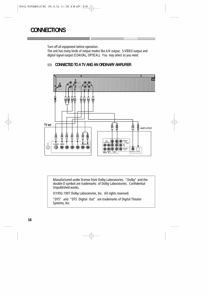
CONNECTED TO A TV AND AN ORDINARY AMPLIFIER
Turn off all equipment before operation.The unit has many kinds of output modes like A/V output, S-VIDEO output anddigital signal output (COAXIAL, OPTICAL). You may select as you need.
L VIDEO OUT
AUDIOOPTICAL
S-VIDEOOUT
R
Y
Pb
Pr
COAXIALCOMPONENT VIDEO
DVDCENTER
WOOFER CDIN
WOOFEROUT
DVDIN
MONITOROUT
VIDEO
COAXIAL IN OPTICAL
R SURROUND L
PrPb
Manufactured under license from Dolby Laboratories. "Dolby" and thedouble-D symbol are trademarks of Dolby Laboratories. ConfidentialUnpublished works.
©1992-1997 Dolby Laboratories, Inc. All rights reserved.
"DTS" and "DTS Digital Out" are trademarks of Digital TheaterSystems, Inc.
17
BASIC OPERATIONS
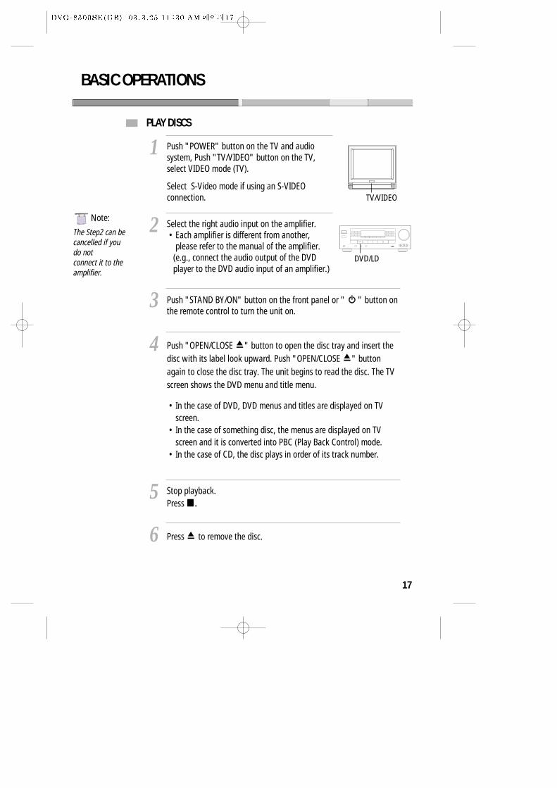
PLAY DISCS
Push "POWER" button on the TV and audiosystem, Push "TV/VIDEO" button on the TV,select VIDEO mode (TV).
Select S-Video mode if using an S-VIDEOconnection.
1
Select the right audio input on the amplifier.• Each amplifier is different from another,
please refer to the manual of the amplifier.(e.g., connect the audio output of the DVDplayer to the DVD audio input of an amplifier.)
2
Push "STAND BY/ON" button on the front panel or " " button onthe remote control to turn the unit on.
3
Push "OPEN/CLOSE " button to open the disc tray and insert thedisc with its label look upward. Push "OPEN/CLOSE " buttonagain to close the disc tray. The unit begins to read the disc. The TVscreen shows the DVD menu and title menu.
• In the case of DVD, DVD menus and titles are displayed on TVscreen.
• In the case of something disc, the menus are displayed on TVscreen and it is converted into PBC (Play Back Control) mode.
• In the case of CD, the disc plays in order of its track number.
4
Stop playback.Press .
5
Press to remove the disc.6
TV/VIDEO
DVD/LD
NNote:
The Step2 can becancelled if youdo notconnect it to theamplifier.
18
BASIC OPERATIONS
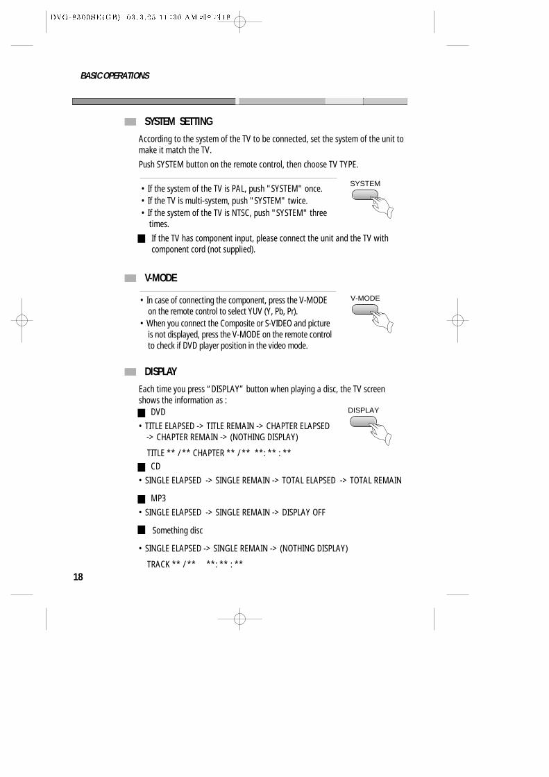
SYSTEM SETTING
V-MODE
• If the system of the TV is PAL, push "SYSTEM" once.• If the TV is multi-system, push "SYSTEM" twice.• If the system of the TV is NTSC, push "SYSTEM" three
times.
According to the system of the TV to be connected, set the system of the unit tomake it match the TV.
Push SYSTEM button on the remote control, then choose TV TYPE.
SYSTEM
V-MODE
If the TV has component input, please connect the unit and the TV withcomponent cord (not supplied).
• In case of connecting the component, press the V-MODEon the remote control to select YUV (Y, Pb, Pr).
• When you connect the Composite or S-VIDEO and pictureis not displayed, press the V-MODE on the remote controlto check if DVD player position in the video mode.
DISPLAY
Each time you press “DISPLAY” button when playing a disc, the TV screenshows the information as :
• TITLE ELAPSED -> TITLE REMAIN -> CHAPTER ELAPSED-> CHAPTER REMAIN -> (NOTHING DISPLAY)
TITLE ** / ** CHAPTER ** / ** **: ** : **
• SINGLE ELAPSED -> SINGLE REMAIN -> (NOTHING DISPLAY)
TRACK ** / ** **: ** : **
DISPLAY
Something disc
DVD
• SINGLE ELAPSED -> SINGLE REMAIN -> TOTAL ELAPSED -> TOTAL REMAIN
CD
• SINGLE ELAPSED -> SINGLE REMAIN -> DISPLAY OFF
MP3
19
BASIC OPERATIONS
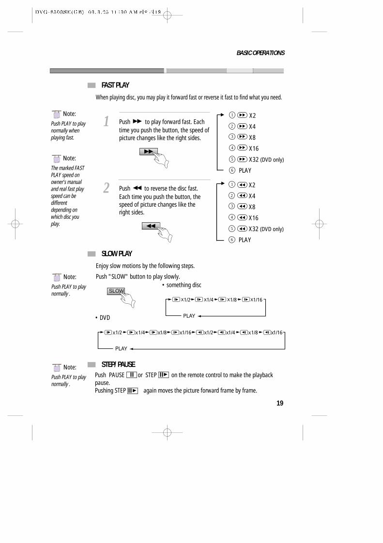
FAST PLAY
When playing disc, you may play it forward fast or reverse it fast to find what you need.
Push to play forward fast. Eachtime you push the button, the speed ofpicture changes like the right sides.
1
Push to reverse the disc fast.Each time you push the button, thespeed of picture changes like theright sides.
2
NNote:
Push PLAY to playnormally .
NNote:
Push PLAY to playnormally .
SLOW PLAY
STEP/ PAUSE
Enjoy slow motions by the following steps.
Push "SLOW" button to play slowly.
SLOW• something disc
• DVD
X2
X4
X8
X16
X32 (DVD only)
PLAY
1
2
3
4
5
6
X2
X4
X8
X16
X32 (DVD only)
PLAY
1
2
3
4
5
6
Push PAUSE or STEP on the remote control to make the playbackpause.Pushing STEP again moves the picture forward frame by frame.
NNote:
Push PLAY to playnormally whenplaying fast.
NNote:
The marked FASTPLAY speed onowner’s manualand real fast playspeed can bedifferentdepending onwhich disc youplay.
20
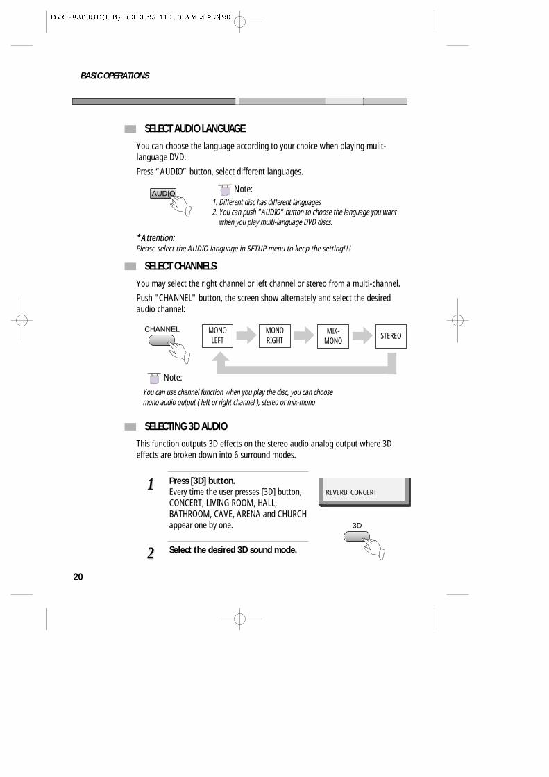
SELECT AUDIO LANGUAGE
You can choose the language according to your choice when playing mulit-language DVD.
Press “AUDIO” button, select different languages.
SELECT CHANNELS
You may select the right channel or left channel or stereo from a multi-channel.
Push "CHANNEL" button, the screen show alternately and select the desiredaudio channel:
1. Different disc has different languages2. You can push "AUDIO" button to choose the language you want
when you play multi-language DVD discs.
CHANNEL
AUDIO
MONOLEFT
MONORIGHT STEREO
MIX-MONO
NNote:
NNote:
BASIC OPERATIONS
SELECTING 3D AUDIO
This function outputs 3D effects on the stereo audio analog output where 3Deffects are broken down into 6 surround modes.
Press [3D] button.Every time the user presses [3D] button,CONCERT, LIVING ROOM, HALL,BATHROOM, CAVE, ARENA and CHURCHappear one by one.
11
Select the desired 3D sound mode.22
REVERB: CONCERT
3D
You can use channel function when you play the disc, you can choosemono audio output ( left or right channel ), stereo or mix-mono
*A*Attention:Please select the AUDIO language in SETUP menu to keep the setting!!!
21
PLAYING A DESIRED SCENE
TO SKIP SCENES IN A DISC
Push to move to next chapter (or track). The current chapter (or track) moves to the next chapter (or track).
1
Push to move to previous chapter (or track). The current chapter (or track) moves to the previous chapter (or track)or first scene of current chapter (or track).
2
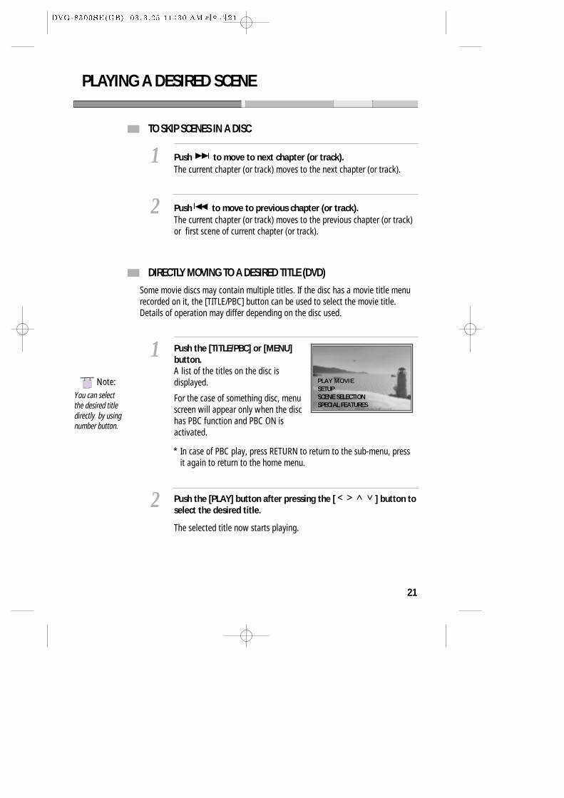
DIRECTLY MOVING TO A DESIRED TITLE (DVD)
Push the [TITLE/PBC] or [MENU]button.A list of the titles on the disc isdisplayed.
For the case of something disc, menuscreen will appear only when the dischas PBC function and PBC ON isactivated.
1
Push the [PLAY] button after pressing the [ ] button toselect the desired title.
The selected title now starts playing.
2
Some movie discs may contain multiple titles. If the disc has a movie title menurecorded on it, the [TITLE/PBC] button can be used to select the movie title.Details of operation may differ depending on the disc used.
PLAY MOVIEPLAY MOVIESETUPSCENE SELECTIONSPECIAL FEATURES
You can selectthe desired titledirectly by usingnumber button.
NNote:
* In case of PBC play, press RETURN to return to the sub-menu, pressit again to return to the home menu.
22
PLAYING A DISC CONTAINING MP3 FILES
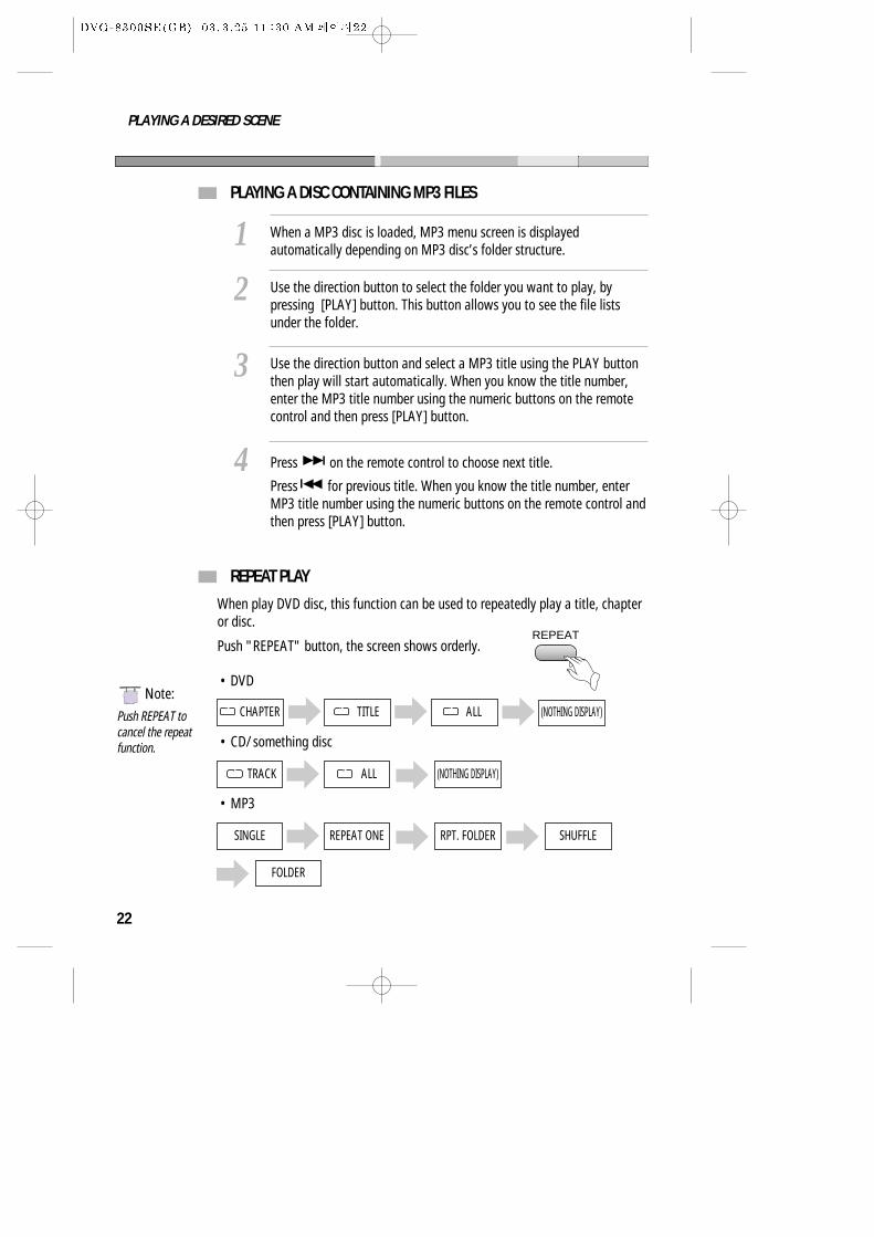
When a MP3 disc is loaded, MP3 menu screen is displayedautomatically depending on MP3 disc’s folder structure.
1Use the direction button to select the folder you want to play, bypressing [PLAY] button. This button allows you to see the file listsunder the folder.
2
Use the direction button and select a MP3 title using the PLAY buttonthen play will start automatically. When you know the title number,enter the MP3 title number using the numeric buttons on the remotecontrol and then press [PLAY] button.
3
Press on the remote control to choose next title.
Press for previous title. When you know the title number, enterMP3 title number using the numeric buttons on the remote control andthen press [PLAY] button.
4
PLAYING A DESIRED SCENE
NNote:
Push REPEAT tocancel the repeatfunction.
REPEAT PLAY
When play DVD disc, this function can be used to repeatedly play a title, chapteror disc.
Push "REPEAT" button, the screen shows orderly.
CHAPTER TITLE ALL
• CD/ something disc
• DVD
TRACK ALL (NOTHING DISPLAY)
(NOTHING DISPLAY)
REPEAT
• MP3
SINGLE REPEAT ONE RPT. FOLDER SHUFFLE
FOLDER
23
PLAYING A DESIRED SCENE
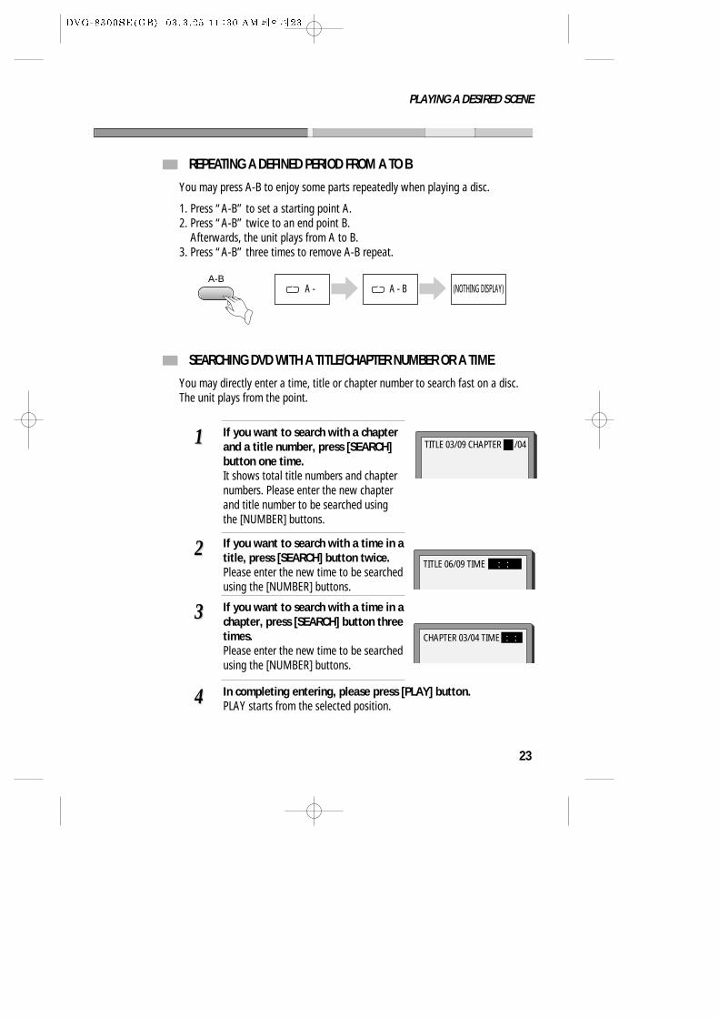
You may press A-B to enjoy some parts repeatedly when playing a disc.
1. Press “A-B” to set a starting point A.2. Press “A-B” twice to an end point B.
Afterwards, the unit plays from A to B.3. Press “A-B” three times to remove A-B repeat.
A-B
REPEATING A DEFINED PERIOD FROM A TO B
You may directly enter a time, title or chapter number to search fast on a disc.The unit plays from the point.
SEARCHING DVD WITH A TITLE/CHAPTER NUMBER OR A TIME
If you want to search with a chapterand a title number, press [SEARCH]button one time.It shows total title numbers and chapternumbers. Please enter the new chapterand title number to be searched usingthe [NUMBER] buttons.
11
If you want to search with a time in atitle, press [SEARCH] button twice.Please enter the new time to be searchedusing the [NUMBER] buttons.
22
If you want to search with a time in achapter, press [SEARCH] button threetimes.Please enter the new time to be searchedusing the [NUMBER] buttons.
33
In completing entering, please press [PLAY] button.PLAY starts from the selected position.44
TITLE 03/09 CHAPTER /04
TITLE 06/09 TIME : :
CHAPTER 03/04 TIME : :
A - A - B (NOTHING DISPLAY)
24
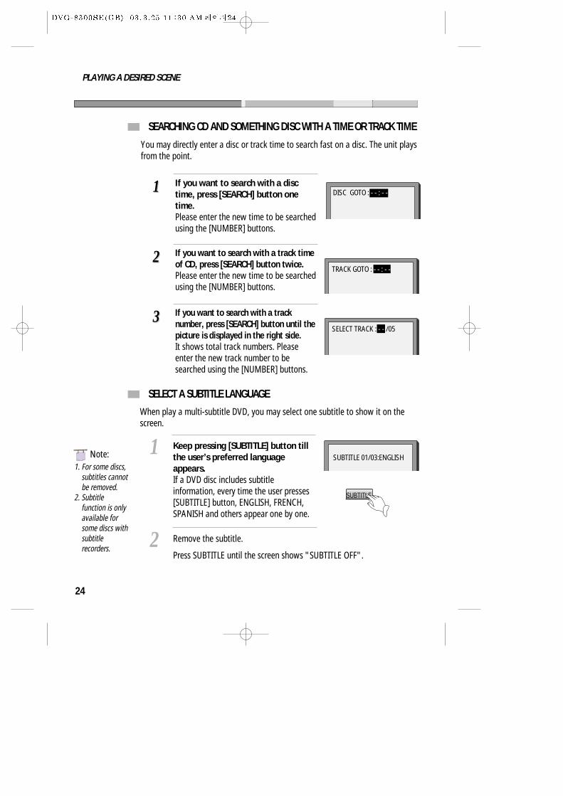
You may directly enter a disc or track time to search fast on a disc. The unit playsfrom the point.
SEARCHING CD AND SOMETHING DISC WITH A TIME OR TRACK TIME
If you want to search with a disctime, press [SEARCH] button onetime.Please enter the new time to be searchedusing the [NUMBER] buttons.
11
If you want to search with a track timeof CD, press [SEARCH] button twice.Please enter the new time to be searchedusing the [NUMBER] buttons.
22TRACK GOTO : - - : - -
If you want to search with a tracknumber, press [SEARCH] button until thepicture is displayed in the right side.It shows total track numbers. Pleaseenter the new track number to besearched using the [NUMBER] buttons.
33SELECT TRACK : - - /05
DISC GOTO : - - : - -
SELECT A SUBTITLE LANGUAGE
When play a multi-subtitle DVD, you may select one subtitle to show it on thescreen.
Keep pressing [SUBTITLE] button tillthe user’s preferred languageappears.If a DVD disc includes subtitleinformation, every time the user presses[SUBTITLE] button, ENGLISH, FRENCH,SPANISH and others appear one by one.
1
Remove the subtitle.
Press SUBTITLE until the screen shows "SUBTITLE OFF".2
SUBTITLE 01/03:ENGLISH
SUBTITLE
1. For some discs,subtitles cannotbe removed.
2. Subtitlefunction is onlyavailable forsome discs withsubtitlerecorders.
NNote:
PLAYING A DESIRED SCENE
25
PLAY DISCS IN VERIOUS WAYS
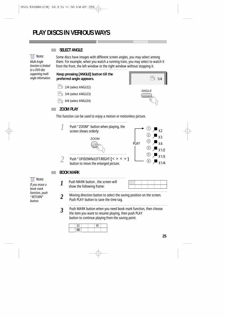
SELECT ANGLE
Some discs have images with different screen angles, you may select amongthem. For example, when you watch a running train, you may select to watch itfrom the front, the left window or the right window without stopping it.
Keep pressing [ANGLE] button till thepreferred angle appears. 1/4
ANGLE2/4 (select ANGLE2)
3/4 (select ANGLE3)
4/4 (select ANGLE4)
Multi Anglefunction is limitedto a DVD discsupporting multiangle information.
NNote:
If you erase abook markfunction, push“RETURN”button.
NNote:
ZOOM PLAY
This function can be used to enjoy a motion or motionless picture.
BOOK MARK
Push MARK button , the screen willshow the following frame:
Push "ZOOM" button when playing, thescreen shows orderly:
1
Push "UP/DOWN/LEFT/RIGHT [ ]button to move the enlarged picture.
2
X2
X3
X4
X1/2
X1/3
X1/4
1
2
3
4
5
6
PLAYZOOM
11
Moving direction button to select the saving position on the screen.Push PLAY button to save the time tag.22
Push MARK button when you need book mark function, then choosethe item you want to resume playing, then push PLAYbutton to continue playing from the saving point.
33
02 0508
26
PLAY DISCS IN VERIOUS WAYS
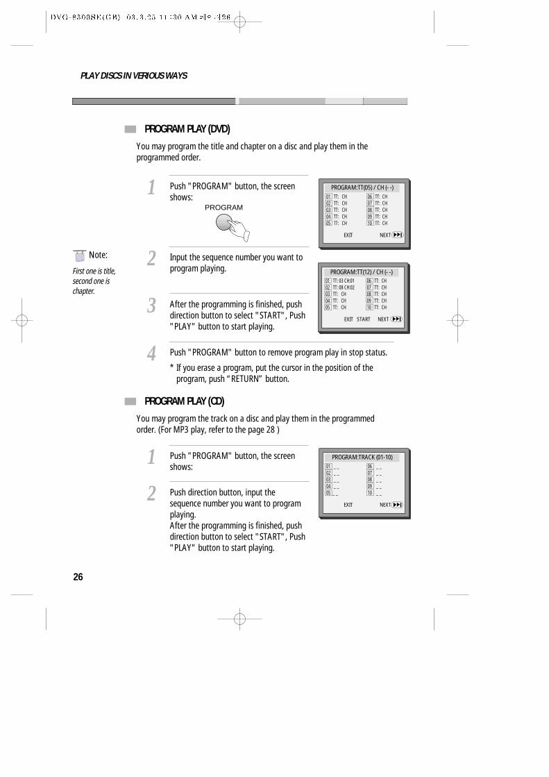
PROGRAM PLAY (DVD)
You may program the title and chapter on a disc and play them in theprogrammed order.
PROGRAM PLAY (CD)
You may program the track on a disc and play them in the programmedorder. (For MP3 play, refer to the page 28 )
Push "PROGRAM" button, the screenshows:
1
Push "PROGRAM" button, the screenshows:
1
Input the sequence number you want toprogram playing.
2
Push direction button, input thesequence number you want to programplaying.After the programming is finished, pushdirection button to select "START", Push"PLAY" button to start playing.
2
After the programming is finished, pushdirection button to select "START", Push"PLAY" button to start playing.
3
Push "PROGRAM" button to remove program play in stop status.
* If you erase a program, put the cursor in the position of theprogram, push “RETURN” button.
4
PROGRAM:TT(05) / CH (- -)
EXIT NEXT
01 TT: CH02 TT: CH03 TT: CH04 TT: CH05 TT: CH
06 TT: CH07 TT: CH08 TT: CH09 TT: CH10 TT: CH
PROGRAM:TT(12) / CH (- -)01 TT: 03 CH:0102 TT: 08 CH:0203 TT: CH04 TT: CH05 TT: CH
06 TT: CH07 TT: CH08 TT: CH09 TT: CH10 TT: CH
EXIT START NEXT
First one is title,second one ischapter.
PROGRAM:TRACK (01-10)
EXIT NEXT
01 _ _02 _ _03 _ _04 _ _05 _ _
06 _ _07 _ _08 _ _09 _ _ 10 _ _
NNote:
PROGRAM
27
PLAY DISCS IN VERIOUS WAYS
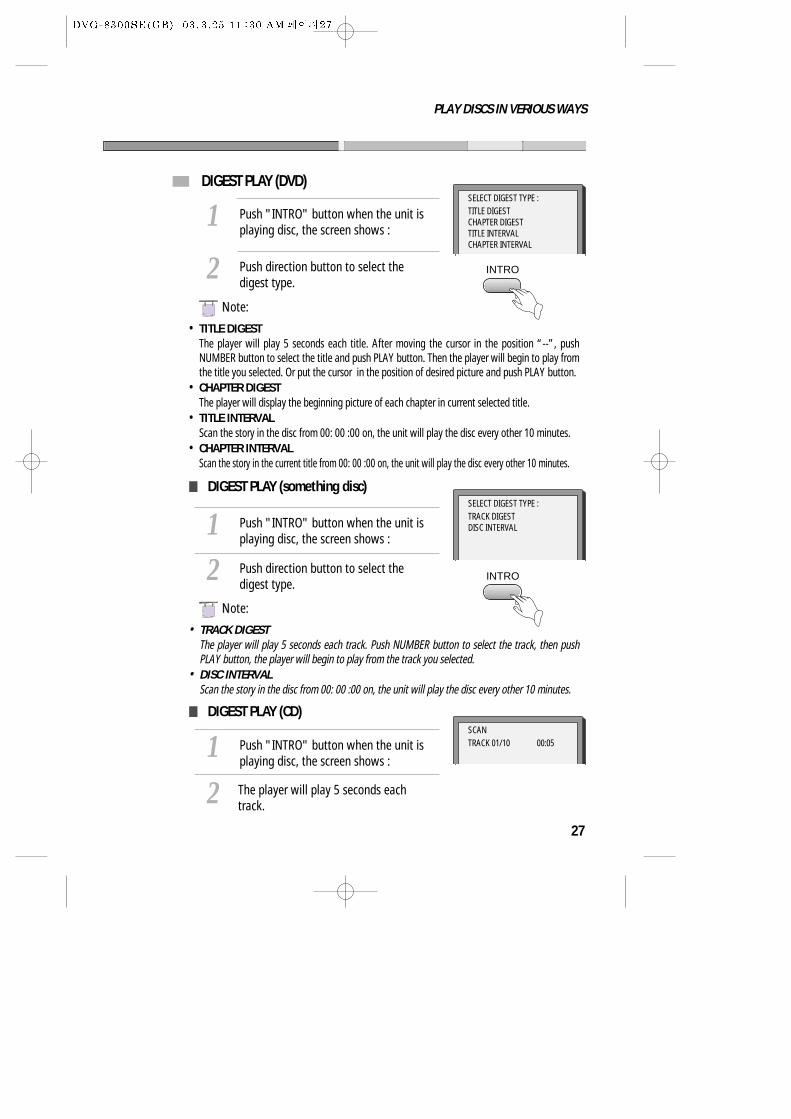
DIGEST PLAY (DVD)
Push "INTRO" button when the unit isplaying disc, the screen shows :
1Push direction button to select thedigest type.
2
SELECT DIGEST TYPE :TITLE DIGESTCHAPTER DIGESTTITLE INTERVALCHAPTER INTERVAL
• TITLE DIGESTThe player will play 5 seconds each title. After moving the cursor in the position “--”, pushNUMBER button to select the title and push PLAY button. Then the player will begin to play fromthe title you selected. Or put the cursor in the position of desired picture and push PLAY button.
• CHAPTER DIGESTThe player will display the beginning picture of each chapter in current selected title.
• TITLE INTERVALScan the story in the disc from 00: 00 :00 on, the unit will play the disc every other 10 minutes.
• CHAPTER INTERVALScan the story in the current title from 00: 00 :00 on, the unit will play the disc every other 10 minutes.
Push "INTRO" button when the unit isplaying disc, the screen shows :
1
Push "INTRO" button when the unit isplaying disc, the screen shows :
12 The player will play 5 seconds each
track.
Push direction button to select thedigest type.
2
SELECT DIGEST TYPE :TRACK DIGESTDISC INTERVAL
SCANTRACK 01/10 00:05
NNote:
• TRACK DIGESTThe player will play 5 seconds each track. Push NUMBER button to select the track, then pushPLAY button, the player will begin to play from the track you selected.
• DISC INTERVALScan the story in the disc from 00: 00 :00 on, the unit will play the disc every other 10 minutes.
NNote:
DIGEST PLAY (something disc)
DIGEST PLAY (CD)
INTRO
INTRO
28
PLAY DISCS IN VERIOUS WAYS
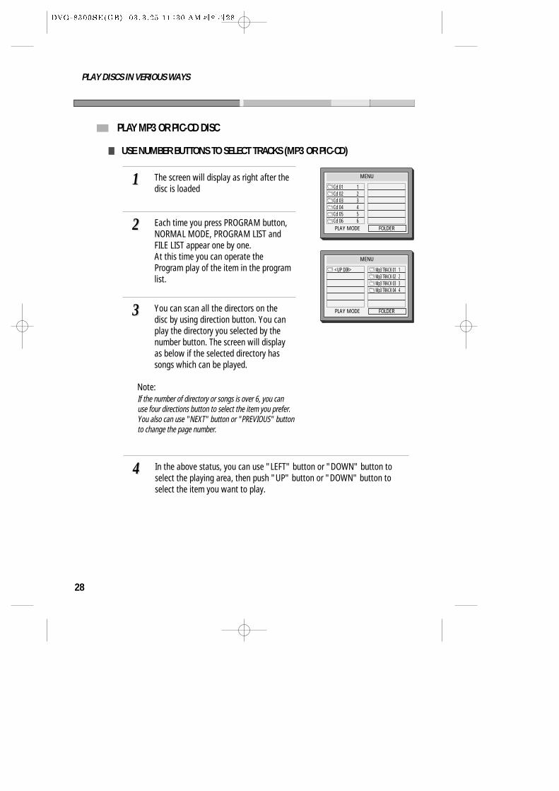
PLAY MP3 OR PIC-CD DISC
USE NUMBER BUTTONS TO SELECT TRACKS (MP3 OR PIC-CD)
The screen will display as right after thedisc is loaded
11
You can scan all the directors on thedisc by using direction button. You canplay the directory you selected by thenumber button. The screen will displayas below if the selected directory hassongs which can be played.
33
Each time you press PROGRAM button,NORMAL MODE, PROGRAM LIST andFILE LIST appear one by one.At this time you can operate theProgram play of the item in the programlist.
22
In the above status, you can use "LEFT" button or "DOWN" button toselect the playing area, then push "UP" button or "DOWN" button toselect the item you want to play.
44
MENU
Cd 01 1Cd 02 2 Cd 03 3 Cd 04 4Cd 05 5Cd 06 6 PLAY MODE FOLDER
MENU
<UP DIR> Mp3 TRACK 01 1Mp3 TRACK 02 2Mp3 TRACK 03 3Mp3 TRACK 04 4
PLAY MODE FOLDER
If the number of directory or songs is over 6, you canuse four directions button to select the item you prefer.You also can use "NEXT" button or "PREVIOUS" buttonto change the page number.
Note:
29
PLAY DISCS IN VERIOUS WAYS
SELECT PLAYING MODE (MP3 OR PIC-CD)
Push direction button to select the play mode area under stop status,then push direction button to select different play mode. These playmodes list as the following :
• Single mode: the player will stop after finished playing the current item• Repeat one mode: repeat the current item• Repeat folder mode: repeat the items in the current directory• Shuffle mode: play items by random• Folder mode: the player will stop after finished playing the whole
directory
11
PLAY PIC-CD BY ZOOM OR ROTATING OPERATING (PIC-CD)
The screen will show "ZOOM 100% " when you push ZOOM button underplaying status, the current picture can be zoomed by push or button,and the screen will also show the zoom ratio of the picture ( ZOOM 100%,ZOOM 125%, ZOOM 150%, ZOOM 200%, ZOOM 75%, ZOOM 50% ). The picturewill restore to the normal status if you push PLAY button under the ZOOM status.
When playing, push "REPEAT" button, you can select "SINGLE","REPEAT ONE", "REPEAT FOLDER" and "FOLDER".
22
30
FUNCTION SETTING
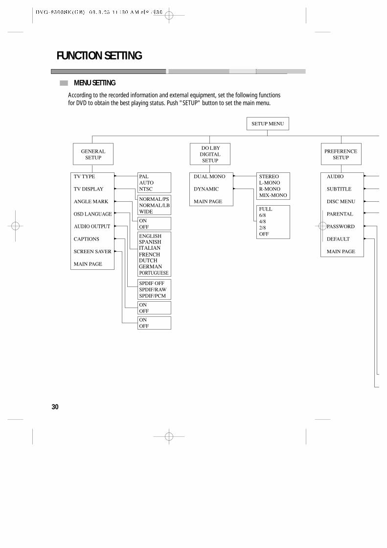
MENU SETTING
According to the recorded information and external equipment, set the following functionsfor DVD to obtain the best playing status. Push "SETUP" button to set the main menu.
31
FUNCTION SETTING
32
FUNCTION SETTING
BASIC NAVIGATION
To navigation through the setting on the screen, use the directionbuttons to scroll through the list of settings and use “PLAY” button toselect the high lighted function.
SETUP MENU
Press the SETUP button to enter the On Screen Display and to exit at anytime. In each of the menus, selecting MAIN PAGE (SETUP menu) willimmediately return you to the initial screen.
GENERAL SETUP
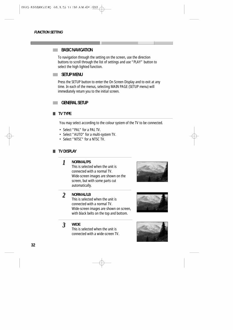
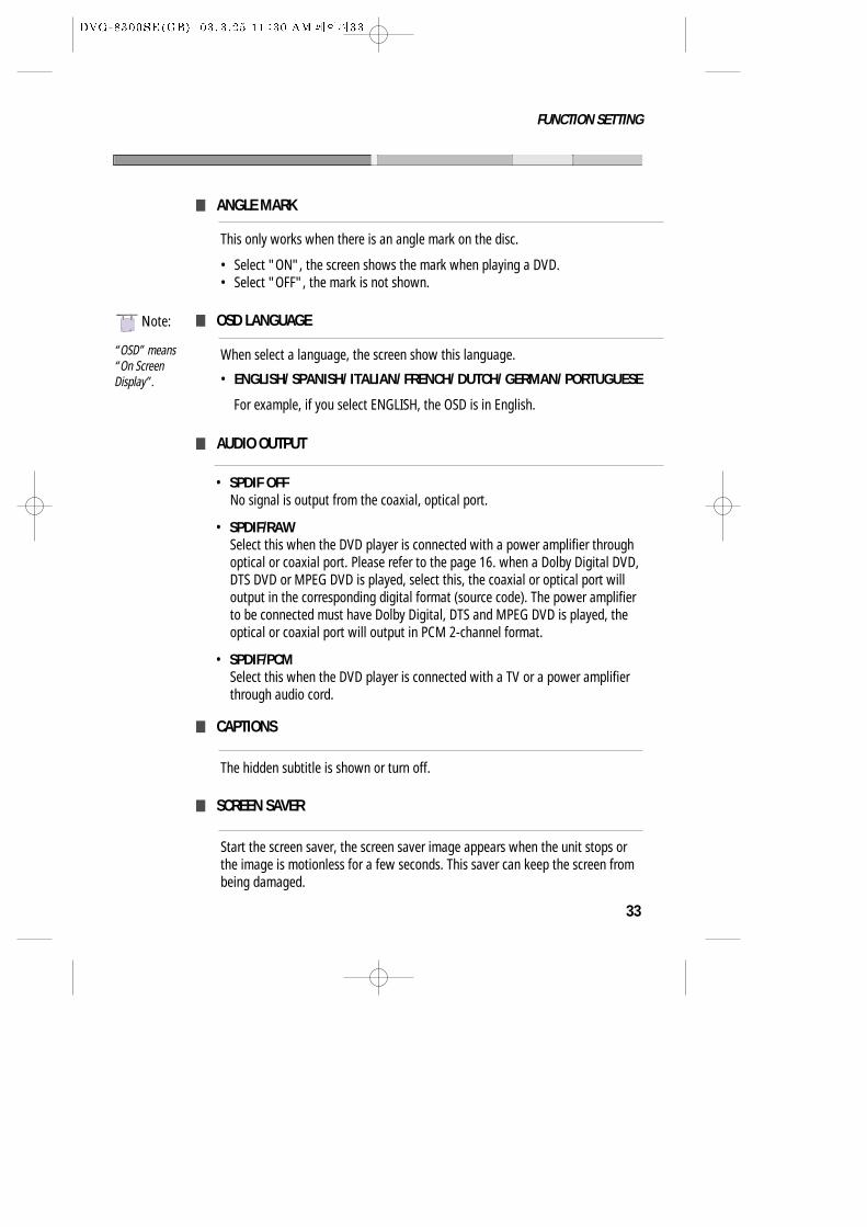
TV DISPLAY
NORMAL/PSThis is selected when the unit isconnected with a normal TV.Wide-screen images are shown on thescreen, but with some parts cutautomatically.
11
NORMAL/LBThis is selected when the unit isconnected with a normal TV.Wide-screen images are shown on screen,with black belts on the top and bottom.
22
WIDEThis is selected when the unit isconnected with a wide-screen TV.
33
TV TYPE
You may select according to the colour system of the TV to be connected.
• Select "PAL" for a PAL TV.• Select "AUTO" for a multi-system TV.• Select "NTSC" for a NTSC TV.
33
FUNCTION SETTING
ANGLE MARK
This only works when there is an angle mark on the disc.
• Select "ON", the screen shows the mark when playing a DVD.• Select "OFF", the mark is not shown.
OSD LANGUAGE
When select a language, the screen show this language.
• ENGLISH/ SPANISH/ ITALIAN/ FRENCH/ DUTCH/ GERMAN/ PORTUGUESE
For example, if you select ENGLISH, the OSD is in English.
CAPTIONS
The hidden subtitle is shown or turn off.
SCREEN SAVER
Start the screen saver, the screen saver image appears when the unit stops orthe image is motionless for a few seconds. This saver can keep the screen frombeing damaged.
AUDIO OUTPUT
• SPDIF OFFNo signal is output from the coaxial, optical port.
• SPDIF/RAWSelect this when the DVD player is connected with a power amplifier throughoptical or coaxial port. Please refer to the page 16. when a Dolby Digital DVD,DTS DVD or MPEG DVD is played, select this, the coaxial or optical port willoutput in the corresponding digital format (source code). The power amplifierto be connected must have Dolby Digital, DTS and MPEG DVD is played, theoptical or coaxial port will output in PCM 2-channel format.
• SPDIF/PCMSelect this when the DVD player is connected with a TV or a power amplifierthrough audio cord.
“OSD” means“On ScreenDisplay”.
NNote:
34
FUNCTION SETTING
DOLBY DIGITAL SETUP
DUAL MONO
This is the output mode of the L and R signals of the set audio output. If it is set to"MIX MONO", the function only works when the DVD being played is 2.0-channel.
• LT/RTChoose this function when play the disc with DOLBY PRO LOGIC stereo function,this model can decode this disc, let you enjoy the perfect drama at home.
• STEREOChoose this option, the audio output should be dummy stereo signal.
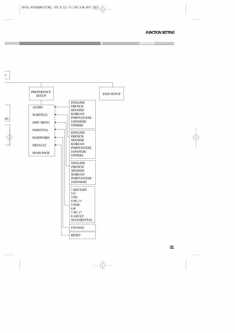
PREFERENCE SETUP
AUDIO
• Selecting an audio language.Set it as the preferred audio language. In case the audio language is set andrecorded in the DISC, it is automatically played in the set language in everyplaying. For example, English is set and recorded as audio language in theDISC, it is played in English.
SUBTITLE
• Selecting Subtitle language.Please set it as the preferred language. In case the subtitle language is set andrecorded in the DISC, it is automatically played in the set language in everyplaying. For example, English is set and recorded as subtitle language in theDISC, it is played in English.
DYNAMIC
When the compression mode is set to "LINE OUT", this is selected to adjust linearcompression rate to obtain the different compression results of the signals.
35
FUNCTION SETTING
DISC MENU
• Selecting Disc Menu language.Please set it as the preferred DISC MENU language. In case the DISC MENUlanguage is set and recorded in the DISC, it is automatically played in the setlanguage in every playing. For example, English is set and recorded as a DISCMENU language in the DISC, it is played in English.
PARENTAL
The content of a disc with lock function is evaluated by grades. You can selectan age grade as your need.
Example: Select “KID SAFE”, the scenes of violence inadvisable to children are not played.
For adults, the screen suggests you enter the code after pushing “PLAY” button, you can watch if the code is right.
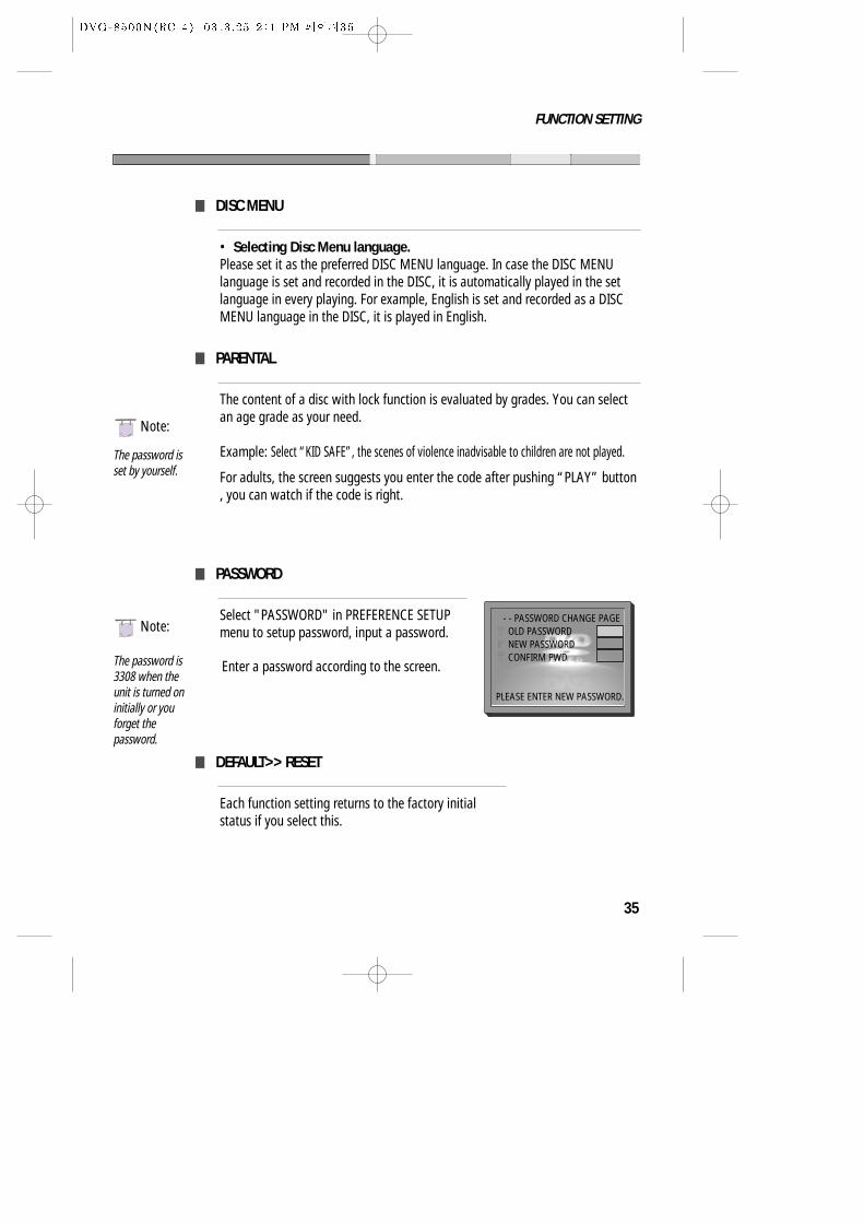
PASSWORD
Select "PASSWORD" in PREFERENCE SETUPmenu to setup password, input a password.
DEFAULT>> RESET
Each function setting returns to the factory initialstatus if you select this.
The password isset by yourself.
The password is3308 when theunit is turned oninitially or youforget thepassword.
Enter a password according to the screen.
NNote:
NNote:- - PASSWORD CHANGE PAGE OLD PASSWORDNEW PASSWORDCONFIRM PWD
PLEASE ENTER NEW PASSWORD.
36
OTHERS
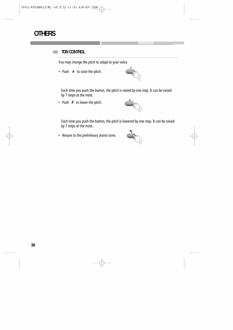
TON CONTROL
You may change the pitch to adapt to your voice
• Push to raise the pitch.
Each time you push the button, the pitch is raised by one step. It can be raisedby 7 steps at the most.
• Push to lower the pitch.
Each time you push the button, the pitch is lowered by one step. It can be raisedby 7 steps at the most.
• Retune to the preliminary atonic-tone.
#
b
b
37
OTHERS
TROUBLESHOOTING
If you experience the following problems while using the unit, this troubleshootingguide can help you.
• NO SOUND
- Check if the unit is connected securely.- Make sure you operate the TV or amplifier correctly.
• NO IMAGE , IMAGE ROLLS AND NO COLOR
- Check if the unit is connected securely.- Make sure you operate the TV correctly.- Make sure you set the color system correctly.
• BAD SOUND QUALITY
- Make sure the audio output mode is set correctly.- Make sure the audio connection between the unit and amplifier is right.
• DISC CAN NOT BE PLAYED
- There is no disc in the unit.- Insert the disc on the disc tray properly with the label side up.- Clean the disc.- Moisture has condensed in the unit. Remove the disc and leave the unit on for about one hour.
• NO PHONE SOUND
- Switch on the microphone.- Turn the MIC LEVEL away knob clockwise.
• SCREAMING
- Keep the phone far away from the speaker- Turn down the volume- Turn down the volume of phone and echo.
• REMOTE CONTROL DOES NOT WORK
- Remove barriers between the remote control and the unit.- Replace the batteries with new ones.- Point the remote control at the remote control sensor of the unit.
• ATTENTION : KEEPING THE STATUS OF STOP IS MORE THAN AN HOUR, THIS SET ENTERSSCREEN SAVE MODE FOR 5 MINUTES AND THEN THE POWER IS SWITCHED OFF.
38
OTHERS
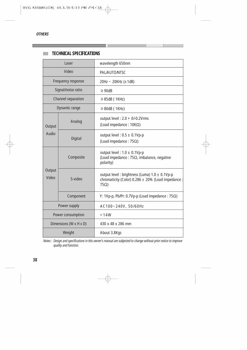
Laser
Video
Frequency response
Signal/noise ratio
output level : 2.0 + 0/-0.2Vrms
(Load impedance : 10KΩ)
output level : 0.5 ± 0.1Vp-p
(Load impedance : 75Ω)
output level : 1.0 ± 0.1Vp-p(Load impedance : 75Ω, imbalance, negativepolarity)
output level : brightness (Luma) 1.0 ± 0.1Vp-pchromaticity (Color) 0.286 ± 20% (Load impedance :75Ω)
AC100~240V, 50/60Hz
<14W
About 3.8Kgs
wavelength 650nm
PAL/AUTO/NTSC
20Hz ~ 20KHz (±1dB)
≥ 90dB
≥ 85dB ( 1KHz)
≥ 80dB ( 1KHz)
Channel separation
Dynamic range
Output
Audio
Output
Video
Analog
Digital
Composite
S-video
Power supply
Component
Power consumption
Dimensions (W x H x D)
Weight
430 x 48 x 286 mm
Notes : Design and specifications in this owner’s manual are subjected to change without prior notice to improvequality and function.
Y: 1Vp-p, Pb/Pr: 0.7Vp-p (Load impedance : 75Ω)
TECHNICAL SPECIFICATIONS
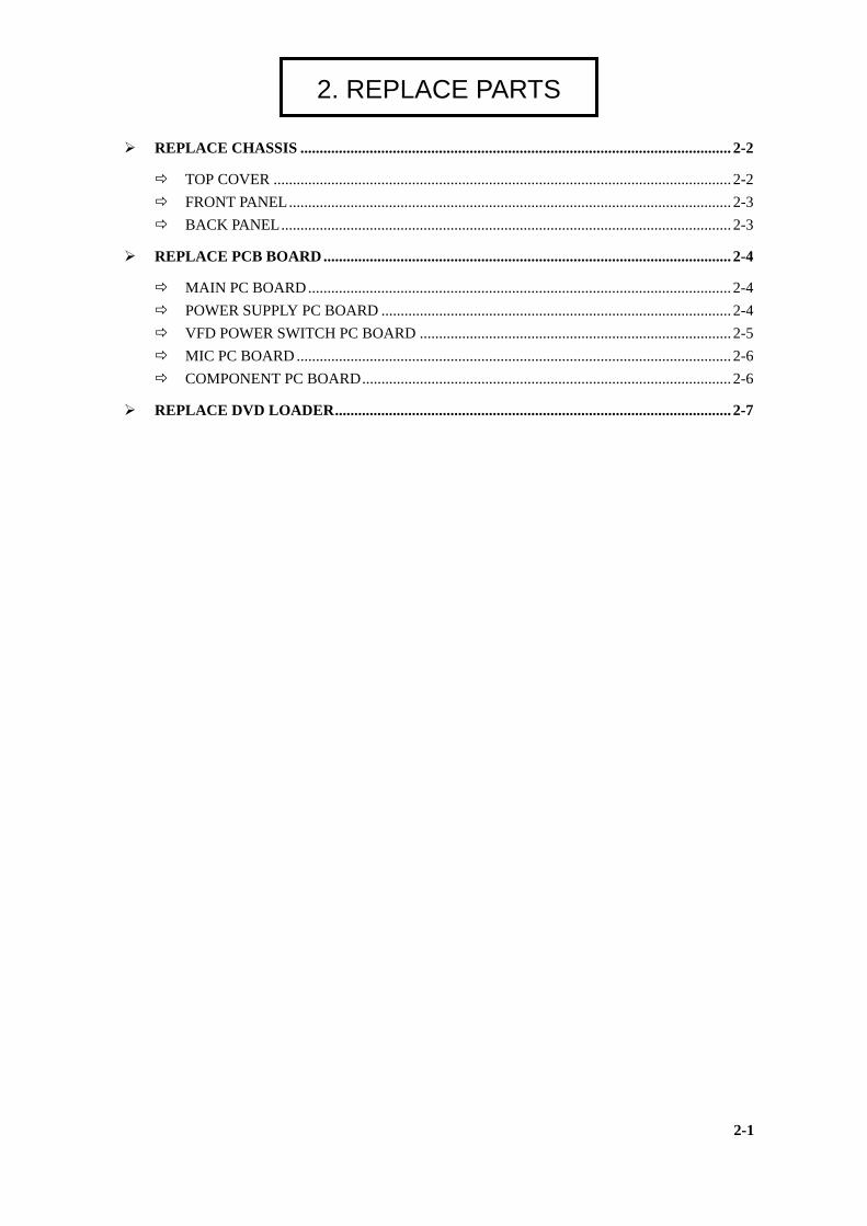
REPLACE CHASSIS ..
TOP COVER ......... FRONT PANEL..... BACK PANEL.......
REPLACE PCB BOAR
MAIN PC BOARD POWER SUPPLY P VFD POWER SWIT MIC PC BOARD ... COMPONENT PC
REPLACE DVD LOAD
2. REPLACE PARTS
.............................................................................................................. 2-2
.............................................................................................................. 2-2
.............................................................................................................. 2-3
.............................................................................................................. 2-3
D .......................................................................................................... 2-4
.............................................................................................................. 2-4 C BOARD ........................................................................................... 2-4 CH PC BOARD ................................................................................. 2-5
.............................................................................................................. 2-6 BOARD................................................................................................ 2-6
ER....................................................................................................... 2-7
2-1
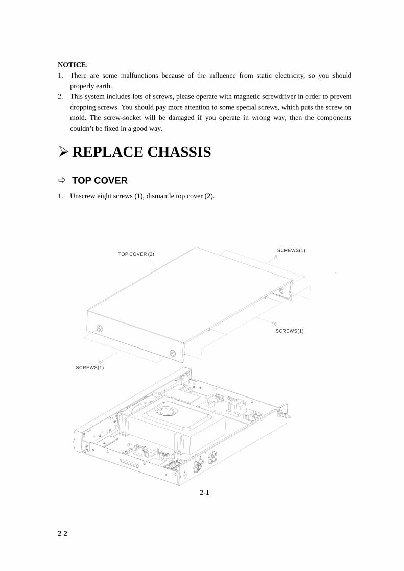
NOTICE: 1. There are some malfunctions because of the influence from static electricity, so you should
properly earth. 2. This system includes lots of screws, please operate with magnetic screwdriver in order to prevent
dropping screws. You should pay more attention to some special screws, which puts the screw on mold. The screw-socket will be damaged if you operate in wrong way, then the components couldn’t be fixed in a good way.
REPLACE CHASSIS
TOP COVER 1. Unscrew eight screws (1), dismantle top cover (2).
SCREWS(1)TOP COVER (2)
SCREWS(1)
SCREWS(1)
2-1
2-2
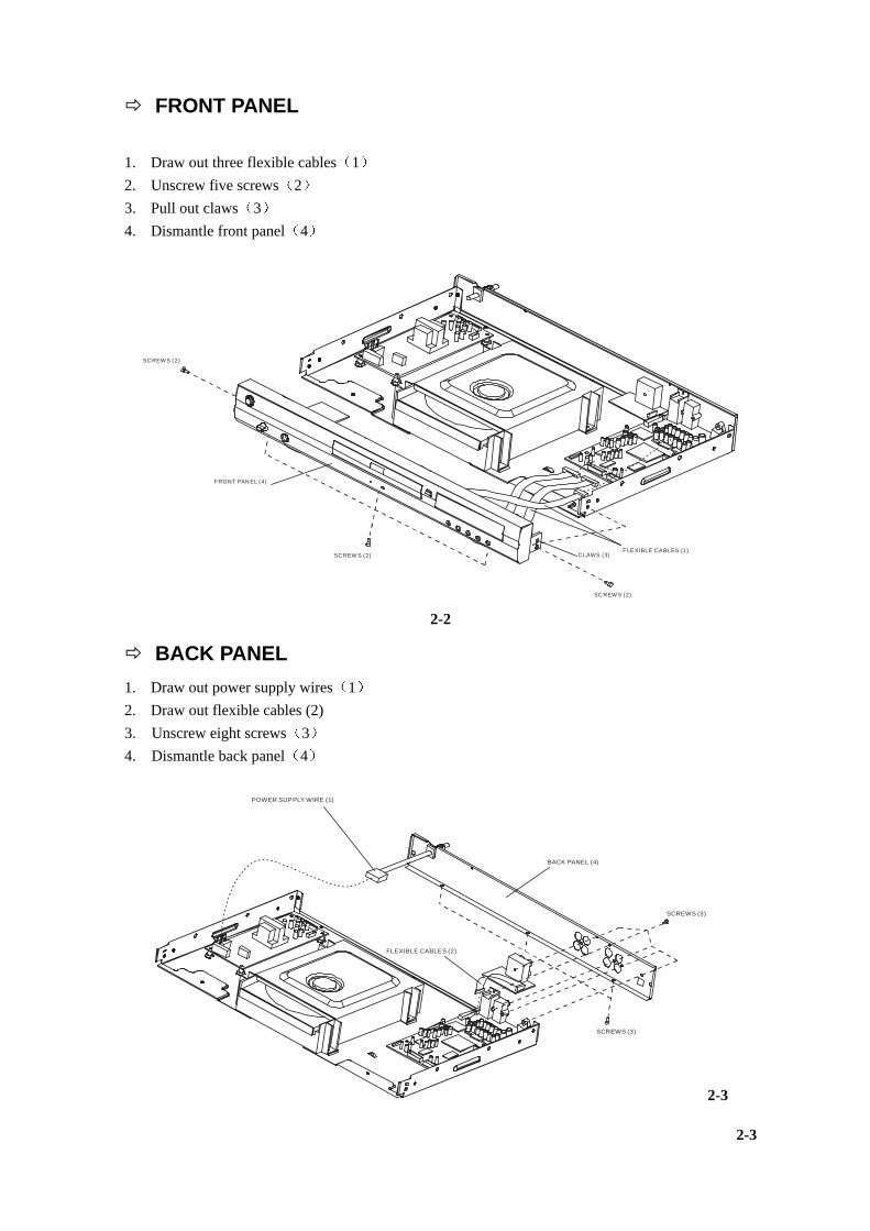
FRONT PANEL 1. Draw out three flexible cables 1 2. Unscrew five screws 2 3. Pull out claws 3 4. Dismantle front panel 4
SC REW S (2)
FRONT PAN EL (4)
SC REW S (2)
SC REW S (2)
FLE XIBLE CA BLES (1)CLAWS (3)
2-2
BACK PANEL 1. Draw out power supply wires 1 2. Draw out flexible cables (2) 3. Unscrew eight screws 3 4. Dismantle back panel 4
SCREWS (3)
BACK PANEL (4)
POWER SUPPLY WIRE (1)
SCREWS (3)
FLEXIBLE CABLES (2)
2-3
2-3
REPLACE PCB BOARD
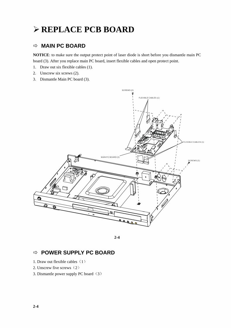
MAIN PC BOARD NOTICE: to make sure the output protect point of laser diode is short before you dismantle main PC board (3). After you replace main PC board, insert flexible cables and open protect point. 1. Draw out six flexible cables (1). 2. Unscrew six screws (2). 3. Dismantle Main PC board (3).
MAIN PC BOARD (3)
SCREWS (2)
FLEXIBLE CABLES (1)
FLEXIBLE CABLES (1)
SCREWS (2)
2-4
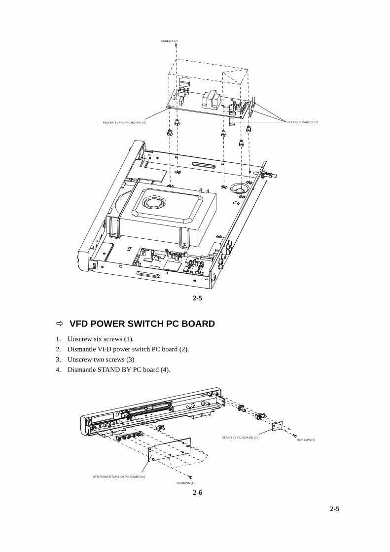
POWER SUPPLY PC BOARD 1. Draw out flexible cables 1 2. Unscrew five screws 2 3. Dismantle power supply PC board 3
2-4
FLEXIBLE CABLES (1)
SCREWS (2)
POWER SUPPLY PC BOARD (3)
2-5
VFD POWER SWITCH PC BOARD 1. Unscrew six screws (1). 2. Dismantle VFD power switch PC board (2). 3. Unscrew two screws (3) 4. Dismantle STAND BY PC board (4).
VFD POWER SWITCH PC BOARD (2)
STAND BY PC BOARD (4)
SCREWS (1)
SCREWS (3)
2-6
2-5
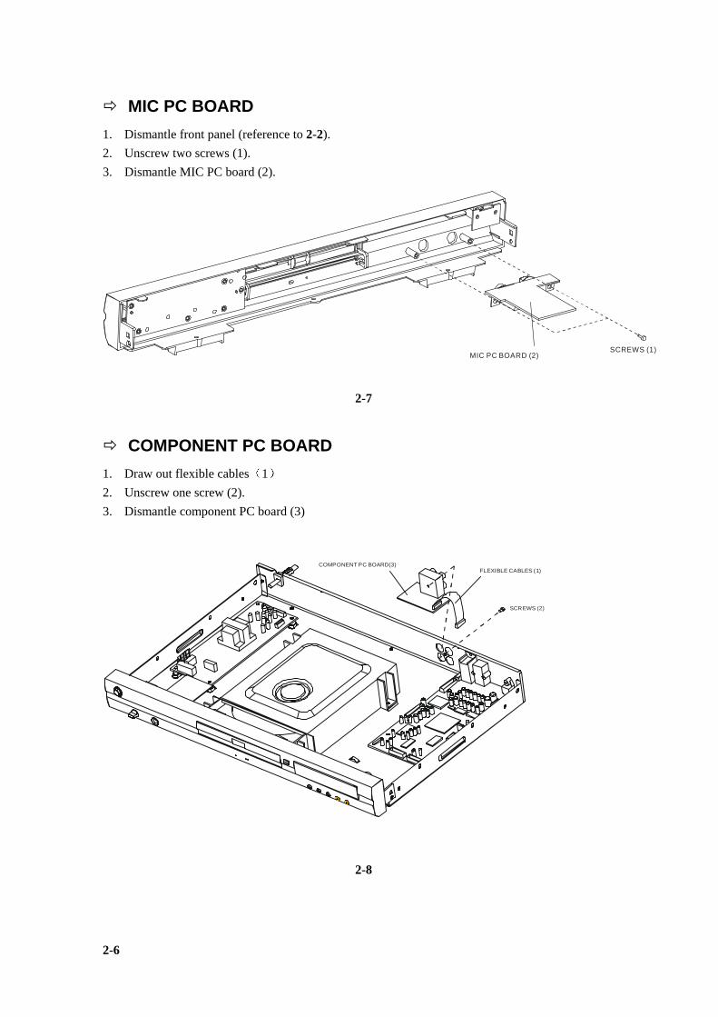
MIC PC BOARD 1. Dismantle front panel (reference to 2-2). 2. Unscrew two screws (1). 3. Dismantle MIC PC board (2).
SCREWS (1)MIC PC BOARD (2)
2-7
COMPONENT PC BOARD 1. Draw out flexible cables 1 2. Unscrew one screw (2). 3. Dismantle component PC board (3)
FLEXIBLE CABLES (1)
SCREWS (2)
COMPONENT PC BOARD(3)
2-8
2-6
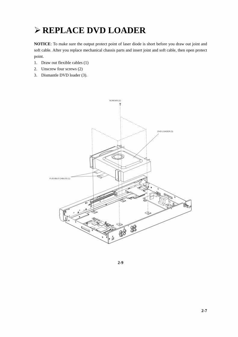
REPLACE DVD LOADER NOTICE: To make sure the output protect point of laser diode is short before you draw out joint and soft cable. After you replace mechanical chassis parts and insert joint and soft cable, then open protect point. 1. Draw out flexible cables (1) 2. Unscrew four screws (2) 3. Dismantle DVD loader (3).
FLEXIBLE CABLES (1)
SCREWS (2)
DVD LOADER (3)
2-9
2-7
DECODIN BLOCK D CONTRO POWER S MT1369A MT1336E MEMORY AUDIO AV FILTE KARAOK
3. OVERHAUL FLOWCHART
G BLOCK DIAGRAM ............................................................................ 3-2 IAGRAM ................................................................................................... 3-3 L SCHEMATIC CIRCUIT DIAGRAM .................................................. 3-4 CHEMATIC CIRCUIT DIAGRAM ....................................................... 3-5 E INDEX & POWER................................................................................. 3-6 SERVO MT1369AE MPEG DEMO BOARD.................................. 3-7 SCHEMATIC CIRCUIT DIAGRAM ................................................... 3-8 VIDEO DAC CIRCUIT DIAGRAM.................................................... 3-9
R SCHEMATIC CIRCUIT DIAGRAM................................................ 3-10 E SCHEMATIC CIRCUIT DIAGRAM.................................................3-11
3-1
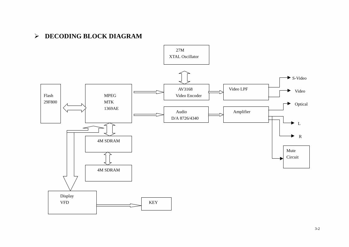
DECODING BLOCK DIAGRAM
27M XTAL Oscillator
S-Video Video Optical L R
Flash 29F800
4M SDRAM
4M SDRAM
Display VFD
MPEG MTK 1369AE
AV3168 Video Encoder
Video LPF
Mute Circuit
Amplifier Audio D/A 8726/4340
KEY
3-2
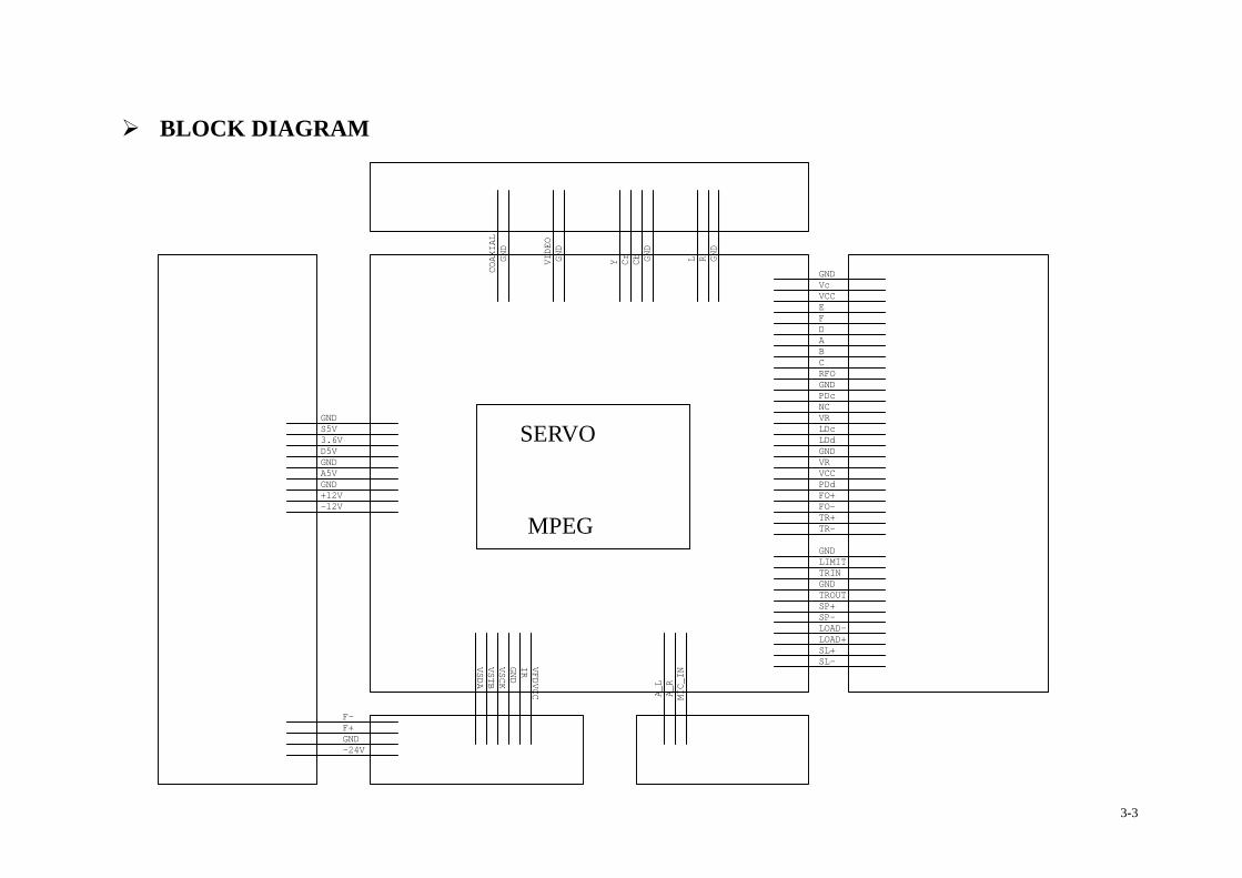
BLOCK DIAGRAM
GND
D5V
GNDA5V
LDd
COAXIAL
Cr
A
GND
LOAD-
VFDVCCL
LDc
SL-
GND VR
SP-
LIMIT
PDc
VSCK-24V
A_L
MIC_IN
B
FO+
GND
TRIN
GND
E
SP+
GNDF+
GND
GND
+12V
F-
PDd
VSTB
GND
VSDA
VRNC
C
-12V
TROUT
VCC
GND
LOAD+
Vc
VCC
GND
IR
TR+FO-
GND
CbYVIDEO
GND
TR-
D
R
S5V
F
3.6V
A_R
RFO
SL+
SERVO
﹠
MPEG
3-3
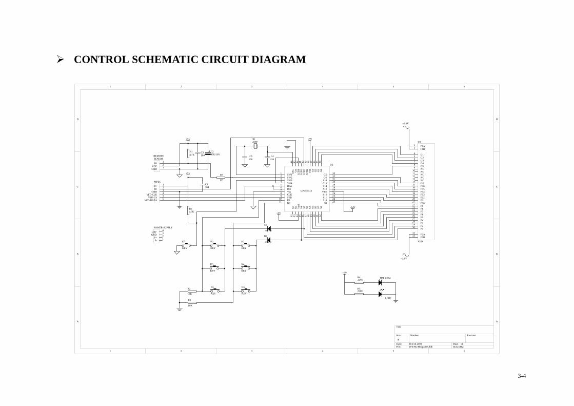
CONTROL SCHEMATIC CIRCUIT DIAGRAM
1 2 3 4 5 6
A
B
C
D
654321
D
C
B
A
Title
Number RevisionSize
B
Date: 18-Feb-2003 Sheet of File: D:\ENG\Bhdpa868.ddb Drawn By:
K2
KEY
K4
KEY
K1
KEY
K3
KEY
K6
KEY
K5
KEY
LED1
R14.7K
+5V
LED2
R5220E
R7
0E
C247U/16V
GND 1VCC 2IR 3
REMOTESENSOR
X1455E
C5150
C4150
F- 1F+ 2GND 3-24V 4POWER-SUPPLY
C3104
C1104
R4220E
R3
10K
R2
10K
D1
IN4148
D2
IN4148
+5V
~3.6V
~3.6V
VFD-DATA 6VFD-CS 5VFD-CLK 4GND 3IR 2+5V 1MPEG
P823
P724
P1219
P1120
P1021
P922
F1A1
F1B2
G14
G25
G36
G47
G58
NC9
NC10
NC11
NC12
NC13
G614
P1615
P1516
P1417
F2B33 F2A32
P130 P229 P328 P427 P526 P625
P1318
U1
VFD
Dout5
Din6
SW11
SW22
SW33
SW44 S15 30
S9 23
G5 33
G6 32
S16 31
Vss7
CLK8
STB9
K110
K211
S822
K3
12
K4
13
Vdd
14
S115
S216
S317
S418
S519
S620
S721
G4
34
OSC
44
Vss
43
LED
142
LED
241
LED
340
LED
439
Vdd
38
G1
37
G2
36
G3
35
S14 29
S10 24S11 25S12 26VEE 27S13 28
U2
UPD16312
+5V
+5V
-24V
+5V
K7
KEY
R64.7K
3-4
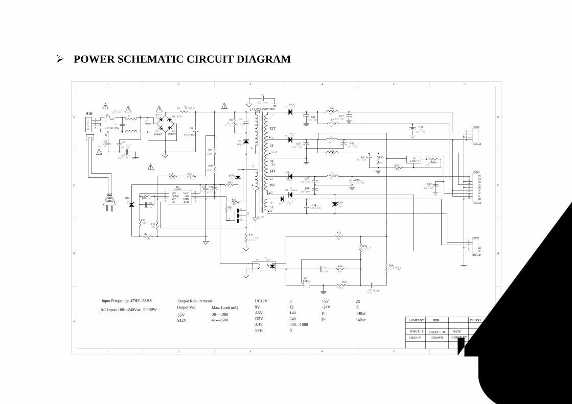
POWER SCHEMATIC CIRCUIT DIAGRAM
1 2 3 4 5 6
A
B
C
D
654321
D
C
B
A
1 3
2 4
T1
C1
C5C26
0.01u 1KV
D16
HER107
D15
IN4148
D7 HER302
D6 SR360
C30
0.22U(OPEN)
L3
10uH
F1T2AL 250V
! ! !
!
!
R11 82
R12
10
R1 NTC 100-11
R22
68K 1w
R32
47(0)
R29
150 R232.2K(OPEN)
D4D1
D3D2
D10 UF4004
!
C4222PF 400V
C2
222 400V
C3
222 400V
L
N
L2
10uH
9
6
1
3
1 2
1N4007 1N4007
1N40071N4007
18,15
16
17
T1 BYBYQDVD868
X'FMR
AC Input: 100---240Vac
Output Requirements :Input Frequency: 47HZ--63HZ
S5VS12V
Output Vol. Max. Load(mA)UC12V9VA5VD5V3.4VSTB
+5V-24VF-F+
20---120047---1500
312140240400---10005
253140ac140ac
Pt=30W
0.22UF 275V
GV-3802GVG
DESIGN
SHEET 1 OF 1
COMPANY
SHEET: 1 DATE
CHECK BYDRAWN APPROVED BY
C250.1u
C24
47UF 25V
C12220U/25V
C15220U/25V
C33
220u/25V
C9470U/10V
D1415V
C17470U/25V
C102200u/10V
D8
UF4004
C13470u/10V
14
12
13
10
D9 UF4004
R282.2 K(OPEN)
R264.7K 1%
C16100U/50V
C14100UF/10V
C11470U/25V
R27
220
R24
100K
C18
470U/10V
11
C8
47UF 400V
R17240K
R14
1.5M
R18
240K
R15
1.5M
56T
5T
12T
6T
5T
14T
26T
L
1 1
2 2
3 3
4 4
CON1
文件名称
版本号文件编号
INV1
COMP2 VCC 8
GD 7
GND 6VFF3
ZCD 5CS4
U2L6565
C23
0.22u
R19 12K
R20 10K R16
10K
R21
2.4K
R13
1.5 1/2W
1 S12V
2 GND
3 GND
4 S5V
CON2
CNS-4P
1 3
2
Q2
+12V2 -12V1
GND5
D5V6
3.6V7
S5V8
GND9
GND3
A5V4
CON4
CNS-9P
U6 PC817
C29
0.22U
D195V1
L1
10uH
L4
10uH
L7
10uH
R25
4.7K 1%
U5LM431
R10
47K
C6
1000P 250V
Q5LD1117
F-5
GND7
-24V8
F+2
CON5
RNS-4P
3-5
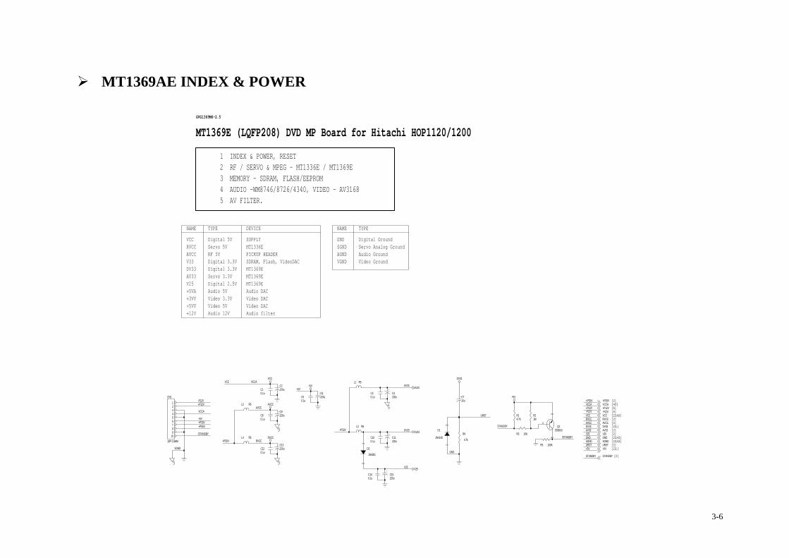
MT1369AE INDEX & POWER
Audio filter
DV33
VGND
SGND [ 2,3,4,5 ]
+5V
TYPEGND
AV33
GND
V25
V25
Video Ground
VCC
Servo 3.3V
C140.1u
+C11220u
MT1369E
2 RF / SERVO & MPEG - MT1336E / MT1369E
SGND
+5V
NAME
AV33/STANDBY
+C9220u
GVG1369M6-2.5
AV33
R14.7K
TYPE
+C15220u
Digital 5V
+C6220u
Audio DAC
VCCA
-P12VR21M
R3 10K
Video 5V
L1 FB
AVCC
+5V
+5V
SUPPLY
Digital 3.3VAGND
C30.1u
VCCA
MT1369E
V25
RVCC
-P12V
Digital 2.5V
Video 3.3V
+C710u
L2 FB
V25
+P12V
DV33
+P12V
SDRAM, Flash, VideoDAC
C120.1u
MT1336E
DV33L3 FB
VCC
+5VV
R4
4.7k
AV33
Servo Analog Ground
+C2220u
+C13220u
+12V
VCCA
Servo 5V
VCC
/STANDBY
+5VAVideo DAC
MT1369E (LQFP208) DVD MP Board for Hitachi HOP1120/1200
Audio 12V
+P33V
URST
1 INDEX & POWER, RESET
SGNDURST
GND
DV33
Video DAC
+PS5V
RF 5V
Audio 5V
Digital 3.3V
Audio Ground
RVCC
V33
+P12V [ 5 ]
5 AV FILTER.
AVCC
STANDBY
C80.1u
MT1369E
VCCA [ 4,5 ]
+5V [ 2,3, ]
DV33 [ 2,3, ]
+PS5V [ 2 ]
NAME
D1
1N4148
12
+3VV
-P12V [ 5 ]
V25 [ 2 ]
+PS5V
+C4220u
AVCC
AV33 [ 2 ]
D2
1N4001
12
3 MEMORY - SDRAM, FLASH/EEPROM
DEVICE
GND [ 2,3,4,5 ]
Digital Ground
RVCC
+PS5V
RVCC
STANDBY [ 2 ]
RVCC [ 2 ]
URST [ 2 ]
+P33V
C100.1u
DV33
C50.1u
4 AUDIO -WM8746/8726/4340, VIDEO - AV3168
AVCC [ 2 ]
VCC
L4 FB
VCC [ 2,3,4,5 ]
STANDBY
SGND
PICKUP HEADER
AVCC
CN1
10P 2.5MM
123456789
10
R5 100K+5V
C10.1u
Q1SS8550
1
23
3-6
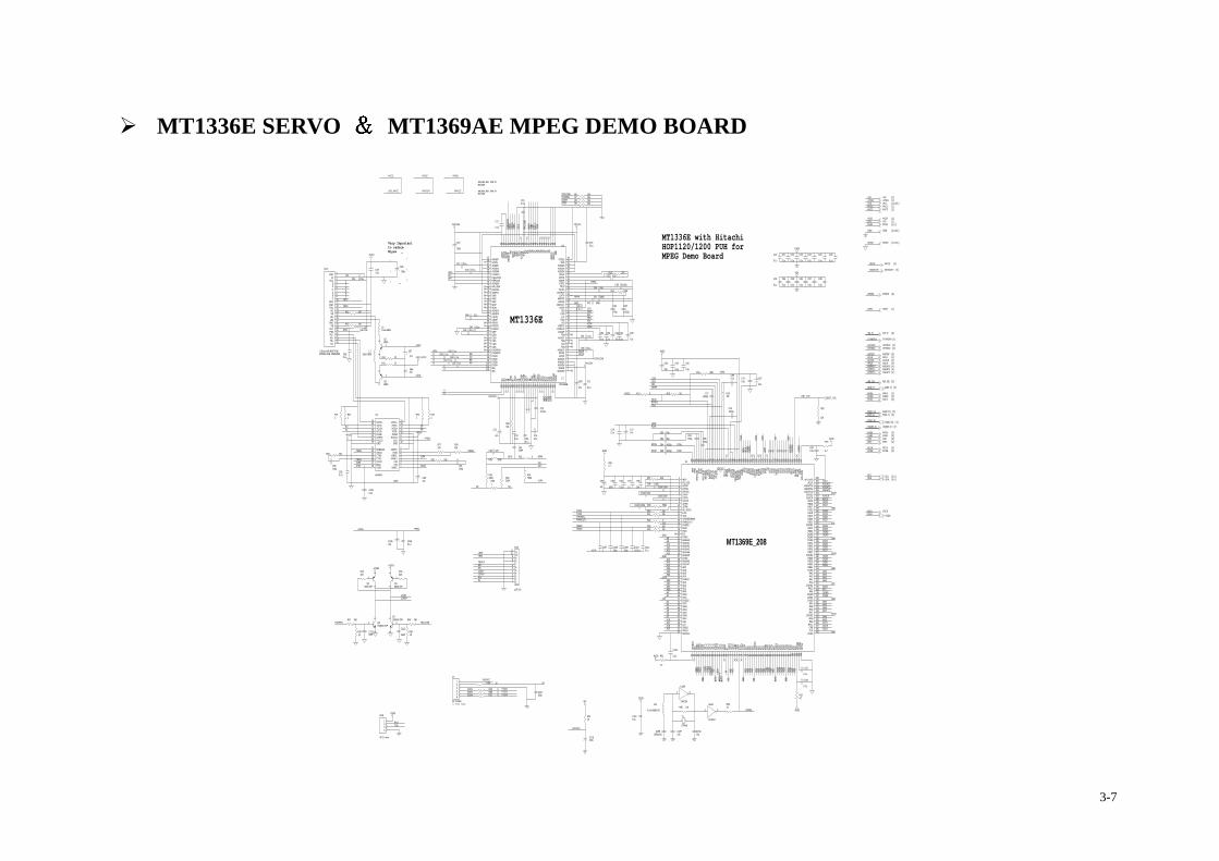
MT1336E SERVO MT1369AE MPEG DEMO BOARD
Y3
A3
RFL
L710uH 0805
Y7
TxD
SL-
+PS5V
Q58550 DIP
1
23
C115
0.1u
A
DQM3
LDO1
DQ5
DQ9
A7
GND
R7 10k
MT1336E
AVCC
A14
U18B
74HC04
3 4
RVCCIN
VFDVCC
A
A18
DQ20
C15422p
+C57
47u
R32 20K
A6
HTRC
STAN
DBY
C430.1u
C108330p
R9010
TROPEN
RVCC
FOSO
URST
SGND
C1110.1u
C112390P
Q6SS8050 DIP
1
23
GND
VCC
DV33
C91150p
GND
MA8
PCE#
SL+
R16 100k
A11
AV33
MA1
+C94
47u
CN4
11P 2.0
123456789
1011
1234567891011
DV33
STANDBY
LIMIT
IR
R47 390
R17 0
C760.1u
Very Importantto reduceNoise
LDO2
+PSM
C84 1000p
R54 10
R2533k
DQ15
AD1
PWR#
OPO
U18A
74HC04
1 2
R381
GND
MDI1
DQ28
ASDAT1
R37 8.2k
A19
RxD
AA
MUTE
C87 27P
GND
TRCLOSE
RFIN
GND
RVCCIN
TRSO
R221
R80 10k
MA11
SCL
DQ23
C700.1u
SDEN
CS#
DQ0
RxD
B
+ C118100u
C23
0.1u
RST_TVE
A13
V25
Y6
C44
470p
R20
10k
L510uH 0805
V-ST
B
GND
ABCK
E
TEO
MUTE [ 4 ]
CAS#
LOAD+
R15 22
MA7
OPO
BOTTOM SIDE CONTACTED ASPDIF [ 5 ]
R44 15k
RVCCIN
TROU
T
BDO
TROPEN
R39 750k
CN8
4P 2.0 mm
4321
PCE# [ 3 ]
HSYNC# [ 4 ]
V-SC
K
GND
DQ7
ALRCK
LDO1
C24
0.1u
AV33
C53
0.1u
R51
4.7
R34750K
C55 0.1u
C117100p
+PS5V
DV33
PRD#
C98
10n
C34
0.1u
C90150p
DQ11
SCL
C99 10n
A15
A0
DCKE
DQ27
RFVCC
R43 10k
C39 0.015u
R38,R49,R61: FOR 5VMT1336E
VSCK
A8
PWMOUT2
C26
0.1u
DQ2
DQ3
RFIPRFOP
V1P4
DQM[0..3] [ 3 ]
CS# [ 3 ]
A9
OP+
AD7
DQ19
SP--
C920.1u
RVCCIN
V25
DQ25
FMSO
C71
0.1u
+PS5V
VSDA
WE# [ 3 ]
SGND [ 1,3,4,5 ]
VSDA
WE#
TxD
C1060.1u
R29 20k
U3
BA5954
1
910
12
32
15
7
1413
21
1920
24
27
6
45
28
8
111718
16
2322
2526
29 30
VINFC
PVCC1PGND
VOSL+
CF2CF1
VOTK+
VNFFC
VOFC+VOFC-
PVCC2
PGNDVNFTK
CTK2
BIAS
VOSL
VINSL+VINSL-
STBY
VCC
VOSL-VOLD+VOLD-
VOTK-
VINLDPREGND
CTK1VINTK
GND GND
C102 10n
MA4
V1P4
V25
ASDAT0
FOSO
+ C50
10u
C86220P
BA[0..1] [ 3 ]
DV33 [ 1,3, ]
Y1
RFOP
RAS#
C114
0.1u
C113
390P
RAS# [ 3 ]
DQ[0..31] [ 3 ]
ADIN
DQM1
PCE#
DQM2
C890.1u
Y1
27MHz
C1581000p NC
AV33
AV33
+PS5V
A17
DQ1
AD4
E
R26
4.7
R46220
MA[0..11] [ 3 ]
VSYNC# [ 4 ]
MA2
Y2
+5V
C48 0.1u
R12 100
DV33
DCLK
MA10
ENDM
TRSO
C31 0.1u
C27 0.1u
RVCC [ 1 ]
SDAT
A
FEO
VSDA
C41 390p
AD3
ENDM
C95
100p
C780.1u
C22
0.1u
+ C28
100u
Y[0..7] [ 4 ]
AV33 [ 1 ]
DQ12
VSCK
R524.7
CSO
C107C
U4
MT1369E_208
53 54 55 56 57 58 59 60 61 62 63 64 65 66 67 68 69 70 71 72 73 74 75 76 77 78 79 80 81 82 83 84 85 86 87 88 89 90 91 92 93 94 95 96 97 98 99 100
101
102
103
104
208
207
206
205
204
203
202
201
200
199
198
197
196
195
194
193
192
191
190
189
188
187
186
185
184
183
182
181
180
179
178
177
176
175
174
173
172
171
170
169
168
167
166
165
164
163
162
161
160
159
158
157
156155154153152151150149148147146145144143142141140139138137136135134133132131130129128127126125124123122121120119118117116115114113112111110109108107106105
123456789
10111213141516171819202122232425262728293031323334353637383940414243444546474849505152
DMVD
D3AL
EIO
OE#
IOWR
#IO
CS#
DVSS
UP1_
2UP
1_3
UP1_
4UP
1_5
UP1_
6DV
DD3
UP1_
7UP
3_0
UP3_
1IN
T0#
IR DVDD
2UP
3_4
UP3_
5UW
R#UR
D#XT
ALI
XTAL
ODV
SSRD
7RD
6RD
5RD
4DV
DD2/3
RD3
RD2
RD1
RD0
RWE#
CAS#
RAS#
RCS#
BA0
DVDD
3RD
15RD
14RD
13RD
12DV
SSRD
11RD
10RD
9RD
8VP
VDD3
VCOC
INVP
VSS
RFIP
RFIN
RFDT
SLVN SC
OPSC
ONRF
DTSL
VPAD
CVDD
3HR
FZC
RFRP
SLV
RFRP
_AC
RFRP
_DC
RFLE
VEL FE
ICS
O TEI
TEZIS
LVRF
SUBI ADIN
ADCV
SSPD
MVSS
PWM2
VREF
PWMV
REF
PDMV
DD3
DVDD
3 BDO
SLCK
SDEN
SDAT
AW
OBSI
UDGA
TEDV
DD3
IFGAT
EVF
O13
DVSS
PRST IC
EYU
V7YU
V6YU
V5DV
DD2
YUV4
YUV3
YUV2
YUV1
YUV0
DVSS
HSYN
VSYN
BLAN
K#MC
_DAT
SPDI
FAP
LLVD
D3
APLLVSSACLK
ASDATA2ASDATA1ASDATA0
DVDD3ALRCK
ABCKRD16RD17DVSSRD18RD19RD20RD21
DVDD2RD22RD23DQM2DQM3DVSSRD24RD25RD26RD27
DVDD3RD28RD29RD30RD31DVSS
RA3RA2RA1RA0
DVDD2RA10
BA1DQM0DQM1DVSS
RA4RA5RA6RA7
DVDD3RA8RA9
RA11CKECLK
DVSS
IREFPLLVSSLPIOPLPIONLPFONLPFIPLPFINLPFOPJITFOJITFNPLLVDD3FOOTROTROPENPWNPWMOUT2DVDD2DMOFMOFGDVSSHIGHA0HIGHA1HIGHA2HIGHA3HIGHA4HIGHA5DVSSHIGHA6HIGHA7AD7AD6AD5AD4DVDD3AD3AD2AD1AD0IOA0IOA1DVDD2IOA2IOA3IOA4IOA5IOA6IOA7A16A17IOA18IOA19DMVSS
ACLK [ 4 ]
ACLK
AD5
Q48550 DIP
1
23
C36
0.1u
R57 0
R1918k
R46,R60,R63: FOR 3VMT1336E
AVCC [ 1 ]
V1P4
SDA
LOAD+
ABCK [ 4 ]
RST_TVE
+ C67
47u
C96
0.1u
URST [ 1 ]
GND
+ C68
47u
C82 20p
C61 1u
GND [ 1,3,4,5 ]
LIMIT
DQM[0..3]
C65
0.1u
C109330p
C560.1u
V25 [ 1 ]
PWR# [ 3 ]
A10
DQ31
ASDAT2
V1P4
R10 27k
R30 750K
DCKE [ 3 ]
MA0
HTRC
STBY
27MHZ
DV33
+PS5V
ALRCK [ 4 ]
ASDAT0 [ 4 ]
MA6
DV33
DQ18
D
FMSO
R48 390
C62 1u
V25
VSYN
C#
BB
DQ26
LDO2
C42 390p
+ C49
10u
27MHZ [ 4 ]
PRD# [ 3 ]
DCLK [ 3 ]
AD2
MICMUTE
SP+
R13 100
C1620.1u
AV33
VCC [ 1,3,4,5 ]
GND
OP+
V2P8
LOAD-
GND
V1P4
C1010.1u
A[0..19] [ 3 ]
Y[0..7]
V25
DDACLK
SP-
R11 100k
R334.7
R2710K
OP-
GND
+ C6647u
+5V
CAS# [ 3 ]
+PS5V [ 1 ]
HSYNC#
27MHZ
MA9
+PSM
C46 0.1u
C51 0.1u
C730.015u
DCKE
DQ13
Y0
C64
0.1u
V-SD
A
RVCC
RFRP
+5V [ 1 ]
DV33
TRCL
OSE
FEO
V-STB
RVCCIN
SCL [ 3,4 ]
V-SCK
C88 1000p
R45220
C30 0.1u MICMUTE [ 5 ]
ASDAT1 [ 4 ]
RFRPC
R8 10k
R241
WE#
A2
CSO
VSTB
Q7SS8050 DIP
1
23
V25
DV33
+PS5V
AD[0..7] [ 3 ]
DQ4
ASPDIF
DQ22
R231
V25
SDA [ 3,4 ]
CAS#
GND
SP+
TRIN
R5310
R55 0
PWMO
UT2
SDA
DMSO
RFON
C
SL+
C80 20p
STBY
SDEN
DQ6
BA0
V25
DQ29
ASDAT1
A
C160.1u
C104 100p
R2820k
V1P4
DQ17
C
STANDBY [ 1 ]
A[0..19]
SDAT
A
V25
MDI2
DQ24
R40 33k
C741000p
R42 0
B
MUTE
DV33
V20
C58 1u
ASDAT2 [ 4 ]
RFRP
MICM
UTE
SP--
V-SDA
BA1
RFZC
DQ14
STBY
SCLK
DQ8
L15
4.7uH 0805 NC
DQ[0..31]
AD0
ASDAT0
RFO
R491K
C810.1u
CS#
URST
R18 NC
DV33
PRD#
C85150p
C40 10p
C97
1u
TO FRONT PANEL
URST
VSYNC#
C190.1u
+ C18
100u
R41 33k
J7
6P 2.5MM
123456
RFL
VFDVCC
L6FB 1206
DV33
ASPD
IF
TROPEN
AVCC
C15722p
C116
0.1u
Y4 HSYN
C#
DMSO
TEO
C25
0.1u
C83150p
C32 27p
C52
0.1u
AD6
RAS#
DQM0
TRIN
CC
DQ21
V2P8
V20
MDI2
R56 0
+C75
47u
C59 1u
R31 0
R14 22
DQ10
+PS5V
SL-
R36330K
C1100.015u
+C9310u
C33
0.1u
C37
0.1u
C17
0.1u
F
Y5
RFONDCLK
A5
LDO_AVCC
ADIN
RFO
R211
CN2
0.5mm,24P,BOTTOM
123456789101112131415161718192021222324
GNDVc
VCCEFDABC
RFOGNDPDcNCVR
LDcLDd
GNDVR
VCCPDdFO+FO-TR+TR-
VSCK
IR
A16
DQ16
MDI1
C60 1u
C690.1u
MT1336E with Hitachi HOP1120/1200 PUH forMPEG Demo Board
RFVCC
C
SP-
C20
0.1u
Q38550
12
3
C38
0.1u
R501K
C100 10n
SCLK
C103 10n
C21
0.1u
D
AD[0..7]
LOAD-
Q28550
1
23
+ C63
47u
LDO_AVCC
TROUT
C35
0.1u
MA5
TRCLOSE
F
R6 10k
U2
MT1336E
128
127
126
125
124
123
122
121
120
119
118
117
116
115
114
113
112
111
110
109
108
107
106
105
104
103
3837363534333231302928272625242322212019181716151413121110987654321
3940414243444546474849505152535455565758596061626364
66676869707172737475767778798081828384858687888990919293949596979899
100101102
65
WGND
RFSU
BOLD
O2LD
O1MD
I1MD
I2AG
C3AG
C2W
AVDD
AGC1
WGAN
DSG
NDTN
ITP
ISV
DDCD
FON
CDFO
PSDSCAV
DDIRAG
NDSBSAMDMC
VFO13VDD
AGNDXAGNDXAGNDX
DPFODPFNGNDPHTRCTRLP
TRLPACRTPLP
CRTPHRFRPLRFRP
DEFECTVDDP
TEOCSOLVL
FEOV20
VREFOV2REFO
AVDDTTM4
AGNDTTM3TM2TM1
AGNDORFONRFOP
AVDDOAGNDXAGNDXWVDD
WOBSO
GND
UDGA
TEHD
GATEIO
0IO
1IO
2IO
3IO
4IO
5IO
6IO
7IO
8IO
9IO
AIO
BVD
DSXC
K16MSCLK
GNDS
SDEN
SDAT
ARST
DPDM
UTE
AGND
PAG
NDX
AVDD
P
VCONAVDDFAGNDXAVDDMCOSPHIHALLCOSREFCOSAGNDMHALLSINREFSINSINPHISW0SW2SW1MOPMONAGNDXAGNDXCEONCEOPRFGCIRFGCURFFGCOSPOSNCDDCDCCDBCDADVDRFINDVDRFIPDVDDDVDCDVDBDVDAMAMB
AGNDF
DV33
OP-
A12
ALRCK
A4
A1
AVCC
MA[0..11]
BDO
R35330K
ABCK
DQ30
ASDAT2
R9 10k
+C10510u
C721000p
B
PWR#
BA[0..1]
C290.1u
C54
0.1u
C47 0.1u
C790.1u
+ C7747u
GND
C45
0.033u
AV33
MA3
D
3-7
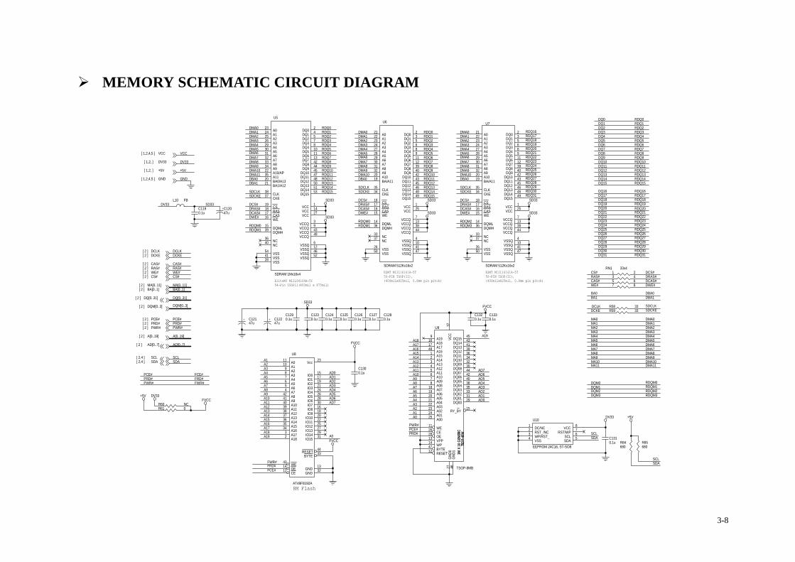
MEMORY SCHEMATIC CIRCUIT DIAGRAM
MA7
WE#
MA4
RDQ5
A7
DCS#
+ C12247u
MA0
A12
C1310.1u
(400milx825mil, 0.8mm pin pitch)
DQ14
RDQ24
PWR#
A11
RDQ15
MA8
RDQM1
RDQ30
SDCKE
DWE#
SD33
+ C12147u
DQM[0..3][ 2 ]
DMA11
RDQM0
DRAS#
MA[0..11][ 2 ]
DQ[0..31][ 2 ]
RDQ3
RDQ18
DMA1
50-PIN TSOP(II),
DMA10SDA
DWE#
DMA11
RDQ23DQ24
RDQ27
DMA1
A16DMA8
DMA4
A17
DMA3
A0
RDQ9
DCKE
L10 FB
MA1
RDQ2
RDQ10
AD6
DMA0
A[0..19]
CS#
DQ18
RDQ9
PCE#
SD33
RDQ4
RN1 33x41 23 45 67 8
ESMT M12L16161A-5T
DMA4
DQ23SD33
FVCC
DCLK[ 2 ]
DMA5
DMA0
DMA9
A4
DV33
CS#[ 2 ]
DQ11
RDQ29
SDCLK
RDQM1
RDQ24
R84680
R85680
A5
RDQ2
DQ2
DQ6DMA4
AD7
PWR#
PCE#[ 2 ]
DQM2
AD4
DMA5RDQ6
U8
AT49F8192A
1110987654
42414039383736353432
44
121443
33
15171921242628301618202225272931
23
1332
A0A1A2A3A4A5A6A7A8A9A10A11A12A13A14A15A16A17A18
RESET
CEOEWE
BYTE
IO0IO1IO2IO3IO4IO5IO6IO7IO8IO9
IO10IO11IO12IO13IO14IO15
Vcc
GNDGND
RAS#[ 2 ]
DQ8
DQ29
DCS#
SDCKE
DMA1
CS#
DQM1
R59 33
DMA5
RDQ12
RDQ6
DQ19
ESMT M12L16161A-5T
DCLK
RDQ7
DCAS#
RDQ17
RDQ3
PRD#
SD33
MA5
A14
DRAS#
RDQM3
DMA7
SDCLK
RDQ11
DBA0
DMA6
RAS#
DMA0
SDA
A13
DMA9
SDA[ 2,4 ]
DQ12
DMA0
54-Pin TSOPII(400mil x 875mil)
DCAS#
AD0
RDQ0
RDQ12
VCC[ 1,2,4,5 ]
RDQ14
DMA2
DQ17
GNDRDQ13
DQM3
C1190.1u
PCE#
A19
AD3
RDQ20
A5
DMA9
DCS#
DMA3
A13
DMA9
DMA4
EliteMT M12L64164A-5T
+5V[ 1,2, ]
RDQ3
TSOP
-48W
1M X
16 G
ENER
IC
U9
TSOP-8MB
3727 46
45434139363432304442403835333129
15
9161748
12345678
1819202122232425
12
11
47
26281314
VCC
GND0
GND1
DQ15DQ14DQ13DQ12DQ11DQ10DQ09DQ08DQ07DQ06DQ05DQ04DQ03DQ02DQ01DQ00
RY_BY
A19A18A17A16A15A14A13A12A11A10A09A08A07A06A05A04A03A02A01A00
RESET
WE
BYTE
CEOEVPPWP
RDQ13
RDQ1
FVCC
PWR#[ 2 ]
AD1
DRAS#
A3
DQ13
DQ20
RDQ30
DMA2
DMA6
SDA
C1260.1u
C1300.1u
RDQ14
DMA10
DMA6DMA5
RDQ11
SD33
DQM0
RDQ26
DBA0
A18
FWR#
A1
RDQ16
BA[0..1]
MA2
RDQ10
DQ3
RDQ27
DCS#
BA0
A12
FCE#
RDQ1
RDQ23
U10
EEPROM 24C16, ST-SO8
1234 5
678DC/NC
RST_/NCWP/RST_VSS SDA
SCLRST/WP
VCC
MA9
AD7
DQ30
A9
DMA7
RDQ8
PRD#
RDQ19
C1290.1u
R61 0
SD33
DV33[ 1,2, ]
A4
DCLK
DQ26
RDQ4
GND[ 1,2,4,5 ]
AD4
DMA3
RDQM3
RDQ6
DQ10
AD2
DQ27
RDQ25
SCL[ 2,4 ]
RDQ10
C1240.1u
+5V
DBA0
DQM[0..3]
AD5
R60 NC
SD33
A6
DWE#
DQ1
AD1
A[0..19][ 2 ]
RDQM0
RDQ15
RDQ21
A1
MA11
PRD#
DQ0
MA6
A6
CAS#
DBA0
FWR#
SCL
DMA8
RDQ29
SCL
+C12047u
C1280.1u
C1250.1u
RAS#
A16
RDQ28
SDCKE
RDQM0
DRAS#
+5V
RDQ12
DMA1
FRD#
RDQ0
RDQ17
PCE#
VCC
BA1
RDQ13
A2
AD2
DCKE[ 2 ]
RDQ9
FVCC
+5V
DCAS#
C1230.1u
8M Flash
DQ7
SDCLK
A0
DBA1
DQ28
RDQ22
RDQ22
RDQ2
CAS#[ 2 ]
DMA6
RDQM1
A10
RDQ16
MA[0..11]
DQ5
A11
DBA1
RDQ11
RDQ31
RDQ1
A17
U5
SDRAM 1Mx16x4
1
24
12
57
9
810
46
1113
15
16171819
3522
23242526
14
41
293031323334
36
3738
39
40
43
4244
52
4547
49
48505153
54
2021
3
6
27
28
VCC
DQ0DQ1
VSSQ
DQ2DQ3
VCCQ
DQ4DQ5
VSSQ
DQ6DQ7
DQML
WECASRASCS
A11A10/AP
A0A1A2A3
VCC
VSS
A4A5A6A7A8A9
NC
CKECLK
DQMH
NC
VCCQ
DQ8DQ9
VSSQ
DQ10DQ11
VCCQ
DQ12DQ13DQ14DQ15
VSS
BA0/A13BA1/A12
VCCQ
VSSQ
VCC
VSS
RDQ8
SDCLK
DQ9
A7
DQ[0..31]
WE#
DMA10
DQ22
DCAS#
A15
U6
SDRAM 512Kx16x2
1
23
4
56
7
89
10
1112
1314
15161718
1920
21222324
25
26
272829303132
33
3435
36
37
38
3940
41
4243
44
4546
47
4849
50
VCC
DQ0DQ1
VSSQ
DQ2DQ3
VCCQ
DQ4DQ5
VSSQ
DQ6DQ7
VCCQDQML
WECASRASCS
BA/A11A10
A0A1A2A3
VCC
VSS
A4A5A6A7A8A9
NC
CKECLK
DQMH
NC
VCCQ
DQ8DQ9
VSSQ
DQ10DQ11
VCCQ
DQ12DQ13
VSSQ
DQ14DQ15
VSS
DV33
RDQ25
DQ16
RDQ0
RDQ18
MA10
RDQ5
DQ31
DMA7
BA[0..1][ 2 ]
A2
DMA10
RDQ31
PRD#[ 2 ]
RDQ7
A3
DV33
RDQ28
R58 33
DV33
DMA3
DQ25
DWE#
AD0
AD[0..7]
A15
RDQ15
DMA2
A8
FCE#
U7
SDRAM 512Kx16x2
1
23
4
56
7
89
10
1112
1314
15161718
1920
21222324
25
26
272829303132
33
3435
36
37
38
3940
41
4243
44
4546
47
4849
50
VCC
DQ0DQ1
VSSQ
DQ2DQ3
VCCQ
DQ4DQ5
VSSQ
DQ6DQ7
VCCQDQML
WECASRASCS
BA/A11A10
A0A1A2A3
VCC
VSS
A4A5A6A7A8A9
NC
CKECLK
DQMH
NC
VCCQ
DQ8DQ9
VSSQ
DQ10DQ11
VCCQ
DQ12DQ13
VSSQ
DQ14DQ15
VSS
RDQ8 DMA8
C1330.1u
(400milx825mil, 0.8mm pin pitch) CAS#
DMA8
DCKE
SD33
DMA7
RDQ4
RDQM2
RDQ21
MA3
RDQ7
RDQ20
SCL
A19
AD[0..7][ 2 ]
AD6
PWR#
DMA2
A18
A8AD5
RDQ26
A9
C1270.1u
FRD#
AD3
RDQ19
A10
50-PIN TSOP(II),
FVCC
C1320.1u
WE#[ 2 ]
DQ4
DQ15
DQ21
A14
SDCKE
RDQ5
RDQ14
RDQM2
3-8
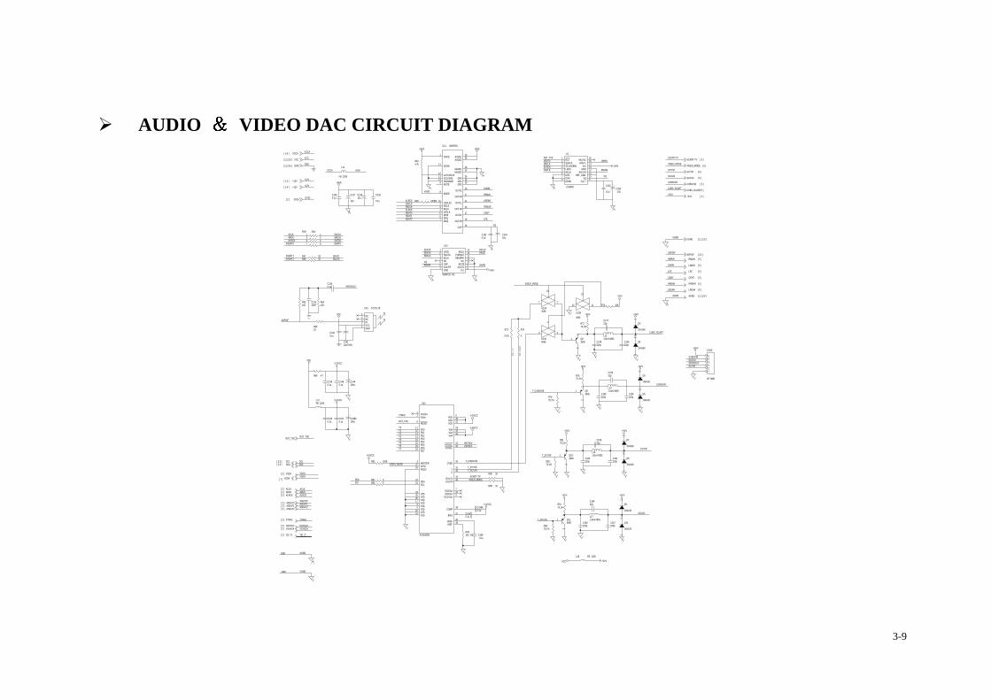
AUDIO VIDEO DAC CIRCUIT DIAGRAM SCART-TV [ 5 ]
CENT
ABCK
R68 33
+5VA
ACLK
GND
VCCA[ 1,4 ]
RREAR [ 5 ]
L13FB 1206
SY/Y/R [ 5 ]
T_CVBS/V/B
R7275,1%
CP1 TOTX178
12345
GNDVCCINNCNC
VSDA[ 2 ]
VSCK
R9275,1%
C1340.1u
DV33[ 2 ]
CENTSLRCK
LMAIN
U1
CS4340
12345678
161514131211109
RSTSDATASCLK/DEM1LRCKMCLKDIF1DIF0DEM0
MUTECAOUTL
VccGND
AOUTRREF_GND
VQFILT+
+5VV
+12V[ 1,4 ]
C155220p
U11 WM8746
1
11
1213149
8
10234567
1528
2024
262218
27
25
23
21
19
17
16
DVDD
DGND
LATCH/12SSCLK/IWLSDIN/DM0MUTE
MODE
LRCLK2MCLKBCLKLRCLKDIN0DIN1DIN2
AVDD1AVDD2
AGND1AGND2
GR0GR1GR2
OUT0R
OUT0L
OUT1R
OUT1L
OUT2R
OUT2L
CAP
R69 4.7
VIDEO_MODE [ 5 ]
SACLK
SCART-TV
C1420.1u
ABCK
R624.7k
ASDAT0
R7975,1%
FOR YU
V
V-AVCC
SPDIFOUT
Q103906
1
23
CENT [ 5 ]
SDAT1
+5VA
LMAIN
SY/Y/R
R88 1K
HSYNC#
Y1
+5VA
+5VV
C135330P
ASDAT1[ 2 ] ASDAT1
Q113906
1
23
C152
0.1u
C149220p
VSDA
Y5
CVBS_SCART[ 5 ]
SC/U/G
C1500.1u
C148220p
U14
AV3168/69
2
6
1112131415161819
2324
10
293236
2120
35
3133
39
8172630
40
1
22
5
34
4142
4
32728
38
37
9257
4443
XckIn
RESET
PD0PD1PD2PD3PD4PD5PD6PD7
SDASCL
VDD
VAAVAAVAA
HSYNCVSYNC
CVBS
YC
IREF
VSSVSSVSSVSS
VREF
XckOut
VDD
VDD
VSS
VSSVSSVSS
MASTERCPNTPDEN
COMP
BIAS
CK27OutACKOutGCKOut
GOUT1GOUT0
+5VV
LFE
RMAIN
C1400.1u
ASPDIF
SACLK
R8375,1%
+5VV
VCC
VIDEO_MODE
Q83906
1
23
ASDAT2[ 2 ]
SY/Y/R
SCL
VGND
+12V[ 1,4 ]
D10
1N4148
12
SDAT0
R7675,1%
VSYNC#
T_SC/U/G
C16422p
R67 33
C139
0.1u
ACLK[ 2 ]
VCCA
CVBS_SCART
L161.8uH 0805
C1450.1u
U13B4066
1110
12
RMAIN
SDAT0
CVBS_SCART
C167220p
VCC
Y[0..7]
C156220p
ASDAT2
SDAT0
V-AVCC
LFE [ 5 ]
SBCLK
D8
1N4148
12T_SY/Y/R
R82 100E
D4
1N4148
12
+5VV
+12V
CVBS/V/B
U12
WM8726 NC
4
23
1 14
7
1098
13
6
1112
5 NC
SDATABCLK
LRCK MCLK
GND
MUTEAOUTL
Vcc
FORMAT
AOUTR
NCDEEMPH
CAP
C1510.1u
+5VV
VCC
SDAT2
VCC
T_SC/U/G
CN10
6P 2MM
123456
D5
1N4148
12
SACLK
R64100
U13C4066
4 3
5
R86 1K
ALRCK[ 2 ]
RST_TVE
+C1989100u
ASPDIF
C19880.1u
+5VV
T_CVBS/V/B
Y0
D9
1N4148
12
+5VV
VIDEO_MODE
HSYNC#
ABCK[ 2 ]
AGND
R65 OPEN
R74
0
C14310u
L18 FB 1206
VQ
ASDAT0
R73
0 NC
R89 0
+5VA
LREAR
VGND [ 1,2,3,5 ]
C161220p
GND[ 1,2,3,5 ]
RMAIN
C15322p
+5VV [ 5 ]
SC/U/G
Y2
GND
Y[0..7][ 2 ]
VAUD
D3
1N4148
12
SDAT2
VAUDSLRCK
CVBS/V/B
LMAIN+12V
D6
1N4148
12
CVBS/V/B [ 5 ]
ASDAT1
RN2 33x41 23 45 67 8
VCC[ 1,2,3,5 ]
27MHZ
Y4
L141.8uH 0805
VQ
SCL[ 2,3 ]
SBCLK
ALRCK
R63100
C1650.1u
ASPDIF [ 2,5 ]
VCCA
Y7
C1360.1u
LREAR
SLRCK
R6633
SPDIFOUT
HSYNC#[ 2 ]
LMAIN
Q93906
1
23
RST_TVE
SCL
RST_TVE
R87 0
C15922p
VSCK[ 2 ]
RREAR
R8175,1%
L171.8uH 0805
V-DVCC
V-DVCC
L11
FB 1206
C14110uF/16V
+5VA
ALRCK
VIDEO_MODE
VIDEO_MODESDA
+5VV
LREAR [ 5 ]
SDAT1
VSYNC#
GND
+5VA
RMAIN
C137
10u
+5VV
LFE
+C144100u
LMAIN [ 5 ]
SC/U/G [ 5 ]
C166220p
D7
1N4148
12
C1680.1u
RMAIN [ 5 ]
SLRCK
R9175,1%
V-AVCC
27MHZ
L121.8uH 0805
VQ
SDAT0
SY/Y/R
+5VV
ALRCK
CVBS/V/B
C160220p
V-DVCC
RREAR
RST_TVE
C1460.1u
U13A4066
1 2
13
FOR SC
ART
DV33
+C16310u
AGND [ 1,2,3,5 ]
SBCLK
ACLK
C13810u
SDA[ 2,3 ]
27MHZ[ 2 ]
AGND
VSYNC#[ 2 ]
SC/U/G
R93330, 1%
SBCLK
C14722p
VGND
+5VV
ASDAT0[ 2 ]
SDA
Y6
R70 10K
SACLK
SCART-TV
T_SY/Y/R
Y3
ASDAT2
3-9

AV FILTER SCHEMATIC CIRCUIT DIAGRAM
A-LR
D13 1N4148
1 2
A-RR
L23
FB 1206
L25
FB 1206
C179
1000p
C196
150p
+5VA
CVBS/V/B
R127470
R96 10k C173
1000p
SSOP8
C2121000P
R121 2.2k
C211
1000p
R144 100K
SY/Y/R
R113 1K
-P12V
+
C18810u
R98470
SSOP8
CVBS_SCART-12V
CP3
AV3X2
1
2
6
4
8
9
3
7
5
1
2
6
4
8
9
3
7
5
R13218k
VIDEO_MODE
RREAR
C195
0.1u
+12V
AGND
A_MUTE
-12V
+
C17810u
+
- U16A
NJM45803
21
84
R136
4.7K
L19
FB 1206
+12V
MICIN
R119 1K
R10818k
SSOP8
A-C
R111470
H1CIRDIN_9-R
1
2
3
4 5 6
7
8
9
D121N4148
12
-P12V
+12V
L27 FB 1206
R97 3.3k
R145 100K
R143 1K
A_MUTE
+C182
220u
R1103.3k
C186
150p
+
C169
10u
-12V
CVBS_SCART
SSOP8
A-L
C2131000pF
Q193904
2
1
3
R118100K
-12V
A-R
R112100K
RREAR
C1741000P
R101 10k
GND
A-L
-12V
MIC_IN
+P12V
CN12
4P 2.5MM1234
+P12V
CENT
-12V
A-R
+C175
10u
R131 470K
R130 NC
SSOP8
R99100K
C185
0.1u
C2071000P
Q153904
2
1
3
VGND
R105470
L41 FB 1206
D11 1N41481 2
Q17SS8550
1
23
L20
FB 1206
A-RR
R11418k
R1243.3k
MUTE
R139 470
R9518k
+
C187
10u
A-L
SC/U/G
+12V
C170
150p
+12V
R129 1K
L26
FB 1206
MICIN
C176
150p
SY/Y/R
A_MUTE
SSOP8
VCCA
+
C21010u
R142 10K
+C209
10u
CVBS_SCART
R94 10k
R106100K
+5VV[ 4 ]
+
- U15A
NJM45803
21
84
+12VCP2 S-video
2
1
54
6 7
3
891011
L40 FB 1206
R123 10k
C1801000P
Q123904
2
1
3
Q213904
2
1
3
SC/U/G
+
C19810u
R128100K
MUTE
A-R
R1163.3k
C181
0.1u
C183
0.1u
AGND[ 1,2,3,4 ]
LREAR
A-C
R103 10kMUTE[ 2 ]
+P12V[ 1 ]
MICMUTE
MIC_IN
R137
1M
R109 10k
+
- U17A
NJM45803
21
84
A_MUTE
+
C202220U/25
RMAIN
+
C171
10u
A_MUTE
+12V
LMAIN[ 4 ]
VIDEO_MODE[ 4 ]VIDEO_MODE
R138470
MICMUTE[ 2 ]
R1353.3k
C208
150p
-P12V[ 1 ]
LMAIN
+5VV
VGND[ 1,2,3,4 ]
A_MUTE
L22
FB 1206
+C192
220u
RMAIN[ 4 ]
SC/U/G
+
C20510u
R134 10k
LREAR[ 4 ]
A-LFE
CENT[ 4 ]
LFE
L21 FB 1206
C206
1000p
Q133904
2
1
3
CVBS/V/B[ 4 ]
SCART-TV[ 4 ]
+C197
10u
R117470
+12V[ 4 ]
MICIN
CENT
L29 FB 1206
+
C17210u
C194
0.1u
SC/U/G[ 4 ]
C193
0.1u
C2001000P
-12V
CVBS_SCART[ 4 ]
+12V
R1043.3k
H2CIRDIN_9-R
1
2
3
4 5 6
7
8
9
R107 1K
-12V
+12V
C1901000P
+
C177
10u
RREAR[ 4 ]
C189
1000p
C2141000pF
GND[ 1,2,3,5 ]
LFE[ 4 ]
A-L SCART-TV
+C240220U
Q16SS8550
1
23
RMAIN
C199
1000p
R12610K
Q143904
2
1
3
A_MUTE
+
C204
10u
+12V
SY/Y/R
R12218k
R10218k
+
- U16B
NJM45805
67
84
+
- U15B
NJM45805
67
84
+
- U17B
NJM45805
67
84
SY/Y/R[ 4 ]
VCCA[ 1,4 ]
R1206.8k
L28 FB 1206
R141 1K
+5VA
A-LR
A-R
+P12V
-12V
Q203906
1
23
+C201470U
SCART-TV
LFE
CN11
13P 2MM
123456789
10111213
12345678910111213
Q183904
2
1
3
CVBS/V/B
A-LFE
R100 1K
LREAR
+5VV
C184
0.1u
MICMUTE
VIDEO_MODE 0V CVBS MODE 5V RGB MODE
C191
0.1u
R140100K
R115 10k
LMAIN
L24
FB 1206
C203
150p
3-10
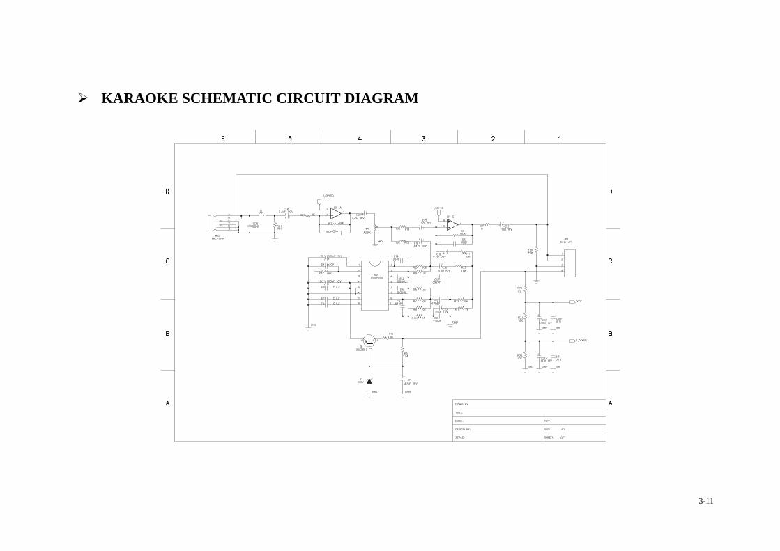
KARAOKE SCHEMATIC CIRCUIT DIAGRAM
3-11
MT1369E IC MATERIAL ..
DECAL ....................... PIN FUNCTION DESC
CS4340(AUDIO D/A) IC M DECAL ....................... PIN FUNCTION DESC
AV 3168 VIDEO IC MA DECAL ....................... PIN FUNCTION DESC
FLASH 29F800 IC MATER DECAL ....................... PIN FUNCTION DESC
CONTROL PANEL IC MAT DECAL ....................... PIN FUNCTION DESC
16M SDRAM IC MATERIA DECAL ....................... PIN FUNCTION DESC
4. IC MATERIAL
.................................................................................................. 4-2
.................................................................................................. 4-2 RIPTION ................................................................................ 4-3
ATERIAL ................................................................................ 4-8 .................................................................................................. 4-8 RIPTION ................................................................................ 4-8
TERIAL................................................................................... 4-9 .................................................................................................. 4-9 RIPTION .............................................................................. 4-10
IAL......................................................................................... 4-12 ................................................................................................ 4-12 RIPTION .............................................................................. 4-12 ERIAL .................................................................................. 4-13
................................................................................................ 4-13 RIPTION .............................................................................. 4-13 L............................................................................................ 4-14
................................................................................................ 4-14 RIPTION .............................................................................. 4-15
4-1
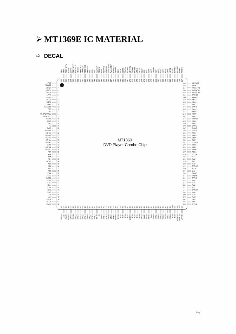
MT1369E IC MATERIAL
DECAL
MT1369DVD Player Combo Chip
111
RA4
110109
107106105
108
RA7RA6RA5
VPVS
S
150149
147146145
148
143142141
144
139138137
140
135134133
136
131130129
132
127126125
128
123122121
124
119118117
120
115114113
116
112
RD26
DQM1
RA0
DQM0BA1
RD30
RA10
RA1RA2RA3
RD31
DVDD2
RD29RD28
RD27DVDD3
RD21
RD25RD24
DQM2
RD22RD23
DQM3
RD18RD19RD20
RD17
DVDD2
ABCKRD16
ASDATA2ASDATA1
DVSS
ALRCK
ASDATA0
155154153
156
151152
78
101112
9
141516
13
181920
17
222324
21
262728
25
303132
29
343536
33
383940
37
424344
41
4645
DVSS
IOA1IOA0
IOA3IOA4
IOA2
DMO
DVSS
DVDD2
FMOFG
TROFOO
LPFIN
PLLVDD3JITFNJITFO
LPFOP
PLLVSS
4748
505152
49
IOA5IOA6IOA7
IPVSS
234
1
65
IREF
LPIONLPIOP
LPFIPLPFON
RFR
P_AC
163
164
165
166
167
168
169
170
171
172
173
174
175
176
177
178
179
180
181
182
183
184
185
186
187
188
189
190
191
192
193
194
195
196
197
198
199
200
201
202
YUV5
YUV6
YUV7
RFR
PSLV
RFR
P_DC
FEI
RFL
EVEL
HR
FZC
ADC
VDD
3
PRST
VFO
13
DVD
D3
DVS
S
IDG
ATE
SDAT
A
DVD
D3
CSO
PWM
VREF
BDO
UD
GAT
E
SDEN
WO
BSI
SLC
K
TEI
PDM
VDD
3
PWM
2VR
EFPD
MVS
SAD
CVS
SAD
INR
FSU
BITE
ZISL
V
DVD
D2
157
158
159
160
161
162
APVDD3
YUV4
YUV2
VCO
CIN
APVS
S
YUV3
SCO
P
203
204
205
206
207
208
RFI
NR
FDTS
LVN
RFI
P
RFD
TSLV
PSC
ON
98979695949392919089888786858483828180797877767574737271706968676665646362616059
DVDD
3
UP3
_5
IOO
E#
INT0
#
UP1
_7
XTAL
O
UP3
_4
XTAL
I
UP3
_0
RD5
DVS
S
RD4
RD6
RD3
RD2
RD1
RD0
RWE#
CAS
#R
AS#
RC
S#
RD14
RD13
RD12
BA0
RD15
RD10
RD9
RD11
RD7
DVDD
3
585756555453IP
VDD3
104
103
102
101
100
99
VPVD
D3
CLK
DVS
S
CKE
DVDD3
DVSS
ACLK
SPD
IFM
C_D
AT
DVS
S
DVDD2
DVS
S
YUV1
YUV0
HSY
NVS
YNBL
ANK#
DVSS
DVDD2RA8RA9
DVSS
RA11
DVDD
2
DVDD
2
IOC
S#
AD3
AD1AD0
AD2
HIGHA0
HIGHA3
HIGHA1HIGHA2
HIGHA5
AD6AD5
AD7
AD4
HIGHA4
HIGHA6HIGHA7
A16A17
IOA18
IOW
R#
UP1
_2U
P1_3
UP1
_4U
P1_5
UP1
_6
ICE
UP3
_1
URD
#IR
UW
R#
ALE
DVDD3
TROPENPWMPWMOUT2
IOA19
RD8
DVSS
4-2
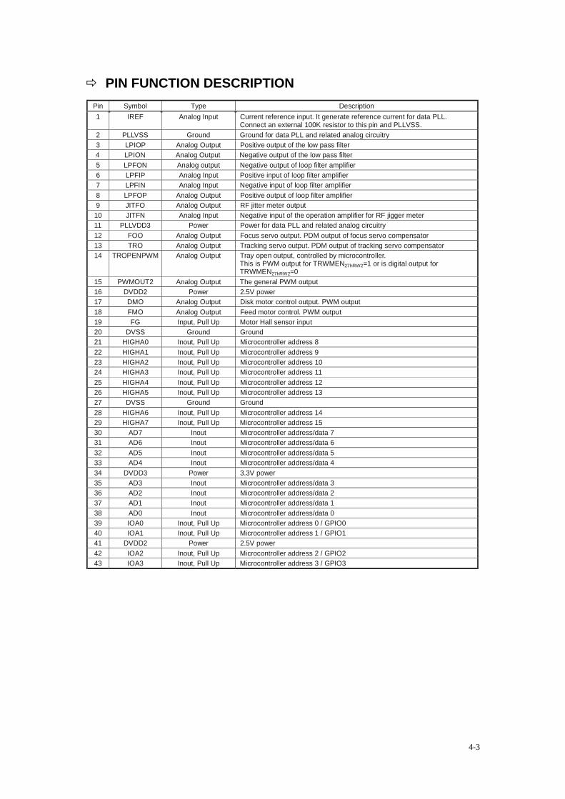
PIN FUNCTION DESCRIPTION Pin Symbol Type Description 1 IREF Analog Input Current reference input. It generate reference current for data PLL.
Connect an external 100K resistor to this pin and PLLVSS. 2 PLLVSS Ground Ground for data PLL and related analog circuitry 3 LPIOP Analog Output Positive output of the low pass filter 4 LPION Analog Output Negative output of the low pass filter 5 LPFON Analog output Negative output of loop filter amplifier 6 LPFIP Analog Input Positive input of loop filter amplifier 7 LPFIN Analog Input Negative input of loop filter amplifier 8 LPFOP Analog Output Positive output of loop filter amplifier 9 JITFO Analog Output RF jitter meter output
10 JITFN Analog Input Negative input of the operation amplifier for RF jigger meter 11 PLLVDD3 Power Power for data PLL and related analog circuitry 12 FOO Analog Output Focus servo output. PDM output of focus servo compensator 13 TRO Analog Output Tracking servo output. PDM output of tracking servo compensator 14 TROPENPWM Analog Output Tray open output, controlled by microcontroller.
This is PWM output for TRWMEN27hRW2=1 or is digital output for TRWMEN27hRW2=0
15 PWMOUT2 Analog Output The general PWM output 16 DVDD2 Power 2.5V power 17 DMO Analog Output Disk motor control output. PWM output 18 FMO Analog Output Feed motor control. PWM output 19 FG Input, Pull Up Motor Hall sensor input 20 DVSS Ground Ground 21 HIGHA0 Inout, Pull Up Microcontroller address 8 22 HIGHA1 Inout, Pull Up Microcontroller address 9 23 HIGHA2 Inout, Pull Up Microcontroller address 10 24 HIGHA3 Inout, Pull Up Microcontroller address 11 25 HIGHA4 Inout, Pull Up Microcontroller address 12 26 HIGHA5 Inout, Pull Up Microcontroller address 13 27 DVSS Ground Ground 28 HIGHA6 Inout, Pull Up Microcontroller address 14 29 HIGHA7 Inout, Pull Up Microcontroller address 15 30 AD7 Inout Microcontroller address/data 7 31 AD6 Inout Microcontroller address/data 6 32 AD5 Inout Microcontroller address/data 5 33 AD4 Inout Microcontroller address/data 4 34 DVDD3 Power 3.3V power 35 AD3 Inout Microcontroller address/data 3 36 AD2 Inout Microcontroller address/data 2 37 AD1 Inout Microcontroller address/data 1 38 AD0 Inout Microcontroller address/data 0 39 IOA0 Inout, Pull Up Microcontroller address 0 / GPIO0 40 IOA1 Inout, Pull Up Microcontroller address 1 / GPIO1 41 DVDD2 Power 2.5V power 42 IOA2 Inout, Pull Up Microcontroller address 2 / GPIO2 43 IOA3 Inout, Pull Up Microcontroller address 3 / GPIO3
4-3
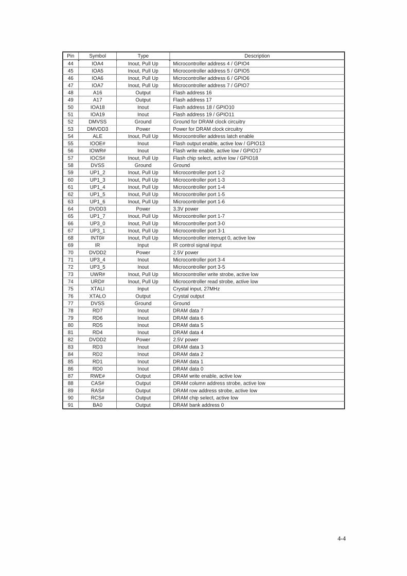
Pin Symbol Type Description 44 IOA4 Inout, Pull Up Microcontroller address 4 / GPIO4 45 IOA5 Inout, Pull Up Microcontroller address 5 / GPIO5 46 IOA6 Inout, Pull Up Microcontroller address 6 / GPIO6 47 IOA7 Inout, Pull Up Microcontroller address 7 / GPIO7 48 A16 Output Flash address 16 49 A17 Output Flash address 17 50 IOA18 Inout Flash address 18 / GPIO10 51 IOA19 Inout Flash address 19 / GPIO11 52 DMVSS Ground Ground for DRAM clock circuitry 53 DMVDD3 Power Power for DRAM clock circuitry 54 ALE Inout, Pull Up Microcontroller address latch enable 55 IOOE# Inout Flash output enable, active low / GPIO13 56 IOWR# Inout Flash write enable, active low / GPIO17 57 IOCS# Inout, Pull Up Flash chip select, active low / GPIO18 58 DVSS Ground Ground 59 UP1_2 Inout, Pull Up Microcontroller port 1-2 60 UP1_3 Inout, Pull Up Microcontroller port 1-3 61 UP1_4 Inout, Pull Up Microcontroller port 1-4 62 UP1_5 Inout, Pull Up Microcontroller port 1-5 63 UP1_6 Inout, Pull Up Microcontroller port 1-6 64 DVDD3 Power 3.3V power 65 UP1_7 Inout, Pull Up Microcontroller port 1-7 66 UP3_0 Inout, Pull Up Microcontroller port 3-0 67 UP3_1 Inout, Pull Up Microcontroller port 3-1 68 INT0# Inout, Pull Up Microcontroller interrupt 0, active low 69 IR Input IR control signal input 70 DVDD2 Power 2.5V power 71 UP3_4 Inout Microcontroller port 3-4 72 UP3_5 Inout Microcontroller port 3-5 73 UWR# Inout, Pull Up Microcontroller write strobe, active low 74 URD# Inout, Pull Up Microcontroller read strobe, active low 75 XTALI Input Crystal input, 27MHz 76 XTALO Output Crystal output 77 DVSS Ground Ground 78 RD7 Inout DRAM data 7 79 RD6 Inout DRAM data 6 80 RD5 Inout DRAM data 5 81 RD4 Inout DRAM data 4 82 DVDD2 Power 2.5V power 83 RD3 Inout DRAM data 3 84 RD2 Inout DRAM data 2 85 RD1 Inout DRAM data 1 86 RD0 Inout DRAM data 0 87 RWE# Output DRAM write enable, active low 88 CAS# Output DRAM column address strobe, active low 89 RAS# Output DRAM row address strobe, active low 90 RCS# Output DRAM chip select, active low 91 BA0 Output DRAM bank address 0
4-4
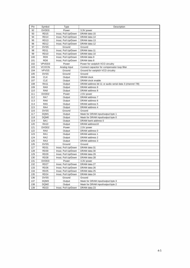
Pin Symbol Type Description 92 DVDD3 Power 3.3V power 93 RD15 Inout, Pull Up/Down DRAM data 15 94 RD14 Inout, Pull Up/Down DRAM data 14 95 RD13 Inout, Pull Up/Down DRAM data 13 96 RD12 Inout, Pull Up/Down DRAM data 12 97 DVSS Ground Ground 98 RD11 Inout, Pull Up/Down DRAM data 11 99 RD10 Inout, Pull Up/Down DRAM data 10
100 RD9 Inout, Pull Up/Down DRAM data 9 101 RD8 Inout, Pull Up/Down DRAM data 8 102 VPVDD3 Power Power for varipitch VCO circuitry 103 VCOCIN Analog Input Connect capacitor for compensator loop filter 104 VPVSS Ground Ground for varipitch VCO circuitry 105 DVSS Ground Ground 106 CLK Output DRAM clock 107 CLE Output DRAM clock enable 108 RA11 Output DRAM address bit 11 or audio serial data 3 (channel 7/8) 109 RA9 Output DRAM address 9 110 RA8 Output DRAM address 8 111 DVDD2 Power 2.5V power 112 RA7 Output DRAM address 7 113 RA6 Output DRAM address 6 114 RA5 Output DRAM address 5 115 RA4 Output DRAM address 4 116 DVSS Ground Ground 117 DQM1 Output Mask for DRAM input/output byte 1 118 DQM0 Output Mask for DRAM input/output byte 0 119 BA1 Output DRAM bank address 0 120 RA10 Output DRAM address10 121 DVDD2 Power 2.5V power 122 RA0 Output DRAM address 0 123 RA1 Output DRAM address 1 124 RA2 Output DRAM address 2 125 RA3 Output DRAM address 3 126 DVSS Ground Ground 127 RD31 Inout, Pull Up/Down DRAM data 31 128 RD30 Inout, Pull Up/Down DRAM data 30 129 RD29 Inout, Pull Up/Down DRAM data 29 130 RD28 Inout, Pull Up/Down DRAM data 28 131 DVDD3 Power 3.3V power 132 RD27 Inout, Pull Up/Down DRAM data 27 133 RD26 Inout, Pull Up/Down DRAM data 26 134 RD25 Inout, Pull Up/Down DRAM data 25 135 RD24 Inout, Pull Up/Down DRAM data 24 136 DVSS Ground Ground 137 DQM3 Output Mask for DRAM input/output byte 3 138 DQM2 Output Mask for DRAM input/output byte 2 139 RD23 Inout, Pull Up/Down DRAM data 23
4-5
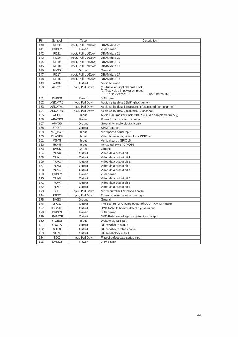
Pin Symbol Type Description 140 RD22 Inout, Pull Up/Down DRAM data 22 141 DVDD2 Power 2.5V power 142 RD21 Inout, Pull Up/Down DRAM data 21 143 RD20 Inout, Pull Up/Down DRAM data 20 144 RD19 Inout, Pull Up/Down DRAM data 19 145 RD18 Inout, Pull Up/Down DRAM data 18 146 DVSS Ground Ground 147 RD17 Inout, Pull Up/Down DRAM data 17 148 RD16 Inout, Pull Up/Down DRAM data 16 149 ABCK Output Audio bit clock 150 ALRCK Inout, Pull Down (1) Audio left/right channel clock
(2) Trap value in power-on reset. 1:use external 373, 0:use internal 373
151 DVDD3 Power 3.3V power 152 ASDATA0 Inout, Pull Down Audio serial data 0 (left/right channel) 153 ASDATA1 Inout, Pull Down Audio serial data 1 (surround left/surround right channel) 154 ASDATA2 Inout, Pull Down Audio serial data 2 (center/LFE channel) 155 ACLK Inout Audio DAC master clock (384/256 audio sample frequency) 156 APVDD3 Power Power for audio clock circuitry 157 APVSS Ground Ground for audio clock circuitry 158 SPDIF Output SPDIF output 159 MC_DAT Input Microphone serial input 160 BLANK# Inout Video blank area, active low / GPIO14 161 VSYN Inout Vertical sync / GPIO16 162 HSYN Inout Horizontal sync / GPIO15 163 DVSS Ground Ground 164 YUV0 Output Video data output bit 0 165 YUV1 Output Video data output bit 1 166 YUV2 Output Video data output bit 2 167 YUV3 Output Video data output bit 3 168 YUV4 Output Video data output bit 4 169 DVDD2 Power 2.5V power 170 YUV5 Output Video data output bit 5 171 YUV6 Output Video data output bit 6 172 YUV7 Output Video data output bit 7 173 ICE Input, Pull Down Microcontroller ICE mode enable 174 PRST Input, Pull Down Power on reset input, active high 175 DVSS Ground Ground 176 VFO13 Output The 1st, 3rd VFO pulse output of DVD-RAM ID header 177 IDGATE Output DVD-RAM ID header detect signal output 178 DVDD3 Power 3.3V power 179 UDGATE Output DVD-RAM recording data gate signal output 180 WOBSI Input Wobble signal input 181 SDATA Output RF serial data output 182 SDEN Output RF serial data latch enable 183 SLCK Output RF serial clock output 184 BDO Input, Pull Down Flag of defect data status input 185 DVDD3 Power 3.3V power
4-6
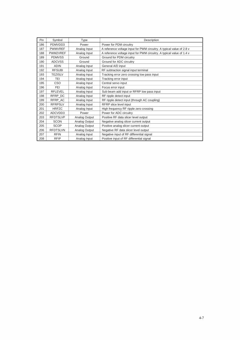
Pin Symbol Type Description 186 PDMVDD3 Power Power for PDM circuitry 187 PWMVREF Analog Input A reference voltage input for PWM circuitry. A typical value of 2.8 v 188 PWM2VREF Analog Input A reference voltage input for PWM circuitry. A typical value of 1.4 v 189 PDMVSS Ground Ground for PDM circuitry 190 ADCVSS Ground Ground for ADC circuitry 191 ADIN Analog Input General A/D input 192 RFSUBI Analog Input RF subtraction signal input terminal 193 TEZISLV Analog Input Tracking error zero crossing low pass input 194 TEI Analog Input Tracking error input 195 CSO Analog Input Central servo input 196 FEI Analog Input Focus error input 197 RFLEVEL Analog Input Sub beam add input or RFRP low pass input 198 RFRP_DC Analog Input RF ripple detect input 199 RFRP_AC Analog Input RF ripple detect input (through AC coupling) 200 RFRPSLV Analog Input RFRP slice level input 201 HRFZC Analog Input High frequency RF ripple zero crossing 202 ADCVDD3 Power Power for ADC circuitry 203 RFDTSLVP Analog Output Positive RF data slicer level output 204 SCON Analog Output Negative analog slicer current output 205 SCOP Analog Output Positive analog slicer current output 206 RFDTSLVN Analog Output Negative RF data slicer level output 207 RFIN Analog Input Negative input of RF differential signal 208 RFIP Analog Input Positive input of RF differential signal
4-7
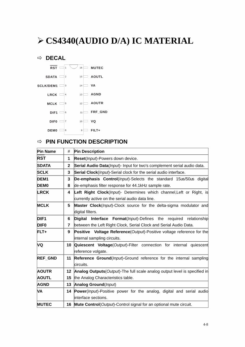
CS4340(AUDIO D/A) IC MATERIAL
DECAL 1
2
4
5
6
7
3
8 9
10
11
12
13
14
15
16RST
SDATA
SCLK/DEM1
LRCK
MCLK
DIF1
DIF0
DEM0 FILT+
VQ
FRF_GND
AOUTR
AGND
VA
AOUTL
MUTEC
PIN FUNCTION DESCRIPTION Pin Name # Pin Description RST 1 Reset(Input)-Powers down device. SDATA 2 Serial Audio Data(Input)- Input for two's complement serial audio data. SCLK 3 Serial Clock(Input)-Serial clock for the serial audio interface. DEM1 DEM0
3 8
De-emphasis Control(Input)-Selects the standard 15us/50us digital de-emphasis filter response for 44.1kHz sample rate.
LRCK 4 Left Right Clock(Input)- Determines which channel,Left or Right, is currently active on the serial audio data line.
MCLK 5 Master Clock(Input)-Clock source for the delta-sigma modulator and digital filters.
DIF1 DIF0
6 7
Digital Interface Format(Input)-Defines the required relationship between the Left Right Clock, Serial Clock and Serial Audio Data.
FLT+ 9 Positive Voltage Reference(Output)-Positive voltage reference for the internal sampling circuits.
VQ 10 Quiescent Voltage(Output)-Filter connection for internal quiescent reference volgate.
REF_GND 11 Reference Ground(Input)-Ground reference for the internal sampling circuits.
AOUTR AOUTL
12 15
Analog Outputs(Output)-The full scale analog output level is specified in the Analog Characteristics table.
AGND 13 Analog Ground(Input) VA 14 Power(Input)-Positive power for the analog, digital and serial audio
interface sections. MUTEC 16 Mute Control(Output)-Control signal for an optional mute circuit.
4-8
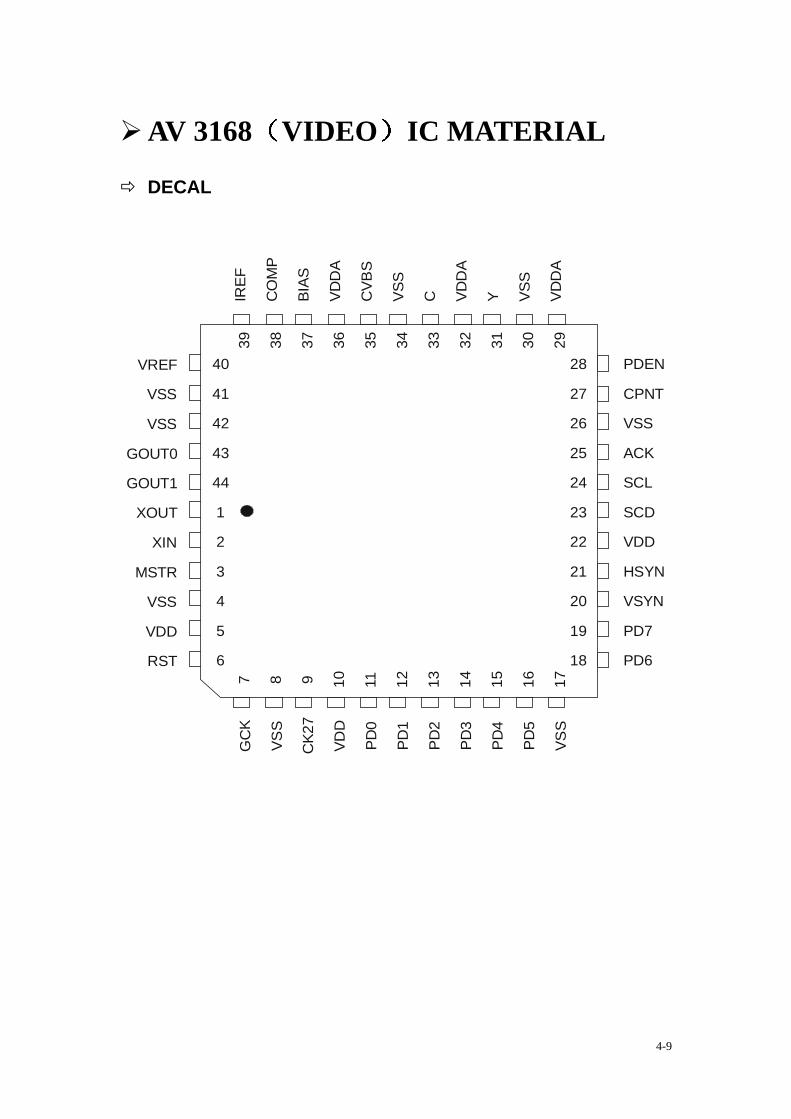
AV 3168 VIDEO IC MATERIAL
DECAL
VREF
VSS
VSS
GOUT0
GOUT1
XOUT
XIN
MSTR
VSS
VDD
RST
GC
K
VSS
CK2
7
VDD
PD0
PD1
PD2
PD3
PD4
PD5
VSS
PDEN
CPNT
VSS
ACK
SCL
SCD
VDD
HSYN
VSYN
PD7
PD6
IREF
CO
MP
BIAS
VDD
A
CVB
S
VSS
C VDD
A
Y VSS
VDD
A
40
41
42
43
44
1
2
3
4
5
6
7 8 9 10 11 12 13 14 15 16 17
28
27
26
25
24
23
22
21
20
19
18
39 38 37 36 35 34 33 32 31 30 29
4-9
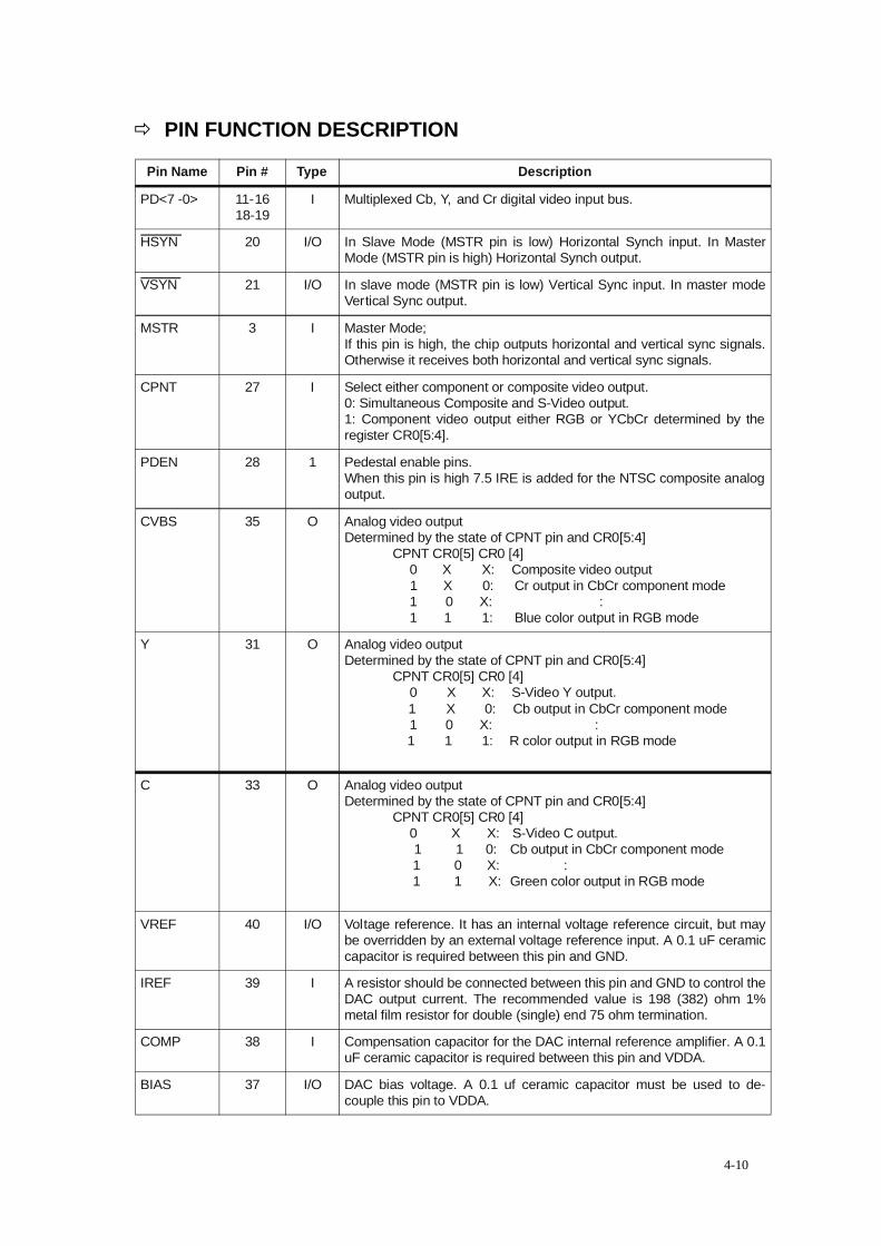
PIN FUNCTION DESCRIPTION
Pin Name Pin # Type Description
PD<7 -0> 11-16 18-19
I Multiplexed Cb, Y, and Cr digital video input bus.
HSYN 20 I/O In Slave Mode (MSTR pin is low) Horizontal Synch input. In MasterMode (MSTR pin is high) Horizontal Synch output.
VSYN 21 I/O In slave mode (MSTR pin is low) Vertical Sync input. In master modeVertical Sync output.
MSTR 3 I Master Mode; If this pin is high, the chip outputs horizontal and vertical sync signals.Otherwise it receives both horizontal and vertical sync signals.
CPNT 27 I Select either component or composite video output.0: Simultaneous Composite and S-Video output. 1: Component video output either RGB or YCbCr determined by theregister CR0[5:4].
PDEN 28 1 Pedestal enable pins.When this pin is high 7.5 IRE is added for the NTSC composite analogoutput.
CVBS 35 O Analog video outputDetermined by the state of CPNT pin and CR0[5:4]
CPNT CR0[5] CR0 [4]--- 0 ---- X------ X: ---Composite video output--- 1----- X------ 0: --- Cr output in CbCr component mode--- 1 ---0 0------X: --- 111111111 1- ::--- 1------1------ 1: ----Blue color output in RGB mode
Y 31 O Analog video output Determined by the state of CPNT pin and CR0[5:4]
CPNT CR0[5] CR0 [4]--- 0 ----- X----- X: ---S-Video Y output.--i 1------ X---- - 0: ---Cb output in CbCr component mode--- 1 ---0 0------X: -- 11111111 11- ::- i 1 ----- 1--- -- 1: - -R color output in RGB mode
C 33 O Analog video outputDetermined by the state of CPNT pin and CR0[5:4]
CPNT CR0[5] CR0 [4]--- 0 ------ X------X: --S-Video C output.---- 1 ------ 1-----0:---Cb output in CbCr component mode--1 1 ------ 0 ---- X:111111 1- ::--1 1 ------ 1------X:--Green color output in RGB mode
VREF 40 I/O Voltage reference. It has an internal voltage reference circuit, but maybe overridden by an external voltage reference input. A 0.1 uF ceramiccapacitor is required between this pin and GND.
IREF 39 I A resistor should be connected between this pin and GND to control theDAC output current. The recommended value is 198 (382) ohm 1%metal film resistor for double (single) end 75 ohm termination.
COMP 38 I Compensation capacitor for the DAC internal reference amplifier. A 0.1uF ceramic capacitor is required between this pin and VDDA.
BIAS 37 I/O DAC bias voltage. A 0.1 uf ceramic capacitor must be used to de-couple this pin to VDDA.
4-10
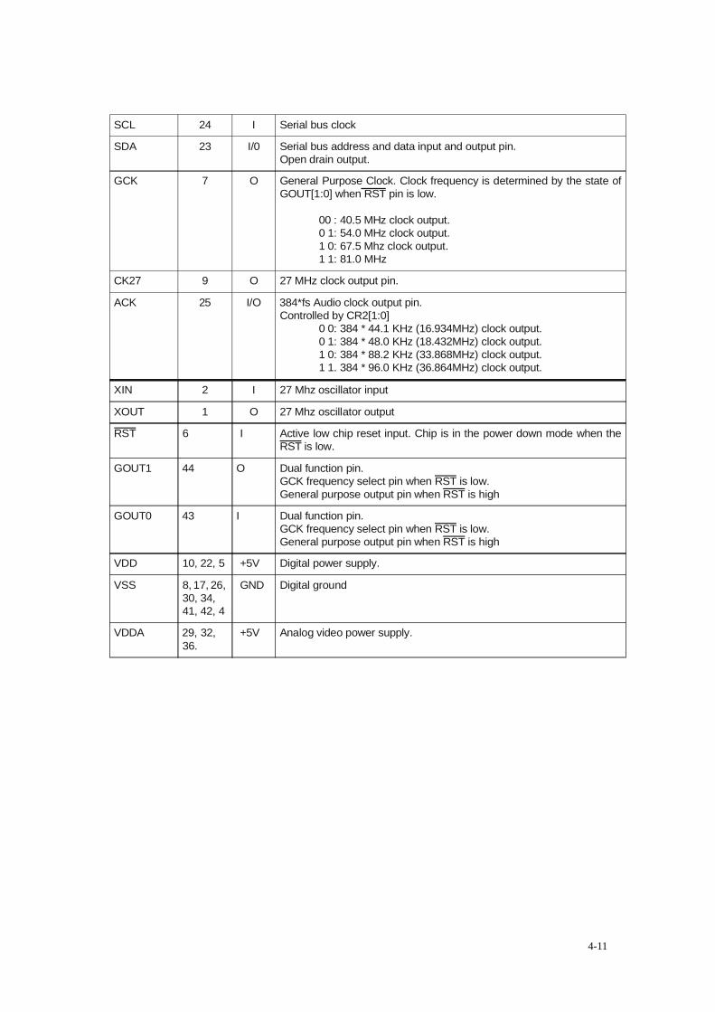
SCL 24 I Serial bus clock
SDA 23 I/0 Serial bus address and data input and output pin.Open drain output.
GCK 7 O General Purpose Clock. Clock frequency is determined by the state ofGOUT[1:0] when RST pin is low.
00 : 40.5 MHz clock output.0 1: 54.0 MHz clock output.1 0: 67.5 Mhz clock output.1 1: 81.0 MHz
CK27 9 O 27 MHz clock output pin.
ACK 25 I/O 384*fs Audio clock output pin.Controlled by CR2[1:0]
0 0: 384 * 44.1 KHz (16.934MHz) clock output.0 1: 384 * 48.0 KHz (18.432MHz) clock output.1 0: 384 * 88.2 KHz (33.868MHz) clock output.1 1. 384 * 96.0 KHz (36.864MHz) clock output.
XIN 2 I 27 Mhz oscillator input
XOUT 1 O 27 Mhz oscillator output
RST 6 I Active low chip reset input. Chip is in the power down mode when theRST is low.
GOUT1 44 O Dual function pin. GCK frequency select pin when RST is low.General purpose output pin when RST is high
GOUT0 43 I Dual function pin. GCK frequency select pin when RST is low.General purpose output pin when RST is high
VDD 10, 22, 5 +5V Digital power supply.
VSS 8, 17, 26, 30, 34, 41, 42, 4
GND Digital ground
VDDA 29, 32, 36.
+5V Analog video power supply.
4-11
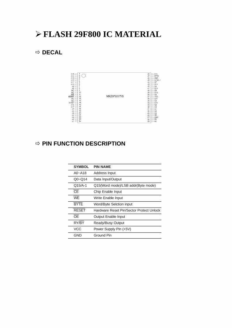
FLASH 29F800 IC MATERIAL
DECAL
PIN FUNCTION DESCRIPTION
SYMBOL PIN NAMEA0~A18 Address Input
Q0~Q14 Data Input/Output
Q15/A-1 Q15(Word mode)/LSB addr(Byte mode)
CE Chip Enable Input
WE Write Enable Input
BYTE Word/Byte Selction input
RESET Hardware Reset Pin/Sector Protect Unlock
OE Output Enable Input
RY/BY Ready/Busy Output
VCC Power Supply Pin (+5V)
GND Ground Pin
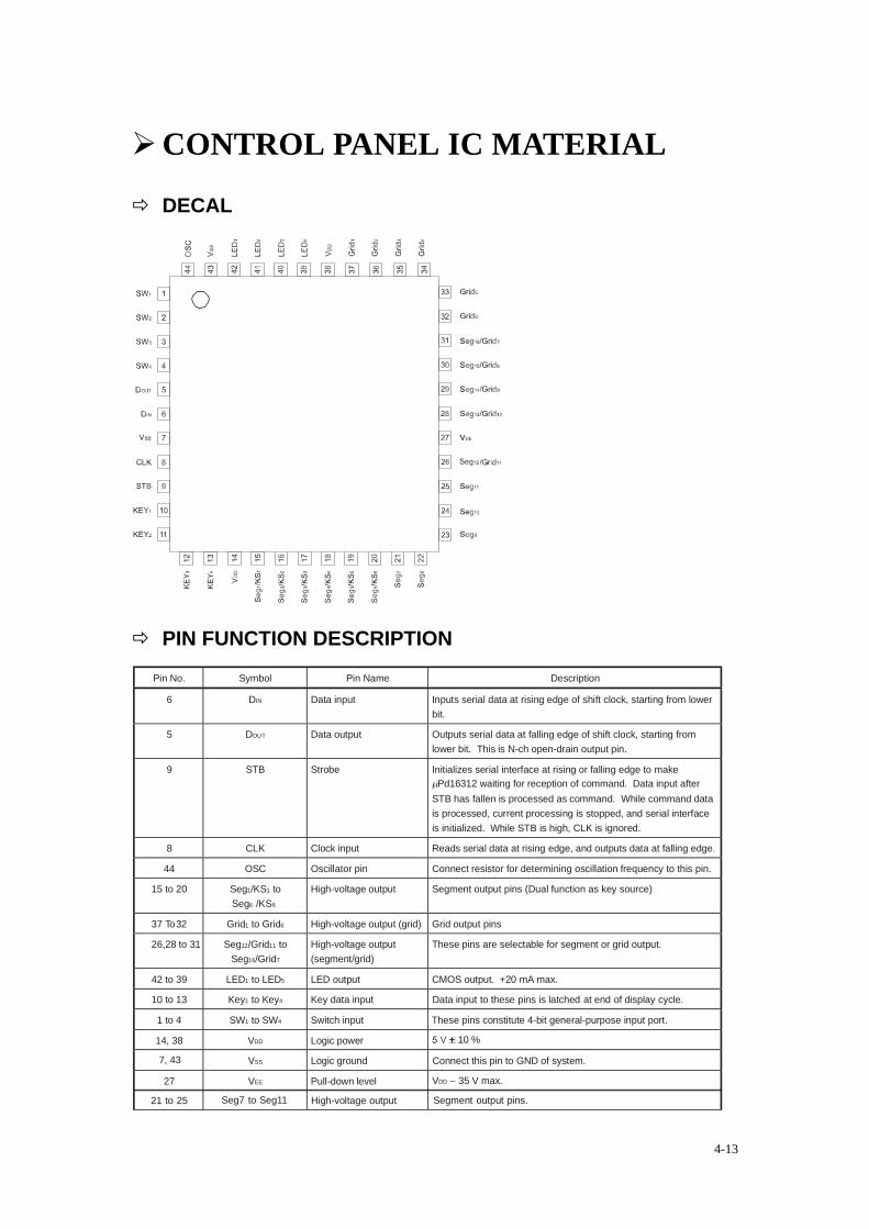
CONTROL PANEL IC MATERIAL
DECAL
PIN FUNCTION DESCRIPTION Pin No. Symbol Pin Name Description
6 DIN Data input Inputs serial data at rising edge of shift clock, starting from lowerbit.
5 DOUT Data output Outputs serial data at falling edge of shift clock, starting fromlower bit. This is N-ch open-drain output pin.
9 STB Strobe Initializes serial interface at rising or falling edge to makePd16312 waiting for reception of command. Data input after
STB has fallen is processed as command. While command datais processed, current processing is stopped, and serial interfaceis initialized. While STB is high, CLK is ignored.
8 CLK Clock input Reads serial data at rising edge, and outputs data at falling edge.
44 OSC Oscillator pin Connect resistor for determining oscillation frequency to this pin.
15 to 20 Seg1/KS1 toSeg6 /KS6
High-voltage output Segment output pins (Dual function as key source)
37 To 32 Grid1 to Grid6 High-voltage output (grid) Grid output pins
26,28 to 31 Seg12/Grid11 toSeg16/Grid7
High-voltage output(segment/grid)
These pins are selectable for segment or grid output.
42 to 39 LED1 to LED5 LED output CMOS output. +20 mA max.
10 to 13 Key1 to Key4 Key data input Data input to these pins is latched at end of display cycle.
1 to 4 SW1 to SW4 Switch input These pins constitute 4-bit general-purpose input port.
14, 38 VDD Logic power ± 10 %
7, 43 VSS Logic ground Connect this pin to GND of system.
27 VEE Pull-down level VDD − 35 V max.
21 to 25 Seg7 to Seg11 High-voltage output Segment output pins.
4-13
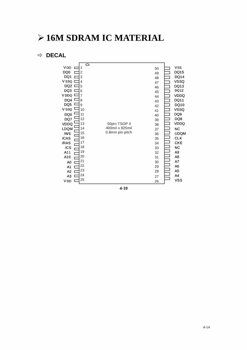
16M SDRAM IC MATERIAL
DECAL
VSSDQ15DQ14VSSQDQ13DQ12VDDQDQ11DQ10VSSQDQ9DQ8VDDQNCUDQMCLKCKENCA9A8A7A6A5A4VSS
12345678910111213141516171819202122232425
5049484746454443424140393837363534333231302928
V DDDQ0DQ1
V SSQDQ2DQ3
V DDQDQ4DQ5
V SSQDQ6
VDDQ
/WE/CAS/RAS
/CSA11A10
A0A1A2A3
V DD
50pin TSOP II400mil x 825mil0.8mm pin pitch
2726
DQ7
LDQM
4-10
4-14
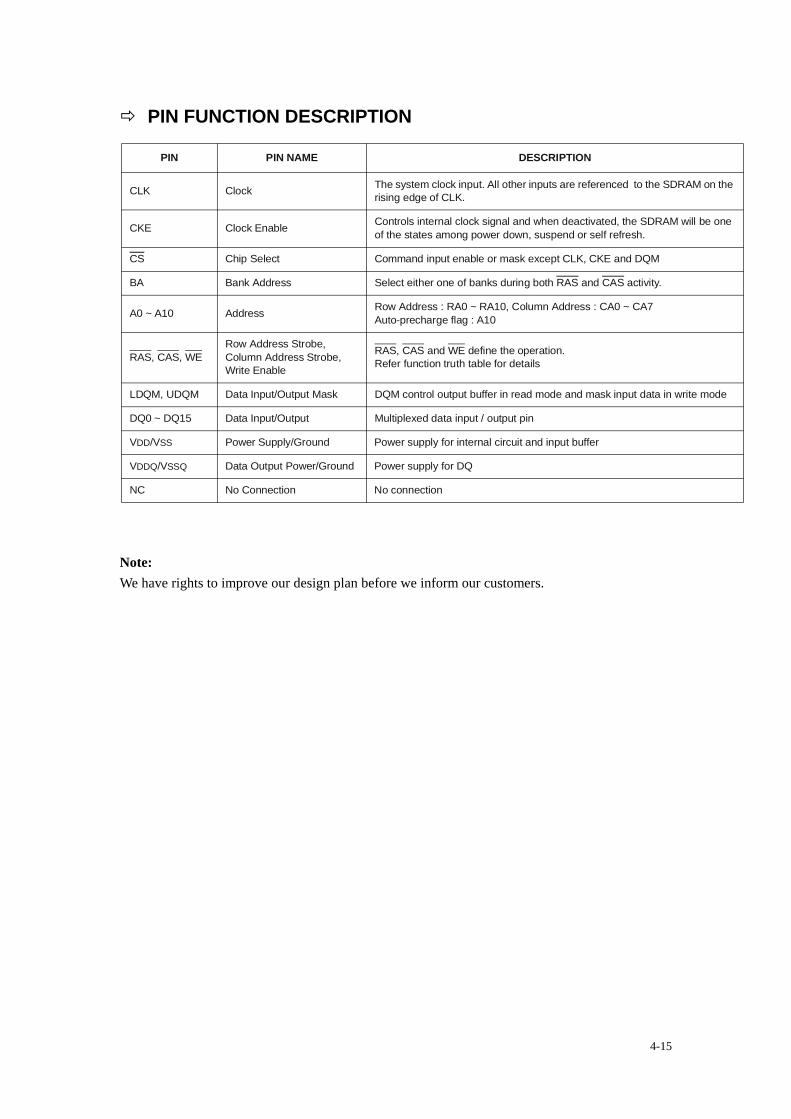
PIN FUNCTION DESCRIPTION
PIN PIN NAME DESCRIPTION
CLK Clock The system clock input. All other inputs are referenced to the SDRAM on the rising edge of CLK.
CKE Clock Enable Controls internal clock signal and when deactivated, the SDRAM will be one of the states among power down, suspend or self refresh.
CS Chip Select Command input enable or mask except CLK, CKE and DQM
BA Bank Address Select either one of banks during both RAS and CAS activity.
A0 ~ A10 Address Row Address : RA0 ~ RA10, Column Address : CA0 ~ CA7Auto-precharge flag : A10
RAS, CAS, WERow Address Strobe, Column Address Strobe, Write Enable
RAS, CAS and WE define the operation.Refer function truth table for details
LDQM, UDQM Data Input/Output Mask DQM control output buffer in read mode and mask input data in write mode
DQ0 ~ DQ15 Data Input/Output Multiplexed data input / output pin
VDD/VSS Power Supply/Ground Power supply for internal circuit and input buffer
VDDQ/VSSQ Data Output Power/Ground Power supply for DQ
NC No Connection No connection
Note: We have rights to improve our design plan before we inform our customers.
4-15