Embed Size (px)
Citation preview

Data Sheet
Sonar Interface Sludge Level Monitoring
Principle of OperationsThe ORCA Sonar Series transducer emits a high powered acoustic pulse, which is reflected from the interface density selected. The reflected signal is processed using specially developed software algorithms, that eliminate lighter floating densities and stratified layers, allowing measurement of “RAS” or “BED” levels. It can be calibrated to measure lighter densities like “FLOC” or one of the outputs could be used for a “CLARITY” output, similar to a basic turbidity transmitter measuring solids in suspension.
By choosing the correct sonar transducer frequency, the Orca sonar guarantees the optimized performance when measuring both light and heavy density interfaces.
Primary Areas of ApplicationsSewage & Wastewater
Primary Sedimentation – Blanket level.Secondary and final Clarifiers – RAS Blanket and fluff/pin floc layer.Thickeners and DAF – Bed level and clarity of water.Sequential Batch Reactors – Blanket monitoring (floating sonar).Lagoons – Bed sludge level.Lamella Clarifier – Bed level and floc level.
Mining / ProcessClarifiers, thickeners, CCD’s, settling ponds/lagoons, water treatment, carbon columns.
FunctionThe ORCA Series Sonar, sludge blanket and interface con-troller, consists of a microprocessor based transmitter, with easy menu driven programming via keypad, PC combina-tions or GSM modem, COMMS, GSM interface. The Orca controller works together with appropriate sonar transducer and transducer cleaning mechanism.
••
••
••
•
Features:Dual independent analogue outputs to track two different interfaces, or clarity simultaneously, with the one sonar sensor.Full range of sonar transducers to optimize detection of heavy and light density interfaces.Widest range of sonar frequencies to optimize performance.Easy calibration to track specific density inter-faces. eg: RAS blanket - 4g/l, floc/fluff layer - 1g/l.Industrial scum cleaning mechanisms, that do not require maintenance. No wiper blade assemblies.Control room graphics of tanks and interfaces.Wide range of communications: Devicenet, GosHawk, HART, Modbus, Profibus DP Foundation Fieldbus and Profibus PA
CDMA/GSM remote support capability for calibra-tion, commissioning or technical back-up.Relay alarms
•
•
•
•••
•••
•
•
A higher level of performance
- Sonar Sludge Level System
�Orca Sonar Series
Cutting Edge Sonar Technology
There are two major innovative changes between the First Generation instruments and the current Third Generation “ORCA” Hawk sonar range.
1. Sonar Transducer FrequenciesAll other existing sonar transmitters are described as be-ing First Generation technology. They utilize only one sonar transducer frequency and therefore have severe limitations in where they can be used successfully. An understanding of the Basic Physics of Sound Transmission, indicates that sound transmission through a liquid or gas, varies, based on the wavelength of the frequency transmitted.
When transmitting sound pulses through air, that may con-tain steam, condensation, dust etc the rule is to use a lower frequency, longer wavelength transducer to diffract the signal around particles in suspension. Its called the fog horn prin-ciple.
The same principle applies to transmitting sound through a liquid. When monitoring an interface in a process tank, like a secondary clarifier, the interface for controlling the RAS pumps, resides lower in the tank than the grey interface Fluff Layer. The First Generation sonar tries to stay on this heavier density RAS blanket by utilizing software algorithms. The problem is that as soon as the secondary tank has settling and bulking problems, the First Generation sonar monitors the interface going to the surface, so using software algorithms is not the total answer.
In our Third Generation Sonar range, the ORCA has “seven” different sonar transducer frequencies to choose from. De-pending on the application at the Waste Treatment Plant, we select the appropriate sonar transducer frequency, according to the density of the interface we want to control and monitor off.
This means that instead of having small signals (300milli-volts) reflecting off the desired density interface, the ORCA range has signals as large as 2500millivolts, almost 10 times greater, because of optimizing the sonar transducer frequen-cy. It also means, that when the secondary clarifier has bulk-ing and settling problems, the instrument continues to control off the RAS Blanket density, which still is at the bottom of the tank. It is only the lighter densities that are hydraulically lifted towards the launders at the top of the tank.
So we use a different sonar transducer frequency for each of the main applications at the Wastewater Treatment plant, Primary Sedimentation Tanks, Secondary/Final Clarifiers, Thickeners, and DAF Tanks.
Each ORCA sonar transducer has “smart” capability. They can be driven to output two different frequencies.
a. The Secondary Clarifier has two interfaces that are needed for optimizing the efficiency of the tank. The first is the RAS Blanket, that we generally monitor at a density of 4g/L, which guarantees a quality biomass return to the aeration lanes and
Comparison between First Generation and Third Generation Sonar Technology
to the Thickening area. This ensures that the RAS Blanket is not over pumped (over scavenged) and that we do not reduce the retention time in aeration by pumping in lower density biomass.
b. The second interface that we need to monitor is the Fluff Layer and we calibrate this density at 600 milligram/L. Under normal operating conditions in the Secondary Clarifier, the Fluff Layer at 600 milligrams/L sits about 1500mm above the RAS Density of 4g/L. By monitoring the two analogue outputs in the PLC we can identify how well the Secondary Clarifier is operating, because the two signals should rise and fall on the trend simultaneously if the tank is settling well. When a process problems occurs, perhaps caused by chang-ing industrial effluent entering the plant, causing a biological instability, bulking and settling problems occur. The RAS Blanket density is heavy enough not to rise, but the lighter Fluff Layer interface will be hydraulically lifted in the tank. The second analogue will indicate a change in settling pat-terns and an alarm can be raised in the PLC that the tank is experiencing settling problems.
c. This ensures that we not only control and optimize the RAS and the WAS densities, but we also provide early feedback to the process engineers and operators that one or more tanks have a process problem.
� Orca Sonar Series
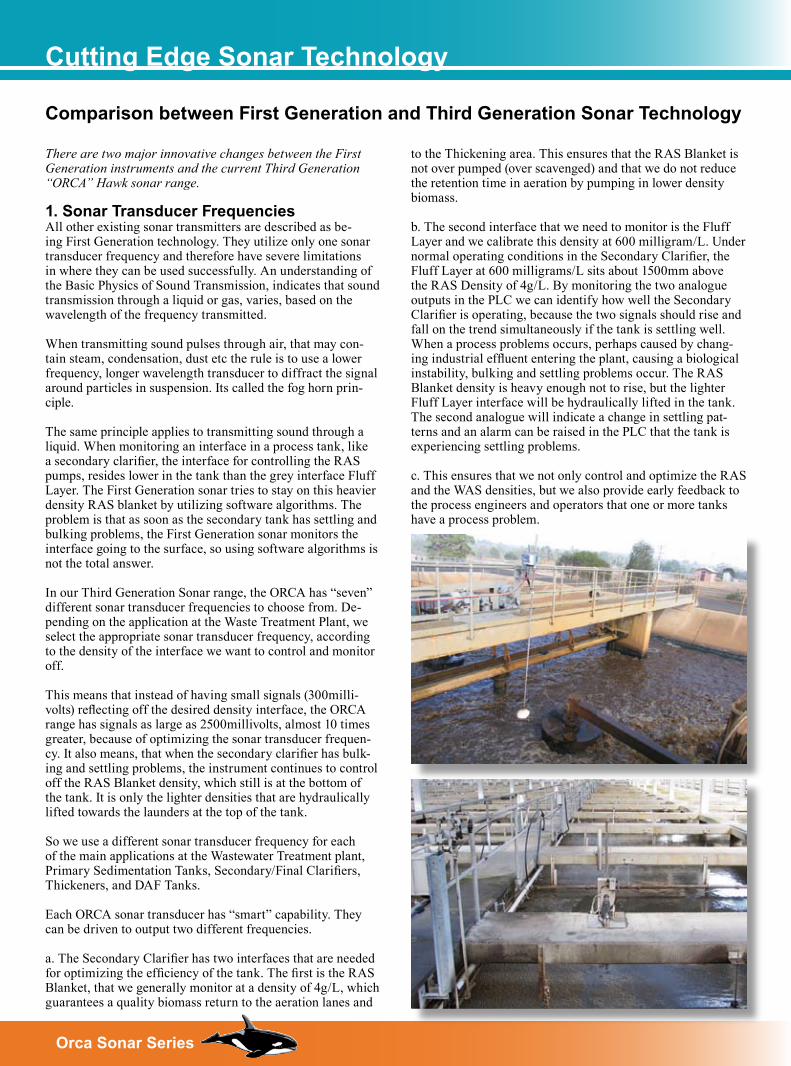
2. Special algorithms for controlling sonar interfaces, special scum cleaning capabili-ties a. Secondary Clarifiers can suffer with stratified interfaces, when process stability is lost. These stratified interfaces can confuse First Generation sonar transmitters into believing that the interface is higher in the tank than it really is. Our algorithms delete the stratified interface from being detected.
b. Some Secondary Clarifier tanks suffer from hydraulic imbalance to their inflow, when compared to other tanks close by. This causes a change in settling and monitoring of the interfaces, which the ORCA can handle with the minimum of calibration change. This is all the more reason that each Secondary Clarifier Tank should be treated as a sole stand alone process tank.
c. We have also developed a range of scum cleaners that are totally controlled by the ORCA transmitter. These cleaning mechanisms are an absolute necessity to our performance warranty. There is no known instrument that can survive, immersed in sewage media, that will work reliably without cleaning.
RAS Return Activated SludgeWAS Waste Activated SludgeDAF Dissolved Air FloatationLamella Type of clarifier designFluff Layer Light density interface secondary clarifierSBR Sequential Batch ReactorPinfloc Particles in suspensionClarity Clearness of liquidCCD Type of thickener-miningFloc Dosing Chemical dosing to improve settling
Glossery of Terms
�Orca Sonar Series
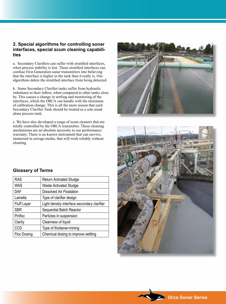
Typical Applications
Typically, the most difficult task when wanting to determine the level of an interface, lies in the correct selection of the transducer frequency.
There are many other variables to consider. They include particle size, flow, velocity, material, air bubble retention etc.
In general, the following should be undertaken:It is recommended always to use an automated cleaner.1. Identify a position away from direct inflow, where
turbulence is minimized.2. If air bubbles are present within heavy suspended solids,
use the scum cleaner.3. Position sonar transducer 1/3 radius from circumference
of the tank away from the influence of the feed well.4. Submerge the face of the selected transducer by a
minimum of 20mm (0.79”).
The higher the transducer frequency, the easier it becomes to see smaller particle sizes. The disadvantage, is the lack of penetration and a higher likelihood of air bubbles forming on the sensor face, creating impedance to the transmit and received signals.
Lower transducer frequencies will not see such small particles, but will see a more clearly defined interface.
The frequency selection should be based upon the % solids, plus a logical position for the placement of the sensor.Please consult your local distributor for correct transducer selection.
All sonar transducers will be affected by air bubble accumulation on the sensor face. If the auto cleaner is used, the system will operate to ensure accumulation of air bubble interface does not cause operational problems.
Transducer Selection Guidelines
Area FunctionsWater Treatment PlantPrimary Sedimentation Tank Floc level / sludge blanket levelSludge Thickener Tank Sludge bed level / clarity suspended solids / floc levelCalcium Hydroxide Reactor Sand/pellet bed levelSodium Hydroxide Reactor Sand/pellet bed levelSewage Treatment PlantPrimary Sedimentation Tank Sludge blanket level
Secondary / Final Clarifier RAS blanket level / rag/pinfloc layer / clarity suspended solidsSludge Thickener Tank Sludge bed level / clarity suspended solids“DAF” Tank Sludge bed level / floating sludge levelSequential Batch Reactor (SBR) Settling bed level / RAS blanket levelIndustrial (food, paper etc.)Primary Sedimentation Tank Sludge blanket levelSecondary Clarifier Tank RAS blanket level / clarity suspended solids / rag/pinfloc layerThickener Tank Sludge bed level / clarity suspended solids / floc level“DAF” Tank Sludge bed level / floating sludge levelSequential Batch Reactor (SBR) Settling blanket level / RAS bed levelCarbon Column Carbon bed levelMining/Mineral processingClarifier Tank Blanket level / clarity suspended solids / stratified floc layersThickener Tank Sludge bed level / clarity suspended solids / stratified floc layersCCD’s Tank Sludge bed level / clarity suspended solids / stratified floc layersSettling Ponds Sludge bed level
� Orca Sonar Series
Special Application
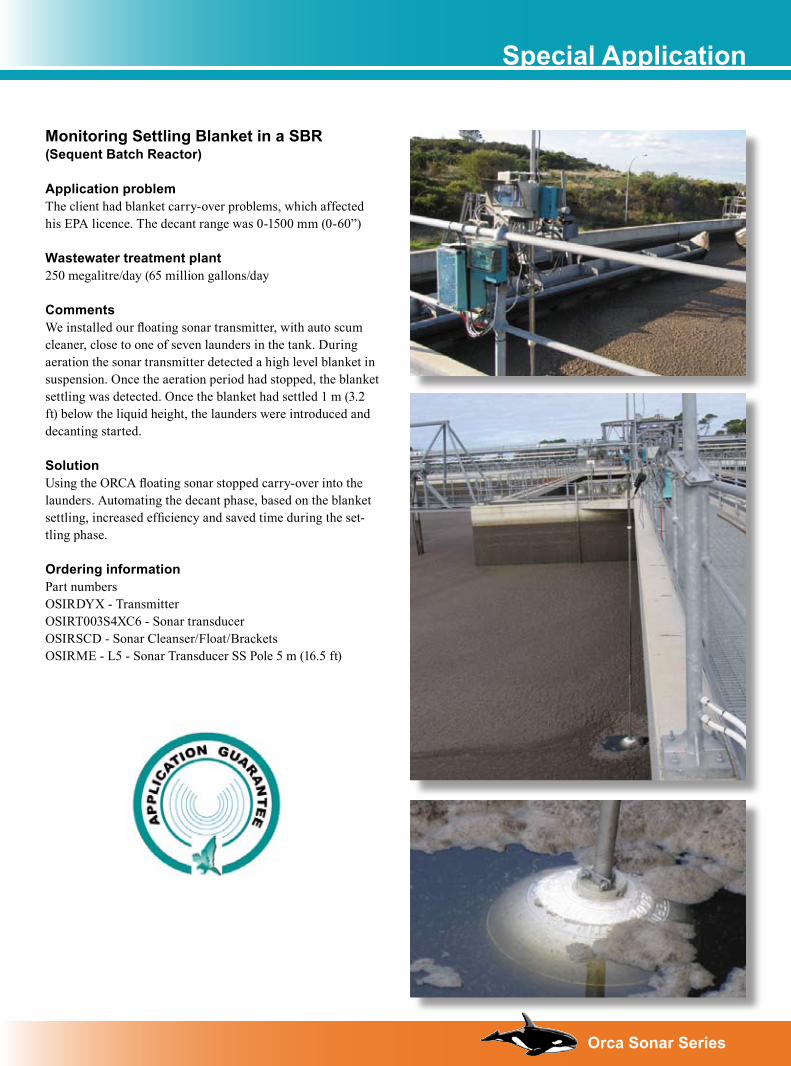
Monitoring Settling Blanket in a SBR(Sequent Batch Reactor)
Application problemThe client had blanket carry-over problems, which affected his EPA licence. The decant range was 0-1500 mm (0-60”)
Wastewater treatment plant 250 megalitre/day (65 million gallons/day
Comments We installed our floating sonar transmitter, with auto scum cleaner, close to one of seven launders in the tank. During aeration the sonar transmitter detected a high level blanket in suspension. Once the aeration period had stopped, the blanket settling was detected. Once the blanket had settled 1 m (3.2 ft) below the liquid height, the launders were introduced and decanting started.
SolutionUsing the ORCA floating sonar stopped carry-over into the launders. Automating the decant phase, based on the blanket settling, increased efficiency and saved time during the set-tling phase.
Ordering informationPart numbers OSIRDYX - TransmitterOSIRT003S4XC6 - Sonar transducerOSIRSCD - Sonar Cleanser/Float/BracketsOSIRME - L5 - Sonar Transducer SS Pole 5 m (16.5 ft)
�Orca Sonar Series
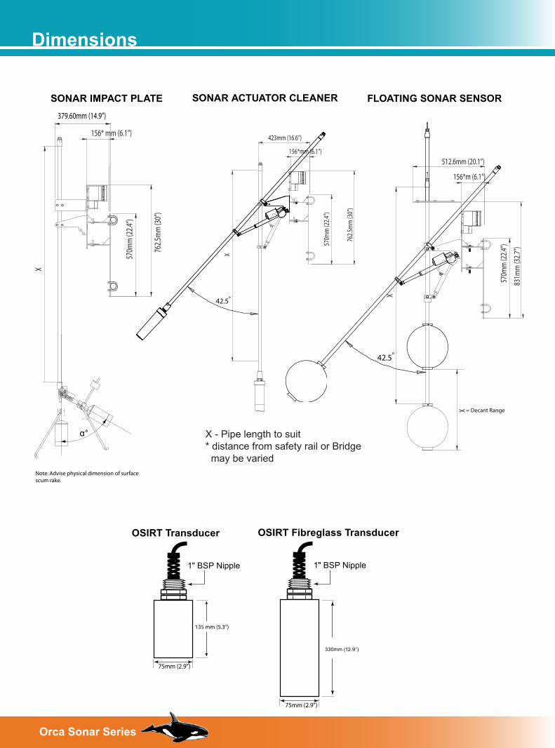
Dimensions
FLOATING SONAR SENSORSONAR ACTUATOR CLEANERSONAR IMPACT PLATE
X - Pipe length to suit* distance from safety rail or Bridge may be varied
570m
m (2
2.4”)
762.5
mm
(30”
)
156* mm (6.1”)
X
379.60mm (14.9”)
α°
570m
m (2
2.4”
)
762.
5mm
(30”
)
156*mm (6.1”)
423mm (16.6”)
X
42.5o
570m
m (2
2.4”
)
831m
m (3
2.7”
)
156*m (6.1”)
512.6mm (20.1”)
X
X
42.5o
OSIRT Transducer
1" BSP Nipple
75mm (2.9”)
OSIRT Fibreglass Transducer
1" BSP Nipple
75mm (2.9”)
135 mm (5.3”)
330mm (12.9”)
= Decant Range
Note: Advise physical dimension of surface scum rake.
� Orca Sonar Series
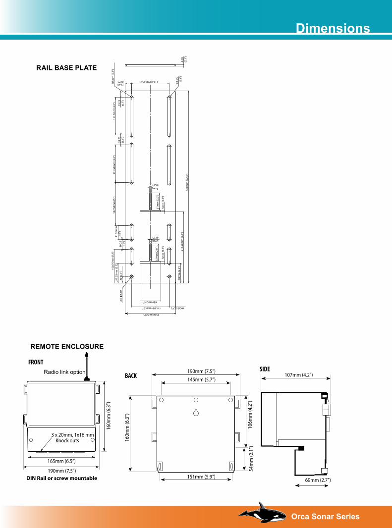
Dimensions
REMOTE ENCLOSURE
BACK
FRONT
3 x 20mm, 1x16 mm Knock outs
DIN Rail or screw mountable
SIDE
165mm (6.5”)
190mm (7.5”)
160m
m (6
.3”)
160m
m (6
.3”)
190mm (7.5”)145mm (5.7”)
106m
m (4
.2”)
54m
m (2
.1”)
151mm (5.9”)
107mm (4.2”)
69mm (2.7”)
Radio link option
RAIL BASE PLATE
4.00
(0.1
”)
28.7
5(1
.1”)
29.2
5(1
.1”)
41.5
0mm
(1.6
”)20
(0.7
”)
111.
50m
m (4
.3”)
111.50mm (4.3”)
8.50
111.
50 m
(4.3
”)59
.25m
m (2
.3”)
570m
m (2
2.4”
)
19.2
5(0
.7”)
19.25(0.7”)
100.
75m
m (3
.9)
2x
5mm
(0.2
”)
4.25
(0.1
”)
150mm (5.9”)
111.50mm (4.3”)
62mm (2.4”)
5mm(0.2”)
5mm(0.2”)
19.25 (0.7”)
60m
m (2
.3”)
211.
50m
m (8
.3”)
51m
m (2
.0”)
51m
m (0
.2”)
5mm
(0.2
”)5m
m (0
.2”)
R R
127.
50m
m (5
”)
�Orca Sonar Series
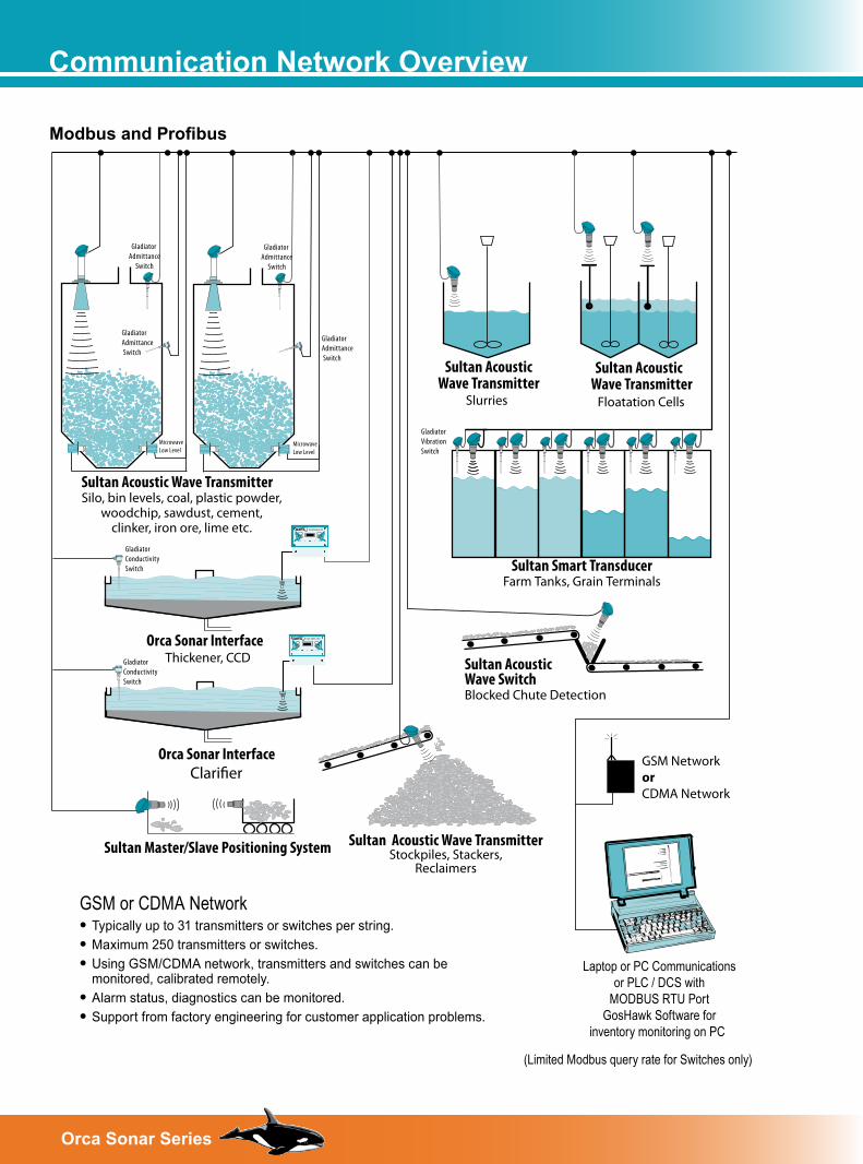
Communication Network Overview
Modbus and Profibus
Laptop or PC Communicationsor PLC / DCS with
MODBUS RTU PortGosHawk Software for
inventory monitoring on PC
GSM NetworkorCDMA Network
Floatation Cells
Sultan AcousticWave Transmitter
Slurries
GladiatorAdmittance Switch
Sultan Acoustic Wave TransmitterSilo, bin levels, coal, plastic powder,
woodchip, sawdust, cement,clinker, iron ore, lime etc.
Orca Sonar InterfaceThickener, CCD
GSM or CDMA Network• Typically up to 31 transmitters or switches per string.• Maximum 250 transmitters or switches.• Using GSM/CDMA network, transmitters and switches can be
monitored, calibrated remotely.• Alarm status, diagnostics can be monitored.• Support from factory engineering for customer application problems.
Sultan Acoustic Wave TransmitterStockpiles, Stackers,
Reclaimers
Sultan AcousticWave SwitchBlocked Chute Detection
Sultan Smart TransducerFarm Tanks, Grain Terminals
Orca Sonar Interface Clari�er
SULTAN 234
SULTAN 234
Gladiator Admittance
Switch
Gladiator VibrationSwitch
GladiatorAdmittance Switch
Gladiator Admittance
Switch
MicrowaveLow Level
MicrowaveLow Level
Sultan Master/Slave Positioning System
GladiatorConductivitySwitch
GladiatorConductivitySwitch
(Limited Modbus query rate for Switches only)
Sultan AcousticWave Transmitter
� Orca Sonar Series
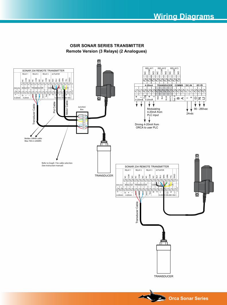
Wiring Diagrams
OSIR SONAR SERIES TRANSMITTERRemote Version (3 Relays) (2 Analogues)
Modulating4-20mA fromPLC input
Driving 4-20mA fromORCA to user PLC
+Is –4-20mA
AC-IN
+–
DC-IN
RELAY1 RELAY2 RELAY3
4-20mA COMMSTRANSDUCER
1 LN4-20mA+ –
24vdc
90 - 260vac
NC
CO
M
NO
NC
CO
M
NO
NC
CO
M
NO
RE
D
BLK
BLU
E
WH
ITE
Test
in
B A
SONAR 234 REMOTE TRANSMITTER
- - ++
RELAY 1 RELAY 2 RELAY 3 ACTUATOR
NC COM
NO NC COM
NO NC COM
NO BLK
BLU
BRN
GRN
YEL
SHLD
ANALOG1 TRANSDUCER COMMS DC-IN AC-IN
RE
D
BLK
BLU
WH
T
Te
st B A N L1
4-20mA 12-30VDC 90-265 VACIs+ -
4-20mA
BO
TTO
M
TOP
Pot
Cab
le
Mot
or C
able
TRANSDUCER
Tran
sduc
er C
able
ANALOG2
Belden 3084A cableMax 700 m (2000ft)
Refer to Graph 1 for cable selection(See instruction manual)
JunctionBox
SONAR 234 REMOTE TRANSMITTER
- - ++
RELAY 1 RELAY 2 RELAY 3 ACTUATOR
NC COM
NO NC COM
NO NC COM
NO BLK
BLU
BRN
GRN
YEL
SHLD
ANALOG1 TRANSDUCER COMMS DC-IN AC-IN
RE
D
BLK
BLU
WH
T
Te
st B A N L1
4-20mA 12-30VDC 90-265 VACIs+ -
4-20mA
BO
TTO
M
TOP
TRANSDUCER
Tran
sduc
er C
able
ANALOG2
10Orca Sonar Series
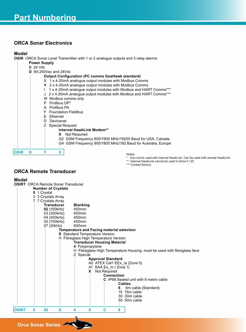
Part Numbering
ORCA Sonar Electronics Model OSIR ORCA Sonar Level Transmitter with 1 or 2 analogue outputs and 3 relay alarms Power Supply B 24 Vdc D 90-250Vac and 24Vdc Output Configuration (PC comms GosHawk standard) X 1 x 4-20mA analogue output modules with Modbus Comms Y 2 x 4-20mA analogue output modules with Modbus Comms I 1 x 4-20mA analogue output modules with Modbus and HART Comms*** J 2 x 4-20mA analogue output modules with Modbus and HART Comms*** W Modbus comms only P Profibus DP* A Profibus PA F Foundation Fieldbus E Ethernet D Devicenet Z Special Request Internal HawkLink Modem** X Not Required G2 GSM Frequency 800/1900 MHz/19200 Baud for USA, Canada G4 GSM Frequency 900/1800 MHz/192 Baud for Australia, Europe OSIR D Y X
ORCA Remote Transducer
Model OSIRT ORCA Remote Sonar Transducer Number of Crystals 0 1 Crystal 3 3 Crystals Array 7 7 Crystals Array Transducer Blanking 02 (150kHz) 450mm 03 (300kHz) 450mm 04 (450kHz) 450mm 05 (700kHz) 450mm 07 (30kHz) 600mm Temperature and Facing material selection S Standard Temperature Version H Fibreglass High Temperature Version Transducer Housing Material 4 Polypropylene H Fibreglass High Temperature Housing, must be used with fibreglass face Z Special Approval Standard A0 ATEX Cat1 EEx_ia (Zone 0) A1 SAA Ex_m ( Zone 1) X Not Required Connection C IP68 Sealed unit with 6 metre cable Cables 6 6m cable (Standard) 15 15m cable 30 30m cable 50 50m cable OSIRT 0 02 S 4 X C 6
Notes: * Can not be used with internal HawkLink. Can be used with remote HawkLink.** Internal HawkLink cannot be used in Zone 0 / 20*** Contact factory
11 Orca Sonar Series
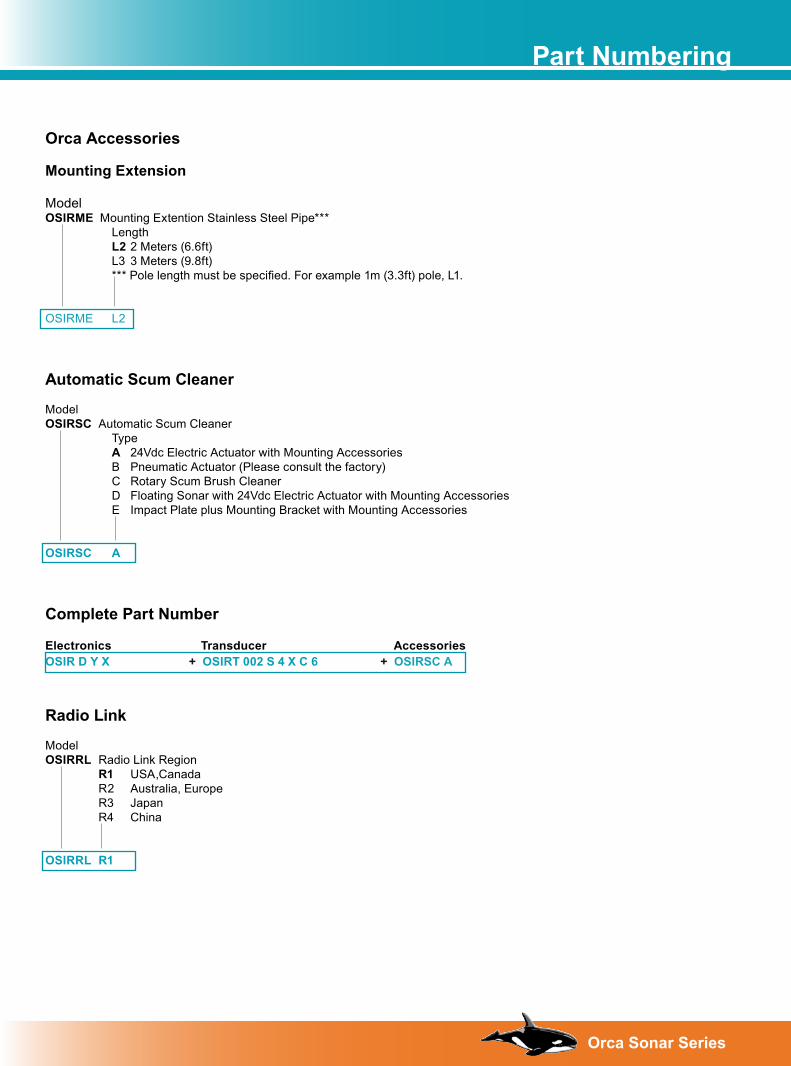
Radio Link
Model OSIRRL Radio Link Region R1 USA,Canada R2 Australia, Europe R3 Japan R4 China
OSIRRL R1
Orca Accessories
Mounting Extension
Model OSIRME Mounting Extention Stainless Steel Pipe*** Length L2 2 Meters (6.6ft) L3 3 Meters (9.8ft) *** Pole length must be specified. For example 1m (3.3ft) pole, L1. OSIRME L2
Automatic Scum Cleaner
Model OSIRSC Automatic Scum Cleaner Type A 24Vdc Electric Actuator with Mounting Accessories B Pneumatic Actuator (Please consult the factory) C Rotary Scum Brush Cleaner D Floating Sonar with 24Vdc Electric Actuator with Mounting Accessories E Impact Plate plus Mounting Bracket with Mounting Accessories
OSIRSC A
Complete Part Number
Electronics Transducer AccessoriesOSIR D Y X + OSIRT 002 S 4 X C 6 + OSIRSC A
Part Numbering
1�Orca Sonar Series
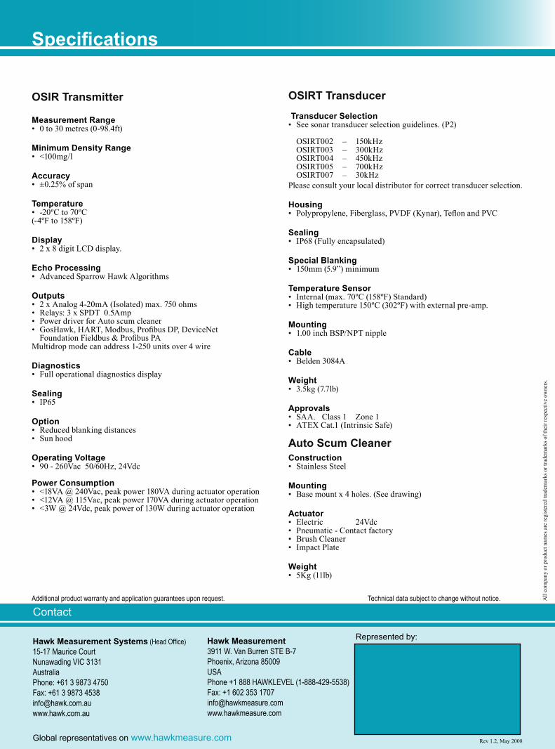
Hawk Measurement Systems (Head Office)15-17 Maurice CourtNunawading VIC 3131AustraliaPhone: +61 3 9873 4750Fax: +61 3 9873 [email protected]
Contact
Hawk Measurement 3911 W. Van Burren STE B-7Phoenix, Arizona 85009USAPhone +1 888 HAWKLEVEL (1-888-429-5538)Fax: +1 602 353 [email protected]
Global representatives on www.hawkmeasure.com
Represented by:
Rev 1.2, May 2008
OSIR Transmitter
Measurement Range• 0 to 30 metres (0-98.4ft)
Minimum Density Range• <100mg/l
Accuracy• ±0.25% of span
Temperature• -20ºC to 70ºC(-4ºF to 158ºF)
Display• 2 x 8 digit LCD display.
Echo Processing• Advanced Sparrow Hawk Algorithms
Outputs• 2 x Analog 4-20mA (Isolated) max. 750 ohms• Relays: 3 x SPDT 0.5Amp• Power driver for Auto scum cleaner• GosHawk, HART, Modbus, Profibus DP, DeviceNet
Foundation Fieldbus & Profibus PAMultidrop mode can address 1-250 units over 4 wire
Diagnostics• Full operational diagnostics display
Sealing• IP65
Option• Reduced blanking distances• Sun hood
Operating Voltage• 90 - 260Vac 50/60Hz, 24Vdc
Power Consumption• <18VA @ 240Vac, peak power 180VA during actuator operation• <12VA @ 115Vac, peak power 170VA during actuator operation• <3W @ 24Vdc, peak power of 130W during actuator operation
OSIRT Transducer Transducer Selection
• See sonar transducer selection guidelines. (P2)
OSIRT002 – 150kHz OSIRT003 – 300kHz OSIRT004 – 450kHz OSIRT005 – 700kHz OSIRT007 – 30kHzPlease consult your local distributor for correct transducer selection.
Housing• Polypropylene, Fiberglass, PVDF (Kynar), Teflon and PVC
Sealing• IP68 (Fully encapsulated)
Special Blanking• 150mm (5.9”) minimum
Temperature Sensor• Internal (max. 70ºC (158ºF) Standard) • High temperature 150ºC (302ºF) with external pre-amp.
Mounting• 1.00 inch BSP/NPT nipple
Cable• Belden 3084A
Weight• 3.5kg (7.7lb)
Approvals• SAA. Class 1 Zone 1 • ATEX Cat.1 (Intrinsic Safe)
Auto Scum Cleaner Construction • Stainless Steel
Mounting • Base mount x 4 holes. (See drawing)
Actuator• Electric 24Vdc• Pneumatic - Contact factory• Brush Cleaner• Impact Plate
Weight• 5Kg (11lb)
Specifications
Additional product warranty and application guarantees upon request. Technical data subject to change without notice. All
com
pany
or p
rodu
ct n
ames
are
regi
ster
ed tr
adem
arks
or t
rade
mar
ks o
f the
ir re
spec
tive
owne
rs.


![2012 Ch 5-1 Reactors [__ __]](https://img.pdfslide.tips/doc/110x75/577cc66d1a28aba7119e2bb1/2012-ch-5-1-reactors-.jpg)

![Sistem Berkas[sequential]](https://img.pdfslide.tips/doc/110x75/5571f97949795991698fa6ee/sistem-berkassequential.jpg)