Embed Size (px)
Citation preview

1
Database Systems
November 2, 2011
1
Lecture #7
topobo (mit)

2
Announcement
• Assignment #2 due today
• Assignment #3 out today & due on 11/16.Assignment #3 out today & due on 11/16.
• Midterm exam in class next week.– Cover Chapters 1, 2<except 2.7>, 3, 4.1, 4.2, 5
3
Structure of DBMS
• Disk Space Manager
M ( )
Applications
– Manage space (pages) on disk.
• Buffer Manager
– Manage traffic between disk and main memory. (bring in pages from disk to main
Query Optimizationand Execution
Relational Operators
Files and Access Methods
Queries
4
memory).
• File and Access Methods
– Organize records into pages and files.
Buffer Manager
Disk Space Manager

3
Storing Data: Disks and Files
Chapter 9
5
Disks and Files
• DBMS stores information on (“hard”) disks.
• This has major performance implications for DB system design!• This has major performance implications for DB system design!– READ: transfer data from disk to main memory (RAM).
– WRITE: transfer data from RAM to disk.
– Both are high‐cost operations, relative to in‐memory operations, so must be planned carefully!
6

4
Why Not Store Everything in Main Memory?
• Costs too much. – NTD 8,000 for 8G of SDRAM (1,000 per 1GB)– NTD 4,000 for 1,000 GB of HD (4 per 1GB)
• Main memory is volatile. – We want data to be saved between runs.
• Typical storage hierarchy:– Main memory (RAM) for currently used data.– Disk for the main database (secondary storage).– Tapes for archiving older versions of the data (backup storage) or just
disk to disk backup
7
disk‐to‐disk backup.
Disks
• Secondary storage device of choice. – Main advantage over tapes: random access vs. sequential.g p q
• Tapes are for data backup, not for operational data.– Access the last byte in a tape requires winding through the entire tape.
• Data is stored and retrieved in units called disk blocks or pages.
• Unlike RAM, time to retrieve a disk page varies depending upon location on disk.
8
– Therefore, relative placement of pages on disk has major impact on DBMS performance!
5
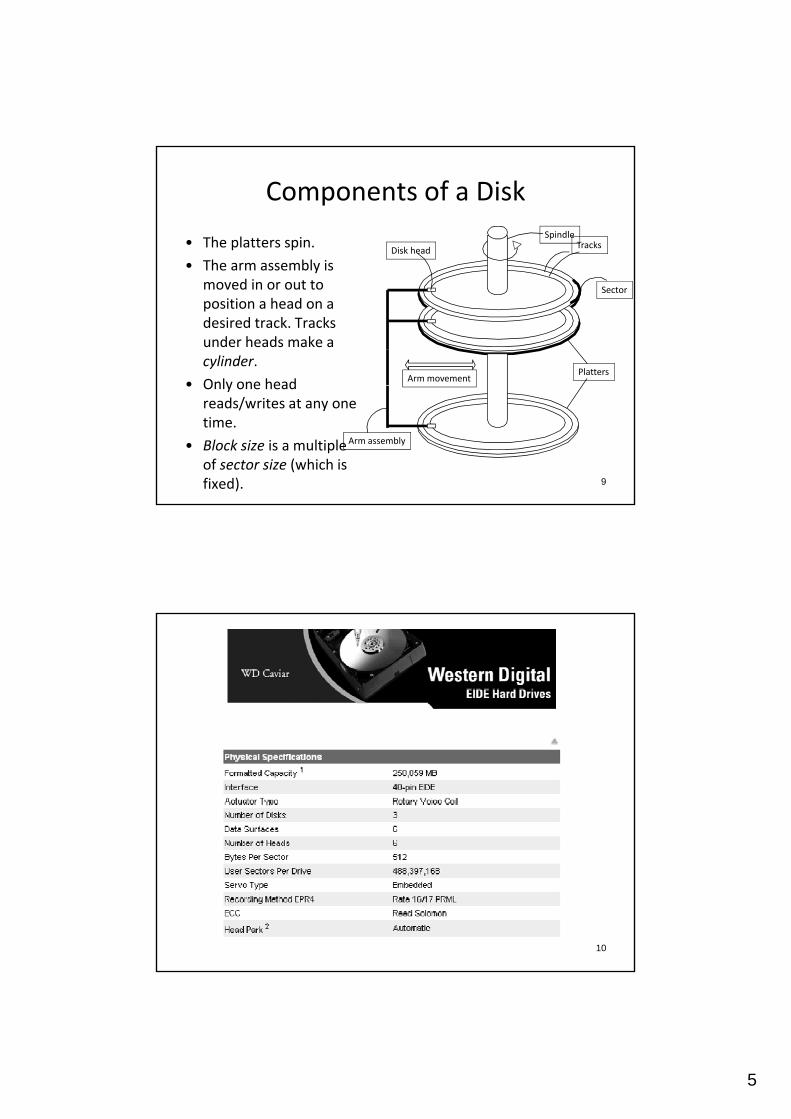
Components of a Disk
• The platters spin.
• The arm assembly is
Spindle
Disk headTracks
• The arm assembly is moved in or out to position a head on a desired track. Tracks under heads make a cylinder.
• Only one headPlatters
Arm movement
Sector
9
• Only one head reads/writes at any one time.
• Block size is a multiple of sector size (which is fixed).
Arm assembly
10

6
Accessing a Disk Page
• Time to access (read/write) a disk block is called access titime.
• It is a sum of:– seek time (moving arm to position disk head on right track)
– rotational delay (waiting for block to rotate under head)
– transfer time (actually moving data to/from disk surface)
• Seek time and rotational delay (mechanical parts)
11
dominate the access time– Seek time varies from about 1 to 20msec (avg 10msec)
– Rotational delay varies from 0 to 8msec (avg. 4msec)
– Transfer rate is about 100MBps (0.025msec per 4KB page)
12

7
How to reduce I/O cost?
• access time = seek time + rotational latency + transfer titime
• How to lower I/O cost?– Reduce seek/rotation delays!
• How to reduce seek/rotational delays for a large I/O requests of many pages?
13
– If two pages of records are accessed together frequently, put them close together on disk.
Arranging Pages on Disk
• Next block concept (measure the closeness of blocks)( ) ( )– (1) blocks on same track (no movement of arm), followed by
– (2) blocks on same cylinder (switch head, but almost no movement of arm), followed by
– (3) blocks on adjacent cylinder (little movement of arm)
• Blocks in a file should be arranged sequentially on disk (by `next’), to minimize seek and rotational delay.
F ti l f t hi l t ti
14
• For a sequential scan, pre‐fetching several pages at a time is a big win!

8
Spindle
Disk headTracks
Next Block Concept
Platters
Sector
1
2
3
15
PlattersArm movement
Arm assembly
RAID
• RAID = Redundant Arrays of Independent (Inexpensive) Disks– Disk Array: Arrangement of several disks that gives abstraction of aDisk Array: Arrangement of several disks that gives abstraction of a
single, large disk.
• Goals: Increase performance and reliability.– Say you have D disks & each I/O request wants D blocks
• How to improve the performance (data transfer rate)?
– Say you have D disks & D number of I/O request each wanting one block
16
• How to improve the performance (request service rate)?
– Say you have D disks and at most one disk can fail at any time
• How to improve reliability (in case of disk failure)?

9
Two main techniques in RAID
• Data striping improves performance.– Data (e.g., in the same time file) is partitioned across multiple HDs; ( g ) p p
size of a partition is called the striping unit.
– Performance gain is from reading/writing multiple HDs at the same time.
• Redundancy improves reliability. – Data striping lowers reliability: More disks →more failures.
– Store redundant information on different disks. When a disk fails, you can reconstruct data from other disks.
17
RAID Levels
• Level 0: No redundancy (only data striping)
• Level 1: Mirrored (two identical copies)• Level 1: Mirrored (two identical copies)
• Level 0+1: Striping and Mirroring
• (Level 2: Error‐Correcting Code)
• Level 3: Bit‐Interleaved Parity
• Level 4: Block‐Interleaved Parity
• Level 5: Block‐Interleaved Distributed Parity
18
y
• (Level 6: Error‐Correcting Code)
• More Levels (01‐10, 03/30, …)
10
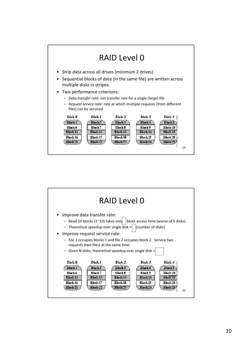
RAID Level 0
• Strip data across all drives (minimum 2 drives)
• Sequential blocks of data (in the same file) are written across multiple disks in stripes.
• Two performance criterions:– Data transfer rate: net transfer rate for a single (large) file
– Request service rate: rate at which multiple requests (from different files) can be serviced
19
RAID Level 0
• Improve data transfer rate:– Read 10 blocks (1~10) takes only 2‐block access time (worse of 5 disks).
– Theoretical speedup over single disk = N (number of disks)
• Improve request service rate:– File 1 occupies blocks 1 and file 2 occupies block 2. Service two
requests (two files) at the same time.
– Given N disks, theoretical speedup over single disk = N.
20
11
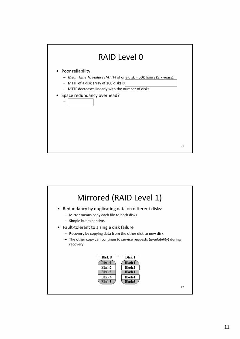
RAID Level 0
• Poor reliability:– Mean Time To Failure (MTTF) of one disk = 50K hours (5.7 years).
– MTTF of a disk array of 100 disks is 50K/100 = 500 hours (21 days)!
– MTTF decreases linearly with the number of disks.
• Space redundancy overhead? – No overhead
21
Mirrored (RAID Level 1)• Redundancy by duplicating data on different disks:
– Mirror means copy each file to both disks
– Simple but expensive.Simple but expensive.
• Fault‐tolerant to a single disk failure– Recovery by copying data from the other disk to new disk.
– The other copy can continue to service requests (availability) during recovery.
22

12
Mirrored (RAID Level 1)
• Performance is not the objective, but reliability.– Mirroring frequently used when availability is more important than g q y y p
storage efficiency.
• Data transfer rate:– Write performance may be slower than single disk, why?
• Worse of 2 disks
– Read performance can be faster than single disk, why?• Consider reading block 1 from
disk 0 and block 2 from disk
23
1 at the same time.
– Compare read performance
to RAID Level 0?
• Better, but why? 3579
46810
Mirrored (RAID Level 1)
• Data reliability:– Assume Mean‐Time‐To‐Repair (MTTR) is 1 hour.Assume Mean Time To Repair (MTTR) is 1 hour.
• Shorter with Hotswap HDs.
– MTTF of Mirrored 2‐disks = 1 / (probability that 2 disks will fail within the same hour) = MTTR2/2 = (50K) 2/2 hours = many many years.
• Space redundancy overhead:– 50% overhead
24

13
Striping and Mirrors (RAID 0+1)
Disk 5 Disk 6 Disk 7 Disk 8 Disk 9
25
Bit‐Interleaved Parity (RAID Level 3)
• Fine‐grained striping at the bit level
• One parity disk:• One parity disk:– Parity bit value = XOR across all data bit values
• If one disk fails, recover the lost data: – XOR across all good data bit values and parity bit value
0 1 10
26
0?
10
11
00

14
Bit‐Interleaved Parity (RAID Level 3)
• Performance:
T f t d ?
• Reliability:
C t l t 1 di k– Transfer rate speedup?• x32 of single disk
– Request service rate improvement?• Same as single disk (do one request at a time)
– Can tolerate 1 disk failure.
• Space overhead:
– One parity disk (1/33 overhead)
27
Block‐Interleaved Parity (RAID Level 4)
• Coarse‐grained striping at the block levelOtherwise it is similar to RAID 3– Otherwise, it is similar to RAID 3
• If one disk fails, recovery the lost block:
– Read same block of all disks (including parity disk) to reconstruct the lost block.
28

15
Block‐Interleaved Parity (RAID Level 4)
• Performance:– If error, read/write of same block on all disks (worse‐of‐N on one block)If error, read/write of same block on all disks (worse of N on one block)
– If no error, write also needs to update (read‐n‐write) the parity block. (no need to read other disks)
• Can compute new parity based on old data, new data, and old parity
• New parity = (old data XOR new data) XOR old parity
– Result in bottleneck on the parity disk! (can do only one write at a time)
• How to remove this bottleneck?
29
Block‐Interleaved Parity (RAID Level 4)
• Reliability:
C t l t 1 di k f il– Can tolerate 1 disk failure.
• Space redundancy overhead:
– 1 parity disk
30
16
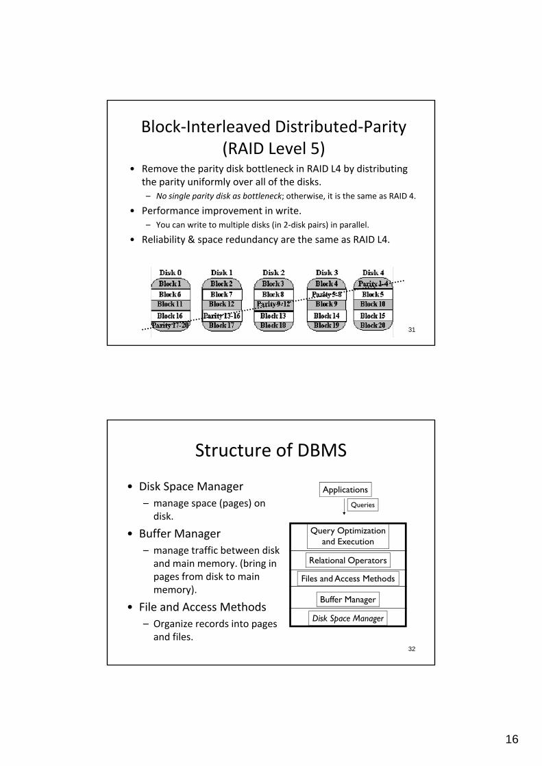
Block‐Interleaved Distributed‐Parity (RAID Level 5)
• Remove the parity disk bottleneck in RAID L4 by distributing the parity uniformly over all of the disksthe parity uniformly over all of the disks. – No single parity disk as bottleneck; otherwise, it is the same as RAID 4.
• Performance improvement in write.– You can write to multiple disks (in 2‐disk pairs) in parallel.
• Reliability & space redundancy are the same as RAID L4.
31
Structure of DBMS
• Disk Space Manager
( )
Applications
– manage space (pages) on disk.
• Buffer Manager
– manage traffic between disk and main memory. (bring in pages from disk to main
Query Optimizationand Execution
Relational Operators
Files and Access Methods
Queries
32
memory).
• File and Access Methods
– Organize records into pages and files.
Buffer Manager
Disk Space Manager
17
Disk Space Manager
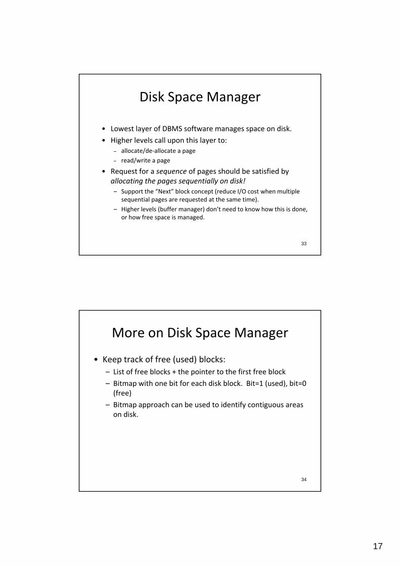
• Lowest layer of DBMS software manages space on disk.
• Higher levels call upon this layer to:– allocate/de‐allocate a page
– read/write a page
• Request for a sequence of pages should be satisfied by allocating the pages sequentially on disk! – Support the “Next” block concept (reduce I/O cost when multiple
33
sequential pages are requested at the same time).
– Higher levels (buffer manager) don’t need to know how this is done, or how free space is managed.
More on Disk Space Manager
• Keep track of free (used) blocks:
Li t f f bl k + th i t t th fi t f bl k– List of free blocks + the pointer to the first free block
– Bitmap with one bit for each disk block. Bit=1 (used), bit=0 (free)
– Bitmap approach can be used to identify contiguous areas on disk.
34
18
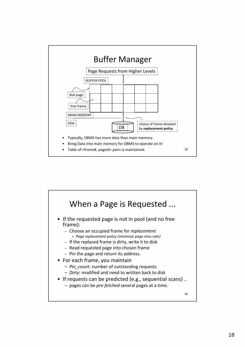
Buffer ManagerPage Requests from Higher Levels
BUFFER POOL
MAIN MEMORY
disk page
free frame
35
• Typically, DBMS has more data than main memory.
• Bring Data into main memory for DBMS to operate on it!
• Table of <frame#, pageid> pairs is maintained.
DBDISK choice of frame dictated
by replacement policy
When a Page is Requested ...
• If the requested page is not in pool (and no free frame):)– Choose an occupied frame for replacement
• Page replacement policy (minimize page miss rate)
– If the replaced frame is dirty, write it to disk– Read requested page into chosen frame– Pin the page and return its address.
• For each frame, you maintain
36
– Pin_count: number of outstanding requests– Dirty: modified and need to written back to disk
• If requests can be predicted (e.g., sequential scans) ..– pages can be pre‐fetched several pages at a time.
19
More on Buffer Manager
• Requestor of page must unpin it (no longer need it), and indicate whether the page has been modified:and indicate whether the page has been modified:
– dirty bit is used for this.
• Page in pool may be requested many times,
– a pin count is used. A page is a candidate for replacement iff pin count = 0.
37
Buffer Replacement Policy
• Frame is chosen for replacement by a replacement policy:– FIFO, MRU, Random, etc. Which policy is considered as the best?FIFO, MRU, Random, etc. Which policy is considered as the best?
• Least‐recently‐used (LRU): have LRU queue of frames with pin_count = 0
• What is the overhead of implementing LRU?
• Clock (approximate LRU with less overhead)– Use an additional reference_bit per page; set to 1 when the frame is
accessed
– Clock handmoving from frame 0 to frame n.
38
g
– Reset reference_bit of recently accessed frames.
– Replace frame(s) with reference_bit = 0 & pin_count = 0.
• Policy can have big impact on # of I/O’s; depends on the access pattern.

20
Clock Algorithm ExamplePin_count=0
Clock Hand
disk page
free frame
BUFFER POOL
1
1 10
0
39
LRU may not be good: Sequential Flooding
• #buffer frames = 2
• #pages in a file = 3 (P1, P2, P3)Block
dFrame #1
Frame #2#pages in a file 3 (P1, P2, P3)
• Use LRU + repeated sequential scans
• What many page I/O replacements?
• Repeated scan of file– # buffer frames < # pages in file
read #1 #2
P1 P1
P2 P1 P2
P3 P3 P2
P1 P3 P1
40
– Every scan of the file result in reading every page of the file.
P2 P2 P1
P3 P2 P3
21
DBMS vs. OS File System
• OS also does disk space & buffer mgmt.
• Why not let OS manage these tasks?• Why not let OS manage these tasks?– Better predict the page reference patterns & pre‐fetch pages. • Adjust replacement policy, and pre‐fetch pages based on access patterns in typical DB operations.
– Pin a page in memory and force a page to disk.
41
• Differences in OS support: portability issues
– Maintain a virtual file that spans multiple disks.
Files of Records
• Higher levels of DBMS operate on records, and files of records.f
• FILE: A collection of pages, each containing a collection of records. Must support:– Insert/delete/modify record(s)– Read a particular record (specified using record id)– Scan all records (possibly with some conditions on the records to be retrieved)
42
• To support record level operations, we must keep track of:– Fields in a record: Record format– Records on a page: Page format– Pages in a file: File format
22
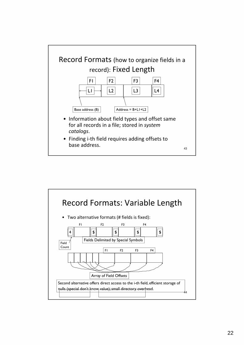
F1 F2 F3 F4
Record Formats (how to organize fields in a record): Fixed Length
L1 L2 L3 L4
F1 F2 F3 F4
• Information about field types and offset same
Base address (B) Address = B+L1+L2
43
• Information about field types and offset same for all records in a file; stored in system catalogs.
• Finding i‐th field requires adding offsets to base address.
Record Formats: Variable Length
• Two alternative formats (# fields is fixed):
F1 F2 F3 F4
Fields Delimited by Special Symbols
4 $ $ $ $
FieldCount
F1 F2 F3 F4
44
Second alternative offers direct access to the i-th field, efficient storage of nulls (special don’t know value); small directory overhead.
Array of Field Offsets

23
Page Formats (How to store records in a page):Fixed Length Records
Slot 1Slot 2
Slot 1Slot 2
Slot N
. . . . . .
N M10. . .
M ... 3 2 1
PACKED
Slot N
FreeSpace
Slot M
11
number number
45
• Record id = <page id, slot #>.
• They differ on how deletion (which creates a hole) is handled.
• In first alternative, shift remaining records to fill hole => changes rid; may not be acceptable given external reference.
PACKED UNPACKED, BITMAPof records of slots
Page Formats: Variable Length Records
Page iRid = (i,N)
Rid = (i,2)
Rid = (i 1)
* Slot directory contains
Rid = (i,1)
Pointerto startof freespace
N . . . 2 1
20 16 24 N
# slots
46
y
one slot per record.
* Each slot contains (record offset, record length)
* Deletion is by setting the record offset to ‐1.
* Can move records on page without changing rid (change the record offset, but same slot number); so, attractive for fixed‐length records.
pSLOT DIRECTORY

24
Unordered (Heap) Files
• Simplest file structure contains records in no particular dorder.
• As file grows and shrinks, disk pages are allocated and de‐allocated.
• How would you implement a heap file (data structure)?– Double‐Linked lists
– Page directory
47
Heap File (Doubly Linked Lists)
HeaderPage
DataPage
DataPage
DataPage
DataPage
DataPage
DataPage Pages with
Free Space
Full Pages
48
• The header page id and Heap file name must be stored someplace.
• Each page contains 2 `pointers’ plus data.
• The problem is that inserting a variable size record requires walking through free space list to find a page with enough space.
25
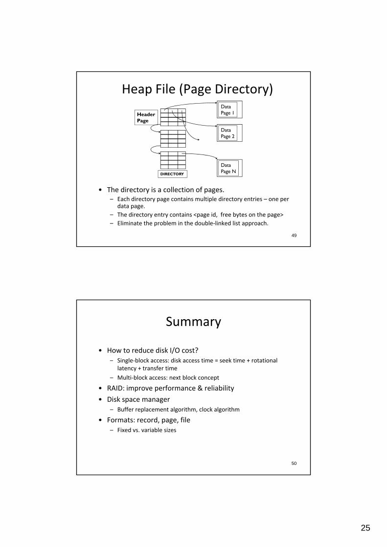
Heap File (Page Directory)DataPage 1
Data
HeaderPage
• The directory is a collection of pages
DataPage 2
DataPage N
DIRECTORY
49
• The directory is a collection of pages.– Each directory page contains multiple directory entries – one per
data page.
– The directory entry contains <page id, free bytes on the page>
– Eliminate the problem in the double‐linked list approach.
Summary
• How to reduce disk I/O cost?– Single‐block access: disk access time = seek time + rotational
latency + transfer time
– Multi‐block access: next block concept
• RAID: improve performance & reliability
• Disk space manager– Buffer replacement algorithm, clock algorithm
50
• Formats: record, page, file– Fixed vs. variable sizes