Embed Size (px)
Citation preview
Datasheet
System Overview
Document 1077785 Rev. C (Aug 2011)
Overview
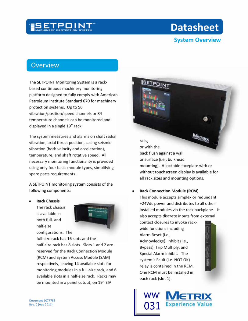
The SETPOINT Monitoring System is a rack‐
based continuous machinery monitoring
platform designed to fully comply with American
Petroleum Institute Standard 670 for machinery
protection systems. Up to 56
vibration/position/speed channels or 84
temperature channels can be monitored and
displayed in a single 19” rack.
The system measures and alarms on shaft radial
vibration, axial thrust position, casing seismic
vibration (both velocity and acceleration),
temperature, and shaft rotative speed. All
necessary monitoring functionality is provided
using only four basic module types, simplifying
spare parts requirements.
A SETPOINT monitoring system consists of the
following components:
Rack Chassis
The rack chassis
is available in
both full‐ and
half‐size
configurations. The
full‐size rack has 16 slots and the
half‐size rack has 8 slots. Slots 1 and 2 are
reserved for the Rack Connection Module
(RCM) and System Access Module (SAM)
respectively, leaving 14 available slots for
monitoring modules in a full‐size rack, and 6
available slots in a half‐size rack. Racks may
be mounted in a panel cutout, on 19” EIA
rails,
or with the
back flush against a wall
or surface (i.e., bulkhead
mounting). A lockable faceplate with or
without touchscreen display is available for
all rack sizes and mounting options.
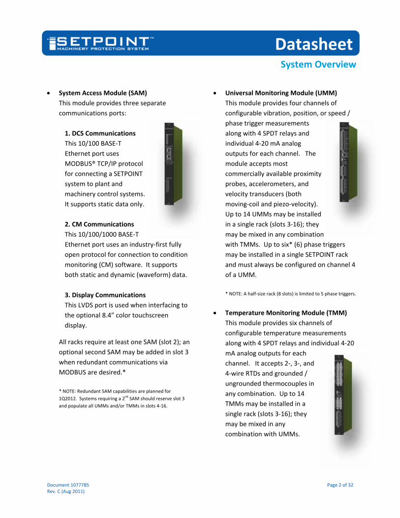
Rack Connection Module (RCM)
This module accepts simplex or redundant
+24Vdc power and distributes to all other
installed modules via the rack backplane. It
also accepts discrete inputs from external
contact closures to invoke rack‐
wide functions including
Alarm Reset (i.e.,
Acknowledge), Inhibit (i.e.,
Bypass), Trip Multiply, and
Special Alarm Inhibit. The
system’s Fault (i.e. NOT OK)
relay is contained in the RCM.
One RCM must be installed in
each rack (slot 1).
Datasheet
System Overview
Document 1077785 Page 2 of 32 Rev. C (Aug 2011)
System Access Module (SAM)
This module provides three separate
communications ports:
1. DCS Communications
This 10/100 BASE‐T
Ethernet port uses
MODBUS® TCP/IP protocol
for connecting a SETPOINT
system to plant and
machinery control systems.
It supports static data only.
2. CM Communications
This 10/100/1000 BASE‐T
Ethernet port uses an industry‐first fully
open protocol for connection to condition
monitoring (CM) software. It supports
both static and dynamic (waveform) data.
3. Display Communications
This LVDS port is used when interfacing to
the optional 8.4” color touchscreen
display.
All racks require at least one SAM (slot 2); an
optional second SAM may be added in slot 3
when redundant communications via
MODBUS are desired.*
* NOTE: Redundant SAM capabilities are planned for
1Q2012. Systems requiring a 2nd SAM should reserve slot 3
and populate all UMMs and/or TMMs in slots 4‐16.
Universal Monitoring Module (UMM)
This module provides four channels of
configurable vibration, position, or speed /
phase trigger measurements
along with 4 SPDT relays and
individual 4‐20 mA analog
outputs for each channel. The
module accepts most
commercially available proximity
probes, accelerometers, and
velocity transducers (both
moving‐coil and piezo‐velocity).
Up to 14 UMMs may be installed
in a single rack (slots 3‐16); they
may be mixed in any combination
with TMMs. Up to six* (6) phase triggers
may be installed in a single SETPOINT rack
and must always be configured on channel 4
of a UMM.
* NOTE: A half‐size rack (8 slots) is limited to 5 phase triggers.
Temperature Monitoring Module (TMM)
This module provides six channels of
configurable temperature measurements
along with 4 SPDT relays and individual 4‐20
mA analog outputs for each
channel. It accepts 2‐, 3‐, and
4‐wire RTDs and grounded /
ungrounded thermocouples in
any combination. Up to 14
TMMs may be installed in a
single rack (slots 3‐16); they
may be mixed in any
combination with UMMs.

Datasheet
System Overview
Document 1077785 Page 3 of 32 Rev. C (Aug 2011)
Rack Configuration Software
This software allows configuration of all
modules in a rack by connecting to the USB
port on any
UMM or TMM.
Future
connectivity is
planned to
allow remote
configuration of the rack over a secure
control network via the 10/100 BASE‐T
communications port on the SAM. A copy of
this software is provided with each system
free‐of‐charge. It can also be downloaded
from our website.
Integral Backlit Touchscreen Display
Both half‐ and full‐size racks can be ordered
with an optional 8.4” color touchscreen
display. The
display mounts
on the rack’s
lockable
faceplate and
provides all rack
statuses and channel values on a single
screen. It also allows the user to access
detailed channel data, the system events
list, and the system alarm list. The display
fully complies with API 670 requirements.
External Power Supply (EPS)
The SETPOINT system is energized using
standard +24 Vdc instrument power, readily
available in many plants.
In such installations, no
external power supply
is required. Simply
connect one or two
(when optional
redundancy is required)
24 Vdc power source(s)
to the Rack Connection
Module (RCM). For installations with
110/220 Vac, 90‐350 Vdc, 400 Vac 3‐PH, or
500 Vac 3‐PH power sources, an external
power supply (EPS) is used. Each EPS is
mounted via 35mm DIN rail external to the
rack enclosure.
Weatherproof Housing
NEMA 4X / IP65 stainless steel housings with
lockable see‐through doors are available for
both half‐ and full‐size SETPOINT systems.
These housings provide protection from
dust, moisture, and corrosion when racks
are mounted at the machine deck or in
other industrial environments not suited for
unprotected instrumentation. When only a
door is required, it can be ordered without
the complete housing. The housings and
doors are designed to fit over the top of the
SETPOINT system’s lockable faceplate and
touchscreen display. Weatherproof
housings and/or doors are ordered
separately. Refer to datasheet 1078951.

Datasheet
System Overview
Document 1077785 Page 4 of 32 Rev. C (Aug 2011)
I.S. Barriers
The SETPOINT system is approved* for use
in hazardous areas up to Div 2 / Zone 2.
When transducers will be installed in Div 1 /
Zone 1 areas, the SETPOINT system must be
located in a safe area, or a Div 2 / Zone 2
area. Intrinsic Safety (I.S.) barriers are then
used to limit the
available energy
on the transducer
signal and power
connections. The
SETPOINT system
supports the use
of both passive
(zener) and active
(isolated) barriers.
* Pending. Expected 4Q2011.
Condition Monitoring Software
The SETPOINT
system is the first
to offer a fully open
protocol for access to both static and
dynamic (waveform) data. This open
connectivity allows the SETPOINT system to
enjoy native integration with OSIsoft’s PI®
System software. Through our partnership
with OSIsoft, users will be able to connect
their SETPOINT system directly to PI
software for comprehensive trending and
diagnostic displays of all data, including plot
types such as orbit, spectrum, timebase, and
more.*
* Availability planned for 1Q2012.

Datasheet
System Overview
Document 1077785 Page 5 of 32 Rev. C (Aug 2011)
Features and Benefits
Deep experience
The Metrix team designing the SETPOINT
system possesses deep experience gained
through developing and sustaining more
than four generations of successive API 670‐
compliant machinery protection systems.
We pay attention to every detail, ensuring
the system works the way you need it to
work in the real world – where details
matter.
Robust, rugged construction
The SETPOINT rack chassis is constructed
entirely of industrial‐grade anodized
aluminum and stainless steel – every card
guide, every faceplate, every rack panel. In
addition to excellent RFI/EMI rejection,
these materials are built to last while
maintaining their good looks. The SETPOINT
system looks professional because it is
professional.
Easily adaptable mounting
The SETPOINT system’s design allows the
same rack to be used in panel cutout, 19”
EIA, or bulkhead mounting configurations by
simply employing different rack brackets.
The chassis, backplane, and all modules
remain the same. This also means that you
don’t sacrifice valuable space when
bulkhead mounting – unlike systems that
require twice as much space for bulkhead
mounting compared to rack or panel
mounting.
Front‐loading, front‐wired modules
Every module in the SETPOINT system
inserts from the front and all field wiring
lands on removable connectors at the front
of the rack, no matter which mounting
option you choose. No more back‐and‐forth
trips around the panel to access each side of
the rack during installation and
maintenance. And, everything is neatly
recessed behind the SETPOINT system’s
attractive, lockable faceplate, protecting
your critical wiring.
High quality, high‐speed backplane
The SETPOINT system uses state‐of‐the‐art
backplane connectors and high‐speed
design techniques to facilitate ultra‐fast data
throughput and outstanding reliability.
Full color, backlit touchscreen
With the SETPOINT system’s optional
touchscreen, users have at‐a‐glance, real
time visibility of every channel and status in
the rack on a single screen – no scrolling, no
multiplexing. We worked closely with users
to ensure the system’s display was intuitive,
efficient, and attractive, with a rapid update
time so there’s no annoying wait for the
screen to refresh with current values. It’s
also easy to see under all lighting conditions
– including outdoors. And, because it uses
resistive (not capacitive) technology, it
works with fingers, gloves, and stylus.

Datasheet
System Overview
Document 1077785 Page 6 of 32 Rev. C (Aug 2011)
Lockable front faceplate
Whether with or without the optional
touchscreen display, every SETPOINT rack
can be ordered with a lockable faceplate. It
protects all installed wiring from tampering
and provides physical security, preventing
unauthorized personnel from accessing
configuration and data ports. Its sleek, black
anodized finish is designed to complement
any installation, whether in the control
room or on the machine deck.
High density design
Systems using separate modules for display
drivers, relays, phase triggers, power
supplies, and Modbus communications can
mean that only 40% of the rack’s slots are
actually available for vibration or
temperature monitoring. In contrast, the
SETPOINT system requires only two slots for
system power and communications
(including display) – all other slots are
available for monitoring. Up to 56 vibration
channels in a full‐size 19” rack and up to 24
vibration channels in a half‐size rack. No
other system offers such efficient use of
space.
Flexible buffered output options
The SETPOINT system delivers buffered
transducer outputs at 3 different locations
in the rack: at an RJ45 receptacle on each
UMM where all 4 channels are available
concurrently; at a 30‐pin connector set on
the RCM where all 56 UMM channels are
available concurrently; and, at an innovative
new set of three programmable BNC
connectors on the front panel.* By simply
using the touchscreen, you can select 2
vibration channels and their associated
phase trigger, easily switching channels
without ever needing to move cables from
one set of connectors to the next. Imagine
gathering 56 channels of dynamic data with
your data collector without constantly
disconnecting and reconnecting. And, we’ve
taken the ambiguity out of these
connections. When you select a channel via
the touchscreen, it displays all details –
channel tag and description, mV output in
engineering units, and everything else
necessary to ensure that your data collector
inputs match the monitor system outputs. *NOTE: Programmable BNC connectors planned for 1Q2012.
Outstanding EMI/RFI performance
Solid metal construction, EMI gaskets, state‐
of‐the‐art filtering, and international EMI/
RFI approvals mean that the SETPOINT
system operates trouble‐free in even the
noisiest electromagnetic environments.
Standard +24 Vdc instrument power
Because standard +24 Vdc instrument
power is readily available in many plants, we
built the SETPOINT system to run natively
with this voltage. Simply connect 24 volt
power to the RCM on each rack. No special
power supplies are needed. Don’t have a 24
volt power source? No problem. We offer a
wide variety of external supplies compatible
with 110/220 Vac, 90‐350 Vdc, and even
400/500 V 3‐phase power. And because all
power sources are located outside the rack,
heat dissipation is kept outside the rack as
well, resulting in a system that runs cooler
and can use smaller enclosures.

Datasheet
System Overview
Document 1077785 Page 7 of 32 Rev. C (Aug 2011)
Truly redundant supplies
The SETPOINT rack accepts two
independent 24 volt supply inputs. Via the
backplane, these supplies are delivered to
each and every module in the rack. The
module in each slot individually determines
the best available supply. As soon as one
supply is removed (or drops below the
other), all modules seamlessly switch to the
alternate supply assuring uninterrupted
system operation.
Distributed power regulation
Unlike systems that centrally regulate or
condition incoming power and then
distribute every voltage needed, each
monitor in the SETPOINT system runs on
24 Vdc and creates its own regulated
voltages. This design philosophy reduces
the potential for rack single‐point failures
compared to systems that generate all
regulated voltages centrally. In the
SETPOINT system, regulator problems affect
only a single module, not the entire rack.
Wide open access to all data1
The SETPOINT system provides an industry‐
first fully open protocol for access to all
system data. Connect to what you want,
how you want, without being locked into
proprietary, single‐purpose software.
Out‐of‐the‐box integration with OSIsoft’s
PI® System software1
Our partnership with OSIsoft provides native
connectivity between the SETPOINT system
and the PI System for trending, archiving,
and analysis. No intervening software or
middleware is required for access to all data,
both static and dynamic.
Optional DCS redundancy2
Up to two SAM cards can reside in a single
SETPOINT rack for fully redundant DCS
communications links with plant and
machinery control systems.
On‐board data storage1
A removable SDHC card in the SAM allows
up to 32 GB of static and dynamic data to be
retained in the rack. This ensures that
important data such as during startup,
alarm, or machine trip events aren’t lost,
even if communications between the rack
and condition monitoring software are
interrupted or absent.
Non‐proprietary storage media1
Uses any standard SDHC memory card up to
32 GB – the same cards used in many
cameras, MP3 players, and other portable
devices.
Data analysis even without condition
monitoring software1
The SAM’s onboard SDHC card allows you to
send the card (or its contents) to us via
conventional delivery methods or online file
transfer when you need assistance analyzing
machinery data. Separate condition
monitoring software is not required simply
to capture the data surrounding an event.
No separate I/O modules required
Module functions and I/O are contained on
the same card.
Clear, intuitive labeling
Easily identify status LEDs and connections;
wiring labels are provided on each module’s
faceplate and its removable connectors.
No jumpers or DIP switches
Every option in the SETPOINT system is

Datasheet
System Overview
Document 1077785 Page 8 of 32 Rev. C (Aug 2011)
configured via software. Cards do not have
to be removed from the rack.
Hot swappable
Modules can be inserted and removed
without powering down the rack.
Simple, reliable, self‐contained design
Reduces likelihood of failures from inter‐
module dependencies.
Digital MODBUS® communications
Can be used in lieu of (or simultaneously
with) analog 4‐20 mA outputs on monitor
modules for flexibility when integrating with
other instrumentation.
Spreadsheet‐like configuration
environment
SETPOINT software provides unparalleled
ease of configuration – easily cut and paste
data to/from Microsoft® Excel® and most
other programs. No manual reentry of data
from project datasheets and documents is
required, reducing the likelihood of
transcription errors and eliminating tedious
typing to duplicate information that already
exists electronically elsewhere.
Highly reliable architecture
Monitor modules in the SETPOINT system
use just three transitional connectors from
signal input to relay output – significantly
reducing possible failure points in the critical
machinery protection path.
Individual 4‐20 mA outputs
Every channel has its own 4‐20 mA output
for easy connection to PLCs, SCADA systems,
chart recorders, and other instrumentation
not supporting digital interfaces.
Four SPDT electro‐mechanical relays
Every monitor module provides 4 relays that
can be voted with other channels whether in
the same or different rack modules. No
separate relay modules are required,
allowing you to use rack slots far more
efficiently.
Powerful onboard processors
Every monitoring module delivers 24‐bit
A‐to‐D resolution for highly accurate
measurements – no potentiometers, no
drift, no calibration required.
Simplified spare parts
Only four basic module types are used,
regardless of transducer input types, output
types, or system options.
Reduced channel pair restrictions3
Transducers can be mixed with minimal
restrictions on their respective monitoring
modules. Place axial position probes on
separate modules, XY probe pairs on
separate modules, mix RTDs and
thermocouples (both grounded and
ungrounded tips), and put phase triggers on
the same module as other vibration/position
measurements. The SETPOINT system’s
flexibility means you can use rack space
more efficiently.
NOTES:
1) Dynamic data capture and communication planned for 1Q2012.
Systems purchased prior to that time may be upgraded in the field
via a firmware download.
2) Redundant SAM support planned for 1Q2012. Applications
using redundant SAMs should reserve rack slot 3 for addition of
second SAM.
3) Depending on alarm voting logic, assignment of an XY probe pair
to the same UMM can increase the rack’s voting logic capacity.
RTDs, grounded tip thermocouples, and ungrounded tip
thermocouples can be mixed in the same TMM; however, all
channels share the same ground. Separate TMMs can have
separate ground potentials.

Datasheet
System Overview
Document 1077785 Page 9 of 32 Rev. C (Aug 2011)
Typical Screens
Machine‐at‐a‐Glance Screen
shows all channels in the rack
(up to 84), arranged into
user‐configurable groups –
typically trains, cases, and
bearings. Bargraphs are
color‐coded to show alarm
condition and normalized to
% of danger setpoint for
ease of comparison. Tap on
any bargraph to obtain
channel details. Selected
bargraph turns blue for
easy identification. Details
window can be moved and
pinned anywhere on screen.
Rack‐at‐a‐Glance Screen
is similar to machine‐at‐a‐
glance, but arranged by slot/
channel to correspond with
physical configuration of
the rack’s slot and channel
assignments. This view is
especially useful for I&C
personnel that need to work
with the rack based on physical
slot and channel assignments.
This screen also shows the
status of each relay in addition
to the status of each channel.
Tapping on a relay or bargraph
opens a detail window.
Datasheet
System Overview
Document 1077785 Page 10 of 32 Rev. C (Aug 2011)
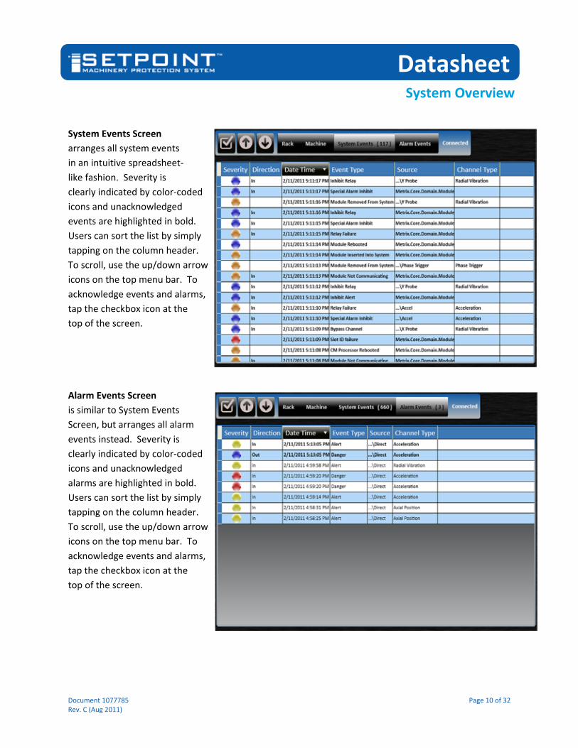
System Events Screen
arranges all system events
in an intuitive spreadsheet‐
like fashion. Severity is
clearly indicated by color‐coded
icons and unacknowledged
events are highlighted in bold.
Users can sort the list by simply
tapping on the column header.
To scroll, use the up/down arrow
icons on the top menu bar. To
acknowledge events and alarms,
tap the checkbox icon at the
top of the screen.
Alarm Events Screen
is similar to System Events
Screen, but arranges all alarm
events instead. Severity is
clearly indicated by color‐coded
icons and unacknowledged
alarms are highlighted in bold.
Users can sort the list by simply
tapping on the column header.
To scroll, use the up/down arrow
icons on the top menu bar. To
acknowledge events and alarms,
tap the checkbox icon at the
top of the screen.

Datasheet
System Overview
Document 1077785 Page 11 of 32 Rev. C (Aug 2011)
Specifications
Specifications provided are for rack chassis,
system power, and touchscreen display only.
For detailed specifications on each module type
and selected accessories, refer to the following
companion datasheets:
Components Datasheet
SAM 1077786 UMM 1077787 TMM 1077788 RCM and External Power Supplies 1078950 Weatherproof Housings 1078951 SETPOINT Software 1078952
All specifications are at +25C (+77° F) unless
otherwise noted.
Inputs
Number of Slots
Full Rack: 16
Half Rack: 8
Supported Module Types
Module Location Max Qty
RCM Slot 1 1
SAM Slot 2* 1*
UMM Slots 3‐16 14
TMM Slots 3‐16 14 * A second SAM may be installed in slot 3 if desired for redundant DCS communications. Availability of this feature is planned for 1Q2012.
Transducer Types
UMM cards accept most commercially available proximity probe, accelerometer, and velocity transducers. TMM cards accept 2‐, 3‐, and 4‐wire RTDs and Type J, K, T, and E thermocouples (both grounded
and ungrounded tip). Refer to the UMM and TMM datasheets 1077787 and 1077788 for a comprehensive list of compatible transducers.
Channels Vibration: up to 56 (14 UMM cards)
Temperature: up to 84 (14 TMM cards)
Phase/Speed: up to 6*
* Speed / phase channels are restricted to channel 4 of a UMM. A full‐size SETPOINT rack may have up to 6 (six) speed/phase channels and they must reside in slots 4‐9. A half‐size SETPOINT rack may have up to 5 (five) speed/phase channels and they must reside in slots 4‐8.
Discrete Rack Control
Four “dry contact” type connections are available via the RCM:
Alarm Reset (Acknowledge)*
Inhibit (Bypass)
Trip Multiply
Special Alarm Inhibit These can be invoked remotely by wiring suitable analog control signals. Refer to RCM datasheet 1078950 for details. * NOTE: The Alarm Reset (Acknowledge) function is also available as a local pushbutton on the RCM faceplate.
Digital Rack Control
Selected control (such as Trip Multiply, Alarm Adjust, Reset, Set date/time, etc.) of the rack, modules, and individual channels is available via the digital MODBUS interface on the System Access Module. Refer to the SAM datasheet 1077786 for details.

Datasheet
System Overview
Document 1077785 Page 12 of 32 Rev. C (Aug 2011)
Rack, Channel, and Module Configuration
Connection of SETPOINT software to the USB port on any UMM or TMM allows configuration of all modules in the rack. Future connectivity is planned to allow remote configuration of the rack over a secure control network via the 10/100 BASE‐T communications port on the SAM.* * Remote configuration capabilities planned for 1Q2012.
Number of Supplies
Accepts up to two +24 Vdc independent power sources
Allowable Wiring Sizes for Power
12 AWG to 16 AWG via removable plugs
Power Connector Style
Removable, with positive retention
Reverse Polarity Protection
Power inputs protected from continuous input polarity reversal.
Input Voltage
Nominal: +24 Vdc
Continuous: + 22 to +30 Vdc
Transient (< 1 sec) : +18 to + 36 Vdc
Ripple < 100mV pk to pk
Power Consumption
≤ 160W, <8A when input power voltage is 22 to 26 Vdc. NOTE: Assumes fully loaded 16‐position rack with display, redundant SAMs, all relays energized, all 4‐20 mA outputs at full scale, and maximum transducer power requirements.
Power Input Fuse Rating
10 A
Ground Select
System common tied to chassis ground (external jumper* installed)
System common isolated from chassis ground** (external jumper* removed)
*Jumper is accessible from the front of the rack and may be installed on either the P1 or P2 removable wiring connectors on the RCM.
** This configuration is commonly used for systems with IS barriers where a separate IS ground must be established.
Alarm Reset Alarm conditions can be reset (i.e., acknowledged) in any of four ways: 1. Via the local RESET
pushbutton on the faceplate of the RCM*
2. Via remote contact closure by shorting the RST and COM terminals together on the RCM*
3. Via the optional touchscreen display*
4. Via the MODBUS digital interface**
* Provides global (rack‐wide) reset / acknowledgement of all alarms. ** Provides per‐channel reset / acknowledgement of alarms.

Datasheet
System Overview
Document 1077785 Page 13 of 32 Rev. C (Aug 2011)
Buffered Transducer Outputs
Front Panel Channels*
Three, programmable** via touchscreen:
Connector A can select from any speed / phase channel in the rack.
Connector B can select from any UMM channel in the rack.
Connector C can select from any UMM channel in the rack. By default, it will select the corresponding pair (if applicable and if assigned in configuration) for the channel on connector B.
* Only Universal Monitoring Module (UMM) channels are available at buffered outputs. TMM (temperature) channels are not available. ** Functionality planned for 1Q2012 via no‐charge firmware update.
Connector Type
BNC female
Impedance
550 Ω
Short‐Circuit Protected
Yes
Signal Type
Raw (unfiltered, no integration) transducer signal in mV/engineering units* * The Metrix 2‐wire digital proximity transducer system provides a dynamic 4‐20 mA signal that is converted to a standard mV/mil signal inside the UMM.
UMM Channels
All 4 UMM channels are available concurrently at the RJ45 connector on the
UMM’s faceplate. A special RJ45‐to‐4‐BNC cable is available as an optional accessory (p/n 100431).
Connector Type
RJ45 receptacle
Impedance
550 Ω
Short‐Circuit Protected
Yes
Signal Type
Raw (unfiltered, no integration) transducer signal in mV/engineering units*
* The Metrix 2‐wire digital proximity transducer system provides a dynamic 4‐20 mA signal that is converted to a standard mV/mil signal inside the UMM.
RCM Channels
56* * Only Universal Monitoring Module (UMM) channels. TMM (temperature) channels are not provided.
Connector Qty / Type
Two Molex® Pico‐Clasp® 30‐pin receptacles, each with 28 buffered output channels.* * Buffered outputs are also available on each UMM via an RJ45 connector with all 4 channels, and on the optional rack faceplate via 3 programmable BNC‐type connectors.
Impedance
550 Ω
Short‐Circuit Protected
Yes
Signal Type
Raw (unfiltered, no integration) transducer signal in mV/engineering units*
* The Metrix 2‐wire digital proximity transducer system provides a dynamic 4‐20 mA signal that is converted to a standard mV/mil signal inside the UMM.

Datasheet
System Overview
Document 1077785 Page 14 of 32 Rev. C (Aug 2011)
Analog Outputs
Alarm Relays Four per monitor module. Each UMM and TMM provides four SPDT relays that can be programmed for individual channels or for logical voting among two or more channels. Refer to UMM and TMM datasheets for details.
Fault (NOT OK) Relay
One per rack, located on the RCM. Refer to RCM datasheet for additional details.
4‐20 mA One per channel for all UMM and TMM cards. Refer to UMM and TMM datasheets for additional details.
Digital Outputs
Modbus TCP/IP
10/100 BASE‐T connector on SAM provides channel values, channel status conditions, and a variety of other data. Refer to SAM datasheet for additional details.
Condition Monitoring
10/100/1000 BASE‐T connector on SAM provides full static and dynamic (waveform) data using an open, published protocol. Refer to SAM datasheet for additional details.
LEDs
OK Each TMM and UMM provides an OK LED indicating that no faults or NOT OK conditions are present within the module or any channel therein.
Each SAM provides an OK LED indicating that no faults are present within the module.
Each RCM provides an OK LED indicating rack‐wide status; when lit, no faults or NOT OK conditions exist in any module or channel.
Relays Each UMM and TMM provides 4 LEDs (one for each relay) indicating that the relay is being driven true (corresponding to the configured alarm logic for each relay)
Bypass Each UMM and TMM provides an LED indicating that one or more channels are in a BYPASS condition.
Comms Each SAM provides two LEDs for each of its Ethernet ports, indicating whether a connection is present and whether send/receive activity is occurring.
Each SAM provides a Trip Multiply LED, indicating whether Trip Multiply has been invoked for the entire rack or any channel in the rack.
Each SAM provides a DSP (display) LED, indicating whether a touchscreen display is detected.
Power The RCM provides individual status LEDs for both Power 1 and Power 2 connections. When lit, power is detected and is within specifications.

Datasheet
System Overview
Document 1077785 Page 15 of 32 Rev. C (Aug 2011)
Display
Size 8.4 inches (213 mm), measured diagonally
Resolution 1024 x 768 (XGA)
Aspect Ratio 4:3
Backlight Rated for 100,000 hours to ½ brightness.
Technology Active TFT
Touchscreen Type
Resistive
Color 32‐bit (True Color)
Environment and Area Classification Rating
Same as rack and all modules. Inclusion of touchscreen display does not de‐rate rack environmental or area classification specifications.
API 670 Compatible
Yes. All status conditions and channels are indicated continuously on a single screen, without scrolling or multiplexing.
Display Refresh
Channel values and statuses are updated on the display once per second.
Max. Racks per display
A maximum of one SETPOINT rack may be connected to each touchscreen display.
Available screen types
Machine‐at‐a‐glance (MAG)
All channel values and statuses displayed concurrently, arranged by user‐configured groups (typically train/machine/bearing)
Rack‐at‐a‐glance (RAG)
Similar to MAG screen, but organized by physical rack slot/channel assignments (useful for I&C maintenance personnel that prefer to view data in terms of slots/channels)
Alarm Events
Displays the 1000 most recent alarm events with date/time stamp, type (alert, danger, fault, etc.), whether entering or leaving condition, channel name, and other details. Data is presented in spreadsheet‐like tabular format that can be sorted by touching any column header.
System Events
Displays the 1000 most recent system events with date/time stamp, type (module removed, bypass invoked, etc.), whether entering or leaving condition, channel name, and other details. Data is presented in spreadsheet‐like tabular format that can be sorted by touching any column header.
Channel / Relay Detail
Tapping on any bargraph or relay indicator while in the MAG or RAG brings up an inset screen with additional details for the selected point.
Event List Size: 1000 events
Time/Date Stamp Resolution: 40 ms
Alarm List Size: 1000 alarms
Time/Date Stamp Resolution: 40 ms

Datasheet
System Overview
Document 1077785 Page 16 of 32 Rev. C (Aug 2011)
Environmental
Operating Temperature
‐20C to +65C
Storage Temperature
‐40C to +85C
Operating Temp. Ramp
Do not exceed 0.5C/minute
Storage Temp. Ramp
Do not exceed 10C/minute
Humidity 5% to 95%, non‐condensing
CE Mark Directive (pending)
ESD Contact: 6 kV*
Air: 8 kV * Criteria B
Radiated EMI Susceptibility
80 – 1000 MHz: 20 V/m*
1.4 – 2 GHz: 6 V/m*
2 – 2.7 GHz: 3 V/m* * Criteria A
Magnetic Field
30 A/m, Criteria A
EFT Burst 2 kV, Criteria B
EFT Surge (Signal Lines, Power Line)
2 kV line to ground, Criteria B
Conducted RFI (Signal Lines, Power Lines)
150 kHz to 80 MHz, Criteria A
Conducted RF Common Mode Immunity (Signal Lines, Power Lines)
15 Hz – 150 Hz: 10 V*
150 Hz – 1.5 kHz: 1V*
1.5 kHz – 150 kHz: 10 V* * Criteria A
Radiated EMI Emissions
30 dB µV/m @ 30 m, 30 MHz – 1000 MHz, Class A
Conducted Emission
60 dB µV/m @ 30 m, 0.5 MHz – 30 MHz, Class A
AC Power Voltage Dip Immunity
One‐half period, 30% reduction, Criteria B
AC Power Voltage Dip Interruption
250 periods, 95% reduction, Criteria B
DC Power Voltage Dip Immunity
10 ms, 60% reduction, Criteria B
DC Power Voltage Dip Interruption
30 ms, 100% reduction, Criteria B
Low Voltage Directive
Council Directive 2006/95/EC Low voltage using Metrix‐supplied power supply (rack ordering option –CC) or other Low Voltage Directive approved supply.
Hazardous Area Approvals (pending)
ATEX/IEC Ex – Zone 2
Ex nA [ic] IIC T4 @ ‐20C < Ta < +65C
USA/CanadaClass I, Div 2 / Zone 2
Class I, Div 1, Groups A‐D T4 @ ‐20C < Ta < +65C
Class I, Zone 2 AEx nA IIC T4 @ ‐20C < Ta < +65C
Physical
Dimensions See page 23
Weight Empty Rack Chassis*
Full‐size: 7.2 kg (15.9 lbs) Half‐size: 4.8 kg (10.6 lbs) * Includes 3” brackets, no faceplate, no display, no modules, no blank covers for unused module slots.
Lockable Faceplate w/o display
Full‐size: 1.5 kg (3.3 lbs) Half‐Size: 895 g (2 lbs)
Lockable Faceplate w/ display
Full‐size: 2.12 kg (4.7 lbs) Half‐size: 1.5 kg (3.3 lbs)
3” mounting bracket
190 g (6.5 oz)
Flush mounting bracket*
80 g (3 oz) * Used for bulkhead and flush mounting.
Blank Slot Cover Plate
48 g (1.7 oz)
Datasheet
System Overview
Document 1077785 Page 17 of 32 Rev. C (Aug 2011)
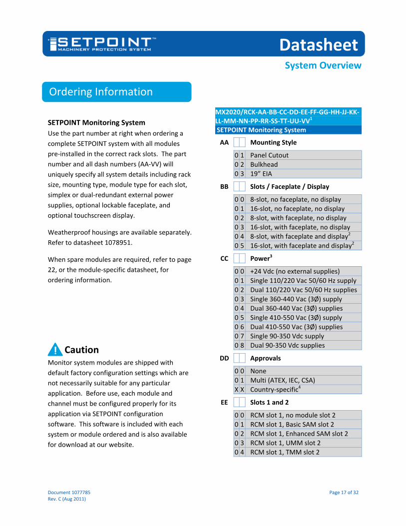
Ordering Information
SETPOINT Monitoring System
Use the part number at right when ordering a
complete SETPOINT system with all modules
pre‐installed in the correct rack slots. The part
number and all dash numbers (AA‐VV) will
uniquely specify all system details including rack
size, mounting type, module type for each slot,
simplex or dual‐redundant external power
supplies, optional lockable faceplate, and
optional touchscreen display.
Weatherproof housings are available separately.
Refer to datasheet 1078951.
When spare modules are required, refer to page
22, or the module‐specific datasheet, for
ordering information.
Caution Monitor system modules are shipped with
default factory configuration settings which are
not necessarily suitable for any particular
application. Before use, each module and
channel must be configured properly for its
application via SETPOINT configuration
software. This software is included with each
system or module ordered and is also available
for download at our website.
MX2020/RCK‐AA‐BB‐CC‐DD‐EE‐FF‐GG‐HH‐JJ‐KK‐LL‐MM‐NN‐PP‐RR‐SS‐TT‐UU‐VV1 SETPOINT Monitoring System
AA Mounting Style
0 1 Panel Cutout
0 2 Bulkhead
0 3 19” EIA
BB Slots / Faceplate / Display
0 0 8‐slot, no faceplate, no display
0 1 16‐slot, no faceplate, no display
0 2 8‐slot, with faceplate, no display
0 3 16‐slot, with faceplate, no display
0 4 8‐slot, with faceplate and display2
0 5 16‐slot, with faceplate and display2
CC Power3
0 0 +24 Vdc (no external supplies)
0 1 Single 110/220 Vac 50/60 Hz supply
0 2 Dual 110/220 Vac 50/60 Hz supplies
0 3 Single 360‐440 Vac (3Ø) supply
0 4 Dual 360‐440 Vac (3Ø) supplies
0 5 Single 410‐550 Vac (3Ø) supply
0 6 Dual 410‐550 Vac (3Ø) supplies
0 7 Single 90‐350 Vdc supply
0 8 Dual 90‐350 Vdc supplies
DD Approvals
0 0 None
0 1 Multi (ATEX, IEC, CSA)
X X Country‐specific4
EE Slots 1 and 2
0 0 RCM slot 1, no module slot 2
0 1 RCM slot 1, Basic SAM slot 2
0 2 RCM slot 1, Enhanced SAM slot 2
0 3 RCM slot 1, UMM slot 2
0 4 RCM slot 1, TMM slot 2
!

Datasheet
System Overview
Document 1077785 Page 18 of 32 Rev. C (Aug 2011)
FF Slot 3
0 0 No Module Installed
0 1 Basic SAM (bSAM)
0 2 Enhanced SAM (eSAM)
0 3 UMM
0 4 TMM
GG Slot 4
0 0 No Module Installed
0 3 UMM
0 4 TMM
HH Slot 5
0 0 No Module Installed
0 3 UMM
0 4 TMM
JJ Slot 6
0 0 No Module Installed
0 3 UMM
0 4 TMM
KK Slot 7
0 0 No Module Installed
0 3 UMM
0 4 TMM
LL Slot 8
0 0 No Module Installed
0 3 UMM
0 4 TMM
MM Slot 9
0 0 No Module Installed
0 3 UMM
0 4 TMM
NN Slot 10
0 0 No Module Installed
0 3 UMM
0 4 TMM
PP Slot 11
0 0 No Module Installed
0 3 UMM
0 4 TMM
RR Slot 12
0 0 No Module Installed
0 3 UMM
0 4 TMM
SS Slot 13
0 0 No Module Installed
0 3 UMM
0 4 TMM
TT Slot 14
0 0 No Module Installed
0 3 UMM
0 4 TMM
UU Slot 15
0 0 No Module Installed
0 3 UMM
0 4 TMM
VV Slot 16
0 0 No Module Installed
0 3 UMM
0 4 TMM
NOTES:
1. To prevent ambiguity, the letters I, O, and Q are not
used in Metrix part numbers.
2. When a touchscreen display is installed, an Enhanced
SAM must be selected for slot 2 (EE=02).
3. When dual external power supplies are required and
each will use a different voltage, order a system with a
simplex power supply for one of the required voltages.
Order the other external supply via part number
MX2020/EPS‐AA‐BB (refer to datasheet 1078950).
4. Country‐specific approvals can be quoted upon request.
Please consult the factory.

Datasheet
System Overview
Document 1077785 Page 19 of 32 Rev. C (Aug 2011)
Accessories
SAM‐to‐Display Cable
This cable is used when
connecting a rack’s
touchscreen display to
its associated Enhanced
SAM. Each touchscreen
ships by default with a
7.5” cable, allowing the
lockable faceplate and
display to mount
immediately in front of the rack. If the rack will
be located separately from the display, longer
versions are available, allowing up to 10 feet of
cable between the display and the SAM.
Identical male connectors are preinstalled at
each end, compatible with the female
connectors at the SAM and the touchscreen.
The connectors snap securely into place using
integral locking mechanisms.
100410‐AAAAA SAM‐to‐Touchscreen Cable
AAAAA Cable Length
0 0 7 5 0 7.5 inch (191 mm) length
1 2 0 0 0 10’ (3 m) length
External Power Supplies
Use the CC option when ordering
a single power supply with each
system, or when ordering
redundant power supplies
that will use the same
voltage. Use the part numbers
below when ordering a spare
power supply, or when ordering
the second power supply for redundant
configurations utilizing two different input
voltages.
100411* 110/220 VAC External Power Supply (spare)
100414* 360‐440 3Ø VAC External Power Supply (spare)
100416* 450‐550 3Ø VAC External Power Supply (spare)
100417** 90‐350 VDC External Power Supply (spare)
* Provided with following multiple approvals as standard:
CSA Class I, Division 2, Groups A‐D; Class I, Zone 2, Ex nC IIC T4
ATEX II 3G Eex nAC IIC T4
IEC/EN Class I, Zone 2, Eex nC II C T4 U
CE
** Provided with following multiple approvals as standard:
UL/c‐UL Recognized UL 1604 Class I, Division 2, Groups A‐D
ATEX II 3G Eex nAC IIC T4
CE

Datasheet
System Overview
Document 1077785 Page 20 of 32 Rev. C (Aug 2011)
Breakout Cable*
This cable is used when
connecting the
channels in a single
UMM to an external
device such as a portable
data collector with female
BNC jacks. When it is necessary to
simultaneously connect channels from multiple
UMMs to external instruments, use two or more
breakout cables. For ease‐of‐identification, each
BNC connector is numbered under a clear heat‐
shrink label, corresponding to each UMM
channel number. When longer cable runs are
required, simply purchase standard CAT5E cable
in the desired length and use an RJ45‐to‐RJ45
inline connector. Both are readily available from
a variety of electronics suppliers.
100431‐AA BNC breakout cable assembly – RJ45 (male) to four BNC (male)
AA Cable Length
1 0 10 foot (3 m) cable length
* NOTE: For systems with programmable BNC jacks on the
SETPOINT faceplate, this cable is not required unless simultaneous
connection of more than three (3) channels at a time to an
external instrument is necessary.
24 Vdc Power Cable
This 3‐conductor cable is
used to connect a bench
or desktop 24 Vdc power
supply to a SAM, UMM, or
TMM, allowing stand‐alone testing and/or
configuration of the module without the need to
insert it into a SETPOINT rack. One end of the
cable has a receptacle that mates to the
module’s backplane power connector. The
other end of the cable has 3 conductors (PWR,
COM, GND) for connection to a suitable 24 Vdc
power source.
100436‐AA 24Vdc SETPOINT Module Power Cable
AA Cable Length
0 6 6 foot (1.8 m) cable length
UMM Loop Test Harness
This cable assembly allows
complete loop testing of the
UMM when exercising the
built‐in self‐test features on
each card. It is the same
harness used during final test in
the factory manufacturing
process and allows the user to
verify signal inputs, 4‐20 mA outputs, relay
outputs, and transducer power outputs. The
UMM manual provides detailed guidance for
maintenance personnel on the use of this
harness and the accompanying UMM self‐test
procedure.
100434 UMM Loop Test Harness

Datasheet
System Overview
Document 1077785 Page 21 of 32 Rev. C (Aug 2011)
TMM Loop Test Harness
This cable assembly allows
complete loop testing of the
TMM when exercising the built‐in
self‐test features on each card. It
is the same harness used during
final test in the factory
manufacturing process and allows
the user to verify signal inputs, 4‐20 mA outputs,
relay outputs, and transducer power outputs.
The TMM manual provides detailed guidance for
maintenance personnel on the use of this
harness and the accompanying TMM self‐test
procedure.
100460 TMM Loop Test Harness
3” Rack Mounting Bracket
These brackets are sized to
recess the front of the rack
3” behind the face of the
bracket. All systems
ordered with a faceplate
(MX2020/RCK option AA =
02, 03, 04, or 05) include
two of these brackets,
allowing sufficient space
behind the rack’s faceplate to
recess all module wiring. Normally, the brackets
do not need to be ordered separately as they
are included with each system based on the
mounting option chosen.
Use the part number below only when replacing
lost or damaged brackets, or when retro‐fitting
a faceplate to a rack that is flush mounted. The
bracket is ambidextrous, and may be used on
the left or right side of the rack.
100375 SETPOINT 3” Rack Mounting Bracket
Flush Rack Mounting Bracket
These brackets are sized to align
the front of the rack with the
face of the bracket and are
intended only when mounting
the rack without a faceplate,* or
when bulkhead mounting.
Normally, the brackets do not
need to be ordered separately as
they are included with each
system based on the mounting
option chosen. Two of these brackets are
supplied with each system using bulkhead
mounting. Two are also supplied with all
systems ordered without a faceplate, regardless
of mounting option. The brackets mount on the
rear of the rack when bulkhead mounting and
on the front of the rack when flush mounting in
a panel cutout or on 19” EIA rails.
Use the part number below only when replacing
lost or damaged brackets, or when changing to
bulkhead mounting. The bracket is
ambidextrous, and may be used on the left,
right, front, or rear of the rack.
100384 SETPOINT Flush Rack Mounting Bracket
* When observing minimum bend radius for cables, wiring will
typically protrude 2 inches (50 mm) beyond the face of the rack.
When the wiring should not protrude beyond the bracket face, use
3” brackets instead (p/n 100375).

Datasheet
System Overview
Document 1077785 Page 22 of 32 Rev. C (Aug 2011)
Spares
Manuals and Software
A complete set of
SETPOINT manuals
and configuration
software is supplied
on USB memory stick
at no extra charge
with each system. As languages in addition to
English become available, they will also be
included on the memory stick.
The most recent version of manuals and
software can also be downloaded directly from
our website.
Manuals are published electronically in Adobe®
PDF* format and may be printed and freely
distributed.
* NOTE: Adobe Reader is required and can be downloaded free‐
of‐charge from www.adobe.com.
MX2020/CSW‐AA SETPOINT Manual and Configuration Software
AA Format
0 1 USB Memory Stick
Rack Connection Module (RCM)
MX2020/RCM‐AA Rack Connection Module (spare)
AA Agency Approvals
0 5 Multiple Approvals (CSA, IEC, ATEX)
System Access Module (SAM)
MX2020/SAM‐AA‐BB‐CC System Access Module (spare)
AA Communications Protocol
0 1 Modbus® TCP/IP
BB Type
0 0 bSAM (basic SAM)
0 1
eSAM (enhanced SAM with additional processor board to support dynamic data capture and optional touchscreen display)
CC Agency Approvals
0 5 Multiple Approvals (CSA, IEC, ATEX)
Universal Monitoring Module (UMM)
MX2020/UMM‐AA Universal Monitoring Module (spare)
AA Agency Approvals
0 5 Multiple Approvals (CSA, IEC, ATEX)
Temperature Monitoring Module (TMM)
MX2020/TMM‐AA Temperature Monitoring Module (spare)
AA Agency Approvals
0 5 Multiple Approvals (CSA, IEC, ATEX)
Blank Slot Faceplates
All unused slots in system racks ship
with blank faceplates installed. To
replace a lost or damaged faceplate,
order 1 faceplate and 5 EMI clips.
100367 (blank faceplate) 100462 (EMI clips) SETPOINT blank faceplate for unused slots

Datasheet
System Overview
Document 1077785 Page 23 of 32 Rev. C (Aug 2011)
Wiring and Outline Diagrams
NOTES:
1. For flush‐mount brackets, L=0. Captive screws will protrude
by amount shown and total system depth becomes M+P.
2. Faceplate adds 0.39” (10 mm) to total system depth.
3. BNC connectors protrude 0.62” (16 mm) and keylock
protrudes 0.71” (18 mm) beyond front of faceplate.
Dim. Full Rack (16P) Half Rack (8P)
A 6U / 10.47” (266 mm) Same as 16P
B 5.16” (131 mm) Same as 16P
C 7.50” (190 mm) Same as 16P
D 2.82” (72 mm) Same as 16P
E 6.80” (173 mm) Same as 16P
F 19.00” (483 mm) 11.00” (279 mm)
G 18.31” (465 mm) 10.31” (262 mm)
H 16.32” (415 mm) 8.32” (211 mm)
J 9.06” (230 mm) Same as 16P
K 7.50” (190 mm) Same as 16P
L 1,2,3 2.95” (75 mm) Same as 16P
M 8.56” (217 mm) Same as 16P
N 16.50” (419 mm) 8.50” (210 mm)
P 0.32” (8 mm) Same as 16P
R 9.06” (230 mm) Same as 16P

Datasheet
System Overview
Document 1077785 Page 24 of 32 Rev. C (Aug 2011)
Bulkhead Mounting Style
Rear of rack mounts flush to wall or panel using
flush‐mount brackets. Front of rack may use
optional faceplate with or without touchscreen
display (for clarity, faceplate and display not
shown here). When faceplate is installed it is
supported on front of rack using two 3” rack
brackets (shown). Faceplate is hinged to allow
easy maintenance access.
Panel Cutout Mounting Style
Rack mounts into rectangular cutout and is
supported by brackets. Two 3” brackets are
shown here, allowing all wiring to be recessed
behind the cutout. Optional lockable faceplate
and touchscreen display (not shown) may be
installed over front to conceal opening.
Faceplate is hinged to allow easy maintenance
access.

Datasheet
System Overview
Document 1077785 Page 25 of 32 Rev. C (Aug 2011)
19” EIA Mounting Style (Recessed)
Rack mounts onto standard EIA 19” rails and is
supported by two 3” brackets, allowing all wiring
to be recessed. Optional lockable faceplate and
touchscreen display (not shown) may be
installed over front to conceal opening.
Faceplate is hinged to allow easy maintenance
access.
19” EIA Mounting Style (Flush)
Rack mounts onto standard EIA 19” rails and is
supported by two flush brackets. Wiring is not
recessed and assumes that the optional
faceplate and display will not be installed.

Datasheet
System Overview
Document 1077785 Page 26 of 32 Rev. C (Aug 2011)
Modbus Client 1
Ethernet
Switch
Modbus Client 2
Modbus Client 3
Modbus Client 4
Modbus Client 5
Modbus Client 6
SETPOINT™ System Rack
Master Clock
OSIsoft
PI System®
Software
Other Historian
Software
Other Condition
Monitoring
Software
SETPOINT
Config SW
Ethernet
Switch
SETPOINT open dynamic data protocol
Optional 8.4” touchscreen
display on rack faceplate
Protocols:
SETPOINT configuration Modbus TCP/IP NTP

Datasheet
System Overview
Document 1077785 Page 27 of 32 Rev. C (Aug 2011)
RACK DISCRETE INPUTS (CLOSED = ACTIVE)
TYPICAL EXTERNAL DIN‐RAIL POWER SUPPLY
INPUT VOLTAGE
1.110/220 VAC
2.400 VAC (3‐PH)
3.500 VAC (3‐PH)
4.90‐350 VDC
REM
OVABLE EXTERNAL JUMPER
TYING
SYSTEM
COMMON TO CHASSIS GROUND
ALARM RESET
(ACKNOWLEDGE)
INHIBIT (BYPASS)
TRIP MULTIPLY
SPECIAL ALARM INHIBIT
SYSTEM FAULT (NOT OK) RELAY
(NC SHORTED TO ARM WHEN FAULT CONDITION PRESENT)
TO PANEL
ANNUNCIATORS,
PLCs, DCSs, AND
OTHER SYSTEMS
ACCEPTING RELAY
CONTACTS
PATCH PANELS,
MULTI‐CHANNEL DATA
ACQUISITION INSTRUMENTS,
ETC.
TO INDEPENDENT +24VDC
POWER SOURCE (WHEN
REDUNDANCY REQ’D)
OUTPUT VOLTAGE
+24 VDC

Datasheet
System Overview
Document 1077785 Page 28 of 32 Rev. C (Aug 2011)
DRIVER
EXTENSION
CABLE
PROXIMITY PROBE
(Observing shaft radial
vibration, axial
position, or a once‐per‐
turn phase trigger
signal)
ACCELEROMETER
PIEZO‐VELOCITY
SENSOR
MOVING‐COIL
VELOCITY SENSOR
STRIP CHART
RECORDERS, PLCs,
DCSs, OR OTHER
SYSTEMS ACCEPTING
4‐20 mA SIGNALS
MACHINE CONTROL SYSTEMS,
SHUTDOWN SYSTEMS, MOTOR
STARTERS, PANEL ANNUNCIATORS,
OR OTHER SYSTEMS ACCEPTING
RELAY CONTACTS

Datasheet
System Overview
Document 1077785 Page 29 of 32 Rev. C (Aug 2011)
TYPICAL
4‐WIRE RTD
STRIP CHART RECORDERS, PLCs, DCSs,
OR OTHER SYSTEMS ACCEPTING 4‐20
mA SIGNALS
MACHINE CONTROL SYSTEMS,
SHUTDOWN SYSTEMS, MOTOR
STARTERS, PANEL ANNUNCIATORS,
OR OTHER SYSTEMS ACCEPTING
RELAY CONTACTS
TYPICAL
3‐WIRE RTD
TYPICAL
2‐WIRE RTD
TYPICAL UNGROUNDED
THERMOCOUPLE TIP
TYPICAL GROUNDED
THERMOCOUPLE TIP
B C
B C
S

Datasheet
System Overview
Document 1077785 Page 30 of 32 Rev. C (Aug 2011)
Up to 32 GB of onboard “flight
recorder” data capture and storage
on removable SD card. Ensures data
is available even in the event Gigabit
communications with the SAM are
lost or interrupted.
10/100/1000 BASE‐T Gigabit
communications using an industry‐
first open protocol for easy access by
process historian and condition
monitoring software. Native
connectivity to OSIsoft’s PI® System.
Optional 8.4” color touchscreen
display interface. Allows display to be
located anywhere within 3 m (10
feet) of SETPOINT rack.
Captive thumbscrew for securing SAM
in SETPOINT rack slot.
Industry‐standard MODBUS®
TCP/IP communications via 10/100
BASE‐T for integration with plant
and machinery control systems,
SCADA systems, and other control
and automation platforms.
Supports NTP for clock
synchronization. Also allows
remote access to rack by SETPOINT
configuration software. (Future)
Captive thumbscrew for securing SAM
in SETPOINT rack slot.
MODULE OK, TRIP MULTIPLY, and
DISPLAY COMMUNICATIONS OK
status LEDs.
DCS Link Present LED
DCS Link Activity LED
DAC Link Activity LED
DAC Link Present LED

Datasheet
System Overview
Document 1077785 Page 31 of 32 Rev. C (Aug 2011)
Captive thumbscrew for securing RCM
in SETPOINT rack slot. Discrete inputs for invoking rack‐
wide functions:
‐ Alarm Reset (Acknowledge)
‐ Rack Inhibit (Bypass)
‐ Trip Multiply
‐ Special Alarm Inhibit
Dry contact or TTL‐compatible active
when pulled to common or TTL zero.
System Fault (i.e. NOT OK) Relay.
Local Alarm Reset (Acknowledge)
Pushbutton. Performs same function
as when RST and COM discrete input
terminals are shorted. SYSTEM OK, Power 1, and Power 2
LEDs. SYSTEM OK LED is green when
no faults are present. P1 is green
when supply 1 detected and within
specs. P2 is green when supply 2
detected and within specs.Primary/Secondary +24 Vdc (nominal)
power source connections. Power 2 is
on top, Power 1 is on bottom (labels
are visible behind connectors).
Buffered transducer outputs for all
rack UMM channels (up to 56).
Intended primarily for wiring to
permanent patch panels or multi‐
channel data acquisition instruments.
Captive thumbscrew for securing RCM
in SETPOINT rack slot.

Datasheet
System Overview
Document 1077785 Page 32 of 32 Rev. C (Aug 2011)
Input connections for all module
channels. Connectors are
removable to facilitate ease of
wiring.
4‐20 mA proportional analog
output connections for all
channels. Connectors are
removable to facilitate ease of
wiring.
Mechanical relay output
connections for relays 1‐4.
Connector is removable to
facilitate ease of wiring.
Captive thumbscrews for securing
modules in SETPOINT rack slots.
Captive thumbscrews for securing
modules in SETPOINT rack slots.
RJ45 receptacle with buffered
output signals for channels 1‐4
on individual pins.
OK, BYPASS, and Relay LEDs
Metrix Instrument Company
8824 Fallbrook Drive
Houston, TX 77064 USA
(281) 940‐1802
www.metrixsetpoint.com
Trademarks used herein are the property of their
respective owners.
Data and specifications subject to change without
notice.
© 2011 Metrix Instrument Company, L.P.
Mini‐B USB receptacles for
connection to SETPOINT
configuration software via USB
cable.


![[Metrix]버즈리서치소개자료 (3)](https://img.pdfslide.tips/doc/110x75/5596e3aa1a28ab9f2a8b45d5/metrix-3.jpg)


![Notice Oscilloscope METRIX-OX712D[1]](https://img.pdfslide.tips/doc/110x75/543e362fb1af9f272b8b4825/notice-oscilloscope-metrix-ox712d1.jpg)