Embed Size (px)
Citation preview

Maserati Technical Bulletin
© 2016 Maserati North America, Inc. AfterSales www.maseratiusa.com
All rights reserved. Reproduction or translation in whole or in part is not permitted without authorization from the publisher. Printed in USA
Date: November 29th, 2016 Bulletin No. MAS001052 – Rear Differential Inspection_US Recall Campaign ‐ 328 Supersedes: N/A
Model: Quattroporte (M156) and Ghibli (M157) Model Year: 2017 Subject: Vehicle Safety Recall Campaign 328 – Rear Differential Inspection
PERFORM THE PROCEDURE OUTLINED IN THIS TECHNICAL BULLETIN ON ALL AFFECTED NEW VEHICLES BEFORE CUSTOMER DELIVERY OR FOR VEHICLES ALREADY SOLD AND DELIVERED THE NEXT TIME THE VEHICLE IS IN THE SHOP FOR MAINTENANCE OR REPAIRS. Maserati dealers must ensure recalls are completed after having been notified by Maserati North America, Inc. (MNA) that a safety-related defect or noncompliance exists in any motor vehicle or item of replacement equipment in the dealer’s possession at the time of notification. In MNA's case, this notification would typically be made by the issuance of a recall notification in the form of a Technical Bulletin. Under the National Traffic and Motor Vehicle Safety Act of 1966, as amended, if a recall campaign is announced by MNA, dealers must ensure that all recalls on new vehicles and new items of replacement equipment are completed BEFORE delivery to the consumer. This means that dealers may not legally deliver new motor vehicles or new items of replacement equipment to consumers with an open recall. The Safety Act also prohibits dealers from selling or leasing the motor vehicle or item of replacement equipment, unless and until the open recall has been completed BEFORE delivery. This also pertains to vehicles in the Certified Pre-Owned program, and to items of replacement equipment. Finally, MNA dealers should not sell or use parts that have been recalled by MNA. Please follow the specific instructions provided by MNA on the return or disposition of any parts.
MASERATI SAFETY RECALL BULLETIN
2 MAS001052_Recall_328_Rear_Differential_Inspection
Description of Vehicle Safety Recall 328
Maserati S.p.A. and MNA have determined that the above described vehicles were manufactured with a rear differential unit pinion nut that was not torqued correctly. The function of the pinion nut is to provide the axial force required for proper location of the pinion within the differential unit bearing assemblies. A loose pinion nut will result in a reduction or total loss of axial force, as well as, insufficient orientation of the pinion itself. A loose pinion nut will potentially have an adverse effect on noise, vibration and harshness (NVH) performance, reduced gear, and bearing life, and can cause a differential fluid leak at the pinion seal. In the most severe cases of a loose pinion nut, axial loads could force the pinion into a differential gear binding condition, which can result in blocking the rotation of the ring gear, and potentially locking the rear wheels, thereby increasing the risk of a vehicle crash.
Which Vehicles Are Affected
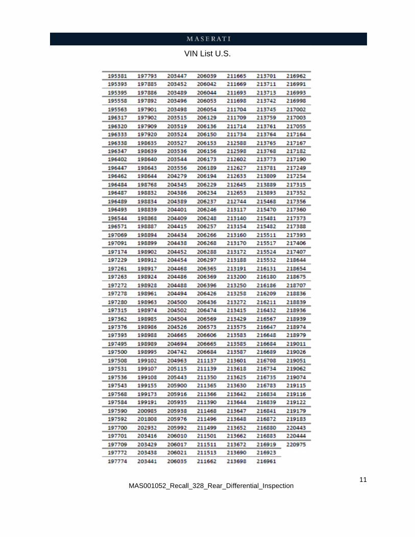
Please refer to ModisCS+ and the attached VIN list at the end of this bulletin for the affected vehicles in the U.S.
Vehicle Remedy Information
1. Check that the vehicle is included in this Recall campaign, and that this repair has not been previously performed.
2. Inspect the rear differential pinion nut torque. If a replacement differential is needed, see attachment “A” at the end of this bulletin.
3. The recall procedure is now complete.
This repair procedure will be performed free of charge to the customer.
Parts Needed For The Recall
For this Recall campaign, the rear differential P/N: 670039125 (if needed), must be ordered from the Maserati Parts Department.

1. D
2. S
3. Ds
4. D
5. L
6. R 0
Drive the ve
Set the park
Disengage tection 03.0
Disconnect
Lift the vehic
Remove the01.81.004 –a. Remove
b. Loosen
c. Remove
MAS0010
OP
hicle on to
king brake t
the gearbo02.018 – 02
the battery
cle.
e r/s and l/s – 00 and 01e the space
the exhaus
Fige the vacum
052_Recall_3
ERATIN
a lift.
o lock the r
ox parking 2 of the Wo
(08.20.001
exhaust ta.81.005 – 0
er bar (Fig.2
st clamps (N
g.3 me hose fro
328_Rear_Dif
G PROC
rear wheels
lock releasorkshop Ma
Fig.1
1 – 02 of the
ailpipes as s00 of the W2)
Fig.2
Num.1, in F
om the exha
fferential_Ins
CEDURE
s.
se by pullinanual and be
e Worksho
shown beloWorkshop Ma
Fig.3)
aust change
pection
E
ng the cabelow in Fig
p Manual).
ow and in seanual.
Fig.4 e-over valv
ble as show.1.
ection
ve (Fig.4)
3
wn in
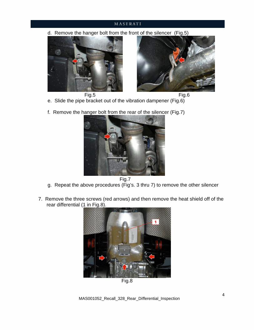
7. R r
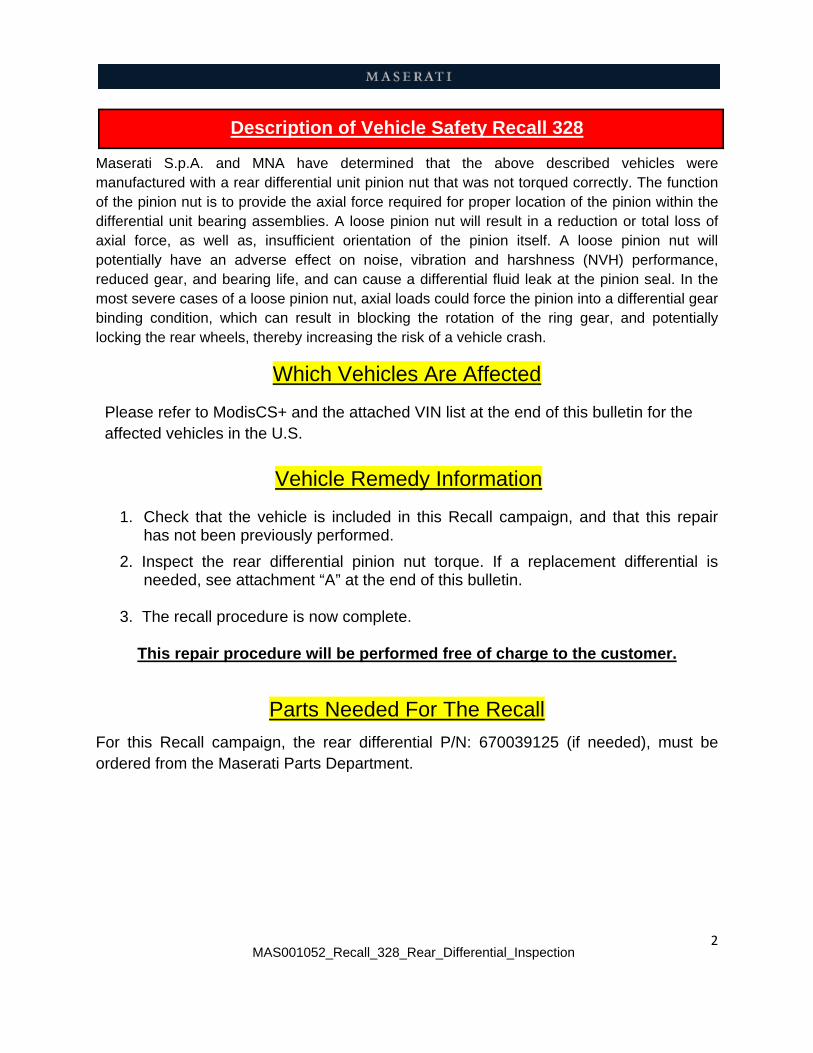
d. Remove
e. Slide th f. Remove
g. Repeat
Remove therear differen
MAS0010
e the hange
Fig.5e pipe brac
e the hange
the above
e three scrential (1 in F
052_Recall_3
er bolt from
5 cket out of t
r bolt from
procedures
ews (red arrig.8).
328_Rear_Dif
the front o
the vibration
the rear of
Fig.7 s (Fig’s. 3 th
rows) and t
Fig.8
fferential_Ins
of the silenc
n dampene
the silence
hru 7) to re
hen remove
pection
cer (Fig.5)
Fig.6 er (Fig.6)
er (Fig.7)
emove the o
e the heat s
other silenc
shield off o
4
cer
f the
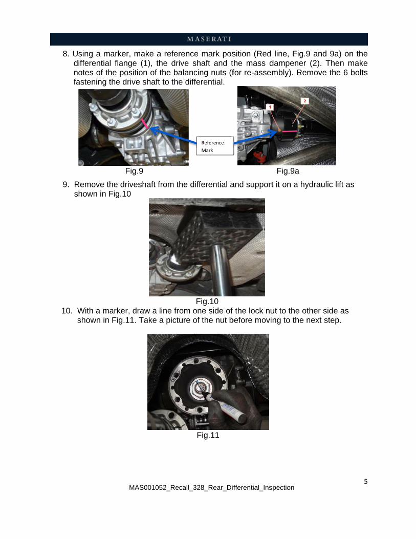
8. U d n fa
9. R s
10. W s
sing a marifferential fotes of theastening the
Remove thehown in Fig
With a marshown in F
MAS0010
rker, make flange (1), position ofe drive shaf
Fig.9
e driveshaft g.10
ker, draw aig.11. Take
052_Recall_3
a referencethe drive sf the balancft to the diff
from the d
a line from oe a picture o
328_Rear_Dif
e mark posshaft and tcing nuts (fferential.
ifferential a
Fig.10 one side of of the nut b
Fig.11
Reference
Mark
fferential_Ins
sition (Red he mass dfor re-assem
and support
the lock nubefore movi
pection
line, Fig.9 dampener (mbly). Rem
Fig.9a
t it on a hyd
ut to the othng to the ne
and 9a) on(2). Then m
move the 6
draulic lift a
her side as ext step.
5
n the make bolts
s

6 MAS001052_Recall_328_Rear_Differential_Inspection
11. With a calibrated torque wrench, tighten the lock nut to 245 Nm. (Fig.12) NOTE: Make sure the axles / wheels do not turn during this stage.
Fig.12
12. Perform a visual inspection of the nut to make sure it has not moved (Fig.13). Compare it with the picture taken in step 10. If there was any movement of the nut, the differential must be replaced. Refer to section 3.21.001 – 00 of the Workshop Manual and attachment “A” in this bulletin.
Fig.13
NOTE: Only perform step 13 if the nut moved and the differential has to be replaced.
13. Perform a visual inspection of the drive shaft cover to make sure there are no bumps or protrusions that may alter the smoothness of the cover (Fig.14).
If any bumps or protrusions are found, the drive shaft must be replaced. If replacing the drive shaft, refer to section 3.30.001 of the Workshop Manual.
Fig.14
14.
Complet
C W D C O O O
3 C
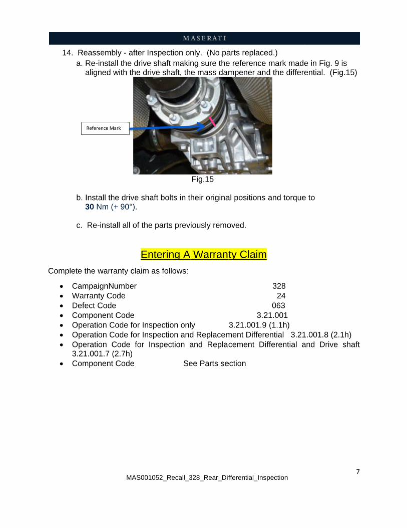
Reassemba. Re-insta aligned w
b. Install th 30 Nm (+ c. Re-insta
te the warra
CampaignNWarranty CoDefect CodeComponent Operation COperation COperation C
.21.001.7 (Component
Reference M
MAS0010
bly - after Inall the drive with the driv
he drive sha+ 90°).
all all of the
En
anty claim a
umber ode e Code
Code for InsCode for InsCode for In2.7h) Code
ark
052_Recall_3
nspection oshaft makive shaft, th
aft bolts in t
parts prev
ntering A
as follows:
spection onlspection andnspection a
Se
328_Rear_Dif
nly. (No pang sure thee mass dam
Fig.15
heir origina
iously remo
Warrant
ly d Replacemand Replac
ee Parts se
fferential_Ins
arts replacee reference mpener and
al positions
oved.
ty Claim
3.23.21.001.9
ment Differecement Dif
ection
pection
ed.) mark made
d the differe
and torque
328 24 063
21.001 (1.1h) ential 3.21fferential a
e in Fig. 9 iential. (Fig
e to
1.001.8 (2.1and Drive
7
s g.15)
1h) shaft
8 MAS001052_Recall_328_Rear_Differential_Inspection
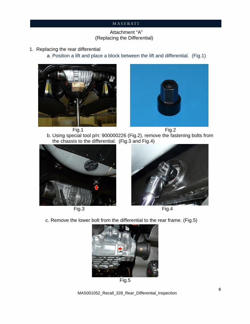
Attachment “A” (Replacing the Differential)
1. Replacing the rear differential a. Position a lift and place a block between the lift and differential. (Fig.1)
Fig.1 Fig.2 b. Using special tool p/n: 900000226 (Fig.2), remove the fastening bolts from the chassis to the differential. (Fig.3 and Fig.4)
Fig.3 Fig.4 c. Remove the lower bolt from the differential to the rear frame. (Fig.5)
Fig.5
9 MAS001052_Recall_328_Rear_Differential_Inspection
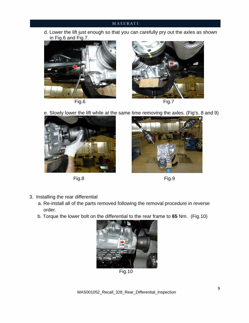
d. Lower the lift just enough so that you can carefully pry out the axles as shown in Fig.6 and Fig.7.
Fig.6 Fig.7 e. Slowly lower the lift while at the same time removing the axles. (Fig’s. 8 and 9)
Fig.8 Fig.9
3. Installing the rear differential a. Re-install all of the parts removed following the removal procedure in reverse order. b. Torque the lower bolt on the differential to the rear frame to 65 Nm. (Fig.10)
Fig.10

c. T c
d
Torque the rhassis to 1
. Place the made dur differentia
e. Install th 30 Nm (+
c. Re-instad. After roae. To bala Manual
MAS0010
rear fasteni90 Nm.
Fig.11
drive shaftring removaal (Num. 1 i
Fig.13
he drive sha+ 90°). (Fig
all rest of thad testing, nce the driv.
052_Recall_3
ng bolts (F
t in the diffeal (Fig.13 ann Fig.13a)
aft bolts in tg.14)
he parts preif any vibrave shaft, re
328_Rear_Dif
ig.11 and F
erential flannd 13a) aloand the ma
heir origina
Fig.14
eviously remations are oeffer to Sect
Reference
Mark
fferential_Ins
Fig.12) betw
nge and aligong with theass dampen
al positions
4
moved. bserved, bation 3.30.00
pection
ween the di
Fig.12
gn the refere mark on tner. (Num.2
Fig.13a
and torque
alance the 01-35 of the
fferential an
rence markshe new 2 in Fig.13a
e to
drive shafte Workshop
10
nd
s
a)
. p
MAS0010052_Recall_3
VIN
328_Rear_Dif
N List U.S.
fferential_Inspection
11