Embed Size (px)
Citation preview

MANUEL
D’UTILISATION
ET D’INSTALLATION
FR / EN / DE / NL / ESP
Pompe à chaleur Vesuvio-Inverter pour piscine


1
Résumé
I. Application ............................................................................................... 2
II. Informations générales ............................................................................. 2
III. Caractéristiques techniques ...................................................................... 3
IV. Dimensions .............................................................................................. 4
V. Instructions d’installation ......................................................................... 5
VI. Instruction d’utilisation ............................................................................ 8
VII. Test de l’appareil ................................................................................... 10
VIII Précautions ............................................................................................ 11
IX Entretien et hivernage .............................................................................. 12
X Guide de dépannages pour les pannes les plus courantes.......................... 13
XI Annexe 1: Schéma de câblage pour le contrôle externe (Optionel) ......... 15

2
Nous vous remercions d’avoir choisi notre pompe à chaleur et d’avoir placé
votre confiance dans notre marque.
Afin de vous permettre d’obtenir un maximum de satisfaction, nous vous
recommandons vivement de lire attentivement ce guide au préalable et de
respecter strictement les indications fournies afin de s’assurer de la sécurité
maximale des installateurs et des utilisateurs et d’éviter tout risque de
dégradation de l’appareil.
I. Application
1- Se référer aux caractéristiques techniques présentées dans ce guide de
façon à vous assurer du bon dimensionnement de votre pompe à chaleur.
2- Régler la température de l’eau de la piscine de manière efficace et
économique afin de bénéficier d’un maximum de de confort et de plaisir.
II. Informations générales
1- Echangeur titane
2- Affichage et gestion précise de la température de la température de l’eau
3- Protection contre les hautes et basses pressions du circuit frigoriphique
4- Protection automatique contre les températures trop basses.
5- Protection base température via dégivrage automatique
6- Compresseur Inverter
7- Installation et utilisation simple

3
III. Caractéristiques techniques
Model VESIN08N VESIN10N VESIN13N VESIN17N VESIN21N
Volume de la piscine appliqué (m3) 20~40 30~50 40~70 55-85 70-100
Plage de température de
fonctionnement (℃)
0~43
Performance Condition: Air 26°C, Water 26°C, Humidity 80%
Puissance calorifique (kW) 8.0 9.2 12.5 16.5 20.5
C.O.P 10.8~5.6 11.2~5.5 12.0~5.6 11.8~5.5 12.0~5.6
C.O.P à 50% de capacité 8.2 8.6 9.5 9.1 9.2
Performance Condition: Air 15°C, Water 26°C, Humidity 70%
Puissance calorifique (kW) 6.0 7.0 9.0 11.5 14.0
C.O.P 6.7~3.9 6.6 - 3.8 6.7 - 3.9 6.7 - 3.8 6.7 - 3.9
C.O.P à 50% de capacité 6.1 5.8 6.0 6.2 5.9
Puissance d’entrée nominale (kW)
air de 15°C
0.19 - 1.3 0.21 - 1.7 0.3 - 2.3 0.36 - 2.9 0.45 - 3.7
Courant d’entrée nominal (A)
air de 15°C
0.83 - 5.6 0.91 - 7.4 1.3 - 10 1.6 - 12.6 1.96 - 16.1
Courant d’entrée maximum (A) 7.5 9.0 11.0 15.0 18.5
Alimentation électrique 220 - 240V/1 Ph/50Hz
Débit d’eau minimale (m³/h) 2~4 3~4 4~6 6~8 8~10
Niveau de pression sonore à 10m
dB(A)
20.5~29.2 21.3~30 21.5~30.2 24.8~34.1 26.2~34.9
Connection hydraulique (mm) 50
Dimension LxWxH (mm) 864×349×648 864×349×648 864×349×648 954×349×648 954×349×748
Poids net (kg) 46 47 49 60 63
Remarques:
1- Ce produit fonctionne à des températures d’air comprises entre 0°C et +43°C, l’efficacité ne sera pas
garantie en dehors de cette plage. Merci de prendre en considération le fait que les performances et les
paramètres de votre pompe à chaleur pour piscine vont varier en fonction des différentes conditions
d’utilisation.

4
2- Ces paramètres de référence peuvent faire l’objet de corrections régulières au gré des évolutions produit
et améliorations techniques et ce sans préavis. Pour plus d’informations, merci de vous référer au nom
du modèle inscrit sur la plaque.
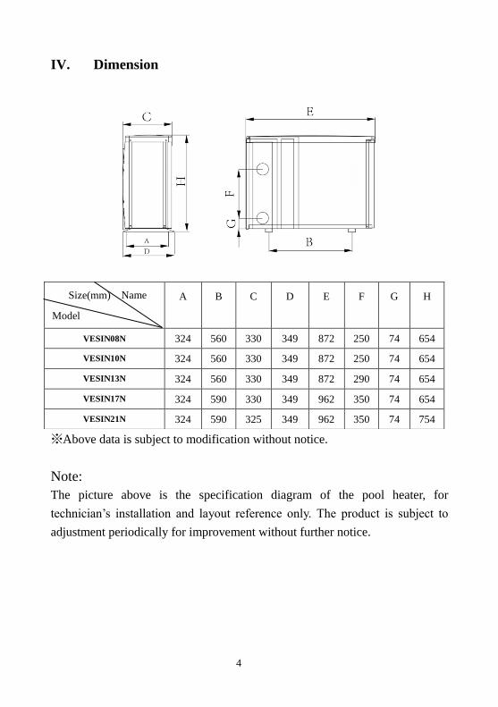
IV. Dimensions
*Ces données peuvent être amenées à évoluer sans préavis.
Remarque :
Le schéma ci-dessus de la pompe à chaleur sert de référence pour la mise en place et l’installation par le
technicien. Le produit peut être amené à évoluer de façon régulière et ce sans préavis.
A B C D E F G H
VESIN08N 324 560 330 349 872 250 74 654
VESIN10N 324 560 330 349 872 250 74 654
VESIN13N 324 560 330 349 872 290 74 654
VESIN17N 324 590 330 349 962 350 74 654
VESIN21N 324 590 325 349 962 350 74 754
Lettre Dimensions
(mm)
Modèle

5
V. Instructions d’installation
1. Schéma des connexions hydrauliques
(Remarque:Ce schéma est juste un support de référence et le circuit hydraulique représenté est simplement une base)
2. Schéma des connexions électriques
Remarques:1) Raccordement filaire, pas de connecteur
2) La pompe à chaleur doit bien être reliée à la terre.
Pour Alimentation de puissance: 230V 50Hz

6
Options pour dispositifs de protection et spécifications du câble
※Les données fournies ci-dessus peuvent être amenées à évoluer.
Remarque: Les données ci-dessus correspondent à un cordon d’alimentation ≤ 10 m. Si le cordon est﹥à 10 m,
la section de câble doit être augmentée. Ce câble peut avoir une longueur maximale de 50m.
3. Conditions préalables requises
La pompe à chaleur doit être installée par des professionnels. Les utilisateurs
ne sont pas qualifiés pour l’installer sous peine d’endommager l’appareil et de
mettre en péril leur propre sécurité.
A. Tuyauterie
1) Les raccords de l’eau entrée et sortie ne peuvent pas supporter le poids de
tuyaux souples. La pompe à chaleur doit être raccordée avec des tuyaux
rigidess !
2) Afin de garantir l’efficacité du chauffage, la longueur de tuyau doit être
≤10m entre la piscine et la pompe à chaleur.
MODEL VESIN08N VESIN10N VESIN13N VESIN17N VESIN21N
Interrup-teur
Courant A 9.0 11.0 13.5 18.0 22.0
Différentiel
mA 30 30 30 30 30
Fusible A 9.0 11.0 13.5 18.0 22.0
Câble d’alimentation (mm2) 3×1.5 3×2.5 3×2.5 3×2.5 3×4
Câble de signal (mm2) 3×0.5 3×0.5 3×0.5 3×0.5 3×0.5

7
B. Instructions d’installation
1) Emplacement et dimensions
La pompe à chaleur doit être installée dans une zone ventilée
2) La carcasse doit être fixée avec des écrous M10 à une base en béton ou avec
des équerres. La fondation en béton doit être solide et stable, les équerres
doivent pouvoir avoir une protection antirouille.
3) Ne pas obstruer les ventilations, l’air entrant et sortant doit pouvoir circuler
librement, et garder un espace libre d’au moins 50cm autour de l’appareil, à
défaut l’efficacité de la machine se verrait amoindrie voire stoppée.
4) L’appareil nécessite l’utilisation d’une pompe de filtration annexe (fournie
par l’utilisateur). Pour le débit recommandé de la pompe se référer aux
paramètres techniques. Hauteur de refoulement maxi ≥10m;
5) Quand l’appareil est en fonctionnement il y aura un dégagement de
condensation par le bas, il est important d’en tenir compte. Merci de tenir la
sortie vidange (accessoire) dans le trou et le clipser comme il faut, puis
connecter un tuyau pour dégager la condensation à l’extérieur.
* Distance minimal
Filtre
Traitement d’eau
By-pass

8
C.Câblage
1) Le câblage doit être fait par un technicien professionnel conformément au
schéma fourni
2) Effectuer la mise à la terre de la machine.
3) Connecter à l’alimentation qui convient, le voltage doit correspondre au
voltage nominal des produits
4) Installer une protection de fuite à la terre en accord avec la législation
pour le raccordement (courant détectant des fuites ≤ 30mA).
5) La mise en place du câble d’alimentation et du câble d’interface doit être
fait selon les normes et ne doit pas dépendre l’un de l’autre.
D.Mettez sous tension après avoir terminé l’ensemble des installations du
câble et après l’avoir une nouvelle fois vérifiée.
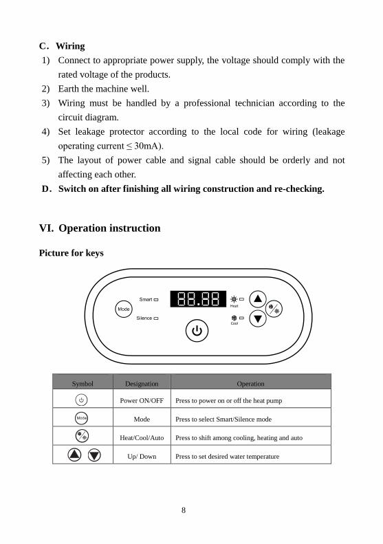
VI. Instruction d’utilisation
Symbole Désignation Fonctionnement
ON/OFF Appuyez pour allumer ou éteindre la pompe à chaleur
Mode Appuyez pour sélectionner le mode Smart/Silence
Chaud/Froid/Auto Appuyez pour passer de Froid à Chaud et Auto
Haut/ Bas Appuyez pour régler la température d’eau souhaitée

9
Note:
① Vous pouvez régler la température de l’eau souhaitée de 12℃ à 35℃.
② Les Droite indique la température de l’eau d’entrée. Les
gauche montre la température de consigne en appuyant sur en
même temps.
③ Après avoir allumé la pompe à chaleur, le ventilateur se met à fonctionner
après 3 minutes. 30 secondes plus tard, le compresseur démarre.
④ Pendant le chauffage, le sera allumé. Durant la période de
refroidissement, le symbole sera allumé. Durant la période de
chauffage/refroidissement automatique, les symboles et
seront tous deux allumés.
2.2.1. Les sélections de modes
① sera allumé lorsque vous démarrez la pompe à chaleur.
② Appuyez sur pour passer en mode silence, le bouton
sera allumé.
Appuyez sur de nouveau pour sortir et entrer du mode SMART.
2.2.2. Dégivrage forcé
① Lorsque la pompe à chaleur chauffe et le compresseur fonctionne en
continu pendant 10 minutes, appuyez sur les deux “ ” et “ ”
pendant 5 secondes pour commencer un dégivrage forcé. (Remarque :
l’intervalle entre 2 dégivrages forcés devrait être plus de 30minutes.)
② La lumière chauffage s’intille lorsque la pompe à chaleur est en dégivrage
forcé ou automatique.
③ Le processus en cours d’exécution et la fin du dégivrage forcé sont les
mêmes que l’auto dégivrage.
10
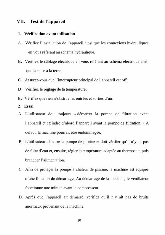
VII. Test de l’appareil
1.Vérification avant utilisation
A.Vérifiez l’installation de l’appareil ainsi que les connexions hydrauliques
en vous référant au schéma hydraulique.
B.Vérifiez le câblage électrique en vous référant au schéma électrique ainsi
que la mise à la terre.
C.Assurez-vous que l’interrupteur principal de l’appareil est off.
D.Vérifiez le réglage de la température;
E.Vérifiez que rien n’obstrue les entrées et sorties d’air.
2.Essai
A. L’utilisateur doit toujours « démarrer la pompe de filtration avant
l’appareil et éteindre d’abord l’appareil avant la pompe de filtration. » A
défaut, la machine pourrait être endommagée.
B. L’utilisateur démarre la pompe de piscine et doit vérifier qu’il n’y ait pas
de fuite d’eau et, ensuite, régler la température adaptée au thermostat, puis
brancher l’alimentation.
C. Afin de protéger la pompe à chaleur de piscine, la machine est équipée
d’une fonction de démarrage. Au démarrage de la machine, le ventilateur
fonctionne une minute avant le compresseur.
D. Après que l’appareil ait démarré, vérifiez qu’il n’y ait pas de bruits
anormaux provenant de la machine.

11
VIII Précautions
1. Attention
A. Veillez à régler une température de l’eau confortable ; évitez une
température trop haute qui surchaufferait ou trop basse qui garderait l’eau
trop fraîche.
B. Veillez à ne pas poser des éléments qui pourraient obstruer la circulation
de l’air à l’entrée ou à la sortie. L’appareil risquerait de perdre en
efficacité, voire de ne plus fonctionner du tout.
C. Veillez à ne pas mettre les mains à la sortie de la pompe à chaleur de
piscine et à aucun moment ne touchez à la grille de protection du
ventilateur.
D. Si vous constatez un quelconque de dysfonctionnement comme, par
exemple, un bruit, de la fumée ou une odeur, une fuite électrique, mettez
l’appareil hors tension immédiatement et contactez votre installateur
professionnel. Ne tentez pas de réparer par vous-même.
E. N’utilisez et ne stockez pas à proximité de la machine des combustibles
gazeux ou liquides comme par exemple des diluants/solvants, peinture ou
essence car il y aurait risque d’incendie.
F. Afin d’optimiser l’efficacité de chauffage, prévoyez d’isoler les
connexions hydrauliques entre la piscine et la pompe à chaleur. Lorsque la
pompe à chaleur fonctionne, utilisez une couverture adaptée pour
recouvrir votre piscine.
G. Le circuit hydraulique entre la piscine et l’appareil doit être à ≤10m, à
défaut l’efficacité chauffage risqué d’être amoindrie.
H. Cette série d’appareils peut atteindre d’un niveau d’efficacité élevé avec
une température d’air entre +15°C~+25°C.
2. Sécurité
A. L’interrupteur principal de mise sous tension de l’appareil doit être hors
de portée des enfants.
B. Si vous subissez une coupure de courant et qu’ensuite le courant est

12
rétabli, la pompe à chaleur se remettra en route automatiquement. Veillez
à mettre l’appareil hors tension lorsqu’il y a une coupure de courant et
faites un reset de la température quand le courant est rétabli.
C. Vérifiez à mettre hors tension l’interrupteur principal de l’appareil en cas
d’orage, vous éviterez ainsi de risquer d’endommager l’appareil avec la
foudre.
D. Si vous n’utilisez pas l’appareil pendant une longue période, pensez à la
débrancher et à vidanger complètement l’eau de la machine
IX Entretien et hivernage
A. Pendant la période hivernale, lorsque vous ne vous baignez pas :
1. Mettez l’appareil hors tension pour éviter d’endommager la machine.
2. Vidangez toute l’eau de la machine.
3. Couvrez la carcasse de la machine avec une bâche afin de la protéger de la
poussière.
B. Veillez à nettoyer la machine uniquement avec des produits ménagers ou
Veillez à mettre hors tension l’appareil avant toute
inspection ou réparation.
Attention: danger d'électrocution
Important ! :
Dévissez le raccord union du tuyau à l’entrée afin de
laisser sortir l’eau.
Quand il y a de l’eau dans l’appareil et qu’elle gèle en
période hivernale, elle risque d’endommager l’échangeur
en titane.

13
de l’eau claire, n’utilisez JAMAIS de produit à base d’essence, de diluant
ou produit combustible similaire.
C. Vérifiez régulièrement les écrous, câbles et connexions.
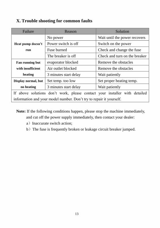
X Guide de dépannages pour les pannes les plus courantes
Echec Raison Solution
Pompe à chaleur ne
fonctionne pas
Aucune puissance Attendre jusqu’à ce que la puissance est
rétabli
Interrupteur est éteint Mettre sous tension
Fusible brûlé Vérifier et changer le fusible
Le disjoncteur est éteint Vérifiez et installez le disjoncteur
Le ventilateur tourne
mais avec un chauffage
insuffisant
Evaporateur bloque Eliminer les obstacles
Sortie d’air bloqué Eliminer les obstacles
3 minutes de tempo au démarrage Attendre patiemment
Affichage normal mais
pas de chauffage
Température de consigne trop basse Réglez la température de chauffage
3 minutes de tempo au démarrage Attendre patiemment
Si les solutions ci-dessus ne fonctionnent pas, s’il vous plaît contactez votre installateur avec des informations
détaillées et le numéro de modèle. N’essayer pas de réparer vous-même.
Remarque: Si vous constatez l’un des cas de figure suivants, arrêtez
immédiatement la machine et mettez hors tension à l’aide l’interrupteur
principal et contactez votre installateur professionnel :
a)Coupure inopinée
b)Le fusible saute régulièrement ou le disjoncteur disjoncte.
14
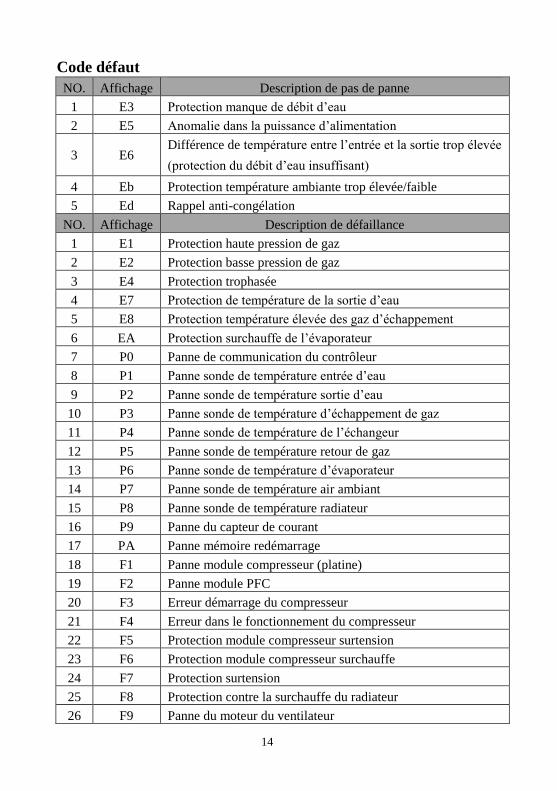
Code défaut
NO. Affichage Description de pas de panne
1 E3 Protection manque de débit d’eau
2 E5 Anomalie dans la puissance d’alimentation
3 E6 Différence de température entre l’entrée et la sortie trop élevée
(protection du débit d’eau insuffisant)
4 Eb Protection température ambiante trop élevée/faible
5 Ed Rappel anti-congélation
NO. Affichage Description de défaillance
1 E1 Protection haute pression de gaz
2 E2 Protection basse pression de gaz
3 E4 Protection trophasée
4 E7 Protection de température de la sortie d’eau
5 E8 Protection température élevée des gaz d’échappement
6 EA Protection surchauffe de l’évaporateur
7 P0 Panne de communication du contrôleur
8 P1 Panne sonde de température entrée d’eau
9 P2 Panne sonde de température sortie d’eau
10 P3 Panne sonde de température d’échappement de gaz
11 P4 Panne sonde de température de l’échangeur
12 P5 Panne sonde de température retour de gaz
13 P6 Panne sonde de température d’évaporateur
14 P7 Panne sonde de température air ambiant
15 P8 Panne sonde de température radiateur
16 P9 Panne du capteur de courant
17 PA Panne mémoire redémarrage
18 F1 Panne module compresseur (platine)
19 F2 Panne module PFC
20 F3 Erreur démarrage du compresseur
21 F4 Erreur dans le fonctionnement du compresseur
22 F5 Protection module compresseur surtension
23 F6 Protection module compresseur surchauffe
24 F7 Protection surtension
25 F8 Protection contre la surchauffe du radiateur
26 F9 Panne du moteur du ventilateur
15
27 Fb Protection coupure de courant du de la plaque de filtre
d’alimentation
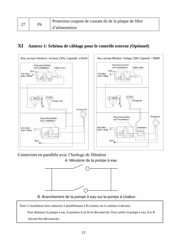
XI Annexe 1: Schéma de câblage pour le contrôle externe (Optionel)
Connexion en parallèle avec l’horloge de filtration
B: Branchement de la pompe à eau sur la pompe à chaleur
Note: L’installateur doit connecter A parallèlement à B (comme sur le schéma ci-dessus).
Pour démarrer la pompe à eau, la position A ou B est déconnectée. Pour arrêter la pompe à eau, A et B
doivent être déconnectés.
A: Minuterie de la pompe à eau

16
Garanties
La pompe à chaleur VESUVIO INVERTER est garantie contre tout défaut de matière et/ou de fabrication pendant une
durée de 3 ans à compter de la date de livraison. Le Titane de l’échangeur est garanti à vie contre la corrosion.
La casse des entrées ou sorties de l’échangeur n’est pas couverte par la garantie en cas de choc ou de manipulation non
adéquate (exemple: déplacement de la PAC par les raccords entrées-sorties). La détérioration de l’échangeur (exemple:
éclatement) en cas de non-respect des consignes d’hivernage n’est pas couverte par la garantie. ette garantie est
conditionnée au strict respect de la notice de montage et d’entretien. La garantie ne s’appliquera pas en cas de
non-respect de ces conditions. Aucune garantie ne saurait être validée à défaut de règlement intégral. Les interventions
au titre de la garantie ne sauraient avoir pour effet de prolonger la durée de celle-ci. La présentation de la facture
d’achat sera rigoureusement exigée lorsque la garantie sera invoquée. Au titre de cette garantie, la seule obligation
incombant à AQUALUX sera, au choix d’AQUALUX, le remplacement gratuit ou la réparation du produit ou de
l’élément reconnu défectueux par les services d’AQUALUX. Tous les autres frais seront à la charge de l’acheteur.
Pour bénéficier de cette garantie, tout produit doit être soumis au préalable au service après-vente d’AQUALUX, dont
l’accord est indispensable pour tout remplacement ou toute réparation.
La garantie ne joue pas en cas de vice apparent. Sont également exclus les défauts et détériorations provoqués par
l’usure normale, les défectuosités résultant d’un montage et/ou d’un emploi non conformes, et les modifications du
produit réalisées sans le consentement écrit et préalable d’AQUALUX.
Garantie légale: A la condition que l’acheteur fasse la preuve du vice caché, le vendeur doit légalement en
réparer toutes les conséquences (article 1641 et suivants du Code civil).
Si l’acheteur s’adresse aux tribunaux, il doit le faire dans un bref délai à compter de la découverte du vice caché
(article 1648 du Code civil).
ECO PARTICIPATION (Directive DEEE)
Conformément à la Directive Européenne 2002/96/CE, et afin d’atteindre un certain nombre d’objectifs en
matière de protection de l’environnement, les règles suivantes doivent être appliquées.
Elles concernent les déchets d’équipement électriques et électroniques (DEEE).
Le pictogrammeci-contre présent sur le produit, son manuel d’utilisation
ou son emballage indique que le produit est soumis à cette réglementation.
Le consommateur doit retourner le produit usager aux points de collecte prévus à cet effet.
En permettant le recyclage des produits, le consommateur contribue à la protection de notre environnement.
Aqualux – 287 avenue de la Massane – 13210 St Rémy de Pce – France
[email protected] / www.aqualux.com

0
FR / EN / DE / NL / ESP
Inverter Swimming Pool Heat Pump

1
Content
I. Application ............................................................................................... 2
II. Features .................................................................................................... 2
III. Technical Parameter ................................................................................. 3
IV. Dimension ................................................................................................ 4
V. Installation instruction.............................................................................. 5
VI. Operation instruction................................................................................ 8
VII. Testing .................................................................................................... 10
VIII. Precautions ............................................................................................. 11
IX. Maintenance ........................................................................................... 12
X. Trouble shooting for common faults ...................................................... 13
XI. Appendix: Heating priority (Optional) ................................................... 15

2
Thank your choosing our product and your trust in our company. To help you
get maximum pleasure from using this product, please read this instruction
manual carefully and operate strictly according to the user manual before
starting the machine, otherwise the machine may be damaged or cause you
unnecessary harm.
I. Application
1- Set swimming pool water temp efficiently and economically to provide you
comfort and pleasure.
2- User may choose the model technical parameter according to professional
guide, this series of swimming pool heater has been optimized in factory
(refer to technical parameter table).
II. Features
1- High efficient titanium heat exchanger.
2- Sensitive and accurate temp control and water temp display.
3- High pressure and low pressure protection.
4- Exceeding low temp auto stop protection.
5- Temp control compulsory defrosting.
6- International brand compressor.
7- Easy installation and operation.

3
III. Technical Parameter
Model VESIN08N VESIN10N VESIN13N VESIN17N VESIN21N
Advised pool volume(m3) 20~40 30~50 40~70 55-85 70-100
Operating air temperature (℃) 0~43
Performance Condition: Air 26°C, Water 26°C, Humidity 80%
Heating capacity (kW) 8.0 9.2 12.5 16.5 20.5
C.O.P 10.8~5.6 11.2~5.5 12.0~5.6 11.8~5.5 12.0~5.6
C.O.P at 50% capacity 8.2 8.6 9.5 9.1 9.2
Performance Condition: Air 15°C, Water 26°C, Humidity 70%
Heating capacity (kW) 6.0 7.0 9.0 11.5 14.0
C.O.P 6.7~3.9 6.6 - 3.8 6.7 - 3.9 6.7 - 3.8 6.7 - 3.9
C.O.P at 50% capacity 6.1 5.8 6.0 6.2 5.9
Rated input power
at air 15°C (kW)
0.19 - 1.3 0.21 - 1.7 0.3 - 2.3 0.36 - 2.9 0.45 - 3.7
Rated input current
at air 15°C (A)
0.83 - 5.6 0.91 - 7.4 1.3 - 10 1.6 - 12.6 1.96 - 16.1
Max input current (A) 7.5 9.0 11.0 15.0 18.5
Power supply 220 - 240V/1 Ph/50Hz
Advised water flux (m³/h) 2~4 3~4 4~6 6~8 8~10
Sound pressure 10m dB(A) 20.5~29.2 21.3~30 21.5~30.2 24.8~34.1 26.2~34.9
Water pipe in-out Spec (mm) 50
Net Dimension LxWxH (mm) 864×349×648 864×349×648 864×349×648 954×349×648 954×349×748
Net Weight (kg) 46 47 49 60 63
Notice:
1. This product can work well under air temp 0℃~+43℃, efficiency will
not be guaranteed out of this range. Please take into consideration that the pool
heater performance and parameters are different under various conditions.
2. Related parameters are subject to adjustment periodically for technical
improvement without further notice. For details please refer to nameplate.
4
IV. Dimension
※ Above data is subject to modification without notice.
Note:
The picture above is the specification diagram of the pool heater, for
technician’s installation and layout reference only. The product is subject to
adjustment periodically for improvement without further notice.
A B C D E F G H
VESIN08N 324 560 330 349 872 250 74 654
VESIN10N 324 560 330 349 872 250 74 654
VESIN13N 324 560 330 349 872 290 74 654
VESIN17N 324 590 330 349 962 350 74 654
VESIN21N 324 590 325 349 962 350 74 754
Name Size(mm)
Model

5
V. Installation instruction
1. Drawing for water pipes connection
(Notice:The drawing is just for demonstration, and layout of the pipes is only for reference.)
2. Electric Wiring Diagram
Note:1) Must be hard wired, no plug allowed.
2) The swimming pool heater must be earthed well.

6
Options for protecting devices and cable specification
※ Above data is subject to modification without notice.
Note: The above data is adapted to power cord ≤ 10m. If power cord is>10m, wire
diameter must be increased. The signal cable can be extended to 50m at most.
3. Installation instruction and requirement
The heat pump must be installed by a professional team. The users are not
qualified to install by themselves, otherwise the heat pump might be damaged
and risky for users’ safety.
A. Installation
1) The inlet and outlet water unions can’t bear the weight of soft pipes. The
heat pump must be connected with hard pipes!
2) In order to guarantee the heating efficiency, the water pipe length should be
≤10m between the pool and the heat pump.
MODEL VESIN08N VESIN10N VESIN13N VESIN17N VESIN21N
Breaker
Rated Current A 9.0 11.0 13.5 18.0 22.0
Rated Residual
Action Current
mA
30 30 30 30 30
Fuse A 9.0 11.0 13.5 18.0 22.0
Power Cord (mm2) 3×1.5 3×2.5 3×2.5 3×2.5 3×4
Signal cable (mm2) 3×0.5 3×0.5 3×0.5 3×0.5 3×0.5

7
B. Installation instruction
1) Location and size
The heat pump should be installed in a place with good ventilation
2) The frame must be fixed by bolts (M10) to concrete foundation or brackets.
The concrete foundation must be solid and fastened; the bracket must be strong
enough antirust treated;
3) Please don’t stack substances that will block air flow near inlet or outlet area,
and there is no barrier within 50cm behind the main machine, or the efficiency
of the heater will be reduced or even stopped;
4) The machine needs an appended pump (Supplied by the user). The
recommended pump specification-flux: refer to Technical Parameter, Max. lift
≥10m;
5) When the machine is running, there will be condensation water discharged
from the bottom, please pay attention to it. Please hold the drainage nozzle
(accessory) into the hole and clip it well, and then connect a pipe to drain the
condensation water out.
* Minimum distance
filter
water processor
water switch
8
C.Wiring
1) Connect to appropriate power supply, the voltage should comply with the
rated voltage of the products.
2) Earth the machine well.
3) Wiring must be handled by a professional technician according to the
circuit diagram.
4) Set leakage protector according to the local code for wiring (leakage
operating current ≤ 30mA).
5) The layout of power cable and signal cable should be orderly and not
affecting each other.
D.Switch on after finishing all wiring construction and re-checking.
VI. Operation instruction
Picture for keys
Symbol Designation Operation
Power ON/OFF Press to power on or off the heat pump
Mode Press to select Smart/Silence mode
Heat/Cool/Auto Press to shift among cooling, heating and auto
Up/ Down Press to set desired water temperature

9
Note:
① You may set the desired water temperature from 12 to 35℃.
② The on the right shows the inlet water temperature. The on the
left shows the set temperature by pressing or button.
③ After you turn on the heat pump, the fan will start to run in 3 minutes. In
another 30 seconds, the compressor will start to run.
④ During heating, the will be light. During cooling, will be
light. During auto heating cooling, and will be both light.
2.2.1. Mode selections
① will be light as standard when you turn on the heat pump.
② Press the button to enter the Silence mode, the will be
light.
Press the button again to exit and enter the SMART mode.
2.2.2. Compulsory defrosting
① When the heat pump is heating and the compressor is working
continuously for 10 minutes, press both “ ” and “ ” buttons for 5
seconds to start compulsory defrosting. (Note: the interval between
compulsory defrosting should be more than 30 minutes.)
② The heating light will be twinkling when heat pump is in compulsory or
auto defrosting.
③ The running process and ending of compulsory defrosting are the same as
auto-defrosting.

10
VII. Testing
1.Inspection before use
A. Check installation of the whole machine and the pipe connections
according to the pipe connecting drawing;
B. Check the electric wiring according to the electric wiring diagram and
earthing connection;
C. Make sure that the main machine power switch is off;
D. Check the temperature setting;
E. Check the air inlet and outlet.
2.Trial
A. The user must “Start the Pump before the Machine, and Turn off the
Machine before the Pump”, or the machine will be damaged;
B. The user should start the pump, check for any leakage of water; and then
set suitable temperature in the thermostat, and then switch on power
supply;
C. In order to protect the swimming pool heater, the machine is equipped
with a time lag starting function, when starting the machine, the blower
will run 1 minutes earlier than the compressor;
D. After the swimming pool heater starts up, check for any abnormal noise
from the machine.

11
VIII. Precautions
1. Attention
A. Set proper temperature in order to get comfortable water temperature to
avoid overheating or overcooling;
B. Please don’t stack substances that can block air flow near inlet or outlet
area, or the efficiency of the heater will be reduced or even stopped;
C. Please don’t put hands into outlet of the swimming pool heater, and don’t
remove the screen of the fan at any time;
D. If there are abnormal conditions such as noise, smell, smoke and electrical
leakage, please switch off the machine immediately and contact the local
dealer. Don’t try to repair it yourself;
E. Don’t use or stock combustible gas or liquid such as thinners, paint and
fuel to avoid fire;
F. In order to optimize the heating effect, please install heat preservation
insulation on pipes between swimming pool and the heater. During
running period of the swimming pool heater, please use a recommended
cover on the swimming pool;
G. Connecting pipes of the swimming pool and the heater should be ≤10m,
or the heating effect of the heater cannot be ensured;
H. This series of machines can achieve high efficiency under air temperature
of +15℃~+25℃.
2. Safety
A. Please keep the main power supply switch far away from the children;
B. When a power cut happens during running, and later the power is restored,
the heater will start up automatically. So please switch off the power
supply when there is a power cut, and reset temp when power is restored;
C. Please switch off the main power supply in lightning and storm weather to
prevent from machine damage that caused by lightning;
D. If the machine is stopped for a long time, please cut off the power supply
and drain water clear of the machine by opening the tap of inlet pipe.

12
IX. Maintenance
A. In winter season when you don’t swim:
1. Cut off power supply to prevent any machine damage
2. Drain water clear of the machine.
3. Cover the machine body when not in use.
B. Please clean this machine with household detergents or clean water,
NEVER use gasoline, thinners or any similar fuel.
C. Check bolts, cables and connections regularly.
“Cut off” power supply of the heater before
cleaning, examination and repairing
Caution: Danger of electric shock
!!Important:
Unscrew the water nozzle of inlet pipe to
let the water flow out.
When the water in machine freezes in winter
season, the titanium heat exchanger may be
damaged.
13
X. Trouble shooting for common faults
Failure Reason Solution
Heat pump doesn’t
run
No power Wait until the power recovers
Power switch is off Switch on the power
Fuse burned Check and change the fuse
The breaker is off Check and turn on the breaker
Fan running but
with insufficient
heating
evaporator blocked Remove the obstacles
Air outlet blocked Remove the obstacles
3 minutes start delay Wait patiently
Display normal, but
no heating
Set temp. too low Set proper heating temp.
3 minutes start delay Wait patiently
If above solutions don’t work, please contact your installer with detailed
information and your model number. Don’t try to repair it yourself.
Note: If the following conditions happen, please stop the machine immediately,
and cut off the power supply immediately, then contact your dealer:
a)Inaccurate switch action;
b)The fuse is frequently broken or leakage circuit breaker jumped.

14
Failure code
NO. Display Not failure description
1 E3 No water protection
2 E5 Power supply excesses operation range
3 E6 Excessive temp difference between inlet and outlet
water(Insufficient water flow protection)
4 Eb Ambient temperature too high or too low protection
5 Ed Anti-freezing reminder
NO. Display Failure description
1 E1 High pressure protection
2 E2 Low pressure protection
3 E4 3 phase sequence protection (three phase only)
4 E7 Water outlet temp too high or too low protection
5 E8 High exhaust temp protection
6 EA Evaporator overheat protection (only at cooling mode)
7 P0 Controller communication failure
8 P1 Water inlet temp sensor failure
9 P2 Water outlet temp sensor failure
10 P3 Gas exhaust temp sensor failure
11 P4 Evaporator coil pipe temp sensor failure
12 P5 Gas return temp sensor failure
13 P6 Cooling coil pipe temp sensor failure
14 P7 Ambient temp sensor failure
15 P8 Cooling plate sensor failure
16 P9 Current sensor failure
17 PA Restart memory failure
18 F1 Compressor drive module failure
19 F2 PFC module failure
20 F3 Compressor start failure
21 F4 Compressor running failure
22 F5 Inverter board over current protection
23 F6 Inverter board overheat protection
24 F7 Current protection
25 F8 Cooling plate overheat protection
26 F9 Fan motor failure

15
27 Fb Power filter plate No-power protection
XI. Appendix: Heating priority (Optional)
Parallel connection with filtration clock
A: Water pump timer
B: Water pump wiring of Heat Pump
Note: The installer should connect A parallel with B (as above picture). To start the water
pump, condition A or B is connected. To stop the water pump, both A and B should be
disconnected.

16
Guarantee
The VESUVIO INVERTER heat pump is guaranteed against all material and/or manufacturing defects for 3 years as from the date of delivery.
The titanium exchanger is guaranteed against rust for 3 years as from the date of delivery.
The couplings exchanger are not covered by the warranty in case of impact or not properly handling ( do not lift heat pumps with the couplings).
The exchanger is not covered under warranty in case of non-observance of wintering
procedure (ex burst by frost).
These guarantees are granted subject to strict compliance with the assembly and maintenance instructions. The guarantee will not apply in the event of
non-compliance with these conditions.
No guarantee can be granted if the goods have not been paid for in full.
No repairs or replacements carried out under guarantee can result in any prolongation of the said period of guarantee.
The purchase invoice must be forwarded with any claims under guarantee.
Under the terms of this guarantee, the sole obligation placed on AQUALUX is replacement or repair free of charge, as AQUALUX sees fit, of the product or element
found to be defective by the competent AQUALUX department. All other costs must be met by the purchaser.
To benefit from this guarantee, all the products concerned must be forwarded beforehand to the AQUALUX after-sales department, whose approval is essential for all
replacements or repairs in workshop.
The guarantee does not cover visible defects. Does not cover defects or damage caused by normal wear and tear, defects resulting from faulty assembly and/or misuse,
or any modifications made to the product without the prior written approval of AQUALUX.
Legal guarantee: provided that the purchaser is able to provide proof of a hidden defect, the seller is required by law to make good all the consequences
thereof (article 1641 and seq. of the French civil code).
If the purchaser brings a claim before the courts, he must do so in a short time from the date at which the defect is detected (article 1648 of the French civil
code).
ECO PARTICIPATION (DEEE directive)
In accordance with the European Directive 2002/96/EC, and in order to reach a number of environmental protection objectives, the following rules must be obeyed.
These objectives apply to waste from electrical and electronic equipment (DEEE).
The pictogram attached to the product, the user manual and the packaging indicates that the product is subject to this regulation.
Consumers must return the used products to the collection points provided.
By enabling the products to be recycled, consumers contribute to the protection of our environment. This is an ecological gesture.
287 Ave de la Massane – 13210 SAINT REMY DE PROVENCE – France
[email protected] / www.aqualux.com

0
INSTALLATIONS
UND
BENUTZERHANDBUCH
FR / EN / DE / NL / ESP
Inverter Wärmepumpe für Swimmingpool

Inhaltsverzeichnis
I. Verwendungszweck .................................................................................. 2
II. Eigenschaften ........................................................................................... 2
III. Technische Daten ..................................................................................... 3
IV. Dimension ................................................................................................ 4
V. Einbauanleitung ....................................................................................... 5
VI. Bedienungs- und Gebrauchsanleitung...................................................... 8
VII. Überprüfungen ....................................................................................... 10
VIII. Sicherheitshinweise ................................................................................ 11
IX. Wartung .................................................................................................. 12
X. Problemlösungen .................................................................................... 13
XI. Anhang : Schaltplan für Zwangseinschaltung der Filterpumpe (Optional) ............. 15

2
Vielen Dank, dass Sie sich für unser Erzeugnis entschieden haben und unserem
Unternehmen Ihr Vertrauen entgegenbringen.
Damit Sie dieses Erzeugnis uneingeschränkt nutzen und alle Annehmlichkeiten
genießen können, die Ihnen dasselbe bietet, lesen Sie bitte diese
Bedienungsanleitung sorgfältig durch und beachten Sie die hierin gegebenen
Hinweise strikt, bevor Sie das Gerät in Betrieb nehmen, damit das Gerät nicht
beschädigt wird oder Ihnen unnötigen Schaden zufügt.
I. Verwendungszweck
1- Diese Wärmepumpe wird die Wassertemperatur Ihres Swimmingpools
wirksam und wirtschaftlich einstellen und Ihnen somit Komfort und Genuss
bieten.
2- Der Anwender wählt das Gerät entsprechend technischen Daten aus, um die
seinen Bedürfnissen am besten entsprechende Heizleistung zu erzielen (siehe
dazu die Tabelle mit den technischen Daten).
II. Eigenschaften
1- Leistungsfähiger Titan-Wärmetauscher.
2- Empfindliche und genaue Temperaturregelung/Anzeige.
3- Hochdruckschutz und Unterdruckschutz.
4- Leistungsschalter für Temperaturunterschreitung.
5- Temperatureinstellung für automatisches Enteisen.
6- International bekanntes Kompressorfabrikat.
7- Einfacher Einbau und einfache Bedienung.

3
III. Technische Daten
Modell VESIN08N VESIN10N VESIN13N VESIN17N VESIN21N
Empfohlene Beckengröße- m³ 20~40 30~50 40~70 55-85 70-100
Einsatztemperatur (℃ ) 0~43
Betriebsbedingung: Luft 26°C, Wasser 26°C, Feuchtigkeit 80%
Heizleistung (kW) 8.0 9.2 12.5 16.5 20.5
COP 10.8~5.6 11.2~5.5 12.0~5.6 11.8~5.5 12.0~5.6
COP bei 50% Geschwindigkeit 8.2 8.6 9.5 9.1 9.2
Betriebsbedingung: Luft 15°C, Wasser 26°C, Feuchtigkeit 70%
Heizleistung (kW) 6.0 7.0 9.0 11.5 14.0
COP 6.7~3.9 6.6 - 3.8 6.7 - 3.9 6.7 - 3.8 6.7 - 3.9
COP bei 50% Geschwindigkeit 6.1 5.8 6.0 6.2 5.9
Leistungsaufnahme bei
Lufttemperatur 15℃(KW) 0.19 - 1.3 0.21 - 1.7 0.3 - 2.3 0.36 - 2.9 0.45 - 3.7
Nenneingangsstrom bei
Lufttemperatur 15℃(A) 0.83 - 5.6 0.91 - 7.4 1.3 - 10 1.6 - 12.6 1.96 - 16.1
Max. Nenneingangsstrom (A) 7.5 9.0 11.0 15.0 18.5
Stromversorgung 220 - 240V/1 Ph/50Hz
Empfohlener Wasserdurchfluss
(m³/h) 2~4 3~4 4~6 6~8 8~10
Max, Schalldruck 10m dB(A) 20.5~29.2 21.3~30 21.5~30.2 24.8~34.1 26.2~34.9
Anschluss ein – aus (mm) 50
Maße L x B x H (mm) 864×349×648 864×349×648 864×349×648 954×349×648 954×349×748
Netto Gewicht (kg) 46 47 49 60 63
Hinweis:
1- Maschine ist für den Betrieb bei einer Lufttemperatur von 0 ℃~+43 ℃ ausgelegt.
Der einwandfreie Betrieb außerhalb dieses Bereichs kann nicht garantiert werden. Bitte
bedenken Sie, dass die Leistung der Poolheizung unter unterschiedlichen Bedingungen
schwanken kann. Lassen Sie sich dazu von Ihrem Fachhändler entsprechend beraten

4
2- Technische Änderungen vorbehalten. Weitere Angaben dazu siehe die Abdeckblende
der Wärmepumpe.
IV. Dimension
※Änderungen vorbehalten.
Anmerkung:
Die obenstehende Maßskizze der Wärmepumpe soll dem Installateur als
Orientierung dienen. Änderungen sind vorbehalten.
A B C D E F G H
VESIN08N 324 560 330 349 872 250 74 654
VESIN10N 324 560 330 349 872 250 74 654
VESIN13N 324 560 330 349 872 290 74 654
VESIN17N 324 590 330 349 962 350 74 654
VESIN21N 324 590 325 349 962 350 74 754
Größe (mm)
Modell

5
V. Einbauanleitung
1. Skizze für den Einbau der Wasserleitungen
(Bitte beachten Sie: Diese Skizze der Anordnung der Rohrleitungen dient lediglich als Orientierung.)
2. Elektroanschluss
Anmerkung:1) Kabelverbindung, kein Stecker.
2) Die Poolheizung muss geerdet werden.
Für Stromversorgung: 230V 50Hz

6
3. Elektroanschluss
Optionen für Leistungsschutzschalter und technische Daten für Leitungen
※Änderungen vorbehalten.
ANMERKUNG: Die oben genannten Daten gelten für Netzkabel ≤10m. Wenn das
Netzkabel >10m ist, muss der Kabeldurchmesser erhöht werden. Das Signalkabel kann
höchstens auf 50 m verlängert werden.
4. Installation und Wartung
Die Wärmepumpe muss von einem Fachbetrieb installiert werden. Der
Benutzer ist nicht qualifiziert, sie selbst zu installieren, da ansonsten die
Wärmepumpe beschädigt werden kann und Sicherheitsrisiken für den Nutzer
entstehen können.
A. Hinweise zur Installation:
1) Die Wasseranschlüsse sind nicht dafür ausgelegt, das Gewicht von
Schlauchleitungen zu tragen. Die Wärmepumpe muss mit festen Rohren
angeschlossen werden!
2) Um die Heizleistung gewährleisten zu können, sollte die Länge der Leitung
zwischen Pool und der Wärmepumpe 10 m nicht überschreiten.
MODELL VESIN08N VESIN10N VESIN13N VESIN17N VESIN21N
Unterbrecher
Nennstrom A 9.0 11.0 13.5 18.0 22.0
Nennfehlstrom
mA 30 30 30 30 30
Sicherung A 9.0 11.0 13.5 18.0 22.0
Netzkabel ( mm2
) 3×1.5 3×2.5 3×2.5 3×2.5 3×4
Signalkabel ( mm2 ) 3×0.5 3×0.5 3×0.5 3×0.5 3×0.5

7
B. Installationsanweisung
1) Lage und Größe
Die Wärmepumpe sollte an einem Ort mit einer guten Belüftung installiert warden
2) Der Rahmen ist mit Schrauben (M10) an einem Betonfundament oder an
Trägern oder Halterungen zu befestigen. Das Betonfundament muss stabil und
fest montiert sein; die Träger oder Halterungen müssen entsprechend stabil und
tragfähig und korrosionsgeschützt sein.
3) Bitte platzieren Sie keine Gegenstände so, dass sie den Luftstrom vor oder
hinter der Wärmepumpe blockieren könnten. Die Wärmepumpe muss in einem
Abstand von mindestens 50 cm von allen Konstruktionen oder Hindernissen
aufgestellt werden; ansonsten kann die Leistung der Heizung beeinträchtigt
oder die Funktion des Gerätes sogar verhindert werden.
4) Das Gerät benötigt eine Umwälzpumpe (Filterpumpe) (die vom Nutzer
beizustellen ist). Empfohlene Pumpleistung: siehe die Technischen Daten,
größte Förderhöhe ≥ 10 m.
5) Wenn das Gerät in Betrieb ist, wird Kondenswasser aus dem Boden des
Gerätes austreten, das in einen Ablauf geleitet werden muss. Bitte führen Sie
* Mindestabstand
Wasseraufbereitungsanlage
Rückschlagventil
Kugelhähne
8
dazu die Ablauftülle (Zubehörteil) in das Loch ein und befestigen Sie sie sicher
und schließen Sie sie dann an eine Abflussleitung an, um das Kondenswasser
entsprechend abzuleiten.
C.Verkabelung
1) Schließen Sie das Gerät an eine geeignete Spannungsquelle an; die
Versorgungsspannung muss der für das Erzeugnis angegebenen Nennspannung
entsprechen.
2) Erden Sie das Gerät.
3) Der Anschluss muss durch einen Fachmann entsprechend dem
Anschlussplan hergestellt werden.
4) Stellen Sie den Fehlerstromschutzschalter entsprechend den örtlich
geltenden Vorschriften für elektrische Anschlüsse ein (Betriebs-Fehlerstrom ≤
30 mA).
5) Das Leistungskabel und das Signalkabel sind getrennt anzuordnen.
D.Schalten Sie das Gerät ein, nachdem Sie die Installation abgeschlossen
und ein zweites Mal überprüft haben.
VI. Bedienungs- und Gebrauchsanleitung
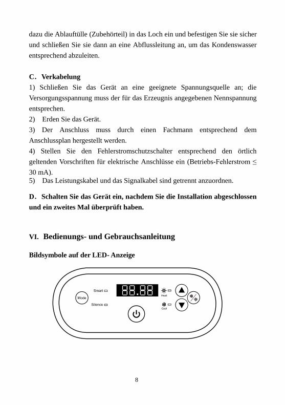
Bildsymbole auf der LED- Anzeige
9
Hinweis:
① Sie können die gewünschte Wassertemperatur zwischen 12℃ und 35℃
einstellen.
② “ ” auf der rechten Seite wird die Wassertemperatur des Zulaufs
angezeigt. “ ” auf der linken Seite wird die durch Betätigen von
oder eingestellte Temperatur angezeigt.
③ Nachdem Sie die Wärmepumpe eingeschaltet haben,dauert es etwa 3
Minuten bis der Lüfter anläuft. In weiteren 30 Sekunden startet der
Kompressor.
④ Während des Erwärmens wird aufleuchten, Während des Kühlens
wird aufleuchten, Während des Auto-Modus wird und
aufleuchten,
1. Modus auswählen
① leuchtet beim Einschalten der Wärmepumpe in der
Standardeinstellung.
② Betätigen Sie die Taste, um den Silence Modus zu wählen,
anschließend leuchtet das Symbol .
Betätigen Sie die Taste nochmals, um den Silence Modus zu
verlassen und den SMART Modus zu wählen.
2. Obligatorische Abtaufunktion
① Wenn die Wärmepumpe aufheizt und der Kompressor kontinuierlich für
10 Minuten arbeitet, halten Sie die Tasten “ ” und “ ” für 5 Sekunden
lang gedrückt, um die obligatorische Abtaufunktion zu starten.
② Das Symbol Heizmodus blinkt, sobald die Wärmepumpe im
obligatorischen Abtaumodus ist.
③ Der Vorgang sowie die Beendigung sind identisch zum automatischen
Abtauen.

10
VII. Überprüfungen
1. Überprüfung vor dem Gebrauch
A.Überprüfen Sie die Installation der Rohrleitungen und der Wärmepumpe
anhand des Rohrleitungsschemas für die Wärmepumpe.
B.Überprüfen Sie den elektrischen Anschluss anhand des Schaltplans und des
Erdungsplans.
C.Vergewissern Sie sich, dass die Netzstromversorgung abgeschaltet ist.
D.Überprüfen Sie die Temperatureinstellung.
E.Überprüfen Sie den Lufteinlass und Luftauslass.
2. Probelauf
A.Bitte nehmen Sie die Pumpe vor der Wärmepumpe in Betrieb und schalten
Sie sie nach der Wärmepumpe aus, damit Wasser während der gesamten
Betriebszeit durch das System gepumpt wird.
B. Schalten Sie die Pumpe ein, stellen Sie sicher, dass der richtige
Wasserdruck vorhanden ist, stellen Sie am Thermostaten die gewünschte
Temperatur ein und schalten Sie danach die Stromversorgung ein.
C. Zum Schutz der Poolheizung ist die Wärmepumpe mit einer
Einschaltverzögerungsfunktion ausgestattet. Nach dem Einschalten der
Wärmepumpe läuft das Gebläse eine Minute lang, bevor der Kompressor
zuschaltet.
D.Prüfen Sie nach dem Anlaufen der Poolheizung, ob von der Wärmepumpe
irgendwelche anormalen Geräusche ausgehen.

11
VIII. Sicherheitshinweise
1. Vorsicht!
A. Stellen Sie die gewünschte Temperatur ein, um eine angenehme
Wassertemperatur zu erhalten; so werden Sie ein Überhitzen
beziehungsweise Unterkühlen vermeiden.
B. Bitte platzieren Sie keine Gegenstände, die den Luftstrom blockieren
können, in der Nähe des Einlass- beziehungsweise Auslassbereiches;
andernfalls kann die Leistung der Wärmepumpe reduziert werden oder das
Gerät betriebsunfähig werden.
C. Bitte führen Sie Ihre Hände nicht in den Auslass der Poolheizung und
entfernen Sie keinesfalls das Schutzgitter vom Gebläse.
D. Wenn anormale Bedingungen auftreten, wie zum Beispiel anormale
Geräuschbildung, Geruch, Rauchbildung oder elektrische Ableitung,
schalten Sie das Gerät sofort aus und setzen Sie sich mit Ihrem örtlichen
Fachhändler in Verbindung. Versuchen Sie nicht, das Gerät selbst zu
reparieren.
E. Verwenden und lagern Sie keine brennbaren Gase oder Flüssigkeiten, wie
zum Beispiel Verdünnungsmittel, Anstrichstoffe oder Kraft- oder
Brennstoffe, in der Nähe der Wärmepumpe, um Brände zu vermeiden.
F. Um die Heizwirkung zu optimieren, installieren Sie bitte eine
Wärmeisolierung an den Rohrleitungen zwischen dem Swimmingpool und
der Heizung. Wenn die Wärmepumpe in Betrieb ist, verwenden Sie bitte
die empfohlene Abdeckung auf dem Swimmingpool, um Wärmeverluste
durch Verdampfung zu vermeiden.
G. Die Wärmepumpe ist in einem Abstand von ≤10 m von dem
Swimmingpool aufzustellen; andernfalls kann die Heizwirkung der
Heizung nicht gewährleistet werden.
H. Diese Baureihe von Wärmepumpen kann bei Lufttemperaturen von
+15 ℃ ~ +25 ℃ eine hohe Heizwirkung erzielen.

12
2. Sicherheitshinweise
A.Bitte sorgen Sie dafür, dass der Hauptschalter für die Stromversorgung für
Kinder unzugänglich ist.
B.Bitte schalten Sie den Hauptschalter für die Stromversorgung bei Gewitter
und stürmischem Wetter aus, um Schäden durch Blitzschlag zu
vermeiden.
C.Wenn die Wärmepumpe über einen längeren Zeitraum nicht in Betrieb ist,
schalten Sie bitte die Stromversorgung ab und entleeren Sie das Wasser aus
der Wärmepumpe, indem Sie den Hahn des Zuleitungsrohres öffnen.
IX. Wartung
A. Beachten Sie folgende Hinweise für die Winterzeit, in der Sie den Pool
nicht zum Baden benutzen:
a) Schalten Sie die Stromversorgung ab, um Geräteschäden zu verhindern.
b) Lassen Sie das Wasser aus dem Gerät ab.
c) Decken Sie die Wärmepumpe entsprechend ab, um das Eindringen von
Schmutz zu verhindern.
Schalten Sie vor jeder Überprüfung oder Instandsetzung
die Stromversorgung der Heizung ab.
Achtung: Elektroschock Gefahr
!!Wichtiger Hinweis:
Schrauben Sie den Wasseranschluss der Zulaufleitung ab,
um das Wasser ablaufen zu lassen.
Wenn das Wasser im Winter im Gerät gefriert, kann der
Titan-Wärmetauscher beschädigt werden.

13
B. Bitte verwenden Sie zum Reinigen dieser Wärmepumpe nur
Haushaltsreiniger oder sauberes Wasser, jedoch NIEMALS Benzin,
Verdünnungsmittel oder ähnliche Mineralölerzeugnisse.
C. Überprüfen Sie Verschraubungen, Kabel und Anschlüsse in regelmäßigen
Abständen.
X. Problemlösungen
Fehler Grund Lösung
Wasserpumpe startet
nicht
Kein Strom Warten Sie, bis der Strom eingeschaltet wird
Hauptschalter ist aus Hauptschalter einschalten
Sicherung durchgebrannt Überprüfen Sie die Sicherungen und
wechseln Sie diese
Schutzschalter ist aus Überprüfen Sie ihn und schalten Sie den
Schutzschalter ein
3 Minuten Startverzögerung Warten Sie geduldig
Lüfter läuft aber mit
unzureichender Heizung
Verdampfer verstopft Entfernen Sie eventuelle Hindernisse
Luftauslass verstopft / blockiert Entfernen Sie eventuelle Hindernisse
Display normal, aber
keine Heizung
Temperatur zu niedrig eingestellt Stellen Sie die richtige Temperatur ein
3 Minuten Startverzögerung Warten Sie geduldig
Wenn die oben angegebenen Lösungen nicht wirksam sein sollten, wenden Sie sich bitte an Ihren Installateur mit
detaillierten Informationen und Ihrer Modellnummer. Versuchen Sie nicht, es selbst zu reparieren.
Achtung: Wenn die folgenden Bedingungen eintreten, schalten Sie das Gerät bitte sofort
ab, schalten Sie den Handschalter für die Stromversorgung aus und setzen Sie sich mit
Ihrem örtlichen Fachhändler in Verbindung.
a)Falsche Schaltfunktion.
b)Die Sicherung brennt häufig durch beziehungsweise der Leistungsschutzschalter löst aus.

14
Fehlercode
NR, Display Beschreibung des keine Fehler
1 E3 Schutz vor Trockenlauf
2 E5 Kein Fehler, Stromversorgung übersteigt den Betriebsbereich
3 E6 Übermäßiger Temperaturunterschied zwischen Wasser am Einlass und am Auslass
(Schutz vor zu geringem Wasserdurchsatz) 4 Eb Schutz vor zu hoher oder zu niedriger Umgebungstemperatur
5 Ed Erinnerung an Frostschutzmittel
NR, Display Beschreibung des Fehlers
1 E1 Schutz vor Überdruck
2 E2 Schutz vor zu niedrigem Druck
3 E4 3-Phasen-Sequenz Schutz (nur dreiphasig)
4 E7 Schutz vor zu hoher oder zu niedriger Wassertemperatur am Auslass
5 E8 Schutz vor hoher Temp am Ausgang
6 EA Überhitzungsschutz an Kühlspule (Verdampfer)
7 P0 Fehler bei Controller Kommunikation
8 P1 Sensorfehler des Temp-Sensors an Wassereinlass
9 P2 Sensorfehler des Temp-Sensors an Wasserauslass
10 P3 Sensorfehler des Temp-Sensors an Gasauslass
11 P4 Sensorfehler des Temp-Sensors Heizspule (Verdampfer)
12 P5 Sensorfehler des Temp-Sensors an Gasrückführung
13 P6 Sensorfehler des Temp-Sensors an Kühlspule (Wärmetauscher) im Kühlmodus
14 P7 Sensorfehler an Temp-Sensor Umgebungtemperatur
15 P8 Sensorfehler des Temp-Sensors an Kühlplatte
16 P9 Aktueller Sensor Fehler
17 PA Fehler Restart Memory
18 F1 Modulfehler Kompressor-Antrieb
19 F2 PFC Modul Fehler
20 F3 Fehler bei Kompressor Start
21 F4 Fehler bei Kompressor-Lauf
22 F5 Überstromschutz an Wandler-Board
23 F6 Überhitzungsschutz an Wandler-Board
24 F7 Überstromschutz
25 F8 Überhitzungsschutz an Kühlplatte
26 F9 Fehler Ventilatormotor
27 Fb Schutz vor fehlendem Strom an Stromfilter

15
XI. Anhang : Schaltplan für Zwangseinschaltung der Filterpumpe (Optional)
Parallelschaltung mit Filteruhr
A: Timer Filter pumpe
B: Verkabelung Wasserpumpe der Wärmepumpe
Hinweis: Der Installateur sollte A parallel zu B (wie oben Bild) verbinden. Um die Filterpumpe zu starten, ist es
wichtig, dass A oder B verbunden sind. Um die Filterpumpe zu stoppen, müssen sowohl A als auch B getrennt
werden

16
Garantie
Auf die Wärmepumpe VESUVIO INVERTER gibt es bei allen Material- und/oder Herstellungsdefekten 3 Jahre lang Garantie, gültig ab
dem Lieferdatum.
Der Titan Wärmetauscher ist vor Korrosion für einen Zeitraum von 3 Jahren ab dem Lieferdatum garantiert.
Bei Schäden am Ein- und Ausgang des Wärmetauschers ist die Garantie im Falle eines Aufschlags oder eines nicht sachgemäßen
Umgangs (z.B. ein Verschieben der Wärmepumpe durch die In und Output Anschlüsse) nicht gewährleistet.
Die Verschlechterung des Wärmetauschers (z.B. ein Zerspringen) im Falle einer Nichteinhaltung der Überwinterungs-Anweisungen ist
nicht von uns garantiert.
Diese Garantie ist abhängig von der strikten Einhaltung der Installationsanleitung und der Pflege. Die Garantie gilt nicht bei
Nichteinhaltung dieser Bedingungen.
Eine Intervention im Rahmen der Garantie verlängert nicht die Dauer der Garantie.
Die Präsentation der Einkaufsrechnung wird streng erforderlich, wenn die Garantie eingesetzt werden soll.
Im Rahmen dieser Garantie ist die einzige Verpflichtung von Aqualux der kostenfreie Austausch, oder die Reparatur des Produkts oder
einer fehlerhaften Komponente die durch einer Dienststelle von Aqualux als fehlerhat definiert wurden.
Alle anderen Kosten werden vom Käufer übernommen.
Um von dieser Garantie zu profitieren, muß das Produkt im voraus zu dem Aqualux Kundendienst, dessen Zustimmung für jeden Ersatz
unentbehrlich ist.
Gesetzliche Garantie: Sofern der Käufer den Nachweis eines versteckten Mangels macht, muß der Verkäufer für alle rechtlichen Folgen
haften (Artikel 1641 des Bürgerlichen Gesetzbuchs).
Wenn der Käufer vor Gericht geht, muß dies innerhalb kurzer Zeit nach Entdeckung des versteckten Mangels geschehen (Artikel 1648 des
Bürgerlichen Gesetzbuchs).
ECO BETEILIGUNG (WEEE-Richtlinie)
In Übereinstimmung mitder Europäischen Richtlinie 2002/96/ EGundzur Erreichungeiner Reihe vonUmweltzielen, müssen folgende
Regelnangewandt werden.
Sie beziehen sich aufelektrische und elektronische Geräte(WEEE).
Das angebrachte Symbol auf unseren Produkten bezeichnet die Notwedigkeit einer getrennten Müllsammlung und einer Sortierung
des restlichen Hausmülls.
Der Verbraucher muss das Produkt zur Entsorgung in einer Abfallsammelstelle abgeben.
Indem man das Recycling des Produktes ermöglicht, trägt der Verbraucher zu dem Schutz unserer Umwelt bei.
287 Ave de la Massane – 13210 SAINT REMY DE PROVENCE – France
[email protected] / www.aqualux.com

INSTALLATIE
EN
GEBRUIKSAANWIJZING
FR / EN / DE / NL / ESP
Verwarmingspomp voor zwembad
1
Content
I. Toepassing ................................................................................................ 2
II. Kenmerken ............................................................................................... 2
III. Technische parameters ............................................................................. 3
IV. Afmetinge ................................................................................................ 4
V. Installatie-instructies ................................................................................ 5
VI. Bedieningsinstructies ............................................................................... 8
VII. Testen van het apparaat ............................................................................ 9
VIII. Voorzorgsmaatregelen ............................................................................ 10
IX. Onderhoud.............................................................................................. 12
X. Probleemoplossingen voor veel voorkomende fouten ........................... 13
XI. Appendix 1: Bedradingsschema Prioriteit Verwarming (Optioneel) ...... 15
2
Wij bedanken u voor uw keuze voor onze verwarmingspomp en het vertrouwen
dat u in ons merk stelt. Voor een optimaal gebruik raden wij u aan deze
installatie- en gebruikshandleiding voor gebruik door te lezen en de
aanwijzingen die hierin zijn opgenomen te volgen om een maximale veiligheid
voor de gebruikers te garanderen en elk risico op schade aan het apparaat te
voorkomen.
I. Toepassing
1- Het efficiënt en economisch instellen van de temperatuur van het
zwembadwater voor optimaal comfort en plezier.
2- De gebruiker kan kiezen tussen verschillende technische parameters volgens de
gebruikshandleiding, maar deze serie verwarmingspompen voor zwembaden is in de
fabriek al optimaal afgesteld (zie de tabel technische parameters).
II. Kenmerken
1- Warmtewisselaar van ‘high performance’ titanium.
2- Gevoelig en nauwkeurig beheer van de temperatuur en de weergave van de
temperatuur van het water.
3- Beveiliging hoge en lage druk.
4- Automatische beveiliging zeer lage temperaturen.
5- Temperatuurbeveiliging met verplichte ontdooiing
6- Compressor van een internationaal merk.
7- Eenvoudige installatie engebruik.

3
III. Technische parameters
Model VESIN08N VESIN10N VESIN13N VESIN17N VESIN21N
Aanbevolen zwembadvolume (m3) 20~40 30~50 40~70 55-85 70-100
Werkingstemperatuur lucht(℃) 0~43
Performance Condition: Air 26°C, Water 26°C, Humidity 80%
Verwarmings-capaciteit (kW) 8.0 9.2 12.5 16.5 20.5
C.O.P 10.8~5.6 11.2~5.5 12.0~5.6 11.8~5.5 12.0~5.6
C.O.P met 50% snelheid 8.2 8.6 9.5 9.1 9.2
Performance Condition: Air 15°C, Water 26°C, Humidity 70%
Verwarmings-capaciteit (kW) 6.0 7.0 9.0 11.5 14.0
C.O.P 6.7~3.9 6.6 - 3.8 6.7 - 3.9 6.7 - 3.8 6.7 - 3.9
C.O.P met 50% snelheid 6.1 5.8 6.0 6.2 5.9
Nominaal opgenomen vermogen at
air 15°C (kW)
0.19 - 1.3 0.21 - 1.7 0.3 - 2.3 0.36 - 2.9 0.45 - 3.7
Nominaal opgenomen stroom at air
15°C (A)
0.83 - 5.6 0.91 - 7.4 1.3 - 10 1.6 - 12.6 1.96 - 16.1
Max. opgenomen stroom (A) 7.5 9.0 11.0 15.0 18.5
Stroomvoorziening 220 - 240V/1 Ph/50Hz
Aanbevolen waterstroom (m³/h) 2~4 3~4 4~6 6~8 8~10
Decibel 10m dB(A) 20.5~29.2 21.3~30 21.5~30.2 24.8~34.1 26.2~34.9
Wateraansluiting in-out Spec
(mm)
50
Netto Afmeting LxBxH (mm) 864×349×648 864×349×648 864×349×648 954×349×648 954×349×748
Netto Gewicht (kg) 46 47 49 60 63
Opmerking:
1. werkt zeer goed bij luchttemperaturen tussen 0°C~+43°C buiten dit temperatuurbereik is doeltreffende
werking niet gegarandeerd. Wij wijzen u erop dat de prestatie en de parameters van uw verwarmingspomp voor
zwembaden kunnen variëren afhankelijk van verschillende gebruiksomstandigheden.
2. Deze referentieparameters kunnen, afhankelijk van productontwikkeling en technische verbeteringen
zonder kennisgeving geregeld gecorrigeerd worden. Voor meer informatie verwijzen wij u naar de naam van
het model die op het label is vermeld.

4
IV. Afmetinge
※Deze gegevens kunnen zonder kennisgeving worden gewijzigd.
Opmerking:
Het bovenstaande schema van de verwarmingspomp dient als referentie voor de
installatie van het apparaat door een installateur. Het product kan geregeld zonder
kennisgeving verdere ontwikkelingen ondergaan.
A B C D E F G H
VESIN08N 324 560 330 349 872 250 74 654
VESIN10N 324 560 330 349 872 250 74 654
VESIN13N 324 560 330 349 872 290 74 654
VESIN17N 324 590 330 349 962 350 74 654
VESIN21N 324 590 325 349 962 350 74 754
Name Size(mm)
Model

5
V. Installatie-instructies
1. Schema hydraulische aansluitingen
(Opmerking: dit schema wordt ter referentie weergegeven. Het weergegeven
hydraulische circuit is slechts een basis.)
2. Aansluitschema
Opmerking: 1) Kabelverbinding, geen stekker.
2) de verwarmingspomp moet correct geaard zijn.

6
Voorschriften voor kabeldoorsnede en elektrische beveiliging
※De gegevens die hierboven zijn vermeld, kunnen gewijzigd worden.
Opmerking: De bovenstaande gegevens komen overeen met een voedingssnoer ≤ 10
m. Als het snoer langer dan 10 m is, moet een grotere kabeldoorsnede gebruikt
worden. Deze kabel kan maximaal 50 m lang zijn.
3. Installatie en onderhoud
De warmtepomp moet worden geïnstalleerd door een professioneel team. De
gebruikers zijn niet bevoegd om de pomp zelf te installeren. Het zelf installeren
door de gebruiker kan beschadigingen aan de pomp veroorzaken en brengt
risico’s voor de veiligheid van de gebruiker met zich mee.
A. Installation
1) De inlaat en de uitlaat van de waterunits kunnen het gewicht van zachte buizen
niet dragen. De warmtepomp moet worden aangesloten met harde buizen!
2) Met het oog op een efficiënte verwarming moet de lengte van de waterleiding
tussen het zwembad en de warmtepomp ≤10m zijn.
MODEL VESIN08N VESIN10N VESIN13N VESIN17N VESIN21N
Hoofdscha
kelaar
Nominale
stroom (A) 9.0 11.0 13.5 18.0 22.0
Nominale
reststroom
(mA)
30 30 30 30 30
Zekering (A) 9.0 11.0 13.5 18.0 22.0
Doorsnede kabel ( mm2 ) 3×1.5 3×2.5 3×2.5 3×2.5 3×4
Signaalkabel ( mm2 ) 3×0.5 3×0.5 3×0.5 3×0.5 3×0.5

7
B. Installatie instructies
1) Plaats en afmeting
De warmtepomp moet in een goed geventileerde plaats worden geïnstalleerd.
2)De kas t van de pomp moet op een betonnen basis bevestigd worden met
moeren (M10) of hoekijzers. De betonnen fundering moet stabiel en solide zijn, de
hoekijzers moeten met een antiroestmiddel worden behandeld.
3) Zorg dat de ventilatieopeningen niet verstopt zijn, de lucht moet vrij kunnen
circuleren. Er moet minstens 50 cm vrije ruimte zijn rond het apparaat, minder
ruimte kan leiden tot efficiëntieverlies of stoppen van het apparaat.
4) Het apparaat vereist het gebruik van een extra pomp (door de gebruiker
voorzien). Zie de technische parameters voor het debiet van de pomp. Maximale
stuwingshoogte ≥10m;
5) Als het apparaat in werking is, komt aan de onderkant condens vrij. Plaats het
afvoeraccessoire in de opening en clip dit correct vast. Bevestig hieraan een slang
om de condens af te voeren.
C. Bekabeling
1) Het apparaat moet worden aangesloten op de geschikte voltage die overeen
moet komen met de nominale voedingstroom van de producten.
2) Zorg dat het apparaat correct geaard is.
* Minimum distance
filter
water processor
water switch
8
3) De bekabeling moet worden uitgevoerd door een professionele installateur en
conform het bijgeleverde bekabelingschema.
4) Er moet een aardlekbeveiliging geïnstalleerd worden conform de wetgeving
betreffende aansluiting (installatieautomaat ≤ 30mA).
5) De installatie van de voedingskabel en de interfacekabel moet volgens de
normen gebeuren en deze kabels mogen niet onderling afhankelijk zijn.
D. Schakel de stroom in als de volledige installatie van de kabel voltooid
en nogmaals getest is.
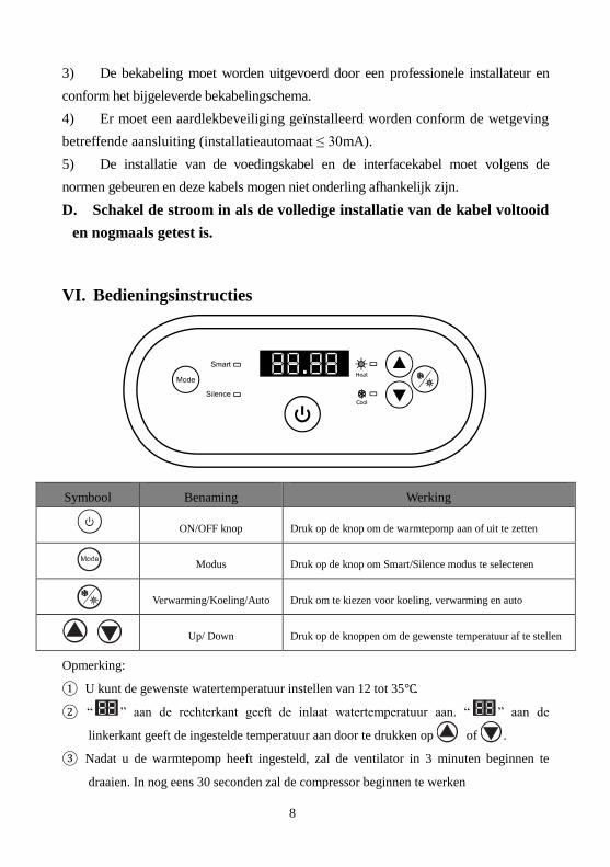
VI. Bedieningsinstructies
Symbool Benaming Werking
ON/OFF knop Druk op de knop om de warmtepomp aan of uit te zetten
Modus Druk op de knop om Smart/Silence modus te selecteren
Verwarming/Koeling/Auto Druk om te kiezen voor koeling, verwarming en auto
Up/ Down Druk op de knoppen om de gewenste temperatuur af te stellen
Opmerking:
① U kunt de gewenste watertemperatuur instellen van 12 tot 35℃.
② “ ” aan de rechterkant geeft de inlaat watertemperatuur aan. “ ” aan de
linkerkant geeft de ingestelde temperatuur aan door te drukken op of .
③ Nadat u de warmtepomp heeft ingesteld, zal de ventilator in 3 minuten beginnen te
draaien. In nog eens 30 seconden zal de compressor beginnen te werken
9
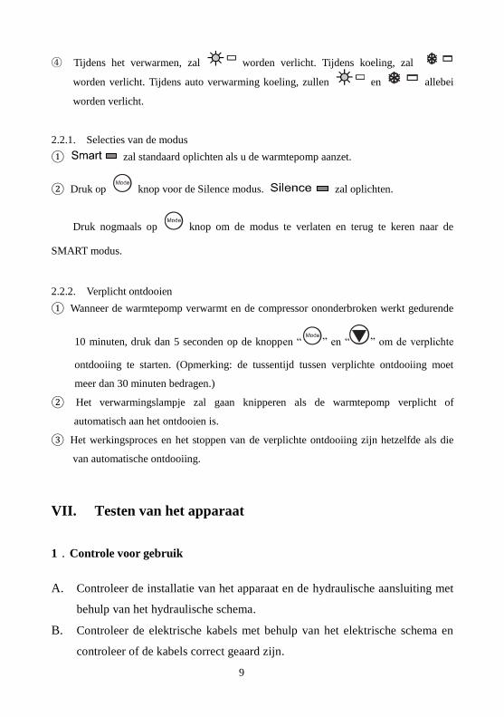
④ Tijdens het verwarmen, zal worden verlicht. Tijdens koeling, zal
worden verlicht. Tijdens auto verwarming koeling, zullen en allebei
worden verlicht.
2.2.1. Selecties van de modus
① zal standaard oplichten als u de warmtepomp aanzet.
② Druk op knop voor de Silence modus. zal oplichten.
Druk nogmaals op knop om de modus te verlaten en terug te keren naar de
SMART modus.
2.2.2. Verplicht ontdooien
① Wanneer de warmtepomp verwarmt en de compressor ononderbroken werkt gedurende
10 minuten, druk dan 5 seconden op de knoppen “ ” en “ ” om de verplichte
ontdooiing te starten. (Opmerking: de tussentijd tussen verplichte ontdooiing moet
meer dan 30 minuten bedragen.)
② Het verwarmingslampje zal gaan knipperen als de warmtepomp verplicht of
automatisch aan het ontdooien is.
③ Het werkingsproces en het stoppen van de verplichte ontdooiing zijn hetzelfde als die
van automatische ontdooiing.
VII. Testen van het apparaat
1.Controle voor gebruik
A. Controleer de installatie van het apparaat en de hydraulische aansluiting met
behulp van het hydraulische schema.
B. Controleer de elektrische kabels met behulp van het elektrische schema en
controleer of de kabels correct geaard zijn.

10
C. Verzeker u ervan dat de hoofdschakelaar op ‘off’ staat.
D. Controleer de instelling van de temperatuur.
E. Controleer of de lucht aan- en afvoer niet verstopt zijn.
2. Test
A. De gebruiker moet altijd ‘eerst de pomp en dan het apparaat aanzetten, en eerst
het apparaat en dan de pomp uitzetten’. Als dit niet in deze volgorde gebeurt,
wordt het apparaat onherstelbaar beschadigd.
B. D e gebruiker start de pomp van het zwembad en controleert of er geen
lekken zijn, vervolgens stelt hij de temperatuur in die is aangepast op
de thermostaat en schakelt de voeding in.
C. Om de verwarmingspomp voor het zwembad te beschermen, is het apparaat
voorzien van een startfunctie. Bij het starten van het apparaat slaat de blower
een minuut aan voordat de compressor aangaat.
D. Als het apparaat is gestart, controleert u of het apparaat geen abnormale
geluiden maakt.
VIII. Voorzorgsmaatregelen
1. Let op
A. Stel een comfortabele watertemperatuur in; voorkom te hoge temperaturen die
tot oververhitting leiden of te lage temperaturen waardoor het water te koud is.
B. Zorg dat er geen elementen zijn die de aan- of afvoer van de luchtcirculatie
kunnen verstoppen. Het apparaat werkt dan minder efficiënt of helemaal niet.
C. Houd uw handen niet voor de afvoer van de verwarmingspomp en raak nooit
het beschermingsrooster van de ventilator aan.
D. Als u een storing of defect constateert zoals een geluid, rook, geur of een

11
elektrisch lek, schakel dan onmiddellijk het apparaat uit en neem contact op
met een professionele installateur. Probeer nooit zelf het apparaat te
repareren.
E. Gebruik en bewaar geen gas of vloeibare brandstoffen zoals
verdun-/oplosmiddelen, verf of benzine in de nabijheid van het apparaat, dit
kan brand veroorzaken.
F. Voor optimale verwarming moeten de hydraulische leidingen tussen het
zwembad en de verwarmingspomp worden geïsoleerd. Gebruik een
passende afdekking voor het zwembad als de verwarmingspomp in werking
is.
G. Het hydraulische circuit tussen het zwembad en het apparaat moet een lengte
van ≤10 m hebben, een grotere afstand kan de efficiëntie van de verwarming
verminderen.
H. Deze serie apparaten kan een hoog efficiëntieniveau bereiken bij een
luchttemperatuur tussen +15 °C~+25 °C.
2. Veiligheid
A. De hoofdschakelaar van het apparaat moet zich buiten het bereik van kinderen
bevinden.
B. Als zich een stroomstoring voordoet en de stroom vervolgens weer wordt
ingeschakeld, zal de verwarmingspomp automatisch weer aanslaan. Zorg dat
het apparaat is uitgeschakeld bij een stroomstoring en voer een reset van de
temperatuur uit als de stroom weer is ingeschakeld.
C. Zorg dat de hoofdschakelaar van het apparaat is uitgeschakeld in geval van
onweer, zo voorkomt u eventuele bliksemschade aan het apparaat.
D. Als u het apparaat langere tijd niet gebruikt, schakel het dan uit en laat al het
water uit het apparaat lopen door de kraan van de toevoerslang open te
draaien.
12
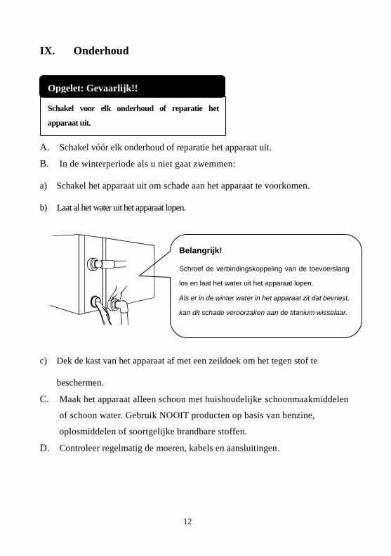
IX. Onderhoud
A. Schakel vóór elk onderhoud of reparatie het apparaat uit.
B. In de winterperiode als u niet gaat zwemmen:
a) Schakel het apparaat uit om schade aan het apparaat te voorkomen.
b) Laat al het water uit het apparaat lopen.
c) Dek de kast van het apparaat af met een zeildoek om het tegen stof te
beschermen.
C. Maak het apparaat alleen schoon met huishoudelijke schoonmaakmiddelen
of schoon water. Gebruik NOOIT producten op basis van benzine,
oplosmiddelen of soortgelijke brandbare stoffen.
D. Controleer regelmatig de moeren, kabels en aansluitingen.
Schakel voor elk onderhoud of reparatie het
apparaat uit.
Opgelet: Gevaarlijk!!
Belangrijk!
Schroef de verbindingskoppeling van de toevoerslang
los en laat het water uit het apparaat lopen.
Als er in de winter water in het apparaat zit dat bevriest,
kan dit schade veroorzaken aan de titanium wisselaar.

13
X. Probleemoplossingen voor veel voorkomende fouten
Fout Oorzaak Oplossing
De warmtepomp
functioneert niet
Geen stroom Wacht tot de stroom terugkeert
Stroomknop staat uit Zet de stroomknop aan
Zekering verbrand Controleer en vervang de zekering
De onderbreker staat uit Controleer en zet de onderbreker aan
3 minuten vertraagde start Wacht geduldig
De ventilator
functioneert maar
met onvoldoende
verwarming
Verdamper geblokkeerd Verwijder de obstakels
Lucht uitlaat geblokkeerd Verwijder de obstakels
Normale display,
maar geen
verwarming
Ingestelde temperatuur te laag Stel een juiste verwarmings- temperatuur in
3 minuten vertraagde start Wacht geduldig
Als bovenstaande oplossingen niet werken, neem dan contact op met uw installateur met gedetailleerde informatie en
uw modelnummer. Probeer het niet zelf te repareren.
Opmerking: Als u een van de volgende gevallen constateert, moet u het apparaat
onmiddellijk uitschakelen, de stroom afsluiten en contact opnemen met een
professionele installateur:
a)Een onverwachte storing
b)De zekering springt geregeld of de hoofdschakelaar slaat af.

14
Foutcode
NO. Display Geen fout beschrijving
1 E3 Geen water bescherming
2 E5 Geen fout, stroomtoevoer is hoger dat het werkingsbereik
3 E6 Excessief temperatuurverschil tussen de inlaat en uitlaat van water
(onvoldoende waterstroom bescherming)
4 Eb Omgevingstemperatuur te hoog of te laag bescherming
5 Ed Anti-vries reminder
NO. Display Foutbeschrijving
1 E1 Hoge druk bescherming
2 E2 Lage druk bescherming
3 E4 3 fase sequentie bescherming (alleen 3 fase)
4 E7 Water uitlaat temp te hoog of te laag bescherming
5 E8 Hoge uitlaat temp bescherming
6 EA Koelspiraalpijp (verdamper) oververhitting bescherming
7 P0 Controller communicatie fout
8 P1 Water inlaat temp sensor fout
9 P2 Water outlet temp sensor fout
10 P3 Gas uitlaat temp sensor fout
11 P4 Verwarming spiraalpijp (verdamper) temp sensor fout
12 P5 Gas return temp sensor fout
13 P6 Koelspiraalpijp (warmtewisselaar) temp sensor fout bij afkoelmodus
14 P7 Omgevingstemp sensor fout
15 P8 Koelplaat temp sensor failure
16 P9 Stroom sensor fout
17 PA Herstarten geheugen fout
18 F1 Module compressor drive fout
19 F2 PFC module fout
20 F3 Compressor start fout
21 F4 Compressor werking fout
22 F5 Inverter board boven stroombescherming
23 F6 Inverter board oververhitting bescherming
24 F7 Stroom bescherming
25 F8 Koelplaat oververhitting bescherming

15
26 F9 Ventilator motor fout
27 Fb Power filterplaat No-power bescherming
XI. Appendix 1: Bedradingsschema Prioriteit Verwarming (Optioneel)
Parallelle verbinding met filtratieklok
Opmerking: De installateur moet A parallel met B verbinden (zoals op de tekening hierboven). Om de
waterpomp te starten: A of B is verbonden. Om de waterpomp te stoppen zijn A en B allebei
ontbonden.
A: Waterpomp timer
B: Waterpomp bedrading van Warmtepomp
16
Garantie
In de warmtepomp VESUVIO INVERTER daar met al het materiaal en / of fabricagefouten gedurende 3 jaar garantie,
geldig vanaf de datum van levering.
De titanium warmtewisselaar is gegarandeerd tegen corrosie voor een periode van 3 jaar vanaf de datum van levering.
Schade aan de ingang en uitgang van de warmtewisselaar van de garantie in geval van een botsing of een onjuiste
behandeling kan niet worden gegarandeerd (bijvoorbeeld een verplaatsing van de warmtepomp door de in- en uitgang
connectoren).
De verslechtering van de warmtewisselaar (bijvoorbeeld een barst) in geval van niet-naleving van de winterslaap
verklaringen wordt niet gegarandeerd door ons.
Deze garantie is afhankelijk van de strikte naleving van de installatie-instructies en zorg. De garantie is ongeldig
wegens het niet voldoen aan deze voorwaarden.
De interventie onder de garantie is niet van de duur van de garantie te verlengen.
De presentatie van de aankoopfactuur strikt noodzakelijk is, indien de garantie moet worden gebruikt.
Onder deze garantie, de enige verplichting van Aqualux is de vrije uitwisseling of het product of een defecte
component die zijn gedefinieerd door een agentschap van Aqualux als fehlerhat reparatie.
Alle andere kosten worden betaald door de koper.
Om te profiteren van deze garantie, moet het product bij voorbaat voor de Aqualux klantenservice, zijn toestemming
voor de eventuele vervanging onontbeerlijk.
Wettelijke garantie: Als de koper maakt het bewijs van verborgen gebrek, moet de verkoper aansprakelijk voor
eventuele juridische consequenties (artikel 1641 van het Burgerlijk Wetboek) zijn.
Indien de koper gaat naar de rechter, moet dit gebeuren binnen een korte tijd na de ontdekking van het verborgen
gebrek (artikel 1648 van het Burgerlijk Wetboek).
ECO DEELNAME (AEEA-richtlijn)
Volgens mitder Europese Richtlijn 2002/96 / EGundzur het bereiken van een rij vonUmweltzielen, moeten volgende
Regelnangewandt zijn.
Ze verwijzen aufelektrische en elektronische apparatuur (AEEA).
De aangebracht op onze producten betekent dat de Notwedigkeit gescheiden inzameling en sortering van huishoudelijk
restafval.
De consument moet dit product te dienen voor verwijdering aan een verzameling stortplaats.
Doordat de recycling van het product de consument bij aan de bescherming van het milieu
287 Ave de la Massane – 13210 SAINT REMY DE PROVENCE – France
[email protected] / www.aqualux.com

MANUAL DE USUARIO E
INSTALACIÓN
FR / EN / DE / NL / ESP
Bomba de calor de la piscina del inversor

Contenido
I. Uso ........................................................................................................... 1
II. Características .......................................................................................... 1
III. Parámetros técnicos.................................................................................. 2
IV. Dimensión ................................................................................................ 3
V. Instrucciones de instalación ..................................................................... 4
VI. Instrucciones de uso ................................................................................. 7
VII. Verificación .............................................................................................. 8
VIII. Precauciones ............................................................................................ 9
IX. Mantenimiento ....................................................................................... 11
X. Solución de problemas para averías comunes ........................................ 12
XI. Apéndice 1: Diagrama de cableado de prioridad del calentamiento (opcional) ...... 14
Gracias por elegir nuestro producto y confiar en nuestra empresa. Para disfrutar
al máximo de este producto, léase el manual de instrucciones cuidadosamente
y siga el manual del usuario antes de activar el equipo; de lo contrario, podría
dañar el equipo o a ud. mismo de forma innecesaria.
I. Uso
1- Configure la temperatura del agua de la piscina de forma eficiente y
económica, adaptándose a su comodidad y gusto.
2- El usuario puede elegir el parámetro técnico con la ayuda de la guía
profesional; esta serie de calentador de piscina ha sido optimizada en
fábrica (véase la tabla de parámetros técnicos).
II. Características
1- Intercambiador de calor de titanio de alto rendimiento.
2- Control y visualizador de temperatura del agua sensibles y exactos.
3- Protección de presión alta y baja.
4- Protección con paro automático en caso de superar la temperatura baja.
5- Control de temperatura con descongelamiento obligatorio.
6- Compresor de marca internacional.
7- Fácil de instalar y usar.

III. Parámetros técnicos
Modelo VESIN08N VESIN10N VESIN13N VESIN17N VESIN21N
Volumen recomendado de la
piscina (m3)
20~40 30~50 40~70 55-85 70-100
Temperatura de funcionamiento del
aire (℃)
0~43
Condición de rendimiento: Aire 26°C, Agua 26°C, Humedad 80%
Capacidad de calentamiento (kW) 8.0 9.2 12.5 16.5 20.5
C.O.P. 10.8~5.6 11.2~5.5 12.0~5.6 11.8~5.5 12.0~5.6
C.O.P op 50% capaciteit 8.2 8.6 9.5 9.1 9.2
Condición de rendimiento: Aire 15°C, Agua 26°C, Humedad 70%
Capacidad de calentamiento (kW) 6.0 7.0 9.0 11.5 14.0
C.O.P. 6.7~3.9 6.6 - 3.8 6.7 - 3.9 6.7 - 3.8 6.7 - 3.9
C.O.P op 50% capaciteit 6.1 5.8 6.0 6.2 5.9
Potencia nominal de entrada
En el aire 15 ° C (kW)
0.19 - 1.3 0.21 - 1.7 0.3 - 2.3 0.36 - 2.9 0.45 - 3.7
Corriente nominal de entrada
En el aire 15 ° C (A)
0.83 - 5.6 0.91 - 7.4 1.3 - 10 1.6 - 12.6 1.96 - 16.1
Corriente máxima de entrada (A) 7.5 9.0 11.0 15.0 18.5
Fuente de alimentación 220 - 240V/1 Ph/50Hz
Flujo de agua aconsejado (m³/h) 2~4 3~4 4~6 6~8 8~10
Presión acústica 10m dB(A) 20.5~29.2 21.3~30 21.5~30.2 24.8~34.1 26.2~34.9
Tubo de agua in-out Spec (mm) 50
Dimensión neta LxWxH (mm) 864×349×648 864×349×648 864×349×648 954×349×648 954×349×748
Peso neto (kg) 46 47 49 60 63
Nota:
1. Este producto puede trabajar bien bajo temperatura del aire 0°C~43°C; El
rendimiento no se puede garantizar fuera de los rangos de operación y se deben tomar
en cuenta las condiciones exteriores de uso identificadas para seleccionar el modo
adecuado (tal como ubicación, zona de la piscina, y el número de bañadores)
2. Los parámetros anteriores están sujetos a ajustes periódicos para una mejora de la técnica

con aviso posterior. Por favor, consulte la placa de características en cada máquina para
obtener información precisa.
IV. Dimensión
※Los datos anteriores están sujetos a modificación sin previo aviso
Nota:
La imagen de arriba es el diagrama de especificaciones del calentador de la
piscina, para la instalación del técnico y la referencia de diseño solamente. El
producto está sujeto a ajustes periódicos para mejorar sin previo aviso.
A B C D E F G H
VESIN08N 324 560 330 349 872 250 74 654
VESIN10N 324 560 330 349 872 250 74 654
VESIN13N 324 560 330 349 872 290 74 654
VESIN17N 324 590 330 349 962 350 74 654
VESIN21N 324 590 325 349 962 350 74 754
Nombre Tamaño (mm)
Modelo

V. Instrucciones de instalación
1. Diagrama para conexión de tuberías de agua
(aviso:este diagrama es solo explicativo, el diseño de tuberías solo vale como referencia.)
2. Diagrama de Cableado Eléctrico
Nota: 1) Conexión de cable, sin enchufe.
2) La bomba de calor ha de estar conectada a tierra.

Opciones para proteger los dispositivos y especificación de cables
※ Los datos mencionados pueden estar sometidos a modificaciones sin aviso previo.
Nota: Los datos mencionados corresponden a una longitud de cable eléctrico ≤ 10 m. Si el
cable es﹥10 m, se requiere aumentar el diámetro del cable. El cable de señal se puede
extender hasta un máximo de 50 m.
3. Instrucciones y requisitos de instalación
La bomba de calor debe ser instalada por profesionales. Los usuarios no están
cualificados para efectuar la instalación ellos mismos y la bomba de calor
podría resultar dañada con el riesgo consiguiente para la seguridad de los
usuarios.
A. Aviso antes de la instalación
1) Las conexiones de agua de entrada y salida no pueden soportar el peso de
tuberías blandas. ¡La bomba de calor debe conectarse con tuberías rígidas!
2) Con el fin de garantizar la eficacia del calentamiento, la longitud de la
tubería de agua entre la piscina y la bomba de calor debe ser ≤10 m.
MODELO VESIN08N VESIN10N VESIN13N VESIN17N VESIN21N
Disyuntor
Corriente
nominal A 9.0 11.0 13.5 18.0 22.0
Corriente
residual
nominal
mA
30 30 30 30 30
Fusible A 9.0 11.0 13.5 18.0 22.0
Cable de corriente
(mm2)
3×1.5 3×2.5 3×2.5 3×2.5 3×4
Cable de señal
(mm2)
3×0.5 3×0.5 3×0.5 3×0.5 3×0.5

B. Instrucciones para la instalación
1) Ubicación y tamaño
La bomba de calor debe instalarse en un lugar con buena ventilación.
2) Sujete el armazón a la base de hormigón u a los soportes con tornillos
(M10). Sujete la base de hormigón de forma sólida. Trate el soporte con
un fuerte antioxidante.
3) No acumule sustancias que puedan obstruir el flujo de aire cerca de una
zona de entrada o salida. No coloque ninguna valla a una distancia menor
de 50 cm detrás del dispositivo principal, ya que podría reducir la
eficiencia o incluso parar el funcionamiento de la bomba de calor.
4) El dispositivo requiere una bomba de agua adicional (facilitada por el
usuario). Para consultar el flujo de bomba recomendado, véase los
parámetros técnicos; elevación máxima ≥10m.
5) Durante el funcionamiento del dispositivo, compruebe que no se escape
agua condensada de la parte de abajo. Mantenga la boquilla de drenaje
(accesorio) en el agujero y sujétela bien antes de conectar una tubería para
vaciar el agua condensada.
* Distancia mínima
Filtro
Procesador de agua
Interruptor de agua

C.Cableado
1) Haga la conexión al suministro de energía apropiado. El voltaje ha de
cumplir con el voltaje nominal de los productos.
2) Conecte el dispositivo a tierra.
3) Un técnico profesional se encargará de la instalación del cableado,
conforme al diagrama del circuito.
4) Instale el protector de escape según la normativa local para cableados
(corriente de fuga ≤ 30mA).
5) Coloque el cable de corriente y el cable de señal de forma correcta para
que no se afecten el uno al otro.
D.Después de instalar todo el cableado, encienda y vuelva a comprobar.
VI. Instrucciones de uso
Nota:
① Usted puede ajustar la temperatura del agua que desee entre 12 y 35℃.
② " " a la derecha muestra la temperatura del agua de entrada. " " a la
izquierda muestra la temperatura ajustada pulsando o .
③ Cuando haya encendido la bomba de calor, el ventilador entrará en
funcionamiento al cabo de 3 minutos. Al cabo de otros 30 segundos, el
compresor se pondrá en funcionamiento.
④ Durante el calentamiento, se iluminará. Durante el enfriamiento,
se iluminará. Duante auto calentamiento enfriamiento, y
se iluminarán.

2.2.1. Selecciones de modo
① se iluminará de manera predeterminada cuando usted encienda
la bomba de calor.
② Pulse el botón para introducir el modo Silencioso, se
iluminará.
Pulse de nuevo el botón para salir del modo Silencioso e introducir
el modo INTELIGENTE.
2.2.2. Descongelación obligatoria
① Cuando la bomba de calor está calentando y el compresor haya estado en
funcionamiento de manera continua durante 10 minutos, pulse los
botones " "y " " durante 5 segundos para iniciar la descongelación
obligatoria. (Nota: el intervalo entre la descongelación obligatoria debería
ser de más de 30 minutos.)
② La luz de calentamiento parpadeará cuando la bomba de calor esté en
descongelación obligatoria o automática.
③ El proceso de ejecución y la finalización de la descongelación obligatoria
son los mismos que los de la descongelación automática.
VII. Verificación
1.Inspección antes del uso
A. Compruebe la instalación de toda la máquina y las conexiones de tubería
de acuerdo con el esquema de conexión del tubo;
B. Compruebe el cableado eléctrico de acuerdo con el diagrama de cableado
eléctrico y la conexión a tierra;
C. Asegúrese de que el interruptor principal de la máquina esté apagado;
D. D. Compruebe el ajuste de la temperatura;

E. Compruebe la entrada y salida de aire.
2.Verificación
A. Encienda la bomba antes del equipo, y apague el equipo antes de la
bomba; de lo contrario, se dañará el equipo;
B. Enciende la bomba y compruebe que no hay ningún escape de agua; luego,
ajuste la temperatura adecuada en el termóstato, y encienda el suministro
de corriente;
C. Para proteger la bomba de calor, el dispositivo viene equipado con una
función de encendido con intervalo; al encenderse el dispositivo, el
calefactor se activa 1 minuto antes del compresor;
D. Una vez que se haya encendida la bomba de calor, compruebe que el
dispositivo no emita ruidos anómalos.
VIII. Precauciones
1. Atención
A. Configure una temperatura de agua para evitar un calor o un frío
excesivos;
B. No acumule sustancias que podrían obstruir el flujo de aire cerca de una
zona de entrada o salida, ya que podría reducir la eficiencia o incluso
parar el funcionamiento del calentador.
C. No coloque las manos el la salida de la bomba de calor y no quite la rejilla
del ventilador en ningún momento;
D. En el caso de anomalías como ruido, olor, humo y escape, apague el
dispositivo inmediatamente y póngase en contacto con su suministrador
local. No intente repararlo solo;
E. Para evitar riesgos de incendios, no utilice o almacene gas o líquidos
combustibles (disolventes, pintura, carburante);
F. Para optimizar el efecto de la calefacción, instale un aislamiento para
conservar el calor en las tuberías entre la piscina y el calentador. Durante
el funcionamiento del calentador, utilice una cubierta recomendada para
proteger la piscina.

G. La longitud de las tuberías de conexión entre la piscina y la bomba de
calor deben de ser ≤10m; de lo contrario, no se puede garantizar el
rendimiento del equipo.
H. Este serie de dispositivos es altamente eficiente con temperaturas de aire
de +15℃~+25℃.
2. Seguridad
A. Mantenga el interruptor de corriente principal fuera del alcance de los
niños;
B. En el caso de que ocurriera un corte de electricidad durante el
funcionamiento, la bomba de calor se encenderá automáticamente una vez
que se haya restablecido la electricidad. Apague el suministro de corriente
y vuelva a configurar la temperatura una vez que se haya restablecido la
corriente;
C. En el caso de relámpagos o temporal, apague el suministro de corriente
principal para evitar que los relámpagos dañen el equipo;
D. Si no se utiliza el equipo durante un tiempo largo, corte el suministro de
corriente y abra el tapón de las tuberías de entrada para vaciar el agua del
equipo.

IX. Mantenimiento
A. En temporada de invierno cuando no hayan bañadores:
1. Corte el suministro de energía para evitar cualquier daño a la
máquina
2. Vacíe el agua y limpie la máquina.
3. Cubre la máquina cuando no esté en uso.
B. Por favor limpiar la máquina con detergentes de uso doméstico o agua
limpia, NUNCA utilice gasolina, disolventes o cualquier combustible
similar.
C. Compruebe pernos, cables y conexiones con regularidad.
“Apague” la fuente de alimentación del calentador antes de
realizar labores de limpieza, inspección y reparación.
Precaución: Peligro de descarga eléctrica
!!Importante:
Desenrosque la boquilla de agua del tubo de entrada para
permitir la salida del agua.
Cuando el agua en la máquina se congele en la temporada de
invierno, el intercambiador de calor de titanio se puede dañar.

X. Solución de problemas para averías comunes
Fallo Causa Solución
La bomba de calor no entra
en funcionamiento
No hay alimentación eléctrica Espere a que se restaure la
alimentación eléctrica
El interruptor de alimentación está
apagado Encienda la alimentación
Fusible fundido Compruebe y cambie el fusible
El disyuntor está desconectado Inspeccione y conecte el disyuntor
Retardo del arranque de 3 minutos Tenga paciencia
El ventilador está en
funcionamiento pero el
calentamiento es insuficiente
Evaporador bloqueado Retire los obstáculos
Salida de aire bloqueada Retire los obstáculos
Visualización normal, pero
no hay calentamiento
Ajuste de la temp. demasiado bajo Ajuste la temp. de calentamiento
apropiada
Retardo del arranque de 3 minutos Tenga paciencia
Si las soluciones arriba indicadas no funcionan, póngase en contacto con su instalador indicándole información
detallada del fallo y el número de modelo. No intente reparar la bomba de calor usted mismo.
Nota: Si ocurren los casos siguientes, pare el dispositivo inmediatamente, apague el
interruptor manual de suministro de corriente y póngase en contacto con su distribuidor
local.
a)Encendido o apagado inexacto;
b)El fusible se estropea o el interruptor diferencial de fuga salta con frecuencia.
Código de error
Nº Visualización Descripción del no es un fallo
1 E3 Protección contra la falta de agua
2 E5 La alimentación sobrepasa el rango de funcionamiento
3 E6 Diferencia de temp. excesiva entre el agua de entrada y salida
(protección contra flujo de agua insuficiente)
4 Eb Protección contra temp. ambiente demasiado alta o baja
5 Ed Recordatorio anticongelación

Nº Visualización Descripción del fallo
1 E1 Protección de alta presión
2 E2 Protección de baja presión
3 E4 Protección de secuencia trifásica (solo trifásica)
4 E7 Protección contra temp. de salida del agua demasiado alta o baja
5 E8 Protección de temp. de escape alta
6 EA Protección contra el sobrecalentamiento de la tubería del serpentín de
refrigeración (evaporador)
7 P0 Fallo de la comunicación del controlador
8 P1 Fallo del sensor de temp. de entrada de agua
9 P2 Fallo del sensor de temp. de salida de agua
10 P3 Fallo del sensor de temp. de gas de escape
11 P4 Fallo del sensor de temp. de la tubería del serpentín de calentamiento
(evaporador)
12 P5 Fallo del sensor de temp. de gas de retorno
13 P6 Fallo del sensor de temp. de la tubería del serpentín de refrigeración
(intercambiador de calor) en el modo de refrigeración
14 P7 Fallo del sensor de temp. ambiente
15 P8 Fallo del sensor de temp. de placa de refrigeración
16 P9 Fallo del sensor de corriente
17 PA Fallo de reinicio de la memoria
18 F1 Fallo del módulo de accionamiento del compresor
19 F2 Fallo del módulo PFC
20 F3 Fallo de arranque del compresor
21 F4 Fallo de funcionamiento del compresor
22 F5 Protección contra sobrecorriente de la placa del inversor
23 F6 Protección contra sobrecalentamiento de la placa del inversor
24 F7 Protección de corriente
25 F8 Protección contra sobrecalentamiento de la placa de refrigeración
26 F9 Fallo del motor del ventilador
27 Fb Protección c87ontra falta de alimentación y placa de filtro

XI. Apéndice 1: Diagrama de cableado de prioridad del calentamiento (opcional)
Conexión en paralelo con reloj de filtración
B: Cableado de la bomba de agua de la Bomba de Calor
Nota: El instalador debe conectar A en paralelo con B (como en la imagen de arriba) Para
poner la bomba de agua en marcha, A o B debe estar conectado. Para detener la
bomba de agua, A y B deben estar desconectados.
A: Temporizador de la bomba de agua

Garantía:
La bomba de calor VESUVIO INVERTER está garantizada contra cualquier defecto de materia y/o de fabricación durante una duración de
dos 3 años a partir de la fecha de entrega.
El intercambiador de titanio es garantizado contra la corrosión por un período de 5 años a partir de la fecha de entrega.
El destrozo de las entradas o salidas del intercambiador no está cubierto por la garantía en caso de impacto o en caso de manipulación no
adecuada (levantar la pompa de calor por las entradas-salidas).
El deterioro del intercambiador en caso de incumplimiento de las consignas de invernada no es cubierto por la garantía.
Esta garantía está condicionada al estricto respeto del manual de montaje y/o de mantenimiento. La garantía no se aplicará en caso de no
respeto de estas condiciones.
Ninguna garantía se puede validar a falta del pago íntegro.
Las intervenciones a título de la garantía no pueden tener como efecto prolongar la duración de ésta.
La presentación de la factura de compra será rigurosamente exigida cuando se invoque la garantía.
A título de esta garantía, la única obligación que incumbe a AQUALUX será, a elección de AQUALUX, el reemplazo gratuito o la
reparación en taller del producto o del elemento reconocido como defectuoso por los servicios de AQUALUX. Todos los otros gastos
estarán a cargo del comprador.
Para beneficiarse de esta, todo producto debe presentarse de antemano al servicio postventa de AQUALUX, cuyo acuerdo es indispensable
para cualquier sustitución o reparación en taller.
La garantía no se aplica en caso de defecto aparente. También se excluyen los defectos y deterioros causados por el desgaste normal, los
defectos que resulten de un montaje y/o de un empleo no conformes, y las modificaciones del producto realizadas sin el consentimiento
escrito y previo de AQUALUX.
Garantía legal: A condición de que el comprador aporte la prueba del defecto oculto, el vendedor debe legalmente reparar todas
las consecuencias (artículo 1641 y siguientes del Código civil francés).
Si el comprador se dirige a los tribunales, debe hacerlo en un plazo breve a partir del descubrimiento del vicio oculto (artículo
1648 del Código civil francés).
ECO PARTICIPACIÓN (Directiva DEEE)
De acuerdo con la Directiva Europea 2002/96/CE, y con el fin de lograr una serie de objetivos en cuanto a la protección del medio
ambiente, deben aplicarse las siguientes normas.
Se refieren a los desechos de equipos eléctricos y electrónicos (DEEE).
El pictograma de al lado presente en el producto, su manual de utilización o su embalaje indica que el producto está
sometido a esta reglamentación. El consumidor debe llevar el producto usado a los puntos de recogida previstos a
tal efecto.
Al permitir el reciclaje de los productos, el consumidor contribuirá a la protección de nuestro medio ambiente. Es
un acto ecológico.
287 Ave de la Massane – 13210 SAINT REMY DE PROVENCE – France
[email protected] / www.aqualux.com


Version: A19ING