Embed Size (px)
Citation preview
Defining the Next Generation of the IP‐Connected Enterprise:
A Practitioner’s Guide to Best PracticesProudly presented by:
Andy Jimenez | ANIXTER INC.
Your Presenter
• Andy Jimenez– Vice President, Technology, Enterprise
Cabling and Security Solutions, Anixter– Over 20 years experience in telecommunications
testing and product verification– Leads standards development and
product testing at Anixter’s Infrastructure Solutions LabSM
– Active voting member of TIA TR‐42.7 cabling and IEEE 802.3 LAN/MAN standards committees
– Cisco CCNA with Wireless Specialization
Agenda
• Market trends– IoT defined– Impact on physical infrastructure systems
• IoT applications– Building technologies– Physical security– Data centers
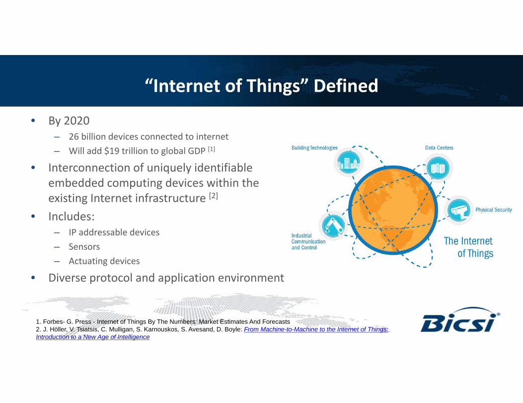
“Internet of Things” Defined
• By 2020– 26 billion devices connected to internet– Will add $19 trillion to global GDP [1]
• Interconnection of uniquely identifiable embedded computing devices within the existing Internet infrastructure [2]
• Includes: – IP addressable devices– Sensors– Actuating devices
• Diverse protocol and application environment
1. Forbes- G. Press - Internet of Things By The Numbers: Market Estimates And Forecasts2. J. Höller, V. Tsiatsis, C. Mulligan, S. Karnouskos, S. Avesand, D. Boyle: From Machine-to-Machine to the Internet of Things: Introduction to a New Age of Intelligence
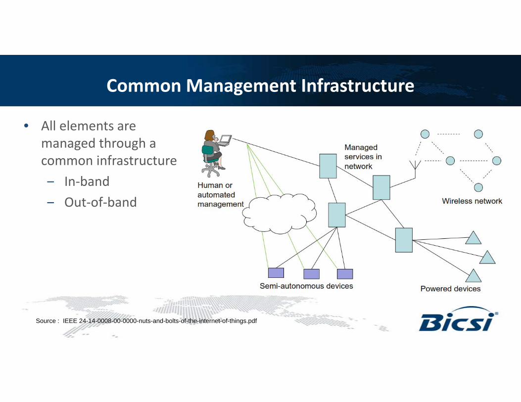
Common Management Infrastructure
• All elements are managed through a common infrastructure‒ In‐band ‒ Out‐of‐band
Source : IEEE 24-14-0008-00-0000-nuts-and-bolts-of-the-internet-of-things.pdf
Challenges
• Device management• Heterogeneous protocol environment• Standards development
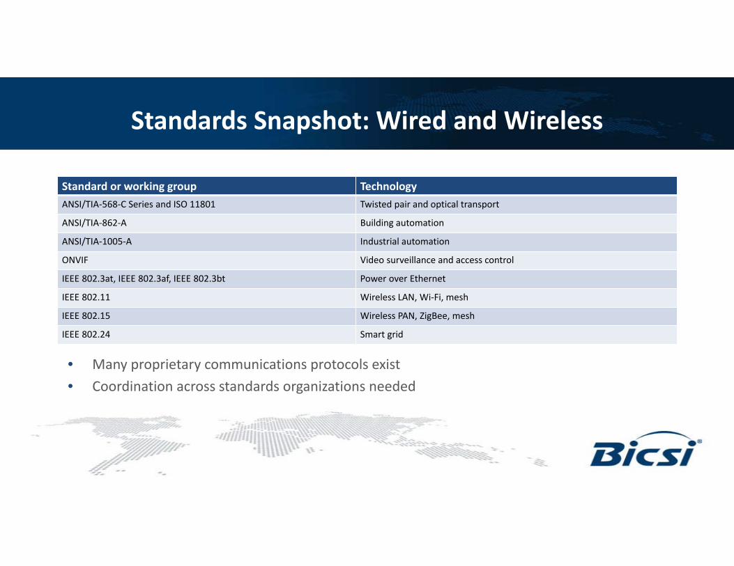
Standards Snapshot: Wired and Wireless
Standard or working group TechnologyANSI/TIA‐568‐C Series and ISO 11801 Twisted pair and optical transport
ANSI/TIA‐862‐A Building automation
ANSI/TIA‐1005‐A Industrial automation
ONVIF Video surveillance and access control
IEEE 802.3at, IEEE 802.3af, IEEE 802.3bt Power over Ethernet
IEEE 802.11 Wireless LAN, Wi‐Fi, mesh
IEEE 802.15 Wireless PAN, ZigBee, mesh
IEEE 802.24 Smart grid
• Many proprietary communications protocols exist• Coordination across standards organizations needed
IoT Standardization Efforts
BUILDING TECHNOLOGIES
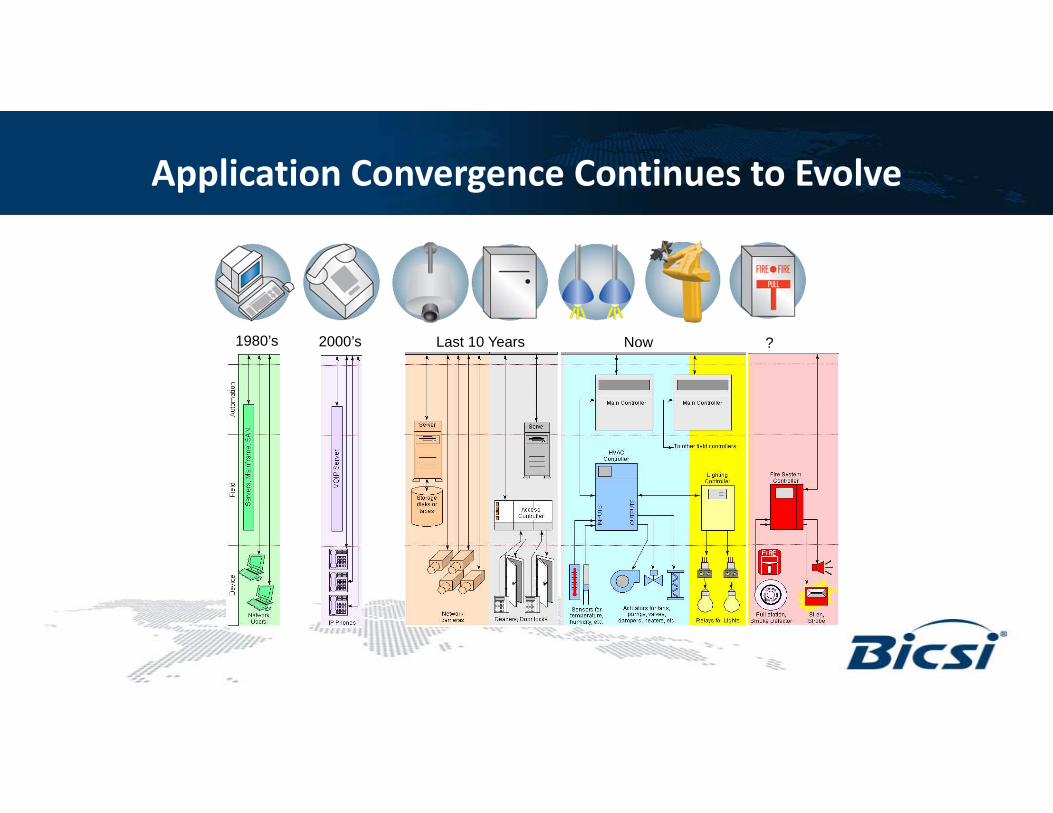
Application Convergence Continues to Evolve
1980’s 2000’s Last 10 Years Now ?
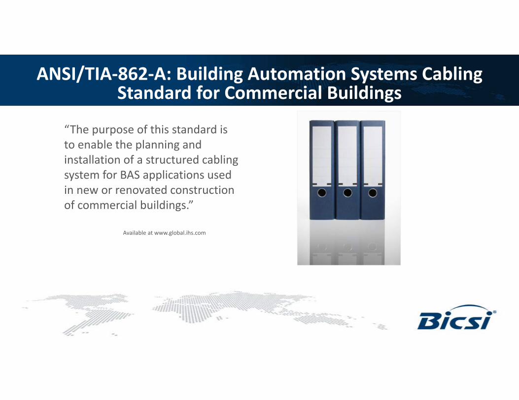
ANSI/TIA‐862‐A: Building Automation Systems Cabling Standard for Commercial Buildings
“The purpose of this standard is to enable the planning and installation of a structured cabling system for BAS applications used in new or renovated construction of commercial buildings.”
Available at www.global.ihs.com
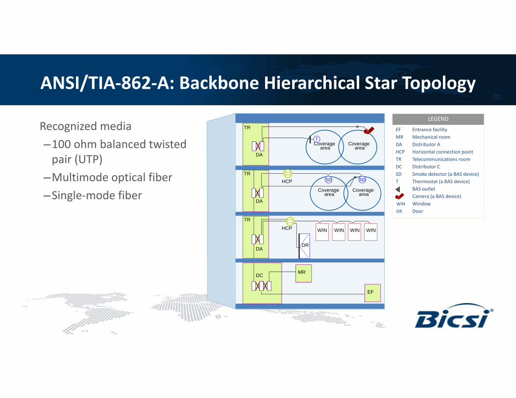
ANSI/TIA‐862‐A: Backbone Hierarchical Star Topology
TR
TR
TR
DC
DA
DA
DA
HCP
HCP
Coverage area
Coverage area
Coverage area
Coverage area
T
SD SD
MR
EF
WIN WIN WIN WIN
DR
Recognized media–100 ohm balanced twisted pair (UTP)
–Multimode optical fiber–Single‐mode fiber
Entrance facilityMechanical roomDistributor AHorizontal connection pointTelecommunications roomDistributor CSmoke detector (a BAS device)Thermostat (a BAS device)BAS outletCamera (a BAS device)WindowDoor
LEGEND
EFMRDAHCPTRDCSDT
WINDR
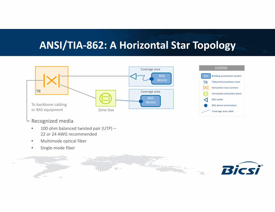
ANSI/TIA‐862: A Horizontal Star Topology
TR
BAS device
BAS device
Coverage area
Coverage area
LEGEND
Building automation system
Telecommunications room
Horizontal cross‐connect
Horizontal connection point
BAS outlet
BAS device termination
Coverage area cable
BAS
TR
Zone box
Recognized media • 100 ohm balanced twisted pair (UTP) –
22 or 24 AWG recommended• Multimode optical fiber• Single‐mode fiber
To backbone cabling or BAS equipment
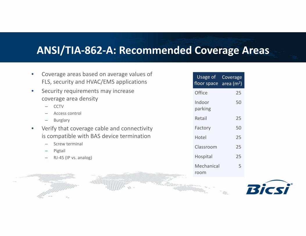
ANSI/TIA‐862‐A: Recommended Coverage Areas
• Coverage areas based on average values of FLS, security and HVAC/EMS applications
• Security requirements may increase coverage area density
– CCTV– Access control– Burglary
• Verify that coverage cable and connectivity is compatible with BAS device termination
– Screw terminal– Pigtail– RJ‐45 (IP vs. analog)
Usage of floor space
Coverage area (m2)
Office 25
Indoor 50parking
Retail 25
Factory 50
Hotel 25
Classroom 25
Hospital 25
Mechanical 5 room
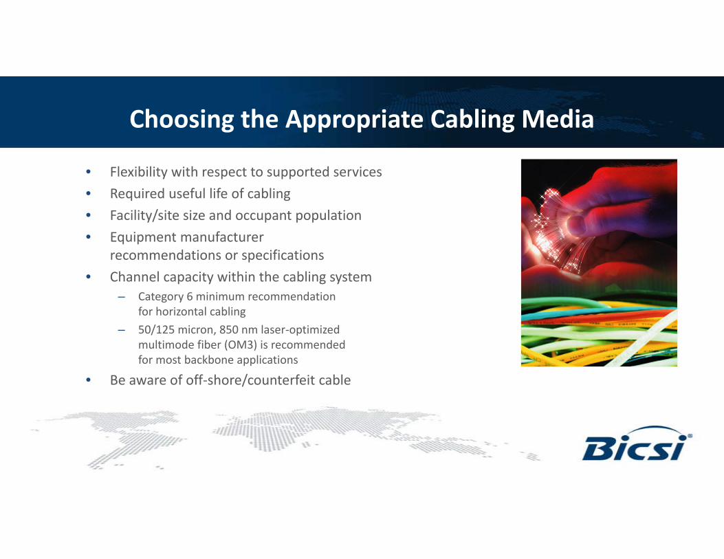
Choosing the Appropriate Cabling Media
• Flexibility with respect to supported services• Required useful life of cabling• Facility/site size and occupant population• Equipment manufacturer
recommendations or specifications• Channel capacity within the cabling system
– Category 6 minimum recommendation for horizontal cabling
– 50/125 micron, 850 nm laser‐optimized multimode fiber (OM3) is recommended for most backbone applications
• Be aware of off‐shore/counterfeit cable
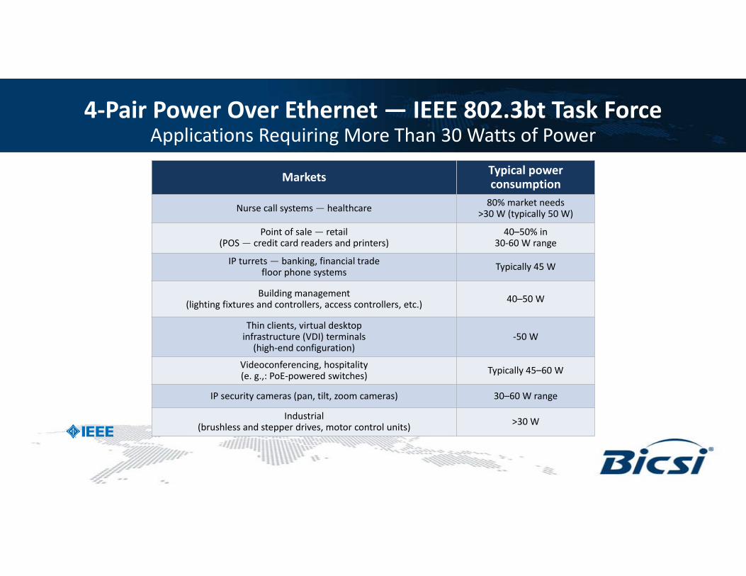
4‐Pair Power Over Ethernet — IEEE 802.3bt Task ForceApplications Requiring More Than 30 Watts of Power
Markets Typical power consumption
Nurse call systems — healthcare 80% market needs >30 W (typically 50 W)
Point of sale — retail(POS — credit card readers and printers)
40–50% in 30‐60 W range
IP turrets — banking, financial trade floor phone systems Typically 45 W
Building management(lighting fixtures and controllers, access controllers, etc.) 40–50 W
Thin clients, virtual desktop infrastructure (VDI) terminals
(high‐end configuration)‐50 W
Videoconferencing, hospitality (e. g.,: PoE‐powered switches) Typically 45–60 W
IP security cameras (pan, tilt, zoom cameras) 30–60 W range
Industrial(brushless and stepper drives, motor control units) >30 W
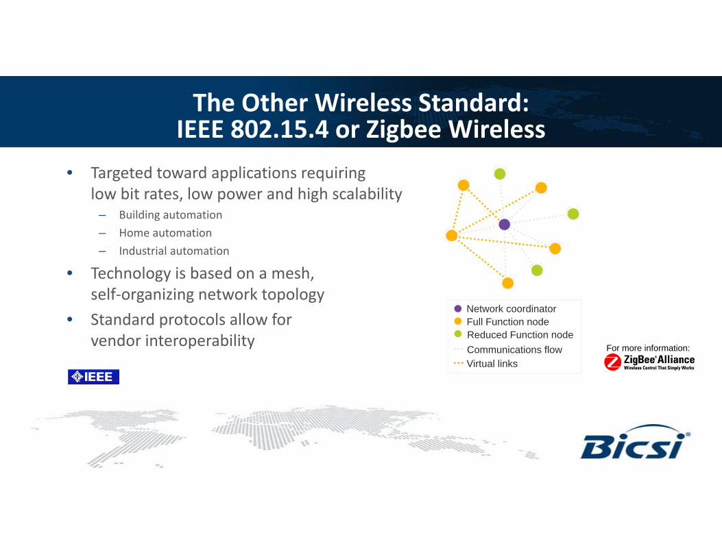
The Other Wireless Standard: IEEE 802.15.4 or Zigbee Wireless
• Targeted toward applications requiring low bit rates, low power and high scalability
– Building automation– Home automation– Industrial automation
• Technology is based on a mesh, self‐organizing network topology
• Standard protocols allow for vendor interoperability
Network coordinatorFull Function nodeReduced Function nodeCommunications flowVirtual links
For more information:
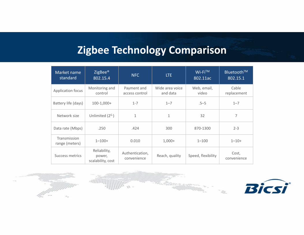
Zigbee Technology Comparison
Market namestandard
ZigBee®802.15.4
NFC LTEWi‐FiTM
802.11acBluetoothTM
802.15.1
Application focus Monitoring and control
Payment and access control
Wide area voice and data
Web, email, video
Cable replacement
Battery life (days) 100‐1,000+ 1‐7 1–7 .5–5 1–7
Network size Unlimited (2G.) 1 1 32 7
Data rate (Mbps) .250 .424 300 870‐1300 2‐3
Transmission range (meters) 1–100+ 0.010 1,000+ 1–100 1–10+
Success metricsReliability, power,
scalability, cost
Authentication, convenience Reach, quality Speed, flexibility Cost,
convenience
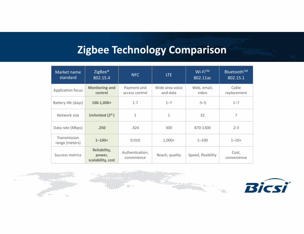
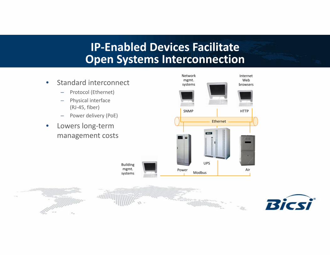
IP‐Enabled Devices Facilitate Open Systems Interconnection
• Standard interconnect– Protocol (Ethernet)– Physical interface
(RJ‐45, fiber)– Power delivery (PoE)
• Lowers long‐term management costs
UPS
Networkmgmt.systems
Internet Web
browsers
SNMP HTTP
Ethernet
ModbusPower Air
Buildingmgmt.systems
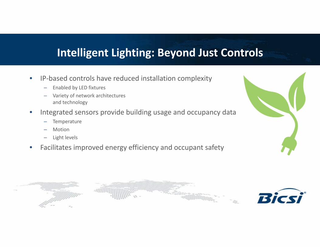
Intelligent Lighting: Beyond Just Controls
• IP‐based controls have reduced installation complexity– Enabled by LED fixtures– Variety of network architectures
and technology
• Integrated sensors provide building usage and occupancy data– Temperature– Motion– Light levels
• Facilitates improved energy efficiency and occupant safety
Intelligent Lighting Systems
PHYSICAL SECURITY
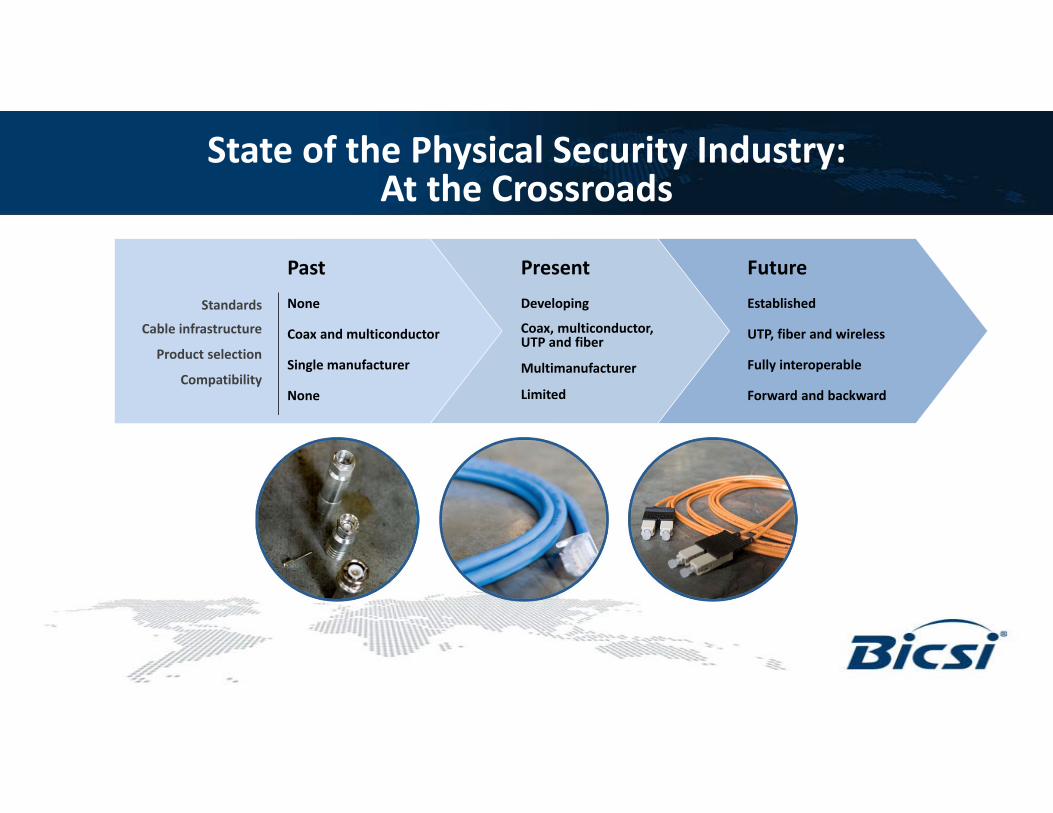
State of the Physical Security Industry: At the Crossroads
FutureEstablished
UTP, fiber and wireless
Fully interoperable
Forward and backward
PresentDeveloping
Coax, multiconductor, UTP and fiber
Multimanufacturer
Limited
Standards
Cable infrastructure
Product selection
Compatibility
PastNone
Coax and multiconductor
Single manufacturer
None
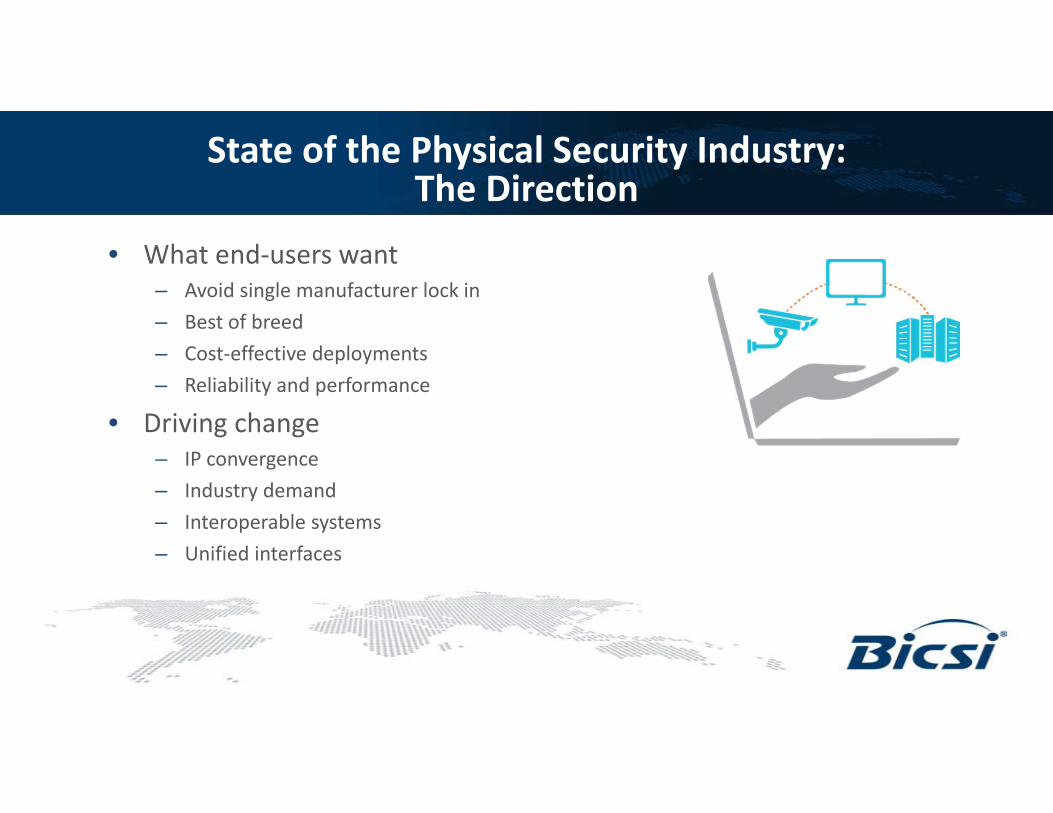
State of the Physical Security Industry:The Direction
• What end‐users want– Avoid single manufacturer lock in– Best of breed– Cost‐effective deployments– Reliability and performance
• Driving change– IP convergence– Industry demand– Interoperable systems– Unified interfaces
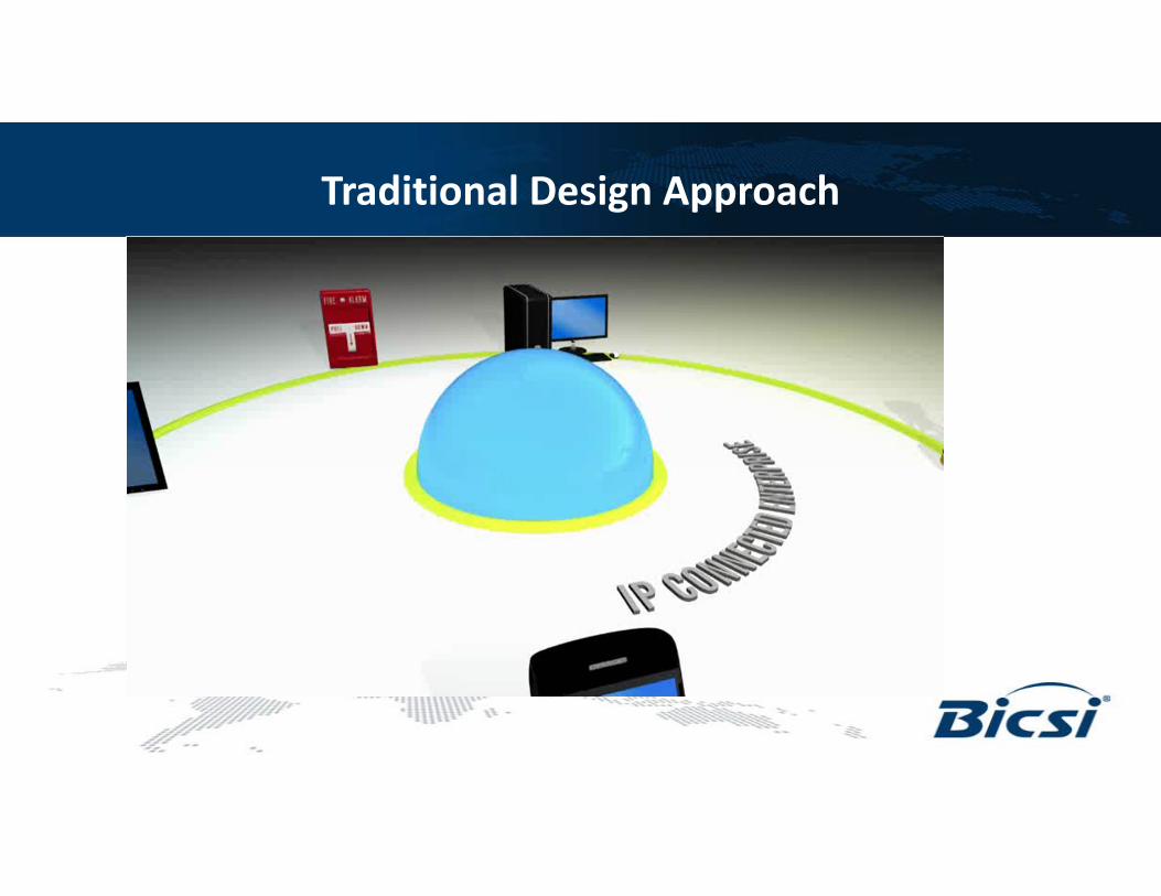
Traditional Design Approach
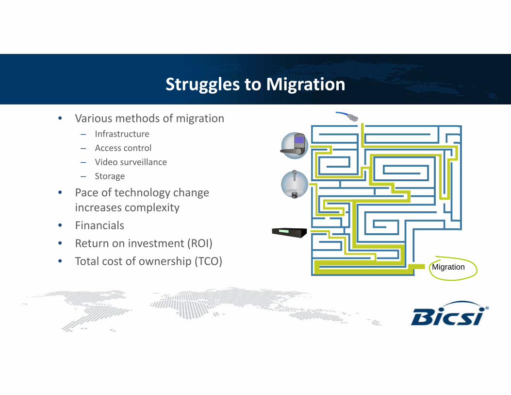
Struggles to Migration
• Various methods of migration– Infrastructure– Access control– Video surveillance– Storage
• Pace of technology change increases complexity
• Financials• Return on investment (ROI)• Total cost of ownership (TCO) Migration
Organizations Driving Standardization
• Security Industry Association (SIA)–Open Systems Integration and Performance Standards (OSIPS)
–Access control and digital video interface–ANSI accredited
• Physical Security Interoperability Alliance (PSIA)–Manufacturers: 80+–Products: 100+–Working groups: IP video, video analytics, recording and content management, access control and systems
• Open Network Video Interface Forum (ONVIF)–Manufacturers: 310+–Products: 915+–Working groups: network video and physical access control
Organizations Driving Standardization (continued)
• Open Network Video Interface Forum (ONVIF) (continued)
• To facilitate the development of a global open standard
• Standardize communication between IP‐based physical security devices
• Ensure interoperability • Open to all companies
Open Network Video Interface Forum (ONVIF)
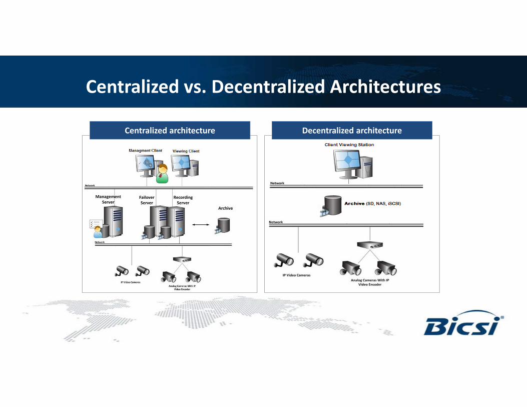
Centralized vs. Decentralized Architectures
Centralized architecture Decentralized architecture
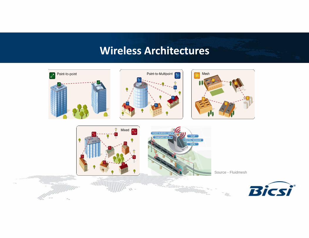
Wireless Architectures
Source - Fluidmesh
Video Surveillance Camera as a Sensor
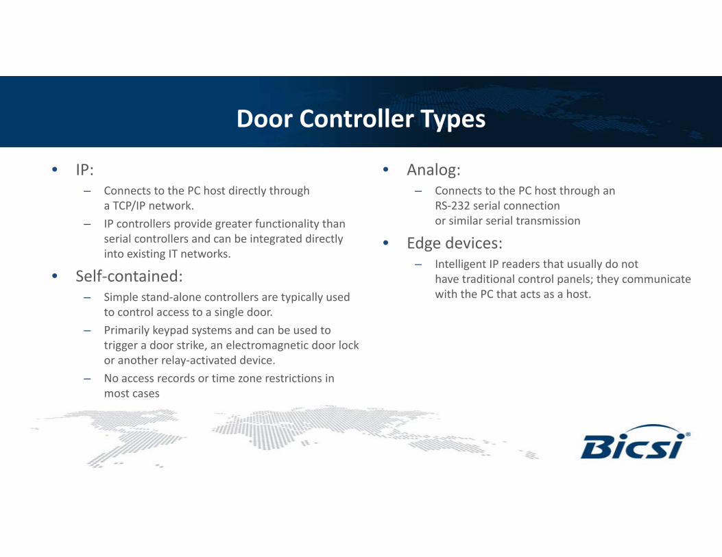
Door Controller Types
• IP: – Connects to the PC host directly through
a TCP/IP network. – IP controllers provide greater functionality than
serial controllers and can be integrated directly into existing IT networks.
• Self‐contained: – Simple stand‐alone controllers are typically used
to control access to a single door. – Primarily keypad systems and can be used to
trigger a door strike, an electromagnetic door lock or another relay‐activated device.
– No access records or time zone restrictions in most cases
• Analog: – Connects to the PC host through an
RS‐232 serial connection or similar serial transmission
• Edge devices: – Intelligent IP readers that usually do not
have traditional control panels; they communicate with the PC that acts as a host.
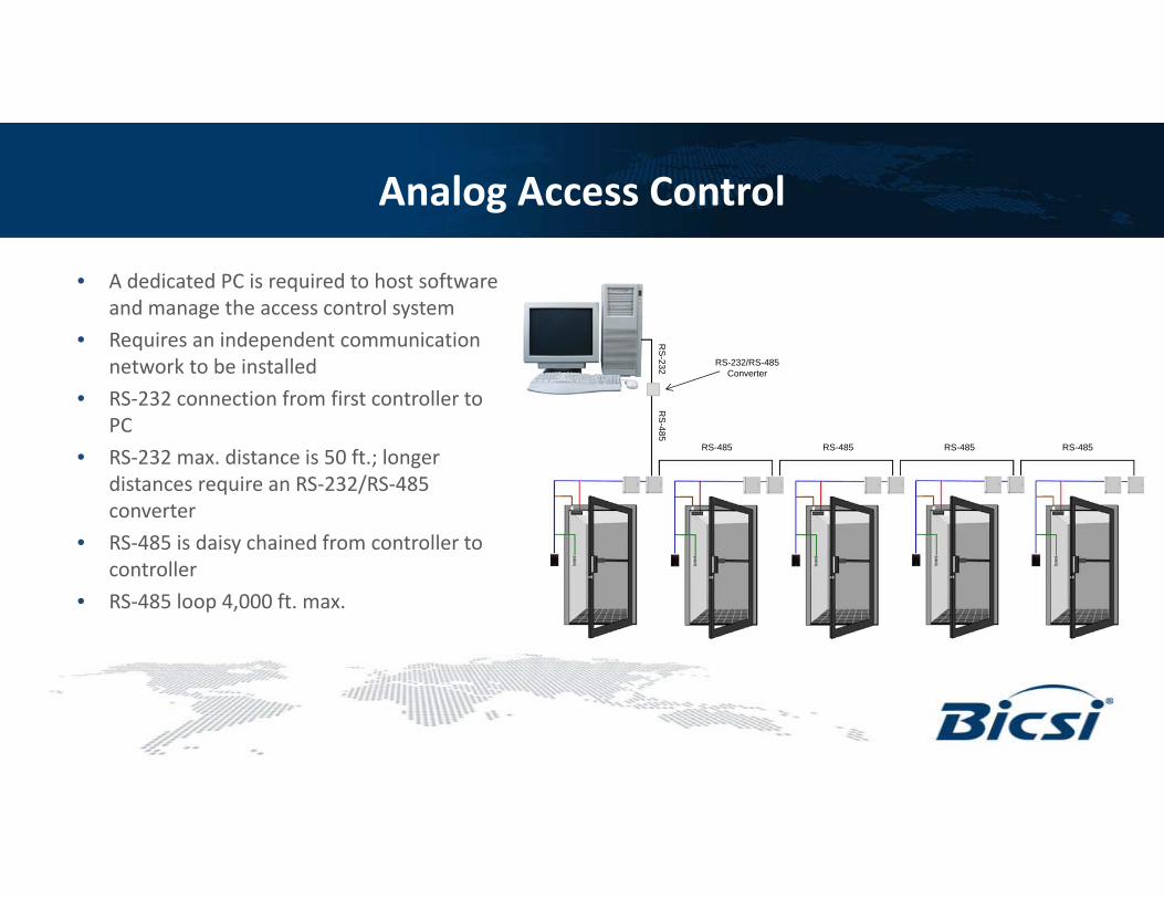
Analog Access Control
• A dedicated PC is required to host software and manage the access control system
• Requires an independent communication network to be installed
• RS‐232 connection from first controller to PC
• RS‐232 max. distance is 50 ft.; longer distances require an RS‐232/RS‐485 converter
• RS‐485 is daisy chained from controller to controller
• RS‐485 loop 4,000 ft. max.
RS
-232
RS-485
RS-232/RS-485 Converter
RS-485 RS-485 RS-485
RS
-485
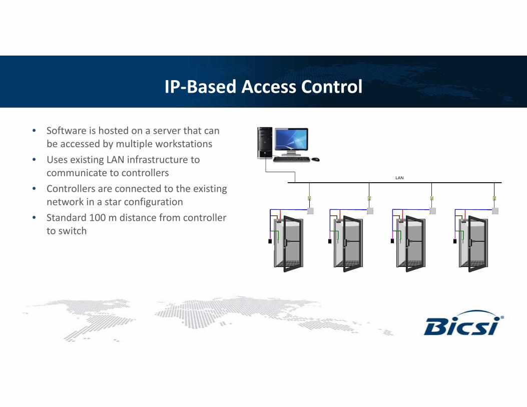
IP‐Based Access Control
• Software is hosted on a server that can be accessed by multiple workstations
• Uses existing LAN infrastructure to communicate to controllers
• Controllers are connected to the existing network in a star configuration
• Standard 100 m distance from controller to switch
LAN
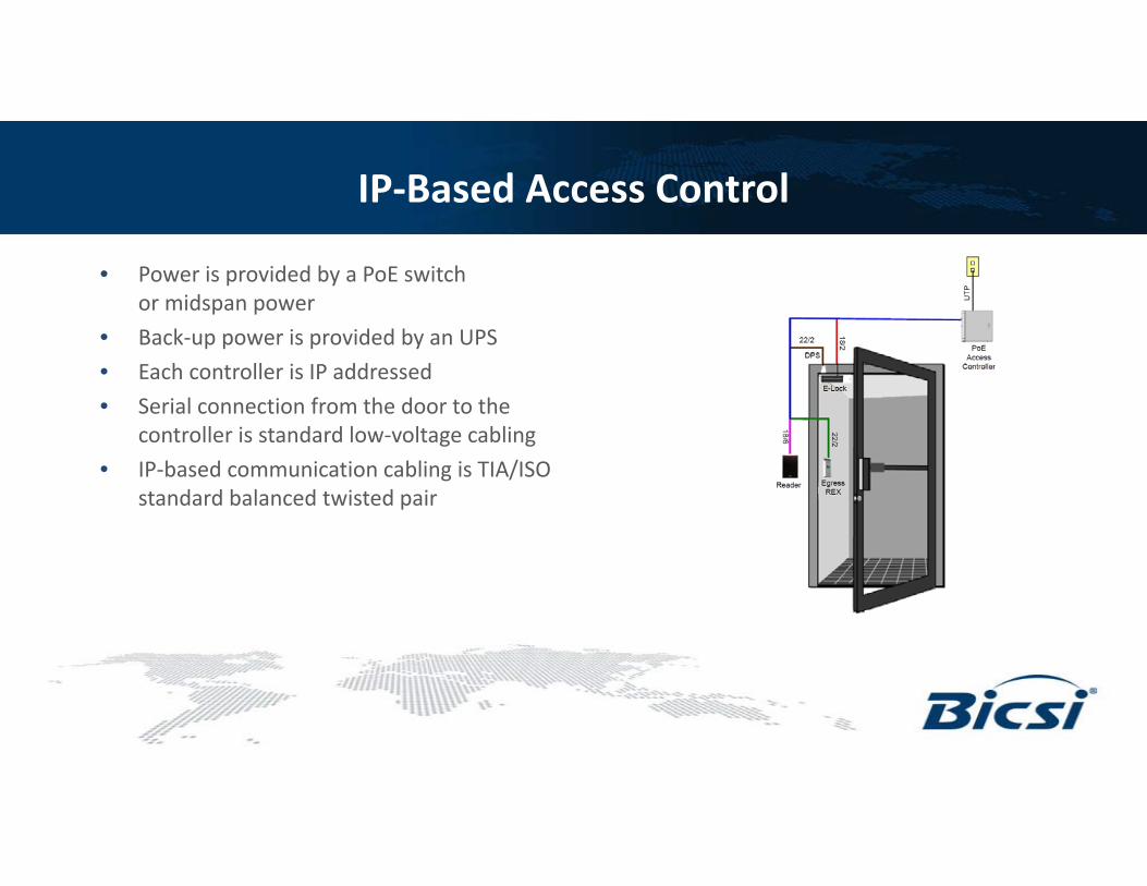
IP‐Based Access Control
• Power is provided by a PoE switch or midspan power
• Back‐up power is provided by an UPS• Each controller is IP addressed• Serial connection from the door to the
controller is standard low‐voltage cabling• IP‐based communication cabling is TIA/ISO
standard balanced twisted pair

DATA CENTER
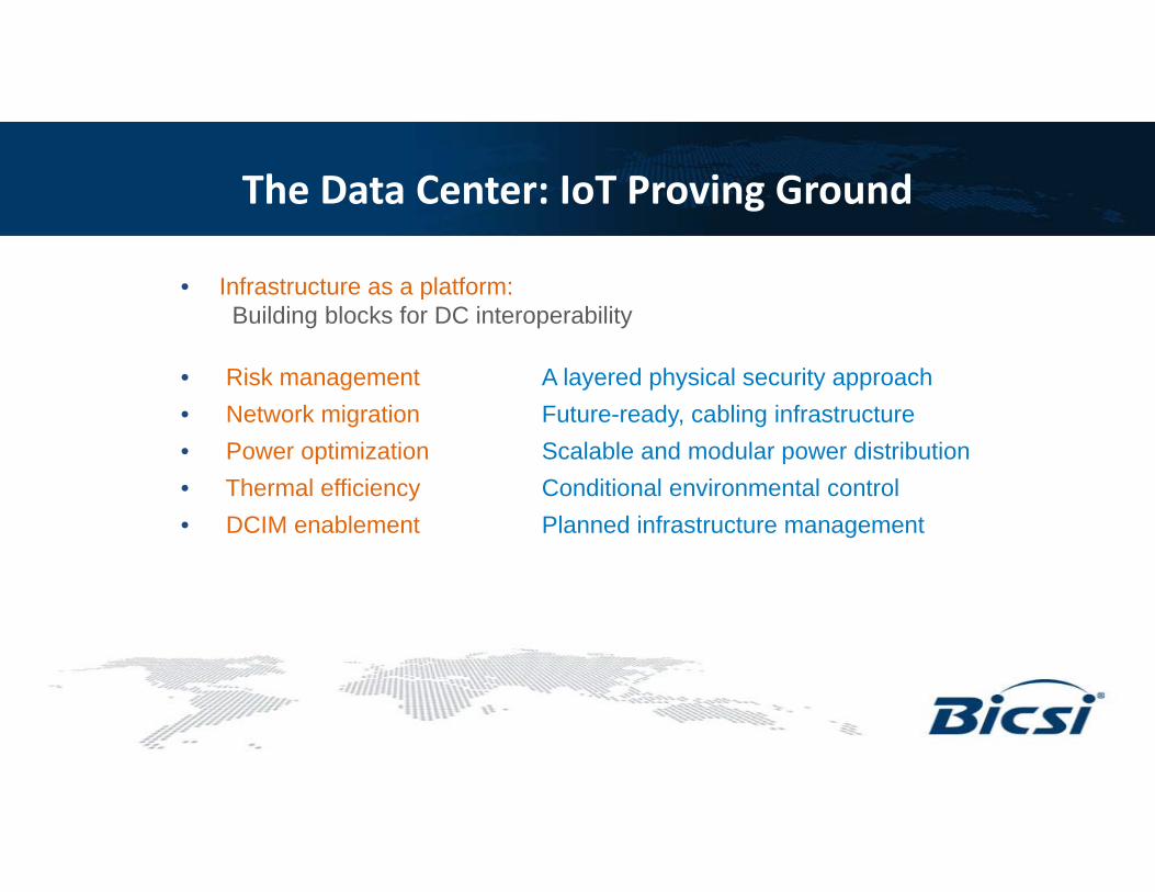
The Data Center: IoT Proving Ground
• Infrastructure as a platform:Building blocks for DC interoperability
• Risk management A layered physical security approach• Network migration Future-ready, cabling infrastructure• Power optimization Scalable and modular power distribution• Thermal efficiency Conditional environmental control• DCIM enablement Planned infrastructure management
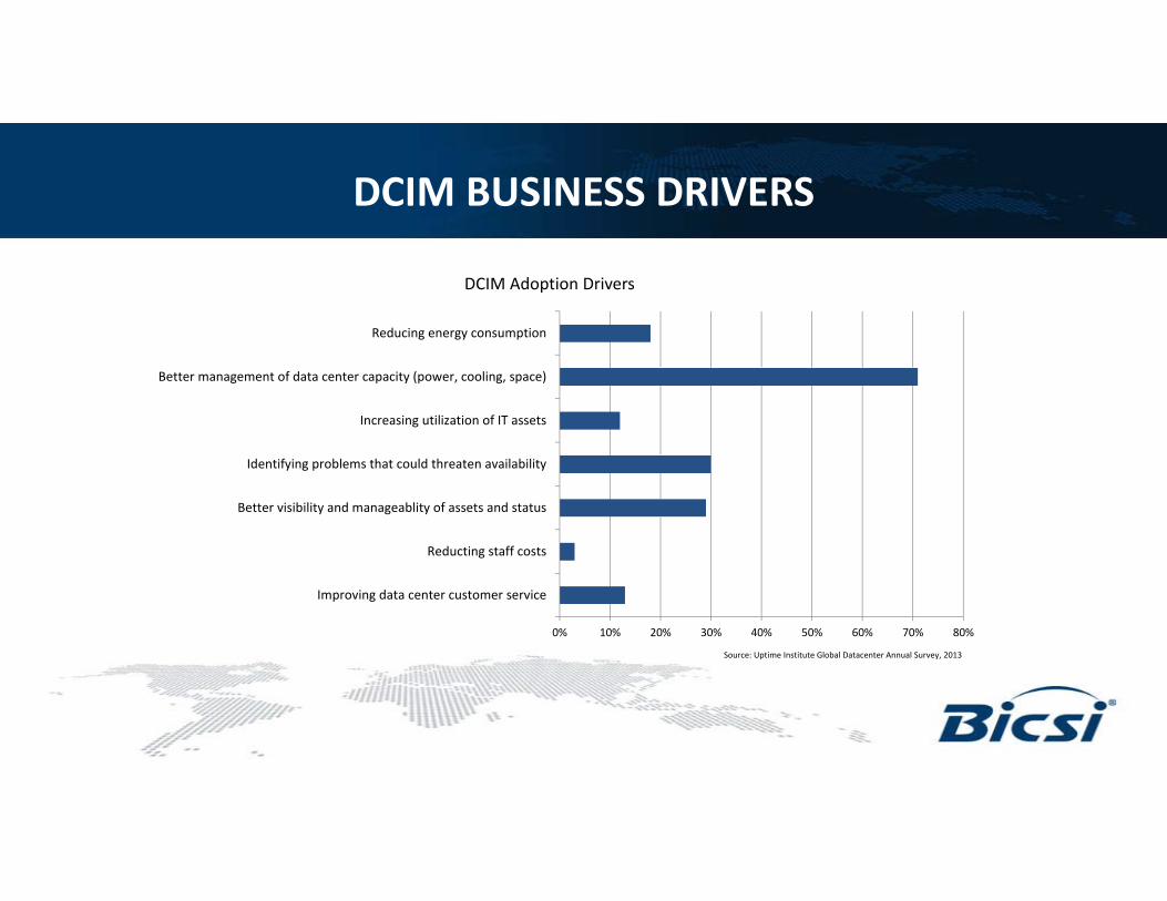
DCIM BUSINESS DRIVERS
0% 10% 20% 30% 40% 50% 60% 70% 80%
Improving data center customer service
Reducting staff costs
Better visibility and manageablity of assets and status
Identifying problems that could threaten availability
Increasing utilization of IT assets
Better management of data center capacity (power, cooling, space)
Reducing energy consumption
DCIM Adoption Drivers
Source: Uptime Institute Global Datacenter Annual Survey, 2013
AssetManagement
Environmental Monitoring
PowerMonitoring
ChangeManagement
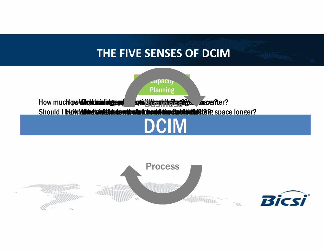
CapacityPlanning
Where is my equipment on the floor?What switch is my server connected to?How much maintenance do I have left on this device?
Do I have any hot or cold spots in my data center?What is the temperature of my cabinets?Can I raise the set point in my data center?
How much power am I consuming?How much power do I have available to me?How can I be more proactive to dealing with power issues?
How do I manage moves, adds and changes?How can I understand when work is completed?If I lose a power feed, what equipment does that effect upstream?
How much power, cooling, connectivity and space do I have?Should I build a new data center or can I stay in my existing space longer?Where is the most ideal place in the data center to put my new server?DCIM
Process
Business
THE FIVE SENSES OF DCIM
IoT in Action ‐ DC Case Study
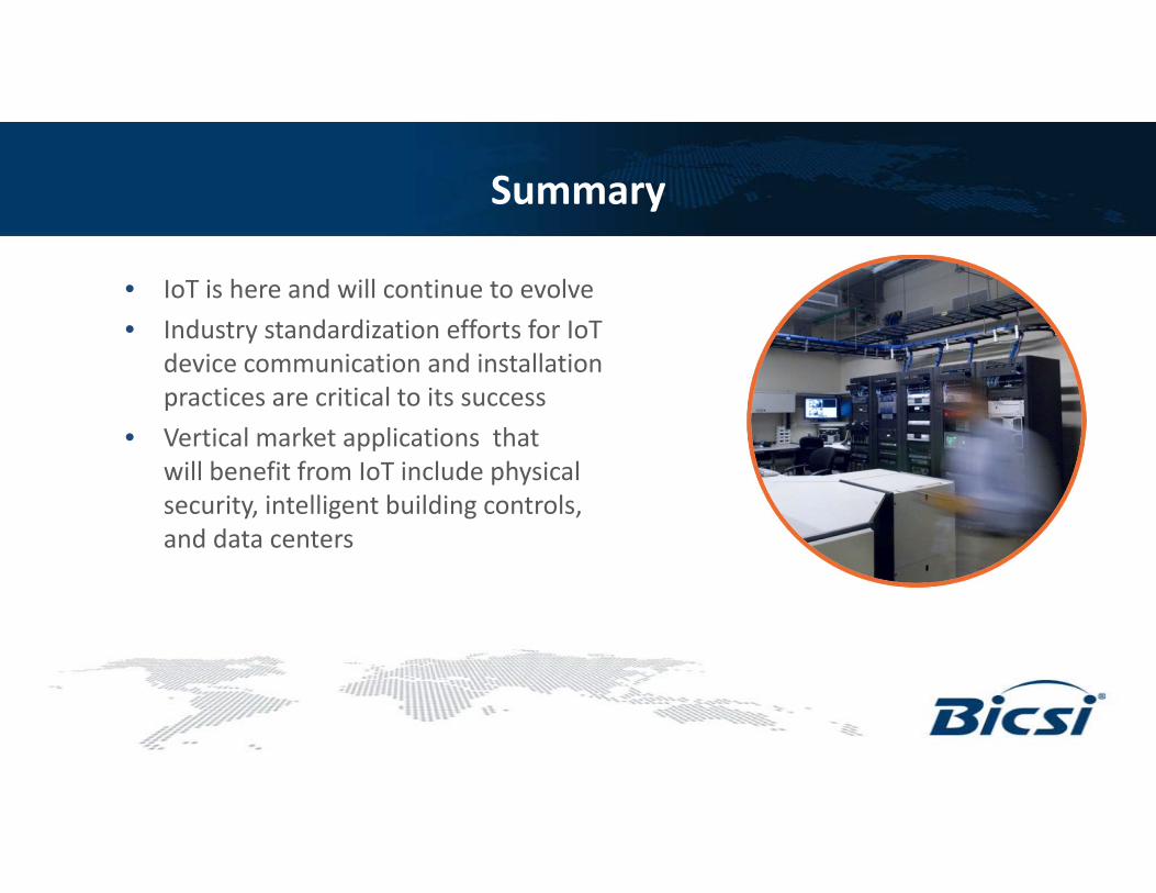
Summary
• IoT is here and will continue to evolve• Industry standardization efforts for IoT
device communication and installation practices are critical to its success
• Vertical market applications that will benefit from IoT include physical security, intelligent building controls, and data centers
Questions & Answers

THANK YOU.