Embed Size (px)
Citation preview
Demonstration of advanced reconnaissancetechniques with the airborne SAR/GMTIsensor PAMIR
A.R. Brenner and J.H.G. Ender
Abstract: PAMIR (Phased Array Multifunctional Imaging Radar) is an experimental airborneradar system that has been designed and built by the Research Institute for High FrequencyPhysics and Radar Techniques (FHR) of Forschungsgesellschaft fur AngewandteNaturwissenschaften (FGAN). The goal is to meet the growing demands for future reconnaissancesystems with respect to flexibility and multi-mode operation by the use of an electronically steer-able phased array antenna. The X-band system with a bandwidth of 1.8 GHz serves as a platformfor different tasks. One of the main objectives is to demonstrate synthetic aperture radar (SAR)imaging at a very high resolution and for a long range. The fine resolution will also be appliedfor inverse SAR (ISAR) imaging of ground moving targets. Moreover, five parallel receivingchannels allow array processing techniques like ground moving target indication (GMTI) viaspace–time adaptive processing, electronic counter-counter-measures and interferometric SARwith a very high 3D-resolution. A multi-channel scan-MTI mode with a range resolutionadapted to the target size allows for a wide area GMTI operation that can be complementedby target tracking. Together with the predecessor system AER-II, operating at a frequencyband contained in that of PAMIR, the possibility of experimental investigation of bistatic SARis given. SAR images of large urban areas and ISAR images of moving objects, both withfinest resolution down to the sub-decimetre scale, are presented. Results of GMTI in a widearea scanning mode and broadband bistatic experiments including true bistatic SAR processingare shown as well.
1 Introduction
Future requirements for air-to-ground surveillance andreconnaissance will involve challenging tasks for radarsensors. Ultra-high resolution and long range imaging capa-bilities, highly sensitive ground moving target indication(GMTI) acquired over a wide area and a multitude of soph-isticated operational modes are all requirements of the nextgeneration of SAR systems. The realisation of these tasksdemands the solution of many technological and methodicalproblems: ultra-high resolution down to the centimetre scalerequires the handling of transmission and reception of verylarge bandwidths. The aspired agility of the antenna canonly be realised with an electronically steerable phasedarray and subsequently by a finely quantised true timedelay (TTD) feed network. Modes for moving target indi-cation (MTI), single-pass interferometric imaging ormeasures against jamming and deception require multi-channel capabilities. The acquisition of the correspondingbroadband and multi-channel data generate extreme datarates and volumes. The broadband and wide angle scenariorequires a thorough modelling of the image formationprocess. Approximate processing is no longer applicable.
Systematic calibration, motion compensation and auto-focusing will become indispensable ingredients of radarprocessing.
With the aim to assess the achievable performance of suchradar systems, a new experimental platform will be realised:PAMIR, the Phased Array Multifunctional Imaging Radar.The most important design parameters are listed inTable 1. PAMIR, the follow-up system of AER-II [1], willserve as an airborne X-band platform for different tasks: itis intended to demonstrate SAR imaging at very highresolution and for long range (1 dm at 30 km; 1 ft at100 km). The fine resolution will also be achieved withinverse SAR (ISAR) imaging of ground moving targets. Aparticular research topic is the conception of a broadbandphased array with wide scan capabilities (+458).Moreover, five parallel receiving channels will allow arrayprocessing techniques like GMTI via space–time adaptiveprocessing (STAP), electronic counter-counter-measures(ECCM) and interferometric SAR (IfSAR) with very high3D-resolution. As the frequency band of AER-II is containedin one of the PAMIRs, it will also be possible to use bothsystems for bistatic SAR experiments.
2 Aspects of system design
In this article, the system design and specification will notbe given in detail, only the most important aspects ofradar modes, broadband waveform generation and signalacquisition, as well as the broadband active phased arrayantenna are described. More information can be found inEnder and Brenner [2].
# The Institution of Engineering and Technology 2006
IEE Proceedings online no. 20050044
doi:10.1049/ip-rsn:20050044
Paper first received 23rd May 2005 and in revised form 31st January 2006
The authors are with Forschungsgesellschaft fur Angewandte Naturwissen-schaften (FGAN) e.V., Research Institute for High Frequency Physics andRadar Techniques (FHR), Wachtberg-Werthhoven D-53343, Germany
E-mail: [email protected]
IEE Proc.-Radar Sonar Navig., Vol. 153, No. 2, April 2006152
2.1 Radar modes
Future radar tasks will be accomplished with sophisticatedmodes increasing dramatically the information content ofradar-based surveillance and reconnaissance techniquesstarting from finely resolved 2D images, over 3D interfero-metric images up to 3D images charged with informationabout the non-stationary fraction of the scene.
Two-dimensional mapping demands SAR modes that areadaptable to various scene sizes and featuring differentgeometric resolutions. Therefore, besides the canonicalstripmap and spotlight modes, there is a need for realisingthe so-called sliding spotlight mode [3]. By choosing thevelocity of the antenna’s footprint on the ground indepen-dent of the carrier’s velocity, it is possible to compromisebetween azimuthal resolution and image width.Furthermore, high beam agility of phased array antennasenables several spots to be imaged simultaneously. On-board SAR processing and image analysis provided, thesensor can be used in a multiscale acquisition mode, adapt-ing to concurrent needs in resolution and thus offeringadditional degrees of freedom in space–time resourceoptimisation and reducing the data considerably.
Imaging of the third spatial dimension can be achievedby interferometric SAR modes. In the case of reconfigurableantenna array, partitioning of the aperture into severalacross-track subapertures enables single-pass interfero-metry [4] and super resolution tomography [5, 6] promisingdetailed 3D analysis of man-made objects at fine groundresolution or acquisition of digital elevation maps andGIS (geographic information systems) data over complexurban areas. This potential can be increased significantlyby using the multi-baseline antenna in a multi-passinterferometric mode.
In addition to the stationary part of a scene, there is alsogreat interest in acquiring and indicating the non-stationaryfraction, that is, ground moving objects or so-called groundmoving targets. For the corresponding mode, the GMTImode, the aperture is partitioned into along-track subaper-tures. STAP [7–9] is applied suppressing the clutter
returns followed by a position estimator based on the sub-aperture signals. Ideally, the targets should be positionedinto a fine-resolved and simultaneously acquired SARimage. If large areas have to be kept under surveillance,for example, in traffic monitoring, the so-called scan-MTImode has to be applied, which can only be implementedby means of an electronically steerable antenna. If indi-cation and positioning of a moving target is not sufficientand, additionally, imaging of the target itself is desired,the ISAR mode has to be used. Supposing that the aspectangle variation between the sensor and the target is largeenough, for example, if the target follows a curved track,the antenna beam has to follow the target for an appropriatetime period and a highly resolved image of the targetbecomes feasible.
Finally, further information augmentation will arise byusing a spatially distributed antenna array, forming a coher-ently operating radar sensor network situated on airborne orspaceborne platforms. Here as well, electronically steerableand highly agile antennas are indispensible. Far from a com-prehensive realisation, the first steps towards this ambitiousgoal are the worldwide efforts concerning bistatic SARimaging [10–13].
2.2 Broadband radar operation
Three strategies with different advantages and disadvan-tages are designated to manage the total system bandwidthof about 1.8 GHz, namely, the concurrent subbands method,the de-ramping method and the synthetic bandwidthmethod.
In the concurrent subbands method, the transmit wave-form is generated over the entire bandwidth. Because ofthe bandwidth restrictions of the waveform generator, a fre-quency multiplication has to be used but to the detriment ofspectral purity. In the case of using several contiguouswaveform replicas with limited bandwidth and mixing bymeans of a fast switchable bank of local oscillators up toan intermediate band, this disadvantage can be avoided.By this means, chirps of 1.82 GHz bandwidth can be gener-ated using the stepped chirp principle, for example. In thecase of reception, five independent channels are tuned tofive subbands covering the entire bandwidth in parallel.This method is dedicated for a very high resolution modewith high pulse repetition frequency (PRF) demands.
Secondly, in the de-ramping method, the transmit pulsecovers the entire bandwidth, too. During the receiveperiod, a de-ramping waveform (i.e. a replica of the transmitwaveform that is slightly shifted in frequency) is generatedthat can be used by each individual channel. This method ispreferable in case of minor requirements with respect toswath extension (e.g. for ISAR). In addition, all channelsare now available for spatial processing (interferometricexploitation, multi-aperture clutter suppression or jammersuppression).
Thirdly, in the synthetic bandwidth method, the entirebandwidth is distributed over several pulses and the con-catenation of the subbands is done in a post-processingstep after signal acquisition. Because of the lower instan-taneous bandwidth this method offers advantages concern-ing broadband beamforming and beamsteering and can beused if the PRF demands are not too high.
2.3 Active phased array for broadbandmulti-channel applications
As described above, forthcoming ambitious radar modescan only be achieved by means of a sensor equipped with
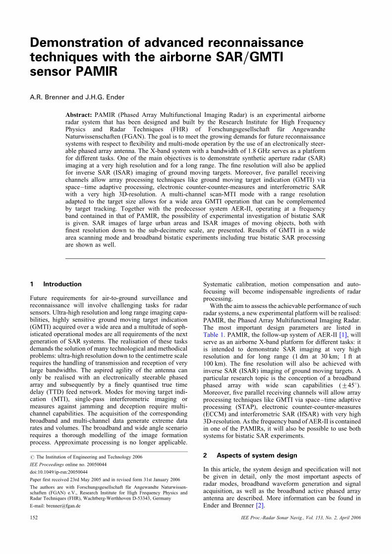
Table 1: Basic system parameters of PAMIR (final stageof extension)
Parameter Description
Carrier Transall C-160
Centre frequency 9.45 GHz
Bandwidth 1820 MHz
Resolution 0.1 � 0.1 m
Range 100 km
Channels 5 parallel receive channels
Main antenna Active phased array, electronically
steerable, 256 T/R modules
Transmit power 1280 W peak
Noise equivalent s0 at
maximum range
240 dB
Azimuth scan +458
Polarisation VV
Basic operational Squinted stripmap SAR
modes Spotlight and sliding mode SAR
Interferometric SAR
Scan-MTI
ISAR
IEE Proc.-Radar Sonar Navig., Vol. 153, No. 2, April 2006 153

a highly agile antenna. The only reasonable realisationwill be an electronically steerable active phased array thatis inherently designed for multi-channel broadbandapplications.
The main challenge in the realisation of a broadbandphased array is the need for the compensation of timedelays across the antenna aperture, for example, by use ofTTDs with different lengths forming a switchable delaynetwork. The topology and quantisation of this tree-structured network has to be optimised, whereas the corre-sponding cost function has to cover many aspects likebeam pattern degradations, insertion loss introduced bythe switches and ripple of the frequency response. Somesignal theoretical facets of this problem are discussed byBerens and Ender [14]. In case of the PAMIR antenna,which in its maximum elongation will have a length of4.25 m, the finest TTD quantisation has to be in the orderof 1 cm and the largest delay should be about 3 m.
The aperture of this antenna [15] is comprised up to 256Vivaldi columns that are subsumed into 16 autonomoussubarrays forming electrical and mechanical replaceableunits. This modular approach makes it possible to reconfi-gure the antenna in different ways: for example, a longlinear antenna (with superior GMTI properties) or a 2Darray (e.g. for multi-baseline IfSAR). The antenna frontendincludes further transmit/receive (T/R) modules, combin-ing networks, steering and control units and associatedpower supplies. Each subarray feeds 16 Vivaldi columns,each being composed of eight broadband Vivaldi radiatorscombined with a Wilkinson combiner to generate thedesired elevation pattern.
Fig. 1 shows a computer-aided design (CAD) model ofthe antenna and a CAD model of a subarray unit with thecalibration combiner attached behind the 16 Vivaldicolumns, which in addition can be turned mechanically inelevation. Coaxial wires with equal electrical lengthconnect the column outputs to the T/R modules, whichallow a broadband channel output power of 5 W. TheT/R modules exhibit two independent receive channelsper column. One receive channel leads directly to aWilkinson combiner, enabling beamforming solely withthe phase shifters (reasonable for narrowband applications).
The second channel is connected to a broadband switchableTTD network in microstrip technology allowing broadbandtime delay beamforming. The smallest line increment of theTTD network equals a third of a wavelength. The residualsof time delay beamforming are compensated for by the T/Rmodules’ phase shifters. The output of the TTD combinerstructure at subarray level directs to a switchable TTDmicrostrip network performing the combining of the 16subarrays. The associated steering, command and controlsignals are generated in a field-programmable gatearray at subarray level being fed by four distributedmicroprocessors in the front end.
3 Experimental results
Because of the scale and complexity of the necessary devel-opments, the realisation of our experimental system wasspread over several years and different stages of extension.This involved evaluation in one truck-based and two flightcampaigns: in 2002, the sensor was operated with onereceive channel and a mechanically steerable antennaarray (120 W peak) and was field-tested in various modessuch as stripmap-, sliding mode- and spotlight-SAR aswell as ISAR [2]. In 2003, the sensor was operated withthree receive channels and an electronically steerablephased array (200 W peak). In addition to further exper-iments concerning SAR and ISAR, emphasis was put onthe investigation of scan-MTI and bistatic experimentstogether with the sensor AER-II.
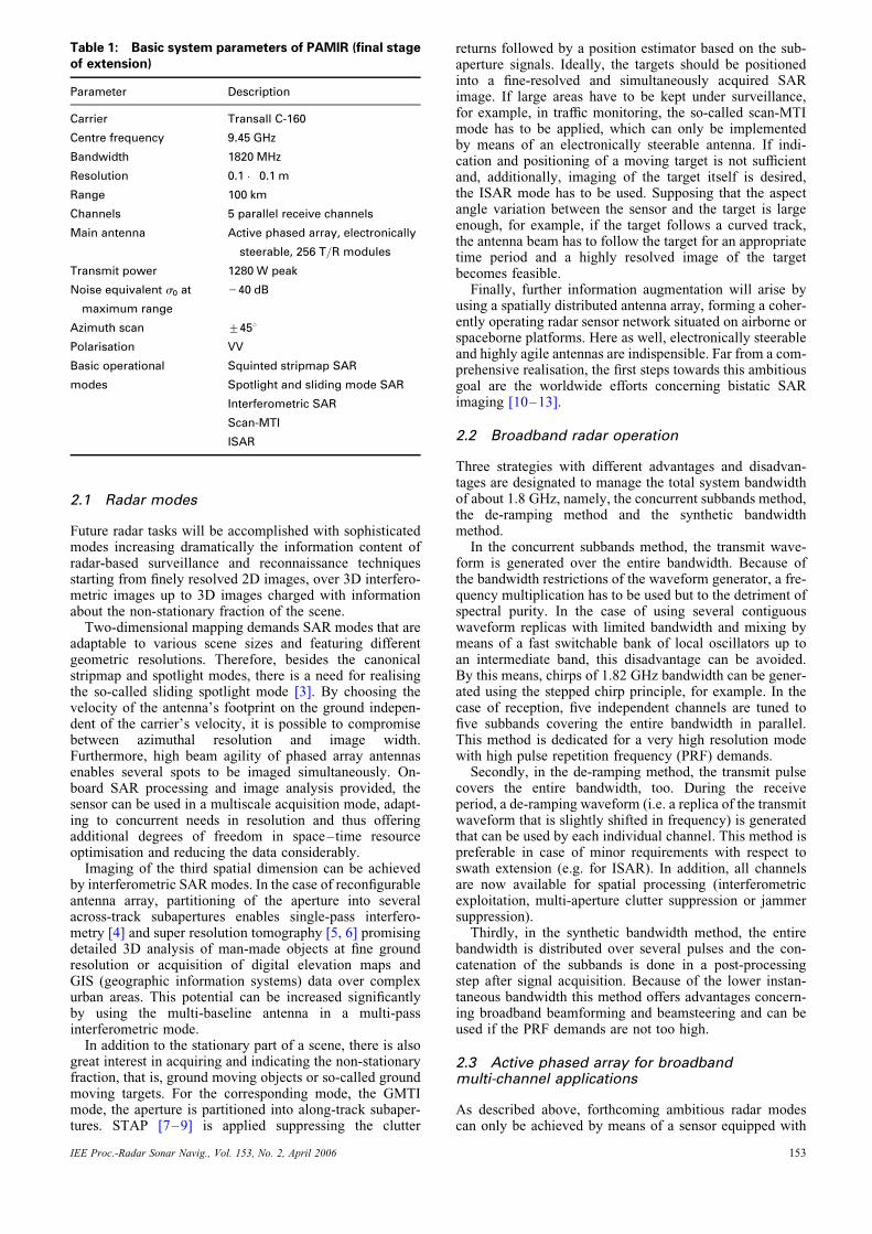
In Fig. 2, the current operational frontend and the exper-imental set-up of the system inside the carrier is shown. Theupgrade to five receive channels has now been completed.The antenna in its elongated configuration will bemounted under the wing of the carrier Transall C-160 (seeFig. 3). A modal analysis of the pod has been carried outand the flight approval was assigned.
3.1 SAR imaging
How fine the geometrical resolution of SAR images to beprovided, is an intensively discussed question. Surely, theanswer is dependent, for example on the image content
a b
Fig. 1 CAD models
a Antenna consisting of 16 autonomous subarrays with the internal grid and the cover with the radomeb Subarray unit with 16 Vivaldi columns and T/R modules, calibration network, beam steering network (true time delay) and digital control circuit
IEE Proc.-Radar Sonar Navig., Vol. 153, No. 2, April 2006154
and the interpreting instance. That is, for a screening oflarge areas by means of automatic image analysis, moderateresolution requirements are given, whereas for a detailedtechnical analysis performed by a human viewer, thefinest resolution is indispensible. Quantitative assistance isgiven on the one hand by the Civil NIIRS ReferenceGuide [16] itemising ten graduated levels with severalinterpretation tasks or criteria (e.g. detection, distinction,identification) forming each level. In addition, in the caseof electro-optical sensors, the NATO StandardisationAgreement No. 3769 [17] provides detailed informationabout minimum resolvable object sizes subject to the par-ticular interpretation task. From that, it is assumed that aresolution down to the centimetre scale should be at theimage analyst’s disposal. Providing evidence for the techno-logical and methodical feasibility of this demand is one ofthe principal objectives of our experimental system.
Beneath the technological challenges in realising a highresolution SAR sensor, the process of image formation isa task of particular importance. Only non-approximativeSAR processors must be used in this resolution scale.SAR processors formulated in the wavenumber domainbenefit from considerable savings in computational effort.
However, these processors suffer under real-world con-ditions of curved and non-equidistant-sampled syntheticapertures. An attractive alternative is the timedomain-based SAR processing technique. It is inherentlycapable of incorporating a non-ideal carrier track.However, the computational load of time domain proces-sing is very high. In an experimental context, timedomain processing can be preferred [2, 18, 19]. All SARimages presented in this contribution are processed by thismeans. It is worth mentioning that besides the compensationof non-ideal aircraft trajectory, a careful calibration is aprerequisite for finely resolved high-quality images.Residuals in trajectory estimation have to be taken intoaccount by means of autofocusing techniques.
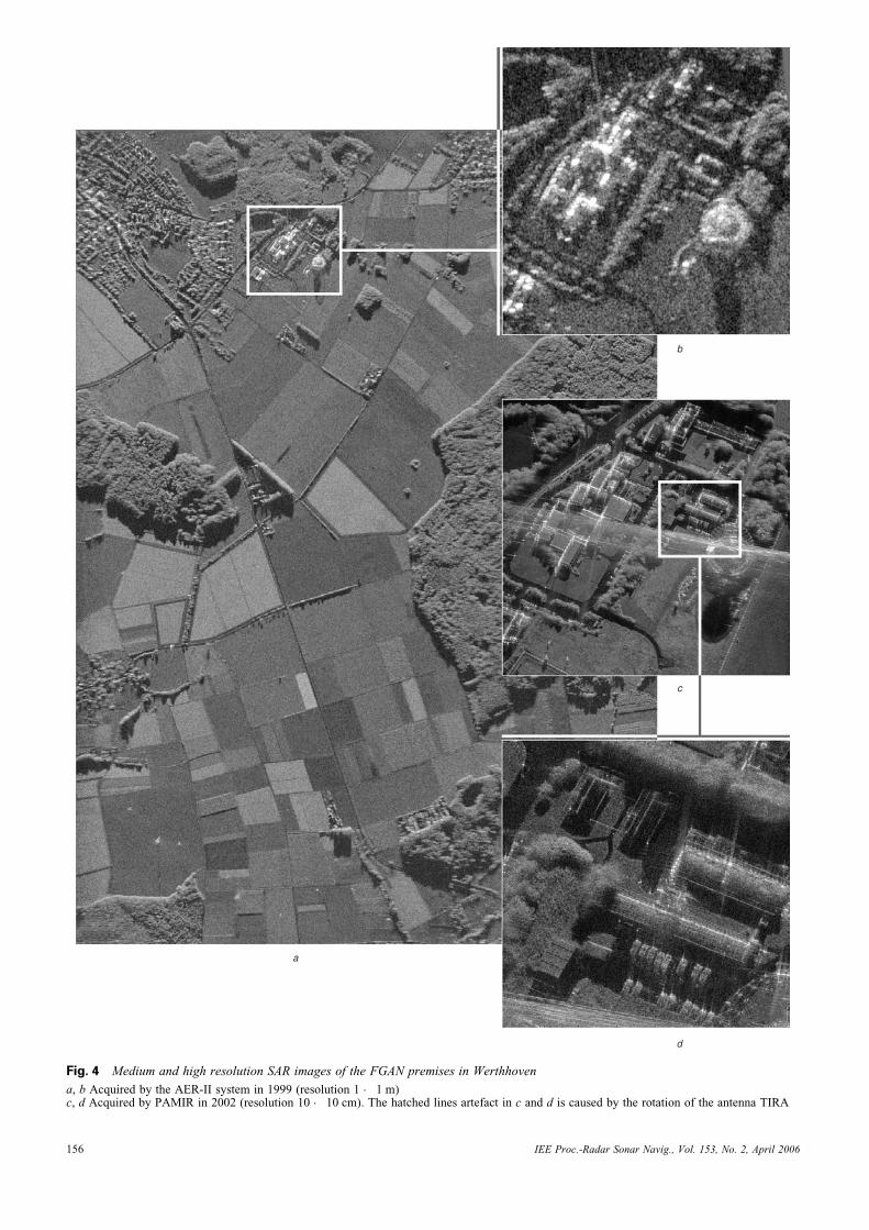
To illustrate the capability of finely resolved SARimages, a view of the same scene with different resolutionsis displayed. In Fig. 4, medium and high resolution SARimages of the FGAN premises in Werthhoven acquired bythe AER-II system and the new system are shown.Whereas in Fig. 4a, the image quality of a scene coveringsome 10 km2 appears to be very good, zooming into a sub-scene (Fig. 4b) reveals difficulties in the identification ofmany objects and image structures. The interpretation and
a b
Fig. 2 Experimental set-up
a Current frontend consisting of an electronically steerable array with 40 sector horn elementsb Experimental set-up of PAMIR inside the carrier Transall C-160
a b
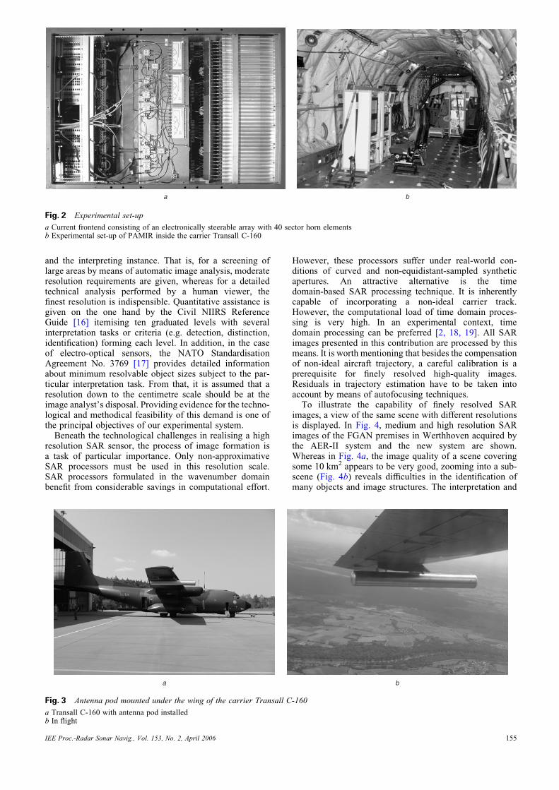
Fig. 3 Antenna pod mounted under the wing of the carrier Transall C-160
a Transall C-160 with antenna pod installedb In flight
IEE Proc.-Radar Sonar Navig., Vol. 153, No. 2, April 2006 155
a
b
c
d
Fig. 4 Medium and high resolution SAR images of the FGAN premises in Werthhoven
a, b Acquired by the AER-II system in 1999 (resolution 1 � 1 m)c, d Acquired by PAMIR in 2002 (resolution 10 � 10 cm). The hatched lines artefact in c and d is caused by the rotation of the antenna TIRA
IEE Proc.-Radar Sonar Navig., Vol. 153, No. 2, April 2006156
contextual understanding of the SAR image is really thedomain of experienced image interpreters. With a high-resolution capability, the situation changes dramatically:in Fig. 4c the image context is made accessible to eventhe untrained viewer and helps the trained one in the caseof tight temporal constraints. In the zoomed subscene inFig. 4d, vehicles, small trees and bushes can be clearlyidentified. In comparison with SAR imaging in the metreresolution scale, a wealth of details now arise.
The images prove the sensor’s capabilities with respect tospatial resolution, range and image dynamic. For near-rangeacquisition (up to 10 km), a geometrical resolution at thesub-decimetre level (down to 5 � 8 cm) could be demon-strated [20, 21].
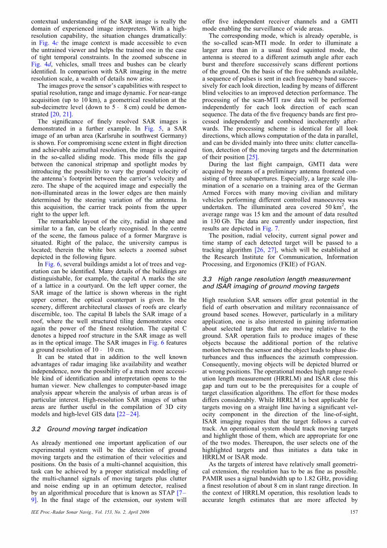
The significance of finely resolved SAR images isdemonstrated in a further example. In Fig. 5, a SARimage of an urban area (Karlsruhe in southwest Germany)is shown. For compromising scene extent in flight directionand achievable azimuthal resolution, the image is acquiredin the so-called sliding mode. This mode fills the gapbetween the canonical stripmap and spotlight modes byintroducing the possibility to vary the ground velocity ofthe antenna’s footprint between the carrier’s velocity andzero. The shape of the acquired image and especially thenon-illuminated areas in the lower edges are then mainlydetermined by the steering variation of the antenna. Inthis acquisition, the carrier track points from the upperright to the upper left.
The remarkable layout of the city, radial in shape andsimilar to a fan, can be clearly recognised. In the centreof the scene, the famous palace of a former Margrave issituated. Right of the palace, the university campus islocated; therein the white box selects a zoomed subsetdepicted in the following figure.
In Fig. 6, several buildings amidst a lot of trees and veg-etation can be identified. Many details of the buildings aredistinguishable, for example, the capital A marks the siteof a lattice in a courtyard. On the left upper corner, theSAR image of the lattice is shown whereas in the rightupper corner, the optical counterpart is given. In thescenery, different architectural classes of roofs are clearlydiscernible, too. The capital B labels the SAR image of aroof, where the well structured tiling demonstrates onceagain the power of the finest resolution. The capital Cdenotes a hipped roof structure in the SAR image as wellas in the optical image. The SAR images in Fig. 6 featuresa ground resolution of 10 � 10 cm.
It can be stated that in addition to the well knownadvantages of radar imaging like availability and weatherindependence, now the possibility of a much more accessi-ble kind of identification and interpretation opens to thehuman viewer. New challenges to computer-based imageanalysis appear wherein the analysis of urban areas is ofparticular interest. High-resolution SAR images of urbanareas are further useful in the compilation of 3D citymodels and high-level GIS data [22–24].
3.2 Ground moving target indication
As already mentioned one important application of ourexperimental system will be the detection of groundmoving targets and the estimation of their velocities andpositions. On the basis of a multi-channel acquisition, thistask can be achieved by a proper statistical modelling ofthe multi-channel signals of moving targets plus clutterand noise ending up in an optimum detector, realisedby an algorithmical procedure that is known as STAP [7–9]. In the final stage of the extension, our system will
offer five independent receiver channels and a GMTImode enabling the surveillance of wide areas.
The corresponding mode, which is already operable, isthe so-called scan-MTI mode. In order to illuminate alarger area than in a usual fixed squinted mode, theantenna is steered to a different azimuth angle after eachburst and therefore successively scans different portionsof the ground. On the basis of the five subbands available,a sequence of pulses is sent in each frequency band succes-sively for each look direction, leading by means of differentblind velocities to an improved detection performance. Theprocessing of the scan-MTI raw data will be performedindependently for each look direction of each scansequence. The data of the five frequency bands are first pro-cessed independently and combined incoherently after-wards. The processing scheme is identical for all lookdirections, which allows computation of the data in parallel,and can be divided mainly into three units: clutter cancella-tion, detection of the moving targets and the determinationof their position [25].
During the last flight campaign, GMTI data wereacquired by means of a preliminary antenna frontend con-sisting of three subapertures. Especially, a large scale illu-mination of a scenario on a training area of the GermanArmed Forces with many moving civilian and militaryvehicles performing different controlled manoeuvres wasundertaken. The illuminated area covered 50 km2, theaverage range was 15 km and the amount of data resultedin 130 Gb. The data are currently under inspection, firstresults are depicted in Fig. 7.
The position, radial velocity, current signal power andtime stamp of each detected target will be passed to atracking algorithm [26, 27], which will be established atthe Research Institute for Communication, InformationProcessing, and Ergonomics (FKIE) of FGAN.
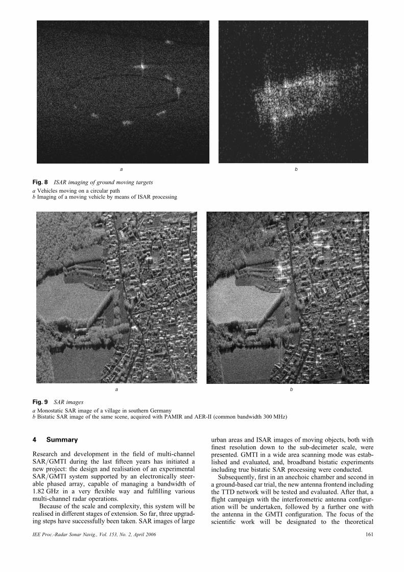
3.3 High range resolution length measurementand ISAR imaging of ground moving targets
High resolution SAR sensors offer great potential in thefield of earth observation and military reconnaissance ofground based scenes. However, particularly in a militaryapplication, one is also interested in gaining informationabout selected targets that are moving relative to theground. SAR operation fails to produce images of theseobjects because the additional portion of the relativemotion between the sensor and the object leads to phase dis-turbances and thus influences the azimuth compression.Consequently, moving objects will be depicted blurred orat wrong positions. The operational modes high range resol-ution length measurement (HRRLM) and ISAR close thisgap and turn out to be the prerequisites for a couple oftarget classification algorithms. The effort for these modesdiffers considerably. While HRRLM is best applicable fortargets moving on a straight line having a significant vel-ocity component in the direction of the line-of-sight,ISAR imaging requires that the target follows a curvedtrack. An operational system should track moving targetsand highlight those of them, which are appropriate for oneof the two modes. Thereupon, the user selects one of thehighlighted targets and thus initiates a data take inHRRLM or ISAR mode.
As the targets of interest have relatively small geometri-cal extension, the resolution has to be as fine as possible.PAMIR uses a signal bandwidth up to 1.82 GHz, providinga finest resolution of about 8 cm in slant range direction. Inthe context of HRRLM operation, this resolution leads toaccurate length estimates that are more affected by
IEE Proc.-Radar Sonar Navig., Vol. 153, No. 2, April 2006 157
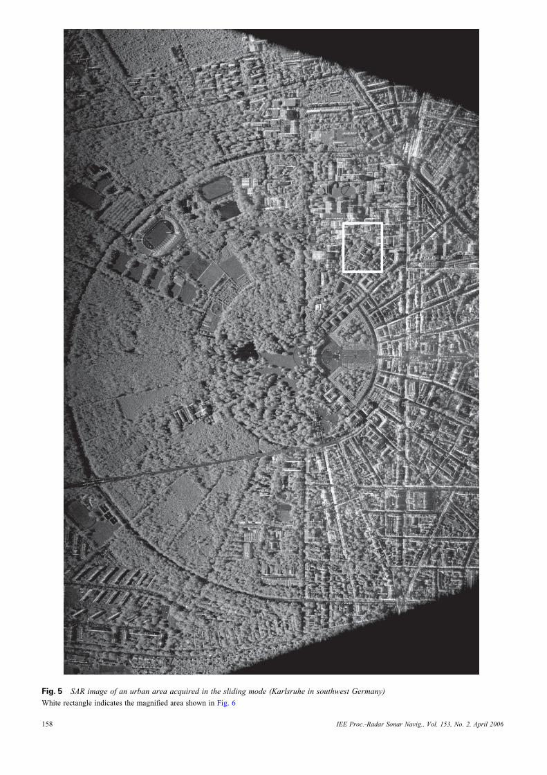
Fig. 5 SAR image of an urban area acquired in the sliding mode (Karlsruhe in southwest Germany)
White rectangle indicates the magnified area shown in Fig. 6
IEE Proc.-Radar Sonar Navig., Vol. 153, No. 2, April 2006158
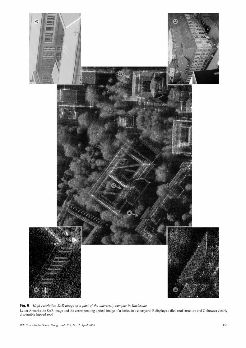
Fig. 6 High resolution SAR image of a part of the university campus in Karlsruhe
Letter A marks the SAR image and the corresponding optical image of a lattice in a courtyard. B displays a tiled roof structure and C shows a clearlydiscernible hipped roof
IEE Proc.-Radar Sonar Navig., Vol. 153, No. 2, April 2006 159
shadowing effects and track motion uncertainties than bythe limited range resolution.
ISAR imaging of ground moving targets is a challengingtask, as moving target echoes have to compete with theclutter background. Moreover, as the target motion isunknown, autofocusing methods have to be applied exten-sively. The ISAR processing is still in development.Nevertheless, some main building blocks have beenimplemented. On the basis of the tracking information ofa real time tracker, a first motion compensation can beaccomplished. A range compression and short timeazimuth Fourier transform convert the echoes into range-Doppler domain. A kind of focusing happened in this datarepresentation and the sequence of the short time segmentsform a ‘movie’. On the basis of this movie, a parametricmotion model will be evaluated, which enables a reproces-sing comprising a refined motion compensation.
During the last flight campaigns, cooperating targetsdrove in circles of different diameters. One snapshot ofthe movie in the range-Doppler domain is depicted inFig. 8 on the left-hand side. This figure also presents anISAR result of one moving truck on the right. FurtherISAR results can be found in Ender and Brenner [2].
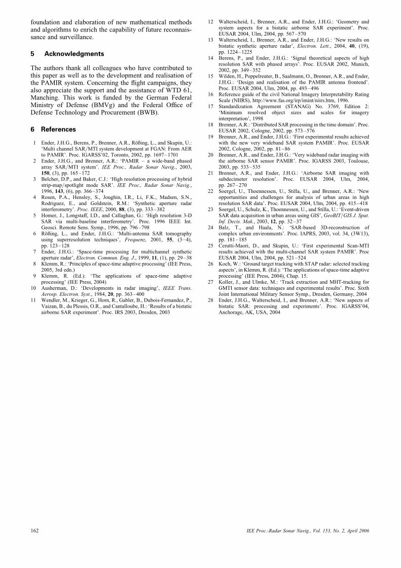
3.4 Bistatic SAR imaging
In bistatic SAR imaging, transmitter and receiver arelocated on different platforms. Besides the increasing com-plexity in the realisation of this configuration, several
advantages arise. First, in military applications, the vulner-ability is reduced, because the transmitter can bepositioned far away, while the passive receiver can intrudesilently and is difficult to detect. In addition, the differentbehaviour with respect to bistatic radar cross sectionimproves, for example the detection of stealthy targets.Moreover, if the transmitter platform is equipped with anadditional receiving antenna, the emerging different aspectangles enhance imaging and moving target detection.Though there were early activities on this topic [10],concern has been increasing rapidly in the past years [11–13].
An airborne bistatic flight campaign was undertaken in2003. The two X-band sensors AER-II and PAMIR wereused in several flight configurations with bistatic anglesranging from 13 up to 768 and a common bandwidth of300 MHz. The aircraft flew in the so-called ‘translationalinvariant configuration’, that is, the transmitter and thereceiver possess the same velocity vector, so no beamsteer-ing was necessary. First SAR images demonstrate thesuccess of the campaign. In Fig. 9 on the left side, a mono-static acquired SAR scene is depicted. In comparison, thesame scene acquired in bistatic configuration is shown onthe right-hand side. Because of an extended receivewindow, an explicit synchronisation on system level wasnot needed. The image formation itself was carried out bymeans of a generalised backprojection processor. The pro-cessing of bistatic data remains a matter of research. Inparticular, range migration processor types for bistaticapplications would be in great demand [28].
Fig. 7 Detected and positioned ground moving targets acquired with the scan-MTI mode
IEE Proc.-Radar Sonar Navig., Vol. 153, No. 2, April 2006160
4 Summary
Research and development in the field of multi-channelSAR/GMTI during the last fifteen years has initiated anew project: the design and realisation of an experimentalSAR/GMTI system supported by an electronically steer-able phased array, capable of managing a bandwidth of1.82 GHz in a very flexible way and fulfilling variousmulti-channel radar operations.
Because of the scale and complexity, this system will berealised in different stages of extension. So far, three upgrad-ing steps have successfully been taken. SAR images of large
urban areas and ISAR images of moving objects, both withfinest resolution down to the sub-decimeter scale, werepresented. GMTI in a wide area scanning mode was estab-lished and evaluated, and, broadband bistatic experimentsincluding true bistatic SAR processing were conducted.
Subsequently, first in an anechoic chamber and second ina ground-based car trial, the new antenna frontend includingthe TTD network will be tested and evaluated. After that, aflight campaign with the interferometric antenna configur-ation will be undertaken, followed by a further one withthe antenna in the GMTI configuration. The focus of thescientific work will be designated to the theoretical
a b
Fig. 8 ISAR imaging of ground moving targets
a Vehicles moving on a circular pathb Imaging of a moving vehicle by means of ISAR processing
a b
Fig. 9 SAR images
a Monostatic SAR image of a village in southern Germanyb Bistatic SAR image of the same scene, acquired with PAMIR and AER-II (common bandwidth 300 MHz)
IEE Proc.-Radar Sonar Navig., Vol. 153, No. 2, April 2006 161
foundation and elaboration of new mathematical methodsand algorithms to enrich the capability of future reconnais-sance and surveillance.
5 Acknowledgments
The authors thank all colleagues who have contributed tothis paper as well as to the development and realisation ofthe PAMIR system. Concerning the flight campaigns, theyalso appreciate the support and the assistance of WTD 61,Manching. This work is funded by the German FederalMinistry of Defense (BMVg) and the Federal Office ofDefense Technology and Procurement (BWB).
6 References
1 Ender, J.H.G., Berens, P., Brenner, A.R., Roßing, L., and Skupin, U.:‘Multi channel SAR/MTI system development at FGAN: From AERto PAMIR’. Proc. IGARSS’02, Toronto, 2002, pp. 1697–1701
2 Ender, J.H.G., and Brenner, A.R.: ‘PAMIR – a wide-band phasedarray SAR/MTI system’. IEE Proc., Radar Sonar Navig., 2003,150, (3), pp. 165–172
3 Belcher, D.P., and Baker, C.J.: ‘High resolution processing of hybridstrip-map/spotlight mode SAR’. IEE Proc., Radar Sonar Navig.,1996, 143, (6), pp. 366–374
4 Rosen, P.A., Hensley, S., Joughin, I.R., Li, F.K., Madsen, S.N.,Rodriguez, E., and Goldstein, R.M.: ‘Synthetic aperture radarinterferometry’. Proc. IEEE, 2000, 88, (3), pp. 333–382
5 Homer, J., Longstaff, I.D., and Callaghan, G.: ‘High resolution 3-DSAR via multi-baseline interferometry’. Proc. 1996 IEEE Int.Geosci. Remote Sens. Symp., 1996, pp. 796–798
6 Roßing, L., and Ender, J.H.G.: ‘Multi-antenna SAR tomographyusing superresolution techniques’, Frequenz, 2001, 55, (3–4),pp. 123–128
7 Ender, J.H.G.: ‘Space-time processing for multichannel syntheticaperture radar’, Electron. Commun. Eng. J., 1999, 11, (1), pp. 29–38
8 Klemm, R.: ‘Principles of space-time adaptive processing’ (IEE Press,2005, 3rd edn.)
9 Klemm, R. (Ed.): ‘The applications of space-time adaptiveprocessing’ (IEE Press, 2004)
10 Ausherman, D.: ‘Developments in radar imaging’, IEEE Trans.Aerosp. Electron. Syst., 1984, 20, pp. 363–400
11 Wendler, M., Krieger, G., Horn, R., Gabler, B., Dubois-Fernandez, P.,Vaizan, B., du Plessis, O.R., and Cantalloube, H.: ‘Results of a bistaticairborne SAR experiment’. Proc. IRS 2003, Dresden, 2003
12 Walterscheid, I., Brenner, A.R., and Ender, J.H.G.: ‘Geometry andsystem aspects for a bistatic airborne SAR experiment’. Proc.EUSAR 2004, Ulm, 2004, pp. 567–570
13 Walterscheid, I., Brenner, A.R., and Ender, J.H.G.: ‘New results onbistatic synthetic aperture radar’, Electron. Lett., 2004, 40, (19),pp. 1224–1225
14 Berens, P., and Ender, J.H.G.: ‘Signal theoretical aspects of highresolution SAR with phased arrays’. Proc. EUSAR 2002, Munich,2002, pp. 349–352
15 Wilden, H., Poppelreuter, B., Saalmann, O., Brenner, A.R., and Ender,J.H.G.: ‘Design and realisation of the PAMIR antenna frontend’.Proc. EUSAR 2004, Ulm, 2004, pp. 493–496
16 Reference guide of the civil National Imagery Interpretability RatingScale (NIIRS), http://www.fas.org/irp/imint/niirs.htm, 1996.
17 Standardization Agreement (STANAG) No. 3769, Edition 2:‘Minimum resolved object sizes and scales for imageryinterpretation’, 1998
18 Brenner, A.R.: ‘Distributed SAR processing in the time domain’. Proc.EUSAR 2002, Cologne, 2002, pp. 573–576
19 Brenner, A.R., and Ender, J.H.G.: ‘First experimental results achievedwith the new very wideband SAR system PAMIR’. Proc. EUSAR2002, Cologne, 2002, pp. 81–86
20 Brenner, A.R., and Ender, J.H.G.: ‘Very wideband radar imaging withthe airborne SAR sensor PAMIR’. Proc. IGARSS 2003, Toulouse,2003, pp. 533–535
21 Brenner, A.R., and Ender, J.H.G.: ‘Airborne SAR imaging withsubdecimeter resolution’. Proc. EUSAR 2004, Ulm, 2004,pp. 267–270
22 Soergel, U., Thoennessen, U., Stilla, U., and Brenner, A.R.: ‘Newopportunities and challenges for analysis of urban areas in highresolution SAR data’. Proc. EUSAR 2004, Ulm, 2004, pp. 415–418
23 Soergel, U., Schulz, K., Thoennessen, U., and Stilla, U.: ‘Event-drivenSAR data acquisition in urban areas using GIS’, GeoBIT/GIS J. Spat.Inf. Decis. Mak., 2003, 12, pp. 32–37
24 Balz, T., and Haala, N.: ‘SAR-based 3D-reconstruction ofcomplex urban environments’. Proc. IAPRS, 2003, vol. 34, (3W13),pp. 181–185
25 Cerutti-Maori, D., and Skupin, U.: ‘First experimental Scan-MTIresults achieved with the multi-channel SAR system PAMIR’. ProcEUSAR 2004, Ulm, 2004, pp. 521–524
26 Koch, W.: ‘Ground target tracking with STAP radar: selected trackingaspects’, in Klemm, R. (Ed.): ‘The applications of space-time adaptiveprocessing’ (IEE Press, 2004), Chap. 15.
27 Koller, J., and Ulmke, M.: ‘Track extraction and MHT-tracking forGMTI sensor data: techniques and experimental results’. Proc. SixthJoint International Military Sensor Symp., Dresden, Germany, 2004
28 Ender, J.H.G., Walterscheid, I., and Brenner, A.R.: ‘New aspects ofbistatic SAR: processing and experiments’. Proc. IGARSS’04,Anchorage, AK, USA, 2004
IEE Proc.-Radar Sonar Navig., Vol. 153, No. 2, April 2006162