Embed Size (px)
Citation preview
Department of Mechanical Engineering
DRIVING MODULE
Marcus Abrahamsson
Xavier Evrat Christian Magnusson
Henrik Svensson
Institutionen för maskinteknik
Blekinge Tekniska Högskola
Karlskrona
2002
Följande arbete är utfört som en obligatorisk del av utbildningen på programmet Utvecklingsteknik vid Institutionen för Maskinteknik på Blekinge Tekniska Högskola. Following project is done as an obligatory part of the education on the program Developing technology. “Utvecklingsteknik” at the institution for mechanical engineering at the Blekinge Tekniska Högskola.
Department of Mechanical Engineering
1 Preface This project is an examination these for pass the Bachelor of Science in Mechanical Engineering with Emphasis on Product Development at the BLEKINGE INSTITUTE OF TECHNOLOGY. This work was carried out under the supervision of Dr. Mats Walter and Dr. Morgan Klang.
This research project was performed in co-operation between the University and “Elautomation Syd AB” the society which needed to manufacture for SAS a driving module for their Cart.
The project group consists of three students from the BLEKINGE INSTITUTE OF TECHNOLOGY and one from an Engineering school “EIGSI La Rochelle” from France. He was involved in this project as an exchange student for two months and a half until the middle of April.
We wish to express our sincere appreciation to Christer Georgsson, the inventor, Knut Blom and Jonas Persson from “Elautomation Syd AB” and Peter Melander from SAS for their help and engagement throughout the work. Finally we want to thank Dr. Mats Walter and Dr. Morgan Klang for their valuable support and advice.
Karlskrona the 5th of May 2002
Marcus Abrahamsson Christian Magnusson Henrik Svensson
Xavier Evrat
(Exchange student)
2
Department of Mechanical Engineering
2 Summary This project has been made in co-operation with “Elautomation Syd AB” located in Svängsta. This study is partly based on a report from Högskolan I LULEÅ University written by Jörgen Winkel, Berit Ekblom and Bengt Tillberg called “Fysiska Belastningar på Kabinpersonal vid trafikflygning”. We needed to design an electric-driven module to place underneath a serving-cart, to facilitate the work made by the cabin personal and thereby prevent work injuries.
This degree project is divided in three parts: ”Principkonstruktion”, ”Primärkonstruktion” and “prototype manufacturing”, according to the Fredy Olsson method.
In the first part of the project Principkonstruktion” we analysed the criterions and the wishes from our customer in order to determine the principals. We also investigated the standardization rules use in the airplane construction. After combining the proposals we checked the fulfilling of this criterions.
Secondly on the ”Primärkonstruktion” phase, few test were performed on this proposals in order to define which one we considered the best. According to this result we decided to focus on one proposal and we began to create the product drawing. Afterwards we made some more accurate drawings to define the product according to the FEM results.
Finally we did a model over how the module will be designed.
3
Department of Mechanical Engineering
Table of contents
1 Preface 2
2 Summary 3
3 Notations 10
4 Introduction 11 4.1 The project 11 4.2 Presentations of the group members 11 4.3 Presentation of the Universities 12
4.3.1 The Blekinge Institute of Technology 12 4.3.2 EIGSI an engineering school in France 15
4.4 Fredy Olsson’s Integrated Product Development 18 4.4.1 The process of IPD 18
5 PPSHE 19 5.1 Product (P) 20 5.2 Process (P) 20 5.3 Surroundings (S) 21 5.4 Human (H) 21 5.5 Economy (E) 22
6 Product survey and criterion disposition 22 6.1 Product survey 22
6.1.1 SAS 22 6.1.2 Wexiödisk AB 23 6.1.3 Iacobucci 24
6.2 Criterion and wishes disposition 24 6.2.1 Functions or performance criterions 24 6.2.2 Operation criterions 25 6.2.3 Personal safety criterions 25 6.2.4 Ergonomic criterions 25 6.2.5 Esthetical criterions 25 6.2.6 General design/production criterions 26 6.2.7 Manufacturing criterions 26 6.2.8 Disposal custody, sales and supplies criterions 26
4
Department of Mechanical Engineering
6.2.9 Elimination criterions 26 6.2.10 Production economical criterions 27 6.2.11 Users economical criterions 27
6.3 Additional comments 27
7 Compilation of product proposals for module 28 7.1 Manner of operation 28
7.1.1 Electric motor 28 7.1.2 Compressed air 28
7.2 Design of the product 28 7.3 The products way of construction & primary proposals 29
8 Evaluation of the product proposals of module 34 8.1 Advantages and disadvantages of the proposals 34 8.2 Evaluation 38
8.2.1 Primary evaluation 38 8.2.2 Intermediate evaluation 41 8.2.3 Final evaluation 41
8.3 Evaluation through tests/experiments 44 8.4 Second test 45
8.4.1 Evaluation through calculations 46 8.4.2Energy needed for the serving cycle 50
9 Lift development 52 9.1 Function of the lift 52 9.2 Criterion disposition for lift 53 9.3 Lift proposals 53 9.4 Evaluation of lift proposal 56
10 Steering device development 58 10.1 Function of steering device 58 10.2 Criterions for steering device 58 10.3 Steering device proposals 59
10.3.1 Manner of operation 59 6.2.2 Proposals 59
10.4 Evaluation of steering device proposals 62
5
Department of Mechanical Engineering
10.5 Conclusion 63
11 Presentation of final proposal 64 11.1 Module proposals 64 11.2 Lifting device proposals 65 11.3 Steering device proposals 66 11.4 Conclusion 68
12 Product Concept 69 12.1 Specification of the parts 70
13 Choosing components 70 13.1 Criterions on module 70 13.2 Searching for components 72 13.3 Electric motor 72
13.3.1 Evaluation of motor proposals 73 13.4 Transmission 75 13.5 Driving wheel 76 13.7 Electric control device 76 13.8 Battery 77
14 First prototype design 79
15 Detail design 80 15.1 Criterions of the detail (-s) 80 15.2 Detail proposals 80
15.2.1 Detail proposal no. 1: “Triangular” 81 15.2.2 Detail proposal no. 2: “Spring” 82
15.3 Locking device solution 83 15.4 Test to determine the needed down force 83 15.5 Evaluation and choice of the proposals 84 15.6 Components of the lift 85
15.6.1 The springs 86 15.6.2 Ball bearings 86
15.7 The results and choice of lift components 86 15.7.1 The springs 86
6
Department of Mechanical Engineering
15.7.2 The ball bearings 87
15.8 Material choice 88 15.8.1 Conclusion & choice 89
15.9 Technical design 89 15.9.1 Usage 90 15.9.2 Bending of lift parts 90 15.9.3 Bending of locking device parts 93 15.9.4 Pressure 97 15.9.5 FEM calculations 98
16 Project management 100 16.1 Evolution of the project phase 1 and 2 100 16.2 Risks 100 16.3 Gantt schedule 101 16.4 Meetings 101
17 References 103
Appendix 105
Appendix 1: Questionnaire 106
Appendix 2: Frågeformulär 107
Appendix 3: Trolley Washer WD-18CW 108
Appendix 4: Technical data 109
Appendix 5: Functional description 110
Appendix 6: Dimensional Drawing 111
Appendix 7: Cabin Configuration 112
Appendix 8: Parameter calculation Small Cart 113
Appendix 9: Parameter calculation Big cart 114
Appendix 10: Module Evaluation 115
Appendix 11: Lift Evaluation 116
Appendix 12: Handle Evaluation 117
Appendix 13: Big Cart Drafting 118
7
Department of Mechanical Engineering
Appendix 14: First Prototype: 119
1. Side View 119 2. Friction Tests: 119
Appendix 15: Driving Prototype 120 1. Bottom View: 120 2. Right view: 120
Appendix 16: FEM calculation pressure 121
Appendix 17: FEM calculation locking device I 122
Appendix 18: FEM calculation locking device II 123
Appendix 19: FEM calculation pedal 124
Appendix 20: Battery Construction 125
Appendix 20: Principal Gantt schedule 126
Appendix 21: Primary Gantt schedule 127
Appendix 22: DC Motor, Rockwell Automation 128
Appendix 23: Faulhaber 130
Appendix 24: Maxon Motor 140
Appendix 25: Premotec Transmission 142
Appendix 26: Stohne elteknik motor 143
Appendix 27: Stohne elteknik gear 144
Appendix 28: Drawing “lift support 1” 145
Appendix 29: Drawing “lift support 2” 146
Appendix 30: Drawing “slide” 147
Appendix 31: Drawing “locking device” 148
Appendix 32: Drawing “fixation link” 149
Appendix 33: Drawing “guidance 1” 150
Appendix 34: Drawing “guidance 2” 151
Appendix 35: Drawing “cable link” 152
8
Department of Mechanical Engineering
Appendix 36: Drawing “link” 153
Appendix 37: Drawing “complete module” 154
9
Department of Mechanical Engineering
3 Notations Mv is the twisting torque [Nm] M is the bending torque [Nm] F is the applied force/load [N] x is the deflection of the spring [m] k is the stiffness of the spring [N/m] d is the diameter of the wire used to make the spring [m] G is the shear modulus of the material (usually steel) [N/mm2] Dy is the diameter of the spring itself [m] N is the number of coils in the spring. L0 is unloaded length of the spring [m] τmax is the maximum stress in the material due to the load [N/mm2] m is the mass [kg] δ is the acceleration [m/s2] P is the electric or mechanic power [J/s] v is the linear speed [m/s] ω is the radial speed [rad/s] µ is the friction coefficient (dimensionless). η is the efficiency [%] r is the radius [m] f is the frequency [Hz] Rp is the yield strength [N/mm2] σ is the stress [N/mm2]
Shortenings
FEM Finita Element Methode No. Number
EMC Electro Magnetic Compatibility
10
Department of Mechanical Engineering
4 Introduction
4.1 The project This is the final report of our five-month degree project at BTH (Sweden), department of Mechanical Engineering. The degree project is performed in co-operation with the inventor, Christer Georgsson, “Joje” from Saxemara and the company “Elautomation Syd AB”, located in Svängsta. The company needed help to construct an electric-driven module to place underneath a serving-cart, the main idea is to facilitate the work made by the airhostesses and thereby prevent industrial injuries and decrease the number of workers on the sick list. The inventor has one solution of the problem and a patent for a module. But our task was, starting from scratch, to construct a working module considering the main demands and wishes received from Christer Georgsson and other criterions found after contact with SAS.
4.2 Presentations of the group members The group consists of 4 students, 3 from Sweden and one from France. Marcus Abrahamsson, Christian Magnusson and Henrik Svensson are 3 students who study in the Blekinge Institute of Technology. This project is the end of their education to pass the Bachelor of Science. Xavier Evrat comes from France and he studies in one engineer school in La Rochelle. He is involved in this project thanks to European program Socrates as a 3 months training period.
11
Department of Mechanical Engineering
4.3 Presentation of the Universities 4.3.1 The Blekinge Institute of Technology
The BTH is a Young University located in the southern part of Sweden, along the east coast. This province of the country is named Blekinge, and it’s known as “the Garden of Sweden”. Established in 1989 it has accepted it’s first students in the 1989/1990 Academic years.
Nowadays approximately 5500 individual students (converted to full-time students; 3100) occupy the 3 different sites of Karlskrona, Ronneby and Karlshamn. The Blekinge Institute of Technology has 35 programmes, 9 Master’s and approximately 150 separate courses. The aim of the University is to focus on the Information Communication Technology and Social and Commercial development.
General Information:
• 1989, the Institute was founded • 1999, the Institute gained the right to run Ph.D. programmes in
technology • 1999, the Institute merged with The Baltic International
School of Public Health • 2000, the Institute opens a new campus in Karlshamn • 2000, the Institute was re-named Blekinge Institute of
Technology • 5500 individual students (converted to full-time; 3100), 47%
women • 425 employees • Turnover in 2001: 325MSEK
12
Department of Mechanical Engineering
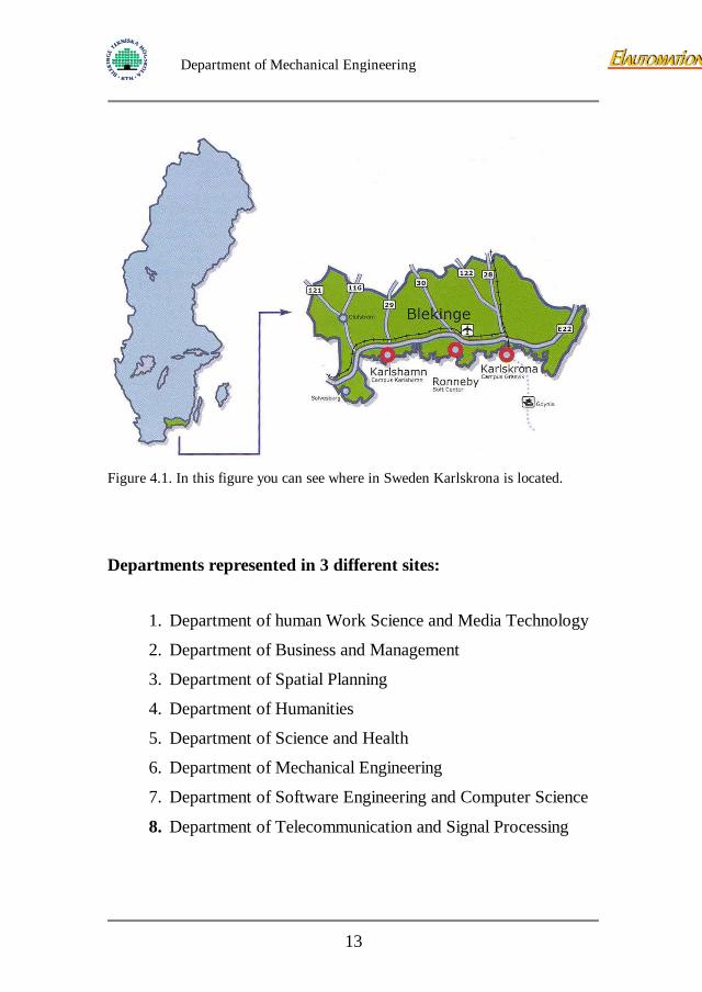
Figure 4.1. In this figure you can see where in Sweden Karlskrona is located.
Departments represented in 3 different sites:
1. Department of human Work Science and Media Technology
2. Department of Business and Management
3. Department of Spatial Planning
4. Department of Humanities
5. Department of Science and Health
6. Department of Mechanical Engineering
7. Department of Software Engineering and Computer Science
8. Department of Telecommunication and Signal Processing
13
Department of Mechanical Engineering
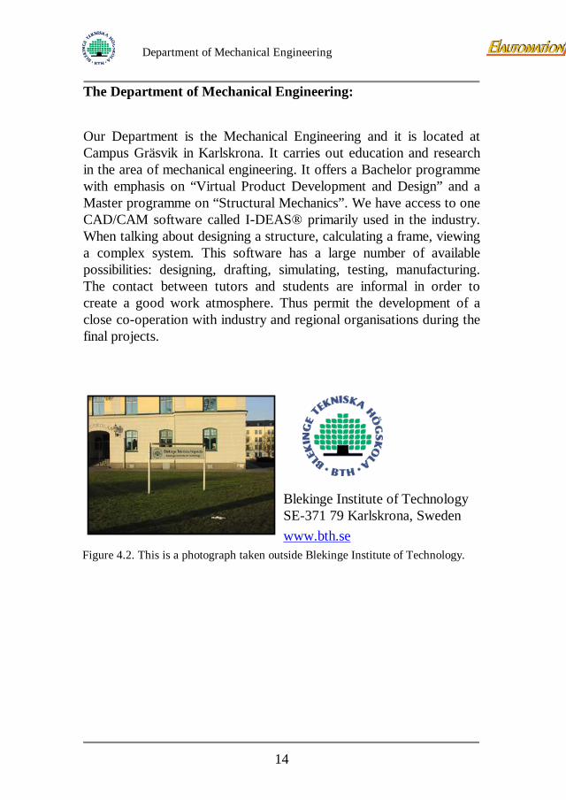
The Department of Mechanical Engineering:
Our Department is the Mechanical Engineering and it is located at Campus Gräsvik in Karlskrona. It carries out education and research in the area of mechanical engineering. It offers a Bachelor programme with emphasis on “Virtual Product Development and Design” and a Master programme on “Structural Mechanics”. We have access to one CAD/CAM software called I-DEAS® primarily used in the industry. When talking about designing a structure, calculating a frame, viewing a complex system. This software has a large number of available possibilities: designing, drafting, simulating, testing, manufacturing. The contact between tutors and students are informal in order to create a good work atmosphere. Thus permit the development of a close co-operation with industry and regional organisations during the final projects.
Blekinge Institute of Technology SE-371 79 Karlskrona, Sweden www.bth.se
Figure 4.2. This is a photograph taken outside Blekinge Institute of Technology.
14
Department of Mechanical Engineering
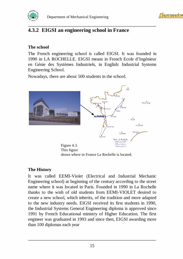
4.3.2 EIGSI an engineering school in France
The school The French engineering school is called EIGSI. It was founded in 1990 in LA ROCHELLE. EIGSI means in French Ecole d’Ingénieur en Génie des Systèmes Industriels, in English: Industrial Systems Engineering School. Nowadays, there are about 500 students in the school.
Figure 4.3. This figure shows where in France La Rochelle is located.
The History It was called EEMI-Violet (Electrical and Industrial Mechanic Engineering school) at beginning of the century according to the street name where it was located in Paris. Founded in 1990 in La Rochelle thanks to the wish of old students from EEMI-VIOLET desired to create a new school, which inherits, of the tradition and more adapted to the new industry needs. EIGSI received its first students in 1990, the Industrial Systems General Engineering diploma is approved since 1991 by French Educational ministry of Higher Education. The first engineer was graduated in 1993 and since then, EIGSI awarding more than 100 diplomas each year
15
Department of Mechanical Engineering
The environment The School is located in La Rochelle on the Atlantic coast, about 500km from Paris. It takes place in the university campus in “Les Minimes” the largest harbour in Europe. Nowadays, the university campus counts 8000 students and EGSI about 500.
The education It is a five years multidisciplinary school; the students integrate the courses just after Baccalaureate (equivalency of the A level) and having no preliminary preparatory cycle integrated into the curriculum. Some students who have had a special course can integrate the school in third years. The courses connect the various traditional scientific fields and ensure a global solution with talking into account all the technical, economic and human components. It constitutes a new approach to circumvent the industrial development. During the five years, the students will be following some lectures, tutorials, practices, and works assignments in this the several fields:
• Mathematics
• Computer science
• Mechanics and Energy
• Mechanical Engineering and material
• Electricity
• Automation
• Communication
• Management
In order to connects their scientific knowledge to the industrials world, the students have to do some training periods:
16
Department of Mechanical Engineering
• In the second or third year: as a technician to discover the industrial world and the worker's conditions.
• During the fourth year: In small groups on industrial study for
six weeks, which students carry out in a company within the framework of an industrial project.
• In the fifth year: Engineering training: five months training
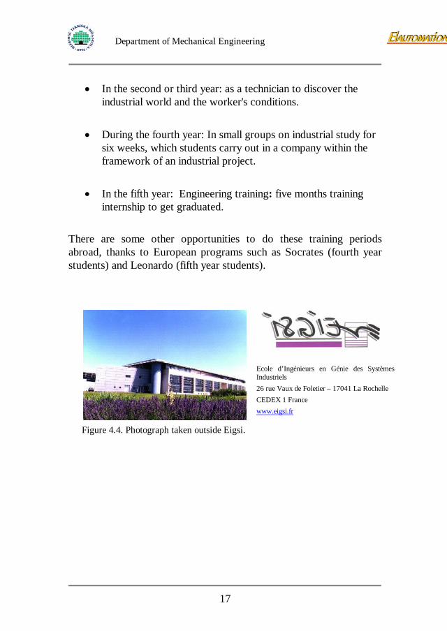
internship to get graduated. There are some other opportunities to do these training periods abroad, thanks to European programs such as Socrates (fourth year students) and Leonardo (fifth year students).
Figure 4.4. Photograph taken outside Eigsi.
Ecole d’Ingénieurs en Génie des Systèmes Industriels 26 rue Vaux de Foletier – 17041 La Rochelle CEDEX 1 France www.eigsi.fr
17
Department of Mechanical Engineering
4.4 Fredy Olsson’s Integrated Product Development In this project we will use a method of integrated product development. Fredy Olsson [1] is the author of this method. 4.4.1 The process of IPD
The general description of this process:
1. Define the need on the market. Our superiors in our project had already defined this.
2. Define the type of the product.
3. The principal construction phase, the first step in this report.
4. The primary construction phase, the second step in this report.
5. Manufacturing design.
6. Final design.
7. Prototype and testing.
The principal construction phase
This part of the process contains:
• Product definition. The product’s containing parts, its tasks, its working surroundings and who are getting in contact with the product.
• Product survey and criterion disposition. We do a background check, are there any existing solutions on the same product and we define all the criterions for the product.
• Compilation of product proposals. We show different solutions which can fulfil our criterions.
• Evaluation of the product proposals. We evaluate the proposals we have and see if they fulfil our criterions.
18
Department of Mechanical Engineering
• Presentation of the final, chosen proposal. The best proposal
will be chosed so we can start work with the next step, the primary construction phase.
The primary construction phase
This part of the process contains:
• Product Concept. Here we show the parts which are included in the product, how they are arranged and some approximately dimensions.
• Component choice. Here all the parts which can be bought are shown. To buy standard components saves time and money.
• Detail construction. Here we design parts which can’t be bought. These parts are special and rare so we need to make them ourselves.
• Manufacturing and testing. We manufacture a final prototype and make some tests to make sure it fulfil our demands. If it doesn’t it will be expensive to make changes this late.
5 PPSHE In Swedish this chapter is called POME. The chapter contain these parts:
The product - an explanation of what the product will perform, which units are involved and the connection between these.
The process - the main process, part processes an their connection and the need.
Surroundings - the places and environments where the product should be used.
The human - who or which become users. And who becomes involved of the product, the human’s relation to the product and the interplay human-product.
The economy – conditions for the economy.
19
Department of Mechanical Engineering
5.1 Product (P) The product is a module design to drive a serving cart forward. The module is supposed to work as a servo in order to relieve the load on the personal pushing the cart. Thereby injures caused by this operation is reduced.
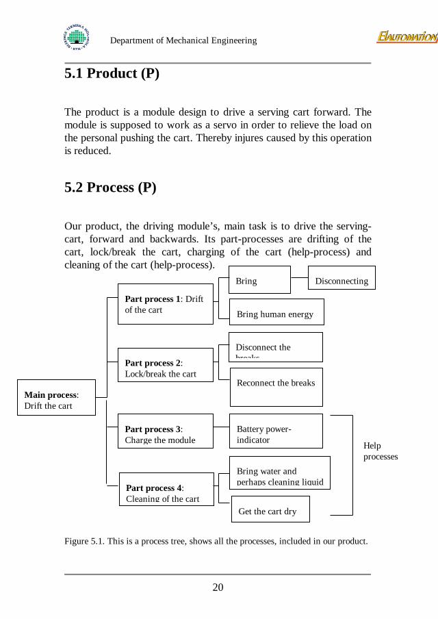
5.2 Process (P) Our product, the driving module’s, main task is to drive the serving-cart, forward and backwards. Its part-processes are drifting of the cart, lock/break the cart, charging of the cart (help-process) and cleaning of the cart (help-process). Figure 5.1. This is a process tree, shows all the processes, included in our product.
Main process: Drift the cart
Part process 2: Lock/break the cart
Part process 1: Drift of the cart
Part process 4: Cleaning of the cart
Part process 3: Charge the module
Battery power-indicator
Bring
Disconnect the breaks
Disconnecting
Bring human energy
Reconnect the breaks
Get the cart dry
Bring water and perhaps cleaning liquid
Help processes
20

Department of Mechanical Engineering
5.3 Surroundings (S) The product will adjacent to the serving cart itself. The whole world is counted as the geographic area and the module must therefore resist all sorts of climate. The module’s working surroundings will be onboard a plane and a kind of industrial hall where they will be recharged, loaded with food or washed.
5.4 Human (H) Air hostess – operator Passenger – involved Airhostess – benefits from the use of the product Airport personal – Negative (recharge of batteries)
The product perform Drives the cart forward Locks the cart when it stops Loads the batteries
The personal performs Plugs in the recharging device into the module Cleans the cart Activate the direction control devices Disengage the module when desired
21
Department of Mechanical Engineering
5.5 Economy (E) The market price, price to customer, is decided to be 5500 SEK without VAT as a maximum price. An ordinary cart cost about 8000 SEK. The cost for assembling the components is allowed to be no more than 1000 SEK. Mounting the module onto the cart isn’t included in this price. The components mustn’t cost more than 2000 SEK.
6 Product survey and criterion disposition
6.1 Product survey There are no current solutions for a module for the flight carts, but there are some existing carts that are manufactured with electric drive. The patents for these carts will not interfere with our product. We heard about a big cart at the hospital that was electric driven. So we went to the hospital to find that this cart was used to deliver newspapers and candy etc. This cart had a good solution; they had installed one motor with one wheel in the centre of the cart. So all the four wheels are free to rotate. Christer Georgsson managed to arrange a meeting at the airport of Ronneby. Here we got access to the carts, where they were standing before take off. The carts were loaded with food and then they were taken to the plane. The forklift truck lifted the carts into the plane, through a sliding door on the side of the stairs.
6.1.1 SAS During an interview with Peter Melander, SAS, we found out some interesting facts about how the carts were used. The daily use of a smaller cart is up to 3 flights a day. The treatment of these carts is
22
Department of Mechanical Engineering
very hard. They are being dragged over thresholds with a height of up to 8 cm. The space inside the plane is very little and the carts may therefore bounce into the walls. Outside the plane they can fall onto the ground causing serious damage. Inside the catering kitchens they are quickly unloaded and reloaded. They are also washed here. We also found out that there are standards about flight equipment that can cause trouble during usage. The feeling we got from SAS is that the carts are being used without any consideration. We did also find out that the manufacturer of the washing equipment is Wexiödisk AB, in Växjö. Results of the Questionnaire Questions seen in Appendix [1 and 2] told us: There is no change in holding positions between the small and the big cart, but if it was really heavy to move the big cart maybe the personal used a hip-push to get the cart moving. Our conclusion is that all three different carts are pushed in the same way, holding the handles with two hands. According to the answers there were no problems controlling the cart, pending on the size of the cart, on the other hand control problem could appear concerning the weight. We also found that on top of the cart a possible basket with bread could be placed. There were no other comments or wishes. Due to the low amount of participants in the survey there is no statistics made of the results. 6.1.2 Wexiödisk AB To get information about how the carts are being washed and data we contacted Wexiödisk AB. There we talked with Gudrun Johansson on the sales department, she sent us all the information about their different washing machines. From these catalogues we could say that the model was a Trolley Washer WD-18CW, we got some criterions from the technical data in the information catalogue see Appendix 3-6.
23
Department of Mechanical Engineering
6.1.3 Iacobucci
In order to receive a drawing with dimensions the company Iacobucci, one of the manufacturers of carts for SAS. We received the drawing from them shown in Appendix 13.
6.2 Criterion and wishes disposition Notice that the wishes are marked with (W). 6.2.1 Functions or performance criterions
1. The module must be able to hold the pressure from the cart (representing a total force of 1100 N).
2. The module shall be easy to control.
3. The module must engage the parking brake automatically.
4. The module must be able to be disengaged, so the cart can be pushed by hand.
5. The module mustn’t disturb the electronics in the plane, Electro Magnetic Compatibility, according to RTCA 160D.
6. The cart with two handles must have the function of “master-slave” on each side.
7. The module must hold for hard treatment, for example transportation between the plane and the wash and when driving over thresholds (the only big threshold is the one when you enter the plane).
8. The module should be equipped with a battery power-indicator. (W)
9. All not-motorized wheels on the cart must remain free to rotate.
24
Department of Mechanical Engineering
10. The stability of the cart should not decrease. (W)
6.2.2 Operation criterions
11. The module mustn’t change the height, width or length of the cart.
12. The module mustn’t change the storing-space in the cart.
13. The module must be waterproof according to the technical specifications on Trolley Washer WD-18CW, see Appendix 3-5.
14. The module should have a life of ten years. 6.2.3 Personal safety criterions
17. The module must comply with existing safety regulations for example “Maskindirektivet, AFS 1994:48”.
6.2.4 Ergonomic criterions
18. The module mustn’t interfere with existing ergonomics.
19. The airhostesses shouldn’t need to perform difficult movements to drive the cart. (W)
6.2.5 Esthetical criterions
20. The module shouldn’t interfere too much with the look of the cart. (W)
21. The module should, if possible, comply with the colour of the existing cart. (W)
25
Department of Mechanical Engineering
6.2.6 General design/production criterions
22. A low weight of the module is desirable. (W)
23. Modularity as far as possible, easy to exchange the different components/details. (W)
24. As few components inside the module as possible. (W)
25. Easy to assemble the module. (W)
26. Low cost is desirable. (W)
27. The module should be as effective as possible concerning the material use. (W)
6.2.7 Manufacturing criterions
28. The module should be designed for different sizes of carts. (W) 6.2.8 Disposal custody, sales and supplies criterions
29. Easy assembling on cart is desirable. (W)
6.2.9 Elimination criterions
30. All the parts should be able to be taken care of in a professional environmental correct way meaning no unusual materials.
31. The cart should be restorable. (W)
26
Department of Mechanical Engineering
6.2.10 Production economical criterions
32. Standard components should be used as far as possible.
33. The components mustn’t cost more than 2000 SEK.
34. The cost for assemble the parts mustn’t be more than 1000 SEK.
6.2.11 Users economical criterions
35. The price to for the customer mustn’t be more than 5500 SEK, without VAT.
6.3 Additional comments In order to limit the time of the project it has been decided that when the following parts are finished, the project is finished:
Full report written including:
Results
Drawings (both 3D and 2D)
We’ll make a model to show the function and outlining.
Parts excluded are the charging of the batteries, cables and the primary part of the steering device. Even small parts as screws and nuts will not be included.
27
Department of Mechanical Engineering
7 Compilation of product proposals for module
7.1 Manner of operation
We have found two ways to operate the cart: 7.1.1 Electric motor The first manner of operation contains an electric motor. Batteries provide the energy needed for the motor/motors. The motor is connected by a transmission to the wheel/wheels. 7.1.2 Compressed air The second manner of operation is a compressor motor. An air pressure tank provides the energy for the motor. The flow is regulated with a valve. Due to safety regulations and economy this principal fails.
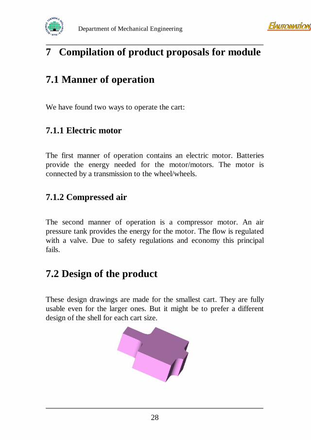
7.2 Design of the product These design drawings are made for the smallest cart. They are fully usable even for the larger ones. But it might be to prefer a different design of the shell for each cart size.
28
Department of Mechanical Engineering
Figure 7.1. This shell shows the maximum volume that is available.
Figure 7.1 shows the maximum volume available underneath the cart, designed for revolving movement of wheels and made to fit with existing brake pedals. This means that the module cannot be bigger than this.
Figure 7.2. This shell shows how the shell can look like when it’s designed.
Figure 7.2 shows an example of the final module shell, just to give a picture of the module outlining. Observe that for the final module changes will be made on the design, to make the driving module and batteries fit inside.
7.3 The products way of construction & primary proposals
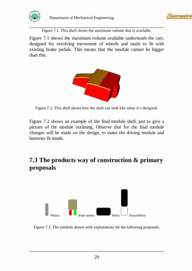
Figure 7.3. The symbols shown with explanations for the following proposals.
29
Department of Mechanical Engineering
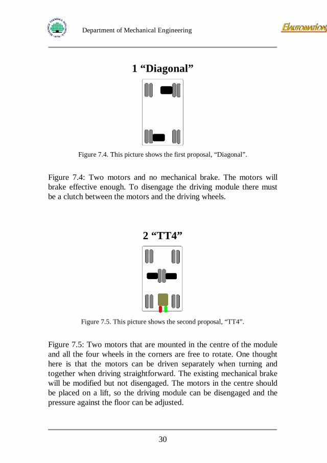
1 “Diagonal”
Figure 7.4. This picture shows the first proposal, “Diagonal”.
Figure 7.4: Two motors and no mechanical brake. The motors will brake effective enough. To disengage the driving module there must be a clutch between the motors and the driving wheels.
2 “TT4”
Figure 7.5. This picture shows the second proposal, “TT4”.
Figure 7.5: Two motors that are mounted in the centre of the module and all the four wheels in the corners are free to rotate. One thought here is that the motors can be driven separately when turning and together when driving straightforward. The existing mechanical brake will be modified but not disengaged. The motors in the centre should be placed on a lift, so the driving module can be disengaged and the pressure against the floor can be adjusted.
30
Department of Mechanical Engineering
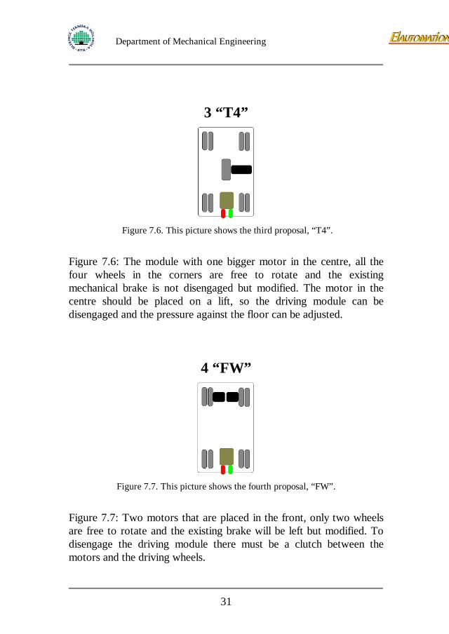
3 “T4”
Figure 7.6. This picture shows the third proposal, “T4”.
Figure 7.6: The module with one bigger motor in the centre, all the four wheels in the corners are free to rotate and the existing mechanical brake is not disengaged but modified. The motor in the centre should be placed on a lift, so the driving module can be disengaged and the pressure against the floor can be adjusted.
4 “FW”
Figure 7.7. This picture shows the fourth proposal, “FW”.
Figure 7.7: Two motors that are placed in the front, only two wheels are free to rotate and the existing brake will be left but modified. To disengage the driving module there must be a clutch between the motors and the driving wheels.
31
Department of Mechanical Engineering
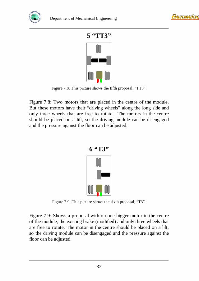
5 “TT3”
Figure 7.8. This picture shows the fifth proposal, “TT3”.
Figure 7.8: Two motors that are placed in the centre of the module. But these motors have their “driving wheels” along the long side and only three wheels that are free to rotate. The motors in the centre should be placed on a lift, so the driving module can be disengaged and the pressure against the floor can be adjusted.
6 “T3”
Figure 7.9. This picture shows the sixth proposal, “T3”.
Figure 7.9: Shows a proposal with on one bigger motor in the centre of the module, the existing brake (modified) and only three wheels that are free to rotate. The motor in the centre should be placed on a lift, so the driving module can be disengaged and the pressure against the floor can be adjusted.
32
Department of Mechanical Engineering
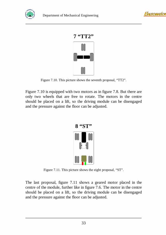
7 “TT2”
Figure 7.10. This picture shows the seventh proposal, “TT2”.
Figure 7.10 is equipped with two motors as in figure 7.8. But there are only two wheels that are free to rotate. The motors in the centre should be placed on a lift, so the driving module can be disengaged and the pressure against the floor can be adjusted.
8 “ST”
Figure 7.11. This picture shows the eight proposal, “ST”.
The last proposal, figure 7.11 shows a geared motor placed in the centre of the module, further like in figure 7.6. The motor in the centre should be placed on a lift, so the driving module can be disengaged and the pressure against the floor can be adjusted.
33
Department of Mechanical Engineering
8 Evaluation of the product proposals of module
8.1 Advantages and disadvantages of the proposals Below we list about what’s good or bad with the different proposals. Advantages are marked with (A) and disadvantages are marked with (D).
8.1.1 “Diagonal” (1)
(A):
- Much space left for batteries
(D): - Only two wheels are free to rotate → hard to make
narrow turns
- Two motors
- Clutch is needed
- Brakes?
8.1.2 “TT4” (2)
(A):
- Four wheels, which are free to rotate
- Motor brake
34
Department of Mechanical Engineering
- The existing brake is used and will also be used to
raise and lower the motor module
(D):
- Two motors
- A lift is needed to engage/disengage the motor
- Separate steering-device on the two motors
8.1.3 “T4” (3)
(A):
- Four wheels, which are free to rotate
- Motor brake
- The existing brake is used and will also be used to raise and lower the motor module
(D):
- The size/volume of the motor?
8.1.4 “FW” (4)
(A):
- We can use the existing brake
- The cart will be easy to control when going straight forward
(D):
35
Department of Mechanical Engineering
- Not four free wheels → hard to make narrow turns
- Two motors
- Clutch is needed
8.1.5 “TT3” (5)
(A):
- Easy to turn
- The cart will be easy to control when going straight forward
- The existing brake is used and will also be used to raise and lower the motor module
(D):
- Two motors
- Separate steering
- The cart will be easy to tip
8.1.6 “T3” (6)
(A):
- The existing brake is used and will also be used to raise and lower the motor module
(D):
- Choice of the motor?
- The cart will be easy to tip
36
Department of Mechanical Engineering
8.1.7 “TT2” (7)
(A):
- The cart will be easy to control when going straight forward
- Easy to turn
(D):
- Two motors
- The cart will be easy to tip
- No existing brake
- Clutch is needed
- Instability sideways
8.1.8 “ST” (8)
(A):
- The existing brake is used and will also be used to raise and lower the motor module
- Four wheels are free to rotate
- Motor brake
(D):
- Motor volume?
- Distance between the driving wheels
37
Department of Mechanical Engineering
8.2 Evaluation The evaluations of the proposals are, according to the Fredy Olsson-model, subdivided in three steps: Primary evaluation: many proposals, which are compared to the main criterions, if they don’t fulfil these they fall out. Intermediate evaluation: further development of the proposals and a more detailed evaluation Final evaluation: only two to four proposals will exist, on these proposals calculations and principal tests will be performed. 8.2.1 Primary evaluation In this stage we compare the demands with our different proposals, are there any proposals that don’t fulfil our demands they fall out. Technical demands - The module must be able to hold the pressure from the cart (max 1100 N). - The module shall be easy to control. - The module must be self-locking and work as a brake. - The module must be able to be disengaged, so the cart can be pushed by hand. - The module mustn’t disturb the electronics in the plane, Electro Magnetic Compatibility. - The cart with two handles must have the function of “master and slave” on each side.
38
Department of Mechanical Engineering
- The module must hold for hard treatment, for example transportation between the plane and the wash and when driving over thresholds (the only big threshold is the one when you enter the plane). - The module mustn’t change the height, width or length of the cart. - The module mustn’t change the storing-space in the cart. - The module must be waterproof according to IP 56 (SS ENC 60529). - The module should have a life of ten years. - The module must resist the 85-degree Celsius water that is used to wash the cart. - The module must resist the pressure from the water that the washing machine produces, 0.3 Mpa/30litre/min. - The module must comply with existing safety regulations. - The module mustn’t interfere with existing ergonomics. - All the parts should be able to be taken care of in a professional environmental correct way meaning no unusual material. Economical demands - Standard components should be used as far as possible. - The components mustn’t cost more than 2000 SEK. - The cost for assemble the parts mustn’t be more than 1000 SEK. - The price to for the customer mustn’t be more than 5500 SEK, without VAT. Below you can see a solution classification according to the “direct group method”.
39
Department of Mechanical Engineering
TECHNICAL DEMANDS Group scale
6 fulfil the demands for certain
5
4 probably fulfil the demands
3
2 hardly fulfil the demands
1
0 do not fulfil the demands ECONOMICAL DEMANDS
Group scale 6 fulfil the demands for certain
5
4 probably fulfil the demands
3
2 hardly fulfil the demands
1
0 do not fulfil the demands
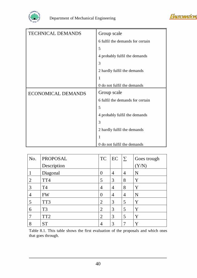
No. PROPOSAL
Description TC EC ∑ Goes trough
(Y/N) 1 Diagonal 0 4 4 N 2 TT4 5 3 8 Y 3 T4 4 4 8 Y 4 FW 0 4 4 N 5 TT3 2 3 5 Y 6 T3 2 3 5 Y 7 TT2 2 3 5 Y 8 ST 4 3 7 Y Table 8.1. This table shows the first evaluation of the proposals and which ones that goes through.
40
Department of Mechanical Engineering
Proposals number one (Diagonal) and number four (FW) don’t fulfil the main criteria 9 (all not-motorized wheels on the cart must remain free to rotate). So these two proposals won’t go through to the next evaluation.
8.2.2 Intermediate evaluation
We went to “Coop Forum”, a supermarket in Karlskrona, to take a look on their carts. They have storing carts with only three wheels and this size gives no problem but if they would be shorter, like our carts, we all agreed that it would be problems with the stability. Proposals number six (T3) and number seven (TT2) does not fulfil the main criteria 10 because of the instability. Also number five (TT3) will fall for this criteria depending on how the cart will be loaded with its contents. The remaining proposals are number two (TT4), number three (T4) and number eight (ST). 8.2.3 Final evaluation
Final assessment of wishes according to the ”compare method in pairs” A: The module should be equipped with a battery power-indicator B: The airhostesses shouldn’t need to perform difficult movements to drive the cart C: The module shouldn’t interfere too much with the look of the cart D: The module should, if possible, comply with the colour of the existing cart E: A low weight of the module is desirable F: Modularity as far as possible, easy to exchange the different components/details
41
Department of Mechanical Engineering
G: As few components inside the module as possible H: Easy to assemble the module I: Low cost is desirable J: The module should be as effective as possible concerning the material use K: The module should be designed for different sizes of carts L: Easy assembling on cart is desirable M: The cart should be restorable N: The stability of the cart should not decrease
42
Department of Mechanical Engineering
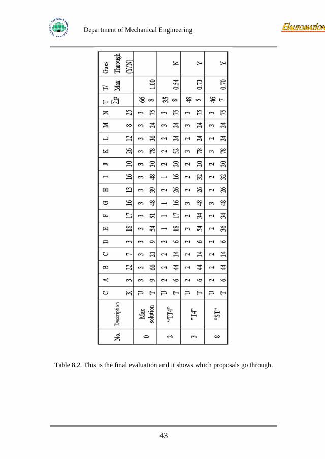
Table 8.2. This is the final evaluation and it shows which proposals go through.
43
Department of Mechanical Engineering
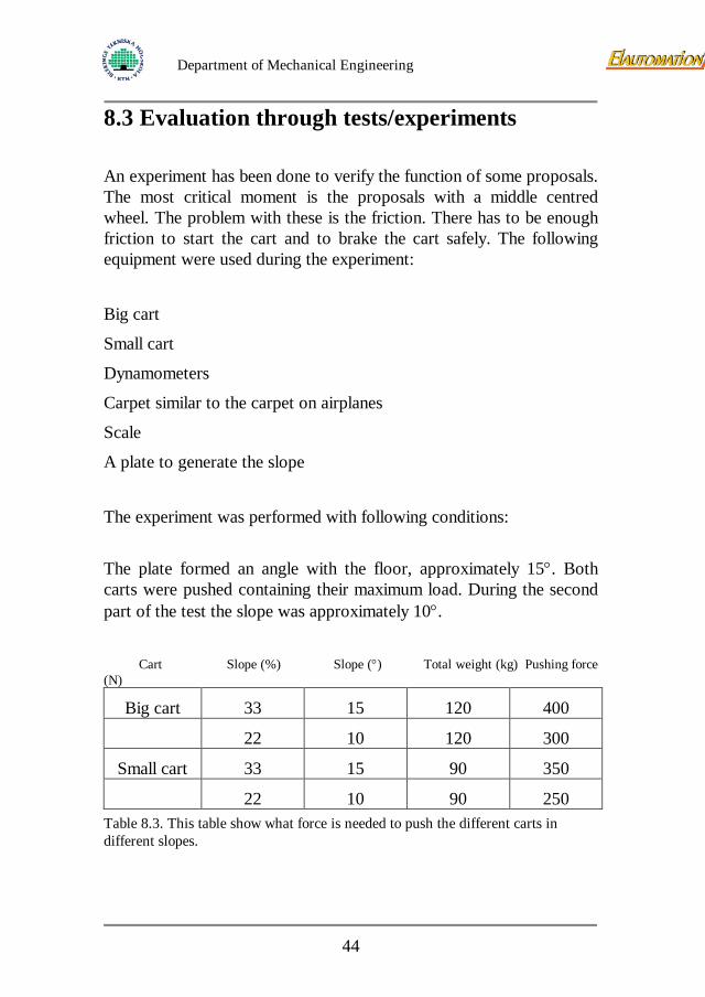
8.3 Evaluation through tests/experiments An experiment has been done to verify the function of some proposals. The most critical moment is the proposals with a middle centred wheel. The problem with these is the friction. There has to be enough friction to start the cart and to brake the cart safely. The following equipment were used during the experiment:
Big cart
Small cart
Dynamometers
Carpet similar to the carpet on airplanes
Scale
A plate to generate the slope
The experiment was performed with following conditions: The plate formed an angle with the floor, approximately 15°. Both carts were pushed containing their maximum load. During the second part of the test the slope was approximately 10°. Cart Slope (%) Slope (°) Total weight (kg) Pushing force (N)
Big cart 33 15 120 400
22 10 120 300
Small cart 33 15 90 350
22 10 90 250 Table 8.3. This table show what force is needed to push the different carts in different slopes.
44
Department of Mechanical Engineering
Results from the experiment: During the product survey the highest slope found when serving was 22%. Dimensioning the motor for the higher slope will probably secure the module from unknown types of use. The highest needed pushing force is 400 N. The reliability of the test is good. The carpet used has a surface, which is quiet thicker, than the carpet used in a plane.
8.4 Second test The need for the brake to withstand the pressure during take-off has also been tested. The wheel that is possible to use on the proposals with a middle centred wheel is similar to the existing wheels on the cart. Therefore the small cart was used in this test. The test was performed on the carpet with no slope what so ever. Because of the ”primitive” equipment the test wasn’t fulfilled. When the pushing force exceeded 400 N the carpet started to move. Calculations for the big cart fully loaded standing in a slope of 33% shows that the brake has to hold for maximum 300 N. The test-results give 400 N and then the carpet starts to move. The approximation with reality is good except for the surface of the carpet. It’s possible that the carpet inside a plane is more slippery. The results from these two tests are being used in further calculations.
45
Department of Mechanical Engineering
8.4.1 Evaluation through calculations The first approximation of the necessary power to drive the big cart
Data:
Max gross weight 90kg
Max empty weight 27kg
Total weight 117 Kg
We use the Dynamical Mechanical Principal δ∑ = mF (1)
According to the plan organisation we wanted to use 1s to accelerate to the max speed, about 3km/h:
2
3
/83,03600
103sm
dtdv
=×
==δ (2)
Using result from (2) in equation (1)
NFa 6,9983,0120 =×= (3)
This is the force, which is necessary to drive the cart without friction and slope. We have done many tests about ability to move the cart on different carpets with a slope about 30%: We need to have a force about 400N.
We can now calculate the necessary power to drive the cart on the carpet: Notice that the acceleration and the speed have the same value because of the acceleration time 1s.
46

Department of Mechanical Engineering
vFP ×= (4)
Using the result from (2) in equation (4)
WP 33283,0400 =×=
Now you can calculate the torque to drive the cart:
If we decided to use a eight-centimetre diameter wheels:
r×π2 (5), gives the distance per rotation
Using the equation (5)
rm /25,010422=××
−π (6)
With a speed of 0,83 m/s: rps32,325,083,0
= (6)
f×= πω 2 (7)
Using result from equation (6) in equation (7)
srad /86,2032,32 =×= πω (8)
ω×= vMP (9)
Torque from the out axle of the reducer
NmPM v 92,1586,20
332===
ω (9)
47
Department of Mechanical Engineering
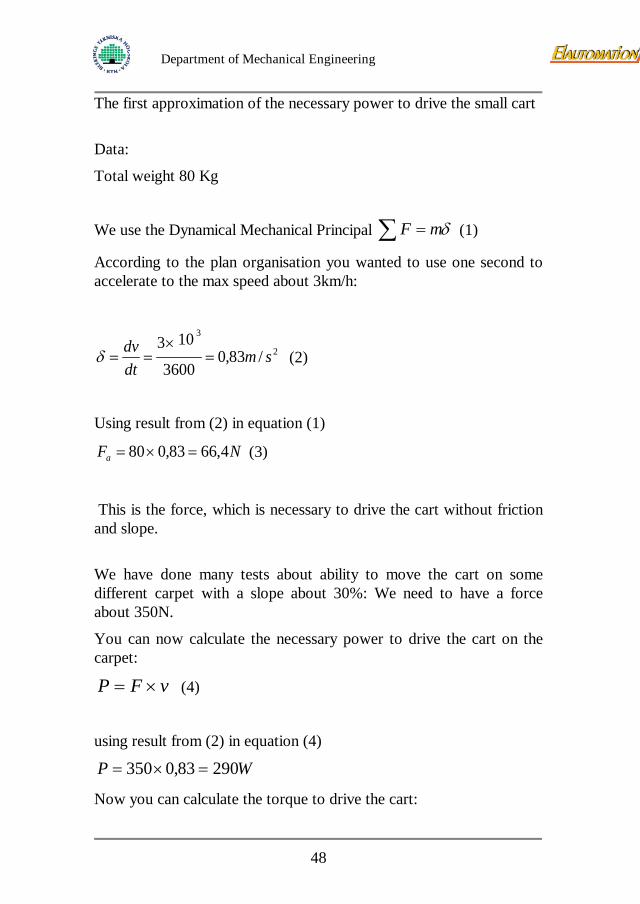
The first approximation of the necessary power to drive the small cart Data:
Total weight 80 Kg
We use the Dynamical Mechanical Principal δ∑ = mF (1)
According to the plan organisation you wanted to use one second to accelerate to the max speed about 3km/h:
2
3
/83,03600
103sm
dtdv
=×
==δ (2)
Using result from (2) in equation (1)
NFa 4,6683,080 =×= (3)
This is the force, which is necessary to drive the cart without friction and slope. We have done many tests about ability to move the cart on some different carpet with a slope about 30%: We need to have a force about 350N.
You can now calculate the necessary power to drive the cart on the carpet:
vFP ×= (4)
using result from (2) in equation (4)
WP 29083,0350 =×=
Now you can calculate the torque to drive the cart:
48
Department of Mechanical Engineering
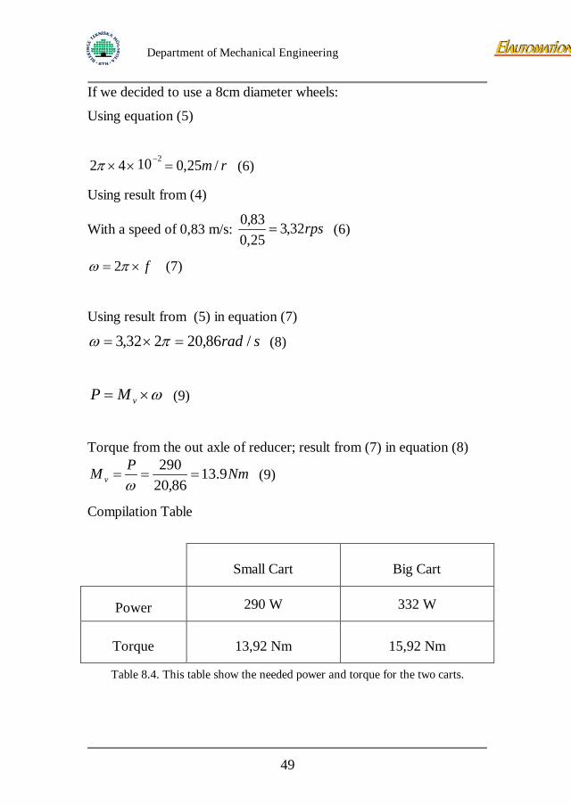
If we decided to use a 8cm diameter wheels:
Using equation (5)
rm /25,01042 2 =×× −π (6)
Using result from (4)
With a speed of 0,83 m/s: rps32,325,083,0
= (6)
f×= πω 2 (7)
Using result from (5) in equation (7)
srad /86,20232,3 =×= πω (8)
ω×= vMP (9)
Torque from the out axle of reducer; result from (7) in equation (8)
NmPM v 9.1386,20
290===
ω (9)
Compilation Table
Small Cart Big Cart
Power 290 W 332 W
Torque 13,92 Nm 15,92 Nm
Table 8.4. This table show the needed power and torque for the two carts.
49
Department of Mechanical Engineering
Conclusion: Finally with the efficiency of the reducer and its reduction rate we can determinate the motor torque and rotation speed for the calculated power. This is an approximation because we don’t use the inertial and the friction coefficient and we use some experimental result but this enough for determine the first prototype.
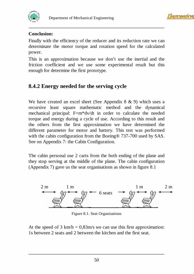
8.4.2 Energy needed for the serving cycle We have created an excel sheet (See Appendix 8 & 9) which uses a recursive least square mathematic method and the dynamical mechanical principal: F=m*dv/dt in order to calculate the needed torque and energy during a cycle of use. According to this result and the others from the first approximation we have determined the different parameter for motor and battery. This test was performed with the cabin configuration from the Boeing® 737-700 used by SAS. See on Appendix 7: the Cabin Configuration. The cabin personal use 2 carts from the both ending of the plane and they stop serving at the middle of the plane. The cabin configuration (Appendix 7) gave us the seat organisations as shown in figure 8.1
Figure 8.1. Seat Organisations
At the speed of 3 km/h = 0,83m/s we can use this first approximation: 1s between 2 seats and 2 between the kitchen and the first seat.
6 seats 2 m 2 m 1 m 1 m
50
Department of Mechanical Engineering
Cycle Time of use:
• 2s in forward motion between the kitchen and the first seat.
• 1s between 2 seats during 10 seats to the middle of the plane.
• 10s break for serving the food
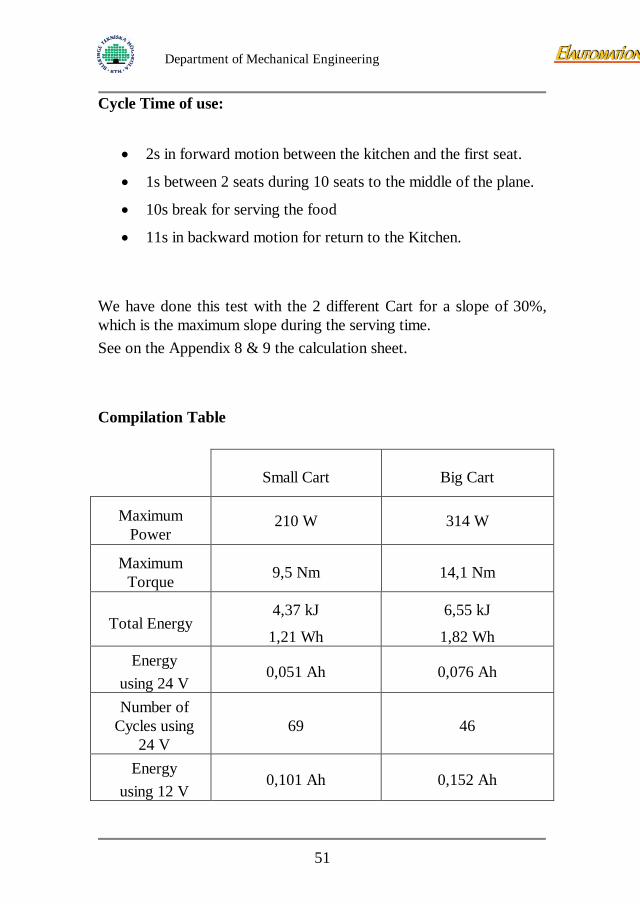
• 11s in backward motion for return to the Kitchen. We have done this test with the 2 different Cart for a slope of 30%, which is the maximum slope during the serving time. See on the Appendix 8 & 9 the calculation sheet. Compilation Table
Small Cart Big Cart
Maximum Power
210 W 314 W
Maximum Torque 9,5 Nm 14,1 Nm
Total Energy 4,37 kJ
1,21 Wh
6,55 kJ
1,82 Wh Energy
using 24 V 0,051 Ah 0,076 Ah
Number of Cycles using
24 V 69 46
Energy using 12 V
0,101 Ah 0,152 Ah
51
Department of Mechanical Engineering
Number of
Cycles using 12 V
35 23
Table 8.5. This table show the energy consumption.
The maximum discharge is calculated for less than 50% of the capacity, for the deepest discharge, the battery could be damage. This result is for a 7Ah battery, which fulfil our demand. Conclusion This calculation is an approximation because the wheels friction and the air penetration are missed. Furthermore these results are enough precise to fulfil our demands. These results permitted us to define the motor and battery parameters in order to make the good choice. We have to choose components, which fulfil these criterions.
9 Lift development
9.1 Function of the lift Our thoughts are to make the module able to work as planned: The module is supposed to be self-braking when the handles are inactivated and move when controlled by the handles, still should the cart be able to move as present when the brake is deactivated. This function can be reached by two different methods: Clutch: Between the motor and driving wheel a clutch is placed and the existing brake is used for parking brake, this method demands either a lever or pedal to control the clutch.
52
Department of Mechanical Engineering
Lift: The driving wheel is lifted up when existing pedal for deactivating brake is pushed, thereby the motor brake is deactivated and since the brake on the existing wheels is permanently disabled the cart can move freely. The motor brake is used both for self-brake and parking brake of the cart. The driving wheel is making contact with the floor when pushing down existing pedal for activating the brake. According to the limited space for lever or new pedal the clutch method will be rejected.
9.2 Criterion disposition for lift The same criterions as for the module including the criterions below will be valid for the lift. Wishes marked (W) and demands marked (D).
• Plain construction (W)
• Sturdy construction (W)
• Compact construction (W)
• Use existing pedals (D)
• Reliable construction (D)
• Fit according to space (D)
9.3 Lift proposals
To protect the driving module against threshold damages we will add a suspension to all the proposals.
53
Department of Mechanical Engineering
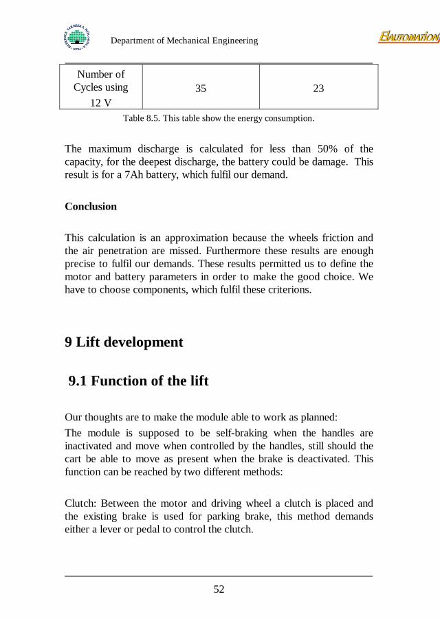
Figure 9.1. Shows the “twin”.
Proposal no.1 (figure 9.1): the “Twin”, using the principle of deformable parallelogram. When pushing the pedal you engage the drive module by deformation of the parallelogram. The lifting module could be frail sideways and claims much space.
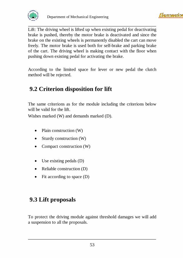
Figure 9.2. Shows the “slider”.
Proposal no.2 (figure 9.2): the “Slider”. The slope between the oblong hole and the plate of the cart allows the lifting of the motor reducer. Easy to manufacture and made as a sturdy construction.
54
Department of Mechanical Engineering
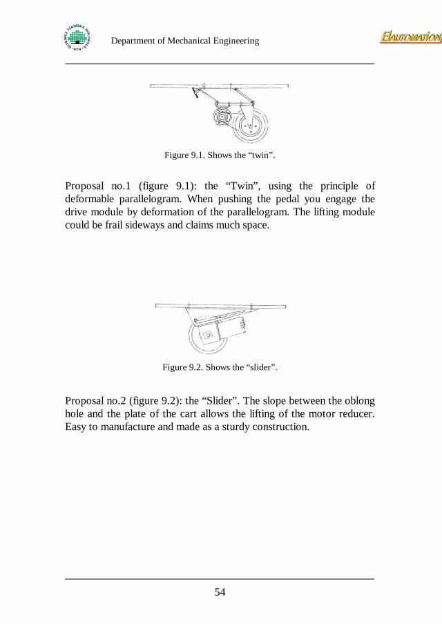
Figure 9.3. Shows the “big belt”.
Proposal no.3 (figure 9.3): the “Big Belt”. Similar function as “Slider”, but here only the wheel is moved. Sturdy construction, easy to manufacture.
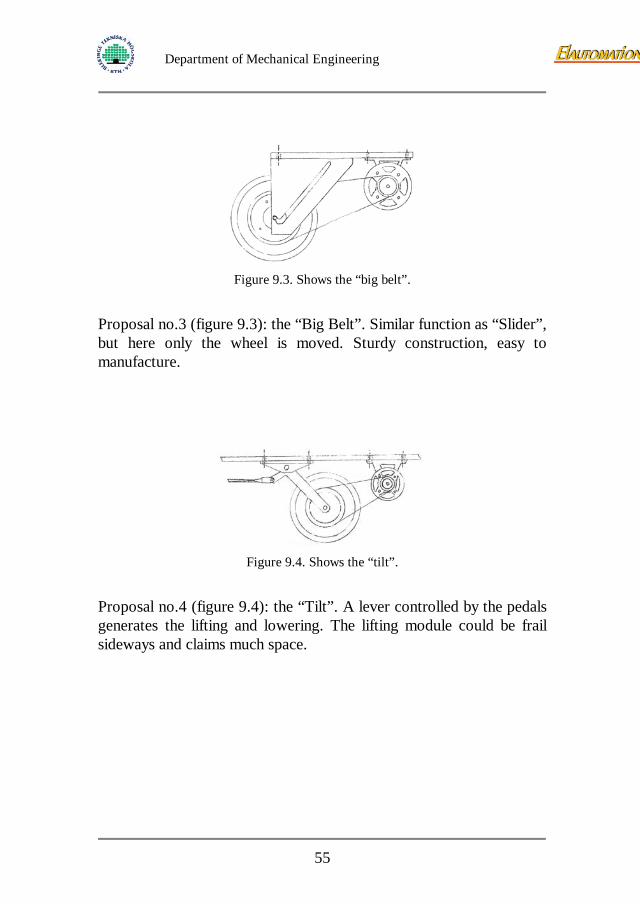
Figure 9.4. Shows the “tilt”.
Proposal no.4 (figure 9.4): the “Tilt”. A lever controlled by the pedals generates the lifting and lowering. The lifting module could be frail sideways and claims much space.
55
Department of Mechanical Engineering
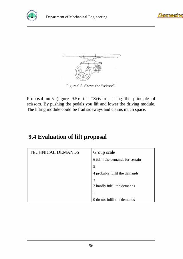
Figure 9.5. Shows the “scissor”.
Proposal no.5 (figure 9.5): the “Scissor”, using the principle of scissors. By pushing the pedals you lift and lower the driving module. The lifting module could be frail sideways and claims much space.
9.4 Evaluation of lift proposal
TECHNICAL DEMANDS
Group scale 6 fulfil the demands for certain
5
4 probably fulfil the demands
3 2 hardly fulfil the demands
1
0 do not fulfil the demands
56
Department of Mechanical Engineering
ECONOMICAL DEMANDS
Group scale 6 fulfil the demands for certain 5
4 probably fulfil the demands
3 2 hardly fulfil the demands
1 0 do not fulfil the demands
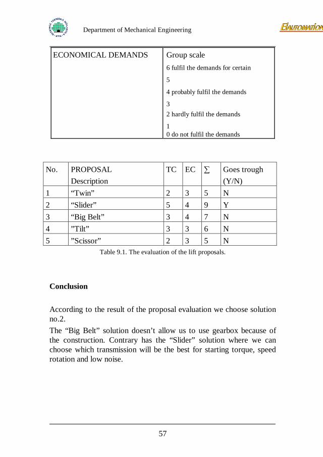
No. PROPOSAL Description
TC EC ∑ Goes trough (Y/N)
1 “Twin” 2 3 5 N 2 “Slider” 5 4 9 Y 3 “Big Belt” 3 4 7 N 4 ”Tilt” 3 3 6 N 5 ”Scissor” 2 3 5 N
Table 9.1. The evaluation of the lift proposals.
Conclusion According to the result of the proposal evaluation we choose solution no.2. The “Big Belt” solution doesn’t allow us to use gearbox because of the construction. Contrary has the “Slider” solution where we can choose which transmission will be the best for starting torque, speed rotation and low noise.
57
Department of Mechanical Engineering
10 Steering device development
10.1 Function of steering device The function is to control the power to the motor. The device mustn’t be able to steer the cart, just control the forward and backward movement. It’s desirable that the steering device has the same function as a servo. When the cabin personal start to push the cart the motor helps proportional to the pushing force. On the big carts where two devices are needed, one on each handle, their function in between should be “master and slave”. During a stop both devices goes high. The device first activated becomes master and the other becomes slave.
10.2 Criterions for steering device The same criterions as for the module inclusive the criterions below will be valid for the steering device. Wishes marked (W) and demands marked (D).
• Safe construction (D)
• Easy to control (W)
• Sturdy construction (W)
• Reliable construction (W)
• Servo function (W)
58
Department of Mechanical Engineering
10.3 Steering device proposals 10.3.1 Manner of operation 5 different ways to control the power to the motor has been found. Switches can be both analogue and digital.
• Thread stretching device
• Toggle switch
• Revolving switch
• Slide control switch
• Micro gap switch
10.3.2 Proposals
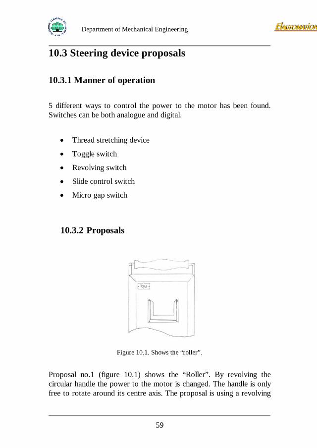
Figure 10.1. Shows the “roller”.
Proposal no.1 (figure 10.1) shows the “Roller”. By revolving the circular handle the power to the motor is changed. The handle is only free to rotate around its centre axis. The proposal is using a revolving
59
Department of Mechanical Engineering
switch and therefore the regulation is variable. This solution cannot be used a servo.
Figure 10.2. Shows the “button”.
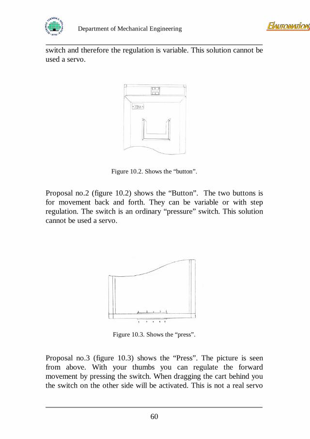
Proposal no.2 (figure 10.2) shows the “Button”. The two buttons is for movement back and forth. They can be variable or with step regulation. The switch is an ordinary “pressure” switch. This solution cannot be used a servo.
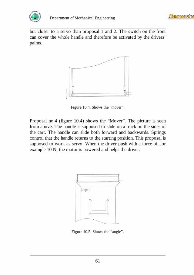
Figure 10.3. Shows the “press”.
Proposal no.3 (figure 10.3) shows the “Press”. The picture is seen from above. With your thumbs you can regulate the forward movement by pressing the switch. When dragging the cart behind you the switch on the other side will be activated. This is not a real servo
60
Department of Mechanical Engineering
but closer to a servo than proposal 1 and 2. The switch on the front can cover the whole handle and therefore be activated by the drivers’ palms.
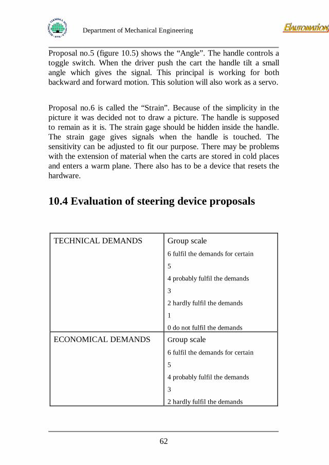
Figure 10.4. Shows the “mover”.
Proposal no.4 (figure 10.4) shows the “Mover”. The picture is seen from above. The handle is supposed to slide on a track on the sides of the cart. The handle can slide both forward and backwards. Springs control that the handle returns to the starting position. This proposal is supposed to work as servo. When the driver push with a force of, for example 10 N, the motor is powered and helps the driver.
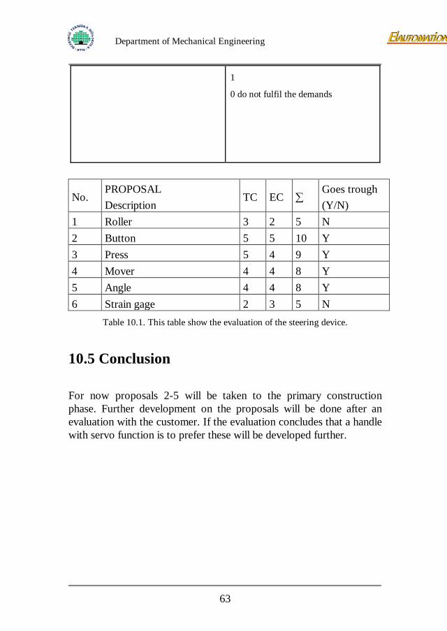
Figure 10.5. Shows the “angle”.
61
Department of Mechanical Engineering
Proposal no.5 (figure 10.5) shows the “Angle”. The handle controls a toggle switch. When the driver push the cart the handle tilt a small angle which gives the signal. This principal is working for both backward and forward motion. This solution will also work as a servo.
Proposal no.6 is called the “Strain”. Because of the simplicity in the picture it was decided not to draw a picture. The handle is supposed to remain as it is. The strain gage should be hidden inside the handle. The strain gage gives signals when the handle is touched. The sensitivity can be adjusted to fit our purpose. There may be problems with the extension of material when the carts are stored in cold places and enters a warm plane. There also has to be a device that resets the hardware.
10.4 Evaluation of steering device proposals
TECHNICAL DEMANDS
Group scale 6 fulfil the demands for certain
5
4 probably fulfil the demands
3
2 hardly fulfil the demands
1
0 do not fulfil the demands
ECONOMICAL DEMANDS
Group scale
6 fulfil the demands for certain
5
4 probably fulfil the demands
3
2 hardly fulfil the demands
62
Department of Mechanical Engineering
1
0 do not fulfil the demands
No. PROPOSAL Description
TC EC ∑ Goes trough (Y/N)
1 Roller 3 2 5 N 2 Button 5 5 10 Y 3 Press 5 4 9 Y 4 Mover 4 4 8 Y 5 Angle 4 4 8 Y 6 Strain gage 2 3 5 N
Table 10.1. This table show the evaluation of the steering device.
10.5 Conclusion For now proposals 2-5 will be taken to the primary construction phase. Further development on the proposals will be done after an evaluation with the customer. If the evaluation concludes that a handle with servo function is to prefer these will be developed further.
63
Department of Mechanical Engineering
11 Presentation of final proposal The chosen proposals will be presented with picture and explanatory text. These proposals will be further developed in the next phase, the primary construction phase. The principals will be presented in order of appearance in the report.
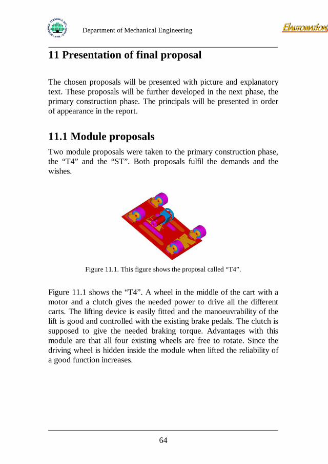
11.1 Module proposals Two module proposals were taken to the primary construction phase, the “T4” and the “ST”. Both proposals fulfil the demands and the wishes.
Figure 11.1. This figure shows the proposal called “T4”.
Figure 11.1 shows the “T4”. A wheel in the middle of the cart with a motor and a clutch gives the needed power to drive all the different carts. The lifting device is easily fitted and the manoeuvrability of the lift is good and controlled with the existing brake pedals. The clutch is supposed to give the needed braking torque. Advantages with this module are that all four existing wheels are free to rotate. Since the driving wheel is hidden inside the module when lifted the reliability of a good function increases.
64
Department of Mechanical Engineering
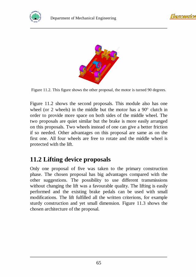
Figure 11.2. This figure shows the other proposal, the motor is turned 90 degrees.
Figure 11.2 shows the second proposals. This module also has one wheel (or 2 wheels) in the middle but the motor has a 90° clutch in order to provide more space on both sides of the middle wheel. The two proposals are quiet similar but the brake is more easily arranged on this proposals. Two wheels instead of one can give a better friction if so needed. Other advantages on this proposal are same as on the first one. All four wheels are free to rotate and the middle wheel is protected with the lift.
11.2 Lifting device proposals Only one proposal of five was taken to the primary construction phase. The chosen proposal has big advantages compared with the other suggestions. The possibility to use different transmissions without changing the lift was a favourable quality. The lifting is easily performed and the existing brake pedals can be used with small modifications. The lift fulfilled all the written criterions, for example sturdy construction and yet small dimension. Figure 11.3 shows the chosen architecture of the proposal.
65
Department of Mechanical Engineering
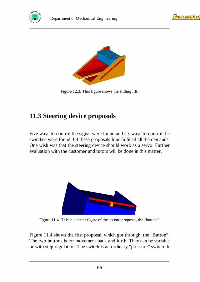
Figure 12.3. This figure shows the sliding lift.
11.3 Steering device proposals Five ways to control the signal were found and six ways to control the switches were found. Of these proposals four fulfilled all the demands. One wish was that the steering device should work as a servo. Further evaluation with the customer and tutors will be done in this matter.
Figure 11.4. This is a better figure of the second proposal, the “button”.
Figure 11.4 shows the first proposal, which got through, the “Button”. The two buttons is for movement back and forth. They can be variable or with step regulation. The switch is an ordinary “pressure” switch. It
66
Department of Mechanical Engineering
is an easy construction and the components aren’t expensive. The understanding of how the steering device is controlled is also very easy. The problem is that this cannot work as a servo.
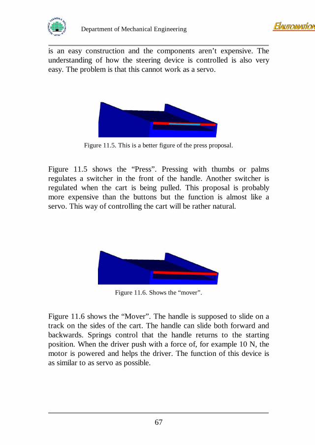
Figure 11.5. This is a better figure of the press proposal.
Figure 11.5 shows the “Press”. Pressing with thumbs or palms regulates a switcher in the front of the handle. Another switcher is regulated when the cart is being pulled. This proposal is probably more expensive than the buttons but the function is almost like a servo. This way of controlling the cart will be rather natural.
Figure 11.6. Shows the “mover”.
Figure 11.6 shows the “Mover”. The handle is supposed to slide on a track on the sides of the cart. The handle can slide both forward and backwards. Springs control that the handle returns to the starting position. When the driver push with a force of, for example 10 N, the motor is powered and helps the driver. The function of this device is as similar to as servo as possible.
67
Department of Mechanical Engineering
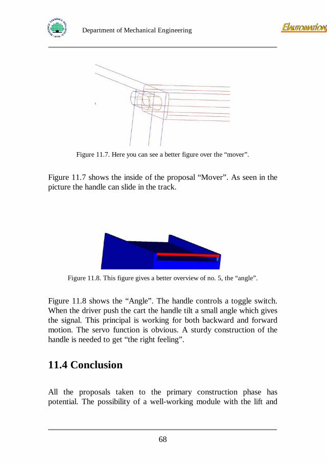
Figure 11.7. Here you can see a better figure over the “mover”.
Figure 11.7 shows the inside of the proposal “Mover”. As seen in the picture the handle can slide in the track.
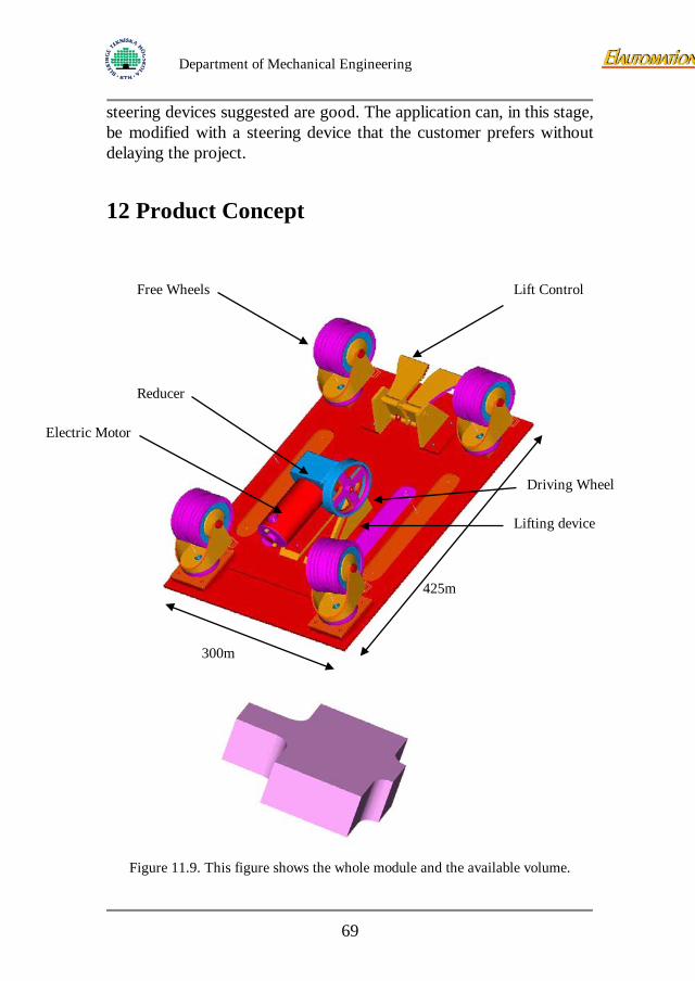
Figure 11.8. This figure gives a better overview of no. 5, the “angle”.
Figure 11.8 shows the “Angle”. The handle controls a toggle switch. When the driver push the cart the handle tilt a small angle which gives the signal. This principal is working for both backward and forward motion. The servo function is obvious. A sturdy construction of the handle is needed to get “the right feeling”.
11.4 Conclusion All the proposals taken to the primary construction phase has potential. The possibility of a well-working module with the lift and
68
Department of Mechanical Engineering
steering devices suggested are good. The application can, in this stage, be modified with a steering device that the customer prefers without delaying the project.
12 Product Concept
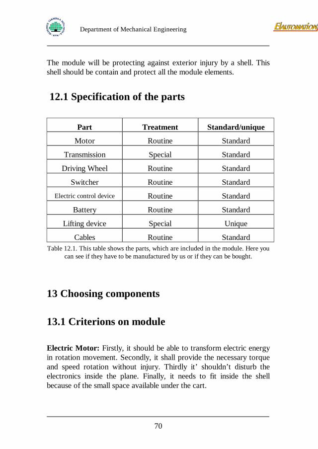
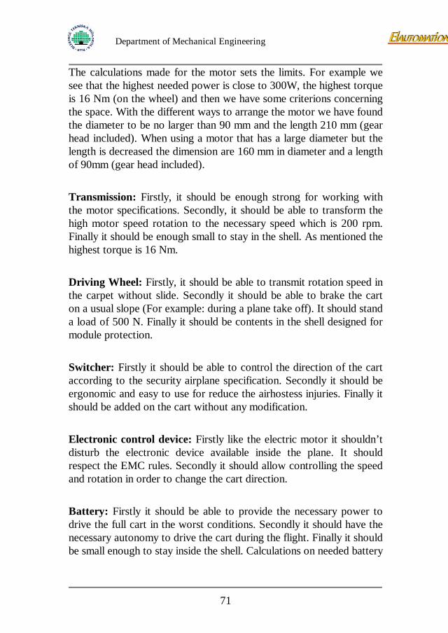
Figure 11.9. This figure shows the whole module and the available volume.
425m
300m
Electric Motor
Reducer
Free Wheels
Lifting device
Driving Wheel
Lift Control
69
Department of Mechanical Engineering
The module will be protecting against exterior injury by a shell. This shell should be contain and protect all the module elements.
12.1 Specification of the parts
Part Treatment Standard/unique
Motor Routine Standard
Transmission Special Standard
Driving Wheel Routine Standard
Switcher Routine Standard
Electric control device Routine Standard
Battery Routine Standard
Lifting device Special Unique
Cables Routine Standard Table 12.1. This table shows the parts, which are included in the module. Here you
can see if they have to be manufactured by us or if they can be bought.
13 Choosing components
13.1 Criterions on module Electric Motor: Firstly, it should be able to transform electric energy in rotation movement. Secondly, it shall provide the necessary torque and speed rotation without injury. Thirdly it’ shouldn’t disturb the electronics inside the plane. Finally, it needs to fit inside the shell because of the small space available under the cart.
70
Department of Mechanical Engineering
The calculations made for the motor sets the limits. For example we see that the highest needed power is close to 300W, the highest torque is 16 Nm (on the wheel) and then we have some criterions concerning the space. With the different ways to arrange the motor we have found the diameter to be no larger than 90 mm and the length 210 mm (gear head included). When using a motor that has a large diameter but the length is decreased the dimension are 160 mm in diameter and a length of 90mm (gear head included). Transmission: Firstly, it should be enough strong for working with the motor specifications. Secondly, it should be able to transform the high motor speed rotation to the necessary speed which is 200 rpm. Finally it should be enough small to stay in the shell. As mentioned the highest torque is 16 Nm. Driving Wheel: Firstly, it should be able to transmit rotation speed in the carpet without slide. Secondly it should be able to brake the cart on a usual slope (For example: during a plane take off). It should stand a load of 500 N. Finally it should be contents in the shell designed for module protection. Switcher: Firstly it should be able to control the direction of the cart according to the security airplane specification. Secondly it should be ergonomic and easy to use for reduce the airhostess injuries. Finally it should be added on the cart without any modification. Electronic control device: Firstly like the electric motor it shouldn’t disturb the electronic device available inside the plane. It should respect the EMC rules. Secondly it should allow controlling the speed and rotation in order to change the cart direction. Battery: Firstly it should be able to provide the necessary power to drive the full cart in the worst conditions. Secondly it should have the necessary autonomy to drive the cart during the flight. Finally it should be small enough to stay inside the shell. Calculations on needed battery
71
Department of Mechanical Engineering
power give the conclusion that the capacity in amp-hours of the battery should be at least 7Ah at 12V and 3,5 Ah at 24V. The batteries should be able to be stored in -20°C. Lifting device: Firstly it should be able to disengage the module to regain the manoeuvrability. Secondly it should be easy to disengage. It should always give enough friction on the floor. Finally it should be able to take place in the shell. Cables: Firstly it should be easy to link the different electric component of the module. Secondly the wire section should be well dimensioned in order to support the needed current. Finally the cable should be protected in order to reduce the electromagnetic radiation.
13.2 Searching for components
The search for components included all the parts except the lift and the brake. The medias that have been searched are catalogues from manufacturers and Internet. In case of a possible match with our demands we have contacted the company for further information. The ways of deciding which component to use has often been the “direct choosing method” since it has been hard to find different parts that was possible to use.
13.2.1 Electric motor
The motor needed should as mentioned not have a diameter larger than 90mm or 160mm in case of using a “pancake motor”. Several manufacturers and suppliers have been contacted in the search for a suitable motor, for example:
Johnson Electric
Östergrens Elmotor
72
Department of Mechanical Engineering
Minimotor
Aratron
Northrop Grumman
Maxon
NPC Robotics
Bodine Electric Company
Bosch
PLM
Several other suppliers have been included in the search but they didn’t have anything interesting enough to establish a contact. Using the “direct choosing method” the conclusion is that there is a possibility to find a motor that may be cost effective. The suppliers who can provide a motor that fits our demands are:
Rockwell Automation
AB DJ STORK (supplier of motors from Maxon Motor and Dunkermotoren)
Faulhaber
Bosch
Stohne Elteknik
Mekanex
For more information about the different proposals see appendix.
13.2.1.1 Evaluation of motor proposals The proposal from AB DJ STORK and Faulhaber are the only ones including a motor, gearbox and control device as a unit. Therefore these two proposals will be evaluated as complete units. AB DJ STORK can offer us two different units and they will be named STORK 1 and STORK 2. The proposal from Rockwell Automation is only a motor. This proposal will not be taken to the table evaluation because of the missing gearbox. Bosch can offer us a motor and a
73
Department of Mechanical Engineering
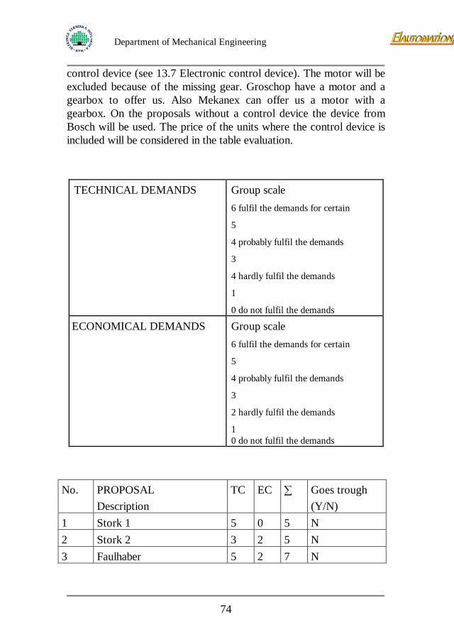
control device (see 13.7 Electronic control device). The motor will be excluded because of the missing gear. Groschop have a motor and a gearbox to offer us. Also Mekanex can offer us a motor with a gearbox. On the proposals without a control device the device from Bosch will be used. The price of the units where the control device is included will be considered in the table evaluation.
TECHNICAL DEMANDS
Group scale 6 fulfil the demands for certain
5
4 probably fulfil the demands
3
4 hardly fulfil the demands
1
0 do not fulfil the demands
ECONOMICAL DEMANDS
Group scale 6 fulfil the demands for certain 5
4 probably fulfil the demands
3
2 hardly fulfil the demands
1 0 do not fulfil the demands
No. PROPOSAL Description
TC EC ∑ Goes trough (Y/N)
1 Stork 1 5 0 5 N 2 Stork 2 3 2 5 N 3 Faulhaber 5 2 7 N
74
Department of Mechanical Engineering
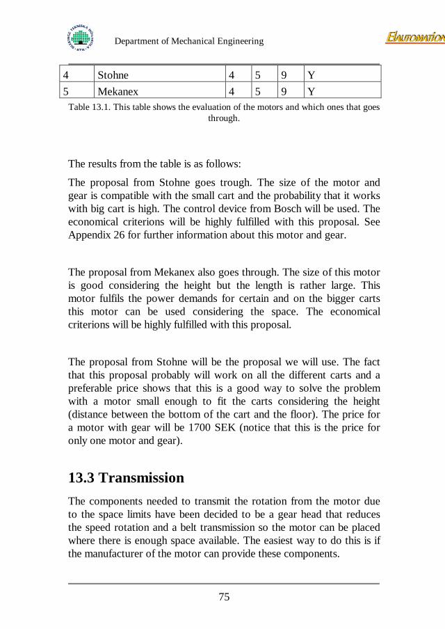
4 Stohne 4 5 9 Y 5 Mekanex 4 5 9 Y
Table 13.1. This table shows the evaluation of the motors and which ones that goes through.
The results from the table is as follows:
The proposal from Stohne goes trough. The size of the motor and gear is compatible with the small cart and the probability that it works with big cart is high. The control device from Bosch will be used. The economical criterions will be highly fulfilled with this proposal. See Appendix 26 for further information about this motor and gear.
The proposal from Mekanex also goes through. The size of this motor is good considering the height but the length is rather large. This motor fulfils the power demands for certain and on the bigger carts this motor can be used considering the space. The economical criterions will be highly fulfilled with this proposal.
The proposal from Stohne will be the proposal we will use. The fact that this proposal probably will work on all the different carts and a preferable price shows that this is a good way to solve the problem with a motor small enough to fit the carts considering the height (distance between the bottom of the cart and the floor). The price for a motor with gear will be 1700 SEK (notice that this is the price for only one motor and gear).
13.3 Transmission The components needed to transmit the rotation from the motor due to the space limits have been decided to be a gear head that reduces the speed rotation and a belt transmission so the motor can be placed where there is enough space available. The easiest way to do this is if the manufacturer of the motor can provide these components.
75
Department of Mechanical Engineering
13.3.1 Driving wheel
Three suppliers of wheels have been contacted.
Rhombus
Blickle
Tellus
Small wheels without bearings are unusual. Tellus is the only supplier that can provide the wheel needed to take the load of the cart and function as a driving wheel. These wheels are coated with polyurethane and are highly durable. The wheelbase is made of cast iron. The axle is not included and the suggestion from the supplier is that we produce it ourselves. As mentioned before the diameter is 80mm and the width is 30mm. The price for only one wheel is 180 SEK.
13.4 Electric control device In the choice of motor control we had to consider several facts that is desirable. A constrain for the control to withhold such as: voltage and provided current, speed control, overload limit, two directions of travel, soft start/stop function, and perhaps a brake function.
We did find a programmable motor control provided by Bosch, fulfilling our demands and also some of our desires. Here presented:
ROBO Tronic type 3
Programmable motor control
24V, two directions of travel
Functions:
• Programmable overload limit
• Speed control
76
Department of Mechanical Engineering
• Programmable soft start/stop
• Electrical brake function
Engine size 80mm
24V 1-25A transient more
This is a fully working control for our application, we will choose to, if the motor manufacturer can provide motor and a satisfying control, not to use the Bosch control because of the reduced number of subcontractors and the fact that there will be next to no problem at all concerning compatibility.
13.5 Battery In the choice of battery we had to consider which type of battery we could use and from which manufacturer. Because of the limited space and the needed power ”Small Sealed Batteries” caught our eyes.
These batteries are completely maintenance free, they can be placed in any position without leakage and has the best energy/weight/space factors among batteries, and they can also be recharged at any time without being discharged before.
In consultation with Global Batterier AB we decided to use a “Small Sealed Battery” which allows a higher energy output, called “High Rate Small Sealed Battery”. This battery is specially designed to guarantee higher power output during fast discharge applications; the battery is modified in order to increase the contact with the electrolyte. This increased surface, more readily permits the electrochemical reactions, which are needed to create current. See Appendix 20 for information about construction.
Our choice of manufacturer (Global Batterier AB) was based on first impression.
77
Department of Mechanical Engineering
Other companies considered were Fiamm, Power-Sonic and MK-Batteries, also providing the same type of battery, in a series production situation a quotation from each company should be done.
Please note that in case of a 24V motor we use two 12V batteries in series to provide the right voltage and in case of a 12V motor we use these batteries parallel to provide the right current. On the smallest cart there is only space to place two of these batteries, and since it’s no good idea to mix batteries with different Ah/h because of troubles with charging, the maximum battery power of the smallest cart is 12V 10Ah/20h or 24V 5Ah/20h. On the bigger carts there is a possibility to use more of these batteries and if so needed a higher voltage ex. 36V 5Ah/20h.
Chosen battery:
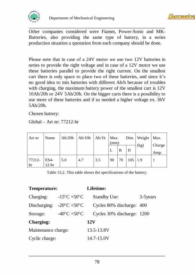
Global – Art nr: 77212-hr
Art nr Name Ah/20h Ah/10h Ah/1h Max. Dim.
(mm) Weight
(kg)
Max.
Charge
Amp. L B H
77212-hr
ES4-12-hr
5.0 4.7 3.5 90 70 105 1.9 1
Table 13.2. This table shows the specifications of the battery.
Temperature: Lifetime:
Charging: -15°C +50°C Standby Use: 3-5years
Discharging: -20°C +50°C Cycles 80% discharge: 400
Storage: -40°C +50°C Cycles 30% discharge: 1200
Charging: 12V
Maintenance charge: 13.5-13.8V
Cyclic charge: 14.7-15.0V
78
Department of Mechanical Engineering
Storage: Charge at least every 6th month.
Discharging: 12V
Lowest discharge voltage: 10.5V
Even if the charging was decided to be left out of the project we’ve put some thought into it. Since there according to SAS are no possibilities to charge the batteries onboard the charging has to be done either between flights or when the carts are stored over night at the airport. The maximum charge time will therefore be during night for approximately five to seven hours.
In consultation with battery manufacturer it was found that for these types of battery, using the maximum charge current of 1Amp it is possible to fully charge a major discharged battery in around five hours, less discharged battery equals to less charging time, though it might be to take under consideration that the last 15% of the battery capacity demands longer charge time (power/charge time) than the rest of the battery.
It is also necessary to take the way of charging under consideration, here are some possibilities for this:
One is to simply plug in each module during night to a charger.
Another is to use the type of system found in cordless drilling machines with removable batteries placed in the charger during night, or replace the batteries in the cart with fresh ones and charge the others to next night.
14 First prototype design We have built one easy prototype in order to test the chosen architecture solution. This prototype is the first step for determinate the friction of the driving wheel on the carpet. Afterwards we have modified this prototype to test this solution with an electric transmission. According to our primary calculation we have chosen to use a portative electric drill as a power supplier. This type of transmission fulfils our demand. We have tried to create the same
79
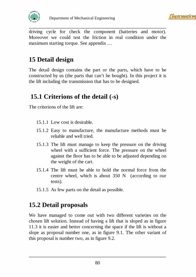
Department of Mechanical Engineering
driving cycle for check the component (batteries and motor). Moreover we could test the friction in real condition under the maximum starting torque. See appendix …
15 Detail design The detail design contains the part or the parts, which have to be constructed by us (the parts that can’t be bought). In this project it is the lift including the transmission that has to be designed.
15.1 Criterions of the detail (-s) The criterions of the lift are:
15.1.1 Low cost is desirable.
15.1.2 Easy to manufacture, the manufacture methods must be reliable and well tried.
15.1.3 The lift must manage to keep the pressure on the driving wheel with a sufficient force. The pressure on the wheel against the floor has to be able to be adjusted depending on the weight of the cart.
15.1.4 The lift must be able to hold the normal force from the centre wheel, which is about 350 N (according to our tests).
15.1.5 As few parts on the detail as possible.
15.2 Detail proposals We have managed to come out with two different varieties on the chosen lift solution. Instead of having a lift that is sloped as in figure 11.3 it is easier and better concerning the space if the lift is without a slope as proposal number one, as in figure 9.1. The other variant of this proposal is number two, as in figure 9.2.
80
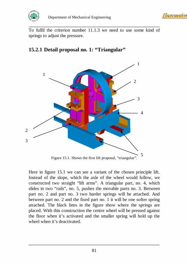
Department of Mechanical Engineering
To fulfil the criterion number 11.1.3 we need to use some kind of springs to adjust the pressure. 15.2.1 Detail proposal no. 1: “Triangular”
Figure 15.1. Shows the first lift proposal, “triangular”.
Here in figure 15.1 we can see a variant of the chosen principle lift. Instead of the slope, which the axle of the wheel would follow, we constructed two straight “lift arms”. A triangular part, no. 4, which slides in two “rails”, no. 5, pushes the movable parts no. 3. Between part no. 2 and part no. 3 two harder springs will be attached. And between part no. 2 and the fixed part no. 1 it will be one softer spring attached. The black lines in the figure show where the springs are placed. With this construction the centre wheel will be pressed against the floor when it’s activated and the smaller spring will hold up the wheel when it’s deactivated.
1
1
2
2
3
3
4
5
81
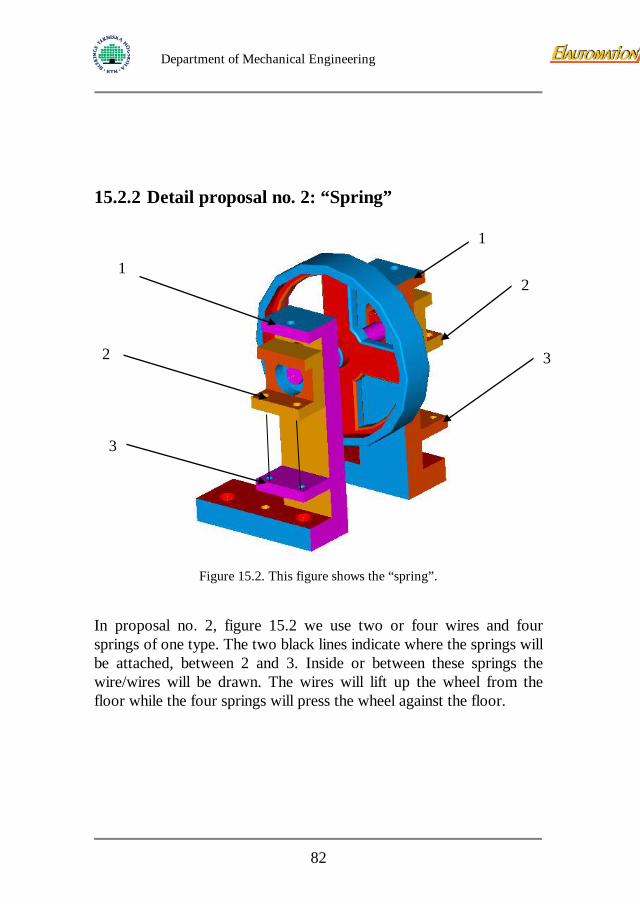
Department of Mechanical Engineering
15.2.2 Detail proposal no. 2: “Spring”
Figure 15.2. This figure shows the “spring”.
In proposal no. 2, figure 15.2 we use two or four wires and four springs of one type. The two black lines indicate where the springs will be attached, between 2 and 3. Inside or between these springs the wire/wires will be drawn. The wires will lift up the wheel from the floor while the four springs will press the wheel against the floor.
1
1
2
2
3
3
82
Department of Mechanical Engineering
15.3 Locking device solution
Figure 15.3. The solution of the locking device.
In the figure above you can see the solution, which perform the lock of the lift in the disengaged position. The lever No.1 is linked to one of the 2 pedals; the No. 2 is linked to the other. The both wires No. 3 are connected to the lifting device No.2 in figure 15.2. The both wires are linked together by the No. 4 part. This part slide inside the oblong hole bores in the part No. 5. The shaft No. 6 turned in the part No. 5 and connected to a torsion spring in order to keep a part No. 4 in place. The two hooks No. 7 lock the part No. 4.
15.4 Test to determine the needed down force To determine the force, which we need to get the right pressure against the floor, we did as following. (The force that is needed to brake the cart).
NF ⋅= µ Equation 15.1. This equation shows how to get the needed force.
1
2 3
5
4
6
7
83
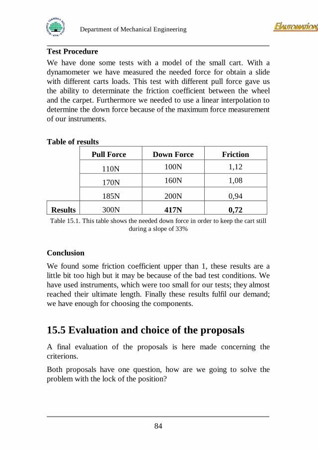
Department of Mechanical Engineering
Test Procedure We have done some tests with a model of the small cart. With a dynamometer we have measured the needed force for obtain a slide with different carts loads. This test with different pull force gave us the ability to determinate the friction coefficient between the wheel and the carpet. Furthermore we needed to use a linear interpolation to determine the down force because of the maximum force measurement of our instruments. Table of results
Pull Force Down Force Friction
110N 100N 1,12
170N 160N 1,08
185N 200N 0,94
Results 300N 417N 0,72 Table 15.1. This table shows the needed down force in order to keep the cart still
during a slope of 33%
Conclusion
We found some friction coefficient upper than 1, these results are a little bit too high but it may be because of the bad test conditions. We have used instruments, which were too small for our tests; they almost reached their ultimate length. Finally these results fulfil our demand; we have enough for choosing the components.
15.5 Evaluation and choice of the proposals A final evaluation of the proposals is here made concerning the criterions.
Both proposals have one question, how are we going to solve the problem with the lock of the position?
84
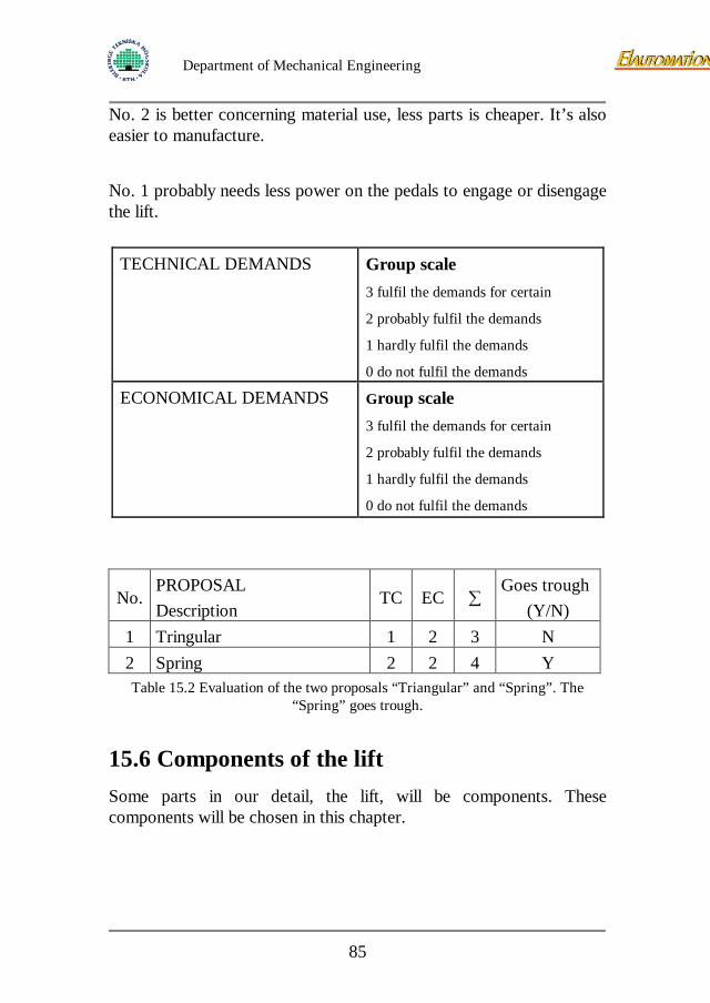
Department of Mechanical Engineering
No. 2 is better concerning material use, less parts is cheaper. It’s also easier to manufacture.
No. 1 probably needs less power on the pedals to engage or disengage the lift.
TECHNICAL DEMANDS
Group scale
3 fulfil the demands for certain
2 probably fulfil the demands
1 hardly fulfil the demands
0 do not fulfil the demands
ECONOMICAL DEMANDS
Group scale
3 fulfil the demands for certain
2 probably fulfil the demands
1 hardly fulfil the demands
0 do not fulfil the demands
No. PROPOSAL Description
TC EC ∑ Goes trough
(Y/N) 1 Tringular 1 2 3 N 2 Spring 2 2 4 Y Table 15.2 Evaluation of the two proposals “Triangular” and “Spring”. The
“Spring” goes trough.
15.6 Components of the lift Some parts in our detail, the lift, will be components. These components will be chosen in this chapter.
85
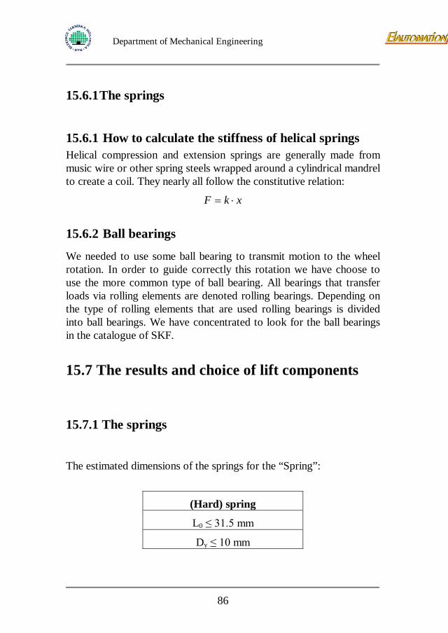
Department of Mechanical Engineering
15.6.1 The springs
15.6.1 How to calculate the stiffness of helical springs Helical compression and extension springs are generally made from music wire or other spring steels wrapped around a cylindrical mandrel to create a coil. They nearly all follow the constitutive relation:
xkF ⋅= 15.6.2 Ball bearings
We needed to use some ball bearing to transmit motion to the wheel rotation. In order to guide correctly this rotation we have choose to use the more common type of ball bearing. All bearings that transfer loads via rolling elements are denoted rolling bearings. Depending on the type of rolling elements that are used rolling bearings is divided into ball bearings. We have concentrated to look for the ball bearings in the catalogue of SKF.
15.7 The results and choice of lift components 15.7.1 The springs
The estimated dimensions of the springs for the “Spring”:
(Hard) spring
L0 ≤ 31.5 mm
Dy ≤ 10 mm
86
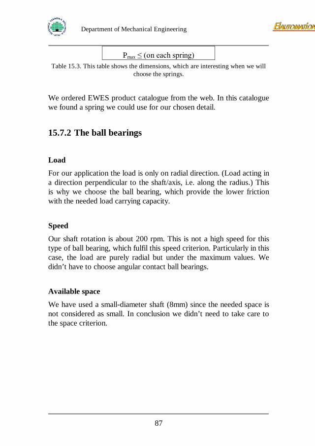
Department of Mechanical Engineering
Pmax ≤ (on each spring)
Table 15.3. This table shows the dimensions, which are interesting when we will choose the springs.
We ordered EWES product catalogue from the web. In this catalogue we found a spring we could use for our chosen detail.
15.7.2 The ball bearings
Load
For our application the load is only on radial direction. (Load acting in a direction perpendicular to the shaft/axis, i.e. along the radius.) This is why we choose the ball bearing, which provide the lower friction with the needed load carrying capacity.
Speed
Our shaft rotation is about 200 rpm. This is not a high speed for this type of ball bearing, which fulfil this speed criterion. Particularly in this case, the load are purely radial but under the maximum values. We didn’t have to choose angular contact ball bearings.
Available space
We have used a small-diameter shaft (8mm) since the needed space is not considered as small. In conclusion we didn’t need to take care to the space criterion.
87
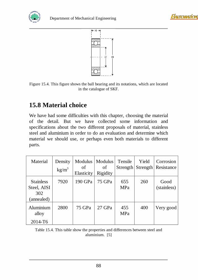
Department of Mechanical Engineering
Figure 15.4. This figure shows the ball bearing and its notations, which are located
in the catalogue of SKF.
15.8 Material choice We have had some difficulties with this chapter, choosing the material of the detail. But we have collected some information and specifications about the two different proposals of material, stainless steel and aluminium in order to do an evaluation and determine which material we should use, or perhaps even both materials to different parts.
Material Density
kg/m3
Modulus of
Elasticity
Modulus of
Rigidity
Tensile Strength
Yield Strength
Corrosion Resistance
Stainless Steel, AISI
302 (annealed)
7920 190 GPa 75 GPa 655 MPa
260 Good (stainless)
Aluminium alloy
2014-T6
2800 75 GPa 27 GPa 455 MPa
400 Very good
Table 15.4. This table show the properties and differences between steel and aluminium. [5]
88
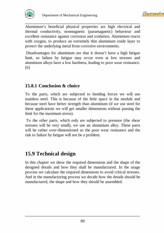
Department of Mechanical Engineering
Aluminium’s beneficial physical properties are high electrical and thermal conductivity, nonmagnetic (paramagnetic) behaviour and excellent resistance against corrosion and oxidation. Aluminium reacts with oxygen, to produce an extremely thin aluminium oxide layer to protect the underlying metal from corrosive environments.
Disadvantages for aluminium are that it doesn’t have a high fatigue limit, so failure by fatigue may occur even at low stresses and aluminium alloys have a low hardness, leading to poor wear resistance. [6] 15.8.1 Conclusion & choice
To the parts, which are subjected to bending forces we will use stainless steel. This is because of the little space in the module and because steel have better strength than aluminium (if we use steel for these applications we will get smaller dimensions without passing the limit for the maximum stress).
To the other parts, which only are subjected to pressure (the shear stresses will be very small), we use an aluminium alloy. These parts will be rather over-dimensioned so the poor wear resistance and the risk to failure by fatigue will not be a problem.
15.9 Technical design In this chapter we show the required dimensions and the shape of the designed details and how they shall be manufactured. In the usage process we calculate the required dimensions to avoid critical stresses. And in the manufacturing process we decide how the details should be manufactured, the shape and how they should be assembled.
89
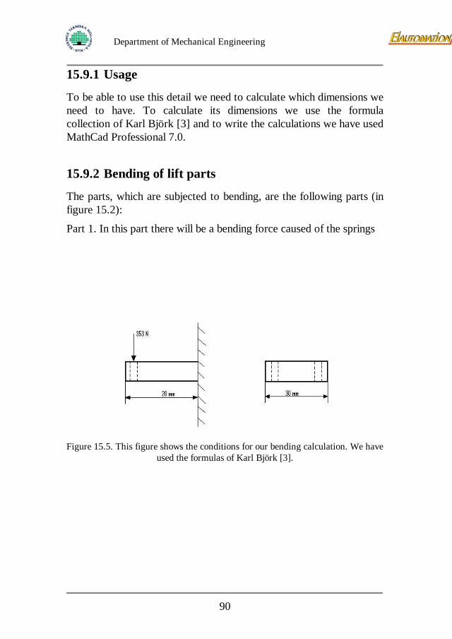
Department of Mechanical Engineering
15.9.1 Usage
To be able to use this detail we need to calculate which dimensions we need to have. To calculate its dimensions we use the formula collection of Karl Björk [3] and to write the calculations we have used MathCad Professional 7.0.
15.9.2 Bending of lift parts
The parts, which are subjected to bending, are the following parts (in figure 15.2):
Part 1. In this part there will be a bending force caused of the springs
Figure 15.5. This figure shows the conditions for our bending calculation. We have
used the formulas of Karl Björk [3].
90
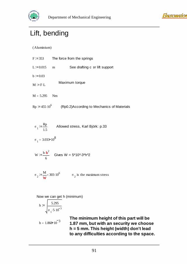
Department of Mechanical Engineering
Lift, bending
Aluminium( )
F 353 The force from the springs
L 0.015 m See drafting over lift support
b 0.03
Maximum torqueM F L.
M 5.295= Nm
Rp 455 106. (Rp0.2)According to Mechanics of Materials
σ 1Rp1.5
Allowed stress, Karl Björk: p.33
σ 1 3.033 108=
W b h2.
6h Gives W = 5*10 -̂3*h 2̂
σ 2MW
303 106.<W
σ 2 is the maximum stress
Now we can get h (minimum)
h 5.295
σ 1 5. 10 3.
The minimum height of this part will be1.87 mm, but with an security we chooseh = 5 mm. This height (width) don't lead to any difficulties according to the space.
h 1.868 10 3=
91
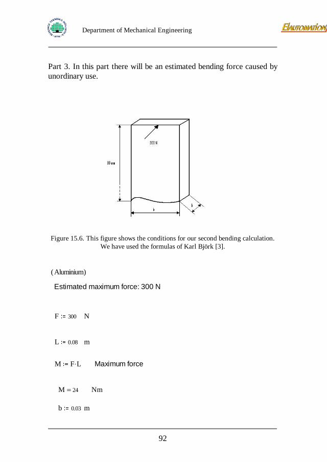
Department of Mechanical Engineering
Part 3. In this part there will be an estimated bending force caused by unordinary use.
Figure 15.6. This figure shows the conditions for our second bending calculation.
We have used the formulas of Karl Björk [3].
Aluminium( )
Estimated maximum force: 300 N
F 300 N
L 0.08 m
M F L. Maximum force
M 24= Nm
b 0.03 m
92
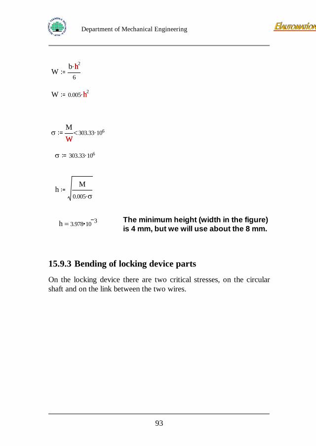
Department of Mechanical Engineering
Wb h2.
6
h
W 0.005 h2.h
σMW
303.33 106.<W
σ 303.33 106.
hM
0.005 σ.
The minimum height (width in the figure) is 4 mm, but we will use about the 8 mm. h 3.978 10 3=
15.9.3 Bending of locking device parts
On the locking device there are two critical stresses, on the circular shaft and on the link between the two wires.
93
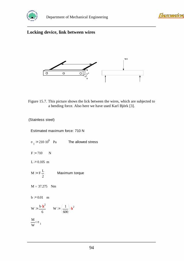
Department of Mechanical Engineering
Locking device, link between wires
Figure 15.7. This picture shows the lick between the wires, which are subjected to
a bending force. Also here we have used Karl Björk [3].
(Stainless steel)
Estimated maximum force: 710 N
σ 1 210 106. Pa The allowed stress
F 710 N
L 0.105 m
M F L2. Maximum torque
M 37.275= Nm
b 0.01 m
W b h2.
6h W 1
600h2.h
MW
σ 1<
94
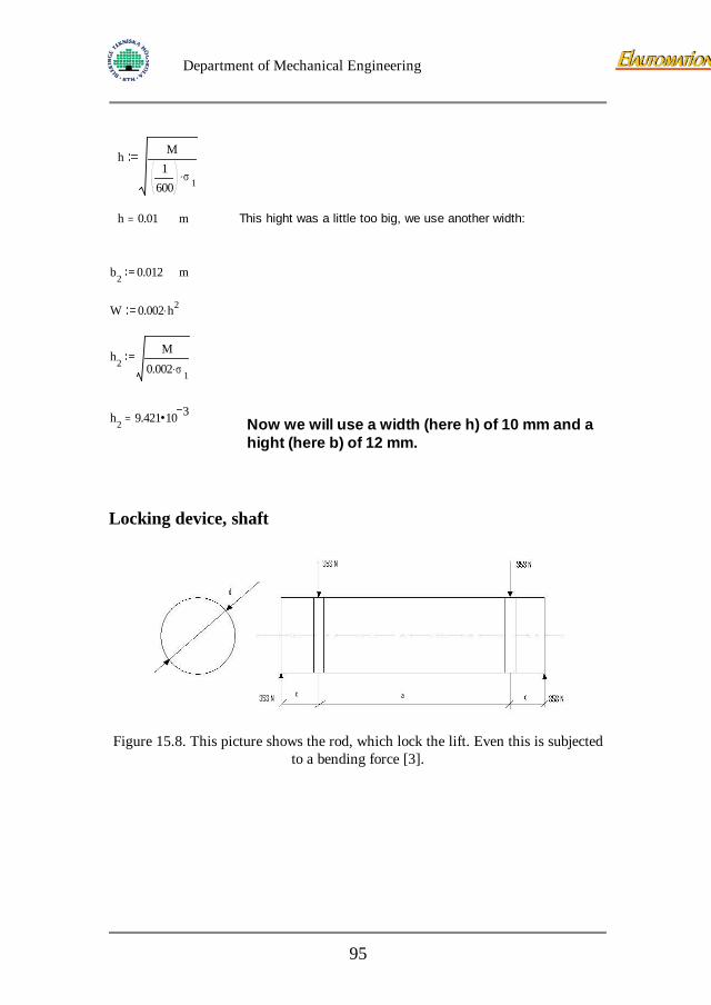
Department of Mechanical Engineering
h M1
600σ 1.
h 0.01= m This hight was a little too big, we use another width:
b2 0.012 m
W 0.002 h2.
h2M
0.002 σ 1.
h2 9.421 10 3= Now we will use a width (here h) of 10 mm and a hight (here b) of 12 mm.
Locking device, shaft
Figure 15.8. This picture shows the rod, which lock the lift. Even this is subjected
to a bending force [3].
95
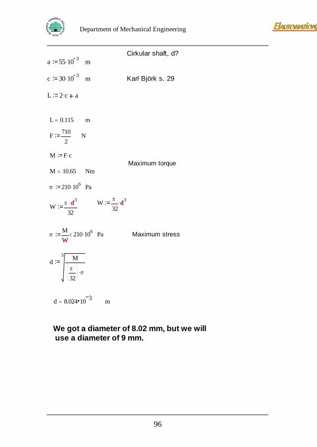
Department of Mechanical Engineering
Cirkular shaft, d?
a 55 10 3. m
c 30 10 3. m Karl Björk s. 29
L 2 c. a L 0.115= m
F 7102
N
M F c.Maximum torque
M 10.65= Nm
σ 210 106. Pa
W π
32d3.dW π d3.
32d
σMW
210 106.<W
Pa Maximum stress
d3 M
π
32σ.
d 8.024 10 3= m
We got a diameter of 8.02 mm, but we will use a diameter of 9 mm.
96
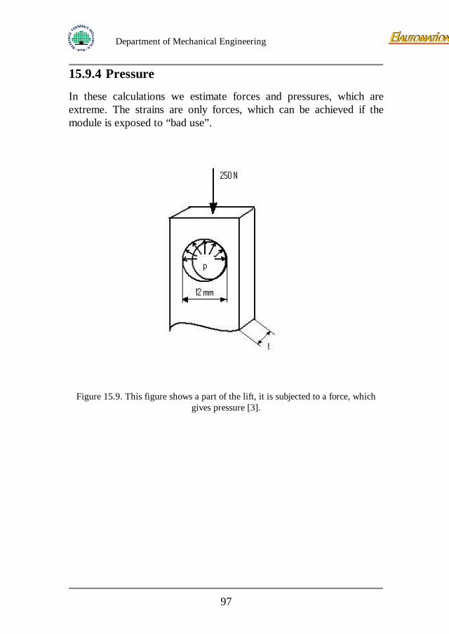
Department of Mechanical Engineering
15.9.4 Pressure
In these calculations we estimate forces and pressures, which are extreme. The strains are only forces, which can be achieved if the module is exposed to “bad use”.
Figure 15.9. This figure shows a part of the lift, it is subjected to a force, which
gives pressure [3].
97
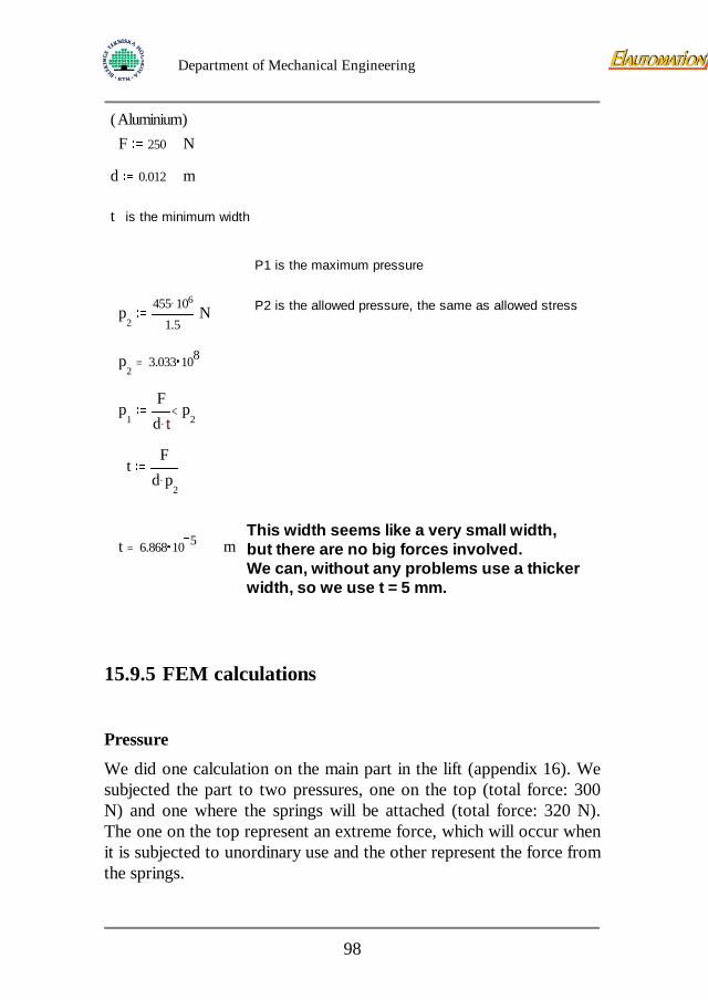
Department of Mechanical Engineering
Aluminium( )F 250 N
d 0.012 m
t is the minimum width
P1 is the maximum pressure
P2 is the allowed pressure, the same as allowed stressp2
455 106.
1.5N
p2
3.033 108=
p1
Fd t.
p2
<t
tF
d p2
.
This width seems like a very small width, but there are no big forces involved. We can, without any problems use a thicker width, so we use t = 5 mm.
t 6.868 10 5= m
15.9.5 FEM calculations
Pressure
We did one calculation on the main part in the lift (appendix 16). We subjected the part to two pressures, one on the top (total force: 300 N) and one where the springs will be attached (total force: 320 N). The one on the top represent an extreme force, which will occur when it is subjected to unordinary use and the other represent the force from the springs.
98
Department of Mechanical Engineering
The results of this FEM calculation:
• A maximum stress: 1.46*104 N/mm2
• A maximum displacement: 4.19*10-2 mm
After this FEM we can tell that our chosen dimensions are more than enough, critical stresses will not be achieved (we can use the chosen dimensions from the calculations made by hand).
Locking device
On the locking device there are two different FEM calculations, we have done calculations by hand on both. Locking device I is the first FEM calculation (appendix 17) and locking device II is the second FEM calculation (appendix 18). The results are as below.
Locking device I:
• Maximum stress: 1.69*10^2 N/mm2
• Maximum displacement: 5.02*10^-2 mm
Locking device II:
• Maximum stress: 3.64*10^2 N/mm2
• Maximum displacement: 5.13*10^-2 mm.
Even here we can see that the dimensions we have chosen are enough, no critical stresses occur.
Pedal
Because of the changes for the usage of the pedals there will be higher pressure on them. We have done a FEM calculation to assure that the pedals manage to take the pressure. No critical stresses occur, see appendix 19.
99
Department of Mechanical Engineering
16 Project management
16.1 Evolution of the project phase 1 and 2 The time planning for the principal part of this project has not been precise enough. Therefore an evaluation of this part considering time is quiet hard to do. All I can say is that we were at least not in late. The phase was finished in time with satisfying results.
The time planning for the primary part of the project has been more detailed. In the beginning two team members dropped off because of illness and an exam. The project proceeded smoothly anyway because the planning was rather rough. The making of a prototype was finished more rapidly than expected. When we started to work on the choosing component part and detail construction things went well in the beginning. Problems to find a motor that was good for application delayed both the choosing component task and the detail construction. Up to 30 motor manufacturers were contacted about a suitable motor and as it is today we have only two motors that may work and with one of the suppliers we have communication problems. These external constrains can give one day or more without sufficient work. Nor components depending on the layout of the motor can be chosen. When a good motor is found the project can advance again with full speed.
16.2 Risks As mentioned before the primary phase started with some team members who weren’t able to work. Calculated risks in this project were:
Exams
New software for a team member
External constrains, time for answering e-mail, questionnaire etc.
100
Department of Mechanical Engineering
New risks that came up during the project that weren’t calculated for:
Illness
New (but similar) software and new computers
Motivation in project team
Illness doesn’t come very unexpected but it is hard to calculate for this in the time schedule.
The switch to PC’s instead of Silicon Graphics machine was not expected and some problems with the files were encountered. This switch took almost 6 days of valuable time from the project.
Because of the problems to find a motor the whole team were put on the task to find a motor. When trying hard without succeeding the motivation in the team was decreased. Not until a motor was found the motivation and thereby the advancement of the project was secured.
In the principal phase the motivation fell due to disagreement about what to be done but it was quickly restored.
16.3 Gantt schedule The principal time schedule starts at 020121 and ends at 020308. The primary time schedule starts at 020311 and ends at 020422. By this time our exchange student have left for France. The total period for this project has then been 13 weeks. Because of exams and other constrains this is not 13 full time weeks. The accordance of the Gantt in all steps has not been totally accurate but in its entirety it has been a good plan to follow. For example the choosing components part has taken much more time while the part before has taken less time.
16.4 Meetings Meetings with Mats Walter, Morgan Klang and Christer Georgsson have taken place. An introducing meeting with Jonas Persson and
101

Department of Mechanical Engineering
Knut Blom has also taken place. This meeting gave us an introduction to the problem and a feeling of what has to be done.
The meeting with Mats Walter was a “half-time” meeting to ensure the advancement of the project.
Christer Georgsson arranged a meeting to discuss the specification of criterions and some ideas he had about the module.
Morgan Klang went through the specification of criterions and gave us his opinion about the specification.
We have also had meetings every Monday morning discussing last week and what to be done the coming week.
102
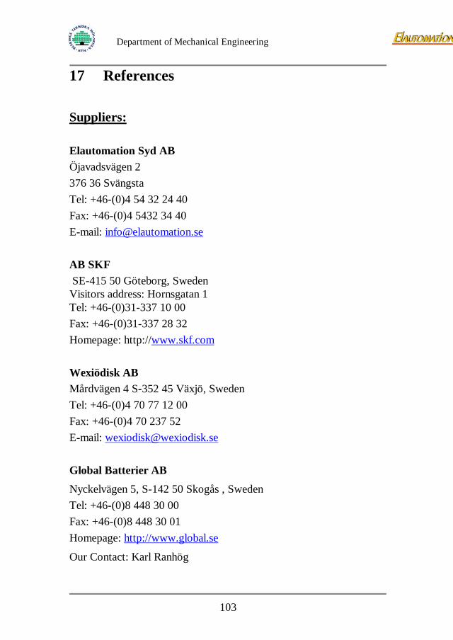
Department of Mechanical Engineering
17 References Suppliers: Elautomation Syd AB Öjavadsvägen 2 376 36 Svängsta Tel: +46-(0)4 54 32 24 40 Fax: +46-(0)4 5432 34 40 E-mail: [email protected] AB SKF SE-415 50 Göteborg, Sweden Visitors address: Hornsgatan 1 Tel: +46-(0)31-337 10 00 Fax: +46-(0)31-337 28 32 Homepage: http://www.skf.com Wexiödisk AB Mårdvägen 4 S-352 45 Växjö, Sweden Tel: +46-(0)4 70 77 12 00 Fax: +46-(0)4 70 237 52 E-mail: [email protected] Global Batterier AB
Nyckelvägen 5, S-142 50 Skogås , Sweden Tel: +46-(0)8 448 30 00 Fax: +46-(0)8 448 30 01 Homepage: http://www.global.se
Our Contact: Karl Ranhög
103

Department of Mechanical Engineering
AB DJ STORK
Box 1037
172 21 Sundbyberg
Homepage: http://www.djstork.se
Our contact: Lars Svensson STOHNE ELTEKNIK Tel: +46-(0)19 30 77 08 Our contact: Bengt Jakobsson
Literature references 1. Fredy Olsson, 1995, ”Principkonstruktion”, Lund: Lunds
Tekniska Högskola, institutionen för Maskinkonstruktion.
2. Fredy Olsson, 1995, ”Primärkonstruktion”, Lund: Lunds Tekniska Högskola, institutionen för Maskinkonstruktion.
3. Karl Björk, 3rd edition, ”Formler och Tabeller för Teknologi och Konstruktion m”.
4. Ove Erlandsson, Stefan Lagerkrans, Reinhold Näslund, Esa Vuorinen, 1990, ”Maskin handboken”, Luleå, Studentlitteratur.
5. Ferdinand P. Beer & E. Russell Johnston, JR, 1992, “Mechanics of Materials” second edition.
6. Donald R. Askeland, 1996, “The Science and Engineering of Materials” third edition. Reprinted 1998.
7. http://www.ewes.se (springs)
8. http://www.sdp-si.com (general mechanical supplier)
9. http://www.npcrobotics.com (supplier of motor, Norm Domholt)
104

Department of Mechanical Engineering
18 Appendix
Appendix
105
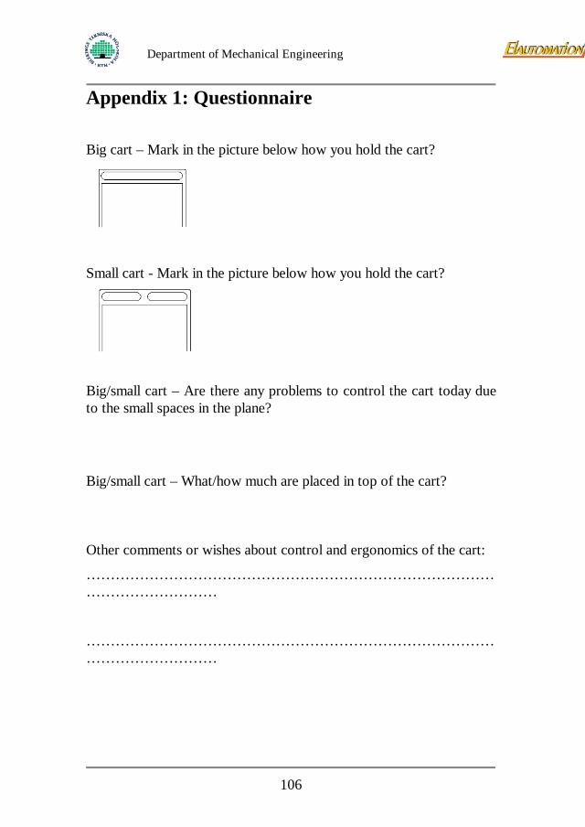
Department of Mechanical Engineering
Appendix 1: Questionnaire Big cart – Mark in the picture below how you hold the cart?
Small cart - Mark in the picture below how you hold the cart?
Big/small cart – Are there any problems to control the cart today due to the small spaces in the plane?
Big/small cart – What/how much are placed in top of the cart? Other comments or wishes about control and ergonomics of the cart:
…………………………………………………………………………………………………
…………………………………………………………………………………………………
106
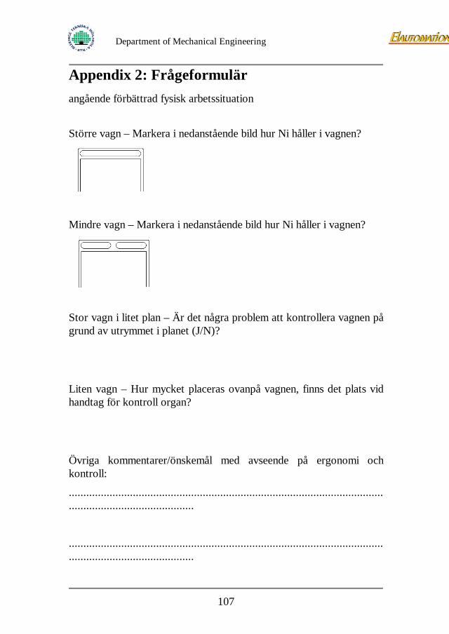
Department of Mechanical Engineering
Appendix 2: Frågeformulär angående förbättrad fysisk arbetssituation
Större vagn – Markera i nedanstående bild hur Ni håller i vagnen?
Mindre vagn – Markera i nedanstående bild hur Ni håller i vagnen?
Stor vagn i litet plan – Är det några problem att kontrollera vagnen på grund av utrymmet i planet (J/N)?
Liten vagn – Hur mycket placeras ovanpå vagnen, finns det plats vid handtag för kontroll organ?
Övriga kommentarer/önskemål med avseende på ergonomi och kontroll:
............................................................................................................
...........................................
............................................................................................................
...........................................
107
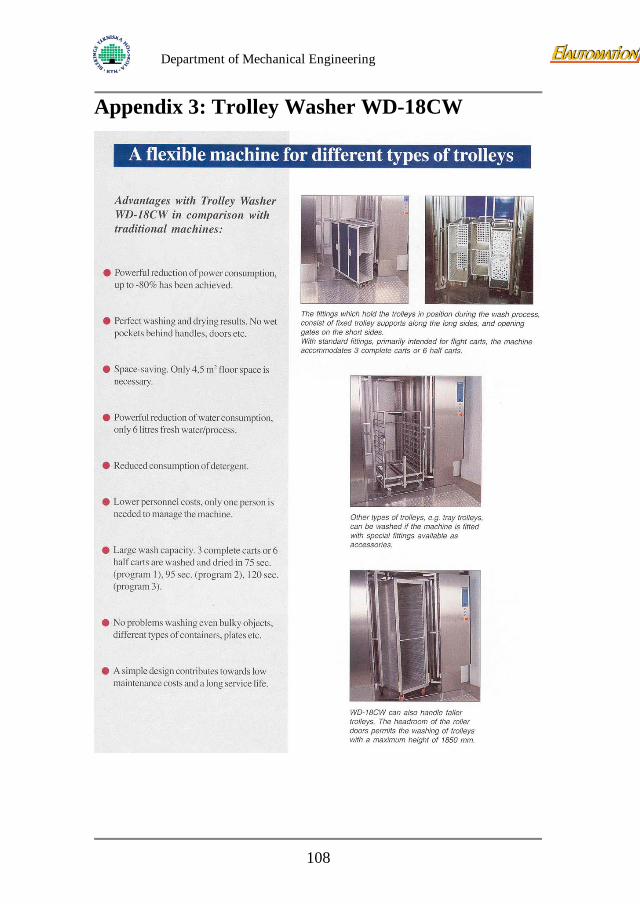
Department of Mechanical Engineering
Appendix 3: Trolley Washer WD-18CW
108
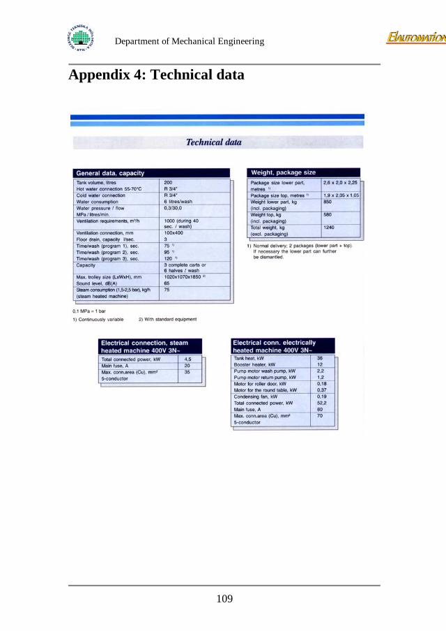
Department of Mechanical Engineering
Appendix 4: Technical data
109
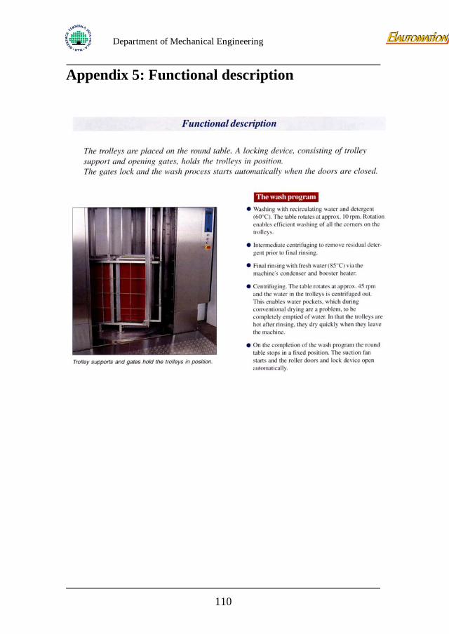
Department of Mechanical Engineering
Appendix 5: Functional description
110
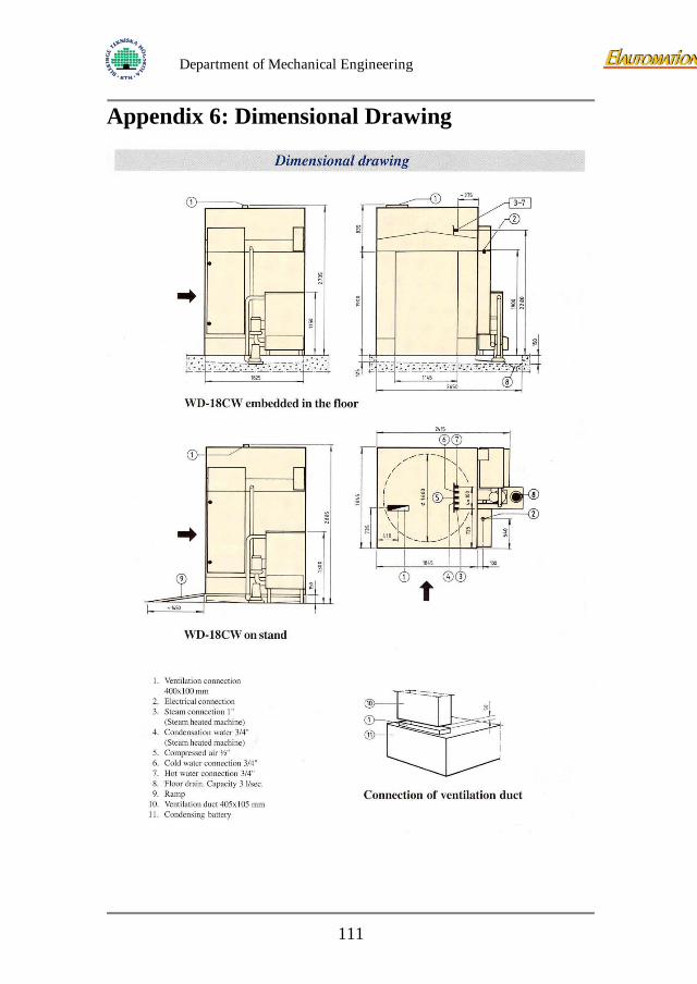
Department of Mechanical Engineering
Appendix 6: Dimensional Drawing
111
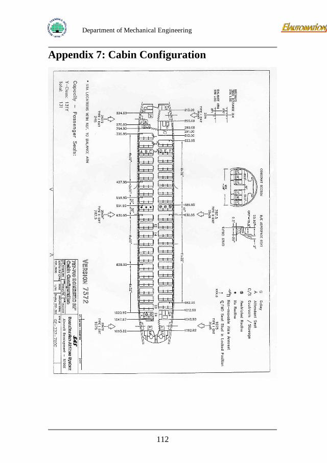
Department of Mechanical Engineering
Appendix 7: Cabin Configuration
112
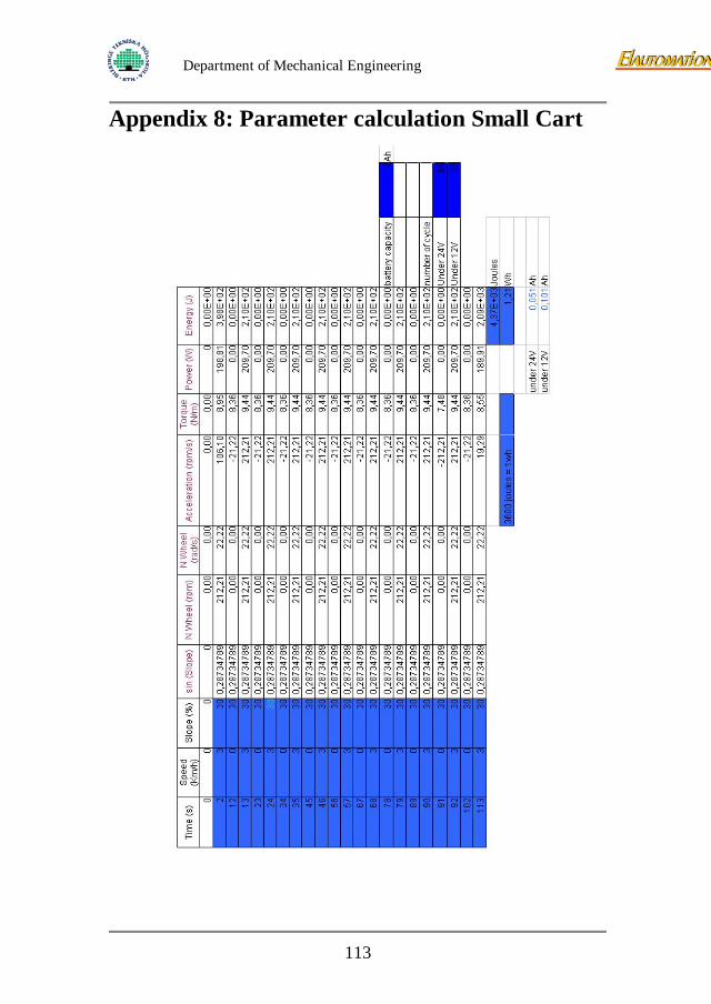
Department of Mechanical Engineering
Appendix 8: Parameter calculation Small Cart
113
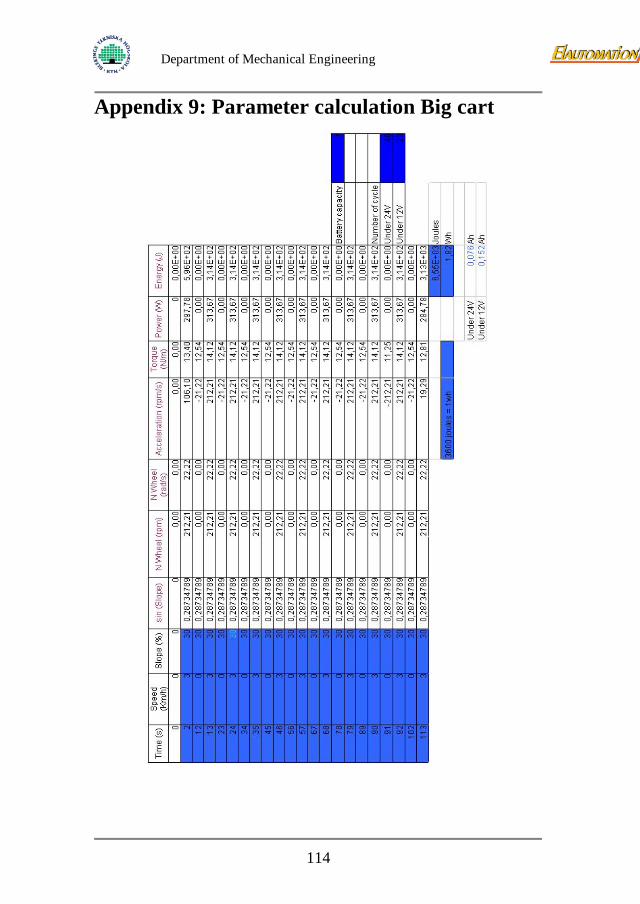
Department of Mechanical Engineering
Appendix 9: Parameter calculation Big cart
114
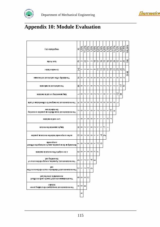
Department of Mechanical Engineering
Appendix 10: Module Evaluation
115
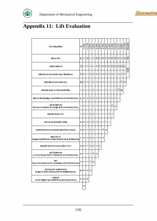
Department of Mechanical Engineering
Appendix 11: Lift Evaluation
116
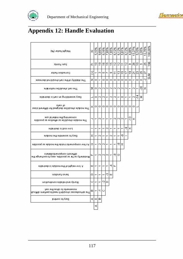
Department of Mechanical Engineering
Appendix 12: Handle Evaluation
117
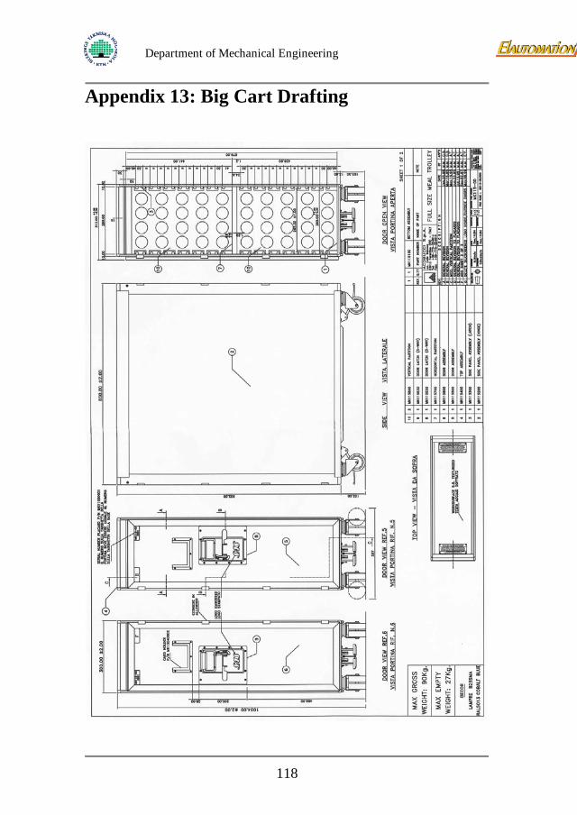
Department of Mechanical Engineering
Appendix 13: Big Cart Drafting
118
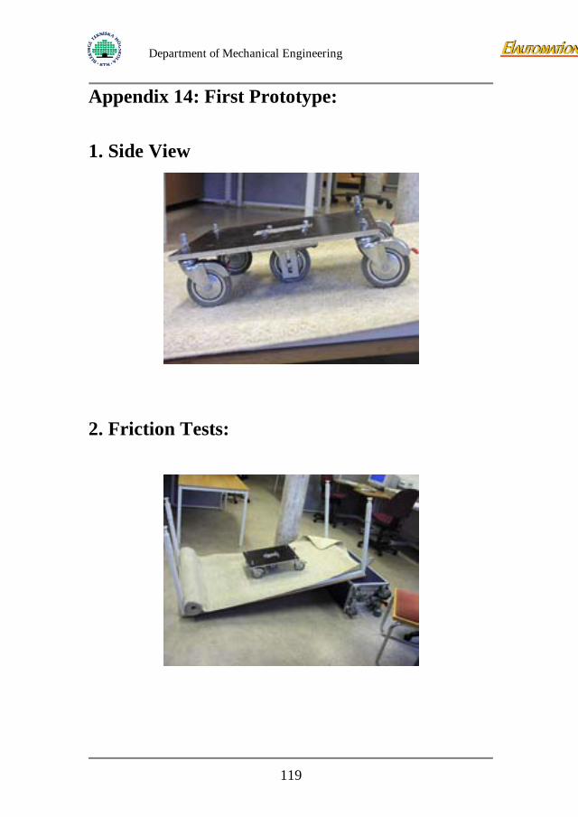
Department of Mechanical Engineering
Appendix 14: First Prototype:
1. Side View
2. Friction Tests:
119
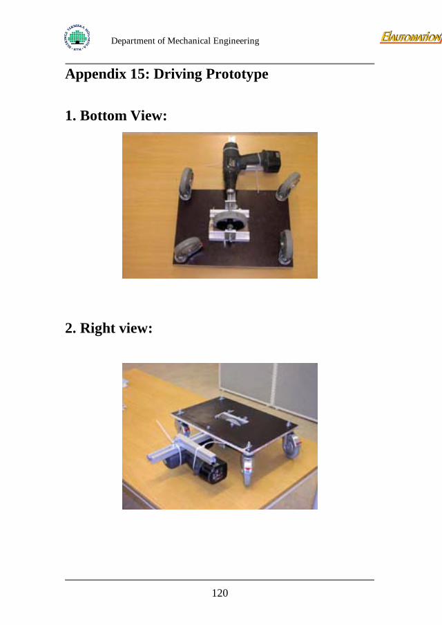
Department of Mechanical Engineering
Appendix 15: Driving Prototype
1. Bottom View:
2. Right view:
120
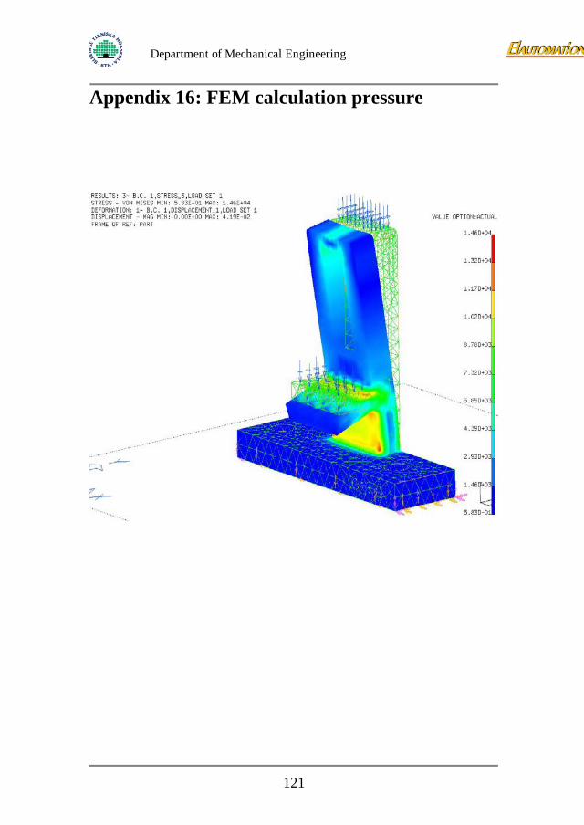
Department of Mechanical Engineering
Appendix 16: FEM calculation pressure
121
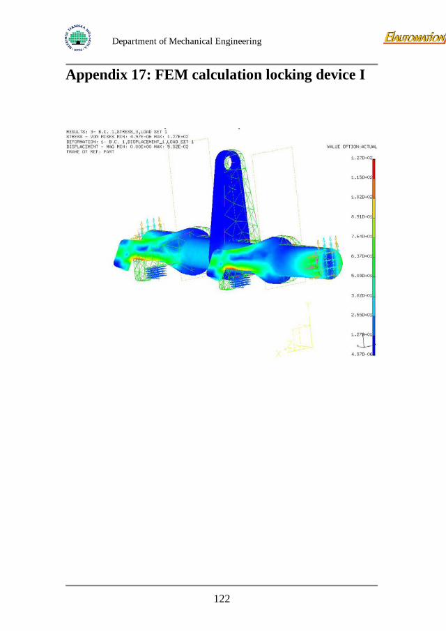
Department of Mechanical Engineering
Appendix 17: FEM calculation locking device I
122
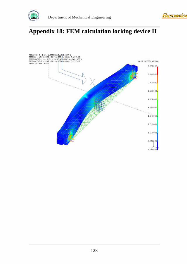
Department of Mechanical Engineering
Appendix 18: FEM calculation locking device II
123
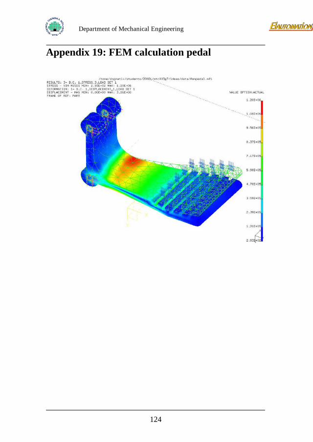
Department of Mechanical Engineering
Appendix 19: FEM calculation pedal
124
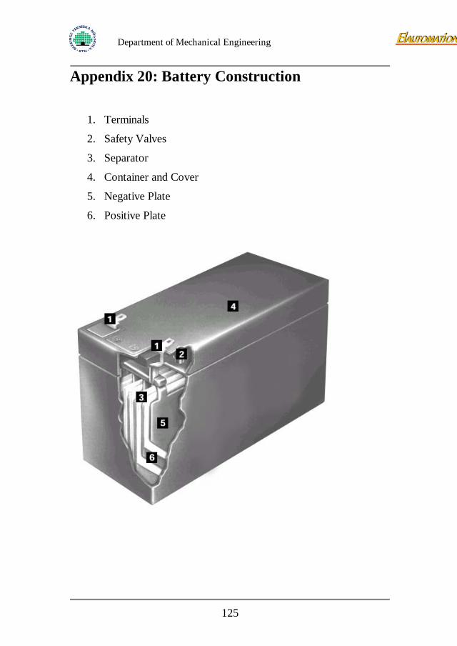
Department of Mechanical Engineering
Appendix 20: Battery Construction
1. Terminals
2. Safety Valves
3. Separator
4. Container and Cover
5. Negative Plate
6. Positive Plate
125
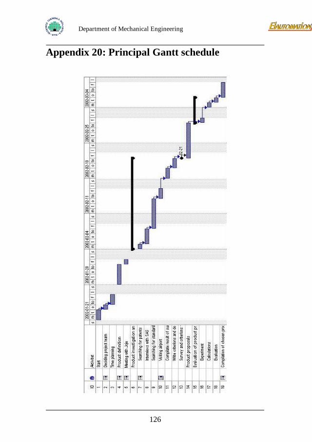
Department of Mechanical Engineering
Appendix 20: Principal Gantt schedule
126
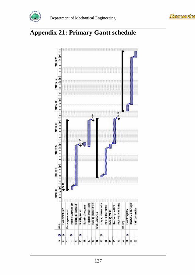
Department of Mechanical Engineering
Appendix 21: Primary Gantt schedule
127
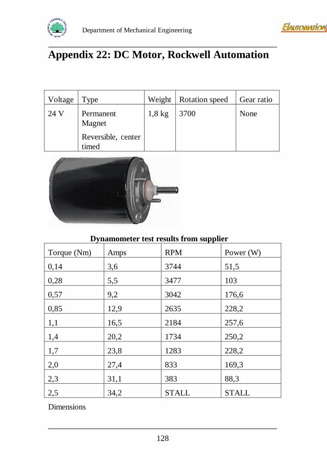
Department of Mechanical Engineering
Appendix 22: DC Motor, Rockwell Automation
Voltage Type Weight Rotation speed Gear ratio
24 V Permanent Magnet
Reversible, center timed
1,8 kg 3700 None
Dynamometer test results from supplier
Torque (Nm) Amps RPM Power (W)
0,14 3,6 3744 51,5
0,28 5,5 3477 103
0,57 9,2 3042 176,6
0,85 12,9 2635 228,2
1,1 16,5 2184 257,6
1,4 20,2 1734 250,2
1,7 23,8 1283 228,2
2,0 27,4 833 169,3
2,3 31,1 383 88,3
2,5 34,2 STALL STALL
Dimensions
128
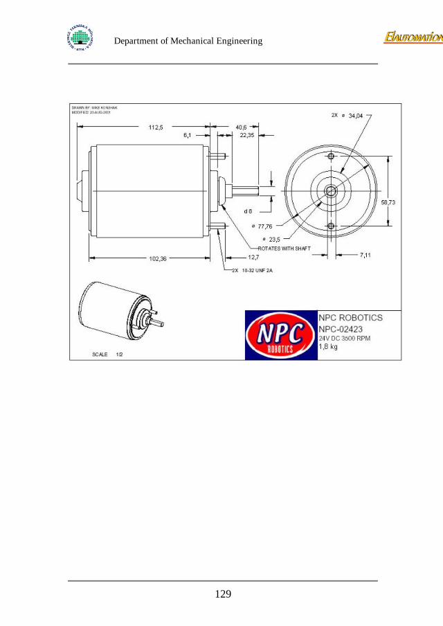
Department of Mechanical Engineering
129
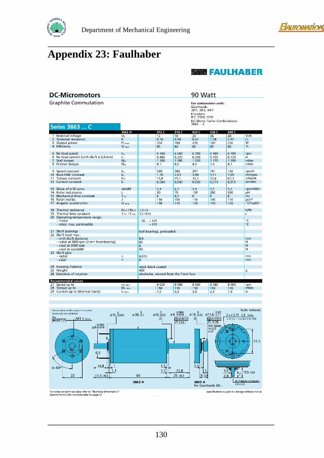
Department of Mechanical Engineering
Appendix 23: Faulhaber
130
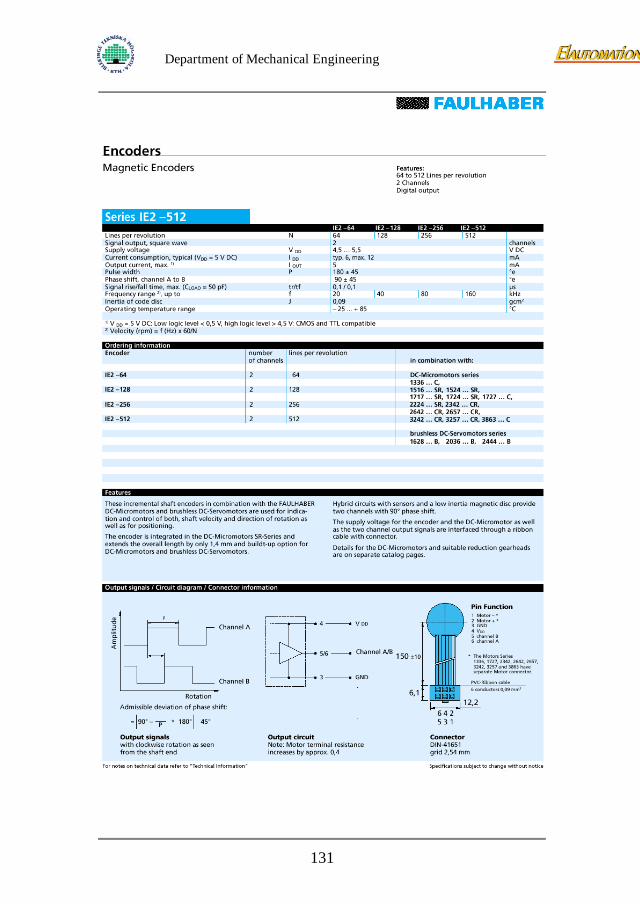
Department of Mechanical Engineering
131
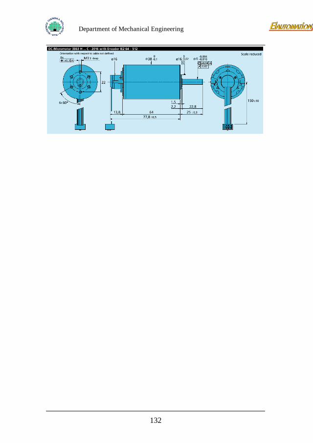
Department of Mechanical Engineering
132

Department of Mechanical Engineering
133
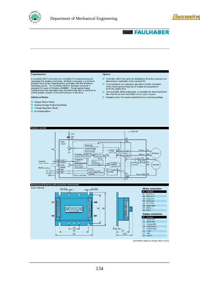
Department of Mechanical Engineering
134
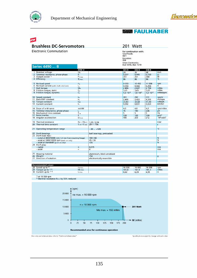
Department of Mechanical Engineering
135
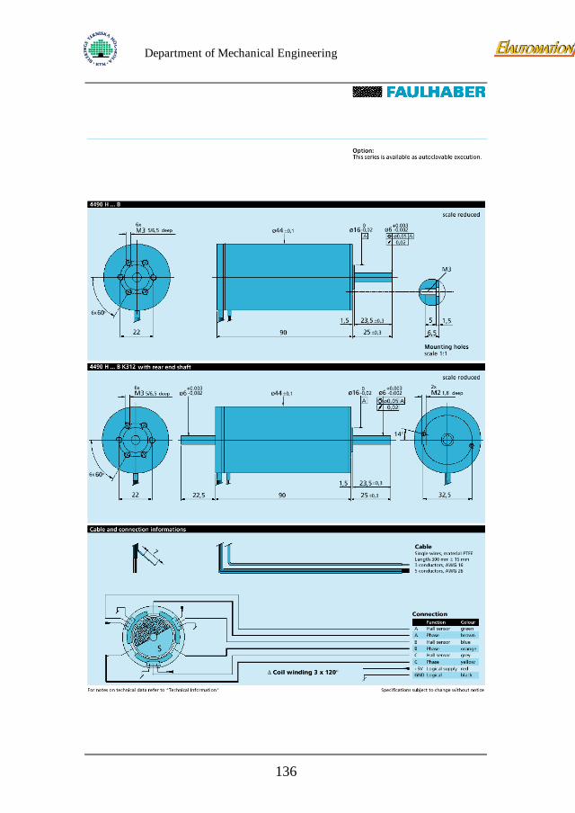
Department of Mechanical Engineering
136
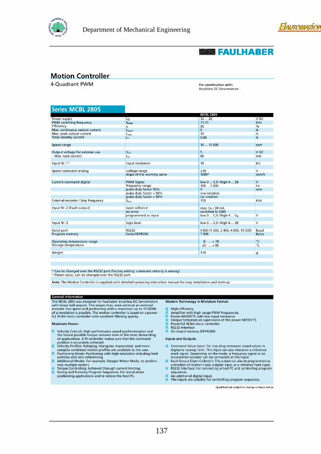
Department of Mechanical Engineering
137
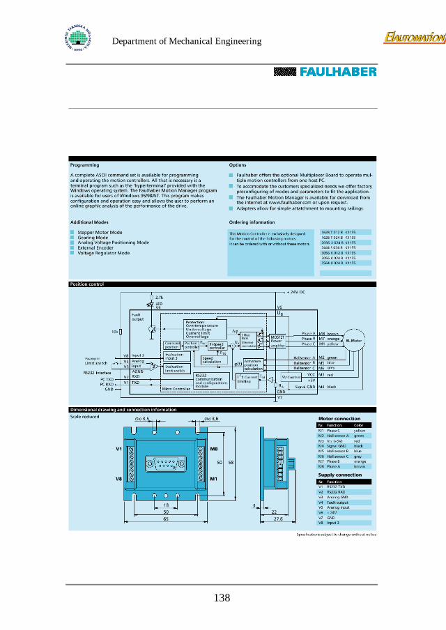
Department of Mechanical Engineering
138
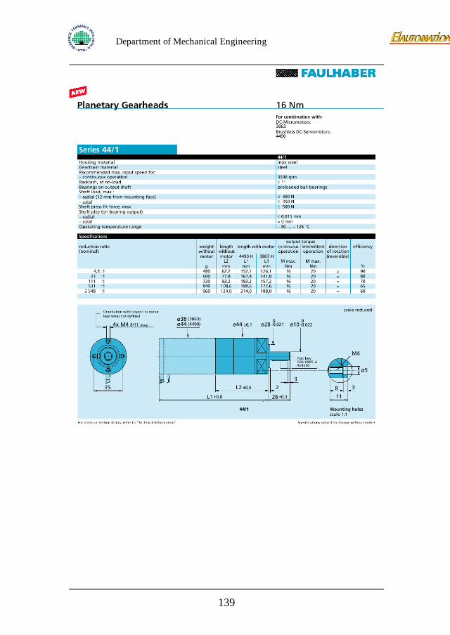
Department of Mechanical Engineering
139
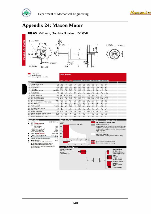
Department of Mechanical Engineering
Appendix 24: Maxon Motor
140
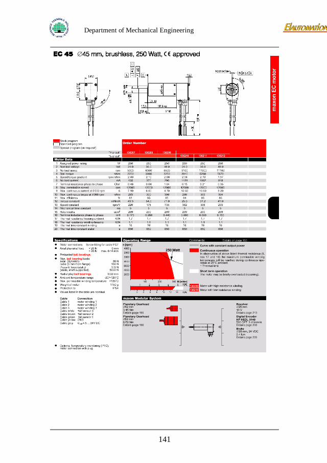
Department of Mechanical Engineering
141
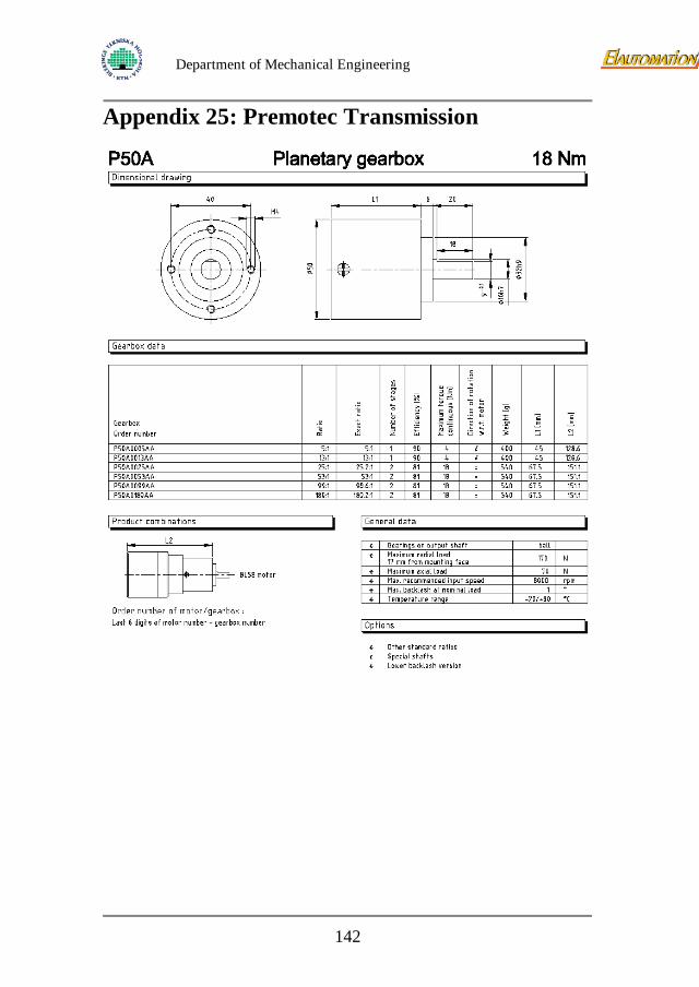
Department of Mechanical Engineering
Appendix 25: Premotec Transmission
142
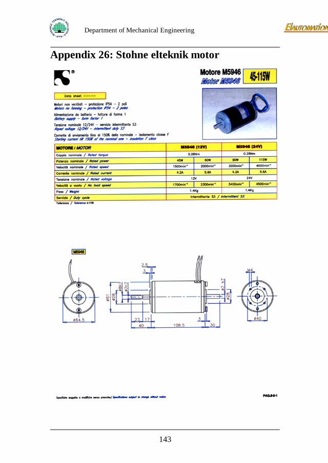
Department of Mechanical Engineering
Appendix 26: Stohne elteknik motor
143
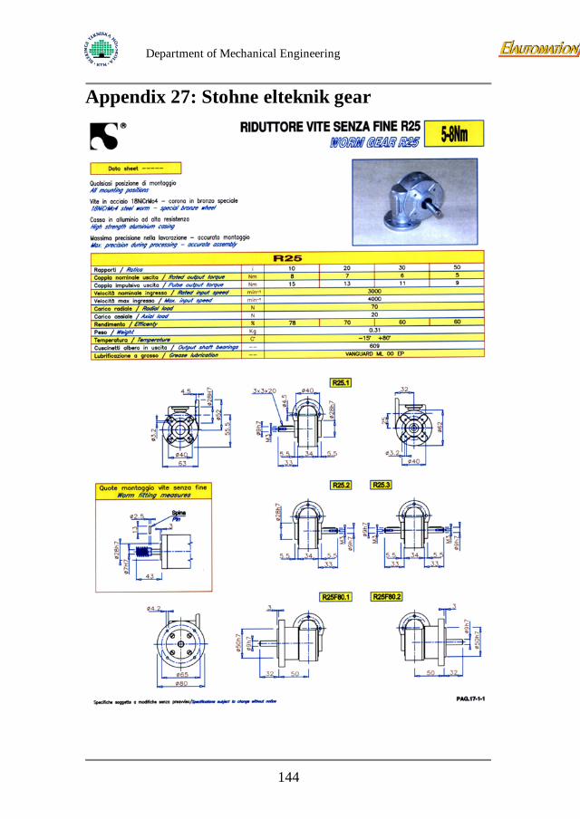
Department of Mechanical Engineering
Appendix 27: Stohne elteknik gear
144
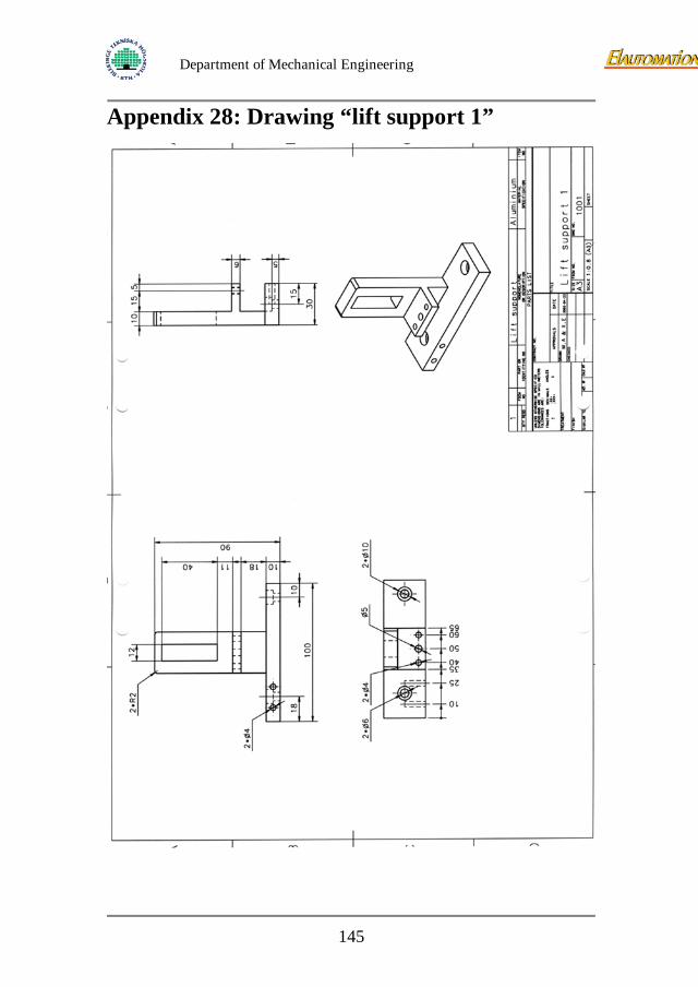
Department of Mechanical Engineering
Appendix 28: Drawing “lift support 1”
145
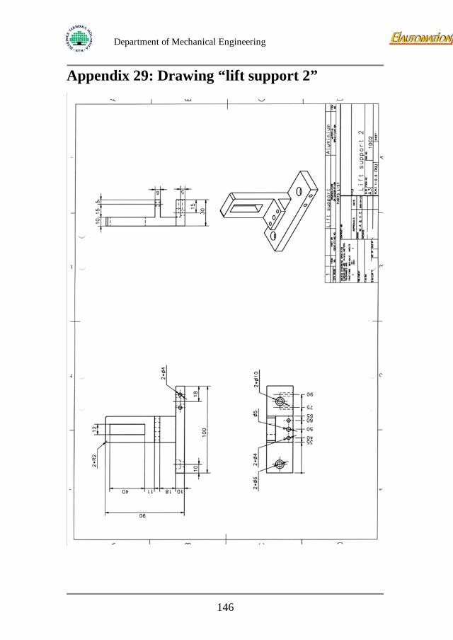
Department of Mechanical Engineering
Appendix 29: Drawing “lift support 2”
146
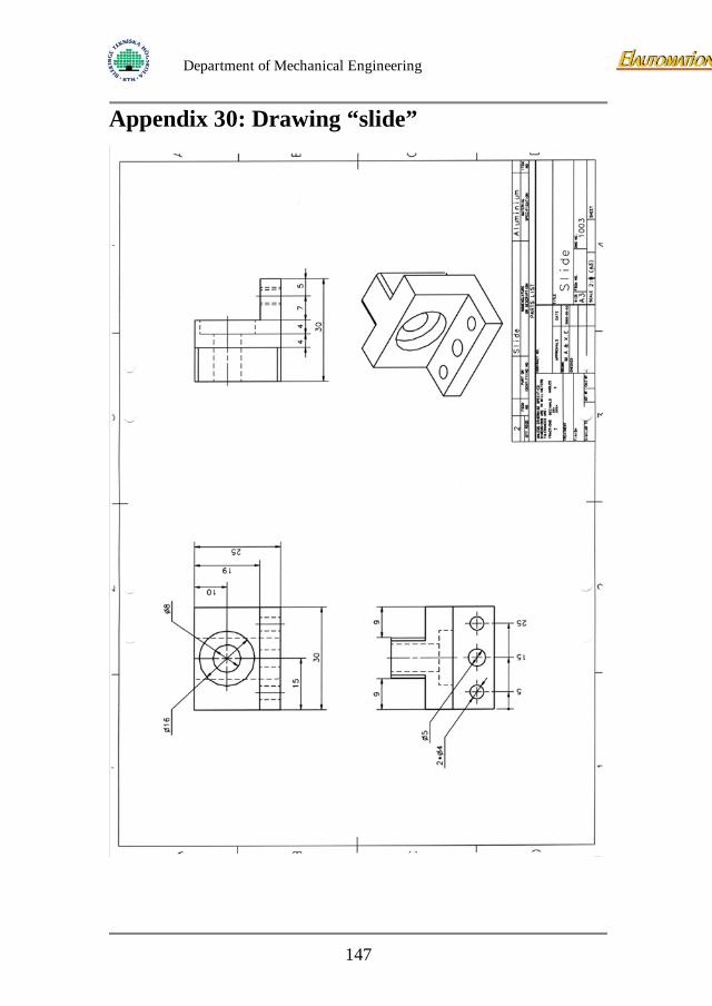
Department of Mechanical Engineering
Appendix 30: Drawing “slide”
147
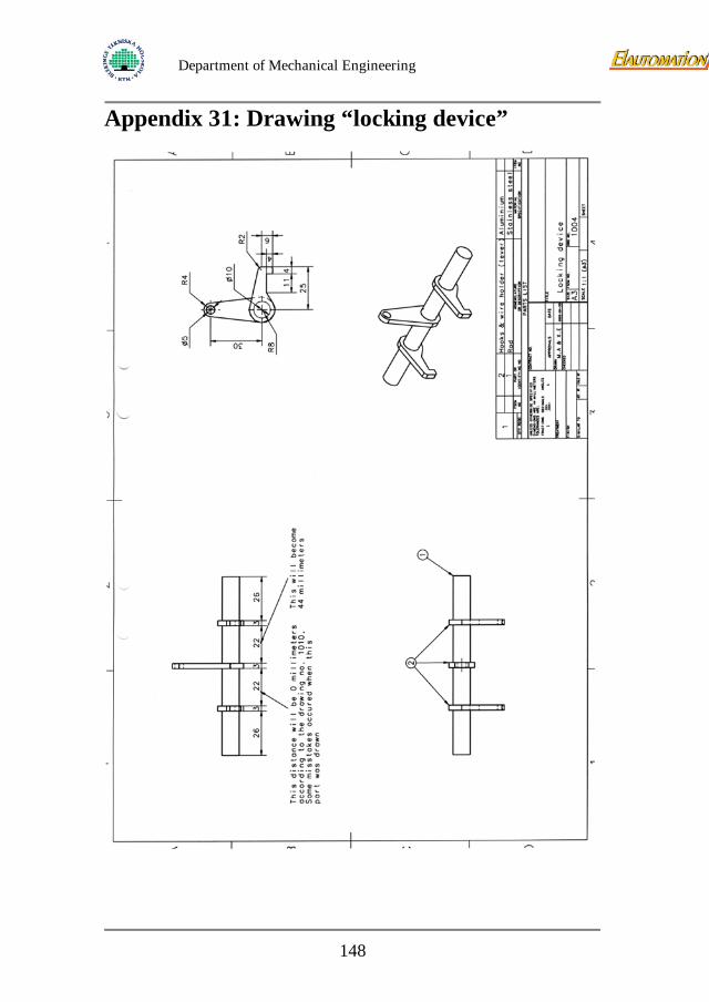
Department of Mechanical Engineering
Appendix 31: Drawing “locking device”
148
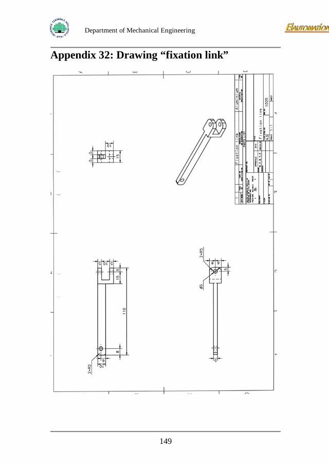
Department of Mechanical Engineering
Appendix 32: Drawing “fixation link”
149

Department of Mechanical Engineering
Appendix 33: Drawing “guidance 1”
150
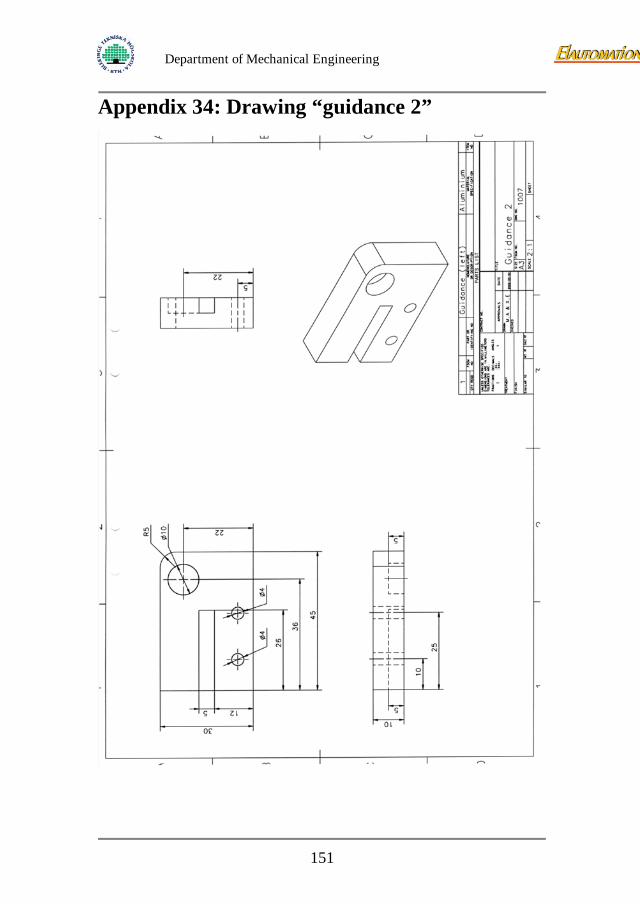
Department of Mechanical Engineering
Appendix 34: Drawing “guidance 2”
151
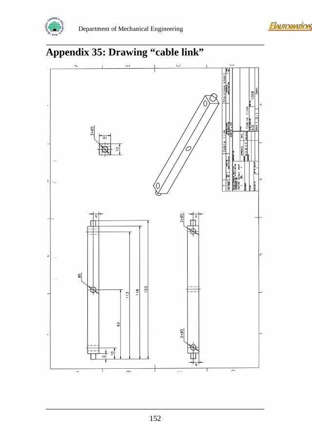
Department of Mechanical Engineering
Appendix 35: Drawing “cable link”
152
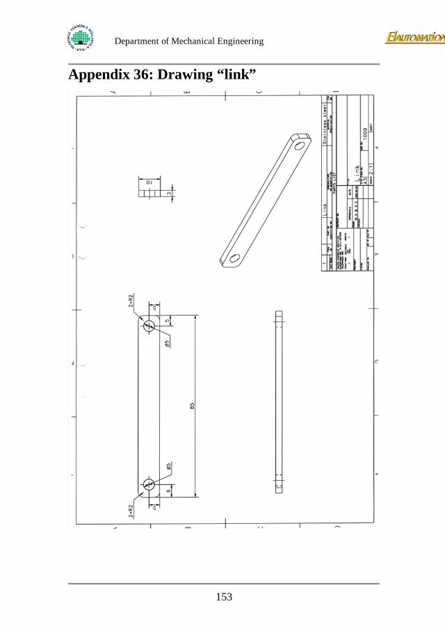
Department of Mechanical Engineering
Appendix 36: Drawing “link”
153
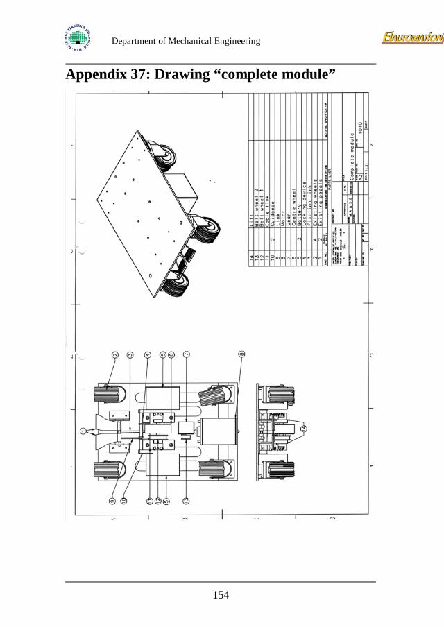
Department of Mechanical Engineering
Appendix 37: Drawing “complete module”
154